EP3586734A1 - Dispositif de mesure de signal biologique - Google Patents
Dispositif de mesure de signal biologique Download PDFInfo
- Publication number
- EP3586734A1 EP3586734A1 EP18757916.4A EP18757916A EP3586734A1 EP 3586734 A1 EP3586734 A1 EP 3586734A1 EP 18757916 A EP18757916 A EP 18757916A EP 3586734 A1 EP3586734 A1 EP 3586734A1
- Authority
- EP
- European Patent Office
- Prior art keywords
- bio
- signal
- power
- electrodes
- circuit
- Prior art date
- Legal status (The legal status is an assumption and is not a legal conclusion. Google has not performed a legal analysis and makes no representation as to the accuracy of the status listed.)
- Granted
Links
- 238000012545 processing Methods 0.000 claims abstract description 89
- 238000005259 measurement Methods 0.000 claims abstract description 30
- 238000000034 method Methods 0.000 claims abstract description 13
- 230000008569 process Effects 0.000 claims abstract description 9
- 239000000758 substrate Substances 0.000 claims description 62
- 230000006854 communication Effects 0.000 claims description 29
- 238000004891 communication Methods 0.000 claims description 29
- 238000012546 transfer Methods 0.000 claims description 28
- 239000002390 adhesive tape Substances 0.000 claims description 19
- 230000006870 function Effects 0.000 claims description 18
- 230000005540 biological transmission Effects 0.000 claims description 14
- 235000014676 Phragmites communis Nutrition 0.000 claims description 13
- 238000001514 detection method Methods 0.000 claims description 11
- 238000005452 bending Methods 0.000 claims description 10
- 230000005389 magnetism Effects 0.000 claims description 8
- 239000004065 semiconductor Substances 0.000 claims description 7
- 239000000463 material Substances 0.000 claims description 6
- 230000003183 myoelectrical effect Effects 0.000 claims description 5
- 239000000696 magnetic material Substances 0.000 claims description 4
- 230000007175 bidirectional communication Effects 0.000 claims description 3
- 230000002159 abnormal effect Effects 0.000 claims description 2
- 238000010586 diagram Methods 0.000 description 22
- XEEYBQQBJWHFJM-UHFFFAOYSA-N Iron Chemical compound [Fe] XEEYBQQBJWHFJM-UHFFFAOYSA-N 0.000 description 4
- 238000012937 correction Methods 0.000 description 4
- 230000001133 acceleration Effects 0.000 description 3
- 239000003990 capacitor Substances 0.000 description 3
- 230000008859 change Effects 0.000 description 3
- 230000009467 reduction Effects 0.000 description 3
- HBBGRARXTFLTSG-UHFFFAOYSA-N Lithium ion Chemical compound [Li+] HBBGRARXTFLTSG-UHFFFAOYSA-N 0.000 description 2
- 238000012217 deletion Methods 0.000 description 2
- 230000037430 deletion Effects 0.000 description 2
- 229910052742 iron Inorganic materials 0.000 description 2
- 229910001416 lithium ion Inorganic materials 0.000 description 2
- 230000001681 protective effect Effects 0.000 description 2
- 208000017657 Menopausal disease Diseases 0.000 description 1
- 208000004056 Orthostatic intolerance Diseases 0.000 description 1
- 230000005856 abnormality Effects 0.000 description 1
- 238000009825 accumulation Methods 0.000 description 1
- 230000006793 arrhythmia Effects 0.000 description 1
- 206010003119 arrhythmia Diseases 0.000 description 1
- 230000002238 attenuated effect Effects 0.000 description 1
- 238000003287 bathing Methods 0.000 description 1
- 230000000903 blocking effect Effects 0.000 description 1
- 230000036772 blood pressure Effects 0.000 description 1
- 210000004556 brain Anatomy 0.000 description 1
- 230000000747 cardiac effect Effects 0.000 description 1
- 238000006243 chemical reaction Methods 0.000 description 1
- 238000012790 confirmation Methods 0.000 description 1
- 230000000694 effects Effects 0.000 description 1
- 230000007613 environmental effect Effects 0.000 description 1
- 230000002349 favourable effect Effects 0.000 description 1
- 230000014509 gene expression Effects 0.000 description 1
- 238000003032 molecular docking Methods 0.000 description 1
- 238000012544 monitoring process Methods 0.000 description 1
- 238000010606 normalization Methods 0.000 description 1
- 239000011505 plaster Substances 0.000 description 1
- 238000007747 plating Methods 0.000 description 1
- -1 preferably Substances 0.000 description 1
- 230000036387 respiratory rate Effects 0.000 description 1
- 230000000630 rising effect Effects 0.000 description 1
- 229920002379 silicone rubber Polymers 0.000 description 1
- 239000004945 silicone rubber Substances 0.000 description 1
Images


Classifications
-
- A—HUMAN NECESSITIES
- A61—MEDICAL OR VETERINARY SCIENCE; HYGIENE
- A61B—DIAGNOSIS; SURGERY; IDENTIFICATION
- A61B5/00—Measuring for diagnostic purposes; Identification of persons
- A61B5/24—Detecting, measuring or recording bioelectric or biomagnetic signals of the body or parts thereof
- A61B5/316—Modalities, i.e. specific diagnostic methods
- A61B5/318—Heart-related electrical modalities, e.g. electrocardiography [ECG]
-
- A—HUMAN NECESSITIES
- A61—MEDICAL OR VETERINARY SCIENCE; HYGIENE
- A61B—DIAGNOSIS; SURGERY; IDENTIFICATION
- A61B5/00—Measuring for diagnostic purposes; Identification of persons
- A61B5/24—Detecting, measuring or recording bioelectric or biomagnetic signals of the body or parts thereof
- A61B5/30—Input circuits therefor
-
- H—ELECTRICITY
- H02—GENERATION; CONVERSION OR DISTRIBUTION OF ELECTRIC POWER
- H02J—CIRCUIT ARRANGEMENTS OR SYSTEMS FOR SUPPLYING OR DISTRIBUTING ELECTRIC POWER; SYSTEMS FOR STORING ELECTRIC ENERGY
- H02J7/00—Circuit arrangements for charging or depolarising batteries or for supplying loads from batteries
- H02J7/0042—Circuit arrangements for charging or depolarising batteries or for supplying loads from batteries characterised by the mechanical construction
-
- A—HUMAN NECESSITIES
- A61—MEDICAL OR VETERINARY SCIENCE; HYGIENE
- A61B—DIAGNOSIS; SURGERY; IDENTIFICATION
- A61B5/00—Measuring for diagnostic purposes; Identification of persons
- A61B5/0002—Remote monitoring of patients using telemetry, e.g. transmission of vital signals via a communication network
-
- A—HUMAN NECESSITIES
- A61—MEDICAL OR VETERINARY SCIENCE; HYGIENE
- A61B—DIAGNOSIS; SURGERY; IDENTIFICATION
- A61B5/00—Measuring for diagnostic purposes; Identification of persons
- A61B5/05—Detecting, measuring or recording for diagnosis by means of electric currents or magnetic fields; Measuring using microwaves or radio waves
- A61B5/053—Measuring electrical impedance or conductance of a portion of the body
- A61B5/0531—Measuring skin impedance
-
- A—HUMAN NECESSITIES
- A61—MEDICAL OR VETERINARY SCIENCE; HYGIENE
- A61B—DIAGNOSIS; SURGERY; IDENTIFICATION
- A61B5/00—Measuring for diagnostic purposes; Identification of persons
- A61B5/24—Detecting, measuring or recording bioelectric or biomagnetic signals of the body or parts thereof
- A61B5/30—Input circuits therefor
- A61B5/304—Switching circuits
-
- A—HUMAN NECESSITIES
- A61—MEDICAL OR VETERINARY SCIENCE; HYGIENE
- A61B—DIAGNOSIS; SURGERY; IDENTIFICATION
- A61B5/00—Measuring for diagnostic purposes; Identification of persons
- A61B5/24—Detecting, measuring or recording bioelectric or biomagnetic signals of the body or parts thereof
- A61B5/316—Modalities, i.e. specific diagnostic methods
- A61B5/318—Heart-related electrical modalities, e.g. electrocardiography [ECG]
- A61B5/346—Analysis of electrocardiograms
- A61B5/349—Detecting specific parameters of the electrocardiograph cycle
- A61B5/352—Detecting R peaks, e.g. for synchronising diagnostic apparatus; Estimating R-R interval
-
- A—HUMAN NECESSITIES
- A61—MEDICAL OR VETERINARY SCIENCE; HYGIENE
- A61B—DIAGNOSIS; SURGERY; IDENTIFICATION
- A61B5/00—Measuring for diagnostic purposes; Identification of persons
- A61B5/24—Detecting, measuring or recording bioelectric or biomagnetic signals of the body or parts thereof
- A61B5/316—Modalities, i.e. specific diagnostic methods
- A61B5/318—Heart-related electrical modalities, e.g. electrocardiography [ECG]
- A61B5/346—Analysis of electrocardiograms
- A61B5/349—Detecting specific parameters of the electrocardiograph cycle
- A61B5/353—Detecting P-waves
-
- A—HUMAN NECESSITIES
- A61—MEDICAL OR VETERINARY SCIENCE; HYGIENE
- A61B—DIAGNOSIS; SURGERY; IDENTIFICATION
- A61B5/00—Measuring for diagnostic purposes; Identification of persons
- A61B5/24—Detecting, measuring or recording bioelectric or biomagnetic signals of the body or parts thereof
- A61B5/316—Modalities, i.e. specific diagnostic methods
- A61B5/318—Heart-related electrical modalities, e.g. electrocardiography [ECG]
- A61B5/346—Analysis of electrocardiograms
- A61B5/349—Detecting specific parameters of the electrocardiograph cycle
- A61B5/355—Detecting T-waves
-
- A—HUMAN NECESSITIES
- A61—MEDICAL OR VETERINARY SCIENCE; HYGIENE
- A61B—DIAGNOSIS; SURGERY; IDENTIFICATION
- A61B5/00—Measuring for diagnostic purposes; Identification of persons
- A61B5/24—Detecting, measuring or recording bioelectric or biomagnetic signals of the body or parts thereof
- A61B5/316—Modalities, i.e. specific diagnostic methods
- A61B5/369—Electroencephalography [EEG]
-
- A—HUMAN NECESSITIES
- A61—MEDICAL OR VETERINARY SCIENCE; HYGIENE
- A61B—DIAGNOSIS; SURGERY; IDENTIFICATION
- A61B5/00—Measuring for diagnostic purposes; Identification of persons
- A61B5/24—Detecting, measuring or recording bioelectric or biomagnetic signals of the body or parts thereof
- A61B5/316—Modalities, i.e. specific diagnostic methods
- A61B5/389—Electromyography [EMG]
-
- A—HUMAN NECESSITIES
- A61—MEDICAL OR VETERINARY SCIENCE; HYGIENE
- A61B—DIAGNOSIS; SURGERY; IDENTIFICATION
- A61B5/00—Measuring for diagnostic purposes; Identification of persons
- A61B5/72—Signal processing specially adapted for physiological signals or for diagnostic purposes
- A61B5/7235—Details of waveform analysis
- A61B5/725—Details of waveform analysis using specific filters therefor, e.g. Kalman or adaptive filters
-
- A—HUMAN NECESSITIES
- A61—MEDICAL OR VETERINARY SCIENCE; HYGIENE
- A61B—DIAGNOSIS; SURGERY; IDENTIFICATION
- A61B5/00—Measuring for diagnostic purposes; Identification of persons
- A61B5/74—Details of notification to user or communication with user or patient ; user input means
- A61B5/746—Alarms related to a physiological condition, e.g. details of setting alarm thresholds or avoiding false alarms
-
- H—ELECTRICITY
- H01—ELECTRIC ELEMENTS
- H01H—ELECTRIC SWITCHES; RELAYS; SELECTORS; EMERGENCY PROTECTIVE DEVICES
- H01H36/00—Switches actuated by change of magnetic field or of electric field, e.g. by change of relative position of magnet and switch, by shielding
- H01H36/0006—Permanent magnet actuating reed switches
-
- H—ELECTRICITY
- H02—GENERATION; CONVERSION OR DISTRIBUTION OF ELECTRIC POWER
- H02J—CIRCUIT ARRANGEMENTS OR SYSTEMS FOR SUPPLYING OR DISTRIBUTING ELECTRIC POWER; SYSTEMS FOR STORING ELECTRIC ENERGY
- H02J7/00—Circuit arrangements for charging or depolarising batteries or for supplying loads from batteries
- H02J7/00032—Circuit arrangements for charging or depolarising batteries or for supplying loads from batteries characterised by data exchange
- H02J7/00034—Charger exchanging data with an electronic device, i.e. telephone, whose internal battery is under charge
-
- H—ELECTRICITY
- H02—GENERATION; CONVERSION OR DISTRIBUTION OF ELECTRIC POWER
- H02J—CIRCUIT ARRANGEMENTS OR SYSTEMS FOR SUPPLYING OR DISTRIBUTING ELECTRIC POWER; SYSTEMS FOR STORING ELECTRIC ENERGY
- H02J7/00—Circuit arrangements for charging or depolarising batteries or for supplying loads from batteries
- H02J7/0029—Circuit arrangements for charging or depolarising batteries or for supplying loads from batteries with safety or protection devices or circuits
- H02J7/0031—Circuit arrangements for charging or depolarising batteries or for supplying loads from batteries with safety or protection devices or circuits using battery or load disconnect circuits
-
- H—ELECTRICITY
- H02—GENERATION; CONVERSION OR DISTRIBUTION OF ELECTRIC POWER
- H02J—CIRCUIT ARRANGEMENTS OR SYSTEMS FOR SUPPLYING OR DISTRIBUTING ELECTRIC POWER; SYSTEMS FOR STORING ELECTRIC ENERGY
- H02J7/00—Circuit arrangements for charging or depolarising batteries or for supplying loads from batteries
- H02J7/0042—Circuit arrangements for charging or depolarising batteries or for supplying loads from batteries characterised by the mechanical construction
- H02J7/0045—Circuit arrangements for charging or depolarising batteries or for supplying loads from batteries characterised by the mechanical construction concerning the insertion or the connection of the batteries
-
- H—ELECTRICITY
- H02—GENERATION; CONVERSION OR DISTRIBUTION OF ELECTRIC POWER
- H02J—CIRCUIT ARRANGEMENTS OR SYSTEMS FOR SUPPLYING OR DISTRIBUTING ELECTRIC POWER; SYSTEMS FOR STORING ELECTRIC ENERGY
- H02J7/00—Circuit arrangements for charging or depolarising batteries or for supplying loads from batteries
- H02J7/0063—Circuit arrangements for charging or depolarising batteries or for supplying loads from batteries with circuits adapted for supplying loads from the battery
-
- H—ELECTRICITY
- H02—GENERATION; CONVERSION OR DISTRIBUTION OF ELECTRIC POWER
- H02J—CIRCUIT ARRANGEMENTS OR SYSTEMS FOR SUPPLYING OR DISTRIBUTING ELECTRIC POWER; SYSTEMS FOR STORING ELECTRIC ENERGY
- H02J7/00—Circuit arrangements for charging or depolarising batteries or for supplying loads from batteries
- H02J7/0068—Battery or charger load switching, e.g. concurrent charging and load supply
-
- A—HUMAN NECESSITIES
- A61—MEDICAL OR VETERINARY SCIENCE; HYGIENE
- A61B—DIAGNOSIS; SURGERY; IDENTIFICATION
- A61B2560/00—Constructional details of operational features of apparatus; Accessories for medical measuring apparatus
- A61B2560/02—Operational features
- A61B2560/0204—Operational features of power management
- A61B2560/0209—Operational features of power management adapted for power saving
-
- A—HUMAN NECESSITIES
- A61—MEDICAL OR VETERINARY SCIENCE; HYGIENE
- A61B—DIAGNOSIS; SURGERY; IDENTIFICATION
- A61B2560/00—Constructional details of operational features of apparatus; Accessories for medical measuring apparatus
- A61B2560/02—Operational features
- A61B2560/0204—Operational features of power management
- A61B2560/0214—Operational features of power management of power generation or supply
-
- A—HUMAN NECESSITIES
- A61—MEDICAL OR VETERINARY SCIENCE; HYGIENE
- A61B—DIAGNOSIS; SURGERY; IDENTIFICATION
- A61B5/00—Measuring for diagnostic purposes; Identification of persons
- A61B5/68—Arrangements of detecting, measuring or recording means, e.g. sensors, in relation to patient
- A61B5/6801—Arrangements of detecting, measuring or recording means, e.g. sensors, in relation to patient specially adapted to be attached to or worn on the body surface
- A61B5/6802—Sensor mounted on worn items
-
- H—ELECTRICITY
- H02—GENERATION; CONVERSION OR DISTRIBUTION OF ELECTRIC POWER
- H02J—CIRCUIT ARRANGEMENTS OR SYSTEMS FOR SUPPLYING OR DISTRIBUTING ELECTRIC POWER; SYSTEMS FOR STORING ELECTRIC ENERGY
- H02J2310/00—The network for supplying or distributing electric power characterised by its spatial reach or by the load
- H02J2310/10—The network having a local or delimited stationary reach
- H02J2310/20—The network being internal to a load
- H02J2310/23—The load being a medical device, a medical implant, or a life supporting device
Definitions
- the present invention relates to a bio-signal measuring device and more specifically, to a bio-signal measuring device which includes a bio-signal measuring instrument (wearable biosensor) which is used in a state of being stuck to a living body (human body), like a sticking plaster, and a power feeder which charges a built-in battery.
- a bio-signal measuring instrument wearable biosensor
- a power feeder which charges a built-in battery.
- a wearable type bio-signal measuring instrument in addition to a bio-signal measuring and processing unit that measures and processes, for example, an electrocardiographic signal, a myoelectric signal, an electroencephalographic signal, or the like, a battery as an internal power source that supplies a power source to the bio-signal measuring and processing unit is built in.
- a secondary battery such as a lithium ion battery is used for the battery, and therefore, an SD terminal or a dedicated charging terminal for charging the secondary battery is provided, and when charging the secondary battery, a power feed terminal of a power feeder is connected to the charging terminal to charge the secondary battery (refer to, for example, PTL 1).
- the entire sensor needs to have a waterproof structure.
- a considerable devisal is required, and a structure becomes complicated, which causes an increase in cost.
- wireless communication means for example, Bluetooth (registered trademark) or the like
- a bio-signal measuring instrument for example, Bluetooth (registered trademark) or the like
- the measured bio-signal is transmitted in real time to external equipment such as a portable terminal.
- external equipment such as a portable terminal.
- the measured bio-signal is stored in a built-in memory, a bio-signal measuring instrument is detached from the human body and connected to a personal computer or a portable terminal to collect the bio-signal from the built-in memory.
- an operating power source (drive power source) is supplied from the secondary battery to the bio-signal measuring and processing unit or the like.
- the operating power source it is preferable to supply the operating power source to the bio-signal measuring and processing unit or the like only when the bio-signal measuring instrument is actually mounted to the human body.
- a first object of the present invention is to enable charging of a secondary battery built in a bio-signal measuring instrument (wearable biosensor) without using a dedicated charging terminal. Further, the object of the present invention is to provide a bio-signal measuring instrument which is compact and thin and can be mounted to a living body almost without discomfort.
- a second object of the present invention is to make it possible to collect a bio-signal through a power feeder which is used in charging, at the time of charging of a secondary battery built in the bio-signal measuring instrument.
- a third object of the present invention is to reduce consumption of a battery built in a bio-signal measuring instrument (wearable biosensor) as much as possible. Further, the present invention has an object to eliminate a mechanical power source switch and enhance waterproofness.
- a bio-signal measuring device including: a bio-signal measuring instrument which is used in a state of being mounted to a living body, in which the bio-signal measuring instrument includes a battery as an internal power source and a charging circuit for the battery, a plurality of electrodes which are brought into contact with a skin surface of a human body at the time of bio-signal measurement and are connected to a predetermined power feeder at the time of charging of the battery, a bio-signal processing circuit which processes bio-signals detected at the electrodes in a predetermined manner, and bio-signal and feed power distribution means, the bio-signal processing circuit and the charging circuit are switchably connected to the electrodes through the bio-signal and feed power distribution means, at the time of the bio-signal measurement, the bio-signals detected at the electrodes are supplied to the bio-signal processing circuit through the bio-signal and feed power distribution means, and at the time of the charging of the
- the bio-signal and feed power distribution means includes a signal transfer circuit and a power transfer circuit
- the signal transfer circuit leads the bio-signal to the bio-signal processing circuit at the time of the bio-signal measurement and blocks a flow of the feed power to the bio-signal processing circuit at the time of the charging of the battery
- the power transfer circuit leads the feed power to the charging circuit at the time of the charging of the battery and blocks a flow of the bio-signal to the charging circuit at the time of the bio-signal measurement.
- the feed power which is supplied from the power feeder is a direct current
- a DC cut filter is used for the signal transfer circuit and a non-linear circuit which includes a diode or a transistor is used for the power transfer circuit.
- a low-pass filter is used for the signal transfer circuit and a high-pass filter and a rectifying circuit are used for the power transfer circuit.
- an on/off switch circuit may be used for the power transfer circuit.
- a reed switch which is controlled by magnetism of magnetism generating means provided on the power feeder side can be used for the switch circuit.
- a semiconductor switch which is turned on and off according to a voltage between the electrodes or impedance between the electrodes may be used for the switch circuit.
- a two-contact switching circuit having a first contact which connects the electrodes to the bio-signal processing circuit and a second contact which connects the electrodes to the charging circuit may be used for the bio-signal and feed power distribution means, and the first contact side may be closed at the time of the bio-signal measurement and the second contact side may be closed at the time of the charging of the battery.
- a reed switch in which the first contact side is closed in a normal state may be used for the two-contact switching circuit, and in this case, at the time of the charging of the battery, the second contact side is closed by magnetism of magnetism generating means provided on the power feeder side.
- the first contact side when a voltage between the electrodes is less than a predetermined voltage value or impedance between the electrodes is equal to or more than a predetermined value, the first contact side may be closed, and when the voltage between the electrodes is equal to or more than the predetermined voltage value or the impedance between the electrodes is less than the predetermined value, the second contact side may be closed.
- the bio-signal measuring device further includes a power feeder having power feed terminals which come into contact with the electrodes at the time of the charging of the battery, in which the power feeder is provided with a charging end determination circuit which terminates the charging of the battery when a current flowing to the power feed terminals is equal to or less than a predetermined value.
- the bio-signal measuring device further includes an automatic power source switch which determines that the electrodes are in contact with the living body, when a resistance value between the electrodes is equal to or less than a predetermined value, and supplies a power source of the battery to the bio-signal processing circuit.
- an aspect in which an electrocardiographic signal measuring and processing unit, an myoelectric signal measuring and processing unit, and an electroencephalographic signal measuring and processing unit are included in the bio-signal processing circuit and the bio-signal measuring device has a mounting state check function of operating predetermined warning means as poor mounting when any of the measured signals shows an abnormal value is also included in the first aspect of the present invention.
- bio-signal processing circuit and the power feeder have a communication function of performing communication through the electrodes and the power feed terminals, and at the time of the charging of the battery, the bio-signal data processed in the bio-signal processing circuit is transmitted to the power feeder side is also included in the first aspect of the present invention.
- a predetermined command can be provided from the power feeder to the bio-signal processing circuit.
- the bio-signal measuring device further includes a first substrate in which the bio-signal processing circuit is mounted on one surface; and a second substrate in which the battery and the charging circuit for the battery are mounted on one surface, in which the electrode is provided on the other surface side of each of the first substrate and the second substrate, and the first substrate and the second substrate are connected through a low-bending rigidity part having conductive wiring.
- each of the first substrate and the second substrate has a waterproof cover which has an opening portion for exposing the electrode and covers a portion other than the electrode.
- the bio-signal measuring device may further include a waterproof cover made of a low-rigidity material, which covers the entirety of the bio-signal measuring instrument including the first substrate, the second substrate, and the low-bending rigidity part, and such an aspect is also included in the first aspect of the present invention.
- the bio-signal measuring device further includes an adhesive tape for mounting which is stuck to the living body prior to the bio-signal measurement, in order to improve the convenience of use, in which connection electrodes to the living body, which are made of a magnetic material, are disposed at an interval equal to an interval between the electrodes on the adhesive tape for mounting, the electrodes are made of a permanent magnet material, and the bio-signal measuring instrument is mounted to the living body through the adhesive tape by magnetic attraction of the electrodes to the connection electrodes.
- a bio-signal measuring device including: a bio-signal measuring instrument which includes a plurality of electrodes which detect a bio-signal in contact with a skin surface of a human body, a bio-signal processing circuit which processes the bio-signals detected at the electrodes in a predetermined manner and stores the processed bio-signals in a memory, a battery as an internal power source, and a charging circuit for the battery, and is used in a state of being mounted to the human body; and a power feeder which supplies predetermined charging power to the battery through the charging circuit, in which the power feeder includes communication means for transmitting the bio-signals stored in the memory to predetermined external equipment.
- the communication means has a bidirectional communication function, and predetermined information which includes a biological data processing program is provided from the external equipment to the bio-signal processing circuit through the communication means.
- the power feeder has power feed terminals which are detachably connected to the electrodes, and communication between the power feeder and the bio-signal measuring instrument is performed through the electrodes and the power feed terminals.
- the bio-signal measuring instrument includes a transmission unit which reads the biological data from the memory and transmits the biological data, and connection detection means for outputting a connection detection signal if the power feed terminals are connected to the electrodes, and the transmission unit transmits the biological data to the power feeder if the connection detection signal is output from the connection detection means.
- the biological data in the memory is deleted after the transmission of the biological data to the power feeder.
- a bio-signal measuring device including: a bio-signal measuring instrument which is used in a state of being mounted to a living body, the bio-signal measuring instrument including a pair of electrodes which is brought into contact with the living body at the time of bio-signal measurement, a bio-signal processing circuit which processes bio-signals detected at the electrodes in a predetermined manner, and a battery which supplies a power source to the bio-signal processing circuit; a power source start switch which turns on and off a power source which is supplied from the battery to the bio-signal processing circuit; and a control unit which controls the power source start switch, in which the control unit monitors an inter-electrode resistance existing between the electrodes, turns off the power source start switch when the inter-electrode resistance is a value exceeding a predetermined threshold value, and supplies a power source from the battery to the bio-signal processing circuit by turning on the power source start switch when the
- the resistors R1 to R4 are high resistance elements having a consumption current of 1 ⁇ A or less.
- the electrode for originally detecting a bio-signal is used as a charging terminal, whereby it is not necessary to provide a dedicated charging terminal such as an SD terminal, and the configuration of the bio-signal measuring instrument is simplified, and thus the size, the weight, and the thickness can be further reduced, and sufficient waterproof measures can be taken.
- the bio-signal measuring device includes the first substrate in which the bio-signal processing circuit is mounted on the surface on one side thereof, and the second substrate in which the battery and the charging circuit for the battery are mounted on the surface on one side thereof, and the electrode is provided on the side of the surface on the other side of each of the first substrate and the second substrate, and the first substrate and the second substrate are connected through the low-bending rigidity part having conductive wiring, is adopted, whereby it is possible to provide a small and thin bio-signal measuring instrument which can be mounted on a living body almost without discomfort.
- the biological data stored in the memory of the bio-signal measuring instrument can be transmitted to the external equipment through the power feeder even during the charging of the battery, and on the contrary, a predetermined command can be provided from the external equipment to the sensor chip through the power feeder or firmware or the like can be rewritten, and therefore, it is possible to collect effective bio-signals in order to analyze data.
- the power source start switch is turned on, so that a power source is supplied from the battery to the bio-signal processing circuit, and otherwise, the power source start switch is turned off. Therefore, battery consumption can be reduced as much as possible.
- the power source switch is composed of a comparator and a resistance element and is not a mechanical power source switch, and therefore, it is possible to enhance waterproofness.
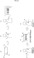
- a bio-signal measuring device includes a bio-signal measuring instrument 1 as a wearable biosensor (sensor chip) and a power feeder (a charger) 2 which feeds charging power to a secondary battery 210 built in the bio-signal measuring instrument 1.
- a bio-signal measuring instrument 1 as a wearable biosensor (sensor chip) and a power feeder (a charger) 2 which feeds charging power to a secondary battery 210 built in the bio-signal measuring instrument 1.
- the bio-signal measuring instrument 1 includes, as a basic configuration, a pair of electrodes 10a and 10b, a bio-signal processing circuit 100, the secondary battery 210 as an internal power source, a charging circuit 200 for charging the secondary battery 210, and bio-signal and feed power distribution means 300.
- the bio-signal processing circuit 100 and the charging circuit 200 are switchably connected to the electrodes 10a and 10b through the bio-signal and feed power distribution means 300.
- the electrodes 10a and 10b are brought into contact with a living body (human body) H at the time of bio-signal measurement and brought into contact with power feed terminals 20a and 20b of the power feeder 2 at the time of charging. That is, in the present invention, the electrodes 10a and 10b are used as both bio-signal detection terminals and charging terminals and do not particularly have terminals for charging only.
- the electrode 10 may include three or more electrodes.
- the bio-signal processing circuit 100 processes a potential or a current such as a cardiac potential, a myoelectric potential, brain waves, or skin resistance as biological data detected at the electrode 10.
- a differential amplifier, an A/D converter, an MCU, a memory, or the like can be used as the bio-signal processing circuit 100.
- a voltage generator or a current generator which causes a current to flow to the living body H through the electrode 10, may be used.
- the charging circuit 200 charges the secondary battery 210 (there is a case where it is simply referred to as a "battery”) such as a lithium ion battery mounted on the bio-signal measuring instrument 1.
- the battery 210 supplies electric power to each part of the bio-signal measuring instrument 1.
- the bio-signal and feed power distribution means 300 leads the bio-signal to the bio-signal processing circuit 100 at the time of the bio-signal measurement and leads the feed power from the power feeder 2 to the charging circuit 200 at the time of the charging.
- the bio-signal and feed power distribution means 300 has several configuration examples.
- a signal transfer circuit 310 and a power transfer circuit 320 are used for the bio-signal and feed power distribution means 300.
- the signal transfer circuit 310 is connected between the electrode 10 and the bio-signal processing circuit 100, and leads the bio-signal to the bio-signal processing circuit 100 at the time of the bio-signal measurement and blocks the flow of the feed power to the bio-signal processing circuit at the time of the charging of the battery.
- the power transfer circuit 320 is connected between the electrode 10 and the charging circuit 200, and leads the feed power to the charging circuit 200 at the time of the charging of the battery and blocks the flow of the bio-signal to the charging circuit 200 at the time of the bio-signal measurement.
- a DC cut filter 311 is used for the signal transfer circuit 310.
- the DC cut filter 311 allows passage of the bio-signal (alternating current) and blocks the passage of DC power.
- the DC cut filter 311 may be a capacitor.
- a non-linear circuit 321 is preferably adopted for the power transfer circuit 320.
- the non-linear circuit 321 has low impedance when power feed voltage is high voltage, and has high impedance at low voltage such as biological voltage, and functions as the power transfer circuit 320.
- non-linear circuit 321 As the non-linear circuit 321, a non-linear circuit 322 having a bridge connection of four diodes D1 to D4 shown in Fig. 4(a) and a capacitor C, and a non-linear circuit 323 having a bridge connection of transistors (in this example, FETs) Tr1 to Tr4 as four semiconductor switches shown in Fig. 4(b) and a capacitor C can be exemplified.
- transistors in this example, FETs
- the non-linear circuits 322 and 323 may be configured of two non-linear elements. However, a full-wave rectifying circuit is formed by forming a bridge with four non-linear elements, whereby, for example, the power feed terminal 20a is set to be a positive pole, the power feed terminal 20b is set to be a negative pole, the positive power feed terminal 20a is connected to the electrode 10a, and the negative power feed terminal 20b is connected to the electrode 10b, and conversely, even if the negative power feed terminal 20b is connected to the electrode 10a and the positive power feed terminal 20a is connected to the electrode 10b, a normal operation is made.
- the transistor Tr can further increase an on-voltage according to a threshold value or reduce a leak current.
- the output voltage of the non-linear circuits 322 and 323 is, for example, in a range of about 4.5 to 6.5 V.
- a low-pass filter 312 is used for the signal transfer circuit 310, and a high-pass filter 324 and a rectifying circuit 325 are used for the power transfer circuit 320.
- the low-pass filter 312 allows passage of the bio-signal. However, it blocks passage of alternating-current feed power.
- the high-pass filter 324 allows the passage of the alternating-current feed power. However, it blocks the passage of the bio-signal.
- the frequency component of the bio-signal is present in a range of around 0.01 Hz to several kHz.
- the frequency which is used for the AC power feed is set to, for example, 13.56 MHz (Industry-Science-Medical band), whereby it can be separated from the bio-signal by about four digits, and thus the low-pass filter 312 can be used effectively.
- the cutoff frequency of the low-pass filter 312 is set to a range of several kHz to several tens of kHz, whereby the feed power can be attenuated by about -40 dB even in a primary filter, and therefore, sufficient blocking performance of the feed power can be obtained.
- the non-linear circuits 322 and 323 shown in Figs. 4(a) and 4(b) may be used for the rectifying circuit 325.
- a switching circuit 326 can also be used for the power transfer circuit 320.
- the switching circuit 326 here is a switching circuit which is turned on and off by switching control means 327, and switches shown in Figs. 7(a) to 7(c) can be exemplified for the switching circuit.
- the switch of Fig. 7(a) is a reed switch 326a.
- a permanent magnet 327a is provided as the switching control means 327 on the power feeder 2 side, and the reed switch 326a is turned on by the permanent magnet 327a at the time of power feeding (charging), and thus the charging power is supplied from the power feeder 2 to the charging circuit 200, and at the time of the bio-signal measurement, the permanent magnet 327a is separated in distance, whereby the reed switch 326a is turned off.
- the switch of Fig 7(b) is composed of a transistor (in this example, FET) 326b as a semiconductor switch, and is turned on and off according to the voltage between the electrodes 10a and 10b.
- An A/D converter (comparator) 327b which detects the voltage between the electrodes 10a and 10b is used for the switching control means 327.
- the power feeder 2 is connected to the electrodes 10a and 10b for charging, and for example, when the voltage between the electrodes 10a and 10b is 5 V or more, the transistor 326b is turned on. It is turned off at the time of living body measurement.
- the switch of Fig. 7(c) is also composed of a transistor (FET) 326c as a semiconductor switch, similar to the switch of Fig. 7(b) . However. In this case, the switch is turned on and off according to the impedance between the electrodes 10a and 10b.
- FET transistor
- a signal generator 327c which supplies a measurement signal having a predetermined frequency between the electrodes 10a and 10b, and an A/D converter (comparator) 327d which detects the impedance between the electrodes 10a and 10b at the time of application of the measurement signal are used for the switching control means 327.
- the transistor 326c is turned on.
- the impedance between the electrodes 10a and 10b has a value of, for example, 10 k ⁇ or more.
- a switching circuit 330 may be used as a fifth example of the bio-signal and feed power distribution means 300.
- the electrode 10 is selectively connected to either the bio-signal processing circuit 100 or the charging circuit 200.
- Three examples thereof are shown in Figs. 9(a) to 9 (c) .
- reed switches 330a and 330b are used.
- Each of the reed switches 330a and 330b is a two-contact switching type which is provided with a first contact a and a second contact b which are selectively connected to a common terminal c through a reed piece.
- the common terminals c of the reed switches 330a and 330b are respectively connected to the electrodes 10a and 10b side, the first contacts a are connected to the bio-signal processing circuit 100, and the second contacts b are connected to the charging circuit 200.
- the permanent magnet 327a which is provided on the power feeder 2 side is used for the switching control means 327.
- both the reed switches 330a and 330b are switched to the second contact b side by the permanent magnet 327a, and thus charging power is supplied from the power feeder 2 to the charging circuit 200.
- the permanent magnet 327a is separated in distance, whereby both the reed switches 330a and 330b are switched to the first contact a side, and thus the electrodes 10a and 10b are connected to the bio-signal processing circuit 100.
- Tr1 to Tr4 are used as semiconductor switches.
- both the sources of the first transistor Tr1 and the second transistor Tr2 are connected to the side of the electrode 10a on one side, and while the drain of the first transistor Tr1 is connected to the bio-signal processing circuit 100, the drain of the second transistor Tr2 is connected to the charging circuit 200.
- both the sources of the third transistor Tr3 and the fourth transistor Tr4 are connected to the side of the electrode 10b on the other side, and while the drain of the third transistor Tr3 is connected to the bio-signal processing circuit 100, the drain of the fourth transistor Tr4 is connected to the charging circuit 200.
- the A/D converter (comparator) 327b which detects the voltage between the electrodes 10a and 10b may be used for the switching control means 327.
- a predetermined control voltage is applied from the A/D converter 327b to the gates of the second transistor Tr2 and the fourth transistor Tr4, whereby the second transistor Tr2 and the fourth transistor Tr4 become conductive (at this time, both the first transistor Tr1 and the third transistor Tr3 are a non-conduction state), and thus the charging circuit 200 is connected to the electrode 10.
- the voltage between the electrodes 10a and 10b is less than 5 V, and therefore, a predetermined control voltage is applied from the A/D converter 327b to the gates of the first transistor Tr1 and the third transistor Tr3, whereby the first transistor Tr1 and the third transistor Tr3 become conductive (at this time, both the second transistor Tr2 and the fourth transistor Tr4 are in a non-conduction state), and thus the bio-signal processing circuit 100 is connected to the electrode 10.
- Fig. 9(c) similar to the example of Fig. 9(b) , four transistors (FETs) Tr1 to Tr4 are used as semiconductor switches. Further, similar to the switching control means previously described in Fig. 7(c) , the signal generator 327c which supplies a measurement signal having a predetermined frequency between the electrodes 10a and 10b, and the A/D converter (comparator) 327d which detects the impedance between the electrodes 10a and 10b are used for the switching control means 327.
- FETs transistors
- Tr1 to Tr4 are used as semiconductor switches.
- the signal generator 327c which supplies a measurement signal having a predetermined frequency between the electrodes 10a and 10b
- the A/D converter (comparator) 327d which detects the impedance between the electrodes 10a and 10b are used for the switching control means 327.
- a predetermined control voltage is applied from the A/D converter 327d to the gates of the second transistor Tr2 and the fourth transistor Tr4, whereby the second transistor Tr2 and the fourth transistor Tr4 become conductive (at this time, both the first transistor Tr1 and the third transistor Tr3 are is a non-conduction state), and thus the charging circuit 200 is connected to the electrode 10.
- the impedance between the electrodes 10a and 10b is, for example, 10 k ⁇ or more, and therefore, a predetermined control voltage is applied from the A/D converter 327d to the gates of the first transistor Tr1 and the third transistor Tr3, whereby the first transistor Tr1 and the third transistor Tr3 become conductive (at this time, both the second transistor Tr2 and the fourth transistor Tr4 are in a non-conduction state), and thus the bio-signal processing circuit 100 is connected to the electrode 10.
- the power feeder 2 includes, in addition to a voltage converter 21, a charging end determination circuit 22, and a overcurrent protection circuit 23, communication means 24, an MPU (microprocessor unit) 25 as a control unit, and a memory 26.
- the voltage converter 21 may be a DC-DC converter or a DC-AC converter, and converts, for example, a DC voltage (5 V) of a USB into a DC or AC voltage.
- a DC voltage 5 V
- AC power feed it outputs a differential voltage of, for example, 13.56 MHz and in a range of about 7 to 10 Vp-p on one side.
- DC power feed it outputs a voltage in a range of 6 to 8 V, for example.
- the charging end determination circuit 22 determines charging end from an attenuation state of the feed power at the power feed terminals 20a and 20b. Even in a case where a determination current is reduced, it is possible to cope with it by performing a charging end determination from a current flowing to the power feed terminals 20a and 20b.
- a charging current before the charging end becomes about 1 mA.
- a current value which is used for the charging end determination is a current value smaller than it, the current value can be detected by using a resistor or a current transformer.
- the overcurrent protection circuit 23 operates, for example, in a case where the power feed terminals 20a and 20b are short-circuited for some reason, and turns off a power feed switch (not shown) in the voltage converter 21.
- the communication means 24 has a function of transmitting biological data or the like stored in the bio-signal measuring instrument 1 to the external equipment (for example, a cloud server or the like), as will be described later, and a function of transferring a command or the like from the external equipment to the bio-signal measuring instrument 1.
- the external equipment for example, a cloud server or the like
- the MPU 25 performs advanced processing that cannot be performed in an MCU 121 (refer to Fig. 14 ) in the bio-signal measuring instrument 1 having a restriction in the power source.
- the MPU 25 performs, for example, encryption processing or anonymization processing in which an individual cannot be identified, from the viewpoint of personal information protection.
- the memory 26 temporarily stores the accumulation of past data, case data on the cloud, or the like.
- the bio-signal measuring instrument 1 includes an automatic power source switch 110 which is provided in the bio-signal processing circuit 100 to detect the living body and automatically turn on (start) the power source.
- the automatic power source switch 110 has a two-input type comparator 111, and the respective one ends of a resistor R1 and a resistor R2 are connected in parallel to an input terminal In1 on one side of the comparator 111.
- the other end of the resistor R1 is connected to an in-device power source V0, and the other end of the resistor R2 is connected to the ground.
- An input terminal In2 on the other side of the comparator 111 is connected to a signal line Lb of the electrode 10b, and a resistor R4 is connected between the input terminal In2 on the other side and the ground.
- a resistor R3 is connected between a signal line La of the electrode 10a and the in-device power source V0.
- V1 and V2 are represented by the following expressions.
- V 1 V 0 ⁇ R 2 / R 1 + R 2
- V 2 V 0 ⁇ R 4 / R 3 + R 4 + R 5 .
- the comparator 111 compares V1 with V2, and when V2 is larger than V1, the comparator 111 instructs a power source start IC 112 to start. For example, if R2, R3, and R4 are set to 10 M ⁇ and R1 is set to 11 M ⁇ , in a case where the resistance value of the resistance R5 is 1 M ⁇ or less, V2 becomes larger than V1, and contact with the living body is regarded as being made, whereby the comparator 111 instructs the power source start IC 112 to start and automatically turns on the power source.
- the automatic power source switch 110 is disconnected from the power source after the start of the power source.
- R1 to R4 are set to have high resistance, as described above, even if the automatic power source switch 110 is not disconnected from the power source after the start of the power source, consumption of consumption power can be minimized.
- R1 to R4 are set to have high resistance, and a consumption current flowing to the comparator 111 and the respective resistors R1 to R4 is always monitored between the electrodes so as to be 1 ⁇ A.
- a half-life period by a current of 1 ⁇ A is about 6 months in a 10 mAh battery, and therefore, there is no influence on the use for several days for collecting biological data.
- the bio-signal measuring instrument 1 has a mounting state check function.
- a skin resistance measuring and processing unit an electrocardiographic signal measuring and processing unit, a myoelectric signal measuring and processing unit, an electroencephalographic signal measuring and processing unit, an environmental physical quantity measuring and processing unit, and the like are provided in the bio-signal processing circuit 100 of the bio-signal measuring instrument 1, and from various data of these units, a mounting state of whether or not the bio-signal measuring instrument 1 is correctly mounted to the living body is checked.
- a determination of whether or not a signal is within the range of a signal level which is expected a determination by a matching comparison (matched filter) with a template of a waveform which is expected, such as an electrocardiographic waveform, a quantitative comparison with a frequency distribution which is expected by performing frequency analysis, or a signal-to-noise ratio (S/N ratio) which is expected, or the like can be used.
- a matching comparison matched filter
- S/N ratio signal-to-noise ratio
- FIGs. 13(a) and 13(b) show a procedure for determining the mounting state by the matching comparison of the electrocardiographic waveform.
- threshold values r1, r2, and r3 are set with respect to a R wave, a P wave, a T wave, a Q wave, and an S wave, and with respect to the R wave, whether or not it is equal to or more than r1 (r1 ⁇ R wave) is determined, and with respect to the P wave and the T wave, whether or not the waves are equal to or more than r2 and less than r1 (r2 ⁇ P wave and T wave ⁇ r1) is determined, and with respect to the Q wave and the S wave, whether or not the waves are less than r3 (Q wave and S wave ⁇ r3) is determined.
- a logic determination on these threshold values in performing a logic determination on these threshold values, an unnecessary signal component is removed from a raw signal by a band pass filter. At that time, a differential signal may be used as necessary.
- the logic determination can be performed by a comparator (either digital or analog).
- the result of the logic determination on the threshold values is shown in (b-2) of Fig. 13(b) .
- normalization may be performed with the maximum peak (in this example, the R wave).
- the logical product is integrated for a certain period, and a threshold value determination of the integral result is performed with a matching determination.
- a threshold value determination of the integral result is performed with a matching determination.
- the bio-signal measuring instrument 1 has a communication function with the power feeder 2.
- the MCU (micro controller unit) 121 In order to perform communication with the power feeder 2, the MCU (micro controller unit) 121, a memory 122, an I/O interface 123, an ADC (analog-digital conversion circuit) 124, and the like are provided in the bio-signal processing circuit 100 of the bio-signal measuring instrument 1.
- the MCU micro controller unit
- a memory 122 In order to perform communication with the power feeder 2, the MCU (micro controller unit) 121, a memory 122, an I/O interface 123, an ADC (analog-digital conversion circuit) 124, and the like are provided in the bio-signal processing circuit 100 of the bio-signal measuring instrument 1.
- ADC analog-digital conversion circuit
- the MCU 121 stores the result of processing the bio-signal in the memory 122 and controls the communication with the power feeder 2. As ab example of the processing of the bio-signal, determining a heart rate fluctuation from the electrocardiographic waveform, or determining a movement distance or the amount of exercise from acceleration can be given.
- the memory 122 includes a RAM (random access memory) and a ROM (read only memory).
- the bio-signal data processed in the MCU 121, or the like is stored in the RAM, and a processing program or the like is written in the ROM.
- the I/O interface 123 generates a signal for sending data to the power feeder 2. Further, the ADC 124 receives data, a measurement program, or the like from the power feeder 2 and performs replacement of firmware, or the like.
- a fifth embodiment of the present invention of the communication function with the power feeder 2 as shown in Fig. 15 , an aspect including a wakeup circuit 131 as connection detection means, a switch (SW) 132 for modulation, an ADC 133, an error correction decoding circuit 134a, an error correction coding circuit 134b, and a communication control unit 135 is also included in the present invention.
- SW switch
- the wakeup circuit 131 detects the feed power (charging power) to determine that this device (the bio-signal measuring instrument 1) is set to the power feeder 2, and causes the communication function to be in an operating state.
- the switch 132 for modulation changes the impedance between the differentials in order to modulate the feed power.
- An external transistor with high withstand voltage can be placed.
- the ADC (a comparator is also acceptable) 133 converts the modulation of the feed power into a binary or multiple values.
- a protective resistor or a protective diode can be placed as necessary.
- the an error correction decoding circuit 134a and the error correction coding circuit 134b reduce the influence of distortion of a transmission path with Reed-Solomon, Viterbi, Turbo, LDPC or the like.
- the communication control unit 135 generates a transmission and reception timing and controls each part.
- Fig. 16 shows an example of data which is transmitted by a communication circuit between the bio-signal measuring instrument 1 and the power feeder 2, and this will be described.
- the heart rate fluctuation is obtained from the electrocardiographic waveform by a Floting Unit of the MCU 121 or dedicated HW (hardware), and the heart rate fluctuation is frequency-decomposed into, for example, 16 gradations through a variable band limiting filter. For this, it is preferable to change and decompose the band of an IIR band limiting filter (BPF) little by little.
- BPF IIR band limiting filter
- Recording is performed every certain time, and for example, recording is performed at a rate of once every 10 seconds.
- the amount of information in 24 hours in a case of frequency-decomposing acceleration is about 10 kB
- the amount of information in 24 hours of a movement distance obtained by integrating acceleration is about 10 kB.
- the power feeder 2 is also referred to as a docking station, and information (biological data or the like) stored in the memory 122 can be transmitted to, for example, a cloud server or the like through the power feeder 2 while charging is performed by connecting the bio-signal measuring instrument 1 to the power feeder 2.
- the sensor chip 1 includes two first and second substrates 30 and 40, and a low-bending rigidity part 50 connecting the substrates 30 and 40.
- a hard substrate such as a copper-clad laminate substrate is used for each of the substrates 30 and 40, and a flexible wiring board is preferably adopted for the low-bending rigidity part 50.
- a flexible wiring board is preferably adopted for the low-bending rigidity part 50.
- the surfaces (front surfaces) on one side of the substrates 30 and 40 shown in Fig. 17(a) are component mounting surfaces 30a and 40a, and in this example, the bio-signal processing circuit 100 is mounted on the component mounting surface 30a of the first substrate 30, the charging circuit 200 is mounted on the component mounting surface 40a of the second substrate 40, and the secondary battery 210 as a power source is mounted on the component mounting surface 40a. Since the secondary battery 210 is heavier than the other components, it is preferable to dispose it on the connection portion side.
- the bio-signal and feed power distribution means 300 may be provided on either the first substrate 30 or the second substrate 40.
- the surfaces on the other side of the substrates 30 and 40 shown in Fig. 17(b) are back surfaces 30b and 40b, and while the electrode 10a on one side is provided on the back surface 30b of the first substrate 30, the electrode 10b on the other side is provided on the back surface 40b of the second substrate 40.
- the electrodes 10a and 10b are connected to the bio-signal processing circuit 100 and the charging circuit 200 through the bio-signal and feed power distribution means 300.
- a length L of the flexible wiring board 50 is preferably as long as possible in order to reduce a force of causing the electrodes 10a and 10b to be peeled off from the skin.
- Each side of the substrates 30 and 40 is set to be 30 mm or less, preferably 20 mm or less.
- the thickness including the electrode 10, the substrates 30 and 40, the bio-signal processing circuit 100, the charging circuit 200, the battery 210, and other members is set to be 10 mm or less, preferably 5 mm or less.
- the substrates 30 and 40 does not need to be necessarily a quadrangle and may have curved portions.
- each of the substrates 30 and 40 is formed of a multilayer build-up substrate which includes an inner layer circuit, and the flexible wiring board 50 is interposed between predetermined inner layers at the time of the build-up.
- the through via 51 may be filled with plating, a resist, or the like.
- disposition may be made such that the bio-signal processing circuit 100 and the battery 210 are disposed on the first substrate 30 on one side and the charging circuit 200 is disposed on the second substrate 40 on the other side.
- the bio-signal processing circuit 100 is disposed on the first substrate 30 on one side and the charging circuit 200 and the battery 210 are disposed on the second substrate 40 on the other side.
- the wiring related to the bio-signal processing is arranged on the first substrate 30 side and the wiring of the power source system is arranged on the second substrate 40. Therefore, a circuit pattern which is formed on the flexible wiring board 50 may have a minimum of power source wiring and control wiring, and the flexible wiring board 50 can be made more flexible.
- the bio-signal processing circuit 100 has a larger circuit area than the charging circuit 200, and therefore, with the disposition shown in Fig. 18(a) , the first substrate 30 and the second substrate 40 can have substantially the same size in area.
- the flexible wiring board 50 is disposed substantially at the central portion in a length direction (a right-left direction in Fig. 18 ) of the sensor chip 1 and the lengths of both the substrates 30 and 40 can be increased. Therefore, the sensor chip 1 can be made difficult to be peeled off from the skin of the living body.
- Fig. 19 shows a waterproof cover 60 of the sensor chip 1.
- Fig. 19(a) is a front view of the waterproof cover 60 which covers the sides of the component mounting surfaces 30a and 40a of the sensor chip 1
- Fig. 19(b) is a rear view of the waterproof cover 60 which covers the sides of the back surfaces 30b and 40b of the sensor chip 1
- Fig. 19(c) is a sectional view taken along ling A-A of Fig. 19(b) .
- the waterproof cover 60 is made of a low-rigidity material, preferably, silicone rubber, and is formed in the form of a bag which accommodates the sensor chip 1 shown in Fig. 17 in the interior thereof. As shown in Fig. 19(b) , opening portions 61a and 61b for exposing the electrodes 10a and 10b are provided on the back surface side.
- the waterproof cover 60 As another example of the waterproof cover 60, as shown in Fig. 20 , a configuration is made in which the waterproof cover 60 is divided into two members; a first waterproof cover 60a covering the first substrate 30 and a second waterproof cover 60b covering the second substrate 40 and the first substrate 30 and the second substrate 40 are individually waterproofed.
- the opening portion 61a for exposing the electrode 10a is provided on the back surface side of the first waterproof cover 60a, and the opening portion 61b for exposing the electrode 10b is provided on the back surface side of the second waterproof cover 60b.
- the portion of the flexible wiring board 50 is not covered with a waterproof cover, and therefore, the inherent flexibility of the flexible wiring board 50 is not lost.
- the sensor chip 1 may be directly mounted to the skin of the living body. However, preferably, an adhesive tape for mounting 70 shown in Figs. 21(a) and 21(b) is used.
- Fig. 21(c) is a schematic diagram showing the electrode surface side of the sensor chip 1
- Fig. 21(d) is a schematic diagram showing the power feed terminal side of the power feeder 2.
- the adhesive tape for mounting 70 has skin-side electrodes 71a and 71b made of biocompatible gel or the like and provided at two right and left locations on the skin sticking surface side (pasting surface side) of Fig. 21(a) . Although not shown, at the time of non-use, the skin-side electrodes 71a and 71b are covered with release paper.
- Connection electrodes 72a and 72b are provided corresponding to the skin-side electrodes 71a and 71b on the surface side (front surface side) shown in Fig. 21(b) of the adhesive tape for mounting 70.
- the connection electrodes 72a and 72b are made of a magnetic material such as iron and are disposed at an interval equal to the interval between the electrodes 10a and 10b of the sensor chip 1.
- the power feed terminals 20a and 20b of the power feeder 2 are also made of a magnetic material such as iron and are disposed at an interval equal to the interval between the electrodes 10a and 10b of the sensor chip 1.
- the electrodes 10a and 10b of the sensor chip 1 are made of a permanent magnet material, and the sensor chip 1 is selectively held on the adhesive tape for mounting 70 and the power feeder 2 by the magnetic attraction forces of the electrodes 10a and 10b.
- Fig. 22 shows a state where the sensor chip 1 is mounted to the adhesive tape for mounting 70.
- the charged sensor chip 1 is mounted to the adhesive tape for mounting 70, as shown in Fig. 22 .
- the sensor chip 1 is held on the adhesive tape for mounting 70 by the electrodes 10a and 10b being magnetically attracted to the connection electrodes 72a and 72b.
- the sensor chips 1 may be mounted to a plurality of places of the living body.
- the sensor chip 1 is detached from the adhesive tape for mounting 70, and (e) the sensor chip 1 is set to the power feeder 2. Also at this time, the electrodes 10a and 10b are magnetically attracted to the power feed terminals 20a and 20b, whereby the sensor chip 1 is reliably held on the power feeder 2.
- the battery 210 of the sensor chip 1 is charged from the power feeder 2.
- the biological data stored in the memory 122 of the bio-signal processing circuit 100 is transferred to the memory 26 of the power feeder 2.
- the transmission of the biological data is performed by the instruction of the MPU 25 of the power feeder 2 and/or the MCU 121 of the sensor chip 1.
- the power feeder 2 has a charge lamp 2a and a communication lamp 2b, the charge lamp 2a is lit during the charging, and the communication lamp 2b is lit during the data transmission.
- the biological data is deleted from the memory 122 of the sensor chip 1. This data deletion is performed by the instruction of either the MCU 121 of the sensor chip 1 or the MPU 25 of the power feeder 2. (f) In this way, the sensor chip 1 from which the biological data has been deleted and which has been charged is used again to acquire the biological data.
- the power feeder 2 is preferably connected to a connection terminal 80 having a connection function to a public line, and transmits the biological data acquired from the sensor chip 1 to a server (cloud server) 81 or the like as the external equipment through, for example, the public line.
- a server cloud server
- the deletion of the biological data from the memory 122 of the sensor chip 1 may be performed after the confirmation of the data transmission to the server 81.
- a personal computer, a portable tablet, a microcomputer-mounted board, or the like may be used as the connection terminal 80.
- a bio-signal measurement program (for example, a program for measurement of a bio-signal related to a menopausal disorders, a orthostatic dysregulation, arrhythmias, or the like, a program for monitoring and storing specific ST waves in detail, or the like) suitable for the user is written to the sensor chip 1 through the power feeder 2 as necessary.
- the communication lamp 2b of the power feeder 2 is lit. However, it does not need to be necessarily performed during the charging. That is, the transmission of the biological data from the sensor chip 1 to the power feeder 2, the transmission of the biological data from the power feeder 2 to the server 81, and program writing from the server 81 to the sensor chip 1 through the power feeder 2 may be performed before or after the charging of the sensor chip 1.
- an electrode for originally detecting a bio-signal is used as a charging terminal, whereby it is not necessary to provide a dedicated charging terminal such as an SD terminal, and the configuration of the bio-signal measuring instrument is simplified, and thus the size, the weight, and the thickness can be further reduced, and sufficient waterproof measures can be taken.
- the power feeder has a communication function (preferably, bidirectional communication) and can transmit the biological data stored in the memory of the bio-signal measuring instrument (sensor chip) to the external equipment through the power feeder even during the charging of the battery, and on the contrary, a predetermined command can be given from the external equipment to the sensor chip through the power feeder or the firmware or the like can be rewritten, and therefore, it is possible to collect effective bio-signals in order to analyze data.
- a communication function preferably, bidirectional communication
- the power source start switch is turned on, so that a power source is supplied from the battery to the bio-signal processing circuit, and otherwise, the power source start switch is turned off. Therefore, battery consumption can be reduced as much as possible.
Landscapes
- Health & Medical Sciences (AREA)
- Life Sciences & Earth Sciences (AREA)
- Engineering & Computer Science (AREA)
- Physics & Mathematics (AREA)
- Biophysics (AREA)
- Veterinary Medicine (AREA)
- Animal Behavior & Ethology (AREA)
- Public Health (AREA)
- General Health & Medical Sciences (AREA)
- Surgery (AREA)
- Molecular Biology (AREA)
- Pathology (AREA)
- Biomedical Technology (AREA)
- Heart & Thoracic Surgery (AREA)
- Medical Informatics (AREA)
- Cardiology (AREA)
- Power Engineering (AREA)
- Psychiatry (AREA)
- Psychology (AREA)
- Physiology (AREA)
- Signal Processing (AREA)
- Computer Vision & Pattern Recognition (AREA)
- Artificial Intelligence (AREA)
- Dermatology (AREA)
- Nuclear Medicine, Radiotherapy & Molecular Imaging (AREA)
- Radiology & Medical Imaging (AREA)
- Computer Networks & Wireless Communication (AREA)
- Measurement And Recording Of Electrical Phenomena And Electrical Characteristics Of The Living Body (AREA)
Applications Claiming Priority (4)
| Application Number | Priority Date | Filing Date | Title |
|---|---|---|---|
| JP2017035208A JP6804334B2 (ja) | 2017-02-27 | 2017-02-27 | 生体信号計測装置 |
| JP2017035211A JP6850156B2 (ja) | 2017-02-27 | 2017-02-27 | 生体信号計測装置 |
| JP2017035212A JP6876464B2 (ja) | 2017-02-27 | 2017-02-27 | 生体信号計測装置 |
| PCT/JP2018/005778 WO2018155386A1 (fr) | 2017-02-27 | 2018-02-19 | Dispositif de mesure de signal biologique |
Publications (3)
| Publication Number | Publication Date |
|---|---|
| EP3586734A1 true EP3586734A1 (fr) | 2020-01-01 |
| EP3586734A4 EP3586734A4 (fr) | 2020-08-12 |
| EP3586734B1 EP3586734B1 (fr) | 2022-08-10 |
Family
ID=63252721
Family Applications (1)
| Application Number | Title | Priority Date | Filing Date |
|---|---|---|---|
| EP18757916.4A Active EP3586734B1 (fr) | 2017-02-27 | 2018-02-19 | Dispositif de mesure de signal biologique |
Country Status (5)
| Country | Link |
|---|---|
| US (1) | US11670949B2 (fr) |
| EP (1) | EP3586734B1 (fr) |
| KR (1) | KR102483256B1 (fr) |
| CN (3) | CN114601472A (fr) |
| WO (1) | WO2018155386A1 (fr) |
Cited By (1)
| Publication number | Priority date | Publication date | Assignee | Title |
|---|---|---|---|---|
| EP3824789A1 (fr) * | 2019-09-04 | 2021-05-26 | Bittium Biosignals Oy | Appareil de mesure de signal biologique, appareil d'accueil et procédés de couplage associés |
Families Citing this family (3)
| Publication number | Priority date | Publication date | Assignee | Title |
|---|---|---|---|---|
| US11844602B2 (en) * | 2018-03-05 | 2023-12-19 | The Medical Research Infrastructure And Health Services Fund Of The Tel Aviv Medical Center | Impedance-enriched electrophysiological measurements |
| KR20210007635A (ko) * | 2019-07-12 | 2021-01-20 | 현대자동차주식회사 | 헬스케어 장치 및 이를 포함하는 차량 시스템 |
| CN112494047B (zh) * | 2020-11-23 | 2022-12-02 | 歌尔科技有限公司 | 一种多功能复用电路及智能穿戴设备 |
Family Cites Families (15)
| Publication number | Priority date | Publication date | Assignee | Title |
|---|---|---|---|---|
| AU2005204433B2 (en) * | 2004-01-16 | 2010-02-18 | Compumedics Medical Innovation Pty Ltd | Method and apparatus for ECG-derived sleep disordered breathing monitoring, detection and classification |
| CN103492222B (zh) * | 2011-04-22 | 2016-01-20 | 三菱电机株式会社 | 充电装置 |
| US20160270717A1 (en) * | 2011-06-10 | 2016-09-22 | Aliphcom | Monitoring and feedback of physiological and physical characteristics using wearable devices |
| TWI486805B (zh) * | 2012-10-09 | 2015-06-01 | Quanta Comp Inc | 健康照護產品與其電源管理方法 |
| WO2014088768A2 (fr) * | 2012-12-04 | 2014-06-12 | Brain Tree Analytics Llc | Électrode multi-usage |
| US9569720B2 (en) * | 2013-03-04 | 2017-02-14 | Hello Inc. | Wearable device with magnets magnetized through their widths or thickness |
| US9161697B2 (en) * | 2013-08-07 | 2015-10-20 | Dynosense, Corp. | System for measuring and recording a user's vital signs |
| JP2016087174A (ja) * | 2014-11-06 | 2016-05-23 | 株式会社東芝 | 電子機器 |
| JP2016126897A (ja) * | 2014-12-26 | 2016-07-11 | 株式会社東芝 | 取付装置および電子機器 |
| US9872619B2 (en) * | 2015-01-05 | 2018-01-23 | Salutron Inc. | Physiological sensor pod with reset circuit |
| JP6210085B2 (ja) | 2015-04-27 | 2017-10-11 | Tdk株式会社 | 生体情報測定装置 |
| JP2018516702A (ja) * | 2015-06-10 | 2018-06-28 | カラ ヘルス, インコーポレイテッドCala Health, Inc. | 取り外し可能な治療装置および監視装置で振戦を治療するための末梢神経刺激用のシステムおよび方法 |
| US9913591B2 (en) * | 2015-07-02 | 2018-03-13 | Verily Life Sciences Llc | Wrist-mounted device with integrated electronics |
| CN205359438U (zh) * | 2015-11-17 | 2016-07-06 | 北京异度矩阵科技有限公司 | 一种磁性吸附式智能体温计及其本体 |
| CN106450863B (zh) * | 2016-09-28 | 2019-05-07 | 佛山市顺德区依士文电子仪器有限公司 | 电极片 |
-
2018
- 2018-02-19 CN CN202210327984.9A patent/CN114601472A/zh active Pending
- 2018-02-19 EP EP18757916.4A patent/EP3586734B1/fr active Active
- 2018-02-19 US US16/486,742 patent/US11670949B2/en active Active
- 2018-02-19 CN CN202210327983.4A patent/CN114601471A/zh active Pending
- 2018-02-19 WO PCT/JP2018/005778 patent/WO2018155386A1/fr active Application Filing
- 2018-02-19 KR KR1020197025074A patent/KR102483256B1/ko active IP Right Grant
- 2018-02-19 CN CN201880014064.3A patent/CN110337267B/zh active Active
Cited By (2)
| Publication number | Priority date | Publication date | Assignee | Title |
|---|---|---|---|---|
| EP3824789A1 (fr) * | 2019-09-04 | 2021-05-26 | Bittium Biosignals Oy | Appareil de mesure de signal biologique, appareil d'accueil et procédés de couplage associés |
| US11241181B2 (en) | 2019-09-04 | 2022-02-08 | Bittium Biosignals Oy | Bio-signal measurement apparatus, docking apparatus and methods of their coupling |
Also Published As
| Publication number | Publication date |
|---|---|
| CN110337267A (zh) | 2019-10-15 |
| US11670949B2 (en) | 2023-06-06 |
| EP3586734A4 (fr) | 2020-08-12 |
| CN114601472A (zh) | 2022-06-10 |
| WO2018155386A1 (fr) | 2018-08-30 |
| CN114601471A (zh) | 2022-06-10 |
| EP3586734B1 (fr) | 2022-08-10 |
| US20190357796A1 (en) | 2019-11-28 |
| KR20190124224A (ko) | 2019-11-04 |
| KR102483256B1 (ko) | 2022-12-30 |
| CN110337267B (zh) | 2022-11-08 |
Similar Documents
| Publication | Publication Date | Title |
|---|---|---|
| EP3586734B1 (fr) | Dispositif de mesure de signal biologique | |
| JP2018139761A (ja) | 生体信号計測装置 | |
| Guerreiro et al. | BITalino-A multimodal platform for physiological computing. | |
| CA2706956C (fr) | Capteur de biopotentiel sans contact | |
| US7643882B2 (en) | Tremor reduction systems suitable for self-application and use in disabled patients | |
| US10973452B2 (en) | Wearable physiological data acquirer and methods of using same | |
| WO2017206461A1 (fr) | Appareil d'électrocardiographie de type à écouteurs | |
| KR102016585B1 (ko) | 생체정보 측정 장치 | |
| CA3084736A1 (fr) | Dispositifs et procede de gestion de bruxisme | |
| CN109498993A (zh) | 一种带有刺激电流调节开关的手持式无线神经刺激器 | |
| EP3429466A1 (fr) | Dispositif mobile de mesure de biosignaux électriques | |
| JP6850156B2 (ja) | 生体信号計測装置 | |
| JP6804334B2 (ja) | 生体信号計測装置 | |
| JP6876464B2 (ja) | 生体信号計測装置 | |
| CN206197966U (zh) | 一种医疗用可录音多功能听诊器 | |
| US20170196511A1 (en) | Electrophysiological testing device | |
| CN113907764A (zh) | 一种穿戴式12导联心电仪的硬件系统 | |
| CN111904409A (zh) | 用于心电监测的柔性传感器及水凝胶柔性心电监测仪 | |
| RU2354978C1 (ru) | Индикатор функционирования автономного электростимулятора желудочно-кишечного тракта | |
| CN209378313U (zh) | 一种带有刺激电流调节开关的手持式无线神经刺激器 | |
| CN213940703U (zh) | 一种咳嗽数据采集装置 | |
| CN209440163U (zh) | 一种智能语音陪诊机器人 | |
| WO2015113322A1 (fr) | Moniteur d'électrocardiogramme à oreillette | |
| RU2102004C1 (ru) | Устройство для съема, регистрации и анализа электрофизиологических сигналов и блок защиты от аварийных токов пациента | |
| Babusiak et al. | Design of one-lead ECG data logger |
Legal Events
| Date | Code | Title | Description |
|---|---|---|---|
| STAA | Information on the status of an ep patent application or granted ep patent |
Free format text: STATUS: THE INTERNATIONAL PUBLICATION HAS BEEN MADE |
|
| PUAI | Public reference made under article 153(3) epc to a published international application that has entered the european phase |
Free format text: ORIGINAL CODE: 0009012 |
|
| STAA | Information on the status of an ep patent application or granted ep patent |
Free format text: STATUS: REQUEST FOR EXAMINATION WAS MADE |
|
| 17P | Request for examination filed |
Effective date: 20190916 |
|
| AK | Designated contracting states |
Kind code of ref document: A1 Designated state(s): AL AT BE BG CH CY CZ DE DK EE ES FI FR GB GR HR HU IE IS IT LI LT LU LV MC MK MT NL NO PL PT RO RS SE SI SK SM TR |
|
| AX | Request for extension of the european patent |
Extension state: BA ME |
|
| DAV | Request for validation of the european patent (deleted) | ||
| DAX | Request for extension of the european patent (deleted) | ||
| A4 | Supplementary search report drawn up and despatched |
Effective date: 20200713 |
|
| RIC1 | Information provided on ipc code assigned before grant |
Ipc: A61B 5/04 20060101AFI20200707BHEP Ipc: A61B 5/0428 20060101ALI20200707BHEP Ipc: A61B 5/0476 20060101ALI20200707BHEP Ipc: H02J 7/00 20060101ALI20200707BHEP |
|
| RIN1 | Information on inventor provided before grant (corrected) |
Inventor name: HIGUCHI, KOHEI Inventor name: MAENAKA, KAZUSUKE Inventor name: TANAKA, AKIO Inventor name: CHAN, CHUNKIT |
|
| REG | Reference to a national code |
Ref country code: DE Ref legal event code: R079 Ref document number: 602018039109 Country of ref document: DE Free format text: PREVIOUS MAIN CLASS: A61B0005040000 Ipc: H02J0007000000 |
|
| GRAP | Despatch of communication of intention to grant a patent |
Free format text: ORIGINAL CODE: EPIDOSNIGR1 |
|
| STAA | Information on the status of an ep patent application or granted ep patent |
Free format text: STATUS: GRANT OF PATENT IS INTENDED |
|
| RIC1 | Information provided on ipc code assigned before grant |
Ipc: H02J 7/00 20060101AFI20220203BHEP |
|
| INTG | Intention to grant announced |
Effective date: 20220222 |
|
| GRAS | Grant fee paid |
Free format text: ORIGINAL CODE: EPIDOSNIGR3 |
|
| GRAA | (expected) grant |
Free format text: ORIGINAL CODE: 0009210 |
|
| STAA | Information on the status of an ep patent application or granted ep patent |
Free format text: STATUS: THE PATENT HAS BEEN GRANTED |
|
| AK | Designated contracting states |
Kind code of ref document: B1 Designated state(s): AL AT BE BG CH CY CZ DE DK EE ES FI FR GB GR HR HU IE IS IT LI LT LU LV MC MK MT NL NO PL PT RO RS SE SI SK SM TR |
|
| REG | Reference to a national code |
Ref country code: AT Ref legal event code: REF Ref document number: 1511276 Country of ref document: AT Kind code of ref document: T Effective date: 20220815 Ref country code: CH Ref legal event code: EP |
|
| REG | Reference to a national code |
Ref country code: IE Ref legal event code: FG4D |
|
| REG | Reference to a national code |
Ref country code: DE Ref legal event code: R096 Ref document number: 602018039109 Country of ref document: DE |
|
| REG | Reference to a national code |
Ref country code: FI Ref legal event code: FGE |
|
| REG | Reference to a national code |
Ref country code: NL Ref legal event code: MP Effective date: 20220810 |
|
| REG | Reference to a national code |
Ref country code: LT Ref legal event code: MG9D |
|
| PG25 | Lapsed in a contracting state [announced via postgrant information from national office to epo] |
Ref country code: SE Free format text: LAPSE BECAUSE OF FAILURE TO SUBMIT A TRANSLATION OF THE DESCRIPTION OR TO PAY THE FEE WITHIN THE PRESCRIBED TIME-LIMIT Effective date: 20220810 Ref country code: RS Free format text: LAPSE BECAUSE OF FAILURE TO SUBMIT A TRANSLATION OF THE DESCRIPTION OR TO PAY THE FEE WITHIN THE PRESCRIBED TIME-LIMIT Effective date: 20220810 Ref country code: PT Free format text: LAPSE BECAUSE OF FAILURE TO SUBMIT A TRANSLATION OF THE DESCRIPTION OR TO PAY THE FEE WITHIN THE PRESCRIBED TIME-LIMIT Effective date: 20221212 Ref country code: NO Free format text: LAPSE BECAUSE OF FAILURE TO SUBMIT A TRANSLATION OF THE DESCRIPTION OR TO PAY THE FEE WITHIN THE PRESCRIBED TIME-LIMIT Effective date: 20221110 Ref country code: NL Free format text: LAPSE BECAUSE OF FAILURE TO SUBMIT A TRANSLATION OF THE DESCRIPTION OR TO PAY THE FEE WITHIN THE PRESCRIBED TIME-LIMIT Effective date: 20220810 Ref country code: LV Free format text: LAPSE BECAUSE OF FAILURE TO SUBMIT A TRANSLATION OF THE DESCRIPTION OR TO PAY THE FEE WITHIN THE PRESCRIBED TIME-LIMIT Effective date: 20220810 Ref country code: LT Free format text: LAPSE BECAUSE OF FAILURE TO SUBMIT A TRANSLATION OF THE DESCRIPTION OR TO PAY THE FEE WITHIN THE PRESCRIBED TIME-LIMIT Effective date: 20220810 |
|
| REG | Reference to a national code |
Ref country code: AT Ref legal event code: MK05 Ref document number: 1511276 Country of ref document: AT Kind code of ref document: T Effective date: 20220810 |
|
| PG25 | Lapsed in a contracting state [announced via postgrant information from national office to epo] |
Ref country code: PL Free format text: LAPSE BECAUSE OF FAILURE TO SUBMIT A TRANSLATION OF THE DESCRIPTION OR TO PAY THE FEE WITHIN THE PRESCRIBED TIME-LIMIT Effective date: 20220810 Ref country code: IS Free format text: LAPSE BECAUSE OF FAILURE TO SUBMIT A TRANSLATION OF THE DESCRIPTION OR TO PAY THE FEE WITHIN THE PRESCRIBED TIME-LIMIT Effective date: 20221210 Ref country code: HR Free format text: LAPSE BECAUSE OF FAILURE TO SUBMIT A TRANSLATION OF THE DESCRIPTION OR TO PAY THE FEE WITHIN THE PRESCRIBED TIME-LIMIT Effective date: 20220810 Ref country code: GR Free format text: LAPSE BECAUSE OF FAILURE TO SUBMIT A TRANSLATION OF THE DESCRIPTION OR TO PAY THE FEE WITHIN THE PRESCRIBED TIME-LIMIT Effective date: 20221111 |
|
| PG25 | Lapsed in a contracting state [announced via postgrant information from national office to epo] |
Ref country code: SM Free format text: LAPSE BECAUSE OF FAILURE TO SUBMIT A TRANSLATION OF THE DESCRIPTION OR TO PAY THE FEE WITHIN THE PRESCRIBED TIME-LIMIT Effective date: 20220810 Ref country code: RO Free format text: LAPSE BECAUSE OF FAILURE TO SUBMIT A TRANSLATION OF THE DESCRIPTION OR TO PAY THE FEE WITHIN THE PRESCRIBED TIME-LIMIT Effective date: 20220810 Ref country code: ES Free format text: LAPSE BECAUSE OF FAILURE TO SUBMIT A TRANSLATION OF THE DESCRIPTION OR TO PAY THE FEE WITHIN THE PRESCRIBED TIME-LIMIT Effective date: 20220810 Ref country code: DK Free format text: LAPSE BECAUSE OF FAILURE TO SUBMIT A TRANSLATION OF THE DESCRIPTION OR TO PAY THE FEE WITHIN THE PRESCRIBED TIME-LIMIT Effective date: 20220810 Ref country code: CZ Free format text: LAPSE BECAUSE OF FAILURE TO SUBMIT A TRANSLATION OF THE DESCRIPTION OR TO PAY THE FEE WITHIN THE PRESCRIBED TIME-LIMIT Effective date: 20220810 Ref country code: AT Free format text: LAPSE BECAUSE OF FAILURE TO SUBMIT A TRANSLATION OF THE DESCRIPTION OR TO PAY THE FEE WITHIN THE PRESCRIBED TIME-LIMIT Effective date: 20220810 |
|
| PGFP | Annual fee paid to national office [announced via postgrant information from national office to epo] |
Ref country code: FR Payment date: 20230221 Year of fee payment: 6 |
|
| REG | Reference to a national code |
Ref country code: DE Ref legal event code: R097 Ref document number: 602018039109 Country of ref document: DE |
|
| PG25 | Lapsed in a contracting state [announced via postgrant information from national office to epo] |
Ref country code: SK Free format text: LAPSE BECAUSE OF FAILURE TO SUBMIT A TRANSLATION OF THE DESCRIPTION OR TO PAY THE FEE WITHIN THE PRESCRIBED TIME-LIMIT Effective date: 20220810 Ref country code: EE Free format text: LAPSE BECAUSE OF FAILURE TO SUBMIT A TRANSLATION OF THE DESCRIPTION OR TO PAY THE FEE WITHIN THE PRESCRIBED TIME-LIMIT Effective date: 20220810 |
|
| PLBE | No opposition filed within time limit |
Free format text: ORIGINAL CODE: 0009261 |
|
| STAA | Information on the status of an ep patent application or granted ep patent |
Free format text: STATUS: NO OPPOSITION FILED WITHIN TIME LIMIT |
|
| PG25 | Lapsed in a contracting state [announced via postgrant information from national office to epo] |
Ref country code: AL Free format text: LAPSE BECAUSE OF FAILURE TO SUBMIT A TRANSLATION OF THE DESCRIPTION OR TO PAY THE FEE WITHIN THE PRESCRIBED TIME-LIMIT Effective date: 20220810 |
|
| 26N | No opposition filed |
Effective date: 20230511 |
|
| PG25 | Lapsed in a contracting state [announced via postgrant information from national office to epo] |
Ref country code: SI Free format text: LAPSE BECAUSE OF FAILURE TO SUBMIT A TRANSLATION OF THE DESCRIPTION OR TO PAY THE FEE WITHIN THE PRESCRIBED TIME-LIMIT Effective date: 20220810 |
|
| REG | Reference to a national code |
Ref country code: DE Ref legal event code: R119 Ref document number: 602018039109 Country of ref document: DE |
|
| PG25 | Lapsed in a contracting state [announced via postgrant information from national office to epo] |
Ref country code: MC Free format text: LAPSE BECAUSE OF FAILURE TO SUBMIT A TRANSLATION OF THE DESCRIPTION OR TO PAY THE FEE WITHIN THE PRESCRIBED TIME-LIMIT Effective date: 20220810 |
|
| REG | Reference to a national code |
Ref country code: BE Ref legal event code: MM Effective date: 20230228 |
|
| GBPC | Gb: european patent ceased through non-payment of renewal fee |
Effective date: 20230219 |
|
| PG25 | Lapsed in a contracting state [announced via postgrant information from national office to epo] |
Ref country code: LU Free format text: LAPSE BECAUSE OF NON-PAYMENT OF DUE FEES Effective date: 20230219 |
|
| REG | Reference to a national code |
Ref country code: IE Ref legal event code: MM4A |
|
| PG25 | Lapsed in a contracting state [announced via postgrant information from national office to epo] |
Ref country code: GB Free format text: LAPSE BECAUSE OF NON-PAYMENT OF DUE FEES Effective date: 20230219 |
|
| PG25 | Lapsed in a contracting state [announced via postgrant information from national office to epo] |
Ref country code: IE Free format text: LAPSE BECAUSE OF NON-PAYMENT OF DUE FEES Effective date: 20230219 Ref country code: GB Free format text: LAPSE BECAUSE OF NON-PAYMENT OF DUE FEES Effective date: 20230219 Ref country code: DE Free format text: LAPSE BECAUSE OF NON-PAYMENT OF DUE FEES Effective date: 20230901 |
|
| PG25 | Lapsed in a contracting state [announced via postgrant information from national office to epo] |
Ref country code: BE Free format text: LAPSE BECAUSE OF NON-PAYMENT OF DUE FEES Effective date: 20230228 |
|
| PGFP | Annual fee paid to national office [announced via postgrant information from national office to epo] |
Ref country code: FI Payment date: 20240228 Year of fee payment: 7 Ref country code: CH Payment date: 20240301 Year of fee payment: 7 |