EP3586592A2 - Prescription cover crop seeding with combine - Google Patents
Prescription cover crop seeding with combine Download PDFInfo
- Publication number
- EP3586592A2 EP3586592A2 EP19180915.1A EP19180915A EP3586592A2 EP 3586592 A2 EP3586592 A2 EP 3586592A2 EP 19180915 A EP19180915 A EP 19180915A EP 3586592 A2 EP3586592 A2 EP 3586592A2
- Authority
- EP
- European Patent Office
- Prior art keywords
- assembly
- cover crop
- underlying surface
- distribution
- distribution assembly
- Prior art date
- Legal status (The legal status is an assumption and is not a legal conclusion. Google has not performed a legal analysis and makes no representation as to the accuracy of the status listed.)
- Granted
Links
- 238000010899 nucleation Methods 0.000 title description 2
- 238000009826 distribution Methods 0.000 claims abstract description 132
- 239000000463 material Substances 0.000 claims abstract description 64
- 238000003306 harvesting Methods 0.000 claims description 107
- 239000003337 fertilizer Substances 0.000 claims description 25
- IJGRMHOSHXDMSA-UHFFFAOYSA-N Atomic nitrogen Chemical compound N#N IJGRMHOSHXDMSA-UHFFFAOYSA-N 0.000 claims description 20
- 229910052757 nitrogen Inorganic materials 0.000 claims description 10
- 230000007423 decrease Effects 0.000 claims description 2
- 235000013339 cereals Nutrition 0.000 description 48
- 230000000007 visual effect Effects 0.000 description 16
- 238000004891 communication Methods 0.000 description 13
- 241000196324 Embryophyta Species 0.000 description 11
- 238000012544 monitoring process Methods 0.000 description 11
- 238000012545 processing Methods 0.000 description 9
- 244000025254 Cannabis sativa Species 0.000 description 8
- 238000000034 method Methods 0.000 description 6
- 239000000618 nitrogen fertilizer Substances 0.000 description 6
- 239000010902 straw Substances 0.000 description 6
- 235000015097 nutrients Nutrition 0.000 description 5
- 240000008042 Zea mays Species 0.000 description 4
- 235000005824 Zea mays ssp. parviglumis Nutrition 0.000 description 4
- 235000002017 Zea mays subsp mays Nutrition 0.000 description 4
- 235000005822 corn Nutrition 0.000 description 4
- 238000000151 deposition Methods 0.000 description 4
- 230000003628 erosive effect Effects 0.000 description 4
- QGZKDVFQNNGYKY-UHFFFAOYSA-N Ammonia Chemical compound N QGZKDVFQNNGYKY-UHFFFAOYSA-N 0.000 description 3
- 238000004140 cleaning Methods 0.000 description 3
- 230000006870 function Effects 0.000 description 3
- 238000013340 harvest operation Methods 0.000 description 3
- 239000004009 herbicide Substances 0.000 description 3
- 229910052751 metal Inorganic materials 0.000 description 3
- 239000002184 metal Substances 0.000 description 3
- 238000002360 preparation method Methods 0.000 description 3
- YZHUMGUJCQRKBT-UHFFFAOYSA-M sodium chlorate Chemical compound [Na+].[O-]Cl(=O)=O YZHUMGUJCQRKBT-UHFFFAOYSA-M 0.000 description 3
- 239000002689 soil Substances 0.000 description 3
- 208000019025 Hypokalemia Diseases 0.000 description 2
- ZLMJMSJWJFRBEC-UHFFFAOYSA-N Potassium Chemical compound [K] ZLMJMSJWJFRBEC-UHFFFAOYSA-N 0.000 description 2
- 230000008859 change Effects 0.000 description 2
- 230000007812 deficiency Effects 0.000 description 2
- 239000000446 fuel Substances 0.000 description 2
- BHEPBYXIRTUNPN-UHFFFAOYSA-N hydridophosphorus(.) (triplet) Chemical compound [PH] BHEPBYXIRTUNPN-UHFFFAOYSA-N 0.000 description 2
- 239000002245 particle Substances 0.000 description 2
- 229910052700 potassium Inorganic materials 0.000 description 2
- 239000011591 potassium Substances 0.000 description 2
- 208000007645 potassium deficiency Diseases 0.000 description 2
- 238000012360 testing method Methods 0.000 description 2
- 230000007704 transition Effects 0.000 description 2
- 241000251169 Alopias vulpinus Species 0.000 description 1
- 235000007319 Avena orientalis Nutrition 0.000 description 1
- 244000075850 Avena orientalis Species 0.000 description 1
- 241000219198 Brassica Species 0.000 description 1
- 235000011331 Brassica Nutrition 0.000 description 1
- 240000008620 Fagopyrum esculentum Species 0.000 description 1
- 235000009419 Fagopyrum esculentum Nutrition 0.000 description 1
- 240000005979 Hordeum vulgare Species 0.000 description 1
- 235000007340 Hordeum vulgare Nutrition 0.000 description 1
- 241000209056 Secale Species 0.000 description 1
- 235000007238 Secale cereale Nutrition 0.000 description 1
- 241000209140 Triticum Species 0.000 description 1
- 235000021307 Triticum Nutrition 0.000 description 1
- 230000006978 adaptation Effects 0.000 description 1
- 230000004075 alteration Effects 0.000 description 1
- 238000013459 approach Methods 0.000 description 1
- 238000011088 calibration curve Methods 0.000 description 1
- 230000001413 cellular effect Effects 0.000 description 1
- 239000000356 contaminant Substances 0.000 description 1
- 239000003989 dielectric material Substances 0.000 description 1
- 238000005516 engineering process Methods 0.000 description 1
- 238000009313 farming Methods 0.000 description 1
- 230000000977 initiatory effect Effects 0.000 description 1
- 230000003993 interaction Effects 0.000 description 1
- 235000021374 legumes Nutrition 0.000 description 1
- 239000007788 liquid Substances 0.000 description 1
- 238000012986 modification Methods 0.000 description 1
- 230000004048 modification Effects 0.000 description 1
- 229910000069 nitrogen hydride Inorganic materials 0.000 description 1
- 230000003287 optical effect Effects 0.000 description 1
- 244000052769 pathogen Species 0.000 description 1
- 230000035515 penetration Effects 0.000 description 1
- 239000010908 plant waste Substances 0.000 description 1
- 230000001737 promoting effect Effects 0.000 description 1
- 238000004162 soil erosion Methods 0.000 description 1
- 238000003860 storage Methods 0.000 description 1
- 239000000126 substance Substances 0.000 description 1
- 238000011144 upstream manufacturing Methods 0.000 description 1
Images


Classifications
-
- A—HUMAN NECESSITIES
- A01—AGRICULTURE; FORESTRY; ANIMAL HUSBANDRY; HUNTING; TRAPPING; FISHING
- A01C—PLANTING; SOWING; FERTILISING
- A01C21/00—Methods of fertilising, sowing or planting
- A01C21/005—Following a specific plan, e.g. pattern
-
- A—HUMAN NECESSITIES
- A01—AGRICULTURE; FORESTRY; ANIMAL HUSBANDRY; HUNTING; TRAPPING; FISHING
- A01D—HARVESTING; MOWING
- A01D43/00—Mowers combined with apparatus performing additional operations while mowing
- A01D43/14—Mowers combined with apparatus performing additional operations while mowing with dispensing apparatus, e.g. for fertilisers, herbicides or preservatives
-
- A—HUMAN NECESSITIES
- A01—AGRICULTURE; FORESTRY; ANIMAL HUSBANDRY; HUNTING; TRAPPING; FISHING
- A01C—PLANTING; SOWING; FERTILISING
- A01C14/00—Methods or apparatus for planting not provided for in other groups of this subclass
-
- A—HUMAN NECESSITIES
- A01—AGRICULTURE; FORESTRY; ANIMAL HUSBANDRY; HUNTING; TRAPPING; FISHING
- A01C—PLANTING; SOWING; FERTILISING
- A01C21/00—Methods of fertilising, sowing or planting
- A01C21/007—Determining fertilization requirements
-
- A—HUMAN NECESSITIES
- A01—AGRICULTURE; FORESTRY; ANIMAL HUSBANDRY; HUNTING; TRAPPING; FISHING
- A01D—HARVESTING; MOWING
- A01D41/00—Combines, i.e. harvesters or mowers combined with threshing devices
- A01D41/12—Details of combines
- A01D41/127—Control or measuring arrangements specially adapted for combines
- A01D41/1271—Control or measuring arrangements specially adapted for combines for measuring crop flow
- A01D41/1272—Control or measuring arrangements specially adapted for combines for measuring crop flow for measuring grain flow
-
- A—HUMAN NECESSITIES
- A01—AGRICULTURE; FORESTRY; ANIMAL HUSBANDRY; HUNTING; TRAPPING; FISHING
- A01D—HARVESTING; MOWING
- A01D41/00—Combines, i.e. harvesters or mowers combined with threshing devices
- A01D41/12—Details of combines
- A01D41/127—Control or measuring arrangements specially adapted for combines
- A01D41/1277—Control or measuring arrangements specially adapted for combines for measuring grain quality
Definitions
- the present disclosure relates to a harvesting machine, and in particular, to a harvesting machine that monitors the harvested crop and distributes a material on the underlying surface during a harvest operation.
- fertilizers are frequently deposited on the underlying surface to supply one or more plant nutrients for subsequently planted or currently growing crops. Fertilizer is often distributed in equal amounts throughout the underlying surface of the field being worked.
- more sophisticated systems may apply fertilizer to the fields utilizing a pre-determined fertilizer prescription. In this example, the underlying surface is analyzed and tested prior to applying the fertilizer to the field and the fertilizer prescription is developed based on the prior field testing. The fertilizer may then be applied to the field in different amounts based on the needs identified by the fertilizer prescription.
- cover crops to manage soil erosion, reduce weed growth, and increase soil quality for the primary crop.
- Many different types of cover crops are utilized on a field based on the needs of the farmer.
- the cover crops are typically distributed consistently throughout the field and allowed to grow after a harvest operation has been performed to harvest the primary crop.
- Developing a prescription for applying a surface preparation to a field often requires data obtained from prior harvesting operations or from prior field testing.
- the field must be traversed multiple times by a tractor or other work machine to obtain data to develop a prescription. Then, the tractor or other work machine applies the material to the underlying surface that corresponds with the prescription.
- This approach costs the user time and fuel to generate a prescription and apply the prescription by depositing the corresponding material on the underlying surface.
- One embodiment of the present disclosure is a work machine with a sensing assembly that identifies characteristics of an underlying surface and a distribution assembly that distributes material to the underlying surface.
- the sensing assembly identifies the characteristics of the underlying surface and the distribution assembly distributes varying amounts of material based on the characteristics as the work machine moves along the underlying surface.
- One example of this embodiment includes a harvesting assembly that executes a harvesting operation, wherein the harvesting operation is executed at substantially the same time as the distribution assembly distributes material on the underlying surface.
- the sensing assembly identifies the characteristics at substantially the same time as the harvesting operation.
- the sensing assembly includes a mass flow sensor that identifies a current yield amount during the harvesting operation, wherein the distribution assembly distributes material at a distribution rate based on the current yield amount.
- the distribution rate is a first rate and when the current yield is a second value, the distribution rate is a second rate, the first rate being different from the second rate.
- the distribution assembly is a planter and the material is a cover crop seed, wherein the distribution assembly varies the density of cover crop seed distributed on the underlying surface based on the characteristics identified by the sensing assembly.
- the distribution assembly comprises a plurality of cover crop varieties and the material distributed by the distribution assembly is at least one of the cover crop varieties.
- the characteristics of the underlying surface are saved in a memory unit.
- the characteristics of the underlying surface may be any of a crop yield, grain moisture, grade, or nitrogen level.
- Another embodiment of this disclosure is a system for planting a cover crop during a harvesting operation.
- the system has a harvesting assembly that harvests crops from an underlying surface, a sensing assembly that monitors harvested crop, and a cover crop distribution assembly that selectively distributes cover crop seed on the underlying surface.
- the cover crop distribution assembly modifies cover crop seed distribution during the harvesting operation based on feedback from the sensing assembly.
- the sensing assembly comprises a mass flow sensor that identifies a current yield value during the harvesting operation.
- the cover crop distribution assembly increases the cover crop seed applied to the underlying surface.
- the cover crop distribution assembly comprises a first cover crop seed variety and a second cover crop seed variety, wherein the cover crop distribution assembly selects which of the first cover crop seed variety or the second cover crop seed variety to apply to the underlying surface based on the feedback from the sensing assembly.
- the cover crop distribution assembly has more than one variety of cover crop and the distribution assembly selects one of the cover crop varieties to apply to the underlying surface based on inputs from the sensing assembly.
- the cover crop distribution assembly records cover crop distribution data during the harvesting operation, wherein the cover crop distribution data identifies the amount of cover crop seed distributed on the underlying surface during the harvesting operation.
- the cover crop distribution data includes a geographic location indicator.
- the cover crop distribution data is a cover crop prescription.
- Yet another embodiment of the present disclosure is a method for actively managing and distributing a cover crop during a harvesting operation of a work machine.
- the method includes providing a harvesting assembly, a sensing assembly, a cover crop distribution assembly, and a controller; harvesting crop with the harvesting assembly as the work machine travels along an underlying surface; monitoring the harvested crop, with the controller communicating with the sensing assembly, to determine crop characteristics; and manipulating the cover crop distribution assembly, with the controller, to distribute cover crop seed on the underlying surface at a density that corresponds with the determined crop characteristics.
- the controller determines the crop characteristics throughout the harvesting operation and actively adjusts the density responsive to a change in crop characteristics.
- the crop characteristics monitored by the controller through the sensing assembly are any of a yield or a grain quality.
- the crop distribution assembly has a plurality of cover crop varieties, wherein the controller selects an ideal cover crop variety from the plurality of cover crop varieties based on the crop characteristics before the manipulating the cover crop distribution assembly step.
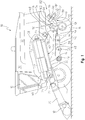
- FIG. 1 an embodiment of an agricultural combine 10 is shown with a chassis 12 with wheels 14 in contact with the underlying surface. Wheels 14 are coupled to the chassis 12 and are used for a forward propulsion of the combine 10 in a forward operating or travelling direction. The forward operating direction is to the left in Fig. 1 .
- the operation of the combine 10 is controlled from an operator's cab 16.
- the operator's cab 16 may include any number of controls (not shown) for controlling the operation of the combine 10.
- a cutter head 18 is disposed at a forward end of the combine 10 and is used in order to harvest crop such as corn and to conduct it to a slope conveyor 20.
- the guide drum 22 guides the harvested crop through an inlet transition section 24 to an axial harvested crop processing arrangement 26, as shown in Fig. 1 .
- the harvested crop processing arrangement 26 may include a rotor housing 34 and a rotor 36 arranged therein.
- the rotor 36 includes a hollow drum 38 to which crop processing elements are fastened for a charging section 40, a threshing section 42, and a separating section 44.
- the charging section 40 is arranged at the front end of the axial harvested crop processing arrangement 26.
- the threshing section 42 and the separating section 44 are located downstream in the longitudinal direction and to the rear of the charging section 40.
- the drum 38 may be in the form of a truncated cone located in the charging section 40.
- the threshing section 42 may include a forward section in the form of a truncated cone and a cylindrical rear section.
- the cylindrical separating section 44 of the drum 38 is located at the rear or end of the axial harvested crop processing arrangement 26.
- a tangential threshing drum with a following axial threshing section or a straw chopper could also be used.
- Corn and chaff that fall through a thresher basket associated with the threshing section 42 and through a separating grate associated with the separating section 44 may be directed to a cleaning system 28 with a blower 46 and sieves 48, 50 with louvers.
- the sieves 48, 50 can be oscillated in a fore-and-aft direction.
- the cleaning system 28 removes the chaff and guides the clean corn or other clean crop over a screw conveyor 52 to a paddle elevator for clean corn or clean crop.
- the elevator for clean crop deposits the clean crop in a clean crop tank 30, as shown in Fig. 1 .
- the clean crop in the crop tank 30 can be unloaded by means of an unloading screw conveyor 32 to a crop wagon, trailer, or truck.
- Harvested crop remaining at the lower end of the lower sieve 50 is again transported to the harvested crop processing arrangement 26 by a screw conveyor 54 and an overhead conveyor.
- the harvested crop residue delivered at the upper end of the upper sieve 48 that consist essentially of chaff and small straw particles or other debris may be conveyed by means of an oscillating sheet conveyor 56 to the rear and to a lower inlet 58 of a chopper rotor assembly 60.
- the aforementioned blower 46 produces an air flow that carries much of the chaff and other debris to the rear of the combine and to the chopper rotor assembly 60.
- the blower 46 is capable of providing three or more air paths inside the combine.
- a first air or flow path may be through a front portion of the combine 10.
- a second air or flow path may be above the lower sieve 50 and below the upper sieve 48 or chaffer.
- a third air or flow path may be below the lower sieve 50. All three air or flow paths fill the combine body and can create pressurized air flow to pick up and carry straw, grain, and other residue or particles to the rear of the combine 10.
- Threshed-out straw leaving the separating section 44 is ejected through an outlet 62 from the harvested crop processing arrangement 26 and conducted to an ejection drum 64.
- the ejection drum 64 or discharge beater, interacts with a sheet 66 arranged underneath it to eject the straw to the rear, and the grain and MOG is directed through the cleaning system 28.
- a wall 68 is located to the rear of the ejection drum 64. The wall 68 guides the straw into an upper inlet 70 of the chopper rotor assembly 60.
- the chopper rotor assembly 60 may include a housing 72 (i.e., chopper housing) with a rotor 74 arranged therein that can rotate in a counterclockwise direction about an axis extending horizontally and transverse to the direction of operation.
- the rotor 74 may include a plurality of chopper knives 76, pendulously suspended in pairs and distributed around the circumference of the rotor 74, that interact with opposing knives 78, which are fixed to the housing 72.
- Two impeller blowers 82 arranged side by side alongside each other, may be provided downstream of an outlet 80 of the chopper rotor assembly 60. Only a single blower 82 is shown in Fig. 1 .
- the impeller blowers 82 may include a number of impeller blades 84, each of which is connected rigidly to an upper circular disk 86, that can rotate about central axes 88.
- the disks 86 with the impeller blades 84 that extend radially can be rotatably driven by a hydraulic motor 90 that is attached above a bottom sheet 102 which is connected with the housing 72 of the chopper rotor assembly 60.
- the impeller blades 84 are connected to a cylindrical central body 92 that transitions into a cone 94 with a point on its end facing away from the disk 86.
- the impeller blades 84 may be rectangular and the height of the body 92 (without cone 94) may be equal to the height of the impeller blades 84.
- the cross section of the body 92 and the cone 94 may be circular, although it could also have a multifaceted shape.
- a mass flow sensor may be positioned in the combine 10 to facilitate identification of the yield of the combine 10 during a harvesting operation.
- the mass flow sensor comprises an impact plate having an arm which is axially aligned with the predominant grain flow from the paddle elevator.
- the arm is coupled to a force measuring assembly having a potentiometer or the like for generating an electric signal that is proportional to impact force.
- the controller may utilize the impact force to determine the current yield being produced during the harvesting operation.
- the combine 10 may have a moisture sensor mounted to the elevator.
- the moisture sensor may have a chamber having an inlet for receiving clean grain from the paddle elevator and an outlet for inserting grain back through the outlet formed in the wall of the paddle elevator.
- the chamber may have a grain moisture analyzer having means for bypassing a portion of the clean grain in the elevator through the chamber.
- a flow control means or feed means comprising a paddle wheel is located just upstream from the outlet.
- the paddle wheel has four flexible rubber paddles that extend across the chamber between the sidewalls for controlling the flow of grain out of the chamber.
- the paddle wheel is rotated by an electric motor that is provided with suitable gearing for slowing its output.
- the paddle wheel controls the flow of grain through the chamber so that there is an adequate sample of grain to sense grain moisture.
- the chamber of the moisture sensor is also provided with a capacitance sensing means such as a sensing cell that has a first, second, and third metal plates.
- the first two metal plates are adjacent and parallel to the walls of the chamber.
- the first and second plates are electrically coupled to one another by jumpers.
- the first and second plates, and the jumpers may be formed from a single piece of sheet metal that is bent in a U-shape.
- the third plate is parallel to the first two plates and positioned between them. All the plates are coupled to an electrical controller. Clean grain flowing between the plates forms a dielectric material which varies the capacitance of the system as moisture content varies in the grain.
- the electronic controller monitors the change in capacitance and relates this to grain moisture by utilizing various capacitance/grain moisture calibration curves that can be derived experimentally for various grains.
- the grain quality being produced during a harvesting operation may be monitored utilizing some or all of the techniques described in U.S. Patent No. 9,779,330 issued to Deere and Company, the detailed description of which is incorporated herein by reference.
- the combine 10 may implement a grain quality visual monitoring system.
- the visual monitoring system may estimate or determine the quality of bulk grain being processed by the combine 10.
- the visual monitoring system may have a bulk grain image source, such as a camera, coupled to a controller and a display among other things.
- the bulk grain image source may have one or more devices configured to capture at least one image of bulk grain for analysis by the visual system in determining quality of the grain.
- “bulk grain” refers to a mass of harvested product which when clean includes only grain of the particular intended crop being harvested (or “clean crop"), but which, when not clean, additionally includes some of broken grain, skinned grain, unthreshed grain of the intended crop, grain of unintended plants such as weeds or volunteer plants, and/or other non-grain elements such as chaff, hulls, sticks, stock, cobs, stems, pods, dirt or other foreign contaminants and debris.
- a camera such as an optical camera or an infrared camera, captures at least one image of bulk grain. The camera may be mounted on any portion of the combine 10 that allows the camera to take a picture of the bulk grain. Further, multiple cameras may be implemented to monitor the grain quality in different portions of the combine 10.
- the visual monitoring system may implement the camera or cameras to analyze the quality of the bulk grain being processed.
- the visual monitoring system may include a quality determination analysis that identifies the quality of the bulk grain visualized by the camera or cameras.
- the quality determination analysis may identify the percentage of clean crop, broken grain, and MOG present in the bulk grain to name a few.
- the visual monitoring system may be utilized to monitor any characteristic of the bulk grain that can be assessed by the cameras and this disclosure considers monitoring other characteristics of the bulk grain as well.
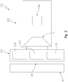
- FIG. 2 illustrates a schematic representation 200 of a harvesting assembly 202 with a distribution assembly 204 coupled thereto.
- the harvesting assembly 202 may be substantially the same as the combine 10 described above with reference to Fig. 1 . However, the harvesting assembly 202 may differ from the combine 10 because it has a distribution assembly 204 coupled thereto.
- the harvesting assembly 202 may contain all of the components of the combine 10 and be capable of performing all of the functions described above for the combine 10.
- the harvesting assembly 202 may also have a sensing assembly 206.
- the sensing assembly 206 may utilize any of the sensors described above to monitor harvested crop. More specifically, the sensing assembly 206 may have any one or more of a mass flow sensor, a moister sensor, a grain quality sensor, or the like on the harvesting assembly 202 to monitor the crop being harvested.
- the sensing assembly 206 may include any type of sensor known in the art to identify the quality of the harvested crop or the underlying surface.
- the harvesting assembly 202 may be capable of performing a harvesting operation.
- the cutter head 18 may sever underlying crop and direct the severed crop through the slope conveyer 20 as described above for the combine 10.
- the harvesting assembly 202 may implement the components described above for the combine 10 to clean and separate the harvested crop into clean crop (typically a grain) and crop debris (such as chaff).
- the clean crop is typically stored in the clean crop tank 30 until it is removed from the harvesting assembly 202 onto a separate transport vehicle.
- the chaff is typically discharged from the combine 10, or the harvesting assembly 202, via the outlet 80.
- the harvesting assembly 202 may also have the distribution assembly 204 coupled thereto.
- the distribution assembly 204 is illustrated coupled to the harvesting assembly 202 between the cutter head 18 and the operator's cab 16.
- the distribution assembly 204 may be coupled to the harvesting assembly 202 underneath the slope conveyer 20.
- this disclosure contemplates mounting the distribution assembly anywhere on the harvesting assembly 202, and the particular locations discussed herein are not exhaustive. More specifically, in another embodiment of this disclosure the distribution assembly 204 may be coupled to the harvesting assembly 202 on a back side that is the opposite side of the harvesting assembly 202 from the cutter head 18. Further still, in other embodiments the distribution assembly 204 may be towed behind the harvesting assembly 204 via a drawbar or other hitched engagement to the harvesting assembly 202.
- the distribution assembly 204 may be a fertilizing assembly, a planting assembly, or any other assembly that deposits a material on the underlying surface. More specifically, if the distribution assembly 204 is a fertilizing assembly it may be configured as a liquid or dry product application. In some non-exclusive examples, the fertilizing assembly may be an anhydrous ammonia (NH3) applicator, a sprayer, a dry box spreader, or a strip till applicator. Further, the distribution assembly 204 may implement a rate controller to vary the distribution rate of the fertilizer being distributed therefrom.
- NH3 anhydrous ammonia
- the distribution assembly 204 may implement a rate controller to vary the distribution rate of the fertilizer being distributed therefrom.
- a rate controller 2000 is a product made by Deere & Company called the "Rate Controller 2000", however, this disclosure may be implemented using any controller capable of altering fertilizer distribution rates.
- the distribution assembly 204 may be a planting assembly that can selectively plant or otherwise distribute a seed on or in the underlying surface.
- the planting assembly may be configured to distribute a cover crop on the underlying surface.
- the seed density, or the rate in which the seed is distributed on the underlying surface may be altered by a controller.
- the distribution assembly 204 may implement, in part, the teachings of U.S. Patent No. 8,948,980 assigned to Deere & Company, the detailed description of which being incorporated herein by reference.
- the distribution assembly 204 may be a seeding machine, such as a row crop planter, which is adapted to switch between two or more seed varieties as the machine traverses a field.
- the distribution assembly 204 may be capable of distributing at least a first variety 208 and a second variety 210 therefrom.
- the varieties 208, 210 may contain material such as different types of cover crop seed.
- other embodiments may include material in the different varieties 208, 210 such as different types of fertilizers or ground coverings as well.
- distribution assembly 204 or harvesting assembly 202 may utilize a controller for controlling the function of the distribution assembly 204 as described in the '980 patent.
- the controller may control the operation of actuators that rotate gates to determine which seed variety flows into a meter housing.
- the controller may also control the rotation speed of seed disks to determine and vary the seed application rate, that is, the number of seeds per unit of area, e.g. seeds per acre.
- the distribution assembly 204 may be any type of variable rate or variety applicator known in the art.
- the distribution assembly 204 may be capable of distributing different types and quantities of material on or in the underlying surface.
- the materials being applied by the distribution assembly 204 contemplated herein may be any of seed, fertilizer, or any other material applied to a field.
- the control system 300 of Fig. 3 illustrates a controller 302 in communication with the sensing assembly 206 and the distribution assembly 204.
- the controller 302 may have a memory unit and may take any form known in the art at the time of this disclosure, and is not limited to any particular form or location. Rather, the controller 302 can be anything capable of storing and processing data and executing commands. While controller 302 is used herein in a singular form, multiple controllers are also considered for executing the logic described. More specifically, in one non-exclusive example the controller 302 may include a combine controller 304, a distribution assembly controller 306, and a remote controller 308 to name a few non-exclusive examples.
- the control system 300 may also have a user interface 322 and a Global Positioning System (GPS) 324 in communication with the controller 302.
- the user interface 322 may be a touch screen, buttons, microphone, camera, or any other sensor capable of receiving a command from a user.
- the user interface provides a way for the user to input parameters for the control system 300.
- the GPS 324 may provide geographical data to the controller 302 that can be stored and monitored therein.
- the controller 302 may store data obtained from the sensing assembly 206 along with a corresponding GPS reading from the GPS 324.
- the controller 302 may save data in a memory unit or the like regarding field characteristics along with the specific geographic location of the data region obtained from the GPS 324.
- the combine controller 304 may be any controllers that control systems of the harvesting assembly 202.
- the combine controller 304 may be a controller on the harvesting assembly 202 in communication with the sensing assembly 206.
- other controllers are considered herein as well and any controller of the harvesting assembly 202 could implement the teachings of this disclosure.
- the distribution assembly controller 306 may be a controller that is particularly designed to control the distribution assembly 204. If the distribution assembly controller 306 is a controller dedicated to the distribution assembly 204, it may communicate with any other systems of the controller 302 to execute the logic described herein.
- the controller 302 may also be wholly or partially located remotely from the harvesting assembly 202. More specifically, the remote controller 308 may not be a controller that is physically located on the harvesting assembly 202 but rather a controller located remotely therefrom. In this embodiment, the remote controller 308 may be located on a wireless device that communicates with the harvesting assembly 202 to execute the logic described herein.
- the remote controller 308 may utilize any known wireless signal to communicate with the harvesting assembly 202. More specifically, the remote controller 308 may utilize cellular signals, radio signals, satellite communications, Bluetooth, or any other known wireless protocol to control components of the harvesting assembly 202 as described herein.
- the controller 302 may be in communication with the sensing assembly 206 and the distribution assembly 204 via one or more communication protocol 310.
- the communication protocol 310 may be wired or wireless communication between the controller 302 and the sensing assembly 206 and the distribution assembly 204.
- the communication protocol 310 may be electrical signals sent via a wire harness to the controller 302 such as a CAN bus.
- the communication protocol 310 may utilize known wireless technology to wirelessly communicate between the controller 302 and the distribution assembly 204 and the sensing assembly 206. Accordingly, this disclosure considers any known form of communication between the sensing assembly 206 and the controller 302 and the distribution assembly 204 and the controller 302.
- the sensing assembly 206 may include one or more of the sensors described above for the harvesting assembly 202. More specifically, the sensing assembly 206 may include a mass flow sensor 312 that communicates with the controller 302 to identify the current yield of the harvesting assembly 202. Similarly, the sensing assembly 206 may be in communication with a moisture sensor 314 as described above. The controller 302 may utilize the communications with one or more of the mass flow sensor 312 and the moisture sensor 314 to identify the current yield of the harvesting assembly 202 during the harvesting operation as is known in the art.
- the controller 302 may also communicate with a visual monitor 316 to identify characteristics of the harvested crop as described above for the visual monitoring system.
- the visual monitors 316 may communicated with the controller to identify the quality of the harvested crop. For example, the visual monitor 316 may identify the amount of MOG in the harvested crop or the amount of broken grains therein to give a couple non-exclusive examples.
- the sensing assembly 206 may include a grade sensor 318 that identifies the orientation of the harvesting assembly 202 as it travels along the underlying surface.
- the controller 302 may communicate with the grade sensor 318 to identify the current grade of the harvesting assembly 206.
- the harvesting assembly 202 may distribute material such as cover crop seed from the distribution assembly 204 when the grade is greater than a grade threshold.
- the cover crop may be applied when the grade is greater than a grade threshold to resist erosion in steep grade areas of the underlying surface.
- the sensing assembly 206 may also communicate with any other sensors 320 of the harvesting assembly 202.
- the other sensors 320 may be any sensors used on the harvesting assembly 202. More specifically, the other sensors 320 may be sensors that identify the amount of material in the distribution assembly. In another non-exclusive example, the other sensors 320 may be configured to identify the amount of nitrogen in the underlying surface. Accordingly, this disclosure contemplates monitoring any sensors that are known to be utilized on a planter or harvesting assembly 202.
- the controller 302 may also instruct the distribution assembly 204 on how much and what material to distribute on the underlying surface during a harvesting operation.
- the distribution assembly 204 may include many different varieties of material 208, 210, 212 that can be selectively distributed on the underlying surface during the harvesting operation.
- the controller 302 may select which variety or combination of varieties 208, 210, 212 to distribute onto or in the underlying surface during the harvesting operation based on inputs from the sensing assembly 206.
- the varieties 208, 210, 212 may be different types of cover crop seed, fertilizer, or any other surface material used to facilitate growth of a primary crop.
- the cover crop seed in the varieties 208, 210, 212 can be any type of cover crop seed known in the art and implemented to address different characteristics of the underlying surface.
- the first variety 208 may be a legume seed that is distributed on the underlying surface when the controller 302 identifies a low nitrogen condition of the underlying surface with the other sensors 320.
- a second variety 210 of the distribution assembly 204 may be a grass such as rye, wheat, barley, or oats to name a few non-exclusive examples.
- the grass seed in the second variety 210 may be implemented by the distribution assembly 204 to scavenge nutrients or to reduce erosion among other things.
- the distribution assembly 204 may distribute a grass seed from the second variety 210 to reduce erosion of the underlying surface.
- a third variety 212 of the distribution assembly 204 may be any other cover crop seed that is used in the art.
- the third variety 212 may contain a buckwheat or brassica seed.
- the third variety 212 may be distributed on the underlying surface to suppress weeds, combat root pathogens, increase subsequent plant root penetration or the like.
- the controller 302 may utilize the visual monitor 316 to identify when the third variety 212 should be distributed based on the visual characteristics of the harvested crop.
- the distribution assembly 204 may have different varieties 208, 210, 212 of fertilizer therein. More specifically, the first variety 208 may be a nitrogen based fertilizer, the second variety 210 may be a phosphorous based fertilizer, and the third variety 212 may be a potassium based fertilizer as one non-exclusive example.
- the controller 302 may select which variety or combination of varieties 208, 210, 212 to distribute on the underlying surface based on the characteristics identified by the sensing assembly 206. More specifically, if the sensing assembly 206 identifies a nitrogen deficiency during the harvesting operation, the first variety 208 of the distribution assembly 204 may be deposited on the underlying surface.
- the second variety 210 of the distribution assembly 204 may be deposited on the underlying surface. Further still, if the sensing assembly 206 identifies a nitrogen and potassium deficiency during the harvesting operation, the first variety 208 and the third variety 212 of the distribution assembly 204 may be deposited on the underlying surface.
- the distribution assembly 204 is not limited to three varieties. Rather, any number of varieties could be used.
- One example of this disclosure has less than three varieties of material in the distribution assembly 204, while another example of this disclosure has more than three varieties of material in the distribution assembly 204.
- the distribution assembly 204 is described herein as having either cover crop seed or fertilizer, one embodiment of the distribution assembly 204 contains both cover crop and fertilizer simultaneously.
- the sensing assembly 206 may identify characteristics of the underlying surface that are addressed by the distribution assembly 204 be depositing both a cover crop seed and a fertilizer thereon simultaneously. Accordingly, this disclosure considers embodiments using any combination of material distributed from the distribution assembly 204.
- the control logic 400 may be implemented by the controller 302 or any other controller capable of executing the logic described herein.
- the control logic 400 may be implemented after a start command is initiated in box 402.
- the start command 402 may be any signal received by the controller 302 that indicates the user is initiating a harvesting operation.
- the start command 402 may be a signal indicating the cutter head 18 has been lowered and engaged.
- the start command 402 may be a user input from the user interface 122.
- the user input may allow the user to indicate to the controller 302 to initiate the control logic 400.
- the start command 402 may be any signal from the harvesting assembly 202 that indicates a harvesting operation has begun.
- the varieties 208, 210, 212 or types of materials are identified and stored as part of the control logic 400 in box 404.
- the specific type of material may be identified as cover crop seed, fertilizer, or any other material.
- the control logic 400 may also associate the materials in the distribution assembly 204 with characteristics of the underlying soil that the particular material may address. More specifically, the user may utilize the user interface to set the material in the first variety 208 to be a nitrogen fertilizer and the material in the second variety 210 to be a grass seed. Then, the user may utilize the user interface 322 to have the material of the first variety 208 applied when the sensing assembly 206 is showing the characteristics of the crop to be indicating a low nitrogen condition. Further, the user may input into the user interface 322 to have the distribution assembly 204 apply the material of the second variety 210 when the grade sensor 318 indicates the harvesting assembly 202 is on a grade greater than a grade threshold.
- box 404 is described above as a user input through the user interface 322, this disclosure also considers embodiments wherein box 404 is implemented automatically without interactions with the user interface 322. More specifically, the type of material being applied by the varieties 208, 210, 212 may be automatically identified by the controller 302 through a scanner or other sensor. In this embodiment, the controller 302 may automatically associate the material type with the characteristics of the underlying surface with which they should be applied. For example, if the controller 302 identifies one of the varieties 208, 210, 212 as potassium, the controller 302 may automatically correlate that variety to be applied when the sensing assembly 206 identify characteristics of the crop that indicate a potassium deficiency. Accordingly, the material and application of the material in the varieties 208, 210, 212 of the distribution assembly 204 may be automatically identified and implemented as part of the control logic 400.
- the controller 302 may utilize the sensing assembly 206 to identify the characteristics of the crop being harvested during the harvest operation or the underlying surface.
- the characteristics may include identifying the nutrient levels of the harvested crops or underlying surface along with the yield, grain quality, and MOG being processed to name a few.
- the mass flow sensor 312 and the moisture sensor 314 may be monitored by the controller 302 to identify the current yield being produced by the harvesting operation. In this example, if the current yield is less than a yield threshold, the controller 302 may distribute a nitrogen enriching material on the underlying surface with the distribution assembly 204.
- the visual monitor 316 may be used to monitor the MOG. If the controller 302 identifies weed value with the visual monitor that is greater than a weed value threshold, the controller 302 may distribute a material from the distribution assembly 204 that reduces the likelihood of weed growth. In one non-exclusive example this material may be a cover crop seed or a chemical weed killer.
- another characteristic identified in box 406 may be the grade of the harvesting assembly 202 as determined by the grade sensor 318.
- One non-exclusive example of this embodiment includes distributing a material with the distribution assembly 204 when the grade determined by the grade sensor 318 is greater than a grade threshold.
- the material may be cover crop seed that will reduce erosion.
- the other sensors 320 may be utilized to identify any other desirably characteristics during the harvesting operation.
- the other sensors 320 may include sensors that actively monitor and analyze the properties of soil from the underlying surface during the harvesting operation.
- the controller 302 may generate an active prescription based on the inputs from the sensing assembly 206.
- the controller 302 may actively identify the characteristics processed in box 406 and determine which material of the varieties 208, 210, 212 and how much of the material should be deposited on or into the underlying surface.
- the controller 302 may be actively generating a prescription during the harvesting operation that will be immediately implemented by the distribution assembly 204.
- the prescription generated in box 408 may include amount and type of cover crop seed, fertilizer, weed killer, or any other field preparation material that should be distributed by the distribution assembly 204.
- the controller 302 may also communicate with the GPS 324 to determine the geographic locations associated with the characteristics identified by the sensing assembly 206.
- the both the geographic location and the characteristics of the underlying surface may be stored by the controller 302 to be later reviewed or otherwise accessed.
- the controller 302 may utilize the distribution assembly 204 to implement the variety and quantity identified by the prescription from box 408. Accordingly, in box 410 the harvesting assembly 202 may substantially implement the prescription from box 408 with the distribution assembly 204 during the harvesting operation.
- the active prescription being implemented by the controller 302 may also be stored therein. More specifically, the amount of material being distributed from the distribution assembly 204 and the location that correlates with the amount of material may be stored in the controller 302 or in a remote storage location as a saved prescription. The saved prescription may later be analyzed or applied to a field.
- the harvesting assembly 202 may have a grass cover crop seed in the first variety 208 and a nitrogen fertilizer in the second variety 210 of the distribution assembly 204.
- the user may utilize the user interface 322 to select the corresponding materials in the distribution assembly 204 or the controller 302 may automatically identify the material type as described above. Then, the controller 302 may automatically associate those materials with corresponding characteristics of the underlying surface or the user may input desired applications of the materials therein. In this example, the controller 302 may automatically determine that the grass cover crop seed of the first variety 208 will be applied when the grade sensor identifies a grade value greater than a grade threshold. Similarly, the controller 302 may automatically determine that the nitrogen fertilizer of the second variety 210 will be applied when the mass flow sensor 312 identifies a yield value less than a yield threshold.
- the controller 302 may not be applying either the nitrogen fertilizer or the grass cover crop with the distribution assembly 204. More specifically, the characteristics of the underlying surface identified by the sensing assembly 206 indicate that the yield is above the yield threshold and the grade is less than the grade threshold and thereby no material should be distributed by the distribution assembly 204.
- the controller 302 may begin to distribute nitrogen fertilizer from the distribution assembly 204. Further, if the sensing assembly 206 also identifies that the harvesting assembly 202 has entered a grade greater than the grade threshold, the controller 302 may apply both the nitrogen fertilizer and the grass cover crop seed with the distribution assembly 204 to address both the low yield and high grade characteristics of the underlying surface. The controller 302 may continue to monitor the sensing assembly 206 and distribute the nitrogen and cover crop seed while the above threshold values are met. However, once any of the threshold values are no longer met (when the grade of the underlying surface levels out for example), the controller 302 may automatically stop providing the material on the underlying surface.
- the controller logic 400 can be continually executed throughout the harvesting operation. More specifically, the controller 302 may continually monitor the sensing assembly 206 and direct the distribution assembly 204 responsive thereto during the entire harvesting operation.
- the rate at which the distribution assembly 204 distributes a material from one of the varieties 208, 210, 212 may be a function of a value from the sensing assembly 206.
- the current yield may directly influence the distribution rate of a cover crop seed from the distribution assembly 204. More specifically, the cover crop seed may be selected to fertilize the underlying surface as needed based on the current yield.
- the controller 302 may slow the rate at which the distribution assembly 204 is depositing the cover crop seed because the high yield conditions indicate the underlying surface has adequate nutrients.
- the controller 302 may increase the rate at which the distribution assembly 204 is depositing the cover crop seed because the low yield conditions indicate the underlying surface has inadequate nutrients.
- the rate each of the varieties 208, 210, 212 are distributed may be independently controlled by the controller 302 based on characteristics identified by the sensing assembly 206. More specifically, look-up charts, algorithms, tables, or the like may be used to correlate the material in the varieties 208, 210, 212 with the characteristics of the underlying surface. Accordingly, this disclosure considers implementing any known rate control method and logic into the control logic 400.
Abstract
Description
- The present disclosure relates to a harvesting machine, and in particular, to a harvesting machine that monitors the harvested crop and distributes a material on the underlying surface during a harvest operation.
- Many different surface preparation methods and products are used in many different farming and the like industries. For example, fertilizers are frequently deposited on the underlying surface to supply one or more plant nutrients for subsequently planted or currently growing crops. Fertilizer is often distributed in equal amounts throughout the underlying surface of the field being worked. Alternatively, more sophisticated systems may apply fertilizer to the fields utilizing a pre-determined fertilizer prescription. In this example, the underlying surface is analyzed and tested prior to applying the fertilizer to the field and the fertilizer prescription is developed based on the prior field testing. The fertilizer may then be applied to the field in different amounts based on the needs identified by the fertilizer prescription.
- Similarly, many farmers implement cover crops to manage soil erosion, reduce weed growth, and increase soil quality for the primary crop. Many different types of cover crops are utilized on a field based on the needs of the farmer. The cover crops are typically distributed consistently throughout the field and allowed to grow after a harvest operation has been performed to harvest the primary crop.
- Developing a prescription for applying a surface preparation to a field often requires data obtained from prior harvesting operations or from prior field testing. In this configuration, the field must be traversed multiple times by a tractor or other work machine to obtain data to develop a prescription. Then, the tractor or other work machine applies the material to the underlying surface that corresponds with the prescription. This approach costs the user time and fuel to generate a prescription and apply the prescription by depositing the corresponding material on the underlying surface.
- One embodiment of the present disclosure is a work machine with a sensing assembly that identifies characteristics of an underlying surface and a distribution assembly that distributes material to the underlying surface. Wherein, the sensing assembly identifies the characteristics of the underlying surface and the distribution assembly distributes varying amounts of material based on the characteristics as the work machine moves along the underlying surface.
- One example of this embodiment includes a harvesting assembly that executes a harvesting operation, wherein the harvesting operation is executed at substantially the same time as the distribution assembly distributes material on the underlying surface. In one aspect of this example, the sensing assembly identifies the characteristics at substantially the same time as the harvesting operation. In another aspect of this example, the sensing assembly includes a mass flow sensor that identifies a current yield amount during the harvesting operation, wherein the distribution assembly distributes material at a distribution rate based on the current yield amount. As part of this aspect, when the current yield amount is a first value, the distribution rate is a first rate and when the current yield is a second value, the distribution rate is a second rate, the first rate being different from the second rate.
- In another example, the distribution assembly is a planter and the material is a cover crop seed, wherein the distribution assembly varies the density of cover crop seed distributed on the underlying surface based on the characteristics identified by the sensing assembly.
- In another example of this embodiment, the distribution assembly comprises a plurality of cover crop varieties and the material distributed by the distribution assembly is at least one of the cover crop varieties.
- In yet another example of this embodiment, the characteristics of the underlying surface are saved in a memory unit.
- In another example, the characteristics of the underlying surface may be any of a crop yield, grain moisture, grade, or nitrogen level.
- Another embodiment of this disclosure is a system for planting a cover crop during a harvesting operation. The system has a harvesting assembly that harvests crops from an underlying surface, a sensing assembly that monitors harvested crop, and a cover crop distribution assembly that selectively distributes cover crop seed on the underlying surface. Wherein the cover crop distribution assembly modifies cover crop seed distribution during the harvesting operation based on feedback from the sensing assembly.
- In one example of this embodiment, the sensing assembly comprises a mass flow sensor that identifies a current yield value during the harvesting operation. In one aspect of this example, when the current yield value decreases, the cover crop distribution assembly increases the cover crop seed applied to the underlying surface.
- In another example of this embodiment, the cover crop distribution assembly comprises a first cover crop seed variety and a second cover crop seed variety, wherein the cover crop distribution assembly selects which of the first cover crop seed variety or the second cover crop seed variety to apply to the underlying surface based on the feedback from the sensing assembly.
- In another example of this embodiment, the cover crop distribution assembly has more than one variety of cover crop and the distribution assembly selects one of the cover crop varieties to apply to the underlying surface based on inputs from the sensing assembly.
- In yet another example of this embodiment, the cover crop distribution assembly records cover crop distribution data during the harvesting operation, wherein the cover crop distribution data identifies the amount of cover crop seed distributed on the underlying surface during the harvesting operation. In one aspect of this example, the cover crop distribution data includes a geographic location indicator. In another aspect of this example, the cover crop distribution data is a cover crop prescription.
- Yet another embodiment of the present disclosure is a method for actively managing and distributing a cover crop during a harvesting operation of a work machine. The method includes providing a harvesting assembly, a sensing assembly, a cover crop distribution assembly, and a controller; harvesting crop with the harvesting assembly as the work machine travels along an underlying surface; monitoring the harvested crop, with the controller communicating with the sensing assembly, to determine crop characteristics; and manipulating the cover crop distribution assembly, with the controller, to distribute cover crop seed on the underlying surface at a density that corresponds with the determined crop characteristics. Wherein, the controller determines the crop characteristics throughout the harvesting operation and actively adjusts the density responsive to a change in crop characteristics.
- In one example of this embodiment, the crop characteristics monitored by the controller through the sensing assembly are any of a yield or a grain quality.
- In yet another example of this embodiment, the crop distribution assembly has a plurality of cover crop varieties, wherein the controller selects an ideal cover crop variety from the plurality of cover crop varieties based on the crop characteristics before the manipulating the cover crop distribution assembly step.
- The above-mentioned aspects of the present disclosure and the manner of obtaining them will become more apparent and the disclosure itself will be better understood by reference to the following description of the embodiments of the disclosure, taken in conjunction with the accompanying drawings, wherein:
-
Fig. 1 is a partial section of a side view of a combine; -
Fig. 2 is a schematic view of a combine with a distribution assembly; -
Fig. 3 is a schematic view of a control system for the combine and distribution assembly ofFig. 2 ; and -
Fig. 4 is one embodiment of a control logic for the control system ofFig. 3 . - Corresponding reference numerals are used to indicate corresponding parts throughout the several views.
- For the purposes of promoting an understanding of the principles of the present disclosure, reference will now be made to the embodiments described herein and illustrated in the drawings and specific language will be used to describe the same. It will nevertheless be understood that no limitation of the scope of the present disclosure is thereby intended, such alterations and further modifications in the illustrated devices and methods, and such further applications of the principles of the present disclosure as illustrated therein being contemplated as would normally occur to one skilled in the art to which the present disclosure relates.
- In
Fig. 1 , an embodiment of anagricultural combine 10 is shown with achassis 12 withwheels 14 in contact with the underlying surface.Wheels 14 are coupled to thechassis 12 and are used for a forward propulsion of thecombine 10 in a forward operating or travelling direction. The forward operating direction is to the left inFig. 1 . The operation of thecombine 10 is controlled from an operator'scab 16. The operator'scab 16 may include any number of controls (not shown) for controlling the operation of thecombine 10. Acutter head 18 is disposed at a forward end of thecombine 10 and is used in order to harvest crop such as corn and to conduct it to aslope conveyor 20. Theguide drum 22 guides the harvested crop through aninlet transition section 24 to an axial harvestedcrop processing arrangement 26, as shown inFig. 1 . - The harvested
crop processing arrangement 26 may include arotor housing 34 and arotor 36 arranged therein. Therotor 36 includes ahollow drum 38 to which crop processing elements are fastened for acharging section 40, athreshing section 42, and a separatingsection 44. Thecharging section 40 is arranged at the front end of the axial harvestedcrop processing arrangement 26. Thethreshing section 42 and the separatingsection 44 are located downstream in the longitudinal direction and to the rear of thecharging section 40. Thedrum 38 may be in the form of a truncated cone located in thecharging section 40. Thethreshing section 42 may include a forward section in the form of a truncated cone and a cylindrical rear section. Thecylindrical separating section 44 of thedrum 38 is located at the rear or end of the axial harvestedcrop processing arrangement 26. In place of the axial harvestedcrop processing arrangement 26, a tangential threshing drum with a following axial threshing section or a straw chopper could also be used. - Corn and chaff that fall through a thresher basket associated with the threshing
section 42 and through a separating grate associated with the separatingsection 44 may be directed to acleaning system 28 with ablower 46 and sieves 48, 50 with louvers. In atypical combine 10, thesieves - The
cleaning system 28 removes the chaff and guides the clean corn or other clean crop over ascrew conveyor 52 to a paddle elevator for clean corn or clean crop. The elevator for clean crop deposits the clean crop in aclean crop tank 30, as shown inFig. 1 . The clean crop in thecrop tank 30 can be unloaded by means of an unloadingscrew conveyor 32 to a crop wagon, trailer, or truck. Harvested crop remaining at the lower end of thelower sieve 50 is again transported to the harvestedcrop processing arrangement 26 by ascrew conveyor 54 and an overhead conveyor. The harvested crop residue delivered at the upper end of theupper sieve 48 that consist essentially of chaff and small straw particles or other debris may be conveyed by means of anoscillating sheet conveyor 56 to the rear and to alower inlet 58 of achopper rotor assembly 60. - The
aforementioned blower 46 produces an air flow that carries much of the chaff and other debris to the rear of the combine and to thechopper rotor assembly 60. Theblower 46 is capable of providing three or more air paths inside the combine. A first air or flow path may be through a front portion of thecombine 10. A second air or flow path may be above thelower sieve 50 and below theupper sieve 48 or chaffer. A third air or flow path may be below thelower sieve 50. All three air or flow paths fill the combine body and can create pressurized air flow to pick up and carry straw, grain, and other residue or particles to the rear of thecombine 10. - Threshed-out straw leaving the separating
section 44 is ejected through anoutlet 62 from the harvestedcrop processing arrangement 26 and conducted to anejection drum 64. Theejection drum 64, or discharge beater, interacts with asheet 66 arranged underneath it to eject the straw to the rear, and the grain and MOG is directed through thecleaning system 28. Awall 68 is located to the rear of theejection drum 64. Thewall 68 guides the straw into anupper inlet 70 of thechopper rotor assembly 60. - The
chopper rotor assembly 60 may include a housing 72 (i.e., chopper housing) with arotor 74 arranged therein that can rotate in a counterclockwise direction about an axis extending horizontally and transverse to the direction of operation. Therotor 74 may include a plurality of chopper knives 76, pendulously suspended in pairs and distributed around the circumference of therotor 74, that interact with opposingknives 78, which are fixed to thehousing 72. Twoimpeller blowers 82 arranged side by side alongside each other, may be provided downstream of anoutlet 80 of thechopper rotor assembly 60. Only asingle blower 82 is shown inFig. 1 . Theimpeller blowers 82 may include a number ofimpeller blades 84, each of which is connected rigidly to an uppercircular disk 86, that can rotate aboutcentral axes 88. Thedisks 86 with theimpeller blades 84 that extend radially can be rotatably driven by ahydraulic motor 90 that is attached above abottom sheet 102 which is connected with thehousing 72 of thechopper rotor assembly 60. At their radially inner ends theimpeller blades 84 are connected to a cylindricalcentral body 92 that transitions into acone 94 with a point on its end facing away from thedisk 86. Theimpeller blades 84 may be rectangular and the height of the body 92 (without cone 94) may be equal to the height of theimpeller blades 84. The cross section of thebody 92 and thecone 94 may be circular, although it could also have a multifaceted shape. - In one aspect of this disclosure, a mass flow sensor may be positioned in the
combine 10 to facilitate identification of the yield of thecombine 10 during a harvesting operation. In one non-exclusive example, the mass flow sensor comprises an impact plate having an arm which is axially aligned with the predominant grain flow from the paddle elevator. The arm is coupled to a force measuring assembly having a potentiometer or the like for generating an electric signal that is proportional to impact force. In turn, the controller may utilize the impact force to determine the current yield being produced during the harvesting operation. - While a particular method and location of a mass flow sensor is discussed herein, any form and location of mass flow sensor could be used in association with the teachings of this disclosure. A person skilled in the relevant art understands the different ways a mass flow sensor can be implemented on a combine to determine active yield during a harvesting operation. Accordingly, this disclosure considers implementing any type of mass flow sensor applied in any location of the
combine 10 as is known in the art. - In another aspect of this disclosure, the
combine 10 may have a moisture sensor mounted to the elevator. The moisture sensor may have a chamber having an inlet for receiving clean grain from the paddle elevator and an outlet for inserting grain back through the outlet formed in the wall of the paddle elevator. The chamber may have a grain moisture analyzer having means for bypassing a portion of the clean grain in the elevator through the chamber. A flow control means or feed means comprising a paddle wheel is located just upstream from the outlet. The paddle wheel has four flexible rubber paddles that extend across the chamber between the sidewalls for controlling the flow of grain out of the chamber. The paddle wheel is rotated by an electric motor that is provided with suitable gearing for slowing its output. The paddle wheel controls the flow of grain through the chamber so that there is an adequate sample of grain to sense grain moisture. - The chamber of the moisture sensor is also provided with a capacitance sensing means such as a sensing cell that has a first, second, and third metal plates. The first two metal plates are adjacent and parallel to the walls of the chamber. The first and second plates are electrically coupled to one another by jumpers. The first and second plates, and the jumpers may be formed from a single piece of sheet metal that is bent in a U-shape. The third plate is parallel to the first two plates and positioned between them. All the plates are coupled to an electrical controller. Clean grain flowing between the plates forms a dielectric material which varies the capacitance of the system as moisture content varies in the grain. The electronic controller monitors the change in capacitance and relates this to grain moisture by utilizing various capacitance/grain moisture calibration curves that can be derived experimentally for various grains.
- While one particular type of grain moisture sensor is described herein, a person skilled in the relevant art understands any type of grain moisture sensor known in the art could be utilized to implement the teachings of this disclosure. Accordingly, this disclosure contemplates using any grain moisture sensor known by a person having relevant skill in the art for which this disclosure pertains.
- In another aspect of this disclosure, the grain quality being produced during a harvesting operation may be monitored utilizing some or all of the techniques described in
U.S. Patent No. 9,779,330 combine 10 may implement a grain quality visual monitoring system. The visual monitoring system may estimate or determine the quality of bulk grain being processed by thecombine 10. The visual monitoring system may have a bulk grain image source, such as a camera, coupled to a controller and a display among other things. The bulk grain image source may have one or more devices configured to capture at least one image of bulk grain for analysis by the visual system in determining quality of the grain. - In one implementation of the visual monitoring system, "bulk grain" refers to a mass of harvested product which when clean includes only grain of the particular intended crop being harvested (or "clean crop"), but which, when not clean, additionally includes some of broken grain, skinned grain, unthreshed grain of the intended crop, grain of unintended plants such as weeds or volunteer plants, and/or other non-grain elements such as chaff, hulls, sticks, stock, cobs, stems, pods, dirt or other foreign contaminants and debris. In one implementation, a camera, such as an optical camera or an infrared camera, captures at least one image of bulk grain. The camera may be mounted on any portion of the
combine 10 that allows the camera to take a picture of the bulk grain. Further, multiple cameras may be implemented to monitor the grain quality in different portions of thecombine 10. - The visual monitoring system may implement the camera or cameras to analyze the quality of the bulk grain being processed. The visual monitoring system may include a quality determination analysis that identifies the quality of the bulk grain visualized by the camera or cameras. In this non-exclusive example, the quality determination analysis may identify the percentage of clean crop, broken grain, and MOG present in the bulk grain to name a few. However, the visual monitoring system may be utilized to monitor any characteristic of the bulk grain that can be assessed by the cameras and this disclosure considers monitoring other characteristics of the bulk grain as well.
- Referring now to
Fig. 2 , another embodiment of the present disclosure is illustrated. More specifically,Fig. 2 illustrates aschematic representation 200 of aharvesting assembly 202 with adistribution assembly 204 coupled thereto. Theharvesting assembly 202 may be substantially the same as thecombine 10 described above with reference toFig. 1 . However, theharvesting assembly 202 may differ from thecombine 10 because it has adistribution assembly 204 coupled thereto. Theharvesting assembly 202 may contain all of the components of thecombine 10 and be capable of performing all of the functions described above for thecombine 10. - In one aspect of this disclosure, the
harvesting assembly 202 may also have asensing assembly 206. Thesensing assembly 206 may utilize any of the sensors described above to monitor harvested crop. More specifically, thesensing assembly 206 may have any one or more of a mass flow sensor, a moister sensor, a grain quality sensor, or the like on theharvesting assembly 202 to monitor the crop being harvested. Thesensing assembly 206 may include any type of sensor known in the art to identify the quality of the harvested crop or the underlying surface. - The
harvesting assembly 202 may be capable of performing a harvesting operation. In a harvesting operation, thecutter head 18 may sever underlying crop and direct the severed crop through theslope conveyer 20 as described above for thecombine 10. Further, as part of the harvesting operation theharvesting assembly 202 may implement the components described above for thecombine 10 to clean and separate the harvested crop into clean crop (typically a grain) and crop debris (such as chaff). As is known in the art and described in part above, the clean crop is typically stored in theclean crop tank 30 until it is removed from theharvesting assembly 202 onto a separate transport vehicle. The chaff is typically discharged from thecombine 10, or theharvesting assembly 202, via theoutlet 80. - In addition to all of the components described above for the
combine 10, theharvesting assembly 202 may also have thedistribution assembly 204 coupled thereto. In the embodiment shown inFig. 2 , thedistribution assembly 204 is illustrated coupled to theharvesting assembly 202 between thecutter head 18 and the operator'scab 16. In one non-exclusive example, thedistribution assembly 204 may be coupled to theharvesting assembly 202 underneath theslope conveyer 20. However, this disclosure contemplates mounting the distribution assembly anywhere on theharvesting assembly 202, and the particular locations discussed herein are not exhaustive. More specifically, in another embodiment of this disclosure thedistribution assembly 204 may be coupled to theharvesting assembly 202 on a back side that is the opposite side of theharvesting assembly 202 from thecutter head 18. Further still, in other embodiments thedistribution assembly 204 may be towed behind theharvesting assembly 204 via a drawbar or other hitched engagement to theharvesting assembly 202. - The
distribution assembly 204 may be a fertilizing assembly, a planting assembly, or any other assembly that deposits a material on the underlying surface. More specifically, if thedistribution assembly 204 is a fertilizing assembly it may be configured as a liquid or dry product application. In some non-exclusive examples, the fertilizing assembly may be an anhydrous ammonia (NH3) applicator, a sprayer, a dry box spreader, or a strip till applicator. Further, thedistribution assembly 204 may implement a rate controller to vary the distribution rate of the fertilizer being distributed therefrom. One non-exclusive example is a product made by Deere & Company called the "Rate Controller 2000", however, this disclosure may be implemented using any controller capable of altering fertilizer distribution rates. - In an alternative embodiment, the
distribution assembly 204 may be a planting assembly that can selectively plant or otherwise distribute a seed on or in the underlying surface. In one aspect of this embodiment, the planting assembly may be configured to distribute a cover crop on the underlying surface. As is known in the art, the seed density, or the rate in which the seed is distributed on the underlying surface, may be altered by a controller. - Further still, the
distribution assembly 204 may implement, in part, the teachings ofU.S. Patent No. 8,948,980 assigned to Deere & Company, the detailed description of which being incorporated herein by reference. In this embodiment thedistribution assembly 204 may be a seeding machine, such as a row crop planter, which is adapted to switch between two or more seed varieties as the machine traverses a field. Thedistribution assembly 204 may be capable of distributing at least afirst variety 208 and asecond variety 210 therefrom. In the case of a planter, thevarieties different varieties - More specifically,
distribution assembly 204 orharvesting assembly 202 may utilize a controller for controlling the function of thedistribution assembly 204 as described in the '980 patent. For example, the controller may control the operation of actuators that rotate gates to determine which seed variety flows into a meter housing. Further, the controller may also control the rotation speed of seed disks to determine and vary the seed application rate, that is, the number of seeds per unit of area, e.g. seeds per acre. - Accordingly, the
distribution assembly 204 may be any type of variable rate or variety applicator known in the art. In other words, thedistribution assembly 204 may be capable of distributing different types and quantities of material on or in the underlying surface. The materials being applied by thedistribution assembly 204 contemplated herein may be any of seed, fertilizer, or any other material applied to a field. - Referring now to
Fig. 3 , a schematic representation ofcontrol system 300 is shown. Thecontrol system 300 ofFig. 3 illustrates acontroller 302 in communication with thesensing assembly 206 and thedistribution assembly 204. Thecontroller 302 may have a memory unit and may take any form known in the art at the time of this disclosure, and is not limited to any particular form or location. Rather, thecontroller 302 can be anything capable of storing and processing data and executing commands. Whilecontroller 302 is used herein in a singular form, multiple controllers are also considered for executing the logic described. More specifically, in one non-exclusive example thecontroller 302 may include acombine controller 304, adistribution assembly controller 306, and aremote controller 308 to name a few non-exclusive examples. - The
control system 300 may also have auser interface 322 and a Global Positioning System (GPS) 324 in communication with thecontroller 302. Theuser interface 322 may be a touch screen, buttons, microphone, camera, or any other sensor capable of receiving a command from a user. In one non-exclusive example, the user interface provides a way for the user to input parameters for thecontrol system 300. - The
GPS 324 may provide geographical data to thecontroller 302 that can be stored and monitored therein. In one non-exclusive example of theGPS 324, thecontroller 302 may store data obtained from thesensing assembly 206 along with a corresponding GPS reading from theGPS 324. In this configuration, thecontroller 302 may save data in a memory unit or the like regarding field characteristics along with the specific geographic location of the data region obtained from theGPS 324. - The
combine controller 304 may be any controllers that control systems of theharvesting assembly 202. As one example, thecombine controller 304 may be a controller on theharvesting assembly 202 in communication with thesensing assembly 206. However, other controllers are considered herein as well and any controller of theharvesting assembly 202 could implement the teachings of this disclosure. - Similarly, the
distribution assembly controller 306 may be a controller that is particularly designed to control thedistribution assembly 204. If thedistribution assembly controller 306 is a controller dedicated to thedistribution assembly 204, it may communicate with any other systems of thecontroller 302 to execute the logic described herein. - The
controller 302 may also be wholly or partially located remotely from theharvesting assembly 202. More specifically, theremote controller 308 may not be a controller that is physically located on theharvesting assembly 202 but rather a controller located remotely therefrom. In this embodiment, theremote controller 308 may be located on a wireless device that communicates with theharvesting assembly 202 to execute the logic described herein. Theremote controller 308 may utilize any known wireless signal to communicate with theharvesting assembly 202. More specifically, theremote controller 308 may utilize cellular signals, radio signals, satellite communications, Bluetooth, or any other known wireless protocol to control components of theharvesting assembly 202 as described herein. - Regardless of the form, the
controller 302 may be in communication with thesensing assembly 206 and thedistribution assembly 204 via one ormore communication protocol 310. Thecommunication protocol 310 may be wired or wireless communication between thecontroller 302 and thesensing assembly 206 and thedistribution assembly 204. In one non-exclusive example, thecommunication protocol 310 may be electrical signals sent via a wire harness to thecontroller 302 such as a CAN bus. Alternatively, thecommunication protocol 310 may utilize known wireless technology to wirelessly communicate between thecontroller 302 and thedistribution assembly 204 and thesensing assembly 206. Accordingly, this disclosure considers any known form of communication between thesensing assembly 206 and thecontroller 302 and thedistribution assembly 204 and thecontroller 302. - The
sensing assembly 206 may include one or more of the sensors described above for theharvesting assembly 202. More specifically, thesensing assembly 206 may include amass flow sensor 312 that communicates with thecontroller 302 to identify the current yield of theharvesting assembly 202. Similarly, thesensing assembly 206 may be in communication with amoisture sensor 314 as described above. Thecontroller 302 may utilize the communications with one or more of themass flow sensor 312 and themoisture sensor 314 to identify the current yield of theharvesting assembly 202 during the harvesting operation as is known in the art. - The
controller 302 may also communicate with avisual monitor 316 to identify characteristics of the harvested crop as described above for the visual monitoring system. Thevisual monitors 316 may communicated with the controller to identify the quality of the harvested crop. For example, thevisual monitor 316 may identify the amount of MOG in the harvested crop or the amount of broken grains therein to give a couple non-exclusive examples. - In another embodiment of the present disclosure, the
sensing assembly 206 may include agrade sensor 318 that identifies the orientation of theharvesting assembly 202 as it travels along the underlying surface. In one non-exclusive application of this disclosure, thecontroller 302 may communicate with thegrade sensor 318 to identify the current grade of theharvesting assembly 206. In this non-exclusive example, theharvesting assembly 202 may distribute material such as cover crop seed from thedistribution assembly 204 when the grade is greater than a grade threshold. In this example, the cover crop may be applied when the grade is greater than a grade threshold to resist erosion in steep grade areas of the underlying surface. - The
sensing assembly 206 may also communicate with anyother sensors 320 of theharvesting assembly 202. Theother sensors 320 may be any sensors used on theharvesting assembly 202. More specifically, theother sensors 320 may be sensors that identify the amount of material in the distribution assembly. In another non-exclusive example, theother sensors 320 may be configured to identify the amount of nitrogen in the underlying surface. Accordingly, this disclosure contemplates monitoring any sensors that are known to be utilized on a planter orharvesting assembly 202. - The
controller 302 may also instruct thedistribution assembly 204 on how much and what material to distribute on the underlying surface during a harvesting operation. For example, thedistribution assembly 204 may include many different varieties ofmaterial controller 302 may select which variety or combination ofvarieties sensing assembly 206. Thevarieties - The cover crop seed in the
varieties first variety 208 may be a legume seed that is distributed on the underlying surface when thecontroller 302 identifies a low nitrogen condition of the underlying surface with theother sensors 320. - Further, a
second variety 210 of thedistribution assembly 204 may be a grass such as rye, wheat, barley, or oats to name a few non-exclusive examples. The grass seed in thesecond variety 210 may be implemented by thedistribution assembly 204 to scavenge nutrients or to reduce erosion among other things. In one non-exclusive example, if thegrade sensor 318 identifies a grade greater than a preset grade threshold during the harvesting operation, thedistribution assembly 204 may distribute a grass seed from thesecond variety 210 to reduce erosion of the underlying surface. - A
third variety 212 of thedistribution assembly 204 may be any other cover crop seed that is used in the art. In one non-exclusive example, thethird variety 212 may contain a buckwheat or brassica seed. Thethird variety 212 may be distributed on the underlying surface to suppress weeds, combat root pathogens, increase subsequent plant root penetration or the like. Thecontroller 302 may utilize thevisual monitor 316 to identify when thethird variety 212 should be distributed based on the visual characteristics of the harvested crop. - In another embodiment, the
distribution assembly 204 may havedifferent varieties first variety 208 may be a nitrogen based fertilizer, thesecond variety 210 may be a phosphorous based fertilizer, and thethird variety 212 may be a potassium based fertilizer as one non-exclusive example. In this example, thecontroller 302 may select which variety or combination ofvarieties sensing assembly 206. More specifically, if thesensing assembly 206 identifies a nitrogen deficiency during the harvesting operation, thefirst variety 208 of thedistribution assembly 204 may be deposited on the underlying surface. Alternatively, if thesensing assembly 206 identifies a phosphorous deficiency during the harvesting operation, thesecond variety 210 of thedistribution assembly 204 may be deposited on the underlying surface. Further still, if thesensing assembly 206 identifies a nitrogen and potassium deficiency during the harvesting operation, thefirst variety 208 and thethird variety 212 of thedistribution assembly 204 may be deposited on the underlying surface. - While three
varieties distribution assembly 204 are described herein, this disclosure is not limited to three varieties. Rather, any number of varieties could be used. One example of this disclosure has less than three varieties of material in thedistribution assembly 204, while another example of this disclosure has more than three varieties of material in thedistribution assembly 204. Further still, while thedistribution assembly 204 is described herein as having either cover crop seed or fertilizer, one embodiment of thedistribution assembly 204 contains both cover crop and fertilizer simultaneously. In this embodiment, thesensing assembly 206 may identify characteristics of the underlying surface that are addressed by thedistribution assembly 204 be depositing both a cover crop seed and a fertilizer thereon simultaneously. Accordingly, this disclosure considers embodiments using any combination of material distributed from thedistribution assembly 204. - Referring now to
Fig. 4 , one non-exclusive example of acontrol logic 400 is illustrated. Thecontrol logic 400 may be implemented by thecontroller 302 or any other controller capable of executing the logic described herein. Thecontrol logic 400 may be implemented after a start command is initiated inbox 402. Thestart command 402 may be any signal received by thecontroller 302 that indicates the user is initiating a harvesting operation. For example, thestart command 402 may be a signal indicating thecutter head 18 has been lowered and engaged. Alternatively, thestart command 402 may be a user input from the user interface 122. The user input may allow the user to indicate to thecontroller 302 to initiate thecontrol logic 400. Accordingly, thestart command 402 may be any signal from theharvesting assembly 202 that indicates a harvesting operation has begun. - In one aspect of the
control logic 400, thevarieties control logic 400 inbox 404. Inbox 404, the specific type of material may be identified as cover crop seed, fertilizer, or any other material. Further, thecontrol logic 400 may also associate the materials in thedistribution assembly 204 with characteristics of the underlying soil that the particular material may address. More specifically, the user may utilize the user interface to set the material in thefirst variety 208 to be a nitrogen fertilizer and the material in thesecond variety 210 to be a grass seed. Then, the user may utilize theuser interface 322 to have the material of thefirst variety 208 applied when thesensing assembly 206 is showing the characteristics of the crop to be indicating a low nitrogen condition. Further, the user may input into theuser interface 322 to have thedistribution assembly 204 apply the material of thesecond variety 210 when thegrade sensor 318 indicates theharvesting assembly 202 is on a grade greater than a grade threshold. - While
box 404 is described above as a user input through theuser interface 322, this disclosure also considers embodiments whereinbox 404 is implemented automatically without interactions with theuser interface 322. More specifically, the type of material being applied by thevarieties controller 302 through a scanner or other sensor. In this embodiment, thecontroller 302 may automatically associate the material type with the characteristics of the underlying surface with which they should be applied. For example, if thecontroller 302 identifies one of thevarieties controller 302 may automatically correlate that variety to be applied when thesensing assembly 206 identify characteristics of the crop that indicate a potassium deficiency. Accordingly, the material and application of the material in thevarieties distribution assembly 204 may be automatically identified and implemented as part of thecontrol logic 400. - Referring now to
box 406, thecontroller 302 may utilize thesensing assembly 206 to identify the characteristics of the crop being harvested during the harvest operation or the underlying surface. The characteristics may include identifying the nutrient levels of the harvested crops or underlying surface along with the yield, grain quality, and MOG being processed to name a few. In one non-exclusive example ofbox 406, themass flow sensor 312 and themoisture sensor 314 may be monitored by thecontroller 302 to identify the current yield being produced by the harvesting operation. In this example, if the current yield is less than a yield threshold, thecontroller 302 may distribute a nitrogen enriching material on the underlying surface with thedistribution assembly 204. - In another example of the input characteristic analyzed in
box 406, thevisual monitor 316 may be used to monitor the MOG. If thecontroller 302 identifies weed value with the visual monitor that is greater than a weed value threshold, thecontroller 302 may distribute a material from thedistribution assembly 204 that reduces the likelihood of weed growth. In one non-exclusive example this material may be a cover crop seed or a chemical weed killer. - Further still, another characteristic identified in
box 406 may be the grade of theharvesting assembly 202 as determined by thegrade sensor 318. One non-exclusive example of this embodiment includes distributing a material with thedistribution assembly 204 when the grade determined by thegrade sensor 318 is greater than a grade threshold. In this example, the material may be cover crop seed that will reduce erosion. - Finally, the
other sensors 320 may be utilized to identify any other desirably characteristics during the harvesting operation. For example, theother sensors 320 may include sensors that actively monitor and analyze the properties of soil from the underlying surface during the harvesting operation. - While several examples of the inputs being processed in
box 406 are described herein, this disclosure contemplates utilizing any sensors known in the related art to identify characteristics of the harvested crop or underlying surface that may be used to develop an active prescription during the harvesting operation. In other words, any characteristic that is observable by thecontroller 302 may be used to identify which variety, or the quantity of material, that should be distributed by the distribution assembly. - Referring now to
box 408, thecontroller 302 may generate an active prescription based on the inputs from thesensing assembly 206. Inbox 408, thecontroller 302 may actively identify the characteristics processed inbox 406 and determine which material of thevarieties box 408 thecontroller 302 may be actively generating a prescription during the harvesting operation that will be immediately implemented by thedistribution assembly 204. The prescription generated inbox 408 may include amount and type of cover crop seed, fertilizer, weed killer, or any other field preparation material that should be distributed by thedistribution assembly 204. - In one aspect of
box 408, thecontroller 302 may also communicate with theGPS 324 to determine the geographic locations associated with the characteristics identified by thesensing assembly 206. In this aspect of the disclosure, the both the geographic location and the characteristics of the underlying surface may be stored by thecontroller 302 to be later reviewed or otherwise accessed. - In
box 410, thecontroller 302 may utilize thedistribution assembly 204 to implement the variety and quantity identified by the prescription frombox 408. Accordingly, inbox 410 theharvesting assembly 202 may substantially implement the prescription frombox 408 with thedistribution assembly 204 during the harvesting operation. - In another aspect of
box 410, the active prescription being implemented by thecontroller 302 may also be stored therein. More specifically, the amount of material being distributed from thedistribution assembly 204 and the location that correlates with the amount of material may be stored in thecontroller 302 or in a remote storage location as a saved prescription. The saved prescription may later be analyzed or applied to a field. - In one non-exclusive example of an applications of this
control logic 400, theharvesting assembly 202 may have a grass cover crop seed in thefirst variety 208 and a nitrogen fertilizer in thesecond variety 210 of thedistribution assembly 204. The user may utilize theuser interface 322 to select the corresponding materials in thedistribution assembly 204 or thecontroller 302 may automatically identify the material type as described above. Then, thecontroller 302 may automatically associate those materials with corresponding characteristics of the underlying surface or the user may input desired applications of the materials therein. In this example, thecontroller 302 may automatically determine that the grass cover crop seed of thefirst variety 208 will be applied when the grade sensor identifies a grade value greater than a grade threshold. Similarly, thecontroller 302 may automatically determine that the nitrogen fertilizer of thesecond variety 210 will be applied when themass flow sensor 312 identifies a yield value less than a yield threshold. - In the above example, when the
harvesting assembly 202 is traveling on a substantially flat underlying surface and the harvesting operation is obtaining an expected yield, thecontroller 302 may not be applying either the nitrogen fertilizer or the grass cover crop with thedistribution assembly 204. More specifically, the characteristics of the underlying surface identified by thesensing assembly 206 indicate that the yield is above the yield threshold and the grade is less than the grade threshold and thereby no material should be distributed by thedistribution assembly 204. - However, if the
sensing assembly 206 starts to identify low yield characteristics during the harvesting operation, thecontroller 302 may begin to distribute nitrogen fertilizer from thedistribution assembly 204. Further, if thesensing assembly 206 also identifies that theharvesting assembly 202 has entered a grade greater than the grade threshold, thecontroller 302 may apply both the nitrogen fertilizer and the grass cover crop seed with thedistribution assembly 204 to address both the low yield and high grade characteristics of the underlying surface. Thecontroller 302 may continue to monitor thesensing assembly 206 and distribute the nitrogen and cover crop seed while the above threshold values are met. However, once any of the threshold values are no longer met (when the grade of the underlying surface levels out for example), thecontroller 302 may automatically stop providing the material on the underlying surface. - In one aspect of this disclosure, the
controller logic 400 can be continually executed throughout the harvesting operation. More specifically, thecontroller 302 may continually monitor thesensing assembly 206 and direct thedistribution assembly 204 responsive thereto during the entire harvesting operation. - In another aspect of this disclosure, the rate at which the
distribution assembly 204 distributes a material from one of thevarieties sensing assembly 206. In one non-exclusive example of this application, the current yield may directly influence the distribution rate of a cover crop seed from thedistribution assembly 204. More specifically, the cover crop seed may be selected to fertilize the underlying surface as needed based on the current yield. In this configuration, when thesensing assembly 206 is indicating a high current yield, thecontroller 302 may slow the rate at which thedistribution assembly 204 is depositing the cover crop seed because the high yield conditions indicate the underlying surface has adequate nutrients. Alternatively, if sensingassembly 206 is indicating a low current yield, thecontroller 302 may increase the rate at which thedistribution assembly 204 is depositing the cover crop seed because the low yield conditions indicate the underlying surface has inadequate nutrients. - The rate each of the
varieties controller 302 based on characteristics identified by thesensing assembly 206. More specifically, look-up charts, algorithms, tables, or the like may be used to correlate the material in thevarieties control logic 400. - A person skilled in the art understands the many different ways this disclosure can be implemented to automatically address characteristics of a field during a harvesting operation, and the above examples are not meant to be exclusive. Rather, any combination of cover crop seed, fertilizer, weed killer, or the like material could be added to the
distribution assembly 204 and automatically distributed on the underlying surface when corresponding characteristics are identified during a harvesting operation. Further, a person having skill in the relevant art understands the many benefits of this disclosure. As one non-exclusive example, allowing a prescription to be designed and implemented as part of the harvesting operation provides at least both time and fuel savings. - While exemplary embodiments incorporating the principles of the present disclosure have been described herein, the present disclosure is not limited to such embodiments. Instead, this application is intended to cover any variations, uses, or adaptations of the disclosure using its general principles. Further, this application is intended to cover such departures from the present disclosure as come within known or customary practice in the art to which this disclosure pertains.
Claims (15)
- A work machine, comprising:a sensing assembly that identifies characteristics of an underlying surface; anda distribution assembly that distributes material to the underlying surface;wherein, the sensing assembly identifies the characteristics of the underlying surface and the distribution assembly distributes material based on the characteristics as the work machine moves along the underlying surface.
- The work machine of claim 1, further comprising a harvesting assembly that executes a harvesting operation, wherein the harvesting operation is executed at substantially the same time as the distribution assembly distributes material on the underlying surface.
- The work machine of claim 2, further wherein the sensing assembly identifies the characteristics at substantially the same time as the harvesting operation.
- The work machine of claim 1, further wherein the distribution assembly is a planter and the material is a cover crop seed, wherein the distribution assembly varies the density of cover crop seed distributed on the underlying surface based on the characteristics identified by the sensing assembly.
- The work machine of claim 2, further wherein the sensing assembly includes a mass flow sensor that identifies a current yield amount during the harvesting operation, wherein the distribution assembly distributes material at a distribution rate based on the current yield amount.
- The work machine of claim 5, further wherein when the current yield amount is a first value, the distribution rate is a first rate and when the current yield is a second value, the distribution rate is a second rate, the first rate being different from the second rate.
- The work machine of claim 1, further wherein the distribution assembly comprises a plurality of cover crop varieties and the material distributed by the distribution assembly is at least one of the cover crop varieties.
- The work machine of claim 1, further wherein the characteristics of the underlying surface are saved in a memory unit.
- The work machine of claim 1, further wherein the characteristics of the underlying surface may be any of a crop yield, grain moisture, grade, or nitrogen level.
- A system for planting a cover crop during a harvesting operation, comprising:a harvesting assembly that harvests crops from an underlying surface;a sensing assembly that monitors harvested crop; anda cover crop distribution assembly that selectively distributes cover crop seed on the underlying surface;wherein the cover crop distribution assembly modifies cover crop seed distribution during the harvesting operation based on feedback from the sensing assembly.
- The system of claim 10, further wherein the sensing assembly comprises a mass flow sensor that identifies a current yield value during the harvesting operation.
- The system of claim 11, further wherein when the current yield value decreases, the cover crop distribution assembly increases the cover crop seed applied to the underlying surface.
- The system of claim 10, further wherein the cover crop distribution assembly comprises a first cover crop seed variety and a second cover crop seed variety, wherein the cover crop distribution assembly selects which of the first cover crop seed variety or the second cover crop seed variety to apply to the underlying surface based on the feedback from the sensing assembly.
- The system of claim 10, further wherein the cover crop distribution assembly has a fertilizer and the distribution assembly distributes the fertilizer on the underlying surface based on inputs from the sensing assembly.
- The system of claim 10, further wherein the cover crop distribution assembly records cover crop distribution data during the harvesting operation, wherein the cover crop distribution data identifies the amount of cover crop seed distributed on the underlying surface during the harvesting operation, wherein the cover crop distribution data includes a geographic location indicator and/or wherein the cover crop distribution data is a cover crop prescription.
Applications Claiming Priority (1)
| Application Number | Priority Date | Filing Date | Title |
|---|---|---|---|
| US16/017,058 US11419261B2 (en) | 2018-06-25 | 2018-06-25 | Prescription cover crop seeding with combine |
Publications (3)
| Publication Number | Publication Date |
|---|---|
| EP3586592A2 true EP3586592A2 (en) | 2020-01-01 |
| EP3586592A3 EP3586592A3 (en) | 2020-03-18 |
| EP3586592B1 EP3586592B1 (en) | 2022-03-30 |
Family
ID=66998165
Family Applications (1)
| Application Number | Title | Priority Date | Filing Date |
|---|---|---|---|
| EP19180915.1A Active EP3586592B1 (en) | 2018-06-25 | 2019-06-18 | Prescription cover crop seeding with combine |
Country Status (3)
| Country | Link |
|---|---|
| US (1) | US11419261B2 (en) |
| EP (1) | EP3586592B1 (en) |
| BR (1) | BR102019007883A2 (en) |
Cited By (37)
| Publication number | Priority date | Publication date | Assignee | Title |
|---|---|---|---|---|
| EP3646699A1 (en) * | 2018-10-31 | 2020-05-06 | Deere & Company | Weed seed devitalizer control |
| EP3721698A1 (en) * | 2019-04-10 | 2020-10-14 | Deere & Company | Weed seed based harvester working member control |
| US11079725B2 (en) | 2019-04-10 | 2021-08-03 | Deere & Company | Machine control using real-time model |
| US11178818B2 (en) | 2018-10-26 | 2021-11-23 | Deere & Company | Harvesting machine control system with fill level processing based on yield data |
| US11206763B2 (en) | 2018-10-31 | 2021-12-28 | Deere & Company | Weed seed based harvester working member control |
| US11234366B2 (en) | 2019-04-10 | 2022-02-01 | Deere & Company | Image selection for machine control |
| US11240961B2 (en) | 2018-10-26 | 2022-02-08 | Deere & Company | Controlling a harvesting machine based on a geo-spatial representation indicating where the harvesting machine is likely to reach capacity |
| US20220110251A1 (en) | 2020-10-09 | 2022-04-14 | Deere & Company | Crop moisture map generation and control system |
| DE102020130169A1 (en) | 2020-11-16 | 2022-05-19 | Stotz Im- und Export GmbH | Double-walled cutter |
| DE102020133543A1 (en) | 2020-12-15 | 2022-06-15 | Stotz Im- und Export GmbH | Combine harvester with reader for spray rate calculation |
| DE102021131799A1 (en) | 2020-12-30 | 2022-06-30 | Deere & Company | Automatic, imaging-based soil compaction detection system |
| US11467605B2 (en) | 2019-04-10 | 2022-10-11 | Deere & Company | Zonal machine control |
| US11474523B2 (en) | 2020-10-09 | 2022-10-18 | Deere & Company | Machine control using a predictive speed map |
| US11477940B2 (en) | 2020-03-26 | 2022-10-25 | Deere & Company | Mobile work machine control based on zone parameter modification |
| US11592822B2 (en) | 2020-10-09 | 2023-02-28 | Deere & Company | Machine control using a predictive map |
| US11589509B2 (en) | 2018-10-26 | 2023-02-28 | Deere & Company | Predictive machine characteristic map generation and control system |
| US11635765B2 (en) | 2020-10-09 | 2023-04-25 | Deere & Company | Crop state map generation and control system |
| US11641800B2 (en) | 2020-02-06 | 2023-05-09 | Deere & Company | Agricultural harvesting machine with pre-emergence weed detection and mitigation system |
| US11650587B2 (en) | 2020-10-09 | 2023-05-16 | Deere & Company | Predictive power map generation and control system |
| US11653588B2 (en) | 2018-10-26 | 2023-05-23 | Deere & Company | Yield map generation and control system |
| US11672203B2 (en) | 2018-10-26 | 2023-06-13 | Deere & Company | Predictive map generation and control |
| US11675354B2 (en) | 2020-10-09 | 2023-06-13 | Deere & Company | Machine control using a predictive map |
| US11711995B2 (en) | 2020-10-09 | 2023-08-01 | Deere & Company | Machine control using a predictive map |
| US11727680B2 (en) | 2020-10-09 | 2023-08-15 | Deere & Company | Predictive map generation based on seeding characteristics and control |
| US11778945B2 (en) | 2019-04-10 | 2023-10-10 | Deere & Company | Machine control using real-time model |
| US11825768B2 (en) | 2020-10-09 | 2023-11-28 | Deere & Company | Machine control using a predictive map |
| US11845449B2 (en) | 2020-10-09 | 2023-12-19 | Deere & Company | Map generation and control system |
| US11844311B2 (en) | 2020-10-09 | 2023-12-19 | Deere & Company | Machine control using a predictive map |
| US11849672B2 (en) | 2020-10-09 | 2023-12-26 | Deere & Company | Machine control using a predictive map |
| US11849671B2 (en) | 2020-10-09 | 2023-12-26 | Deere & Company | Crop state map generation and control system |
| US11874669B2 (en) | 2020-10-09 | 2024-01-16 | Deere & Company | Map generation and control system |
| US11889787B2 (en) | 2020-10-09 | 2024-02-06 | Deere & Company | Predictive speed map generation and control system |
| US11889788B2 (en) | 2020-10-09 | 2024-02-06 | Deere & Company | Predictive biomass map generation and control |
| US11895948B2 (en) | 2020-10-09 | 2024-02-13 | Deere & Company | Predictive map generation and control based on soil properties |
| US11927459B2 (en) | 2020-10-09 | 2024-03-12 | Deere & Company | Machine control using a predictive map |
| US11946747B2 (en) | 2020-10-09 | 2024-04-02 | Deere & Company | Crop constituent map generation and control system |
| US11957072B2 (en) | 2020-02-06 | 2024-04-16 | Deere & Company | Pre-emergence weed detection and mitigation system |
Families Citing this family (1)
| Publication number | Priority date | Publication date | Assignee | Title |
|---|---|---|---|---|
| US10820478B1 (en) * | 2019-07-30 | 2020-11-03 | Cnh Industrial America Llc | System and method for providing a visual indication of field surface conditions |
Citations (2)
| Publication number | Priority date | Publication date | Assignee | Title |
|---|---|---|---|---|
| US8948980B2 (en) | 2012-12-14 | 2015-02-03 | Deere & Company | Seeding machine for planting multiple seed varieties |
| US9779330B2 (en) | 2014-12-26 | 2017-10-03 | Deere & Company | Grain quality monitoring |
Family Cites Families (42)
| Publication number | Priority date | Publication date | Assignee | Title |
|---|---|---|---|---|
| DE4223585A1 (en) | 1992-07-17 | 1994-01-20 | Amazonen Werke Dreyer H | Device for spreading agricultural material |
| DE4322293C2 (en) | 1993-07-05 | 2003-05-28 | Amazonen Werke Dreyer H | Process for the electronic management of agricultural machines |
| DE4325469A1 (en) | 1993-07-30 | 1995-02-02 | Fritz Guettler | Process and machine / device combination for carrying out the process, formed from a combine harvester, a tillage implement and a seed seeder |
| DE19648223A1 (en) | 1996-11-21 | 1998-05-28 | Amazonen Werke Dreyer H | Method for controlling and / or regulating agricultural processing and / or distributing machines |
| DE60118518T2 (en) * | 2001-03-08 | 2006-12-14 | Deere & Company, Moline | Means for measuring the cutting width of crop |
| US6691135B2 (en) | 2002-03-20 | 2004-02-10 | Deere & Company | Method and system for automated tracing of an agricultural product |
| US20120245802A1 (en) * | 2007-04-05 | 2012-09-27 | Schlesser Benjamin J | Crop Residue Spreading |
| US8667769B2 (en) * | 2007-05-11 | 2014-03-11 | Douglas C. Pierson | Applying liquid biodegrading agents to guided harvest residue |
| US8816262B2 (en) * | 2007-07-03 | 2014-08-26 | Kyle H. Holland | Auto-calibration method for real-time agricultural sensors |
| US8463510B2 (en) * | 2010-04-30 | 2013-06-11 | Cnh America Llc | GPS controlled residue spread width |
| US9408342B2 (en) * | 2010-10-25 | 2016-08-09 | Trimble Navigation Limited | Crop treatment compatibility |
| US10096073B2 (en) * | 2011-05-13 | 2018-10-09 | The Climate Corporation | Systems to prescribe and deliver fertilizer over agricultural fields and related methods |
| US9271437B2 (en) * | 2011-07-01 | 2016-03-01 | Charles H. Martin | Agricultural field preparation device |
| DE102011082908A1 (en) | 2011-09-19 | 2013-03-21 | Deere & Company | Method and arrangement for optically evaluating crops in a harvester |
| DE102012201333A1 (en) * | 2012-01-31 | 2013-08-01 | Deere & Company | Agricultural machine with a system for the automatic setting of an operating parameter and associated method |
| US10151839B2 (en) * | 2012-06-01 | 2018-12-11 | Agerpoint, Inc. | Systems and methods for determining crop yields with high resolution geo-referenced sensors |
| US10178828B2 (en) * | 2013-02-20 | 2019-01-15 | Deere & Company | Per plant crop sensing resolution |
| US20140277959A1 (en) * | 2013-03-15 | 2014-09-18 | Jesse L. Wagers | Multi-seed planter control system and method for the same |
| US9345197B2 (en) * | 2013-05-10 | 2016-05-24 | Agco Corporation | Combine harvester with even crop distribution |
| DE102013208680B4 (en) | 2013-05-13 | 2022-03-03 | Deere & Company | Procedure for calibrating a gamma spectrometer to record soil properties |
| CN105493635B (en) | 2013-09-04 | 2019-01-08 | 皇家飞利浦有限公司 | System for remotely controlling controllable device |
| US9445546B2 (en) * | 2013-12-05 | 2016-09-20 | Agco Corporation | Shoe load and distribution sensing for combine harvester |
| US9241438B2 (en) * | 2014-02-05 | 2016-01-26 | Dawn Equipment Company | Agricultural system for field preparation |
| WO2015160837A2 (en) * | 2014-04-15 | 2015-10-22 | Raven Industries, Inc. | Reaping based yield monitoring system and method for the same |
| JP6344473B2 (en) | 2014-07-16 | 2018-06-27 | 株式会社リコー | System, machine, control method, program |
| US9723779B2 (en) * | 2014-08-11 | 2017-08-08 | Cnh Industrial America Llc | Multiple seed-type seed meter |
| US10126282B2 (en) * | 2014-09-23 | 2018-11-13 | Deere & Company | Yield estimation |
| US20160212931A1 (en) * | 2015-01-28 | 2016-07-28 | Jeremy C. Henry | Agricultural seeding and harvesting system |
| US20180014452A1 (en) * | 2015-03-25 | 2018-01-18 | 360 Yield Center, Llc | Agronomic systems, methods and apparatuses |
| BE1023243B1 (en) * | 2015-11-24 | 2017-01-06 | Cnh Industrial Belgium Nv | CONTROL SYSTEM FOR A HARVESTER AND HARVESTER |
| DE102015121210A1 (en) * | 2015-12-07 | 2017-06-08 | Claas Selbstfahrende Erntemaschinen Gmbh | Agricultural working machine |
| DE102015122269A1 (en) * | 2015-12-18 | 2017-06-22 | Claas Selbstfahrende Erntemaschinen Gmbh | Method for operating a combine harvester |
| BE1023467B1 (en) * | 2016-02-01 | 2017-03-29 | Cnh Industrial Belgium Nv | MANAGEMENT OF A RESTANT SYSTEM OF A CUTTER BY USING FIELD DATA |
| US10049296B2 (en) * | 2016-08-17 | 2018-08-14 | Cnh Industrial America Llc | Grain loss sensor array for crop harvesting machine |
| WO2018085095A1 (en) * | 2016-11-07 | 2018-05-11 | The Climate Corporation | Work layer imaging and analysis for implement monitoring, control and operator feedback |
| CA3047779A1 (en) * | 2016-12-19 | 2018-06-28 | The Climate Corporation | Systems, methods and apparatus for soil and seed monitoring |
| US10721859B2 (en) * | 2017-01-08 | 2020-07-28 | Dolly Y. Wu PLLC | Monitoring and control implement for crop improvement |
| BE1025041B1 (en) * | 2017-03-09 | 2018-10-11 | Cnh Industrial Belgium Nv | CONTROL SYSTEM FOR A HARVESTER AND HARVESTER |
| EP4233507A3 (en) * | 2017-10-02 | 2023-09-13 | Precision Planting LLC | Systems and apparatuses for soil and seed monitoring |
| AU2019239803A1 (en) * | 2018-03-21 | 2020-11-12 | 10691976 Canada Ltd. | Seeder for a crop growth system |
| US11528839B2 (en) * | 2018-05-17 | 2022-12-20 | Max and Cindy Pitt, LLC | Combine cover crop planter |
| EP3999655A4 (en) * | 2019-07-16 | 2023-06-14 | Dexcom, Inc. | Analyte sensor electrode arrangements |
-
2018
- 2018-06-25 US US16/017,058 patent/US11419261B2/en active Active
-
2019
- 2019-04-17 BR BR102019007883-9A patent/BR102019007883A2/en active Search and Examination
- 2019-06-18 EP EP19180915.1A patent/EP3586592B1/en active Active
Patent Citations (2)
| Publication number | Priority date | Publication date | Assignee | Title |
|---|---|---|---|---|
| US8948980B2 (en) | 2012-12-14 | 2015-02-03 | Deere & Company | Seeding machine for planting multiple seed varieties |
| US9779330B2 (en) | 2014-12-26 | 2017-10-03 | Deere & Company | Grain quality monitoring |
Cited By (43)
| Publication number | Priority date | Publication date | Assignee | Title |
|---|---|---|---|---|
| US11672203B2 (en) | 2018-10-26 | 2023-06-13 | Deere & Company | Predictive map generation and control |
| US11653588B2 (en) | 2018-10-26 | 2023-05-23 | Deere & Company | Yield map generation and control system |
| US11178818B2 (en) | 2018-10-26 | 2021-11-23 | Deere & Company | Harvesting machine control system with fill level processing based on yield data |
| US11589509B2 (en) | 2018-10-26 | 2023-02-28 | Deere & Company | Predictive machine characteristic map generation and control system |
| US11240961B2 (en) | 2018-10-26 | 2022-02-08 | Deere & Company | Controlling a harvesting machine based on a geo-spatial representation indicating where the harvesting machine is likely to reach capacity |
| EP3646699A1 (en) * | 2018-10-31 | 2020-05-06 | Deere & Company | Weed seed devitalizer control |
| US10986778B2 (en) | 2018-10-31 | 2021-04-27 | Deere & Company | Weed seed devitalizer control |
| US11206763B2 (en) | 2018-10-31 | 2021-12-28 | Deere & Company | Weed seed based harvester working member control |
| US11234366B2 (en) | 2019-04-10 | 2022-02-01 | Deere & Company | Image selection for machine control |
| US11778945B2 (en) | 2019-04-10 | 2023-10-10 | Deere & Company | Machine control using real-time model |
| US11829112B2 (en) | 2019-04-10 | 2023-11-28 | Deere & Company | Machine control using real-time model |
| US11079725B2 (en) | 2019-04-10 | 2021-08-03 | Deere & Company | Machine control using real-time model |
| US11650553B2 (en) | 2019-04-10 | 2023-05-16 | Deere & Company | Machine control using real-time model |
| US11467605B2 (en) | 2019-04-10 | 2022-10-11 | Deere & Company | Zonal machine control |
| EP3721698A1 (en) * | 2019-04-10 | 2020-10-14 | Deere & Company | Weed seed based harvester working member control |
| US11641800B2 (en) | 2020-02-06 | 2023-05-09 | Deere & Company | Agricultural harvesting machine with pre-emergence weed detection and mitigation system |
| US11957072B2 (en) | 2020-02-06 | 2024-04-16 | Deere & Company | Pre-emergence weed detection and mitigation system |
| US11477940B2 (en) | 2020-03-26 | 2022-10-25 | Deere & Company | Mobile work machine control based on zone parameter modification |
| US11711995B2 (en) | 2020-10-09 | 2023-08-01 | Deere & Company | Machine control using a predictive map |
| US11727680B2 (en) | 2020-10-09 | 2023-08-15 | Deere & Company | Predictive map generation based on seeding characteristics and control |
| US11474523B2 (en) | 2020-10-09 | 2022-10-18 | Deere & Company | Machine control using a predictive speed map |
| US11650587B2 (en) | 2020-10-09 | 2023-05-16 | Deere & Company | Predictive power map generation and control system |
| US11592822B2 (en) | 2020-10-09 | 2023-02-28 | Deere & Company | Machine control using a predictive map |
| US11946747B2 (en) | 2020-10-09 | 2024-04-02 | Deere & Company | Crop constituent map generation and control system |
| US11927459B2 (en) | 2020-10-09 | 2024-03-12 | Deere & Company | Machine control using a predictive map |
| US11675354B2 (en) | 2020-10-09 | 2023-06-13 | Deere & Company | Machine control using a predictive map |
| US11889788B2 (en) | 2020-10-09 | 2024-02-06 | Deere & Company | Predictive biomass map generation and control |
| US11635765B2 (en) | 2020-10-09 | 2023-04-25 | Deere & Company | Crop state map generation and control system |
| US11895948B2 (en) | 2020-10-09 | 2024-02-13 | Deere & Company | Predictive map generation and control based on soil properties |
| US11825768B2 (en) | 2020-10-09 | 2023-11-28 | Deere & Company | Machine control using a predictive map |
| US20220110251A1 (en) | 2020-10-09 | 2022-04-14 | Deere & Company | Crop moisture map generation and control system |
| US11845449B2 (en) | 2020-10-09 | 2023-12-19 | Deere & Company | Map generation and control system |
| US11844311B2 (en) | 2020-10-09 | 2023-12-19 | Deere & Company | Machine control using a predictive map |
| US11849672B2 (en) | 2020-10-09 | 2023-12-26 | Deere & Company | Machine control using a predictive map |
| US11849671B2 (en) | 2020-10-09 | 2023-12-26 | Deere & Company | Crop state map generation and control system |
| US11874669B2 (en) | 2020-10-09 | 2024-01-16 | Deere & Company | Map generation and control system |
| US11871697B2 (en) | 2020-10-09 | 2024-01-16 | Deere & Company | Crop moisture map generation and control system |
| US11889787B2 (en) | 2020-10-09 | 2024-02-06 | Deere & Company | Predictive speed map generation and control system |
| DE102020130169A1 (en) | 2020-11-16 | 2022-05-19 | Stotz Im- und Export GmbH | Double-walled cutter |
| DE102020130169B4 (en) | 2020-11-16 | 2022-06-15 | Stotz Im- und Export GmbH | Double-walled cutter |
| DE102020133543B4 (en) | 2020-12-15 | 2022-12-01 | Stotz Im- und Export GmbH | Combine harvester with reader |
| DE102020133543A1 (en) | 2020-12-15 | 2022-06-15 | Stotz Im- und Export GmbH | Combine harvester with reader for spray rate calculation |
| DE102021131799A1 (en) | 2020-12-30 | 2022-06-30 | Deere & Company | Automatic, imaging-based soil compaction detection system |
Also Published As
| Publication number | Publication date |
|---|---|
| US20190387668A1 (en) | 2019-12-26 |
| EP3586592B1 (en) | 2022-03-30 |
| EP3586592A3 (en) | 2020-03-18 |
| BR102019007883A2 (en) | 2020-01-07 |
| US11419261B2 (en) | 2022-08-23 |
Similar Documents
| Publication | Publication Date | Title |
|---|---|---|
| US11419261B2 (en) | Prescription cover crop seeding with combine | |
| EP3453239B1 (en) | System for optimizing agricultural machine settings | |
| EP3646699B1 (en) | Weed seed devitalizer control | |
| US11510364B2 (en) | Crop residue based field operation adjustment | |
| US8924030B2 (en) | Method and apparatus for optimization of agricultural field operations using weather, product and environmental information | |
| US6119442A (en) | Combine setting autoadjust with machine vision | |
| US8177610B2 (en) | Combination residue spreader and collector for single pass harvesting systems | |
| US20090099737A1 (en) | Method and apparatus for optimization of agricultural field operations using weather, product and environmental information | |
| EP2952086B1 (en) | Spreader width control | |
| US20050150202A1 (en) | Apparatus and method for monitoring and controlling an agricultural harvesting machine to enhance the economic harvesting performance thereof | |
| US9332693B1 (en) | Agricultural combine harvester with harvesting and winnowing optimization control system | |
| US20120245802A1 (en) | Crop Residue Spreading | |
| CN114513949A (en) | Method and imaging system for harvesting | |
| US10820504B2 (en) | System and method for determining the residue yield of plant materials harvested by an agricultural harvester | |
| EP3932172B1 (en) | Methods of measuring residue during harvest | |
| US20160212931A1 (en) | Agricultural seeding and harvesting system | |
| US20210195839A1 (en) | Methods and systems for measuring organic material throughput data of harvested crops | |
| US20210015045A1 (en) | Federated harvester control | |
| EP4223092A1 (en) | Computer implemented method of controlling an agricultural vehicle and agricultural vehicle controllable by such | |
| GB2354419A (en) | Method of and apparatus for crop production | |
| EA046356B1 (en) | HEADER WITH DEVICE FOR APPLYING SEEDS |
Legal Events
| Date | Code | Title | Description |
|---|---|---|---|
| PUAI | Public reference made under article 153(3) epc to a published international application that has entered the european phase |
Free format text: ORIGINAL CODE: 0009012 |
|
| STAA | Information on the status of an ep patent application or granted ep patent |
Free format text: STATUS: THE APPLICATION HAS BEEN PUBLISHED |
|
| AK | Designated contracting states |
Kind code of ref document: A2 Designated state(s): AL AT BE BG CH CY CZ DE DK EE ES FI FR GB GR HR HU IE IS IT LI LT LU LV MC MK MT NL NO PL PT RO RS SE SI SK SM TR |
|
| AX | Request for extension of the european patent |
Extension state: BA ME |
|
| RIN1 | Information on inventor provided before grant (corrected) |
Inventor name: TEMPLE, DOUGLAS G. |
|
| PUAL | Search report despatched |
Free format text: ORIGINAL CODE: 0009013 |
|
| AK | Designated contracting states |
Kind code of ref document: A3 Designated state(s): AL AT BE BG CH CY CZ DE DK EE ES FI FR GB GR HR HU IE IS IT LI LT LU LV MC MK MT NL NO PL PT RO RS SE SI SK SM TR |
|
| AX | Request for extension of the european patent |
Extension state: BA ME |
|
| RIC1 | Information provided on ipc code assigned before grant |
Ipc: A01D 34/00 20060101AFI20200210BHEP |
|
| STAA | Information on the status of an ep patent application or granted ep patent |
Free format text: STATUS: REQUEST FOR EXAMINATION WAS MADE |
|
| 17P | Request for examination filed |
Effective date: 20200918 |
|
| RBV | Designated contracting states (corrected) |
Designated state(s): AL AT BE BG CH CY CZ DE DK EE ES FI FR GB GR HR HU IE IS IT LI LT LU LV MC MK MT NL NO PL PT RO RS SE SI SK SM TR |
|
| GRAP | Despatch of communication of intention to grant a patent |
Free format text: ORIGINAL CODE: EPIDOSNIGR1 |
|
| STAA | Information on the status of an ep patent application or granted ep patent |
Free format text: STATUS: GRANT OF PATENT IS INTENDED |
|
| INTG | Intention to grant announced |
Effective date: 20211119 |
|
| GRAS | Grant fee paid |
Free format text: ORIGINAL CODE: EPIDOSNIGR3 |
|
| GRAA | (expected) grant |
Free format text: ORIGINAL CODE: 0009210 |
|
| STAA | Information on the status of an ep patent application or granted ep patent |
Free format text: STATUS: THE PATENT HAS BEEN GRANTED |
|
| AK | Designated contracting states |
Kind code of ref document: B1 Designated state(s): AL AT BE BG CH CY CZ DE DK EE ES FI FR GB GR HR HU IE IS IT LI LT LU LV MC MK MT NL NO PL PT RO RS SE SI SK SM TR |
|
| REG | Reference to a national code |
Ref country code: GB Ref legal event code: FG4D |
|
| REG | Reference to a national code |
Ref country code: CH Ref legal event code: EP |
|
| REG | Reference to a national code |
Ref country code: AT Ref legal event code: REF Ref document number: 1478357 Country of ref document: AT Kind code of ref document: T Effective date: 20220415 |
|
| REG | Reference to a national code |
Ref country code: DE Ref legal event code: R096 Ref document number: 602019012963 Country of ref document: DE |
|
| REG | Reference to a national code |
Ref country code: IE Ref legal event code: FG4D |
|
| REG | Reference to a national code |
Ref country code: LT Ref legal event code: MG9D |
|
| PG25 | Lapsed in a contracting state [announced via postgrant information from national office to epo] |
Ref country code: SE Free format text: LAPSE BECAUSE OF FAILURE TO SUBMIT A TRANSLATION OF THE DESCRIPTION OR TO PAY THE FEE WITHIN THE PRESCRIBED TIME-LIMIT Effective date: 20220330 Ref country code: RS Free format text: LAPSE BECAUSE OF FAILURE TO SUBMIT A TRANSLATION OF THE DESCRIPTION OR TO PAY THE FEE WITHIN THE PRESCRIBED TIME-LIMIT Effective date: 20220330 Ref country code: NO Free format text: LAPSE BECAUSE OF FAILURE TO SUBMIT A TRANSLATION OF THE DESCRIPTION OR TO PAY THE FEE WITHIN THE PRESCRIBED TIME-LIMIT Effective date: 20220630 Ref country code: LT Free format text: LAPSE BECAUSE OF FAILURE TO SUBMIT A TRANSLATION OF THE DESCRIPTION OR TO PAY THE FEE WITHIN THE PRESCRIBED TIME-LIMIT Effective date: 20220330 Ref country code: HR Free format text: LAPSE BECAUSE OF FAILURE TO SUBMIT A TRANSLATION OF THE DESCRIPTION OR TO PAY THE FEE WITHIN THE PRESCRIBED TIME-LIMIT Effective date: 20220330 Ref country code: BG Free format text: LAPSE BECAUSE OF FAILURE TO SUBMIT A TRANSLATION OF THE DESCRIPTION OR TO PAY THE FEE WITHIN THE PRESCRIBED TIME-LIMIT Effective date: 20220630 |
|
| REG | Reference to a national code |
Ref country code: NL Ref legal event code: MP Effective date: 20220330 |
|
| REG | Reference to a national code |
Ref country code: AT Ref legal event code: MK05 Ref document number: 1478357 Country of ref document: AT Kind code of ref document: T Effective date: 20220330 |
|
| PG25 | Lapsed in a contracting state [announced via postgrant information from national office to epo] |
Ref country code: LV Free format text: LAPSE BECAUSE OF FAILURE TO SUBMIT A TRANSLATION OF THE DESCRIPTION OR TO PAY THE FEE WITHIN THE PRESCRIBED TIME-LIMIT Effective date: 20220330 Ref country code: GR Free format text: LAPSE BECAUSE OF FAILURE TO SUBMIT A TRANSLATION OF THE DESCRIPTION OR TO PAY THE FEE WITHIN THE PRESCRIBED TIME-LIMIT Effective date: 20220701 Ref country code: FI Free format text: LAPSE BECAUSE OF FAILURE TO SUBMIT A TRANSLATION OF THE DESCRIPTION OR TO PAY THE FEE WITHIN THE PRESCRIBED TIME-LIMIT Effective date: 20220330 |
|
| PG25 | Lapsed in a contracting state [announced via postgrant information from national office to epo] |
Ref country code: NL Free format text: LAPSE BECAUSE OF FAILURE TO SUBMIT A TRANSLATION OF THE DESCRIPTION OR TO PAY THE FEE WITHIN THE PRESCRIBED TIME-LIMIT Effective date: 20220330 |
|
| PG25 | Lapsed in a contracting state [announced via postgrant information from national office to epo] |
Ref country code: SM Free format text: LAPSE BECAUSE OF FAILURE TO SUBMIT A TRANSLATION OF THE DESCRIPTION OR TO PAY THE FEE WITHIN THE PRESCRIBED TIME-LIMIT Effective date: 20220330 Ref country code: SK Free format text: LAPSE BECAUSE OF FAILURE TO SUBMIT A TRANSLATION OF THE DESCRIPTION OR TO PAY THE FEE WITHIN THE PRESCRIBED TIME-LIMIT Effective date: 20220330 Ref country code: RO Free format text: LAPSE BECAUSE OF FAILURE TO SUBMIT A TRANSLATION OF THE DESCRIPTION OR TO PAY THE FEE WITHIN THE PRESCRIBED TIME-LIMIT Effective date: 20220330 Ref country code: PT Free format text: LAPSE BECAUSE OF FAILURE TO SUBMIT A TRANSLATION OF THE DESCRIPTION OR TO PAY THE FEE WITHIN THE PRESCRIBED TIME-LIMIT Effective date: 20220801 Ref country code: ES Free format text: LAPSE BECAUSE OF FAILURE TO SUBMIT A TRANSLATION OF THE DESCRIPTION OR TO PAY THE FEE WITHIN THE PRESCRIBED TIME-LIMIT Effective date: 20220330 Ref country code: EE Free format text: LAPSE BECAUSE OF FAILURE TO SUBMIT A TRANSLATION OF THE DESCRIPTION OR TO PAY THE FEE WITHIN THE PRESCRIBED TIME-LIMIT Effective date: 20220330 Ref country code: CZ Free format text: LAPSE BECAUSE OF FAILURE TO SUBMIT A TRANSLATION OF THE DESCRIPTION OR TO PAY THE FEE WITHIN THE PRESCRIBED TIME-LIMIT Effective date: 20220330 Ref country code: AT Free format text: LAPSE BECAUSE OF FAILURE TO SUBMIT A TRANSLATION OF THE DESCRIPTION OR TO PAY THE FEE WITHIN THE PRESCRIBED TIME-LIMIT Effective date: 20220330 |
|
| PG25 | Lapsed in a contracting state [announced via postgrant information from national office to epo] |
Ref country code: PL Free format text: LAPSE BECAUSE OF FAILURE TO SUBMIT A TRANSLATION OF THE DESCRIPTION OR TO PAY THE FEE WITHIN THE PRESCRIBED TIME-LIMIT Effective date: 20220330 Ref country code: IS Free format text: LAPSE BECAUSE OF FAILURE TO SUBMIT A TRANSLATION OF THE DESCRIPTION OR TO PAY THE FEE WITHIN THE PRESCRIBED TIME-LIMIT Effective date: 20220730 Ref country code: AL Free format text: LAPSE BECAUSE OF FAILURE TO SUBMIT A TRANSLATION OF THE DESCRIPTION OR TO PAY THE FEE WITHIN THE PRESCRIBED TIME-LIMIT Effective date: 20220330 |
|
| REG | Reference to a national code |
Ref country code: DE Ref legal event code: R097 Ref document number: 602019012963 Country of ref document: DE |
|
| PG25 | Lapsed in a contracting state [announced via postgrant information from national office to epo] |
Ref country code: MC Free format text: LAPSE BECAUSE OF FAILURE TO SUBMIT A TRANSLATION OF THE DESCRIPTION OR TO PAY THE FEE WITHIN THE PRESCRIBED TIME-LIMIT Effective date: 20220330 Ref country code: DK Free format text: LAPSE BECAUSE OF FAILURE TO SUBMIT A TRANSLATION OF THE DESCRIPTION OR TO PAY THE FEE WITHIN THE PRESCRIBED TIME-LIMIT Effective date: 20220330 |
|
| REG | Reference to a national code |
Ref country code: CH Ref legal event code: PL |
|
| PLBE | No opposition filed within time limit |
Free format text: ORIGINAL CODE: 0009261 |
|
| STAA | Information on the status of an ep patent application or granted ep patent |
Free format text: STATUS: NO OPPOSITION FILED WITHIN TIME LIMIT |
|
| REG | Reference to a national code |
Ref country code: BE Ref legal event code: MM Effective date: 20220630 |
|
| 26N | No opposition filed |
Effective date: 20230103 |
|
| PG25 | Lapsed in a contracting state [announced via postgrant information from national office to epo] |
Ref country code: LU Free format text: LAPSE BECAUSE OF NON-PAYMENT OF DUE FEES Effective date: 20220618 Ref country code: LI Free format text: LAPSE BECAUSE OF NON-PAYMENT OF DUE FEES Effective date: 20220630 Ref country code: IE Free format text: LAPSE BECAUSE OF NON-PAYMENT OF DUE FEES Effective date: 20220618 Ref country code: FR Free format text: LAPSE BECAUSE OF NON-PAYMENT OF DUE FEES Effective date: 20220630 Ref country code: CH Free format text: LAPSE BECAUSE OF NON-PAYMENT OF DUE FEES Effective date: 20220630 |
|
| PG25 | Lapsed in a contracting state [announced via postgrant information from national office to epo] |
Ref country code: SI Free format text: LAPSE BECAUSE OF FAILURE TO SUBMIT A TRANSLATION OF THE DESCRIPTION OR TO PAY THE FEE WITHIN THE PRESCRIBED TIME-LIMIT Effective date: 20220330 Ref country code: BE Free format text: LAPSE BECAUSE OF NON-PAYMENT OF DUE FEES Effective date: 20220630 |
|
| PG25 | Lapsed in a contracting state [announced via postgrant information from national office to epo] |
Ref country code: IT Free format text: LAPSE BECAUSE OF FAILURE TO SUBMIT A TRANSLATION OF THE DESCRIPTION OR TO PAY THE FEE WITHIN THE PRESCRIBED TIME-LIMIT Effective date: 20220330 |
|
| PGFP | Annual fee paid to national office [announced via postgrant information from national office to epo] |
Ref country code: DE Payment date: 20230522 Year of fee payment: 5 |
|
| GBPC | Gb: european patent ceased through non-payment of renewal fee |
Effective date: 20230618 |