EP3586557B1 - System and method for supporting low latency applications in a cloud radio access network - Google Patents
System and method for supporting low latency applications in a cloud radio access network Download PDFInfo
- Publication number
- EP3586557B1 EP3586557B1 EP18757515.4A EP18757515A EP3586557B1 EP 3586557 B1 EP3586557 B1 EP 3586557B1 EP 18757515 A EP18757515 A EP 18757515A EP 3586557 B1 EP3586557 B1 EP 3586557B1
- Authority
- EP
- European Patent Office
- Prior art keywords
- cloud ran
- remote
- local
- latency
- ran
- Prior art date
- Legal status (The legal status is an assumption and is not a legal conclusion. Google has not performed a legal analysis and makes no representation as to the accuracy of the status listed.)
- Active
Links
- 238000000034 method Methods 0.000 title claims description 42
- 238000012545 processing Methods 0.000 claims description 70
- 230000008569 process Effects 0.000 claims description 17
- 238000013468 resource allocation Methods 0.000 claims description 7
- 230000008859 change Effects 0.000 claims description 6
- 230000006870 function Effects 0.000 description 15
- 238000004891 communication Methods 0.000 description 11
- 230000005540 biological transmission Effects 0.000 description 8
- 230000001413 cellular effect Effects 0.000 description 8
- 238000013459 approach Methods 0.000 description 6
- 238000005516 engineering process Methods 0.000 description 6
- 230000003993 interaction Effects 0.000 description 4
- 238000007726 management method Methods 0.000 description 4
- 239000000835 fiber Substances 0.000 description 3
- 230000006835 compression Effects 0.000 description 2
- 238000007906 compression Methods 0.000 description 2
- 238000012937 correction Methods 0.000 description 2
- 125000004122 cyclic group Chemical group 0.000 description 2
- 238000010586 diagram Methods 0.000 description 2
- 230000007774 longterm Effects 0.000 description 2
- 238000012986 modification Methods 0.000 description 2
- 230000004048 modification Effects 0.000 description 2
- 238000011176 pooling Methods 0.000 description 2
- 238000000638 solvent extraction Methods 0.000 description 2
- 230000003044 adaptive effect Effects 0.000 description 1
- 230000002776 aggregation Effects 0.000 description 1
- 238000004220 aggregation Methods 0.000 description 1
- 230000008901 benefit Effects 0.000 description 1
- 239000000969 carrier Substances 0.000 description 1
- 238000004590 computer program Methods 0.000 description 1
- 230000001419 dependent effect Effects 0.000 description 1
- 230000009977 dual effect Effects 0.000 description 1
- 230000000694 effects Effects 0.000 description 1
- 230000006872 improvement Effects 0.000 description 1
- 238000005259 measurement Methods 0.000 description 1
- 230000005012 migration Effects 0.000 description 1
- 238000013508 migration Methods 0.000 description 1
- 230000006855 networking Effects 0.000 description 1
- 230000003287 optical effect Effects 0.000 description 1
- 230000000737 periodic effect Effects 0.000 description 1
- 230000009467 reduction Effects 0.000 description 1
- 230000003595 spectral effect Effects 0.000 description 1
- 238000012546 transfer Methods 0.000 description 1
- 230000007704 transition Effects 0.000 description 1
Images


Classifications
-
- H—ELECTRICITY
- H04—ELECTRIC COMMUNICATION TECHNIQUE
- H04L—TRANSMISSION OF DIGITAL INFORMATION, e.g. TELEGRAPHIC COMMUNICATION
- H04L45/00—Routing or path finding of packets in data switching networks
- H04L45/302—Route determination based on requested QoS
- H04L45/306—Route determination based on the nature of the carried application
- H04L45/3065—Route determination based on the nature of the carried application for real time traffic
-
- H—ELECTRICITY
- H04—ELECTRIC COMMUNICATION TECHNIQUE
- H04W—WIRELESS COMMUNICATION NETWORKS
- H04W28/00—Network traffic management; Network resource management
- H04W28/16—Central resource management; Negotiation of resources or communication parameters, e.g. negotiating bandwidth or QoS [Quality of Service]
-
- H—ELECTRICITY
- H04—ELECTRIC COMMUNICATION TECHNIQUE
- H04L—TRANSMISSION OF DIGITAL INFORMATION, e.g. TELEGRAPHIC COMMUNICATION
- H04L45/00—Routing or path finding of packets in data switching networks
- H04L45/70—Routing based on monitoring results
-
- H—ELECTRICITY
- H04—ELECTRIC COMMUNICATION TECHNIQUE
- H04W—WIRELESS COMMUNICATION NETWORKS
- H04W28/00—Network traffic management; Network resource management
- H04W28/02—Traffic management, e.g. flow control or congestion control
- H04W28/0215—Traffic management, e.g. flow control or congestion control based on user or device properties, e.g. MTC-capable devices
-
- H—ELECTRICITY
- H04—ELECTRIC COMMUNICATION TECHNIQUE
- H04W—WIRELESS COMMUNICATION NETWORKS
- H04W28/00—Network traffic management; Network resource management
- H04W28/02—Traffic management, e.g. flow control or congestion control
- H04W28/0252—Traffic management, e.g. flow control or congestion control per individual bearer or channel
-
- H—ELECTRICITY
- H04—ELECTRIC COMMUNICATION TECHNIQUE
- H04W—WIRELESS COMMUNICATION NETWORKS
- H04W28/00—Network traffic management; Network resource management
- H04W28/02—Traffic management, e.g. flow control or congestion control
- H04W28/0278—Traffic management, e.g. flow control or congestion control using buffer status reports
-
- H—ELECTRICITY
- H04—ELECTRIC COMMUNICATION TECHNIQUE
- H04W—WIRELESS COMMUNICATION NETWORKS
- H04W72/00—Local resource management
- H04W72/50—Allocation or scheduling criteria for wireless resources
- H04W72/54—Allocation or scheduling criteria for wireless resources based on quality criteria
- H04W72/543—Allocation or scheduling criteria for wireless resources based on quality criteria based on requested quality, e.g. QoS
-
- H—ELECTRICITY
- H04—ELECTRIC COMMUNICATION TECHNIQUE
- H04W—WIRELESS COMMUNICATION NETWORKS
- H04W60/00—Affiliation to network, e.g. registration; Terminating affiliation with the network, e.g. de-registration
- H04W60/005—Multiple registrations, e.g. multihoming
-
- H—ELECTRICITY
- H04—ELECTRIC COMMUNICATION TECHNIQUE
- H04W—WIRELESS COMMUNICATION NETWORKS
- H04W72/00—Local resource management
- H04W72/20—Control channels or signalling for resource management
- H04W72/29—Control channels or signalling for resource management between an access point and the access point controlling device
-
- H—ELECTRICITY
- H04—ELECTRIC COMMUNICATION TECHNIQUE
- H04W—WIRELESS COMMUNICATION NETWORKS
- H04W88/00—Devices specially adapted for wireless communication networks, e.g. terminals, base stations or access point devices
- H04W88/08—Access point devices
- H04W88/085—Access point devices with remote components
-
- H—ELECTRICITY
- H04—ELECTRIC COMMUNICATION TECHNIQUE
- H04W—WIRELESS COMMUNICATION NETWORKS
- H04W92/00—Interfaces specially adapted for wireless communication networks
- H04W92/16—Interfaces between hierarchically similar devices
- H04W92/20—Interfaces between hierarchically similar devices between access points
Definitions
- the present disclosure relates to wireless communication systems targeted towards a radio access network (RAN) that is implemented in a distributed manner where parts of the RAN processing are performed at a cell site or tower while the rest of the RAN processing can be performed remotely in data centers in the cloud, i.e., a cloud RAN (C-RAN).
- RAN radio access network
- C-RAN cloud RAN
- Cloud RAN provides centralization and virtualization of a RAN, leading to benefits such as (a) operation cost reduction due to resource pooling and running the RAN on general-purpose hardware, enabling economies of scale, (b) performance improvements due to better interference management, (c) remote upgradeability and management of the RAN and (d) simpler migration to add new features and transition from 4G to 5G networks.
- An example of cloud RAN is provided in US 2013/017852 A1 .
- RANs implement the protocol stack (e.g., Physical Layer (PHY), Medium Access Control (MAC), Radio Link Control (RLC), Packet Data Convergence Control (PDCP layers)) at a base-station (also referred to as an eNodeB).
- PHY Physical Layer
- MAC Medium Access Control
- RLC Radio Link Control
- PDCP layers Packet Data Convergence Control
- cloud RAN different radio functions are split between a remote radio unit (RRU) and a baseband unit (BBU).
- RRU remote radio unit
- BBU baseband unit
- the RRU is implemented locally onsite, while the BBU is virtualized on the cloud, which could be tens or hundreds of miles away from the RRU.
- a single BBU (or vRAN) can control multiples of RRUs in different locations.
- One split scenario between the BBU and the RRU is to split the protocol stack at the PHY layer, where the Radio Frequency (RF) operation and lower PHY functions (e.g., orthogonal frequency division multiplexing (OFDM) modulation for downlink (DL): inverse fast Fourier transform (IFFT), cyclic prefix (CP) addition, and OFDM demodulation for uplink (UL): fast Fourier transform (FFT), CP removal) are executed at the RRU.
- the rest of the RAN functions e.g., Turbo encoding/decoding, bit interleaving/scrambling, channel estimation, equalization, scheduler, etc.
- Turbo encoding/decoding e.g., Turbo encoding/decoding, bit interleaving/scrambling, channel estimation, equalization, scheduler, etc.
- MEC Mobile-Edge Computing
- Fog computing uses one or more collaborative multitude of end-user clients or near-user edge devices to carry out a substantial amount of storage (rather than stored primarily in cloud data centers), communication (rather than routed over the Internet backbone), control, configuration, measurement and management (rather than controlled primarily by network gateways such as those in the Long-Term Evolution (LTE) core network).
- LTE Long-Term Evolution
- a system that includes a local cloud radio access network (RAN), and a remote cloud RAN having a non-ideal fronthaul.
- the local cloud RAN processes latency-sensitive applications
- the remote cloud RAN processes latency-tolerant applications.
- the local cloud RAN has a local scheduler.
- the remote cloud RAN has a remote scheduler.
- the remote scheduler informs the local scheduler of available time/frequency resources for scheduling latency-sensitive user equipment.
- the local scheduler schedules the latency-sensitive user equipment based on the available time/frequency resources.
- the local cloud RAN has currently available resources for supporting latency critical applications, and informs the remote cloud RAN of said currently available resources.
- the remote cloud RAN adjusts a resource allocation split between the local cloud RAN and the remote cloud RAN.
- the system may also include a remote radio unit that performs cell level processing.
- the system may also include a remote radio unit at which is implemented a physical layer of a protocol stack.
- the local cloud RAN and the remote cloud RAN process medium access control and upper layers of the protocol stack.
- the local cloud RAN implements a first waveform numerology optimized for the latency-sensitive applications.
- the remote cloud RAN implements a second waveform numerology optimized for the latency-tolerant applications.
- the latency-sensitive applications may require a latency of less than 10 milliseconds.
- the latency-tolerant applications can tolerate a latency of greater than 30 milliseconds.
- the present disclosure provides a technique to handle low latency applications for cloud RAN systems by supporting both a local cloud RAN with limited resources that is used only for low latency applications (e.g., latency ⁇ 10 milliseconds (ms)) while a remote cloud RAN handles latency-tolerant applications (e.g., latency > 10 ms).
- the user traffic is appropriately routed to the correct cloud RAN based on the application.
- the user equipment (UE) has no knowledge of which network has been used for processing, i.e., this network processing split is done in a manner that is transparent to the UE, for example, by dynamically selecting a different access point name (APN) for local vs. remote processing.
- APN access point name
- the processing split of the RAN between the local cloud RAN and the remote cloud RAN is done in a dynamic manner depending on the number of devices requiring low latency support. This allows the local cloud RAN to be very compact and low-cost since it does not have to process the latency-tolerant traffic.
- FIGS. 1 through 11 discussed below, and the various embodiments used to describe the principles of the present disclosure are by way of illustration only and should not be construed in any way to limit the scope of the disclosure. Those skilled in the art will understand that the principles of the present disclosure may be implemented in any suitably arranged system or device.
- the femto application platform interface nFAPI and FAPI specification document SCF082, defined by the Small Cell Forum (SFC) is acknowledged here.
- SCF is a forum that promotes small cell adoption to change the shape of mobile networks and maximize the potential of mobile services.
- Mobile networks are evolving quickly in terms of coverage, capacity and new features, continuously pushed by new requirements relating to latency, traffic volumes and data rates.
- a RAN is the equipment that connects to cellular antennas, processes the signal and sends it to the core network.
- a BBU is the part of the RAN that carriers may move to a central location from which multiple RRUs can be served.
- Fiber is typically used to connect BBUs to RRUs, and this connection is often referred to as "fronthaul” as opposed to backhaul, which refers to the connection of the RAN to the core network.
- the BBUs are linked and can share information, and in others they are simply located in the same area.
- Cloud RAN implies that the baseband processing is handled primarily in software and is run on a generic "white box” server in the cloud.
- NFV Network Functions Virtualization
- a BBU is also known as a Central Unit (CU) that processes data and an RRU is known as a Distributed Unit (DU).
- the RRU may also be denoted as a remote radio head (RRH) in some cases.
- the BBU is split into CU and DU while the RRH is referred to as a transmit-receive point (TRP).
- TRP transmit-receive point
- the BBU implementation is referred to as a Virtual Network Function (VNF) while the RRU implementation is referred to as a Physical Network Function (PNF).
- VNF Virtual Network Function
- PNF Physical Network Function
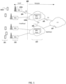
- FIG. 1 illustrates a cloud RAN 100 that includes (a) a plurality of UEs 101, one of which is designated as UE 101A, (b) a plurality of RRUs 102, one of which is designated as RRU 102A, (c) a plurality of BBU pools 103, one of which is designated as BBU pool 103A, and an evolved packet core (EPC) network 107.
- a local network comprises RRUs 102, which are connected to remote BBU pools 103 in the cloud using a fronthaul interface (FH), one of which is designated as FH 104.
- FH fronthaul interface
- RRUs 102 may have limited processing capability to send RF signals to the BBU pools 103 or may have some amount of compression to limit the traffic on the fronthaul.
- BBU pools 103 may be connected to other BBU pools 103 via an X2 interface, e.g., X2 interface 106, and connected to EPC network 107 via an S1 interface, e.g., S1 interface 105.
- the fronthaul latency is a critical component that determines the applications supported by cloud RAN 100.
- a one-way latency of ⁇ 250 microseconds ( ⁇ s), which can be supported by fiber, is typically assumed for cloud RAN systems.
- a non-ideal one-way latency would be considered as ⁇ 30 ms, while ⁇ 2 ms and ⁇ 6 ms are defined as near-ideal and sub-ideal latencies, respectively, by the SCF. Note that these are fronthaul latencies for the transport and are much stricter than the end-to-end latencies needed for the application.
- 5G networks will be built around people and things and will natively meet the requirements of three groups of use cases:
- the third application may require latencies in the order of the few milliseconds (or even shorter) at the application layer. This would be difficult to achieve in a cloud RAN, if the fronthaul is not ideal.
- MEC Mobile-edge computing
- multi-tier cloud networks To support low latency applications, various methods exist such as Mobile-edge computing (MEC) and multi-tier cloud networks.
- MEC Mobile-edge computing
- multi-tier cloud networks To support low latency applications, various methods exist such as Mobile-edge computing (MEC) and multi-tier cloud networks.
- MEC Mobile Edge Computing
- MEC is a network architecture concept that enables cloud computing capabilities and an IT service environment at the edge of the cellular network.
- the basic idea behind MEC is that by running applications and performing related processing tasks closer to the cellular customer, network congestion is reduced and applications perform better.
- MEC technology is designed to be implemented at the cellular base stations, and enables flexible and rapid deployment of new applications and services for customers. Combining elements of information technology and telecommunications networking, MEC also allows cellular operators to open their RAN to authorized third-parties, such as application developers and content providers.
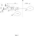
- FIG. 2 illustrates a mobile edge computing based cloud RAN 200.
- An ideal fronthaul FH 204 is assumed for the connection between an RRU 202 and a BBU pool 203 located at the network edge. Both BBU pool 203 and RRU 202 are considered local in this deployment to support low latency communication with UE 201, and BBU pool 203 is thus regarded as a local cloud RAN.
- a MEC server 205 connects BBU 203 to a local enterprise environment 206 and an EPC network 207. MEC server 205 provides computing resources, storage capacity, connectivity and access to RAN information, and supports a multitenancy run-time and hosting environment for applications.
- Another option to provide low latency support is to break the cloud RAN into multiple tiers.
- FIG. 3 illustrates a multi-tier cloud network.
- the low latency related aspects related to RAN processing for UE 301 can be handled by a local cloud RAN 303 while the less stringent aspects can be handled by a remote cloud RAN 306.
- Local cloud RAN 303 and remote cloud RAN 306 layering can provide function aggregation and statistical multiplexing gains.
- the PHY can be done in an RRU 302
- the MAC can be done in local cloud RAN 303
- the RLC/PDCP layers can be implemented in remote cloud RAN 306.
- a fronthaul interface FH-1 304 is a low latency fronthaul (near-ideal as defined above) to a BBU pool in local cloud RAN 303 where lower layer processing is performed, while a fronthaul interface FH-2 305 can be higher latency fronthaul (close to near-ideal or non-ideal as defined above) to a BBU pool in remote cloud RAN 306, where the upper layers of the protocol stack are processed.
- Remote cloud RAN 306 is connected to an EPC network 307 via an S1 interface.
- all baseband processing data is first processed by the local cloud RAN.
- the baseband computation, esp. related to layer 1 processing can form a significant portion of the resource utilization in the local cloud RAN. This implies the local cloud RAN will require deployment of significant resources to handle the processing of both latency-tolerant as well as latency-sensitive applications.
- a split cloud RAN architecture is proposed where the local cloud RAN only handles the processing of latency-sensitive applications while the latency-tolerant applications are handled by the remote cloud RAN.
- This allows the local cloud RAN to be built in a cost-effective manner with limited processing resources as it need not process latency-tolerant applications such as remote file transfer or video uploads that may be very compute intensive.
- FIG. 4 illustrates a split cloud RAN architecture where processing is split between a local cloud RAN 404 and a remote cloud RAN 408.
- a fronthaul interface FH-1 403 is an ideal fronthaul that connects RRUs 402 to local cloud RAN 404.
- a switch 405 distributes the data for further processing either in local cloud RAN 404 or in remote cloud RAN 408 depending on the requirements of the application from a UE 401, e.g., a cell phone, or a UE 410, e.g., an autonomous car.
- Remote cloud RAN 408 is connected to an EPC 409.
- the knowledge of whether UE 401 or UE 410 requests a low latency application or not can be based on several factors. For example, this could be by a low latency UE 410, e.g., an autonomous car, indicating it in its capabilities that it is supporting low latency applications, when it attaches to the network. It is also possible that UEs can dynamically select between low latency and latency-tolerant applications based on the APN, for example.
- the network attachment process is first performed by remote cloud RAN 408. Based on the requirements of UE 410 to support low latency, the processing of UE 410 is transferred to local cloud RAN 404, using fronthaul interface FH-2 407. This is done in a transparent manner to UE 410.
- Local cloud RAN 404 allocates and processes separate UL and DL resources for such UEs 410 while all other UEs 401 are handled by remote cloud RAN 408.
- a controller 406 manages the coordination of resources between local cloud RAN 404 and remote cloud RAN 408. Controller 406 takes input from a BBU in remote cloud RAN 408 to control switch 405 and organizes the transmission and reception to/from RRU 402.
- a local EPC 411 allows low latency access to local cloud RAN 404 by implementing core network functions at the local network edge.
- Local EPC 411 splits the control and user plane operations within Serving Gateway (SGW) (not shown) and Packet Data Network Gateway (PGW) (not shown) network entities. This allows user plane operations to be implemented locally, while control plane operations remain under the control of the mobile network operator (MNO) (not shown), and can be located at the edge, in the cloud, or centrally.
- SGW Serving Gateway
- PGW Packet Data Network Gateway
- MNO mobile network operator
- Local EPC 411 can also integrate the private branch exchange (PBX) capabilities for enterprise deployments without the need for configuration via the MNO.
- PBX private branch exchange
- a UE If a UE supports both latency-tolerant and latency- sensitive applications, it is given multiple connections (different APNs) and based on its connection request from the application, it is routed to a local cloud network or a remote network.
- the scheduler (not shown in FIG. 4 ) of local cloud RAN 404 and the scheduler (not shown in FIG. 4 ) of remote cloud RAN 408 need to co-operate to share time-frequency resources (e.g., to allocate bandwidth) for the cloud RAN which is handled by controller 406. All UE-specific functions are handled independently by both local cloud RAN 404 and remote cloud RAN 408. The cell-specific functions can be handled by RRU 402.
- FIG. 5 shows processing split between remote cloud and local cloud processing.
- a local cloud RAN 502 schedules the low latency applications while a remote cloud RAN 503 schedules the latency-tolerant applications.
- the time-frequency resources are shared between local cloud RAN 502 and remote cloud RAN 503 based on the scheduler interaction between local cloud RAN 502 and remote cloud RAN 503 via an FH-2 control interface 504.
- the scheduler interaction is not at a per sub-frame (1 ms) level due to the latency involved in remote cloud RAN 503 but at a slower rate, i.e., semi-static configuration, to adapt to the change in network conditions (e.g., several hundred milliseconds).
- Reference signals and synchronization signals can be generated either in local cloud RAN 502 or at remote cloud RAN 503 or at an RRU 501 itself, depending on the type of reference signal.
- Primary synchronization sequence (PSS) and secondary synchronization sequence (SSS) synchronization signals that are cell-specific can be generated at RRU 501
- demodulation reference signals (DMRS) that are user-specific can be generated in local cloud RAN 502 or remote cloud RAN 503 based on the latency requirement of the application from the UE.
- Data from remote cloud RAN 503 is sent to local cloud RAN 502 using an FH-2 data interface 505.
- Multiple RRUs can also be connected to local cloud RAN 502 using an FH-1 interface 506.
- the user specific processing in local cloud RAN 502 can consist of blocks such as modulation and precoding, the forward error correction (FEC), the hybrid automatic repeat request (HARQ) and further processing of the RAN protocol stack. Note that other splits are also possible, where more functions of the RAN protocol can be moved between local cloud RAN 502 and the RRUs.
- a switch 507 can be external to local cloud RAN 502, and can be a router, for example. Switch 507 distributes data for processing either in local cloud RAN 502 or in remote cloud RAN 503 depending on the latency requirements of an application from a UE.
- the RRU uses dedicated hardware that can process the entire PHY, it is possible to support a MAC-PHY split as the basis for the fronthaul interface FH-1.
- the UE processing from the MAC can be multiplexed to the RRU.
- the FH-1 interface to the RRU becomes similar to the nFAPI interface that is supported by the SFC.
- FIG. 6 illustrates an alternative processing split at an MAC-PHY interface between a local cloud RAN 602 and a remote cloud RAN 603.
- Local cloud RAN 602 schedules the low latency applications while remote cloud RAN 603 schedules the latency-tolerant applications.
- the time-frequency resources are shared between local cloud RAN 602 and remote cloud RAN 603 based on the scheduler interaction between local cloud RAN 602 and remote cloud RAN 603 via an FH-2 control interface 604.
- the entire PHY is processed in an RRU, e.g., RRU 601.
- Data from remote cloud RAN 603 is sent to local cloud RAN 602 using an FH-2 data interface 605.
- Multiple RRUs can also be connected to local cloud RAN 602 using an FH-1 interface 606.
- 5G also supports network slicing, where low latency applications may use different OFDM numerologies than latency-tolerant applications.
- the latency-sensitive application may use a different transmission time interval (TTI) and use a different sub-carrier spacing and FFT sizes, compared to the latency-tolerant application.
- TTI transmission time interval
- FFT FFT size
- FIG. 7 shows a split between local and remote cloud processing using different numerologies.
- the entire PHY and MAC processing can be different between a local cloud RAN 702 and a remote cloud RAN 703.
- the frame structure (transmission time intervals), OFDM numerology such as sub-carrier spacing, bandwidth, etc. could be different between local cloud RAN 702 and a remote cloud RAN 703.
- an RRU 701 has very limited functionality related to critical timing related features and compression of a fronthaul interface FH-1 706 while most of the processing for the PHY and MAC is performed differently in local cloud RAN 702 and remote cloud RAN 703 based on the numerology adapted for the application.
- Time-frequency resources are shared between local cloud RAN 702 and remote cloud RAN 703 based on scheduler interaction between local cloud RAN 702 and remote cloud RAN 703 via an FH-2 control interface 704.
- Data from remote cloud RAN 703 is sent to local cloud RAN 702 using an FH-2 data interface 705.
- Multiple RRUs can also be connected to local cloud RAN 702 using an FH-1 interface 706.
- the local cloud RAN may overlap its resources with the remote cloud RAN, where the overlap is designed such that the remote cloud RAN resources may still operate with reduced functionality (e.g., punctured or transmitted at very low power) in the common region.
- the local cloud RAN tries to negotiate resources with the remote cloud RAN for resource management.
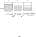
- FIG. 8 illustrates time-frequency (TF) resources (e.g., a time resource and/or a bandwidth or frequency resource) being shared between local and remote cloud processing.
- TF time-frequency
- allocation of a frequency resource means allocation of a frequency or a bandwidth.
- the allocation of resources could be done by an independent controller, which takes the input of both BBUs, or done by one of the BBUs (i.e., master/slave setting).
- Section (A) shows a partitioning of resources at time instant T1.
- a remote cloud RAN allocates resources 801 for its UEs while allowing resources 802 for processing latency-sensitive UEs.
- Resource utilization information for local cloud RAN UEs is then transferred to the remote cloud RAN on a periodic basis or per request. If the resources used exceed a threshold, the remote cloud RAN may re-adjust its resource allocation to allow greater resources for the local processing.
- Section (B) shows a dynamic change in partitioning at time instant T2 (T2 > T1) after resource re-negotiation. It is also possible that there could be certain latency-sensitive UEs that may need immediate allocation without any time for re-negotiation.
- the local cloud RAN may schedule transmissions on resources overlapped with the remote cloud RAN in a certain region 803.
- the remote cloud RAN transmission in region 803 is designed such that it can accommodate overlapping transmissions (or work under high interference conditions).
- Section (C) shows an overlapped transmission at time instant T3 (T3 > T2), where there is no time to negotiate for resources for some mission-critical applications.
- the X and Y axis in FIG. 8 could represent time and frequency resources or vice-versa.
- FIG. 9 illustrates a time-frequency resource negotiation procedure between a local cloud RAN and a remote cloud RAN.
- the remote cloud RAN acts as a master to define a frequency allocation.
- the local cloud RAN periodically (or upon request) reports its resource utilization to the remote cloud RAN. If the local cloud RAN resource utilization is above a first threshold or below a second threshold, for example, the remote cloud RAN will adjust its scheduling resources to increase or decrease its resources and inform the local cloud RAN of the change.
- the present disclosure provides a method and a system to handle low latency without overburdening the local cloud RAN to support the entire BBU processing for all applications.
- a split cloud radio access network (RAN) architecture where RAN processing is split between a local cloud RAN and a remote cloud RAN with a non-ideal fronthaul, where the local cloud RAN processes only latency-sensitive applications, and the remote cloud RAN processes latency-tolerant applications.
- RAN radio access network
- a method for coordinating scheduling of latency-sensitive and latency-tolerant UEs where the remote cloud RAN scheduler informs the local cloud RAN scheduler of the available time/frequency resources for scheduling the latency-sensitive UEs, and the local cloud RAN scheduler independently schedules the latency-sensitive UEs, based on the provided time/frequency resources.
- a split cloud RAN architecture where the user level processing is done either in the remote or local cloud based on the latency-sensitive application, while the cell level processing is done at the RRU.
- a split cloud RAN architecture where both the local and remote clouds process the MAC and upper layers, while the PHY layer is implemented at the RRU.
- a split cloud RAN architecture where the local cloud implements a waveform numerology optimized for low latency applications, while the remote cloud implements a different waveform numerology that is more suitable for latency-tolerant applications.
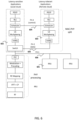
- FIG. 10 is a block diagram of a processing apparatus 1000, e.g., a computer, that may be included as a component of a BBU, an RRU, an MEC server, a controller, or other device, to perform the processing activities described herein.
- Processing apparatus 1000 includes a processor 1005, a memory 1010, and a network interface 1020.
- processor 1005 a processor 1005
- memory 1010 a memory 1010
- network interface 1020 e.g., a network interface
- Processor 1005 is an electronic device configured of logic circuitry that responds to and executes instructions.
- Memory 1010 is a tangible, non-transitory, computer-readable storage device encoded with a computer program.
- memory 1010 stores data and instructions, i.e., program code, that are readable and executable by processor 1005 for controlling the operation of processor 1005.
- Memory 1010 may be implemented in a random access memory (RAM), a hard drive, a read only memory (ROM), or a combination thereof.
- One of the components of memory 1010 is a program module 1015.
- Program module 1015 contains instructions for controlling processor 1005 to execute the various methods and processes described herein.
- module is used herein to denote a functional operation that may be embodied either as a stand-alone component or as an integrated configuration of a plurality of subordinate components.
- program module 1015 may be implemented as a single module or as a plurality of modules that operate in cooperation with one another.
- program module 1015 is described herein as being installed in memory 1010, and therefore being implemented in software, it could be implemented in any of hardware (e.g., electronic circuitry), firmware, software, or a combination thereof.
- Network interface 1020 is an electronic circuit through which processing apparatus 1000 communicates with other devices in the various networks described herein.
- Storage device 1025 is a tangible, non-transitory, computer-readable storage device that stores program module 1015 thereon.
- Examples of storage device 1025 include (a) a compact disk, (b) a magnetic tape, (c) a read only memory, (d) an optical storage medium, (e) a hard drive, (f) a memory unit consisting of multiple parallel hard drives, (g) a universal serial bus (USB) flash drive, (h) a random access memory, and (i) an electronic storage device that is coupled to processing apparatus 1000 via a data communication network, e.g., the Internet.
- a data communication network e.g., the Internet.
- FIG. 11 shows how the principles described herein can be extended to a 5G system where the BBU can be split into a CU (Central Unit) and a DU (Distributed Unit).
- UEs 1101A and 1101B support both 4G and 5G.
- RRUs 1102 are connected to a local cloud RAN 1104 via fronthaul interfaces FH-1 1103.
- Local cloud RAN 1104 includes a controller 1106, a switch 1105, and a 5G BBU DU + CU Pool 1114, and is connected to a local EPC 1113.
- 5G BBU DU + CU pool 1114 is used for low latency application processing for a data plane while control plane procedures for mobility are handled by a 4G BBU pool 1109.
- high data rate but latency-tolerant applications e.g., file download
- 5G CU pool 1111 is connected to 4G pool 1109 via an Xn interface, which is defined in 3GPP for the dual connectivity mode (non-standalone deployment for 5G).
- the resource sharing for the 5G network between the local 5G BBU DU+CU pool 1114 and remote 5G DU pool 1110 and remote 5G CU pool 1111 can be done similarly to the procedure explained above with reference to FIG. 8 .
- controller 1106 controls switch 1105 to distribute data for processing either (a) in local cloud RAN 1104, by 5G BBU DU + CU pool 1114, or (b) in remote cloud RAN 408, by either 4G BBU pool 1109 or 5G DU pool 1110 + 5G CU pool 1111.
- Switch 1105 is connected to 4G BBU pool 1109 by a fronthaul interface FH-2 1107, and connected to 5G DU pool 1110 by a fronthaul interface FH-3 1108.
Description
- The present disclosure relates to wireless communication systems targeted towards a radio access network (RAN) that is implemented in a distributed manner where parts of the RAN processing are performed at a cell site or tower while the rest of the RAN processing can be performed remotely in data centers in the cloud, i.e., a cloud RAN (C-RAN).
- The approaches described in this section are approaches that could be pursued, but not necessarily approaches that have been previously conceived or pursued. Therefore, the approaches described in this section may not be prior art to the present disclosure and are not admitted being prior art by inclusion in this section.
- Cloud RAN provides centralization and virtualization of a RAN, leading to benefits such as (a) operation cost reduction due to resource pooling and running the RAN on general-purpose hardware, enabling economies of scale, (b) performance improvements due to better interference management, (c) remote upgradeability and management of the RAN and (d) simpler migration to add new features and transition from 4G to 5G networks. An example of cloud RAN is provided in
US 2013/017852 A1 . - Traditional RANs implement the protocol stack (e.g., Physical Layer (PHY), Medium Access Control (MAC), Radio Link Control (RLC), Packet Data Convergence Control (PDCP layers)) at a base-station (also referred to as an eNodeB). In cloud RAN, different radio functions are split between a remote radio unit (RRU) and a baseband unit (BBU). The RRU is implemented locally onsite, while the BBU is virtualized on the cloud, which could be tens or hundreds of miles away from the RRU. A single BBU (or vRAN) can control multiples of RRUs in different locations.
- One split scenario between the BBU and the RRU, for example, is to split the protocol stack at the PHY layer, where the Radio Frequency (RF) operation and lower PHY functions (e.g., orthogonal frequency division multiplexing (OFDM) modulation for downlink (DL): inverse fast Fourier transform (IFFT), cyclic prefix (CP) addition, and OFDM demodulation for uplink (UL): fast Fourier transform (FFT), CP removal) are executed at the RRU. On the other hand, the rest of the RAN functions (e.g., Turbo encoding/decoding, bit interleaving/scrambling, channel estimation, equalization, scheduler, etc.) are done at the cloud.
- Various options exist for the fronthaul connection between the BBU and the RRU such as using Ethernet, fiber, etc. This fronthaul communication, which is crucial for data and control communications between the RRU and the BBU, adds additional delay for cloud RAN systems.
- One of the main challenges in centralization of the processing is meeting the latency requirement imposed by the RAN processing. This problem is exacerbated by a new class of low latency applications being considered for 5G communication systems, requiring support for sub-millisecond latency, making remote processing difficult if not impossible for such applications. Examples of such systems include industry automation, self-driving cars and mission-critical applications.
- Low latency applications for cloud RAN are typically handled by running the RAN and core protocol stacks at the edge of the network, where the RRUs and BBU are located locally along with the core network for local offloading and processing of data traffic. Mobile-Edge Computing (MEC) offers application developers and content providers cloud-computing capabilities and an IT (information technology) service environment at the edge of the mobile network. This environment is characterized by ultra-low latency and high bandwidth as well as real-time access to radio network information that can be leveraged by applications.
- Another similar approach which has been proposed for low latency support is fog computing. Fog computing uses one or more collaborative multitude of end-user clients or near-user edge devices to carry out a substantial amount of storage (rather than stored primarily in cloud data centers), communication (rather than routed over the Internet backbone), control, configuration, measurement and management (rather than controlled primarily by network gateways such as those in the Long-Term Evolution (LTE) core network).
- The limitation of such systems is that not all network applications require such low latency support, leading to overprovisioning of the local cloud RAN and increased costs.
- SUMMARY OF THE DISCLOSURE The invention provides a system and a method in accordance with the independent claims. Preferred embodiments are defined in the dependent claims. The following is provided as useful for understanding the context of the invention.
- There is provided a system that includes a local cloud radio access network (RAN), and a remote cloud RAN having a non-ideal fronthaul. The local cloud RAN processes latency-sensitive applications, and the remote cloud RAN processes latency-tolerant applications.
- The local cloud RAN has a local scheduler. The remote cloud RAN has a remote scheduler. The remote scheduler informs the local scheduler of available time/frequency resources for scheduling latency-sensitive user equipment. The local scheduler schedules the latency-sensitive user equipment based on the available time/frequency resources.
- The local cloud RAN has currently available resources for supporting latency critical applications, and informs the remote cloud RAN of said currently available resources. The remote cloud RAN adjusts a resource allocation split between the local cloud RAN and the remote cloud RAN.
- The system may also include a remote radio unit that performs cell level processing.
- The system may also include a remote radio unit at which is implemented a physical layer of a protocol stack. The local cloud RAN and the remote cloud RAN process medium access control and upper layers of the protocol stack.
- The local cloud RAN implements a first waveform numerology optimized for the latency-sensitive applications. The remote cloud RAN implements a second waveform numerology optimized for the latency-tolerant applications.
- The latency-sensitive applications may require a latency of less than 10 milliseconds. The latency-tolerant applications can tolerate a latency of greater than 30 milliseconds. These numbers are provided as examples and not a limitation of this disclosure.
-
-
FIG. 1 illustrates a cloud RAN. -
FIG. 2 illustrates a mobile edge computing based cloud RAN. -
FIG. 3 illustrates a multi-tier cloud RAN. -
FIG. 4 illustrates a split cloud RAN architecture where processing is split between a local cloud RAN and a remote cloud RAN. -
FIG. 5 illustrates processing split between remote cloud and local cloud processing. -
FIG. 6 illustrates an alternative processing split at the MAC-PHY interface between a local cloud and a remote cloud. -
FIG. 7 illustrates a split between local and remote cloud processing using different numerologies. -
FIG. 8 illustrates time-frequency (TF) resources being shared between local and remote cloud processing. -
FIG. 9 illustrates a time-frequency resource negotiation procedure between local and remote clouds. -
FIG. 10 is a block diagram of a processing apparatus. -
FIG. 11 illustrates a split cloud RAN architecture for a 5G system. - A component or a feature that is common to more than one drawing is indicated with the same reference number in each of the drawings.
- The present disclosure provides a technique to handle low latency applications for cloud RAN systems by supporting both a local cloud RAN with limited resources that is used only for low latency applications (e.g., latency < 10 milliseconds (ms)) while a remote cloud RAN handles latency-tolerant applications (e.g., latency > 10 ms). The user traffic is appropriately routed to the correct cloud RAN based on the application. The user equipment (UE) has no knowledge of which network has been used for processing, i.e., this network processing split is done in a manner that is transparent to the UE, for example, by dynamically selecting a different access point name (APN) for local vs. remote processing. The processing split of the RAN between the local cloud RAN and the remote cloud RAN is done in a dynamic manner depending on the number of devices requiring low latency support. This allows the local cloud RAN to be very compact and low-cost since it does not have to process the latency-tolerant traffic.
-
FIGS. 1 through 11 , discussed below, and the various embodiments used to describe the principles of the present disclosure are by way of illustration only and should not be construed in any way to limit the scope of the disclosure. Those skilled in the art will understand that the principles of the present disclosure may be implemented in any suitably arranged system or device. - The femto application platform interface nFAPI and FAPI specification document SCF082, defined by the Small Cell Forum (SFC) is acknowledged here. The SCF is a forum that promotes small cell adoption to change the shape of mobile networks and maximize the potential of mobile services.
- Mobile networks are evolving quickly in terms of coverage, capacity and new features, continuously pushed by new requirements relating to latency, traffic volumes and data rates.
- A RAN is the equipment that connects to cellular antennas, processes the signal and sends it to the core network. As the demand for connectivity has exploded, mobile operators have looked for ways to minimize the footprint and cost of their equipment. This has led to the move to centralize parts of the RAN. Specifically, a BBU is the part of the RAN that carriers may move to a central location from which multiple RRUs can be served. Fiber is typically used to connect BBUs to RRUs, and this connection is often referred to as "fronthaul" as opposed to backhaul, which refers to the connection of the RAN to the core network. In some architectures, the BBUs are linked and can share information, and in others they are simply located in the same area. Cloud RAN implies that the baseband processing is handled primarily in software and is run on a generic "white box" server in the cloud. By introducing cloud RAN architectures, operators will be able to meet accelerating demands of cellular networks through the use of Network Functions Virtualization (NFV) techniques and data center processing capabilities in their networks, which allows for resource pooling, scalability, layer interworking and spectral efficiency.
- In some cases, a BBU is also known as a Central Unit (CU) that processes data and an RRU is known as a Distributed Unit (DU). The RRU may also be denoted as a remote radio head (RRH) in some cases. In other cases, for 5G, the BBU is split into CU and DU while the RRH is referred to as a transmit-receive point (TRP). In some cases, the BBU implementation is referred to as a Virtual Network Function (VNF) while the RRU implementation is referred to as a Physical Network Function (PNF).
-
FIG. 1 illustrates acloud RAN 100 that includes (a) a plurality ofUEs 101, one of which is designated asUE 101A, (b) a plurality ofRRUs 102, one of which is designated asRRU 102A, (c) a plurality ofBBU pools 103, one of which is designated asBBU pool 103A, and an evolved packet core (EPC)network 107. A local network comprisesRRUs 102, which are connected to remote BBU pools 103 in the cloud using a fronthaul interface (FH), one of which is designated asFH 104. Here, "local" refers to a very short distance from the RRUs 102 (such at the same cell site or at the edge of a enterprise network, typically 10-100's of meters), while "remote" refers to a longer distance, e.g., one or more kilometers, from the RRU.RRUs 102 may have limited processing capability to send RF signals to the BBU pools 103 or may have some amount of compression to limit the traffic on the fronthaul. BBU pools 103 may be connected toother BBU pools 103 via an X2 interface, e.g.,X2 interface 106, and connected toEPC network 107 via an S1 interface, e.g.,S1 interface 105. - The fronthaul latency is a critical component that determines the applications supported by
cloud RAN 100. A one-way latency of < 250 microseconds (µs), which can be supported by fiber, is typically assumed for cloud RAN systems. A non-ideal one-way latency would be considered as < 30 ms, while < 2 ms and < 6 ms are defined as near-ideal and sub-ideal latencies, respectively, by the SCF. Note that these are fronthaul latencies for the transport and are much stricter than the end-to-end latencies needed for the application. - 5G networks will be built around people and things and will natively meet the requirements of three groups of use cases:
- 1. Enhanced Mobile broadband (eMBB) that delivers gigabytes of bandwidth on demand.
- 2. Massive machine-type communication (mMTC) that connects billions of sensors and machines.
- 3. Ultra-reliable and low latency communication (URLLC) for applications with high reliability and low latency constraints and enables, for example, remote control over robots and autonomous driving.
- While the first two classes of applications can tolerate latency, the third application may require latencies in the order of the few milliseconds (or even shorter) at the application layer. This would be difficult to achieve in a cloud RAN, if the fronthaul is not ideal.
- To support low latency applications, various methods exist such as Mobile-edge computing (MEC) and multi-tier cloud networks.
- One method to support low latency applications is by moving the RAN processing (compute) to the edge of the network. Mobile Edge Computing (MEC) is a network architecture concept that enables cloud computing capabilities and an IT service environment at the edge of the cellular network. The basic idea behind MEC is that by running applications and performing related processing tasks closer to the cellular customer, network congestion is reduced and applications perform better. MEC technology is designed to be implemented at the cellular base stations, and enables flexible and rapid deployment of new applications and services for customers. Combining elements of information technology and telecommunications networking, MEC also allows cellular operators to open their RAN to authorized third-parties, such as application developers and content providers.
-
FIG. 2 illustrates a mobile edge computing basedcloud RAN 200. Anideal fronthaul FH 204 is assumed for the connection between anRRU 202 and aBBU pool 203 located at the network edge. BothBBU pool 203 andRRU 202 are considered local in this deployment to support low latency communication withUE 201, andBBU pool 203 is thus regarded as a local cloud RAN. AMEC server 205 connectsBBU 203 to alocal enterprise environment 206 and anEPC network 207.MEC server 205 provides computing resources, storage capacity, connectivity and access to RAN information, and supports a multitenancy run-time and hosting environment for applications. - Another option to provide low latency support is to break the cloud RAN into multiple tiers.
-
FIG. 3 illustrates a multi-tier cloud network. The low latency related aspects related to RAN processing forUE 301 can be handled by alocal cloud RAN 303 while the less stringent aspects can be handled by aremote cloud RAN 306.Local cloud RAN 303 andremote cloud RAN 306 layering can provide function aggregation and statistical multiplexing gains. For example, the PHY can be done in anRRU 302, the MAC can be done inlocal cloud RAN 303 and the RLC/PDCP layers can be implemented inremote cloud RAN 306. A fronthaul interface FH-1 304 is a low latency fronthaul (near-ideal as defined above) to a BBU pool inlocal cloud RAN 303 where lower layer processing is performed, while a fronthaul interface FH-2 305 can be higher latency fronthaul (close to near-ideal or non-ideal as defined above) to a BBU pool inremote cloud RAN 306, where the upper layers of the protocol stack are processed.Remote cloud RAN 306 is connected to anEPC network 307 via an S1 interface. - In the approaches discussed in
FIG. 2 andFIG. 3 , all baseband processing data is first processed by the local cloud RAN. The baseband computation, esp. related tolayer 1 processing can form a significant portion of the resource utilization in the local cloud RAN. This implies the local cloud RAN will require deployment of significant resources to handle the processing of both latency-tolerant as well as latency-sensitive applications. - In the present disclosure, a split cloud RAN architecture is proposed where the local cloud RAN only handles the processing of latency-sensitive applications while the latency-tolerant applications are handled by the remote cloud RAN. This allows the local cloud RAN to be built in a cost-effective manner with limited processing resources as it need not process latency-tolerant applications such as remote file transfer or video uploads that may be very compute intensive.
-
FIG. 4 illustrates a split cloud RAN architecture where processing is split between alocal cloud RAN 404 and aremote cloud RAN 408. A fronthaul interface FH-1 403 is an ideal fronthaul that connectsRRUs 402 tolocal cloud RAN 404. Once data reacheslocal cloud RAN 404, aswitch 405 distributes the data for further processing either inlocal cloud RAN 404 or inremote cloud RAN 408 depending on the requirements of the application from aUE 401, e.g., a cell phone, or aUE 410, e.g., an autonomous car.Remote cloud RAN 408 is connected to anEPC 409. - The knowledge of whether
UE 401 orUE 410 requests a low latency application or not can be based on several factors. For example, this could be by alow latency UE 410, e.g., an autonomous car, indicating it in its capabilities that it is supporting low latency applications, when it attaches to the network. It is also possible that UEs can dynamically select between low latency and latency-tolerant applications based on the APN, for example. The network attachment process is first performed byremote cloud RAN 408. Based on the requirements ofUE 410 to support low latency, the processing ofUE 410 is transferred tolocal cloud RAN 404, using fronthaul interface FH-2 407. This is done in a transparent manner toUE 410.Local cloud RAN 404 allocates and processes separate UL and DL resources forsuch UEs 410 while allother UEs 401 are handled byremote cloud RAN 408. Acontroller 406 manages the coordination of resources betweenlocal cloud RAN 404 andremote cloud RAN 408.Controller 406 takes input from a BBU inremote cloud RAN 408 to controlswitch 405 and organizes the transmission and reception to/fromRRU 402. - This controller function can be done at a BBU in
local cloud RAN 404 since it is near to the RRU 402 (i.e., almost ideal fronthaul delay, e.g., < 250 µs). Alocal EPC 411 allows low latency access tolocal cloud RAN 404 by implementing core network functions at the local network edge.Local EPC 411 splits the control and user plane operations within Serving Gateway (SGW) (not shown) and Packet Data Network Gateway (PGW) (not shown) network entities. This allows user plane operations to be implemented locally, while control plane operations remain under the control of the mobile network operator (MNO) (not shown), and can be located at the edge, in the cloud, or centrally.Local EPC 411 can also integrate the private branch exchange (PBX) capabilities for enterprise deployments without the need for configuration via the MNO. - If a UE supports both latency-tolerant and latency- sensitive applications, it is given multiple connections (different APNs) and based on its connection request from the application, it is routed to a local cloud network or a remote network.
- The scheduler (not shown in
FIG. 4 ) oflocal cloud RAN 404 and the scheduler (not shown inFIG. 4 ) ofremote cloud RAN 408 need to co-operate to share time-frequency resources (e.g., to allocate bandwidth) for the cloud RAN which is handled bycontroller 406. All UE-specific functions are handled independently by bothlocal cloud RAN 404 andremote cloud RAN 408. The cell-specific functions can be handled byRRU 402. -
FIG. 5 shows processing split between remote cloud and local cloud processing. Alocal cloud RAN 502 schedules the low latency applications while aremote cloud RAN 503 schedules the latency-tolerant applications. The time-frequency resources are shared betweenlocal cloud RAN 502 andremote cloud RAN 503 based on the scheduler interaction betweenlocal cloud RAN 502 andremote cloud RAN 503 via an FH-2control interface 504. The scheduler interaction is not at a per sub-frame (1 ms) level due to the latency involved inremote cloud RAN 503 but at a slower rate, i.e., semi-static configuration, to adapt to the change in network conditions (e.g., several hundred milliseconds). Reference signals and synchronization signals can be generated either inlocal cloud RAN 502 or atremote cloud RAN 503 or at anRRU 501 itself, depending on the type of reference signal. For example, Primary synchronization sequence (PSS) and secondary synchronization sequence (SSS) synchronization signals that are cell-specific can be generated atRRU 501, while demodulation reference signals (DMRS) that are user-specific can be generated inlocal cloud RAN 502 orremote cloud RAN 503 based on the latency requirement of the application from the UE. Data fromremote cloud RAN 503 is sent tolocal cloud RAN 502 using an FH-2data interface 505. Multiple RRUs can also be connected tolocal cloud RAN 502 using an FH-1interface 506. The user specific processing inlocal cloud RAN 502 can consist of blocks such as modulation and precoding, the forward error correction (FEC), the hybrid automatic repeat request (HARQ) and further processing of the RAN protocol stack. Note that other splits are also possible, where more functions of the RAN protocol can be moved betweenlocal cloud RAN 502 and the RRUs. Also, a switch 507 can be external tolocal cloud RAN 502, and can be a router, for example. Switch 507 distributes data for processing either inlocal cloud RAN 502 or inremote cloud RAN 503 depending on the latency requirements of an application from a UE. - In case the RRU uses dedicated hardware that can process the entire PHY, it is possible to support a MAC-PHY split as the basis for the fronthaul interface FH-1. In this case, the UE processing from the MAC can be multiplexed to the RRU. In this case, the FH-1 interface to the RRU becomes similar to the nFAPI interface that is supported by the SFC.
-
FIG. 6 illustrates an alternative processing split at an MAC-PHY interface between alocal cloud RAN 602 and aremote cloud RAN 603.Local cloud RAN 602 schedules the low latency applications whileremote cloud RAN 603 schedules the latency-tolerant applications. The time-frequency resources are shared betweenlocal cloud RAN 602 andremote cloud RAN 603 based on the scheduler interaction betweenlocal cloud RAN 602 andremote cloud RAN 603 via an FH-2control interface 604. In this case, the entire PHY is processed in an RRU, e.g.,RRU 601. Data fromremote cloud RAN 603 is sent tolocal cloud RAN 602 using an FH-2data interface 605. Multiple RRUs can also be connected tolocal cloud RAN 602 using an FH-1interface 606. - 5G also supports network slicing, where low latency applications may use different OFDM numerologies than latency-tolerant applications. For example, the latency-sensitive application may use a different transmission time interval (TTI) and use a different sub-carrier spacing and FFT sizes, compared to the latency-tolerant application. In this case, the entire PHY could be different for the local cloud RAN and the remote cloud RAN. This feature can be used to support network slicing, where the remote cloud RAN and the local cloud RAN operate differently with different parameters and numerology based on the application.
-
FIG. 7 shows a split between local and remote cloud processing using different numerologies. In this case, the entire PHY and MAC processing can be different between alocal cloud RAN 702 and aremote cloud RAN 703. For example, the frame structure (transmission time intervals), OFDM numerology such as sub-carrier spacing, bandwidth, etc. could be different betweenlocal cloud RAN 702 and aremote cloud RAN 703. In this case, anRRU 701 has very limited functionality related to critical timing related features and compression of a fronthaul interface FH-1 706 while most of the processing for the PHY and MAC is performed differently inlocal cloud RAN 702 andremote cloud RAN 703 based on the numerology adapted for the application. Time-frequency resources are shared betweenlocal cloud RAN 702 andremote cloud RAN 703 based on scheduler interaction betweenlocal cloud RAN 702 andremote cloud RAN 703 via an FH-2control interface 704. Data fromremote cloud RAN 703 is sent tolocal cloud RAN 702 using an FH-2data interface 705. Multiple RRUs can also be connected tolocal cloud RAN 702 using an FH-1interface 706. - In some latency-critical applications for 5G, it is possible that there is insufficient time for resource negotiation at the scheduler. In such cases, the local cloud RAN may overlap its resources with the remote cloud RAN, where the overlap is designed such that the remote cloud RAN resources may still operate with reduced functionality (e.g., punctured or transmitted at very low power) in the common region. In cases, when possible, the local cloud RAN tries to negotiate resources with the remote cloud RAN for resource management.
-
FIG. 8 illustrates time-frequency (TF) resources (e.g., a time resource and/or a bandwidth or frequency resource) being shared between local and remote cloud processing. For example, allocation of a frequency resource means allocation of a frequency or a bandwidth. There is a predefined (but adaptive) allocation of resources between local and remote BBUs (i.e., a BBU in the local cloud RAN, and a BBU in the remote cloud RAN). The allocation of resources could be done by an independent controller, which takes the input of both BBUs, or done by one of the BBUs (i.e., master/slave setting). Section (A) shows a partitioning of resources at time instant T1. In this case, a remote cloud RAN allocatesresources 801 for its UEs while allowingresources 802 for processing latency-sensitive UEs. Resource utilization information for local cloud RAN UEs is then transferred to the remote cloud RAN on a periodic basis or per request. If the resources used exceed a threshold, the remote cloud RAN may re-adjust its resource allocation to allow greater resources for the local processing. Section (B) shows a dynamic change in partitioning at time instant T2 (T2 > T1) after resource re-negotiation. It is also possible that there could be certain latency-sensitive UEs that may need immediate allocation without any time for re-negotiation. In such cases, the local cloud RAN may schedule transmissions on resources overlapped with the remote cloud RAN in acertain region 803. The remote cloud RAN transmission inregion 803 is designed such that it can accommodate overlapping transmissions (or work under high interference conditions). Section (C) shows an overlapped transmission at time instant T3 (T3 > T2), where there is no time to negotiate for resources for some mission-critical applications. The X and Y axis inFIG. 8 could represent time and frequency resources or vice-versa. - It is possible to split the resources in the frequency domain between the local cloud RAN and remote cloud RAN to keep the scheduling simple between the local cloud RAN and remote cloud RAN and also to allow for variable delay in the remote cloud RAN.
-
FIG. 9 illustrates a time-frequency resource negotiation procedure between a local cloud RAN and a remote cloud RAN. In order to schedule resources, the remote cloud RAN acts as a master to define a frequency allocation. The local cloud RAN periodically (or upon request) reports its resource utilization to the remote cloud RAN. If the local cloud RAN resource utilization is above a first threshold or below a second threshold, for example, the remote cloud RAN will adjust its scheduling resources to increase or decrease its resources and inform the local cloud RAN of the change. - Supporting low latency applications will be one of the critical features for cloud RAN systems. The present disclosure provides a method and a system to handle low latency without overburdening the local cloud RAN to support the entire BBU processing for all applications.
- The present document discloses the following features:
A split cloud radio access network (RAN) architecture, where RAN processing is split between a local cloud RAN and a remote cloud RAN with a non-ideal fronthaul, where the local cloud RAN processes only latency-sensitive applications, and the remote cloud RAN processes latency-tolerant applications. - A method for coordinating scheduling of latency-sensitive and latency-tolerant UEs, where the remote cloud RAN scheduler informs the local cloud RAN scheduler of the available time/frequency resources for scheduling the latency-sensitive UEs, and the local cloud RAN scheduler independently schedules the latency-sensitive UEs, based on the provided time/frequency resources.
- A method for coordinating the scheduling where the local cloud informs the remote cloud of its current resource usage for supporting latency critical applications, which is used by the remote cloud to adjust the resource allocation split between the local and remote cloud.
- A split cloud RAN architecture, where the user level processing is done either in the remote or local cloud based on the latency-sensitive application, while the cell level processing is done at the RRU.
- A split cloud RAN architecture, where both the local and remote clouds process the MAC and upper layers, while the PHY layer is implemented at the RRU.
- A split cloud RAN architecture, where the local cloud implements a waveform numerology optimized for low latency applications, while the remote cloud implements a different waveform numerology that is more suitable for latency-tolerant applications.
-
FIG. 10 is a block diagram of aprocessing apparatus 1000, e.g., a computer, that may be included as a component of a BBU, an RRU, an MEC server, a controller, or other device, to perform the processing activities described herein.Processing apparatus 1000 includes aprocessor 1005, amemory 1010, and anetwork interface 1020. Althoughprocessing apparatus 1000 is represented herein as a standalone device, it is not limited to such, but instead can be coupled to other devices (not shown) in a distributed processing system. -
Processor 1005 is an electronic device configured of logic circuitry that responds to and executes instructions. -
Memory 1010 is a tangible, non-transitory, computer-readable storage device encoded with a computer program. In this regard,memory 1010 stores data and instructions, i.e., program code, that are readable and executable byprocessor 1005 for controlling the operation ofprocessor 1005.Memory 1010 may be implemented in a random access memory (RAM), a hard drive, a read only memory (ROM), or a combination thereof. One of the components ofmemory 1010 is aprogram module 1015. -
Program module 1015 contains instructions for controllingprocessor 1005 to execute the various methods and processes described herein. The term "module" is used herein to denote a functional operation that may be embodied either as a stand-alone component or as an integrated configuration of a plurality of subordinate components. Thus,program module 1015 may be implemented as a single module or as a plurality of modules that operate in cooperation with one another. Moreover, althoughprogram module 1015 is described herein as being installed inmemory 1010, and therefore being implemented in software, it could be implemented in any of hardware (e.g., electronic circuitry), firmware, software, or a combination thereof. -
Network interface 1020 is an electronic circuit through whichprocessing apparatus 1000 communicates with other devices in the various networks described herein. - While
program module 1015 is indicated as being already loaded intomemory 1010, it may be configured on astorage device 1025 for subsequent loading intomemory 1010.Storage device 1025 is a tangible, non-transitory, computer-readable storage device that storesprogram module 1015 thereon. Examples ofstorage device 1025 include (a) a compact disk, (b) a magnetic tape, (c) a read only memory, (d) an optical storage medium, (e) a hard drive, (f) a memory unit consisting of multiple parallel hard drives, (g) a universal serial bus (USB) flash drive, (h) a random access memory, and (i) an electronic storage device that is coupled toprocessing apparatus 1000 via a data communication network, e.g., the Internet. -
FIG. 11 shows how the principles described herein can be extended to a 5G system where the BBU can be split into a CU (Central Unit) and a DU (Distributed Unit).UEs 1101A and 1101B support both 4G and 5G.RRUs 1102 are connected to alocal cloud RAN 1104 via fronthaul interfaces FH-1 1103.Local cloud RAN 1104 includes acontroller 1106, aswitch 1105, and a 5G BBU DU +CU Pool 1114, and is connected to alocal EPC 1113. - UE attach and mobility procedures are handled by a remote
4G BBU pool 1109 and aremote EPC 1112. 5G BBU DU +CU pool 1114 is used for low latency application processing for a data plane while control plane procedures for mobility are handled by a4G BBU pool 1109. In addition, high data rate but latency-tolerant applications (e.g., file download) can be handled by a 5G DU pool 1110 and a5G CU pool 1111.5G CU pool 1111 is connected to4G pool 1109 via an Xn interface, which is defined in 3GPP for the dual connectivity mode (non-standalone deployment for 5G). The resource sharing for the 5G network between the local 5G BBU DU+CU pool 1114 and remote 5G DU pool 1110 and remote5G CU pool 1111 can be done similarly to the procedure explained above with reference toFIG. 8 . - Depending on the requirements of the applications from
UE 1101A and 1101B,controller 1106 controls switch 1105 to distribute data for processing either (a) inlocal cloud RAN 1104, by 5G BBU DU +CU pool 1114, or (b) inremote cloud RAN 408, by either4G BBU pool 5G CU pool 1111.Switch 1105 is connected to4G BBU pool 1109 by a fronthaul interface FH-2 1107, and connected to 5G DU pool 1110 by a fronthaul interface FH-3 1108. - The techniques described herein are exemplary, and should not be construed as implying any particular limitation on the present disclosure. It should be understood that various alternatives, combinations and modifications could be devised by those skilled in the art. For example, steps associated with the processes described herein can be performed in any order, unless otherwise specified or dictated by the steps themselves. The present disclosure is intended to embrace all such alternatives, modifications and variances.
- The terms "comprises" or "comprising" are to be interpreted as specifying the presence of the stated features, integers, steps or components, but not precluding the presence of one or more other features, integers, steps or components or groups thereof. The terms "a" and "an" are indefinite articles, and as such, do not preclude embodiments having pluralities of articles.
- Definitions of acronyms and abbreviations used herein:
- 4G
- fourth generation of broadband cellular technology
- 5G
- fifth generation of broadband cellular technology
- APN
- access point name
- BBU
- baseband unit
- CP
- cyclic prefix
- C-RAN
- cloud radio access network
- CU
- central unit
- DL
- downlink
- DMRS
- demodulation reference signals
- DU
- distributed unit
- eMBB
- Enhanced Mobile Broadband
- EPC
- evolved packet core
- FEC
- forward error correction
- FFT
- fast Fourier transform
- FH
- fronthaul
- HARQ
- hybrid automatic repeat request
- IFFT
- inverse fast Fourier transform
- IT
- information technology
- LTE
- Long-Term Evolution
- MAC
- Medium Access Control
- MEC
- Mobile-Edge Computing
- mMTC
- Massive machine-type communication
- MNO
- mobile network operator
- NFV
- Network Functions Virtualization
- OFDM
- orthogonal frequency-division multiplexing
- PBX
- private branch exchange
- PDCP
- Packet Data Convergence Protocol
- PGW
- Packet Data Network Gateway
- PHY
- Physical Layer
- PNF
- physical network function
- PSS
- Primary synchronization sequence
- RAN
- radio access network
- RF
- radio frequency
- RLC
- Radio Link Control
- RRH
- remote radio head
- RRU
- remote radio unit
- SCF
- Small Cell Forum
- SGW
- Serving Gateway
- SSS
- secondary synchronization sequence
- TF
- time-frequency
- TRP
- transmit receive point
- TTI
- transmission time interval
- UE
- user equipment
- UL
- uplink
- URLLC
- Ultra-reliable and low latency communication
- VNF
- virtual network function
- vRAN
- virtualized radio access network
Claims (14)
- A system for cloud radio access network (RAN) deployment, wherein said system comprises:a local cloud RAN (404) arranged to process latency-sensitive applications, wherein said local cloud RAN includes a local scheduler and is arranged to implement a first waveform numerology optimized for said latency-sensitive applications;a remote cloud RAN (408) arranged to process latency-tolerant applications, wherein said remote cloud RAN includes a remote scheduler and is arranged to implement a second waveform numerology optimized for said latency-tolerant applications;a switch (405) arranged to distribute data for said latency-sensitive applications for processing in said local cloud RAN, and arranged to distribute data for said latency-tolerant applications for processing in said remote cloud RAN;a controller (406) arranged to control said switch and to manage coordination of time-frequency resources between said local cloud RAN and said remote cloud RAN;a first fronthaul interface (403, 506) through which remote radio units connect to said local cloud RAN; anda second fronthaul interface (407) through which said local scheduler and said remote scheduler are arranged to communicate with one another to share said time-frequency resources.
- The system of claim 1,wherein said remote scheduler is arranged to inform said local scheduler of available time/frequency resources for scheduling latency-sensitive user equipment, andwherein said local scheduler is arranged to schedule said latency-sensitive user equipment based on said available time/frequency resources.
- The system of claim 1,wherein said local cloud RAN is arranged to inform said remote cloud RAN of currently available resources that said local cloud RAN has for supporting latency critical applications, andwherein said remote cloud RAN is arranged to adjust a resource allocation split between said local cloud RAN and said remote cloud RAN.
- The system of claim 3,
wherein said resource allocation split is changed based on resources being used by said local cloud RAN exceeding or falling below a threshold. - The system of claim 1, further comprising:
a remote radio unit arranged to perform cell level processing while user level processing is performed at either said local cloud RAN or said remote cloud RAN. - The system of claim 1, further comprising:a remote radio unit at which is implemented a physical layer of a protocol stack,wherein said local cloud RAN and said remote cloud RAN are arranged to process medium access control and upper layers of said protocol stack.
- The system of claim 1,
wherein said system is arranged to dynamically route traffic from user equipment, between said local cloud RAN and said remote cloud RAN, based on an access point name change. - A method for cloud radio access network (RAN) deployment, wherein said method comprises:processing latency-sensitive applications in a local cloud RAN (404), wherein said local cloud RAN includes a local scheduler and implements a first waveform numerology optimized for said latency-sensitive applications; andprocessing latency-tolerant applications in a remote cloud RAN (408), wherein said remote cloud RAN includes a remote scheduler and implements a second waveform numerology optimized for said latency-tolerant applications,utilizing a switch (405) that distributes data for said latency-sensitive applications for processing in said local cloud RAN, and distributes data for said latency-tolerant applications for processing in said remote cloud RAN;utilizing a controller (406) that controls said switch and manages coordination of time-frequency resources between said local cloud RAN and said remote cloud RAN;utilizing a first fronthaul interface (403, 506) through which remote radio units connect to said local cloud RAN; andutilizing a second fronthaul interface (407) through which said local scheduler and said remote scheduler communicate with one another to share said time-frequency resources.
- The method of claim 8,
wherein said method further comprises:said remote scheduler informing said local scheduler of available time/frequency resources for scheduling latency-sensitive user equipment; andsaid local scheduler scheduling said latency-sensitive user equipment based on said available time/frequency resources. - The method of claim 8, further comprising:said local cloud RAN informing said remote cloud RAN of currently available resources that said local cloud RAN has for supporting latency critical applications; andsaid remote cloud RAN adjusting a resource allocation split between said local cloud RAN and said remote cloud RAN.
- The method of claim 10, further comprising:
changing said resource allocation split based on resources being used by said local cloud RAN exceeding or falling below a threshold. - The method of claim 8, further comprising:
performing cell level processing in a remote radio unit while performing user level processing at either said local cloud RAN or said remote cloud RAN. - The method of claim 8, further comprising:implementing a physical layer of a protocol stack at a remote radio unit; andprocessing medium access control and upper layers of said protocol stack at said local cloud RAN and said remote cloud RAN.
- The method of claim 8, further comprising:
dynamically routing traffic from user equipment, between said local cloud RAN and said remote cloud RAN, based on an access point name change.
Applications Claiming Priority (2)
| Application Number | Priority Date | Filing Date | Title |
|---|---|---|---|
| US201762463786P | 2017-02-27 | 2017-02-27 | |
| PCT/US2018/019324 WO2018156830A1 (en) | 2017-02-27 | 2018-02-23 | System and method for supporting low latency applications in a cloud radio access network |
Publications (3)
| Publication Number | Publication Date |
|---|---|
| EP3586557A1 EP3586557A1 (en) | 2020-01-01 |
| EP3586557A4 EP3586557A4 (en) | 2021-06-09 |
| EP3586557B1 true EP3586557B1 (en) | 2023-08-09 |
Family
ID=63246599
Family Applications (1)
| Application Number | Title | Priority Date | Filing Date |
|---|---|---|---|
| EP18757515.4A Active EP3586557B1 (en) | 2017-02-27 | 2018-02-23 | System and method for supporting low latency applications in a cloud radio access network |
Country Status (3)
| Country | Link |
|---|---|
| US (1) | US10944668B2 (en) |
| EP (1) | EP3586557B1 (en) |
| WO (1) | WO2018156830A1 (en) |
Families Citing this family (33)
| Publication number | Priority date | Publication date | Assignee | Title |
|---|---|---|---|---|
| WO2017070635A1 (en) | 2015-10-22 | 2017-04-27 | Phluido, Inc. | Virtualization and orchestration of a radio access network |
| RU2733275C1 (en) * | 2017-02-21 | 2020-10-01 | Телефонактиеболагет Лм Эрикссон (Пабл) | Method and apparatus for double connectivity between user equipment with double protocol stack and two radio access telecommunications network basic frequency band units |
| WO2018200648A1 (en) | 2017-04-25 | 2018-11-01 | Intel IP Corporation | Management of gnb in network functions virtualization framework |
| CN110547040B (en) * | 2017-06-12 | 2022-04-12 | 华为技术有限公司 | Integrated access system, configuration method and baseband processing unit |
| EP4132212A3 (en) * | 2017-06-16 | 2023-06-07 | Beijing Xiaomi Mobile Software Co., Ltd. | Distributed unit configuration update |
| US10616879B2 (en) * | 2017-09-27 | 2020-04-07 | Charter Communications Operating, Llc | Dynamic allocation of resources to support split processing of wireless network communication layers |
| US10952052B2 (en) * | 2017-10-11 | 2021-03-16 | Blackberry Limited | Method and system for dynamic APN selection |
| US20190208575A1 (en) * | 2018-01-04 | 2019-07-04 | Phluido, Inc. | Management of a Split Physical Layer in a Radio Area Network |
| EP3783985B1 (en) * | 2018-05-16 | 2023-08-02 | Huawei Technologies Co., Ltd. | Data transmission method and device |
| US10779155B2 (en) * | 2018-07-17 | 2020-09-15 | At&T Intellectual Property I, L.P. | Customizable and low-latency architecture for cellular core networks |
| US10609546B2 (en) | 2018-08-08 | 2020-03-31 | Verizon Patent And Licensing Inc. | Unified radio access network (RAN)/multi-access edge computing (MEC) platform |
| CN110069325B (en) * | 2018-09-05 | 2020-12-15 | 西南民族大学 | Task classification-based mobile edge computing task scheduling method |
| US10841766B2 (en) * | 2018-11-28 | 2020-11-17 | Verizon Patent And Licensing Inc. | Method and system for service provisioning based on multi-tiered networks and resource utilization |
| US10798635B2 (en) * | 2018-12-03 | 2020-10-06 | At&T Intellectual Property I, L.P. | Mobile edge computing for data network traffic |
| US11251994B2 (en) | 2018-12-22 | 2022-02-15 | Parallel Wireless, Inc. | Distributed cloud HNG fabric |
| US10798617B1 (en) | 2019-01-23 | 2020-10-06 | Cisco Technology, Inc. | Providing low latency traffic segregation for mobile edge computing network environments |
| US11683714B2 (en) | 2019-01-29 | 2023-06-20 | Cisco Technology, Inc. | Mobile edge computing with low latency traffic segregation within a PDN using dedicated bearers |
| WO2020163407A1 (en) | 2019-02-04 | 2020-08-13 | Parallel Wireless, Inc. | Hybrid base station and rrh |
| JP7015262B2 (en) * | 2019-02-15 | 2022-02-02 | Kddi株式会社 | Base station system, wireless unit and wireless communication device |
| US11818576B2 (en) * | 2019-10-03 | 2023-11-14 | Verizon Patent And Licensing Inc. | Systems and methods for low latency cloud computing for mobile applications |
| US11444851B2 (en) * | 2020-04-13 | 2022-09-13 | Verizon Patent And Licensing Inc. | Systems and methods of using adaptive network infrastructures |
| US11533343B2 (en) * | 2020-08-20 | 2022-12-20 | Geoverse Llc | Private cellular network for seamless extension of accessibility of PBX devices to remote devices |
| CN112218302A (en) * | 2020-08-31 | 2021-01-12 | 全讯汇聚网络科技(北京)有限公司 | Wireless network management method and device based on cloud platform |
| EP4241537A2 (en) * | 2020-12-03 | 2023-09-13 | Huawei Technologies Co., Ltd. | Methods and apparatus for application processing in modems |
| US11720425B1 (en) | 2021-05-20 | 2023-08-08 | Amazon Technologies, Inc. | Multi-tenant radio-based application pipeline processing system |
| US11800404B1 (en) | 2021-05-20 | 2023-10-24 | Amazon Technologies, Inc. | Multi-tenant radio-based application pipeline processing server |
| US11916999B1 (en) | 2021-06-30 | 2024-02-27 | Amazon Technologies, Inc. | Network traffic management at radio-based application pipeline processing servers |
| US11539582B1 (en) | 2021-08-30 | 2022-12-27 | Amazon Technologies, Inc. | Streamlined onboarding of offloading devices for provider network-managed servers |
| WO2023061584A1 (en) * | 2021-10-13 | 2023-04-20 | Telefonaktiebolaget Lm Ericsson (Publ) | Numerology aware cloud resource scheduling |
| US11838150B2 (en) * | 2022-04-14 | 2023-12-05 | Dish Wireless L.L.C. | Leveraging a virtual router to bridge between an underlay and an overlay |
| US20230388234A1 (en) * | 2022-05-26 | 2023-11-30 | Microsoft Technology Licensing, Llc | Dynamic re-routing and modification of layer traffic in virtualized rans |
| US11824943B1 (en) | 2022-06-29 | 2023-11-21 | Amazon Technologies, Inc. | Managed connectivity between cloud service edge locations used for latency-sensitive distributed applications |
| US11937103B1 (en) | 2022-08-17 | 2024-03-19 | Amazon Technologies, Inc. | Enhancing availability of radio-based applications using multiple compute instances and virtualized network function accelerators at cloud edge locations |
Family Cites Families (9)
| Publication number | Priority date | Publication date | Assignee | Title |
|---|---|---|---|---|
| EP2489221B1 (en) * | 2009-10-15 | 2017-06-14 | Telefonaktiebolaget LM Ericsson (publ) | Method and arrangement for resource management |
| CN102907167B (en) * | 2011-05-17 | 2016-01-20 | 华为技术有限公司 | Communication system and management method thereof |
| US9462477B2 (en) * | 2012-05-09 | 2016-10-04 | Interdigital Patent Holdings, Inc. | Flexible network sharing |
| CN104685935B (en) * | 2012-09-27 | 2019-01-15 | 交互数字专利控股公司 | Virtualize end-to-end framework, API framework, discovery and the access in network |
| GB2512900A (en) * | 2013-04-10 | 2014-10-15 | Nec Corp | Communication system |
| US9844070B2 (en) | 2014-09-10 | 2017-12-12 | Cisco Technology, Inc. | System and method for decoupling long term evolution media access control scheduling from subframe rate procedures |
| CN113301655A (en) * | 2015-03-06 | 2021-08-24 | 华为技术有限公司 | Method and device for using wireless interface technology and communication system |
| US9775045B2 (en) * | 2015-09-11 | 2017-09-26 | Intel IP Corporation | Slicing architecture for wireless communication |
| US20170272365A1 (en) * | 2016-03-15 | 2017-09-21 | Hon Hai Precision Industry Co., Ltd | Method and appratus for controlling network traffic |
-
2018
- 2018-02-23 US US15/903,240 patent/US10944668B2/en active Active
- 2018-02-23 WO PCT/US2018/019324 patent/WO2018156830A1/en active Application Filing
- 2018-02-23 EP EP18757515.4A patent/EP3586557B1/en active Active
Also Published As
| Publication number | Publication date |
|---|---|
| US10944668B2 (en) | 2021-03-09 |
| WO2018156830A1 (en) | 2018-08-30 |
| EP3586557A4 (en) | 2021-06-09 |
| EP3586557A1 (en) | 2020-01-01 |
| US20180248787A1 (en) | 2018-08-30 |
Similar Documents
| Publication | Publication Date | Title |
|---|---|---|
| EP3586557B1 (en) | System and method for supporting low latency applications in a cloud radio access network | |
| US10243715B2 (en) | Unified flexible radio access technology (RAT) for 5G mobile communication systems | |
| RU2533185C1 (en) | Transmission method and device for frequency domain | |
| RU2726873C1 (en) | User equipment, base station and wireless communication system | |
| JP7335436B2 (en) | Method and apparatus for transmitting and receiving phase tracking reference signal (PTRS) in wireless communication system | |
| EP3737054A1 (en) | Apparatus for orthogonal frequency division multiple access (ofdma) resource allocation | |
| WO2017076340A1 (en) | Systems and Methods for Configuring Modified Air Interfaces | |
| EP3132650A1 (en) | Systems and methods for concurrent spectrum usage within actively used spectrum | |
| US11212025B2 (en) | Transmitting apparatus, receiving apparatus, method, and recording medium | |
| JP7245347B2 (en) | Method and apparatus for performing LTE SL communication based on DCI | |
| JP7074764B2 (en) | Transmission direction configuration method, device and system | |
| US10862643B2 (en) | Device and user equipment to process a channel state information reference signal | |
| CN112584508B (en) | Method, device, base station and terminal for indicating allocation of demodulation reference signal ports | |
| EP3533270B1 (en) | Configuration of a radio equipment of an access node | |
| CN102781110A (en) | Method and device for allocating resource location with frequency hopping function | |
| JP7229379B2 (en) | DCI controlling LTE sidelink communication | |
| US10264597B2 (en) | Method and system for best effort scheduling for a point to multipoint broadband wireless system | |
| US9537936B2 (en) | Joint processing | |
| CN113497686B (en) | Method and apparatus in a node for wireless communication | |
| US20240049037A1 (en) | Wireless apparatus and communication method for flexible radio frequency chain configurations | |
| CN111769855B (en) | Method and device used for wireless communication in user and base station | |
| EP3244558B1 (en) | Wireless communication device and wireless communication method | |
| KR20230012996A (en) | Transport block mapping across slots | |
| KR20240039190A (en) | Method and device for transmitting and receiving coordination information between terminals in a wireless communication system | |
| BR112016023760B1 (en) | SYSTEMS AND METHODS FOR CONCOMITANT USE OF SPECTRUM WITHIN THE ACTIVELY USED SPECTRUM |
Legal Events
| Date | Code | Title | Description |
|---|---|---|---|
| STAA | Information on the status of an ep patent application or granted ep patent |
Free format text: STATUS: THE INTERNATIONAL PUBLICATION HAS BEEN MADE |
|
| PUAI | Public reference made under article 153(3) epc to a published international application that has entered the european phase |
Free format text: ORIGINAL CODE: 0009012 |
|
| STAA | Information on the status of an ep patent application or granted ep patent |
Free format text: STATUS: REQUEST FOR EXAMINATION WAS MADE |
|
| 17P | Request for examination filed |
Effective date: 20190716 |
|
| AK | Designated contracting states |
Kind code of ref document: A1 Designated state(s): AL AT BE BG CH CY CZ DE DK EE ES FI FR GB GR HR HU IE IS IT LI LT LU LV MC MK MT NL NO PL PT RO RS SE SI SK SM TR |
|
| AX | Request for extension of the european patent |
Extension state: BA ME |
|
| DAV | Request for validation of the european patent (deleted) | ||
| DAX | Request for extension of the european patent (deleted) | ||
| A4 | Supplementary search report drawn up and despatched |
Effective date: 20210510 |
|
| RIC1 | Information provided on ipc code assigned before grant |
Ipc: H04W 28/16 20090101AFI20210503BHEP Ipc: H04L 12/18 20060101ALI20210503BHEP Ipc: H04L 12/721 20130101ALI20210503BHEP Ipc: H04W 88/08 20090101ALN20210503BHEP |
|
| REG | Reference to a national code |
Ref country code: DE Ref legal event code: R079 Ref document number: 602018055024 Country of ref document: DE Free format text: PREVIOUS MAIN CLASS: H04W0072120000 Ipc: H04W0028160000 Ref country code: DE Free format text: PREVIOUS MAIN CLASS: H04W0072120000 |
|
| GRAP | Despatch of communication of intention to grant a patent |
Free format text: ORIGINAL CODE: EPIDOSNIGR1 |
|
| STAA | Information on the status of an ep patent application or granted ep patent |
Free format text: STATUS: GRANT OF PATENT IS INTENDED |
|
| RIC1 | Information provided on ipc code assigned before grant |
Ipc: H04W 92/20 20090101ALN20230308BHEP Ipc: H04W 60/00 20090101ALN20230308BHEP Ipc: H04W 88/08 20090101ALN20230308BHEP Ipc: H04W 28/02 20090101ALI20230308BHEP Ipc: H04L 12/18 20060101ALI20230308BHEP Ipc: H04W 28/16 20090101AFI20230308BHEP |
|
| INTG | Intention to grant announced |
Effective date: 20230323 |
|
| GRAS | Grant fee paid |
Free format text: ORIGINAL CODE: EPIDOSNIGR3 |
|
| GRAA | (expected) grant |
Free format text: ORIGINAL CODE: 0009210 |
|
| STAA | Information on the status of an ep patent application or granted ep patent |
Free format text: STATUS: THE PATENT HAS BEEN GRANTED |
|
| P01 | Opt-out of the competence of the unified patent court (upc) registered |
Effective date: 20230601 |
|
| AK | Designated contracting states |
Kind code of ref document: B1 Designated state(s): AL AT BE BG CH CY CZ DE DK EE ES FI FR GB GR HR HU IE IS IT LI LT LU LV MC MK MT NL NO PL PT RO RS SE SI SK SM TR |
|
| REG | Reference to a national code |
Ref country code: GB Ref legal event code: FG4D |
|
| REG | Reference to a national code |
Ref country code: CH Ref legal event code: EP |
|
| REG | Reference to a national code |
Ref country code: IE Ref legal event code: FG4D |
|
| REG | Reference to a national code |
Ref country code: DE Ref legal event code: R096 Ref document number: 602018055024 Country of ref document: DE |
|
| REG | Reference to a national code |
Ref country code: LT Ref legal event code: MG9D |
|
| REG | Reference to a national code |
Ref country code: NL Ref legal event code: MP Effective date: 20230809 |
|
| REG | Reference to a national code |
Ref country code: AT Ref legal event code: MK05 Ref document number: 1598926 Country of ref document: AT Kind code of ref document: T Effective date: 20230809 |
|
| PG25 | Lapsed in a contracting state [announced via postgrant information from national office to epo] |
Ref country code: GR Free format text: LAPSE BECAUSE OF FAILURE TO SUBMIT A TRANSLATION OF THE DESCRIPTION OR TO PAY THE FEE WITHIN THE PRESCRIBED TIME-LIMIT Effective date: 20231110 |
|
| PG25 | Lapsed in a contracting state [announced via postgrant information from national office to epo] |
Ref country code: IS Free format text: LAPSE BECAUSE OF FAILURE TO SUBMIT A TRANSLATION OF THE DESCRIPTION OR TO PAY THE FEE WITHIN THE PRESCRIBED TIME-LIMIT Effective date: 20231209 |
|
| PG25 | Lapsed in a contracting state [announced via postgrant information from national office to epo] |
Ref country code: SE Free format text: LAPSE BECAUSE OF FAILURE TO SUBMIT A TRANSLATION OF THE DESCRIPTION OR TO PAY THE FEE WITHIN THE PRESCRIBED TIME-LIMIT Effective date: 20230809 Ref country code: RS Free format text: LAPSE BECAUSE OF FAILURE TO SUBMIT A TRANSLATION OF THE DESCRIPTION OR TO PAY THE FEE WITHIN THE PRESCRIBED TIME-LIMIT Effective date: 20230809 Ref country code: PT Free format text: LAPSE BECAUSE OF FAILURE TO SUBMIT A TRANSLATION OF THE DESCRIPTION OR TO PAY THE FEE WITHIN THE PRESCRIBED TIME-LIMIT Effective date: 20231211 Ref country code: NO Free format text: LAPSE BECAUSE OF FAILURE TO SUBMIT A TRANSLATION OF THE DESCRIPTION OR TO PAY THE FEE WITHIN THE PRESCRIBED TIME-LIMIT Effective date: 20231109 Ref country code: NL Free format text: LAPSE BECAUSE OF FAILURE TO SUBMIT A TRANSLATION OF THE DESCRIPTION OR TO PAY THE FEE WITHIN THE PRESCRIBED TIME-LIMIT Effective date: 20230809 Ref country code: LV Free format text: LAPSE BECAUSE OF FAILURE TO SUBMIT A TRANSLATION OF THE DESCRIPTION OR TO PAY THE FEE WITHIN THE PRESCRIBED TIME-LIMIT Effective date: 20230809 Ref country code: LT Free format text: LAPSE BECAUSE OF FAILURE TO SUBMIT A TRANSLATION OF THE DESCRIPTION OR TO PAY THE FEE WITHIN THE PRESCRIBED TIME-LIMIT Effective date: 20230809 Ref country code: IS Free format text: LAPSE BECAUSE OF FAILURE TO SUBMIT A TRANSLATION OF THE DESCRIPTION OR TO PAY THE FEE WITHIN THE PRESCRIBED TIME-LIMIT Effective date: 20231209 Ref country code: HR Free format text: LAPSE BECAUSE OF FAILURE TO SUBMIT A TRANSLATION OF THE DESCRIPTION OR TO PAY THE FEE WITHIN THE PRESCRIBED TIME-LIMIT Effective date: 20230809 Ref country code: GR Free format text: LAPSE BECAUSE OF FAILURE TO SUBMIT A TRANSLATION OF THE DESCRIPTION OR TO PAY THE FEE WITHIN THE PRESCRIBED TIME-LIMIT Effective date: 20231110 Ref country code: FI Free format text: LAPSE BECAUSE OF FAILURE TO SUBMIT A TRANSLATION OF THE DESCRIPTION OR TO PAY THE FEE WITHIN THE PRESCRIBED TIME-LIMIT Effective date: 20230809 Ref country code: AT Free format text: LAPSE BECAUSE OF FAILURE TO SUBMIT A TRANSLATION OF THE DESCRIPTION OR TO PAY THE FEE WITHIN THE PRESCRIBED TIME-LIMIT Effective date: 20230809 |
|
| PG25 | Lapsed in a contracting state [announced via postgrant information from national office to epo] |
Ref country code: PL Free format text: LAPSE BECAUSE OF FAILURE TO SUBMIT A TRANSLATION OF THE DESCRIPTION OR TO PAY THE FEE WITHIN THE PRESCRIBED TIME-LIMIT Effective date: 20230809 |