EP3586349B1 - A switching chamber for a gas-insulated circuit breaker comprising an optimized thermal channel - Google Patents
A switching chamber for a gas-insulated circuit breaker comprising an optimized thermal channel Download PDFInfo
- Publication number
- EP3586349B1 EP3586349B1 EP18712592.7A EP18712592A EP3586349B1 EP 3586349 B1 EP3586349 B1 EP 3586349B1 EP 18712592 A EP18712592 A EP 18712592A EP 3586349 B1 EP3586349 B1 EP 3586349B1
- Authority
- EP
- European Patent Office
- Prior art keywords
- bend
- thermal
- switching chamber
- thermal channel
- volume
- Prior art date
- Legal status (The legal status is an assumption and is not a legal conclusion. Google has not performed a legal analysis and makes no representation as to the accuracy of the status listed.)
- Active
Links
Images


Classifications
-
- H—ELECTRICITY
- H01—ELECTRIC ELEMENTS
- H01H—ELECTRIC SWITCHES; RELAYS; SELECTORS; EMERGENCY PROTECTIVE DEVICES
- H01H33/00—High-tension or heavy-current switches with arc-extinguishing or arc-preventing means
- H01H33/70—Switches with separate means for directing, obtaining, or increasing flow of arc-extinguishing fluid
- H01H33/7015—Switches with separate means for directing, obtaining, or increasing flow of arc-extinguishing fluid characterised by flow directing elements associated with contacts
- H01H33/7038—Switches with separate means for directing, obtaining, or increasing flow of arc-extinguishing fluid characterised by flow directing elements associated with contacts characterised by a conducting tubular gas flow enhancing nozzle
- H01H33/7046—Switches with separate means for directing, obtaining, or increasing flow of arc-extinguishing fluid characterised by flow directing elements associated with contacts characterised by a conducting tubular gas flow enhancing nozzle having special gas flow directing elements, e.g. grooves, extensions
-
- H—ELECTRICITY
- H01—ELECTRIC ELEMENTS
- H01H—ELECTRIC SWITCHES; RELAYS; SELECTORS; EMERGENCY PROTECTIVE DEVICES
- H01H33/00—High-tension or heavy-current switches with arc-extinguishing or arc-preventing means
- H01H33/70—Switches with separate means for directing, obtaining, or increasing flow of arc-extinguishing fluid
- H01H33/7015—Switches with separate means for directing, obtaining, or increasing flow of arc-extinguishing fluid characterised by flow directing elements associated with contacts
- H01H33/7023—Switches with separate means for directing, obtaining, or increasing flow of arc-extinguishing fluid characterised by flow directing elements associated with contacts characterised by an insulating tubular gas flow enhancing nozzle
- H01H33/703—Switches with separate means for directing, obtaining, or increasing flow of arc-extinguishing fluid characterised by flow directing elements associated with contacts characterised by an insulating tubular gas flow enhancing nozzle having special gas flow directing elements, e.g. grooves, extensions
-
- H—ELECTRICITY
- H01—ELECTRIC ELEMENTS
- H01H—ELECTRIC SWITCHES; RELAYS; SELECTORS; EMERGENCY PROTECTIVE DEVICES
- H01H33/00—High-tension or heavy-current switches with arc-extinguishing or arc-preventing means
- H01H33/02—Details
- H01H33/53—Cases; Reservoirs, tanks, piping or valves, for arc-extinguishing fluid; Accessories therefor, e.g. safety arrangements, pressure relief devices
- H01H33/56—Gas reservoirs
-
- H—ELECTRICITY
- H01—ELECTRIC ELEMENTS
- H01H—ELECTRIC SWITCHES; RELAYS; SELECTORS; EMERGENCY PROTECTIVE DEVICES
- H01H33/00—High-tension or heavy-current switches with arc-extinguishing or arc-preventing means
- H01H33/70—Switches with separate means for directing, obtaining, or increasing flow of arc-extinguishing fluid
- H01H33/72—Switches with separate means for directing, obtaining, or increasing flow of arc-extinguishing fluid having stationary parts for directing the flow of arc-extinguishing fluid, e.g. arc-extinguishing chamber
- H01H33/74—Switches with separate means for directing, obtaining, or increasing flow of arc-extinguishing fluid having stationary parts for directing the flow of arc-extinguishing fluid, e.g. arc-extinguishing chamber wherein the break is in gas
-
- H—ELECTRICITY
- H01—ELECTRIC ELEMENTS
- H01H—ELECTRIC SWITCHES; RELAYS; SELECTORS; EMERGENCY PROTECTIVE DEVICES
- H01H33/00—High-tension or heavy-current switches with arc-extinguishing or arc-preventing means
- H01H33/70—Switches with separate means for directing, obtaining, or increasing flow of arc-extinguishing fluid
- H01H33/88—Switches with separate means for directing, obtaining, or increasing flow of arc-extinguishing fluid the flow of arc-extinguishing fluid being produced or increased by movement of pistons or other pressure-producing parts
- H01H33/94—Switches with separate means for directing, obtaining, or increasing flow of arc-extinguishing fluid the flow of arc-extinguishing fluid being produced or increased by movement of pistons or other pressure-producing parts this movement being effected solely due to the pressure caused by the arc itself or by an auxiliary arc
- H01H33/95—Switches with separate means for directing, obtaining, or increasing flow of arc-extinguishing fluid the flow of arc-extinguishing fluid being produced or increased by movement of pistons or other pressure-producing parts this movement being effected solely due to the pressure caused by the arc itself or by an auxiliary arc the arc-extinguishing fluid being air or gas
-
- H—ELECTRICITY
- H01—ELECTRIC ELEMENTS
- H01H—ELECTRIC SWITCHES; RELAYS; SELECTORS; EMERGENCY PROTECTIVE DEVICES
- H01H33/00—High-tension or heavy-current switches with arc-extinguishing or arc-preventing means
- H01H33/70—Switches with separate means for directing, obtaining, or increasing flow of arc-extinguishing fluid
- H01H33/7015—Switches with separate means for directing, obtaining, or increasing flow of arc-extinguishing fluid characterised by flow directing elements associated with contacts
Definitions
- the present invention relates to a switching chamber, sometimes also called a switching chamber, for a gas-insulated circuit breaker, such as a high-voltage circuit breaker, of the type comprising a thermal channel connecting an arcing region to a thermal volume provided for storing quenching gas to be injected into the arcing region.
- the invention concerns a switching chamber comprising two arcing contacts movable relative to one another along an axis, a main insulating nozzle and an auxiliary insulating nozzle both extending around the axis such as to delimit an arcing region, a thermal volume for storing insulating gas, and a thermal channel extending between an outer surface of the auxiliary insulating nozzle and an inner surface of the main insulating nozzle so that the thermal channel connects the thermal volume to the arcing region, wherein the thermal channel comprises a first part opening in the thermal volume, a second part opening in the arcing region, and a bend part connecting the first part to the second part so as to achieve a 90 degrees turn.
- the invention also relates to a gas-insulated circuit breaker comprising such a switching chamber.
- the so-called thermal channel is a channel putting an arcing region into fluidic communication with a thermal volume or chamber.
- the thermal channel provides a conduit for feeding hot gases from the arcing region, which is the volume between the male and female arcing contacts, into the thermal volume.
- the arc heats the insulating gas, such as SF6, between the contacts, and the heated gas is fed into the thermal volume in order to increase the pressure in this volume.
- This first phase is sometimes called the thermal volume pressurization phase.
- the direction of gas flow in the thermal channel reverts and the previously stored insulating gas flows from the thermal volume into the arcing region through this channel.
- This action promotes the flow of insulating gas that transports heat away from the arcing region and provides adequate gas density and temperature across the arcing contacts to obtain successful interruption of an AC current after it decays to zero and in order for the gap to withstand the transient recovery voltage appearing across the switching chamber.
- a single volume or chamber plays the role of a compression volume, since gas inside this volume is pressurized by a moving piston or puffer, and the role of a thermal volume, since gas pressurization is increased by the arc thermal energy.
- a switching chamber of the self-blast type there are two distinct volumes or chambers, namely the thermal volume which is of fixed volume and which opens into the thermal channel, and the compression volume which is of variable volume and which is connected to the thermal volume through a valve.
- the "thermal volume” can indifferently be the single volume of a thermally-assisted puffer type switching chamber or the so-called thermal volume of a self-blast type switching chamber.
- the thermal channel is formed by the outer surface of the auxiliary nozzle and the inner surface of the main nozzle in the region between the thermal volume and the arcing region.
- the shapes currently used for the thermal channel to achieve the 90 degrees turn from the longitudinal to the radial direction with respect to the switching chamber axis are simple arc segments with constant radius throughout the turn.
- a purpose of the invention is to improve the thermal channel shape and in particular to reduce or even avoid the formation of turbulence and eddies in the thermal channel.
- an object of the present invention is a switching chamber of the aforementioned type, wherein the bend part is delimited by a portion of the outer surface of the auxiliary insulating nozzle including a first bend section on a thermal volume side, a third bend section on an arcing region side, and a second bend section connecting the first bend section to the third bend section, wherein the bend part is delimited by a portion of the inner surface of the main insulating nozzle including a fourth bend section on a thermal volume side, a sixth bend section on an arcing region side, and a fifth bend section connecting the fourth bend section to the sixth bend section, wherein in axial section view, the first to sixth bend sections form 30 degrees arcs of circles having respective radii R1, R2, R3, R4, R5 and R6, and wherein R1 > R2 > R3 and R4 > R5 > R6.
- thermal channel help obtaining laminar flow of the insulating gas that is first injected into the thermal volume to increase pressure and mix the gas in this volume and subsequently injected back radially into the arcing region to quench the arc.
- the invention thus permits to increase the speed of insulating gas injection.
- it makes it possible to reduce or even prevent the generation of turbulence and eddies inside the thermal channel that may obstruct the flow between the thermal volume and the arcing region.
- the efficiency of the interruption process is thus globally improved.
- the switching chamber includes one or more of the following characteristics, taken alone or in any possible combination:
- the invention also relates to a gas-insulated circuit breaker comprising a switching chamber of the type described above.
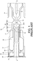
- a switching chamber 10 of a known type is shown in Figure 1 . It is a switching chamber of the "self-blast” type which is part of a gas-insulated circuit breaker.
- the switching chamber extends along a longitudinal axis XX' which globally constitutes an axis of revolution of the chamber.
- the axial and radial directions are defined with reference to the longitudinal axis XX' (the radial direction being orthogonal to the axis XX' and the axial direction being parallel to said axis).
- the switching chamber 10 comprises a pair of permanent or main contacts 12, 14 which are movable relative to one another along the axis XX'.
- contact 14 is stationary whereas contact 12 is movable along the longitudinal axis XX', under the action of an operating member (not shown).
- the switching chamber 10 also includes a pair of arcing contact 16, 18 which are also movable relative to one another along the axis XX'.
- arcing contact 16 is mechanically connected to the permanent contact 14 and is thus stationary, whereas arcing contact 16 is connected to a movable assembly 17 comprising the movable permanent contact 12.
- the switching chamber 10 is enclosed in a casing (not shown) containing an insulating gas, e.g. SF6.
- an insulating gas e.g. SF6.
- the switching chamber is operated such as to separate the permanent contacts from each other.
- the arcing contacts 16 and 18 separate shortly after that, which gives rise to an electric arc between these arcing contacts. Such arc then has to be quenched.
- the switching chamber 10 conventionally includes a main insulating nozzle 20 and an auxiliary insulating nozzle 22 which are secured to the arcing contact 18 and which contribute to delimiting an arcing region 24 where the electric arc forms when the arcing contacts 16 and 18 separate.
- a first chamber or volume referred to as the thermal volume 30 is defined inside the movable assembly 17.
- This thermal volume 30 defines a fixed volume that is brought in translation with the movable assembly 17 when the contacts separate.
- the thermal volume 30 opens out into a channel referred to as the thermal channel 32 which puts the thermal volume 30 into fluidic communication with the arcing region 24.
- Such thermal channel 32 is delimited by an outer surface 22A of the auxiliary insulating nozzle 22 and an inner surface 20A of the main insulating nozzle 20.
- the thermal channel 32 comprises a first part 32A opening in the thermal volume 30, a second part 32B opening in the arcing region 24, and a bend part 32C connecting the first part 32A to the second part 32B so as to achieve a 90 degrees turn.
- a second chamber or volume referred to as the compression volume 34 is arranged behind the thermal volume 30 and is notably delimited by a fixed back wall 36 which forms a piston or puffer which makes the volume of the compression volume 34 vary when the contacts separate.
- This back wall 36 is conventionally fitted with an over-pressure valve 37.
- the compression volume 34 communicates with the thermal volume 30 through a passageway 38 which gets closed by a valve 39 as soon as gas pressure inside the thermal volume 30 reaches a predefined level.
- the thermal energy of the arc is not sufficient to raise the gas pressure inside the thermal volume 30 at the above-mentioned predefined level, such that the valve 39 remains open. Compression of the insulating gas that will quench the arc mainly takes place in the compression volume 34 and is further increased in the thermal volume 30 by thermal energy from the arc.
- the thermal energy of the arc raises the gas pressure inside the thermal volume 30 above the predefined level, such that the valve 38 closes. Compression of the insulating gas that will quench the arc thus entirely takes place in the thermal volume 30 thanks to thermal energy from the arc.
- the bend part 32C of the thermal channel 32 is delimited by a portion of the outer surface 22A of the auxiliary insulating nozzle 22 including a first bend section B1 on the thermal volume side, a third bend section B3 on the arcing region side, and a second bend section B2 connecting the first bend section B1 to the third bend section B3.
- the first section B1 connects the second bend section B2 to a portion of the outer surface 22A delimiting the first part 32A of the thermal channel
- the third bend section B3 connects the second bend section B2 to a portion of the outer surface 22A delimiting the second part 32B of the thermal channel.
- the bend part 32C is delimited by a portion of the inner surface 20A of the main insulating nozzle 20 including a fourth bend section B4 on the thermal volume side, a sixth bend section B6 on the arcing region side, and a fifth bend section B5 connecting the fourth bend section B4 to the sixth bend section B6.
- the fourth bend section B4 connects the fifth bend section B5 to a portion of the inner surface 20A delimiting the first part 32A of the thermal channel
- the sixth bend section B6 connects the fifth bend section B5 to a portion of the inner surface 20A delimiting the second part 32B of the thermal channel.
- the first to sixth bend sections B1-B6 respectively form 30 degrees arcs of circles (see Fig. 2A : the respective angles ⁇ 1- ⁇ 6 of the first to sixth bend sections each equal 30 degrees).
- the respective radii R1, R2, R3, R4, R5 and R6 of the first to sixth bend sections B1-B6 are such that R1 > R2 > R3 and R4 > R5 > R6.
- the respective radii are decreasing from the first bend section B1 to the third bend section B3 on the one hand, and from the fourth bend section B4 to the sixth bend section B6 on the other hand.
- the respective radii R1 and R4 of the first and fourth bend sections B1 and B4 are preferably between 5 mm and 80 mm.
- the first part 32A of the thermal channel extends parallel to the axis XX' and is substantially of constant section, from the thermal volume 30 up to the bend part 32C of the thermal channel, whereas the second part 32B of the thermal channel extends orthogonal to the axis XX' and is also substantially of constant section, from the arcing region 24 up to the bend part 32C of the thermal channel.
- the radial distance D1 ( Fig. 2A ) between the outer surface 22A of the auxiliary insulating nozzle 22 and the inner surface 20A of the main insulating nozzle 20, in the first part 32A of the thermal channel, is equal to 1.35 times the radius R3 of the third bend section B3.
- the axial distance D2 between the outer surface 22A of the auxiliary insulating nozzle 22 and the inner surface 20A of the main insulating nozzle 20, in the second part 32B of the thermal channel is equal to 2.5 times the radius R3 of the third bend section B3.
- Fig. 3 shows the improvements as regards flow speed S of insulating gas in the optimized thermal channel 32 of Figs 2 and 2A (in solid line) as compared to the flow speed of insulating gas in the non-optimized thermal channel 32 of Fig 1 (in dotted line).
Landscapes
- Circuit Breakers (AREA)
Description
- The present invention relates to a switching chamber, sometimes also called a switching chamber, for a gas-insulated circuit breaker, such as a high-voltage circuit breaker, of the type comprising a thermal channel connecting an arcing region to a thermal volume provided for storing quenching gas to be injected into the arcing region.
- More precisely, the invention concerns a switching chamber comprising two arcing contacts movable relative to one another along an axis, a main insulating nozzle and an auxiliary insulating nozzle both extending around the axis such as to delimit an arcing region, a thermal volume for storing insulating gas, and a thermal channel extending between an outer surface of the auxiliary insulating nozzle and an inner surface of the main insulating nozzle so that the thermal channel connects the thermal volume to the arcing region, wherein the thermal channel comprises a first part opening in the thermal volume, a second part opening in the arcing region, and a bend part connecting the first part to the second part so as to achieve a 90 degrees turn.
- The invention also relates to a gas-insulated circuit breaker comprising such a switching chamber.
- In a single pressure switching chamber of the thermally-assisted puffer or self-blast types, the so-called thermal channel is a channel putting an arcing region into fluidic communication with a thermal volume or chamber.
- During the initial stage of current interruption, as main contacts of the switching chamber separate and an electric arc is established between the male and female arcing contacts, the thermal channel provides a conduit for feeding hot gases from the arcing region, which is the volume between the male and female arcing contacts, into the thermal volume. The arc heats the insulating gas, such as SF6, between the contacts, and the heated gas is fed into the thermal volume in order to increase the pressure in this volume. This first phase is sometimes called the thermal volume pressurization phase. In a subsequent phase, the direction of gas flow in the thermal channel reverts and the previously stored insulating gas flows from the thermal volume into the arcing region through this channel. This action promotes the flow of insulating gas that transports heat away from the arcing region and provides adequate gas density and temperature across the arcing contacts to obtain successful interruption of an AC current after it decays to zero and in order for the gap to withstand the transient recovery voltage appearing across the switching chamber.
- As is widely known, in a switching chamber of the thermally-assisted puffer type, a single volume or chamber plays the role of a compression volume, since gas inside this volume is pressurized by a moving piston or puffer, and the role of a thermal volume, since gas pressurization is increased by the arc thermal energy. In a switching chamber of the self-blast type, there are two distinct volumes or chambers, namely the thermal volume which is of fixed volume and which opens into the thermal channel, and the compression volume which is of variable volume and which is connected to the thermal volume through a valve.
- In the present disclosure, the "thermal volume" can indifferently be the single volume of a thermally-assisted puffer type switching chamber or the so-called thermal volume of a self-blast type switching chamber.
- The thermal channel is formed by the outer surface of the auxiliary nozzle and the inner surface of the main nozzle in the region between the thermal volume and the arcing region.
- The shapes currently used for the thermal channel to achieve the 90 degrees turn from the longitudinal to the radial direction with respect to the switching chamber axis are simple arc segments with constant radius throughout the turn.
- The applicant realized that such shapes are not optimal. In particular, the applicant found that these shapes lead to the formation of turbulence and eddies in the thermal channel which obstruct the insulating gas flow and reduce the efficiency of the pressurization phase of the thermal channel and of the subsequent injection of gas into the arcing region
WO-A-2013/153110 discloses a switching chamber of the prior art. - A purpose of the invention is to improve the thermal channel shape and in particular to reduce or even avoid the formation of turbulence and eddies in the thermal channel.
- To this end, an object of the present invention is a switching chamber of the aforementioned type, wherein the bend part is delimited by a portion of the outer surface of the auxiliary insulating nozzle including a first bend section on a thermal volume side, a third bend section on an arcing region side, and a second bend section connecting the first bend section to the third bend section, wherein the bend part is delimited by a portion of the inner surface of the main insulating nozzle including a fourth bend section on a thermal volume side, a sixth bend section on an arcing region side, and a fifth bend section connecting the fourth bend section to the sixth bend section, wherein in axial section view, the first to sixth bend sections form 30 degrees arcs of circles having respective radii R1, R2, R3, R4, R5 and R6, and wherein R1 > R2 > R3 and R4 > R5 > R6.
- Indeed, after intensive research, the applicant found that such shape for the thermal channel help obtaining laminar flow of the insulating gas that is first injected into the thermal volume to increase pressure and mix the gas in this volume and subsequently injected back radially into the arcing region to quench the arc.
- The invention thus permits to increase the speed of insulating gas injection. In addition, it makes it possible to reduce or even prevent the generation of turbulence and eddies inside the thermal channel that may obstruct the flow between the thermal volume and the arcing region. The efficiency of the interruption process is thus globally improved.
- According to other advantageous aspects of the invention, the switching chamber includes one or more of the following characteristics, taken alone or in any possible combination:
- the respective radii of the first to third bend sections are such that R1 = 3 x R3 and R2 = 1.8 x R3;
- the respective radii of the fourth to sixth bend sections are such that R4 = 3 x R6 and R5 = 1.8 x R6;
- the respective radii of the first to sixth bend sections are such that R1 = 3 x R3 and R2 = 1.8 x R3 and R4 = 3 x R6 and R5 = 1.8 x R6;
- the respective radii R1 and R4 of the first and fourth bend sections are between 5 mm and 80 mm;
- the first part of the thermal channel extends parallel to the axis from the thermal volume up to the bend part of the thermal channel;
- the second part of the thermal channel extends orthogonal to the axis from the arcing region up to the bend part of the thermal channel;
- the first part of the thermal channel is substantially of constant section from the thermal volume up to the bend part of the thermal channel;
- the second part of the thermal channel is substantially of constant section from the arcing region up to the bend part of the thermal channel;
- a radial distance between the outer surface of the auxiliary insulating nozzle and the inner surface of the main insulating nozzle, in the first part of the thermal channel, is equal to 1.35 times the radius R3 of the third bend section;
- an axial distance between the outer surface of the auxiliary insulating nozzle and the inner surface of the main insulating nozzle, in the second part of the thermal channel, is equal to 2.5 times the radius R3 of the third bend section.
- The invention also relates to a gas-insulated circuit breaker comprising a switching chamber of the type described above.
- The invention will be better understood and other details, advantages and characteristics of it will become clear after reading the following description given as a non-limitative example with reference to the appended drawings in which:
-
Figure 1 is a schematic fragmentary axial cross-sectional view of a known thermally-assisted self-blast type switching chamber of a circuit breaker, shown in an open position; -
Figure 2 is a schematic fragmentary axial half-cross-sectional view of a switching chamber of a circuit breaker according to a preferred embodiment of the invention; -
Figure 2A is an enlarged view of part IIA ofFigure 2 ; -
Figure 3 is a graph illustrating the flow speed S as a function of time t in a thermal channel of the switching chamber ofFig. 1 (solid line), respectively of the switching chamber ofFig. 2 (dotted line). - In all these figures, identical references may denote identical or similar elements.
- A
switching chamber 10 of a known type is shown inFigure 1 . It is a switching chamber of the "self-blast" type which is part of a gas-insulated circuit breaker. - The switching chamber extends along a longitudinal axis XX' which globally constitutes an axis of revolution of the chamber. In the present disclosure, the axial and radial directions are defined with reference to the longitudinal axis XX' (the radial direction being orthogonal to the axis XX' and the axial direction being parallel to said axis).
- The
switching chamber 10 comprises a pair of permanent ormain contacts contact 14 is stationary whereascontact 12 is movable along the longitudinal axis XX', under the action of an operating member (not shown). - The
switching chamber 10 also includes a pair of arcingcontact contact 16 is mechanically connected to thepermanent contact 14 and is thus stationary, whereas arcingcontact 16 is connected to amovable assembly 17 comprising the movablepermanent contact 12. - The
switching chamber 10 is enclosed in a casing (not shown) containing an insulating gas, e.g. SF6. - Generally speaking, when electric current flowing through the
permanent contacts arcing contacts - To that end, the
switching chamber 10 conventionally includes a maininsulating nozzle 20 and anauxiliary insulating nozzle 22 which are secured to the arcingcontact 18 and which contribute to delimiting anarcing region 24 where the electric arc forms when thearcing contacts - A first chamber or volume referred to as the
thermal volume 30 is defined inside themovable assembly 17. Thisthermal volume 30 defines a fixed volume that is brought in translation with themovable assembly 17 when the contacts separate. Thethermal volume 30 opens out into a channel referred to as thethermal channel 32 which puts thethermal volume 30 into fluidic communication with thearcing region 24. Suchthermal channel 32 is delimited by anouter surface 22A of the auxiliary insulatingnozzle 22 and aninner surface 20A of the main insulatingnozzle 20. In particular, thethermal channel 32 comprises afirst part 32A opening in thethermal volume 30, asecond part 32B opening in thearcing region 24, and abend part 32C connecting thefirst part 32A to thesecond part 32B so as to achieve a 90 degrees turn. - A second chamber or volume referred to as the
compression volume 34 is arranged behind thethermal volume 30 and is notably delimited by a fixedback wall 36 which forms a piston or puffer which makes the volume of thecompression volume 34 vary when the contacts separate. Thisback wall 36 is conventionally fitted with an over-pressurevalve 37. Thecompression volume 34 communicates with thethermal volume 30 through apassageway 38 which gets closed by avalve 39 as soon as gas pressure inside thethermal volume 30 reaches a predefined level. - When a nominal electric current is to be interrupted, the thermal energy of the arc is not sufficient to raise the gas pressure inside the
thermal volume 30 at the above-mentioned predefined level, such that thevalve 39 remains open. Compression of the insulating gas that will quench the arc mainly takes place in thecompression volume 34 and is further increased in thethermal volume 30 by thermal energy from the arc. - Now, when a higher current has to be interrupted, such as a short-circuit current, the thermal energy of the arc raises the gas pressure inside the
thermal volume 30 above the predefined level, such that thevalve 38 closes. Compression of the insulating gas that will quench the arc thus entirely takes place in thethermal volume 30 thanks to thermal energy from the arc. - The particular features of the invention will now be described with reference to
Figures 2 and 2A that show aswitching chamber 100 of the same type as the switchingchamber 10 ofFig. 1 , but wherein thethermal channel 32 has an optimized shape which makes it possible to increase the speed of insulating gas through the thermal channel and to reduce or even prevent the generation of turbulence and eddies inside the thermal channel. - As shown more clearly in
Fig. 2A , thebend part 32C of thethermal channel 32 is delimited by a portion of theouter surface 22A of the auxiliary insulatingnozzle 22 including a first bend section B1 on the thermal volume side, a third bend section B3 on the arcing region side, and a second bend section B2 connecting the first bend section B1 to the third bend section B3. In other words, the first section B1 connects the second bend section B2 to a portion of theouter surface 22A delimiting thefirst part 32A of the thermal channel, whereas the third bend section B3 connects the second bend section B2 to a portion of theouter surface 22A delimiting thesecond part 32B of the thermal channel. - Similarly, the
bend part 32C is delimited by a portion of theinner surface 20A of the main insulatingnozzle 20 including a fourth bend section B4 on the thermal volume side, a sixth bend section B6 on the arcing region side, and a fifth bend section B5 connecting the fourth bend section B4 to the sixth bend section B6. In other words, the fourth bend section B4 connects the fifth bend section B5 to a portion of theinner surface 20A delimiting thefirst part 32A of the thermal channel, whereas the sixth bend section B6 connects the fifth bend section B5 to a portion of theinner surface 20A delimiting thesecond part 32B of the thermal channel. - Moreover, in axial section view as in
Figures 2 and 2A , the first to sixth bend sections B1-B6 respectively form 30 degrees arcs of circles (seeFig. 2A : the respective angles θ1-θ6 of the first to sixth bend sections each equal 30 degrees). - In addition, the respective radii R1, R2, R3, R4, R5 and R6 of the first to sixth bend sections B1-B6 are such that R1 > R2 > R3 and R4 > R5 > R6. In other words, the respective radii are decreasing from the first bend section B1 to the third bend section B3 on the one hand, and from the fourth bend section B4 to the sixth bend section B6 on the other hand.
- In the preferred embodiment, the respective radii R1, R2, R3, R4, R5 and R6 of the first to sixth bend sections B1-B6 are such that:


- Moreover, the respective radii R1 and R4 of the first and fourth bend sections B1 and B4 are preferably between 5 mm and 80 mm.
- In the illustrated embodiment, the
first part 32A of the thermal channel extends parallel to the axis XX' and is substantially of constant section, from thethermal volume 30 up to thebend part 32C of the thermal channel, whereas thesecond part 32B of the thermal channel extends orthogonal to the axis XX' and is also substantially of constant section, from the arcingregion 24 up to thebend part 32C of the thermal channel. - In the illustrated example, the radial distance D1 (
Fig. 2A ) between theouter surface 22A of the auxiliary insulatingnozzle 22 and theinner surface 20A of the main insulatingnozzle 20, in thefirst part 32A of the thermal channel, is equal to 1.35 times the radius R3 of the third bend section B3. In addition, the axial distance D2 between theouter surface 22A of the auxiliary insulatingnozzle 22 and theinner surface 20A of the main insulatingnozzle 20, in thesecond part 32B of the thermal channel, is equal to 2.5 times the radius R3 of the third bend section B3. -
Fig. 3 shows the improvements as regards flow speed S of insulating gas in the optimizedthermal channel 32 ofFigs 2 and 2A (in solid line) as compared to the flow speed of insulating gas in the non-optimizedthermal channel 32 ofFig 1 (in dotted line). - This written description uses examples to disclose the invention, including the preferred embodiments, and also to enable any person skilled in the art to practice the invention, including making and using any devices or systems and performing any incorporated methods. The patentable scope of the invention is defined by the claims.
Claims (12)
- A switching chamber (10) for a gas-insulated circuit breaker, comprising:two arcing contacts (12,14) movable relative to one another along an axis (XX1),a main insulating nozzle (20) and an auxiliary insulating nozzle (22) both extending around the axis (XX1) such as to delimit an arcing region (24),a thermal volume (30) for storing insulating gas,a thermal channel (32) extending between an outer surface (22A) of the auxiliary insulating nozzle (22) and an inner surface (20A) of the main insulating nozzle (20) so that the thermal channel (32) connects the thermal volume (30) to the arcing region (24),wherein the thermal channel (32) comprises a first part (32A) opening in the thermal volume (30), a second part opening (32B) in the arcing region (24), and a bend part (32C) connecting the first part (32A) to the second part (32B) so as to achieve a 90 degrees turn,wherein the bend part (32C) is delimited by a portion of the outer surface (22A) of the auxiliary insulating nozzle (22) including a first bend section (B1) on a thermal volume side, a third bend section (B3) on an arcing region side, and a second bend section (B2) connecting the first bend section (B1) to the third bend section (B3),characterised in thatthe bend part (32C) is delimited by a portion of the inner surface (20A) of the main insulating nozzle (20) including a fourth bend section (B4) on a thermal volume side, a sixth bend section (B6) on an arcing region side, and a fifth bend section (B5) connecting the fourth bend section (B4) to the sixth bend section (B6),wherein in axial section view, the first to sixth bend sections (B1-B6) form 30 degrees arcs of circles having respective radii R1, R2, R3, R4, R5 and R6,wherein R1 > R2 > R3 and R4 > R5 > R6.
- The switching chamber according to claim 1, wherein the respective radii of the first to third bend sections (B1-B3) are such that R1 = 3 x R3
and R2 = 1.8 x R3. - The switching chamber according to claim 1 or 2, wherein the respective radii of the fourth to sixth bend sections (B4-B6) are such that R4 = 3 x R6
and R5 = 1.8 x R6. - The switching chamber according to any of claims 1 to 3, wherein the respective radii of the first to sixth bend sections (B1-B6) are such that


- The switching chamber according to any preceding claim, wherein the respective radii R1 and R4 of the first (B1) and fourth (B4) bend sections are between 5 mm and 80 mm.
- The switching chamber according to any preceding claim, wherein the first part (32A) of the thermal channel (32) extends parallel to the axis (XX1) from the thermal volume (30) up to the bend part (32C) of the thermal channel (32).
- The switching chamber according to any preceding claim, wherein the second part (32B) of the thermal channel (32) extends orthogonal to the axis (XX1) from the arcing region (24) up to the bend part (32C) of the thermal channel (32).
- The switching chamber according to any preceding claim, wherein the first part (32A) of the thermal channel (32) is substantially of constant section from the thermal volume (30) up to the bend part (32C) of the thermal channel (32).
- The switching chamber according to any preceding claim, wherein the second part (32B) of the thermal channel (32) is substantially of constant section from the arcing region (24) up to the bend part (32C) of the thermal channel (32).
- The switching chamber according to any preceding claim, wherein a radial distance between the outer surface (22A) of the auxiliary insulating nozzle (22) and the inner surface (20A) of the main insulating nozzle (20), in the first part (32A) of the thermal channel (32), is equal to 1.35 times the radius R3 of the third bend section (B3).
- The switching chamber according to any preceding claim, wherein an axial distance between the outer surface (22A) of the auxiliary insulating nozzle (22) and the inner surface (20A) of the main insulating nozzle (20), in the second part (32B) of the thermal channel (32), is equal to 2.5 times the radius R3 of the third bend section (B3).
- A gas-insulated circuit breaker comprising a switching chamber (10) according to any of claims 1 to 11.
Applications Claiming Priority (2)
| Application Number | Priority Date | Filing Date | Title |
|---|---|---|---|
| US15/475,424 US10026571B1 (en) | 2017-03-31 | 2017-03-31 | Switching chamber for a gas-insulated circuit breaker comprising an optimized thermal channel |
| PCT/EP2018/057063 WO2018177824A1 (en) | 2017-03-31 | 2018-03-20 | A switching chamber for a gas-insulated circuit breaker comprising an optimized thermal channel |
Publications (2)
| Publication Number | Publication Date |
|---|---|
| EP3586349A1 EP3586349A1 (en) | 2020-01-01 |
| EP3586349B1 true EP3586349B1 (en) | 2021-05-19 |
Family
ID=61750135
Family Applications (1)
| Application Number | Title | Priority Date | Filing Date |
|---|---|---|---|
| EP18712592.7A Active EP3586349B1 (en) | 2017-03-31 | 2018-03-20 | A switching chamber for a gas-insulated circuit breaker comprising an optimized thermal channel |
Country Status (3)
| Country | Link |
|---|---|
| US (1) | US10026571B1 (en) |
| EP (1) | EP3586349B1 (en) |
| WO (1) | WO2018177824A1 (en) |
Families Citing this family (2)
| Publication number | Priority date | Publication date | Assignee | Title |
|---|---|---|---|---|
| EP3407370B1 (en) * | 2017-05-24 | 2020-04-01 | General Electric Technology GmbH | A gas blast switch comprising an optimized gas storage chamber |
| EP4246548A1 (en) * | 2022-03-15 | 2023-09-20 | Hitachi Energy Switzerland AG | Interrupter unit for gas-insulated high or medium voltage device and gas-insulated high or medium voltage device |
Family Cites Families (13)
| Publication number | Priority date | Publication date | Assignee | Title |
|---|---|---|---|---|
| JPS5438572A (en) * | 1977-09-02 | 1979-03-23 | Hitachi Ltd | Buffer type gas circuit breaker |
| CH643394A5 (en) * | 1978-10-26 | 1984-05-30 | Tokyo Shibaura Electric Co | Throttle switch. |
| FR2596575B1 (en) * | 1986-03-26 | 1988-05-20 | Alsthom | DIELECTRIC GAS CIRCUIT BREAKER UNDER PRESSURE |
| FR2638564B1 (en) * | 1988-11-02 | 1990-11-30 | Alsthom Gec | HIGH VOLTAGE CIRCUIT BREAKER WITH DIELECTRIC GAS UNDER PRESSURE |
| FR2647255B1 (en) * | 1989-05-17 | 1993-04-23 | Alsthom Gec | HIGH VOLTAGE CIRCUIT BREAKER WITH BLOWING DIELECTRIC GAS |
| FR2647949B1 (en) * | 1989-05-31 | 1994-02-18 | Gec Alsthom Sa | HIGH VOLTAGE CIRCUIT BREAKER WITH SUPPLY DIELECTRIC GAS |
| FR2661550B1 (en) * | 1990-04-26 | 1992-06-12 | Alsthom Gec | HIGH VOLTAGE CIRCUIT BREAKER WITH SERIES ARC. |
| FR2808118B1 (en) * | 2000-04-19 | 2004-06-18 | Alstom | SELF-BLOWING SWITCH WITH A TWO-VOLUME CUT-OFF CHAMBER |
| EP1675144A1 (en) * | 2004-12-23 | 2006-06-28 | ABB Technology AG | High voltage switch with arc resistant short circuit current conductor |
| FR2937179A1 (en) * | 2008-10-09 | 2010-04-16 | Areva T & D Sa | BREAKER CHAMBER FOR HIGH VOLTAGE CIRCUIT BREAKER WITH IMPROVED ARC BLOW |
| JP5516568B2 (en) * | 2011-12-28 | 2014-06-11 | 株式会社日立製作所 | Puffer type gas circuit breaker |
| WO2013153112A1 (en) * | 2012-04-11 | 2013-10-17 | Abb Technology Ag | Circuit breaker |
| EP2887367A1 (en) * | 2013-12-19 | 2015-06-24 | ABB Technology AB | Gas-insulated high-voltage circuit breaker |
-
2017
- 2017-03-31 US US15/475,424 patent/US10026571B1/en active Active
-
2018
- 2018-03-20 EP EP18712592.7A patent/EP3586349B1/en active Active
- 2018-03-20 WO PCT/EP2018/057063 patent/WO2018177824A1/en not_active Ceased
Non-Patent Citations (1)
| Title |
|---|
| None * |
Also Published As
| Publication number | Publication date |
|---|---|
| EP3586349A1 (en) | 2020-01-01 |
| WO2018177824A1 (en) | 2018-10-04 |
| US10026571B1 (en) | 2018-07-17 |
Similar Documents
| Publication | Publication Date | Title |
|---|---|---|
| JP5516568B2 (en) | Puffer type gas circuit breaker | |
| US9741514B2 (en) | Switching arrangement | |
| JPWO2015008515A1 (en) | Gas circuit breaker | |
| KR20150003396A (en) | Gas circuit breaker | |
| US7732727B2 (en) | Heavy-duty circuit-breaker with sealing against hot gas | |
| US10026571B1 (en) | Switching chamber for a gas-insulated circuit breaker comprising an optimized thermal channel | |
| US3842226A (en) | Circuit interrupter using a double-throat nozzle | |
| US10347446B2 (en) | Gas blast switch comprising an optimized gas storage chamber | |
| KR101701817B1 (en) | Gas isolated circuit breaker | |
| JP2013125720A (en) | Puffer type gas circuit breaker | |
| US11373824B2 (en) | Gas-insulated high or medium voltage circuit breaker | |
| JPH02230625A (en) | High voltage and medium voltage gas circuit breaker | |
| EP3503152B1 (en) | Gas-insulated high or medium voltage circuit breaker | |
| CN106128887B (en) | Low-voltage vacuum circuit breaker and vacuum arc-extinguishing chamber for circuit breaker | |
| EP3985703A1 (en) | Circuit breaker comprising an improved gas flow management | |
| US20120261385A1 (en) | Gas circuit breaker | |
| CN104969324A (en) | Contact arrangement and electrical switching device with such contact arrangement | |
| US20100096363A1 (en) | Switching chamber for a high-voltage breaker, and a high-voltage breaker | |
| EP4141901B1 (en) | Metal enclosed circuit breaker | |
| EP3872829B1 (en) | Gas circuit breaker | |
| EP3433869B1 (en) | Electrical circuit breaker device | |
| US12322935B2 (en) | Compressed gas switch | |
| JP2016143473A (en) | Gas circuit breaker | |
| EP3355332B1 (en) | Circuit breaker comprising a double wall surrounding its thermal chamber | |
| JP5422472B2 (en) | Gas circuit breaker |
Legal Events
| Date | Code | Title | Description |
|---|---|---|---|
| STAA | Information on the status of an ep patent application or granted ep patent |
Free format text: STATUS: UNKNOWN |
|
| STAA | Information on the status of an ep patent application or granted ep patent |
Free format text: STATUS: THE INTERNATIONAL PUBLICATION HAS BEEN MADE |
|
| PUAI | Public reference made under article 153(3) epc to a published international application that has entered the european phase |
Free format text: ORIGINAL CODE: 0009012 |
|
| STAA | Information on the status of an ep patent application or granted ep patent |
Free format text: STATUS: REQUEST FOR EXAMINATION WAS MADE |
|
| 17P | Request for examination filed |
Effective date: 20190924 |
|
| AK | Designated contracting states |
Kind code of ref document: A1 Designated state(s): AL AT BE BG CH CY CZ DE DK EE ES FI FR GB GR HR HU IE IS IT LI LT LU LV MC MK MT NL NO PL PT RO RS SE SI SK SM TR |
|
| AX | Request for extension of the european patent |
Extension state: BA ME |
|
| DAV | Request for validation of the european patent (deleted) | ||
| DAX | Request for extension of the european patent (deleted) | ||
| GRAP | Despatch of communication of intention to grant a patent |
Free format text: ORIGINAL CODE: EPIDOSNIGR1 |
|
| STAA | Information on the status of an ep patent application or granted ep patent |
Free format text: STATUS: GRANT OF PATENT IS INTENDED |
|
| INTG | Intention to grant announced |
Effective date: 20201211 |
|
| GRAS | Grant fee paid |
Free format text: ORIGINAL CODE: EPIDOSNIGR3 |
|
| GRAA | (expected) grant |
Free format text: ORIGINAL CODE: 0009210 |
|
| STAA | Information on the status of an ep patent application or granted ep patent |
Free format text: STATUS: THE PATENT HAS BEEN GRANTED |
|
| AK | Designated contracting states |
Kind code of ref document: B1 Designated state(s): AL AT BE BG CH CY CZ DE DK EE ES FI FR GB GR HR HU IE IS IT LI LT LU LV MC MK MT NL NO PL PT RO RS SE SI SK SM TR |
|
| REG | Reference to a national code |
Ref country code: GB Ref legal event code: FG4D |
|
| REG | Reference to a national code |
Ref country code: CH Ref legal event code: EP |
|
| REG | Reference to a national code |
Ref country code: DE Ref legal event code: R096 Ref document number: 602018017294 Country of ref document: DE |
|
| REG | Reference to a national code |
Ref country code: AT Ref legal event code: REF Ref document number: 1394798 Country of ref document: AT Kind code of ref document: T Effective date: 20210615 |
|
| REG | Reference to a national code |
Ref country code: IE Ref legal event code: FG4D |
|
| REG | Reference to a national code |
Ref country code: LT Ref legal event code: MG9D |
|
| REG | Reference to a national code |
Ref country code: AT Ref legal event code: MK05 Ref document number: 1394798 Country of ref document: AT Kind code of ref document: T Effective date: 20210519 |
|
| REG | Reference to a national code |
Ref country code: NL Ref legal event code: MP Effective date: 20210519 |
|
| PG25 | Lapsed in a contracting state [announced via postgrant information from national office to epo] |
Ref country code: AT Free format text: LAPSE BECAUSE OF FAILURE TO SUBMIT A TRANSLATION OF THE DESCRIPTION OR TO PAY THE FEE WITHIN THE PRESCRIBED TIME-LIMIT Effective date: 20210519 Ref country code: BG Free format text: LAPSE BECAUSE OF FAILURE TO SUBMIT A TRANSLATION OF THE DESCRIPTION OR TO PAY THE FEE WITHIN THE PRESCRIBED TIME-LIMIT Effective date: 20210819 Ref country code: HR Free format text: LAPSE BECAUSE OF FAILURE TO SUBMIT A TRANSLATION OF THE DESCRIPTION OR TO PAY THE FEE WITHIN THE PRESCRIBED TIME-LIMIT Effective date: 20210519 Ref country code: LT Free format text: LAPSE BECAUSE OF FAILURE TO SUBMIT A TRANSLATION OF THE DESCRIPTION OR TO PAY THE FEE WITHIN THE PRESCRIBED TIME-LIMIT Effective date: 20210519 Ref country code: FI Free format text: LAPSE BECAUSE OF FAILURE TO SUBMIT A TRANSLATION OF THE DESCRIPTION OR TO PAY THE FEE WITHIN THE PRESCRIBED TIME-LIMIT Effective date: 20210519 |
|
| PG25 | Lapsed in a contracting state [announced via postgrant information from national office to epo] |
Ref country code: PT Free format text: LAPSE BECAUSE OF FAILURE TO SUBMIT A TRANSLATION OF THE DESCRIPTION OR TO PAY THE FEE WITHIN THE PRESCRIBED TIME-LIMIT Effective date: 20210920 Ref country code: RS Free format text: LAPSE BECAUSE OF FAILURE TO SUBMIT A TRANSLATION OF THE DESCRIPTION OR TO PAY THE FEE WITHIN THE PRESCRIBED TIME-LIMIT Effective date: 20210519 Ref country code: SE Free format text: LAPSE BECAUSE OF FAILURE TO SUBMIT A TRANSLATION OF THE DESCRIPTION OR TO PAY THE FEE WITHIN THE PRESCRIBED TIME-LIMIT Effective date: 20210519 Ref country code: NO Free format text: LAPSE BECAUSE OF FAILURE TO SUBMIT A TRANSLATION OF THE DESCRIPTION OR TO PAY THE FEE WITHIN THE PRESCRIBED TIME-LIMIT Effective date: 20210819 Ref country code: PL Free format text: LAPSE BECAUSE OF FAILURE TO SUBMIT A TRANSLATION OF THE DESCRIPTION OR TO PAY THE FEE WITHIN THE PRESCRIBED TIME-LIMIT Effective date: 20210519 Ref country code: LV Free format text: LAPSE BECAUSE OF FAILURE TO SUBMIT A TRANSLATION OF THE DESCRIPTION OR TO PAY THE FEE WITHIN THE PRESCRIBED TIME-LIMIT Effective date: 20210519 Ref country code: IS Free format text: LAPSE BECAUSE OF FAILURE TO SUBMIT A TRANSLATION OF THE DESCRIPTION OR TO PAY THE FEE WITHIN THE PRESCRIBED TIME-LIMIT Effective date: 20210919 Ref country code: GR Free format text: LAPSE BECAUSE OF FAILURE TO SUBMIT A TRANSLATION OF THE DESCRIPTION OR TO PAY THE FEE WITHIN THE PRESCRIBED TIME-LIMIT Effective date: 20210820 |
|
| PG25 | Lapsed in a contracting state [announced via postgrant information from national office to epo] |
Ref country code: NL Free format text: LAPSE BECAUSE OF FAILURE TO SUBMIT A TRANSLATION OF THE DESCRIPTION OR TO PAY THE FEE WITHIN THE PRESCRIBED TIME-LIMIT Effective date: 20210519 |
|
| PG25 | Lapsed in a contracting state [announced via postgrant information from national office to epo] |
Ref country code: CZ Free format text: LAPSE BECAUSE OF FAILURE TO SUBMIT A TRANSLATION OF THE DESCRIPTION OR TO PAY THE FEE WITHIN THE PRESCRIBED TIME-LIMIT Effective date: 20210519 Ref country code: DK Free format text: LAPSE BECAUSE OF FAILURE TO SUBMIT A TRANSLATION OF THE DESCRIPTION OR TO PAY THE FEE WITHIN THE PRESCRIBED TIME-LIMIT Effective date: 20210519 Ref country code: RO Free format text: LAPSE BECAUSE OF FAILURE TO SUBMIT A TRANSLATION OF THE DESCRIPTION OR TO PAY THE FEE WITHIN THE PRESCRIBED TIME-LIMIT Effective date: 20210519 Ref country code: ES Free format text: LAPSE BECAUSE OF FAILURE TO SUBMIT A TRANSLATION OF THE DESCRIPTION OR TO PAY THE FEE WITHIN THE PRESCRIBED TIME-LIMIT Effective date: 20210519 Ref country code: EE Free format text: LAPSE BECAUSE OF FAILURE TO SUBMIT A TRANSLATION OF THE DESCRIPTION OR TO PAY THE FEE WITHIN THE PRESCRIBED TIME-LIMIT Effective date: 20210519 Ref country code: SK Free format text: LAPSE BECAUSE OF FAILURE TO SUBMIT A TRANSLATION OF THE DESCRIPTION OR TO PAY THE FEE WITHIN THE PRESCRIBED TIME-LIMIT Effective date: 20210519 Ref country code: SM Free format text: LAPSE BECAUSE OF FAILURE TO SUBMIT A TRANSLATION OF THE DESCRIPTION OR TO PAY THE FEE WITHIN THE PRESCRIBED TIME-LIMIT Effective date: 20210519 |
|
| REG | Reference to a national code |
Ref country code: DE Ref legal event code: R097 Ref document number: 602018017294 Country of ref document: DE |
|
| PLBE | No opposition filed within time limit |
Free format text: ORIGINAL CODE: 0009261 |
|
| STAA | Information on the status of an ep patent application or granted ep patent |
Free format text: STATUS: NO OPPOSITION FILED WITHIN TIME LIMIT |
|
| 26N | No opposition filed |
Effective date: 20220222 |
|
| PG25 | Lapsed in a contracting state [announced via postgrant information from national office to epo] |
Ref country code: IS Free format text: LAPSE BECAUSE OF FAILURE TO SUBMIT A TRANSLATION OF THE DESCRIPTION OR TO PAY THE FEE WITHIN THE PRESCRIBED TIME-LIMIT Effective date: 20210919 Ref country code: AL Free format text: LAPSE BECAUSE OF FAILURE TO SUBMIT A TRANSLATION OF THE DESCRIPTION OR TO PAY THE FEE WITHIN THE PRESCRIBED TIME-LIMIT Effective date: 20210519 |
|
| PG25 | Lapsed in a contracting state [announced via postgrant information from national office to epo] |
Ref country code: IT Free format text: LAPSE BECAUSE OF FAILURE TO SUBMIT A TRANSLATION OF THE DESCRIPTION OR TO PAY THE FEE WITHIN THE PRESCRIBED TIME-LIMIT Effective date: 20210519 |
|
| PG25 | Lapsed in a contracting state [announced via postgrant information from national office to epo] |
Ref country code: MC Free format text: LAPSE BECAUSE OF FAILURE TO SUBMIT A TRANSLATION OF THE DESCRIPTION OR TO PAY THE FEE WITHIN THE PRESCRIBED TIME-LIMIT Effective date: 20210519 |
|
| GBPC | Gb: european patent ceased through non-payment of renewal fee |
Effective date: 20220320 |
|
| REG | Reference to a national code |
Ref country code: BE Ref legal event code: MM Effective date: 20220331 |
|
| PG25 | Lapsed in a contracting state [announced via postgrant information from national office to epo] |
Ref country code: LU Free format text: LAPSE BECAUSE OF NON-PAYMENT OF DUE FEES Effective date: 20220320 Ref country code: IE Free format text: LAPSE BECAUSE OF NON-PAYMENT OF DUE FEES Effective date: 20220320 Ref country code: GB Free format text: LAPSE BECAUSE OF NON-PAYMENT OF DUE FEES Effective date: 20220320 |
|
| PG25 | Lapsed in a contracting state [announced via postgrant information from national office to epo] |
Ref country code: BE Free format text: LAPSE BECAUSE OF NON-PAYMENT OF DUE FEES Effective date: 20220331 |
|
| P01 | Opt-out of the competence of the unified patent court (upc) registered |
Effective date: 20230522 |
|
| PG25 | Lapsed in a contracting state [announced via postgrant information from national office to epo] |
Ref country code: MK Free format text: LAPSE BECAUSE OF FAILURE TO SUBMIT A TRANSLATION OF THE DESCRIPTION OR TO PAY THE FEE WITHIN THE PRESCRIBED TIME-LIMIT Effective date: 20210519 Ref country code: CY Free format text: LAPSE BECAUSE OF FAILURE TO SUBMIT A TRANSLATION OF THE DESCRIPTION OR TO PAY THE FEE WITHIN THE PRESCRIBED TIME-LIMIT Effective date: 20210519 |
|
| PG25 | Lapsed in a contracting state [announced via postgrant information from national office to epo] |
Ref country code: HU Free format text: LAPSE BECAUSE OF FAILURE TO SUBMIT A TRANSLATION OF THE DESCRIPTION OR TO PAY THE FEE WITHIN THE PRESCRIBED TIME-LIMIT; INVALID AB INITIO Effective date: 20180320 |
|
| PG25 | Lapsed in a contracting state [announced via postgrant information from national office to epo] |
Ref country code: MT Free format text: LAPSE BECAUSE OF FAILURE TO SUBMIT A TRANSLATION OF THE DESCRIPTION OR TO PAY THE FEE WITHIN THE PRESCRIBED TIME-LIMIT Effective date: 20210519 |
|
| PGFP | Annual fee paid to national office [announced via postgrant information from national office to epo] |
Ref country code: CH Payment date: 20250401 Year of fee payment: 8 |
|
| PG25 | Lapsed in a contracting state [announced via postgrant information from national office to epo] |
Ref country code: TR Free format text: LAPSE BECAUSE OF FAILURE TO SUBMIT A TRANSLATION OF THE DESCRIPTION OR TO PAY THE FEE WITHIN THE PRESCRIBED TIME-LIMIT Effective date: 20210519 |
|
| REG | Reference to a national code |
Ref country code: CH Ref legal event code: U11 Free format text: ST27 STATUS EVENT CODE: U-0-0-U10-U11 (AS PROVIDED BY THE NATIONAL OFFICE) Effective date: 20260401 |
|
| PGFP | Annual fee paid to national office [announced via postgrant information from national office to epo] |
Ref country code: DE Payment date: 20260219 Year of fee payment: 9 |
|
| PGFP | Annual fee paid to national office [announced via postgrant information from national office to epo] |
Ref country code: FR Payment date: 20260219 Year of fee payment: 9 |