EP3586068B1 - Air vent and method for mounting said air vent - Google Patents
Air vent and method for mounting said air vent Download PDFInfo
- Publication number
- EP3586068B1 EP3586068B1 EP18710347.8A EP18710347A EP3586068B1 EP 3586068 B1 EP3586068 B1 EP 3586068B1 EP 18710347 A EP18710347 A EP 18710347A EP 3586068 B1 EP3586068 B1 EP 3586068B1
- Authority
- EP
- European Patent Office
- Prior art keywords
- vent
- blade
- elements
- blades
- drain
- Prior art date
- Legal status (The legal status is an assumption and is not a legal conclusion. Google has not performed a legal analysis and makes no representation as to the accuracy of the status listed.)
- Active
Links
- 238000000034 method Methods 0.000 title claims description 12
- XLYOFNOQVPJJNP-UHFFFAOYSA-N water Substances O XLYOFNOQVPJJNP-UHFFFAOYSA-N 0.000 claims description 45
- 230000000694 effects Effects 0.000 description 5
- 239000003595 mist Substances 0.000 description 4
- 230000005484 gravity Effects 0.000 description 2
- 239000000463 material Substances 0.000 description 2
- 238000001556 precipitation Methods 0.000 description 2
- 230000005534 acoustic noise Effects 0.000 description 1
- 238000010276 construction Methods 0.000 description 1
- 230000001627 detrimental effect Effects 0.000 description 1
- 230000002401 inhibitory effect Effects 0.000 description 1
- 238000009434 installation Methods 0.000 description 1
- 230000003993 interaction Effects 0.000 description 1
- 238000004519 manufacturing process Methods 0.000 description 1
- 238000003466 welding Methods 0.000 description 1
Images


Classifications
-
- F—MECHANICAL ENGINEERING; LIGHTING; HEATING; WEAPONS; BLASTING
- F24—HEATING; RANGES; VENTILATING
- F24F—AIR-CONDITIONING; AIR-HUMIDIFICATION; VENTILATION; USE OF AIR CURRENTS FOR SCREENING
- F24F7/00—Ventilation
-
- E—FIXED CONSTRUCTIONS
- E06—DOORS, WINDOWS, SHUTTERS, OR ROLLER BLINDS IN GENERAL; LADDERS
- E06B—FIXED OR MOVABLE CLOSURES FOR OPENINGS IN BUILDINGS, VEHICLES, FENCES OR LIKE ENCLOSURES IN GENERAL, e.g. DOORS, WINDOWS, BLINDS, GATES
- E06B7/00—Special arrangements or measures in connection with doors or windows
- E06B7/02—Special arrangements or measures in connection with doors or windows for providing ventilation, e.g. through double windows; Arrangement of ventilation roses
- E06B7/08—Louvre doors, windows or grilles
- E06B7/082—Louvre doors, windows or grilles with rigid or slidable lamellae
-
- F—MECHANICAL ENGINEERING; LIGHTING; HEATING; WEAPONS; BLASTING
- F24—HEATING; RANGES; VENTILATING
- F24F—AIR-CONDITIONING; AIR-HUMIDIFICATION; VENTILATION; USE OF AIR CURRENTS FOR SCREENING
- F24F13/00—Details common to, or for air-conditioning, air-humidification, ventilation or use of air currents for screening
- F24F13/08—Air-flow control members, e.g. louvres, grilles, flaps or guide plates
- F24F13/082—Grilles, registers or guards
- F24F13/084—Grilles, registers or guards with mounting arrangements, e.g. snap fasteners for mounting to the wall or duct
-
- F—MECHANICAL ENGINEERING; LIGHTING; HEATING; WEAPONS; BLASTING
- F24—HEATING; RANGES; VENTILATING
- F24F—AIR-CONDITIONING; AIR-HUMIDIFICATION; VENTILATION; USE OF AIR CURRENTS FOR SCREENING
- F24F7/00—Ventilation
- F24F7/04—Ventilation with ducting systems, e.g. by double walls; with natural circulation
-
- F—MECHANICAL ENGINEERING; LIGHTING; HEATING; WEAPONS; BLASTING
- F24—HEATING; RANGES; VENTILATING
- F24F—AIR-CONDITIONING; AIR-HUMIDIFICATION; VENTILATION; USE OF AIR CURRENTS FOR SCREENING
- F24F7/00—Ventilation
- F24F2007/0025—Ventilation using vent ports in a wall
-
- F—MECHANICAL ENGINEERING; LIGHTING; HEATING; WEAPONS; BLASTING
- F24—HEATING; RANGES; VENTILATING
- F24F—AIR-CONDITIONING; AIR-HUMIDIFICATION; VENTILATION; USE OF AIR CURRENTS FOR SCREENING
- F24F2221/00—Details or features not otherwise provided for
- F24F2221/52—Weather protecting means, e.g. against wind, rain or snow
Definitions
- the present invention relates to air vents.
- it relates to a vent, a method for mounting a vent, and a vent kit.
- Passive air vents are a common way to replace stale air with fresh air.
- Many state-of-the-art air vents are able to provide a high flow with relatively low noise while providing cover against for instance rain and birds, but have disadvantages.
- louvre-type vents are simple and provide some protection against rain, but they tend to be noisy, and they not particularly rainproof by any standard.
- Patent publication CA 2,405,534 discloses a roof vent that comprises two parts, a cover and a conduit.
- the conduit, with a pipeline already attached, is said to be easily connected to the cover, after the cover has been installed on a roof.
- the conduit will plug into the cover making installation "easy”.
- the vent includes a channel or moat which surrounds the outlet of the conduit.
- Patent publication US 2012/015596 relates to two devices that are used to let fresh air in or through a window or opening but at the same time keep rain or any other kind of precipitation out. It is stated that it is a device that will enable people to keep a window or an opening open even in inclement weather or when precipitation of any kind threatens to enter the opening or window.
- Patent publication GB 613,720 relates to ventilating openings, and in particular to louvres arranged with gutters for carrying rain.
- Document FR 2 529 929 A1 discloses a vent comprising: a support frame having an inner perimeter, a set of blades arranged in an array, the first end of each blade is attached to a corresponding first part of the frame, and the second end of each blade is attached to a corresponding second part of the frame, a first substantially flat portion forms an initial part of a cross-section of each blade, and the first substantially flat portion is followed by a ridge or valley portion.
- the invention provides a vent according to claim 1.
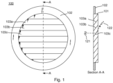
- a well-known vent not part of the invention illustrated schematically in Fig. 1 comprises blades 103a, 103b, 103c attached to a frame 101.
- the vent also has a cover flange 102 for fitting the vent against a surface, such as a wall.
- the blades are flat and arranged at an angle. This provides some protection against rain, which is illustrated as element 121, but there is a significant amount of splashing when rain hits the blades, causing drops to get through the vent, as illustrated by drops 122.
- the angling of the blades causes air to be redirected, resulting in an uneven pressure profile across the vent going from the top of the vent to the bottom of the vent in Fig. 1 .
- Fig. 8 illustrates a cross-section of a vent not part of the invention similar to the one in Fig. 1 , although the vent 800 in Fig. 8 has blades that allow more rain to enter through the vent. Blades 803a, 803b, and 803c are separated so much that rain can pass between the blades relatively easily, especially in the presence of gusts.
- FIG. 5a , 5c and 5d Examples of cross-sections in accordance with the present invention are shown in Figs. 5a , 5c and 5d and will be discussed later in the specification.
- the present invention differs from these known vents at least by comprising blades that are not flat, but have a flat portion followed by a ridge or valley portion. Vents in accordance with the present invention create significantly less noise, they may provide a significantly lower pressure drop, and they provide much better rain protection compared to the vents in Figs. 1 and 8 .
- Patent publication CA 2,405,534 illustrates entirely flat blades and is therefore not remotely capable of providing the crucial effects provided by the present invention, for instance that of leading water to the perimeter for draining along the perimeter and at least partly inhibiting water from entering through the vent.
- gutters are a crucial feature.
- the present invention has flat portions forming initial parts of the cross-sections.
- US 2012/015596 also does not describe the blade shapes of the present invention.
- blades are either substantially the same as known simple louvres, or they are not adapted to allow rain to drain onto an inner perimeter and drain along the inner perimeter, or the blades are not fixed on the inner perimenter of a frame in each end, and each blade is essentially a gutter, and water runs from gutter to gutter, zigzagging down near the middle of the vent seen from a front side.
- Fig. 7 illustrates another known vent 700 which is not part of the invention, specifically designed to prevent rain from entering.
- Blades 703a, 703b, 703c are arranged in an array.
- the blades are configured with various appendages 751, 752, 753 for catching rain and mist. Due to appendages 751 and 753, the blades at the entry and exit of the vent experience vortices.
- the specific design also results in a significant pressure drop across the vent, which is not desirable.
- the large angle of the blades relative to causes air 741, 742 to be redirected, contributing to the significant pressure drop.
- Embodiments of the present invention differ from the vent in Fig. 7 at least in that the initial portion of the blades are substantially flat, i.e. without crooked appendages.
- Figs. 1 , 7 and 8 Not visible in Figs. 1 , 7 and 8 is the lack of an opening between the blades and the respective frames, which prevents water to drain to and along the inner perimeter.
- a larger distance allows a larger flow of water to drain from the blades onto the inner perimeters. However, if the distance is too large, rain will be able to travel along the inner perimeter, through the vent, at higher wind speeds.
- the ridge or valley portion helps capture rain.
- a ridge is preferred, as this provides a surprisingly effective protection against rain.
- the flatness of the initial part of the cross-section prevents creation of vortices, as opposed to the vent illustrated in Fig. 7 . More importantly, however, the first substantially flat portion allows rain to run along the blade, towards the inner perimeter, and through the openings as described above.
- the first substantially flat portion of two adjacent blades are substantially parallel (such as parallel). This provides a smoother air flow through the vent.
- the cross-section is preferably taken as an intersection between said each blade and a plane which is perpendicular to a line extending from the first end of said each blade to the second end of said each blade.
- Figs. 5a , 5c, 5d , 10D(a) , 11D(a) and 12D(a) illustrate such cross-sections.
- the ridge or valley portion of the cross-section is followed by a second substantially flat portion forming a final part of the cross-section.
- a second substantially flat portion can be used to direct the air as desired, but more importantly, it can also assist in the draining away of water, just like the first substantially flat portion forming the initial part of the blade.
- the second substantially flat portion of two adjacent blades are substantially parallel.
- the vent frame can have arbitrary shapes, such as circular or rectangular. This is a matter of design and could be determined by the specific hole in which the vent is should fit.
- the first substantially flat portions of two adjacent blades in the vent form an inlet having an inlet direction that is substantially parallel to a surface normal of a front side of the vent, such as parallel to the surface normal.
- the inlet direction deviates from the surface normal by at most 10 degrees.
- the vents in Fig. 1 and Fig. 7 have inlets directions that are angled away from the surface normal direction by about 45 degrees, and the vent in Fig. 8 has inlet directions of approximately 34 degrees.
- Such large inlet angles seem to be accepted, even a norm.
- the inventor of the present invention found that surface-normal inlets can be used without compromising the vent's ability to drain away rain, at large volumes, especially when the surface-normal inlets are combined with the other features of the present invention.
- the second substantially flat portions, if present, of two adjacent blades form an outlet having an outlet direction that is substantially parallel to the surface normal, such as parallel to surface normal.
- the outlet direction deviates from the surface-normal axis by at most 10 degrees.
- a height, d o of a straight through-going vent opening between two adjacent blades is at most 20 % of a height, d h , of one of the two adjacent blades. This reduces air resistance and yet allows for an effective protection against rain. Ultimately, however, it does allow rain to travel directly through the vent, which is not desirable, but high wind speed are necessary for that to happen.
- the height, d o of the through-going opening is at most 10 % of the height, d h . This more effectively prevents rain from entering through the vent directly.
- the depth of the blades or blade elements , d l is preferably between 20 mm and 150 mm, such as between 50 mm and 150 mm, such as between 50 mm and 120 mm, such as between 50 mm and 100 mm.
- a height of the blades or blade elements, d h is between 5 mm and 50 mm, such as between 5 mm and 30 mm, such as between 10 mm and 30 mm.
- the blade ridge part is smooth, i.e. has no appendages or edges that cause vortices, eddies, turbulence, or similar disturbances. This gives the smoothest and least noisy performance.
- the blades have edges.
- the ridge may have an edge, for instance at the top of the ridge.
- each blade is straight in a direction between the blade's first end and the blade's second end. This has some advantages, for instance ease of manufacturing. However, embodiments of the present invention should, in use, be arranged so that the blades are not horizontal, to make sure rain quickly drains towards the perimeter of the frame. This provides a fast and efficient draining.
- blades that comprise a first blade element extending from the first end of the blade and a second blade element extending from the second end of the blade, the first and second blade elements being joined to one another at a joint position between the first and the second end of the blade, the first blade element being joined to the second blade element at an angle.
- the first blade element is a mirror version of the second blade element, or at least substantially a mirror version.
- the blade is symmetrical around the joint position. Considered from the front, such blades are symmetric. This is aesthetically advantageous.
- a smallest angle, ⁇ between the blade elements of a blade is between 20 and 160 degrees, such as between 90 and 150 degrees, such as between 100 and 130 degrees. In some embodiments which are not part of the invention, the smallest angle is between 150 and 170 degrees. Note that there are two angles between the blade elements of a blade comprising two blade elements, namely the smallest angle, ⁇ , and the angle 360- ⁇ .
- the blade elements are typically angled downwards from the joint position towards the frame. This, as well as the smallest angle, will be exemplified in more detail in the detailed description, see e.g. Figs. 2 and 3 .
- the vent comprises a drain configured to carry water away from a bottom portion of the vent.
- the drain comprises a duct having an inlet at said bottom portion of the vent to receive water from the inner perimeter of the vent and having an outlet configured to drain water out of the duct.
- the duct encloses the water, which shields the draining water from winds. This prevents water from being carried into the vent under higher wind speeds. This feature cannot be combined with prior-art vents, since water in prior-art vents is not led onto an inner perimeter of those vents. Water will simply slide off blades and fall under the influence of gravity and winds.
- drain may be used, such as an open conduit.
- the open conduit does not shield the water, and therefore water may be carried into the vent under high wind speeds.
- a second aspect of the invention provides a method for mounting a vent in accordance with the first aspect of the invention; the method being according to claim 9.
- the method comprises the features of claim 9, and in particular: arranging the vent in such a way that at least two of the blades or blade elements in the array of blades are slanted from horizontal by at least 10 degrees. If the vent is formed from blade elements, preferably all blade elements are slanted from horizontal by at least 10 degrees. If the blades in the vent are straight blades, the aesthetics might be negatively affected. However, the technical solution works well.
- Prior-art vents are not designed to be arranged in such a way.
- Prior-art vents have blades that are arranged to be horizontal. This gives the best protection against rain. Arranging a prior-art vent at an angle is therefore something the person skilled in the art would avoid.
- the method of mounting comprises mounting a vent in which each blade comprises a first blade element extending from the first end of the blade and a second blade element extending from the second end of the blade, the first and second blade elements being joined to one another at a joint position between the first and the second end of the blade, the first blade element being joined to the second blade element at an angle, the vent having a symmetry axis when considered from a front side of the vent, the method of mounting comprising arranging the vent so that the first and second blade elements of each blade form substantially the same angle with respect to horizontal.
- FIG. 3 An embodiment of the invention of this arrangement is shown in Fig. 3 .
- Each blade element forms an angle of 30 degrees with respect to horizontal, as also described later in this specification.
- a third aspect provides a vent kit according to claim 10.
- a first vent element provides a first part of the blade cross-section
- a second vent element provides a second part of the blade cross-section
- the first and the second vent elements when assembled, provide the entire blade cross-section, whereby a vent in accordance with an embodiment of the first aspect of the invention is provided.
- the blade cross-section of at least two of the vent elements are identical, or substantially identical.
- at least two of the vent elements are identical or at least substantially identical (i.e. not just in terms of their respective blade cross-sections).
- Substantially refers to the blade cross-sections being identical, but allowing for other features, such as fastening means (described below), material, finishing or other non-essential part of the vent element being different between the vent elements. It is obvious to the person skilled in the art that an insignificant change shall not render two vent elements non-identical.
- each vent element comprises one or more attachment means/fasteners for firmly attaching the respective vent elements to one another to form the vent.
- One outermost vent element may for instance comprise a first part of a snap rivet, such as a male part of a snap rivet, and another outermost vent element may comprise a corresponding second part of the snap rivet, such as a female part of the snap rivet.
- two outermost vent elements comprise respective snap rivet parts of a snip snap rivet.
- the female part may be a through hole or it may be a recess comprising locking means corresponding to a male part.
- Outermost vent elements are for instance element 1001 and 1003 in Fig. 10A , since they form each end of the vent 1000 shown in Fig. 10C .
- Outermost vent elements are 1101 and 1102 in Fig. 11A , since they form respective ends of the vent 1100 shown in Fig. 11C .
- Outermost vent elements are 1201 and 1204 in Fig. 12A , since they form respective ends of the vent 1200 shown in Fig. 12C .
- each vent element may comprise one or more holes aligned to allow the vent elements to be attached to one another by inserting fasteners such as for instance one or more screws or threaded pin or threaded pins or other threaded part or threaded parts through the one or more holes, or one or more nuts with bolts through the one or more holes, or one or more snap rivets.
- fasteners such as for instance one or more screws or threaded pin or threaded pins or other threaded part or threaded parts through the one or more holes, or one or more nuts with bolts through the one or more holes, or one or more snap rivets.
- Other means of attaching the vent elements together to form the vent may also or alternatively be used. Combinations of different fastening means may also be used.
- the fastening means of the vent elements and the cover flange element, if present, are aligned appropriately. Otherwise, a vent in accordance with an embodiment of the first aspect of the invention would not be provided. Thus, the feature "aligned" is not used
- the suitable internal threading is provided in at least one of the vent elements.
- at least one of the outermost vent elements may have an internal threading
- the other outermost vent element has a bearing surface for supporting a screw head of a screw fitting the internal threading
- both outermost vent elements have internal threading for receiving for instance a threaded pin, preferably one that comprises a slot for easy driving.
- one outermost vent element needs not have a through hole; a recess comprising internal threading is sufficient for allow attachment of the vent elements to one another.
- Latch systems such as a toggle latch, is another attachment means that may be used to attach the vent elements to one another.
- a catch arranged on one vent element can be caught by a latch arranged on another of the vent elements, thereby holding the vent elements together to form the vent.
- vent parts may be glued or welded together (using a welding method suitable for the material from which the vent elements are made).
- the kit comprises a separate cover flange element to be firmly attached onto another vent element to produce a vent having a flange for fitting the vent into for instance a hole in a wall.
- the flange may shield the perimeter of the hole in the wall from for instance rain.
- the cover flange element comprises attachment means as described above for the vent elements. As such, the cover flange element is an outermost vent element of the kit. The attachment means described above apply equally well to the cover flange element for attaching it to the other vent elements in the kit.
- the cover flange element has a drain part that, when the vent is assembled, provides the drain in accordance with some embodiments of the first aspect of the invention.
- the drain part of the cover flange element comprises a duct having an inlet at the bottom portion of the vent to receive water from the inner perimeter of the vent and having an outlet configured to drain water out of the duct, away from the blades and flange element.
- the flange is part of a vent element, i.e. an element that provides a part of the complete blade cross-section of the vent.
- the cover flange element provides the bottom portion of the vent.
- a particular vent kit comprises only a single vent element and one cover flange element.
- the considerations above that apply to embodiments of the third aspect also apply to this particular vent.
- the single vent element forms the entire blade cross-section.
- Fig. 2 illustrates a vent 200 in accordance with an embodiment of the invention. It comprises a frame 201 having an inner perimeter 202. Blades 203a, 203b, 203c, 204a, 204b, 204c are attached to the frame 201 at respective attachment points. In this view, it can be seen that blades 204a, 204b, 204c are attached at respective points 207a, 207b, and 207c.
- the vent furthermore has a cover flange 210 for engaging with a wall or similar surface to fit the vent relatively tightly to the surface.
- the vent furthermore has a drain 212 for draining away water that runs to the bottom of the vent.
- Each blade in the vent in this embodiment consists of two elements.
- One blade consists of blade element 203a that meets blade element 204a at the horizontal midpoint of the vent.
- the blade below it consists of blade elements 203b and 204b, and the blade below that consists of blade elements 203c and 204c.
- the blade elements of each blade are arranged symmetrically around the horizontal midpoint of the vent.
- Blade element 203a is angled downwards in a direction towards its attachment point at the frame.
- corresponding blade element 204a is angled downwards in a direction towards its (visible) attachment point 207a.
- the angling of the blade elements means that water impinging on the blades will run down the blades by means of gravity.
- Fig. 3 is a front view of the vent.
- the figure specifically illustrates a smallest angle, ⁇ , between corresponding blade elements 203a and 204a.
- the angle in this example is 120 degrees.
- Each blade element is angled 30 degrees from horizontal.
- References 206a, 206b, 206c illustrate first ends of blade elements, and 207a, 207b, 207c illustrate second ends of blade elements.
- vents described above provide an aesthetically non-provoking look.
- Asymmetric vents sometimes annoy some observers.
- a lack of symmetry is not detrimental to the effect of the vent, which will still perform well even if the blade elements do not form approximately the same angle with respect to horizontal.
- the vent works well within a large range of values of the angle ⁇ .
- An angle as small as 10 degrees from horizontal for the blade elements still provides a very large draining effect. However, below that, the draining effect is substantially reduced.
- Fig. 5a illustrates the various parts of the blade cross-sections that characterize this specific embodiment of the invention.
- Fig. 5a is a cross-section down through the middle of the vent in Fig. 2 .
- Blade portion 511 is the first substantially flat portion that forms the initial part of the cross-section of each blade. This portion is followed by a ridge portion 512.
- This particular embodiment comprises the optional feature of the ridge portion of the cross-section being followed by a second substantially flat portion forming a final part of the cross-section.
- portion 512 is a ridge, the will be an upward gradient between the first substantially flat portion and the ridge portion, and a downward gradient from the ridge potion to the second substantially flat portion.
- Fig. 5a illustrates an important feature of the present embodiment, namely that rain is not able to pass through the vent without getting into contact with the vent.
- Arrow 560 illustrates the closest water moving in a straight line would get to travelling directly through the vent.
- Fig. 5a illustrates drops 524 that have run down the ridge toward the rainy side. As will be described below, these drops will also move "into" the page. This is because the blade element that supports them is slanted, as for instance Fig. 3 shows.
- the drops run to the inner perimeter, through the openings between the flat parts and the inner perimeter, and downwards along the inner perimeter. This will described in more detail in relation to Fig. 6 later in this specification.
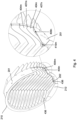
- Fig. 4 illustrates the vent with a cutaway to better show an essential feature of the invention, namely the openings between the flat portions of the blades and the inner perimeter of the frame. These openings allow the water to run from the flat portions onto the inner perimeter 202.
- louvres in vents are arranged to be horizontal between the frame edges, also shown in Fig. 1 , and there are no openings between the blades and the frame of the vent. Rain will therefore simply fall off the blades on the rainy side of the vent, typically in a drip-wise fashion.
- Fig. 4 illustrates edges of blade elements 404m and 404n attached to the frame 201.
- the openings that separate the flat portions from the frame are visible in the drawings (also for blade elements below blade elements 404m and 404n).
- the right-hand side of the drawing shows blade elements 404m and 404n in more detail, including their respective attachment points 407m and 407n. Focusing first on blade 404n, arrow 409n illustrates an opening between the ridge portion of the blade and the frame 201. Little water actually drains away this far up the ridge, but the opening allows any water there to do so. Note that this opening is optional.
- the arrow 410m illustrates the essential feature that at an end of the blade, the first substantially flat portion is at least partly separated from the inner perimeter by an opening allowing water to drain from the first substantially flat portion onto the inner perimeter.
- the circle at the end of the arrow 410m shows the first substantially flat portion as well as the opening.
- openings are also visible in the front view in Fig. 3 , where it can be seen that these openings in the present case actually form a ring-shaped opening through the vent along the inner perimeter, interrupted by the attachment of the blades to the frame.
- Fig. 5a shows droplets 522 that illustrate a droplets and mist of water created at the impact of rain 521.
- These droplets/mist tend to move into the vent, away from the rainy side, due to the air movement. It turns out that essentially none of these droplets/mist gets through the vent, even at a rainfall any one is likely to encounter. Instead, it gets into contact with the blades and run along the bottom side of the blades towards the inner perimeter, as illustrated by drop 523. Finally, a relatively small amount of water fall onto the blade below, as illustrated by drop 525. Again, by virtue of the slanted configuration of the blade, this drop will travel towards the inner perimeter, through the opening, and downwards.
- Fig. 5a also illustrates another feature of the present embodiment.
- a drain 212 that receives water from the inner perimeter of the frame through openings 436. From there, the water drains into a duct and to an outlet 437 pointing downwards.
- This drain provides an important effect: Although the vent performs well without the duct drain, water may be able to travel through the vent, forced by wind.
- the duct has the advantage that it provides wind cover for water at the bottom of the vent, thereby preventing the water from being blown inwards.
- Fig. 5b illustrates blades 504a, 504b, 504c in an embodiment where the blades are arranged in such a way that there is a straight through-going opening between pairs of adjacent blades.
- the drawing shall not be construed as being drawn to scale, the scale in Fig. 5b does indicate that even with straight through-going openings, rain in unlikely to get through the vent in a straight line. Most likely, the interaction with the blade will be similar to that in Fig. 5a .
- Fig. 5b illustrates a height, d o , of a straight through-going vent opening between two adjacent blades.
- a blade height, d h of one of the blades is also illustrated.
- the height of the straight through-going vent opening is at most 20 % of the height of the blade.
- the depth of the blade, d l (i.e. its "length" in the air flow direction, which is also the length of the cross-section) influences what opening height can be accepted. The longer the blades, relative to their height, the higher the opening between blades can be without rain being able to get through the vent and leaving the vent inwards. Almost any rain will be slowed by the blades and drain off towards the inner perimeter and downwards.
- Fig. 5c illustrates another embodiment 591 of the invention.
- the ridge is not rounded as in Fig. 5a , but instead has an edge.
- This embodiment does provide good cover against rain, but the edge at the ridge creates more acoustic noise than the rounded ridge shown in Fig. 5a .
- the embodiment does not have a drain similar to that in Fig. 5a , but this is straightforward to add.
- Fig. 5d illustrates yet another embodiment 592 of the vent.
- the blades have a valley rather than a ridge between the first and second substantially flat portions. Intuition might tell some that this vent is more efficient in draining rain. This is actually not the case, by any means.
- An important reason for the lower efficiency is that water is collected in the valley portion. Rain that enters then splashes into the rain collected in the valley portion, and the geometry allows drops from such splashes to travel further into the vent, a process that is enhanced by any wind that might be present.
- the effective depth of the valley portion is reduced by water present in the valley.
- the flat portions form straight inlets and outlets.
- wind tends to move horizontally.
- straight inlets and outlets results in the least amount of noise.
- Inlets in the prior art for instance those vents shown in Figs. 1 , 7 and 8 , have angled inlets. Presumably, the angled inlets are considered necessary to provide good cover against rain. It turns out that this is not the case, as the inventor of the present invention has found.
- Fig. 6 illustrates what takes place when the vent shown in Fig. 2 is exposed to winds and rain, as also illustrated in Fig. 5a .
- the reference numbers differ slightly where necessary.
- Wind 620 carrying rain 621 reaches the vent.
- the drops are slowed down and tend to gather on the first substantially flat portion 511, as illustrated by drops 622. From there, the drops move towards the perimeter, as illustrated by line 631, because the blades are slanted. Due to the openings between the first substantially flat parts and the inner perimeter (illustrated in detail in Fig. 4 ), the drops run onto the inner perimeter and downwards, as illustrated by line 632.
- Fig. 6 illustrates what takes place when the vent shown in Fig. 2 is exposed to winds and rain, as also illustrated in Fig. 5a .
- the reference numbers differ slightly where necessary.
- Wind 620 carrying rain 621 reaches the vent.
- the drops are slowed down and tend to gather on the first substantially flat portion 511, as illustrated by drops 622. From
- the water reaches the drain 212 through opening 436.
- the drain 212 acts as a duct, leading water towards the outlet 437 of the drain, as illustrated by line 633.
- Fig. 8 illustrates the cross-section of a conventional vent 800 similar to the one in Fig. 1 .
- the vent in Fig. 8 is more open, though, in the sense that the blades are less angled relative, and they are separated more. Not only is this vent not very rain-resistant, it also provides a relatively high air resistance compared to embodiments of the present invention described above.
- Fig. 9 is a comparison of the pressure drops at different air speeds across prior-art vent 800 ("1" in the legend), prior-art vent 700 ("4" in the legend), and embodiments 200 and 591 of the present invention ("2" and “3", respectively, in the legend). It is clear that the pressure drop across the prior-art vents is substantially higher than across the embodiments of the present invention, actually by a factor of around 2. For prior-art vent 700, which is highly rain resistant, the factor is around 3. This is in large part due to the straight inlets of the embodiments 200 and 591. This is a further advantage of these embodiments, on top of their ability to prevent rain from entering.
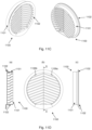
- Fig. 11A illustrates an embodiment of a vent kit in accordance with the invention.
- the kit comprises a vent element 1101 and a cover flange element 1102.
- Fig. 11B illustrates the elements in a sideview.
- Fig. 11A also illustrates fastening means 1105a, 1105b, and 1106a for rigidly assembling the vent element 1101 and flange element 1102 to one another, forming the vent.
- a screw or screws or threaded pin or pins may be inserted through vent element 1101 via hole or holes 1105a and 1105b, and attached in the fastening means 1106a (and 1106b, visible in Fig. 11D ) of flange element 1102.
- the fastening means 1106a, 1106b of the flange element 1102 are recesses comprising an internal threading for receiving a screw or threaded pin.
- Other fastening means can be used, as described previously in this specification.
- some embodiments of the vent kit comprises fasteners. Other embodiments do not.
- Fig. 11C illustrates a perspective front view and a perspective back view of the vent element 1101 and flange element 1102 assembled into a vent 1100. (Screws or similar means are not shown engaged into the fastening means of the vent element and flange element.)
- Fig. 11D(a) illustrates a cross-section A-A through the assembled vent 1100, A-A being defined in the front view Fig. 11D(b) . It can be seen that the blade cross-section resembles a half wave, having a trough in the left side of each blade and a crest/ridge on the right side (relative to Fig. 11D ).
- Fig. 11D(c) illustrates a sideview of the assembled vent 1100.
- a vent could also be made of a kit comprising two or more identical, or at least substantially identical, vent elements designed to provide, when assembled, a blade cross-section as described in relation to embodiments of the first aspect of the invention.
- a kit comprising two or more identical, or at least substantially identical, vent elements designed to provide, when assembled, a blade cross-section as described in relation to embodiments of the first aspect of the invention.
- Fig. 10A illustrates a vent kit in accordance with an embodiment of the invention in which there are several vent elements forming the blade cross-section.
- the kit comprises two vent elements 1001 and 1002, and a flange element 1003.
- Fig. 10B illustrates the elements in a sideview.
- vent element 1101 and flange element 1102 of the vent kit in Fig. 11A are different from the corresponding vent element 1002 and flange element 1003 in Fig. 10A . However, this is not essential in regards to the number of vent elements and/or the presence or absence of a separate flange element.
- the embodiment in Fig. 10A has fastening means 1005a, 1005b, 1006a, 1006b, 1007a for rigidly assembling the vent elements 1001, 1002 and the flange element 1003 to form the vent 1000 shown in Fig. 10C .
- a screw or screws or threaded pin or pins may be inserted through vent element 1001 via hole or holes 1005a and 1005b, then through corresponding holes 1006a and 1006b in vent element 1002, to finally be attached in the fastening means 1007a (and 1007b, visible in Fig. 10D(b) ) of flange element 1003.
- the fastening means 1007a, 1007b are recesses comprising an internal threading for receiving a screw or threaded pin.
- Other fastening means can be used, as described previously in this specification.
- vent element 1002 needs not have an internal threading, since it is clamped between vent element 1001 and flange element 1003. In case the vent elements are identical (or substantially identical), the vent element 1002 has the same threading as vent element 1001.
- Fig. 10C illustrates a perspective front view and a perspective back view of the vent elements 1001, 1002 and flange element 1003 assembled into a vent 1000. (Screws or similar means are not shown engaged into the fastening means of the vent elements 1001, 1002 and flange element 1003.)
- Fig. 10D(a) illustrates a cross-section A-A through the assembled vent 1000 (see definition of A-A in the front view Fig. 10D(b) ). It can be seen that the blade cross-sections of the vent elements 1001 and 1002 meet at the interface between the vent elements, thereby providing a blade cross-section similar to the one shown in Fig. 5a , and in accordance with the first aspect of the invention.
- the blades 204a and 204b are formed in single pieces.
- the embodiment in Fig. 11A provided a blade cross-section similar to a half wave
- the embodiment in Fig. 10A provides a full wave, being a combination of two half-wave vent elements 1001, 1002 arranged adjacent to one another in such a way that a "continuous" blade similar to the one in Fig. 5a results.
- Fig. 10D(c) illustrates a sideview of the assembled vent 1000.
- Fig. 12A illustrates a vent kit in accordance with an embodiment of the invention in which there are several vent elements that together form the vent blade cross-section, in a manner similar to Fig. 10A .
- the kit in Fig. 12A comprises three vent elements 1201, 1202, and 1203, and a flange element 1204.
- Fig. 12B illustrates the elements in a sideview.
- vent elements 1201, 1202 and 1203 are identical, but need not be.
- the vent elements 1201, 1202 and 1203 are identical to the vent element 1101 used in the vent kit in Fig. 11A for forming the vent 1100, shown in Fig. 11C .
- the flange element 1204 in Fig. 12A is identical to the flange element 1102 in Fig. 11A , but needs not be.
- the embodiment in Fig. 12A has fastening means 1205a, 1205b, 1206a, 1206b, 1207a, 1207b, 1208a and 1208b for rigidly assembling the vent elements 1201, 1202, 1203, and the flange element 1204 to form the vent 1200.
- a screw or screws or threaded pin or pins may be inserted through vent element 1201 via hole or holes 1205a and 1205b, then through corresponding holes 1206a and 1206b in vent element 1202, then through corresponding holes 1207a and 1207b in vent element 1203, to finally be attached in the fastening means 1208a (and 1208b, visible in Fig. 12D ) of flange element 1204.
- the fastening means 1208a, 1208b are recesses comprising an internal threading for receiving a screw or threaded pin. Other fastening means can be used, as described previously.
- vent element such as 1202 and/or 1203 need not have an internal threading, since it is clamped between vent element 1201 and flange element 1204.
- vent elements are identical (or substantially identical)
- the vent elements 1202 and 1203 would, however, have a threading identical to that of element 1201. This is therefore preferred from a cost perspective.
- Fig. 12C illustrates a perspective front view and a perspective back view of the vent elements 1201, 1202, 1203 and flange element 1204 assembled into a vent 1200. (Screws or similar means are not shown engaged into the fastening means of the vent elements 1201, 1202, 1203 and flange element 1204.)
- Fig. 12D(a) illustrates a cross-section A-A through the assembled vent 1200 (see definition of A-A in the front view Fig. 12D(b) ). It can be seen that the blade cross-sections of the vent elements 1201 and 1202 meet at the interface between the vent elements, providing a blade cross-section similar to the one shown in Fig. 5a and Fig. 10D(a) . In Fig. 5a , the blades 204a and 204b are formed in single pieces, as described in relation to Fig. 10D(a) .
- the embodiment in Fig. 11A provides a blade cross-section similar to a half wave, as shown in Fig. 11D(a) .
- the embodiment in Fig. 10A provides a blade cross-section similar to a full wave, being a combination of two half-wave vent elements 1001, 1002 arranged adjacent to one another in such a way that a "continuous" blade similar to the one in Fig. 5a results.
- Fig. 12D(a) the use of three vent elements 1201, 1202, 1203 result in a blade cross-section similar to one and a half wave. This results in an even high rejection of rain than that which is provided by the vent in Fig. 10C .
- Fig. 12D(c) illustrates a sideview of the assembled vent 1200.
Landscapes
- Engineering & Computer Science (AREA)
- Chemical & Material Sciences (AREA)
- Combustion & Propulsion (AREA)
- Mechanical Engineering (AREA)
- General Engineering & Computer Science (AREA)
- Civil Engineering (AREA)
- Structural Engineering (AREA)
- Specific Sealing Or Ventilating Devices For Doors And Windows (AREA)
- Arrangement Of Elements, Cooling, Sealing, Or The Like Of Lighting Devices (AREA)
Description
- The present invention relates to air vents. In particular, it relates to a vent, a method for mounting a vent, and a vent kit.
- Passive air vents are a common way to replace stale air with fresh air. Many state-of-the-art air vents are able to provide a high flow with relatively low noise while providing cover against for instance rain and birds, but have disadvantages.
- For instance, louvre-type vents are simple and provide some protection against rain, but they tend to be noisy, and they not particularly rainproof by any standard.
- Patent publication
CA 2,405,534 discloses a roof vent that comprises two parts, a cover and a conduit. The conduit, with a pipeline already attached, is said to be easily connected to the cover, after the cover has been installed on a roof. - The conduit will plug into the cover making installation "easy". The vent includes a channel or moat which surrounds the outlet of the conduit. Thus, if during extreme weather conditions, moisture passes into the cover from outside through its opening and if it gets past the door flap, the description claims that it will be trapped in the channel.
- Patent publication
US 2012/015596 relates to two devices that are used to let fresh air in or through a window or opening but at the same time keep rain or any other kind of precipitation out. It is stated that it is a device that will enable people to keep a window or an opening open even in inclement weather or when precipitation of any kind threatens to enter the opening or window. - Patent publication
GB 613,720 -
Document FR 2 529 929 A1 - In a first aspect, the invention provides a vent according to
claim 1. - A well-known vent not part of the invention illustrated schematically in
Fig. 1 comprisesblades frame 101. The vent also has acover flange 102 for fitting the vent against a surface, such as a wall. The blades are flat and arranged at an angle. This provides some protection against rain, which is illustrated aselement 121, but there is a significant amount of splashing when rain hits the blades, causing drops to get through the vent, as illustrated bydrops 122. Furthermore, the angling of the blades causes air to be redirected, resulting in an uneven pressure profile across the vent going from the top of the vent to the bottom of the vent inFig. 1 . -
Fig. 8 illustrates a cross-section of a vent not part of the invention similar to the one inFig. 1 , although thevent 800 inFig. 8 has blades that allow more rain to enter through the vent. Blades 803a, 803b, and 803c are separated so much that rain can pass between the blades relatively easily, especially in the presence of gusts. - Neither of the references mentioned in the "Background of the invention" section discloses the first substantially flat portion of a blade being at least partly separated from the inner perimeter of a frame by an opening allowing water to drain from the first substantially flat portion onto the inner perimeter.
- Examples of cross-sections in accordance with the present invention are shown in
Figs. 5a ,5c and 5d and will be discussed later in the specification. - The present invention differs from these known vents at least by comprising blades that are not flat, but have a flat portion followed by a ridge or valley portion. Vents in accordance with the present invention create significantly less noise, they may provide a significantly lower pressure drop, and they provide much better rain protection compared to the vents in
Figs. 1 and8 . Patent publicationCA 2,405,534 illustrates entirely flat blades and is therefore not remotely capable of providing the crucial effects provided by the present invention, for instance that of leading water to the perimeter for draining along the perimeter and at least partly inhibiting water from entering through the vent. InGB 613,720 US 2012/015596 also does not describe the blade shapes of the present invention. InUS 2012/015596 , blades are either substantially the same as known simple louvres, or they are not adapted to allow rain to drain onto an inner perimeter and drain along the inner perimeter, or the blades are not fixed on the inner perimenter of a frame in each end, and each blade is essentially a gutter, and water runs from gutter to gutter, zigzagging down near the middle of the vent seen from a front side. -
Fig. 7 illustrates anotherknown vent 700 which is not part of the invention, specifically designed to prevent rain from entering. Blades 703a, 703b, 703c are arranged in an array. The blades are configured withvarious appendages appendages air Fig. 7 at least in that the initial portion of the blades are substantially flat, i.e. without crooked appendages. - Not visible in
Figs. 1 ,7 and8 is the lack of an opening between the blades and the respective frames, which prevents water to drain to and along the inner perimeter. - Preferably, there is an opening at least 0.5 mm wide from the blade to the inner perimeter, such as at least 1 mm wide, such at least 1.5 mm wide, such as at least 2 mm wide. A larger distance allows a larger flow of water to drain from the blades onto the inner perimeters. However, if the distance is too large, rain will be able to travel along the inner perimeter, through the vent, at higher wind speeds.
- The ridge or valley portion helps capture rain. In fact, a ridge is preferred, as this provides a surprisingly effective protection against rain. The flatness of the initial part of the cross-section prevents creation of vortices, as opposed to the vent illustrated in
Fig. 7 . More importantly, however, the first substantially flat portion allows rain to run along the blade, towards the inner perimeter, and through the openings as described above. - In some embodiments, the first substantially flat portion of two adjacent blades are substantially parallel (such as parallel). This provides a smoother air flow through the vent.
- The cross-section is preferably taken as an intersection between said each blade and a plane which is perpendicular to a line extending from the first end of said each blade to the second end of said each blade.
Figs. 5a ,5c, 5d ,10D(a) ,11D(a) and12D(a) illustrate such cross-sections. - In some embodiments, the ridge or valley portion of the cross-section is followed by a second substantially flat portion forming a final part of the cross-section. Such a second substantially flat portion can be used to direct the air as desired, but more importantly, it can also assist in the draining away of water, just like the first substantially flat portion forming the initial part of the blade. In some embodiments, the second substantially flat portion of two adjacent blades are substantially parallel.
- The vent frame can have arbitrary shapes, such as circular or rectangular. This is a matter of design and could be determined by the specific hole in which the vent is should fit.
- When air impinges on a front side of a conventional vent along a surface-normal of the front side, air is redirected because the inlets formed by the blades in conventional vents are angled, as exemplified by the conventional vent shown in
Fig. 1 . The blades are angled to prevent rain from passing through the vent. - In some embodiments of the present invention, the first substantially flat portions of two adjacent blades in the vent form an inlet having an inlet direction that is substantially parallel to a surface normal of a front side of the vent, such as parallel to the surface normal. In some embodiments of the invention, the inlet direction deviates from the surface normal by at most 10 degrees.
- The vents in
Fig. 1 andFig. 7 have inlets directions that are angled away from the surface normal direction by about 45 degrees, and the vent inFig. 8 has inlet directions of approximately 34 degrees. Such large inlet angles seem to be accepted, even a norm. However, the inventor of the present invention found that surface-normal inlets can be used without compromising the vent's ability to drain away rain, at large volumes, especially when the surface-normal inlets are combined with the other features of the present invention. - In some embodiments of the present invention, the second substantially flat portions, if present, of two adjacent blades form an outlet having an outlet direction that is substantially parallel to the surface normal, such as parallel to surface normal. In some embodiments of the invention, the outlet direction deviates from the surface-normal axis by at most 10 degrees.
- In some embodiments of the invention, a height, do , of a straight through-going vent opening between two adjacent blades is at most 20 % of a height, dh, of one of the two adjacent blades. This reduces air resistance and yet allows for an effective protection against rain. Ultimately, however, it does allow rain to travel directly through the vent, which is not desirable, but high wind speed are necessary for that to happen. In some embodiments of the invention, the height, do , of the through-going opening is at most 10 % of the height, dh . This more effectively prevents rain from entering through the vent directly.
- In some embodiments of the invention, independent of whether there is a straight through-going opening between the blades or blade elements, or not, the depth of the blades or blade elements , dl, (i.e. the "length" in the blade or blade element in the air flow direction, which is also the length of the cross-section of the blade or blade element, as illustrated in the drawings) is preferably between 20 mm and 150 mm, such as between 50 mm and 150 mm, such as between 50 mm and 120 mm, such as between 50 mm and 100 mm.
- In some embodiments of the invention, a height of the blades or blade elements, dh, is between 5 mm and 50 mm, such as between 5 mm and 30 mm, such as between 10 mm and 30 mm.
- In some embodiments of the invention, there is no straight through-going opening between a pair of adjacent blades. This completely prevents rain from travelling straight through the pair of adjacent blades. Rain will encounter the blade surfaces and be slowed down. This slowdown provides for a very efficient draining, as the slower speed of the rain through the vent means that the rain has more time for draining away towards the inner perimeter.
- In some embodiments of the invention, the blade ridge part is smooth, i.e. has no appendages or edges that cause vortices, eddies, turbulence, or similar disturbances. This gives the smoothest and least noisy performance. In other embodiments of the invention, the blades have edges. For instance, the ridge may have an edge, for instance at the top of the ridge.
- In some embodiments of the invention, each blade is straight in a direction between the blade's first end and the blade's second end. This has some advantages, for instance ease of manufacturing. However, embodiments of the present invention should, in use, be arranged so that the blades are not horizontal, to make sure rain quickly drains towards the perimeter of the frame. This provides a fast and efficient draining.
- This is improved by providing blades that comprise a first blade element extending from the first end of the blade and a second blade element extending from the second end of the blade, the first and second blade elements being joined to one another at a joint position between the first and the second end of the blade, the first blade element being joined to the second blade element at an angle. Preferably, the first blade element is a mirror version of the second blade element, or at least substantially a mirror version. In other words, the blade is symmetrical around the joint position. Considered from the front, such blades are symmetric. This is aesthetically advantageous.
- Besides the differences already present between embodiments of the present invention and prior-art vents, the division of blades into two that are joined (at an angle) would be an unnecessary complication in prior-art vents and would therefore not be applied on prior-art vents.
- A smallest angle, α, between the blade elements of a blade is between 20 and 160 degrees, such as between 90 and 150 degrees, such as between 100 and 130 degrees. In some embodiments which are not part of the invention, the smallest angle is between 150 and 170 degrees. Note that there are two angles between the blade elements of a blade comprising two blade elements, namely the smallest angle, α, and the angle 360-α.
- In use, the blade elements are typically angled downwards from the joint position towards the frame. This, as well as the smallest angle, will be exemplified in more detail in the detailed description, see e.g.
Figs. 2 and 3 . - In some embodiments of the invention, the vent comprises a drain configured to carry water away from a bottom portion of the vent. In some embodiments of the invention, the drain comprises a duct having an inlet at said bottom portion of the vent to receive water from the inner perimeter of the vent and having an outlet configured to drain water out of the duct. The duct encloses the water, which shields the draining water from winds. This prevents water from being carried into the vent under higher wind speeds. This feature cannot be combined with prior-art vents, since water in prior-art vents is not led onto an inner perimeter of those vents. Water will simply slide off blades and fall under the influence of gravity and winds.
- Another form of drain may be used, such as an open conduit. However, the open conduit does not shield the water, and therefore water may be carried into the vent under high wind speeds.
- A second aspect of the invention provides a method for mounting a vent in accordance with the first aspect of the invention; the method being according to claim 9. The method comprises the features of claim 9, and in particular: arranging the vent in such a way that at least two of the blades or blade elements in the array of blades are slanted from horizontal by at least 10 degrees. If the vent is formed from blade elements, preferably all blade elements are slanted from horizontal by at least 10 degrees. If the blades in the vent are straight blades, the aesthetics might be negatively affected. However, the technical solution works well.
- Prior-art vents are not designed to be arranged in such a way. Prior-art vents have blades that are arranged to be horizontal. This gives the best protection against rain. Arranging a prior-art vent at an angle is therefore something the person skilled in the art would avoid.
- In some embodiments of the invention, the method of mounting comprises mounting a vent in which each blade comprises a first blade element extending from the first end of the blade and a second blade element extending from the second end of the blade, the first and second blade elements being joined to one another at a joint position between the first and the second end of the blade, the first blade element being joined to the second blade element at an angle, the vent having a symmetry axis when considered from a front side of the vent, the method of mounting comprising arranging the vent so that the first and second blade elements of each blade form substantially the same angle with respect to horizontal.
- An embodiment of the invention of this arrangement is shown in
Fig. 3 . Each blade element forms an angle of 30 degrees with respect to horizontal, as also described later in this specification. - A third aspect provides a vent kit according to
claim 10. - In some embodiments of the invention, a first vent element provides a first part of the blade cross-section, and a second vent element provides a second part of the blade cross-section, and the first and the second vent elements, when assembled, provide the entire blade cross-section, whereby a vent in accordance with an embodiment of the first aspect of the invention is provided.
- In some embodiments of the invention, the blade cross-section of at least two of the vent elements are identical, or substantially identical. Preferably, at least two of the vent elements are identical or at least substantially identical (i.e. not just in terms of their respective blade cross-sections). Substantially refers to the blade cross-sections being identical, but allowing for other features, such as fastening means (described below), material, finishing or other non-essential part of the vent element being different between the vent elements. It is obvious to the person skilled in the art that an insignificant change shall not render two vent elements non-identical.
- In some embodiments of the invention, each vent element comprises one or more attachment means/fasteners for firmly attaching the respective vent elements to one another to form the vent. One outermost vent element may for instance comprise a first part of a snap rivet, such as a male part of a snap rivet, and another outermost vent element may comprise a corresponding second part of the snap rivet, such as a female part of the snap rivet. Alternatively or additionally, two outermost vent elements comprise respective snap rivet parts of a snip snap rivet. When the snap rivet parts (male+female or snip snap parts) are engaged with one another, the vent in accordance with an embodiment of the first aspect of the invention is formed. The female part may be a through hole or it may be a recess comprising locking means corresponding to a male part. Outermost vent elements are for
instance element Fig. 10A , since they form each end of thevent 1000 shown inFig. 10C . Outermost vent elements are 1101 and 1102 inFig. 11A , since they form respective ends of thevent 1100 shown inFig. 11C . Outermost vent elements are 1201 and 1204 inFig. 12A , since they form respective ends of thevent 1200 shown inFig. 12C . - Alternatively or additionally, each vent element may comprise one or more holes aligned to allow the vent elements to be attached to one another by inserting fasteners such as for instance one or more screws or threaded pin or threaded pins or other threaded part or threaded parts through the one or more holes, or one or more nuts with bolts through the one or more holes, or one or more snap rivets. Other means of attaching the vent elements together to form the vent may also or alternatively be used. Combinations of different fastening means may also be used. Generally, it is implicit that the fastening means of the vent elements and the cover flange element, if present, are aligned appropriately. Otherwise, a vent in accordance with an embodiment of the first aspect of the invention would not be provided. Thus, the feature "aligned" is not used further in this specification.
- If screws or threaded pins or other threaded parts are used, then the suitable internal threading is provided in at least one of the vent elements. For instance, at least one of the outermost vent elements may have an internal threading, and the other outermost vent element has a bearing surface for supporting a screw head of a screw fitting the internal threading, or both outermost vent elements have internal threading for receiving for instance a threaded pin, preferably one that comprises a slot for easy driving. When a screw is used, one outermost vent element needs not have a through hole; a recess comprising internal threading is sufficient for allow attachment of the vent elements to one another.
- Latch systems, such as a toggle latch, is another attachment means that may be used to attach the vent elements to one another. A catch arranged on one vent element can be caught by a latch arranged on another of the vent elements, thereby holding the vent elements together to form the vent.
- Alternatively, the vent parts may be glued or welded together (using a welding method suitable for the material from which the vent elements are made).
- In some embodiments of the invention, the kit comprises a separate cover flange element to be firmly attached onto another vent element to produce a vent having a flange for fitting the vent into for instance a hole in a wall. The flange may shield the perimeter of the hole in the wall from for instance rain. In some embodiments, the cover flange element comprises attachment means as described above for the vent elements. As such, the cover flange element is an outermost vent element of the kit. The attachment means described above apply equally well to the cover flange element for attaching it to the other vent elements in the kit.
- In some embodiments of the invention, the cover flange element has a drain part that, when the vent is assembled, provides the drain in accordance with some embodiments of the first aspect of the invention. In some embodiments of the invention, the drain part of the cover flange element comprises a duct having an inlet at the bottom portion of the vent to receive water from the inner perimeter of the vent and having an outlet configured to drain water out of the duct, away from the blades and flange element.
- In some embodiments of the invention, the flange is part of a vent element, i.e. an element that provides a part of the complete blade cross-section of the vent.
- In some embodiments of the invention, the cover flange element provides the bottom portion of the vent.
- A particular vent kit comprises only a single vent element and one cover flange element. The considerations above that apply to embodiments of the third aspect also apply to this particular vent. The single vent element forms the entire blade cross-section.
-
-
Figure 1 illustrates a conventional louvre -
Figure 2 illustrates a perspective vent in accordance with an embodiment of the invention. -
Figure 3 illustrates a front view of the vent shown inFigure 2 . -
Figure 4 is a detailed view of ends of the blades in the vent shown inFigure 2 . -
Figure 5a illustrates a cross-section of blades in the vent shown inFigure 2 . -
Figure 5b is a detail view of a cross-section of blades in an alternative embodiment of the invention. -
Figure 5c is a detail view of a cross-section of blades in another alternative embodiment of the invention. -
Figure 5d is a detail view of a cross-section of blades in yet another alternative embodiment of the invention. -
Figure 6 illustrate flow of rain capture by the vent shown inFigure 2 . -
Figure 7 illustrates a prior-art vent not part of the present invention that can capture rain. -
Figure 8 illustrates another conventional louvre vent not part of the present invention. -
Figure 9 illustrates pressure drop for various types of vents, including known vents and vents in accordance with embodiments of the present invention. -
Figures 10A-10D illustrate a vent kit in accordance with an embodiment of the invention. -
Figures 11A-11D illustrate a vent kit in accordance with an embodiment of the invention. -
Figures 12A-12D illustrate a vent kit in accordance with an embodiment of the invention. - In the following, the invention is described in terms of specific embodiments and with reference to the accompanying drawings.
-
Fig. 2 illustrates avent 200 in accordance with an embodiment of the invention. It comprises aframe 201 having aninner perimeter 202.Blades frame 201 at respective attachment points. In this view, it can be seen thatblades respective points cover flange 210 for engaging with a wall or similar surface to fit the vent relatively tightly to the surface. The vent furthermore has adrain 212 for draining away water that runs to the bottom of the vent. - Each blade in the vent in this embodiment consists of two elements. One blade consists of
blade element 203a that meetsblade element 204a at the horizontal midpoint of the vent. Similarly, the blade below it consists ofblade elements blade elements Blade element 203a is angled downwards in a direction towards its attachment point at the frame. Similarly, correspondingblade element 204a is angled downwards in a direction towards its (visible)attachment point 207a. The same applies forblade element 203b andcorresponding blade element 204b, and forblade element 203c andcorresponding blade element 204c. The angling of the blade elements means that water impinging on the blades will run down the blades by means of gravity. -
Fig. 3 is a front view of the vent. The figure specifically illustrates a smallest angle, α, betweencorresponding blade elements References - The symmetrical construction of the vent described above provides an aesthetically non-provoking look. Asymmetric vents sometimes annoy some observers. However, a lack of symmetry is not detrimental to the effect of the vent, which will still perform well even if the blade elements do not form approximately the same angle with respect to horizontal.
- The vent works well within a large range of values of the angle α. An angle as small as 10 degrees from horizontal for the blade elements still provides a very large draining effect. However, below that, the draining effect is substantially reduced. On the other hand, blades that are closer to vertical, i.e. where the angle between the blade elements is e.g. 20 degrees (i.e. α=20 degrees) will also be effective, but the aesthetic aspect suffers somewhat in this configuration.
-
Fig. 5a illustrates the various parts of the blade cross-sections that characterize this specific embodiment of the invention.Fig. 5a is a cross-section down through the middle of the vent inFig. 2 .Blade portion 511 is the first substantially flat portion that forms the initial part of the cross-section of each blade. This portion is followed by aridge portion 512. This particular embodiment comprises the optional feature of the ridge portion of the cross-section being followed by a second substantially flat portion forming a final part of the cross-section. (If the second substantially flat portion is not present, the ridge portion forms the final part of the cross-section.) Note that sinceportion 512 is a ridge, the will be an upward gradient between the first substantially flat portion and the ridge portion, and a downward gradient from the ridge potion to the second substantially flat portion. -
Fig. 5a illustrates an important feature of the present embodiment, namely that rain is not able to pass through the vent without getting into contact with the vent.Arrow 560 illustrates the closest water moving in a straight line would get to travelling directly through the vent. However, because of the shape of the blades and distance between them,rain 521 has no chance but to hit a surface of the blades, where it will break into smaller drops.Fig. 5a illustratesdrops 524 that have run down the ridge toward the rainy side. As will be described below, these drops will also move "into" the page. This is because the blade element that supports them is slanted, as for instanceFig. 3 shows. The drops run to the inner perimeter, through the openings between the flat parts and the inner perimeter, and downwards along the inner perimeter. This will described in more detail in relation toFig. 6 later in this specification. -
Fig. 4 illustrates the vent with a cutaway to better show an essential feature of the invention, namely the openings between the flat portions of the blades and the inner perimeter of the frame. These openings allow the water to run from the flat portions onto theinner perimeter 202. Conventionally, louvres in vents are arranged to be horizontal between the frame edges, also shown inFig. 1 , and there are no openings between the blades and the frame of the vent. Rain will therefore simply fall off the blades on the rainy side of the vent, typically in a drip-wise fashion. -
Fig. 4 illustrates edges ofblade elements frame 201. The openings that separate the flat portions from the frame are visible in the drawings (also for blade elements belowblade elements blade elements blade 404n,arrow 409n illustrates an opening between the ridge portion of the blade and theframe 201. Little water actually drains away this far up the ridge, but the opening allows any water there to do so. Note that this opening is optional. - Focusing next on
blade 404m, thearrow 410m illustrates the essential feature that at an end of the blade, the first substantially flat portion is at least partly separated from the inner perimeter by an opening allowing water to drain from the first substantially flat portion onto the inner perimeter. The circle at the end of thearrow 410m shows the first substantially flat portion as well as the opening. - These openings are also visible in the front view in
Fig. 3 , where it can be seen that these openings in the present case actually form a ring-shaped opening through the vent along the inner perimeter, interrupted by the attachment of the blades to the frame. -
Fig. 5a showsdroplets 522 that illustrate a droplets and mist of water created at the impact ofrain 521. These droplets/mist tend to move into the vent, away from the rainy side, due to the air movement. It turns out that essentially none of these droplets/mist gets through the vent, even at a rainfall any one is likely to encounter. Instead, it gets into contact with the blades and run along the bottom side of the blades towards the inner perimeter, as illustrated bydrop 523. Finally, a relatively small amount of water fall onto the blade below, as illustrated bydrop 525. Again, by virtue of the slanted configuration of the blade, this drop will travel towards the inner perimeter, through the opening, and downwards. -
Fig. 5a also illustrates another feature of the present embodiment. At the bottom of the vent, there is adrain 212 that receives water from the inner perimeter of the frame throughopenings 436. From there, the water drains into a duct and to anoutlet 437 pointing downwards. This drain provides an important effect: Although the vent performs well without the duct drain, water may be able to travel through the vent, forced by wind. The duct has the advantage that it provides wind cover for water at the bottom of the vent, thereby preventing the water from being blown inwards. -
Fig. 5b illustratesblades Fig. 5b does indicate that even with straight through-going openings, rain in unlikely to get through the vent in a straight line. Most likely, the interaction with the blade will be similar to that inFig. 5a . -
Fig. 5b illustrates a height, do , of a straight through-going vent opening between two adjacent blades. A blade height, dh, of one of the blades is also illustrated. Preferably, the height of the straight through-going vent opening is at most 20 % of the height of the blade. However, the depth of the blade, dl, (i.e. its "length" in the air flow direction, which is also the length of the cross-section) influences what opening height can be accepted. The longer the blades, relative to their height, the higher the opening between blades can be without rain being able to get through the vent and leaving the vent inwards. Almost any rain will be slowed by the blades and drain off towards the inner perimeter and downwards. -
Fig. 5c illustrates anotherembodiment 591 of the invention. Here, the ridge is not rounded as inFig. 5a , but instead has an edge. This embodiment does provide good cover against rain, but the edge at the ridge creates more acoustic noise than the rounded ridge shown inFig. 5a . The embodiment does not have a drain similar to that inFig. 5a , but this is straightforward to add. -
Fig. 5d illustrates yet anotherembodiment 592 of the vent. Here the blades have a valley rather than a ridge between the first and second substantially flat portions. Intuition might tell some that this vent is more efficient in draining rain. This is actually not the case, by any means. An important reason for the lower efficiency is that water is collected in the valley portion. Rain that enters then splashes into the rain collected in the valley portion, and the geometry allows drops from such splashes to travel further into the vent, a process that is enhanced by any wind that might be present. Furthermore, the effective depth of the valley portion is reduced by water present in the valley. - In all the embodiments in
Figs. 5a to 5d , the flat portions form straight inlets and outlets. On average, wind tends to move horizontally. When arranged vertically with the two sides of the vent arranged to be vertical, straight inlets and outlets results in the least amount of noise. Inlets in the prior art, for instance those vents shown inFigs. 1 ,7 and8 , have angled inlets. Presumably, the angled inlets are considered necessary to provide good cover against rain. It turns out that this is not the case, as the inventor of the present invention has found. -
Fig. 6 illustrates what takes place when the vent shown inFig. 2 is exposed to winds and rain, as also illustrated inFig. 5a . The reference numbers differ slightly where necessary.Wind 620 carryingrain 621 reaches the vent. When rain comes into contact with the blades, the drops are slowed down and tend to gather on the first substantiallyflat portion 511, as illustrated by drops 622. From there, the drops move towards the perimeter, as illustrated byline 631, because the blades are slanted. Due to the openings between the first substantially flat parts and the inner perimeter (illustrated in detail inFig. 4 ), the drops run onto the inner perimeter and downwards, as illustrated byline 632. As described in relation toFig. 5a , very little water gets past theridge 512, as illustrated by the few and small drops 623. Furthermore, those drops are effectively stopped or at least slowed down, and will be carried to the inner perimeter via the second substantiallyflat portion 513. As described above, the major part of those drops attach to the underside of the blade above the drops and runs towards the perimeter. - Finally, at the bottom of the vent, the water reaches the
drain 212 throughopening 436. Thedrain 212 acts as a duct, leading water towards theoutlet 437 of the drain, as illustrated byline 633. -
Fig. 8 illustrates the cross-section of aconventional vent 800 similar to the one inFig. 1 . The vent inFig. 8 is more open, though, in the sense that the blades are less angled relative, and they are separated more. Not only is this vent not very rain-resistant, it also provides a relatively high air resistance compared to embodiments of the present invention described above. -
Fig. 9 is a comparison of the pressure drops at different air speeds across prior-art vent 800 ("1" in the legend), prior-art vent 700 ("4" in the legend), andembodiments art vent 700, which is highly rain resistant, the factor is around 3. This is in large part due to the straight inlets of theembodiments -
Fig. 11A illustrates an embodiment of a vent kit in accordance with the invention. The kit comprises avent element 1101 and acover flange element 1102.Fig. 11B illustrates the elements in a sideview. -
Fig. 11A also illustrates fastening means 1105a, 1105b, and 1106a for rigidly assembling thevent element 1101 andflange element 1102 to one another, forming the vent. A screw or screws or threaded pin or pins may be inserted throughvent element 1101 via hole orholes Fig. 11D ) offlange element 1102. In the present example, the fastening means 1106a, 1106b of theflange element 1102 are recesses comprising an internal threading for receiving a screw or threaded pin. Other fastening means can be used, as described previously in this specification. Generally, some embodiments of the vent kit comprises fasteners. Other embodiments do not. -
Fig. 11C illustrates a perspective front view and a perspective back view of thevent element 1101 andflange element 1102 assembled into avent 1100. (Screws or similar means are not shown engaged into the fastening means of the vent element and flange element.) -
Fig. 11D(a) illustrates a cross-section A-A through the assembledvent 1100, A-A being defined in the front viewFig. 11D(b) . It can be seen that the blade cross-section resembles a half wave, having a trough in the left side of each blade and a crest/ridge on the right side (relative toFig. 11D ). -
Fig. 11D(c) illustrates a sideview of the assembledvent 1100. - The inventor found that a vent could also be made of a kit comprising two or more identical, or at least substantially identical, vent elements designed to provide, when assembled, a blade cross-section as described in relation to embodiments of the first aspect of the invention. By combining several such identical vent elements, an increasingly extensive blade cross-section is provided when the vent elements are assembled. In this way, it is possible to provide highly waterproof vents at a relatively low cost. By increasing the number of vent elements in a kit, the assembled vent will be increasingly waterproof.
- Accordingly,
Fig. 10A illustrates a vent kit in accordance with an embodiment of the invention in which there are several vent elements forming the blade cross-section. The kit comprises twovent elements flange element 1003.Fig. 10B illustrates the elements in a sideview. - Note that the
vent element 1101 andflange element 1102 of the vent kit inFig. 11A are different from thecorresponding vent element 1002 andflange element 1003 inFig. 10A . However, this is not essential in regards to the number of vent elements and/or the presence or absence of a separate flange element. - Similar to the embodiment in
Fig. 11A , the embodiment inFig. 10A has fastening means 1005a, 1005b, 1006a, 1006b, 1007a for rigidly assembling thevent elements flange element 1003 to form thevent 1000 shown inFig. 10C . A screw or screws or threaded pin or pins may be inserted throughvent element 1001 via hole orholes holes vent element 1002, to finally be attached in the fastening means 1007a (and 1007b, visible inFig. 10D(b) ) offlange element 1003. In the present example, the fastening means 1007a, 1007b are recesses comprising an internal threading for receiving a screw or threaded pin. Other fastening means can be used, as described previously in this specification. - The
vent element 1002 needs not have an internal threading, since it is clamped betweenvent element 1001 andflange element 1003. In case the vent elements are identical (or substantially identical), thevent element 1002 has the same threading asvent element 1001. -
Fig. 10C illustrates a perspective front view and a perspective back view of thevent elements flange element 1003 assembled into avent 1000. (Screws or similar means are not shown engaged into the fastening means of thevent elements flange element 1003.) -
Fig. 10D(a) illustrates a cross-section A-A through the assembled vent 1000 (see definition of A-A in the front viewFig. 10D(b) ). It can be seen that the blade cross-sections of thevent elements Fig. 5a , and in accordance with the first aspect of the invention. InFig. 5a , theblades - Whereas the embodiment in
Fig. 11A provided a blade cross-section similar to a half wave, the embodiment inFig. 10A provides a full wave, being a combination of two half-wave vent elements Fig. 5a results. -
Fig. 10D(c) illustrates a sideview of the assembledvent 1000. -
Fig. 12A illustrates a vent kit in accordance with an embodiment of the invention in which there are several vent elements that together form the vent blade cross-section, in a manner similar toFig. 10A . The kit inFig. 12A comprises threevent elements flange element 1204.Fig. 12B illustrates the elements in a sideview. - In this example, the
vent elements vent elements vent element 1101 used in the vent kit inFig. 11A for forming thevent 1100, shown inFig. 11C . Furthermore, theflange element 1204 inFig. 12A is identical to theflange element 1102 inFig. 11A , but needs not be. - Similar to the embodiments in
Figs. 10A and11A , the embodiment inFig. 12A has fastening means 1205a, 1205b, 1206a, 1206b, 1207a, 1207b, 1208a and 1208b for rigidly assembling thevent elements flange element 1204 to form thevent 1200. A screw or screws or threaded pin or pins may be inserted throughvent element 1201 via hole orholes holes vent element 1202, then through correspondingholes vent element 1203, to finally be attached in the fastening means 1208a (and 1208b, visible inFig. 12D ) offlange element 1204. In the present example, the fastening means 1208a, 1208b are recesses comprising an internal threading for receiving a screw or threaded pin. Other fastening means can be used, as described previously. - The vent element such as 1202 and/or 1203 need not have an internal threading, since it is clamped between
vent element 1201 andflange element 1204. In case the vent elements are identical (or substantially identical), thevent elements element 1201. This is therefore preferred from a cost perspective. -
Fig. 12C illustrates a perspective front view and a perspective back view of thevent elements flange element 1204 assembled into avent 1200. (Screws or similar means are not shown engaged into the fastening means of thevent elements flange element 1204.) -
Fig. 12D(a) illustrates a cross-section A-A through the assembled vent 1200 (see definition of A-A in the front viewFig. 12D(b) ). It can be seen that the blade cross-sections of thevent elements Fig. 5a andFig. 10D(a) . InFig. 5a , theblades Fig. 10D(a) . - The embodiment in
Fig. 11A provides a blade cross-section similar to a half wave, as shown inFig. 11D(a) . The embodiment inFig. 10A provides a blade cross-section similar to a full wave, being a combination of two half-wave vent elements Fig. 5a results. InFig. 12D(a) , the use of threevent elements Fig. 10C . -
Fig. 12D(c) illustrates a sideview of the assembledvent 1200.
Claims (13)
- A vent (200), comprising:- a support frame (101) having an inner perimeter (202),- a set of blades (203a,203b,203c,204a,204b,204c) arranged in an array, wherein- each blade comprises a first blade element extending from a first end (206a, 206b, 206c) of the blade and a second blade element extending from a second end (207a, 207b, 207c) of the blade, the first and second blade elements being joined to one another at a joint position between the first and the second ends of the blade, the first blade element being joined to the second blade element at an angle, wherein a smallest angle between the blade elements of a blade is between 20 and 160 degrees;- the first end (206a, 206b, 206c) of each blade is attached to a corresponding first part of the frame, and the second end (207a, 207b, 207c) of each blade is attached to a corresponding second part of the frame;- a first substantially flat portion (511) forms an initial part of a cross-section of each blade, and the first substantially flat portion (511) is followed by a ridge or valley portion (512); and- at the first end (206a, 206b, 206c) and second end (207a, 207b, 207c) of each blade, the first substantially flat portion (511) is at least partly separated from the inner perimeter by an opening (410m) allowing water to drain from the first substantially flat portion (511) onto the inner perimeter (202).
- A vent in accordance with claim 1, wherein said cross-section of each blade is an intersection between said each blade and a plane which is perpendicular to a line extending from the first end of said each blade to the second end of said each blade.
- A vent in accordance with claims 1 or 2, wherein the first substantially flat portion (511) of two adjacent blades (203a, 203b, 204a, 204b) are substantially parallel, wherein the ridge or valley portion (512) is followed by a second substantially flat portion (513) forming a final part of the cross-section, and wherein the second substantially flat portions (513) of two adjacent blades are substantially parallel.
- A vent in accordance with any of the preceding claims, wherein the first substantially flat portions of two adjacent blades are substantially parallel and form an inlet having an inlet direction that is substantially parallel to a surface normal to a front side of the vent, and wherein the second substantially flat portions of two adjacent blades form an outlet having an outlet direction that is substantially parallel to a surface normal to the front side of the vent.
- A vent in accordance with one of the preceding claims, wherein a height of a straight through-going vent opening between two adjacent blades is at most 20 % of a height of one of the two adjacent blades or wherein between a pair of adjacent blades there is no straight through-going opening.
- A vent in accordance with one of the preceding claims, wherein a smallest angle between the blade elements of a blade is between 90 and 150 degrees.
- A vent in accordance with one of the preceding claims, wherein each blade is symmetrical around the joint position.
- A vent in accordance with one of the preceding claims, further comprising a drain configured to carry water away from a bottom portion of the vent, wherein the drain comprises a duct having an inlet at said bottom portion to receive water from the bottom portion and having an outlet end configured to drain water out of the duct, wherein the duct is configured to enclose water from the drain inlet to the drain outlet.
- A method for mounting a vent in accordance with one of claims 1-8 in a duct, the method comprising: arranging the vent in such a way that at least two of the blades or blade elements in the array of blades are slanted from horizontal by at least 10 degrees, the vent has an axis of symmetry when considered from a front side of the vent, and the method comprises arranging the vent so that the first and second blade elements of each blade form substantially the same angle with 3 respect to horizontal.
- A vent kit comprising- at least one vent element (1001, 1002, 1101, 1201, 1202, 1203) and a cover flange element (1003, 1102, 1204) comprising fastening means (1005a, 1005b, 1006a, 1006b, 1007a, 1007b, 1105a, 1105b, 1106a, 1106b) via which they are configured to be rigidly assembled using corresponding one or more fasteners to form a vent (200),and wherein at least one vent element is a vent according to claim 1 and wherein its first substantially flat portion (511) is followed by a ridge or valley portion (512) thereby forming a cross-section with a half-wave form.
wherein each vent element comprises:- a support frame (101) having an inner perimeter (202),- a set of blades (203a,203b,203c,204a,204b,204c) arranged in an array, wherein- each blade comprises a first blade element extending from a first end (206a, 206b, 206c) of the blade and a second blade element extending from a second end (207a, 207b, 207c) of the blade, the first and second blade elements being joined to one another at a joint position between the first and the second end of the blade, the first blade element being joined to the second blade element at an angle, wherein a smallest angle between the blade elements of a blade is between 20 and 160 degrees;- the first end (206a, 206b, 206c) of each blade is attached to a corresponding first part of the frame, and the second end (207a, 207b, 207c) of each blade is attached to a corresponding second part of the frame; - A vent kit in accordance with claim 10, wherein the cover flange element is configured for engaging with a wall surface when the assembled vent is inserted into a wall.
- A vent kit in accordance with any of claims 10-11, wherein the cover flange element comprises a drain part that, when the vent is assembled, provides a drain, and wherein the drain part comprises a duct having an inlet at the bottom portion of the vent to receive water from the inner perimeter of the vent and having an outlet configured to drain water out of the duct, away from the blades and the cover flange element.
- A vent kit in accordance with any of claims 10-12, wherein the fastening means comprise one or more through holes in each of the vent elements for maintaining the vent elements rigidly attached to one another using corresponding one or more fasteners, and the cover flange element, if present, comprises a recess or through hole for maintaining the vent elements and cover flange element rigidly attached to one another using corresponding one or more fasteners, wherein at least one of the fasteners is a rivet or snap rivet or wherein the fastening means in the vent elements and the fastening means in the cover flange element, if present, comprise an internal threading, and at least one of the fasteners is a screw or threaded pin corresponding to the threading.
Applications Claiming Priority (3)
| Application Number | Priority Date | Filing Date | Title |
|---|---|---|---|
| EP17157506.1A EP3367013A1 (en) | 2017-02-22 | 2017-02-22 | Air vent |
| EP17202399 | 2017-11-17 | ||
| PCT/EP2018/054416 WO2018154003A2 (en) | 2017-02-22 | 2018-02-22 | Air vent |
Publications (2)
| Publication Number | Publication Date |
|---|---|
| EP3586068A2 EP3586068A2 (en) | 2020-01-01 |
| EP3586068B1 true EP3586068B1 (en) | 2024-05-15 |
Family
ID=61622517
Family Applications (1)
| Application Number | Title | Priority Date | Filing Date |
|---|---|---|---|
| EP18710347.8A Active EP3586068B1 (en) | 2017-02-22 | 2018-02-22 | Air vent and method for mounting said air vent |
Country Status (4)
| Country | Link |
|---|---|
| US (1) | US20200284466A1 (en) |
| EP (1) | EP3586068B1 (en) |
| CN (2) | CN108457579A (en) |
| WO (1) | WO2018154003A2 (en) |
Families Citing this family (4)
| Publication number | Priority date | Publication date | Assignee | Title |
|---|---|---|---|---|
| CN109339671A (en) * | 2018-09-18 | 2019-02-15 | 袁长勃 | A kind of round or quadrangle list double deflection grille device |
| US20210003313A1 (en) * | 2019-07-03 | 2021-01-07 | Mestek, Inc. | Louver assembly |
| CN112227916A (en) * | 2020-09-16 | 2021-01-15 | 深圳供电局有限公司 | Shutter blade and shutter |
| CN113339920A (en) * | 2021-05-26 | 2021-09-03 | 中国建筑第八工程局有限公司 | Ventilation structure of main body structure and construction method thereof |
Family Cites Families (12)
| Publication number | Priority date | Publication date | Assignee | Title |
|---|---|---|---|---|
| GB613720A (en) * | 1946-06-27 | 1948-12-02 | Cecil Gordon Vokes | Improvements in or relating to ventilating openings |
| US3782050A (en) * | 1971-06-16 | 1974-01-01 | Dowco Corp | Louver assembly having improved weatherproofing and air flow characteristics |
| GB1583995A (en) * | 1976-06-05 | 1981-02-04 | Colt Int Ltd | Ventilators |
| CH658509A5 (en) * | 1982-07-09 | 1986-11-14 | Multisafe Ag | PROTECTIVE GRILLE. |
| CA2405534C (en) | 1999-08-13 | 2003-10-14 | Dundas Jafine Inc. | Roof vent |
| JP2002061466A (en) * | 2000-08-24 | 2002-02-28 | Ote Technological Engineering Corp | Vertical waterproof louver |
| US20080119127A1 (en) * | 2006-11-19 | 2008-05-22 | Dane Stewart | Programmable air register kit |
| GB2465029A (en) * | 2008-11-11 | 2010-05-12 | Fabrice Andre Jean-Claude Goodale | Collapsible cover for securing over the end of a vent duct |
| US10386090B2 (en) | 2010-07-14 | 2019-08-20 | Zhihua Fang | Reconfigurable system allowing air flow through an open window while blocking precipitation |
| DE202011106891U1 (en) * | 2011-10-19 | 2012-01-20 | Uemet Gmbh Uebigauer Metallverarbeitung | Ventilation insert, in particular for transformer stations |
| GB2511148B (en) * | 2013-06-18 | 2017-11-15 | Vkr Holding As | Grill arrangement |
| CN103557574B (en) * | 2013-10-28 | 2016-05-04 | 太仓莫迪思能源工程有限公司 | A kind of Novel ventilation system weather shield device |
-
2017
- 2017-12-22 CN CN201711402445.2A patent/CN108457579A/en active Pending
-
2018
- 2018-02-22 CN CN201880013361.6A patent/CN110325799B/en active Active
- 2018-02-22 WO PCT/EP2018/054416 patent/WO2018154003A2/en active Search and Examination
- 2018-02-22 US US16/487,898 patent/US20200284466A1/en not_active Abandoned
- 2018-02-22 EP EP18710347.8A patent/EP3586068B1/en active Active
Also Published As
| Publication number | Publication date |
|---|---|
| WO2018154003A3 (en) | 2018-10-18 |
| CN110325799A (en) | 2019-10-11 |
| US20200284466A1 (en) | 2020-09-10 |
| EP3586068A2 (en) | 2020-01-01 |
| WO2018154003A2 (en) | 2018-08-30 |
| CN108457579A (en) | 2018-08-28 |
| CN110325799B (en) | 2021-05-11 |
Similar Documents
| Publication | Publication Date | Title |
|---|---|---|
| EP3586068B1 (en) | Air vent and method for mounting said air vent | |
| EP1408174B1 (en) | Gutter shield for eaves trough | |
| US6427388B1 (en) | Gutter shield | |
| US6944992B2 (en) | Gutter shield | |
| US7950187B2 (en) | Roof gutter cover section with water draining upper surface | |
| US7765743B2 (en) | Corner gutter screen assembly | |
| EP1227201B1 (en) | Gutter shield | |
| US4956948A (en) | Clog resistant gutter-downspout connection unit | |
| US8286390B2 (en) | Removable downspout for a gutter system | |
| US5542224A (en) | Louver | |
| US20040118052A1 (en) | Rounded eaves trough with a gutter shield | |
| US20060037255A1 (en) | Half round with hooks | |
| KR101435007B1 (en) | Noise reduction Louver | |
| US20050210758A1 (en) | Roof gutter cover section with water draining upper surface | |
| US20080070494A1 (en) | Dormer roof ventilator and method thereof | |
| EP3367013A1 (en) | Air vent | |
| US7836637B2 (en) | Valley diverter for a gutter cover | |
| EP3274634B1 (en) | Vent | |
| US11035124B2 (en) | Gutter insert | |
| JP3542333B2 (en) | Ventilation cutting edge and external wall construction structure using it | |
| US20060037254A1 (en) | Half round with hooks | |
| GB2529553A (en) | Drained louvres and method of making drained louvres | |
| JPH06221633A (en) | Cover device for ventilation port | |
| US6708453B1 (en) | Gutter protection system | |
| CA2364602C (en) | Gutter shield |
Legal Events
| Date | Code | Title | Description |
|---|---|---|---|
| STAA | Information on the status of an ep patent application or granted ep patent |
Free format text: STATUS: UNKNOWN |
|
| STAA | Information on the status of an ep patent application or granted ep patent |
Free format text: STATUS: THE INTERNATIONAL PUBLICATION HAS BEEN MADE |
|
| PUAI | Public reference made under article 153(3) epc to a published international application that has entered the european phase |
Free format text: ORIGINAL CODE: 0009012 |
|
| STAA | Information on the status of an ep patent application or granted ep patent |
Free format text: STATUS: REQUEST FOR EXAMINATION WAS MADE |
|
| 17P | Request for examination filed |
Effective date: 20190904 |
|
| AK | Designated contracting states |
Kind code of ref document: A2 Designated state(s): AL AT BE BG CH CY CZ DE DK EE ES FI FR GB GR HR HU IE IS IT LI LT LU LV MC MK MT NL NO PL PT RO RS SE SI SK SM TR |
|
| AX | Request for extension of the european patent |
Extension state: BA ME |
|
| DAV | Request for validation of the european patent (deleted) | ||
| DAX | Request for extension of the european patent (deleted) | ||
| STAA | Information on the status of an ep patent application or granted ep patent |
Free format text: STATUS: EXAMINATION IS IN PROGRESS |
|
| 17Q | First examination report despatched |
Effective date: 20210525 |
|
| STAA | Information on the status of an ep patent application or granted ep patent |
Free format text: STATUS: EXAMINATION IS IN PROGRESS |
|
| GRAP | Despatch of communication of intention to grant a patent |
Free format text: ORIGINAL CODE: EPIDOSNIGR1 |
|
| STAA | Information on the status of an ep patent application or granted ep patent |
Free format text: STATUS: GRANT OF PATENT IS INTENDED |
|
| GRAS | Grant fee paid |
Free format text: ORIGINAL CODE: EPIDOSNIGR3 |
|
| INTG | Intention to grant announced |
Effective date: 20240314 |
|
| GRAA | (expected) grant |
Free format text: ORIGINAL CODE: 0009210 |
|
| STAA | Information on the status of an ep patent application or granted ep patent |
Free format text: STATUS: THE PATENT HAS BEEN GRANTED |
|
| AK | Designated contracting states |
Kind code of ref document: B1 Designated state(s): AL AT BE BG CH CY CZ DE DK EE ES FI FR GB GR HR HU IE IS IT LI LT LU LV MC MK MT NL NO PL PT RO RS SE SI SK SM TR |
|
| REG | Reference to a national code |
Ref country code: CH Ref legal event code: EP Ref country code: GB Ref legal event code: FG4D |
|
| REG | Reference to a national code |
Ref country code: DE Ref legal event code: R096 Ref document number: 602018069469 Country of ref document: DE |