EP3585627B1 - Fahrzeugluftreifen - Google Patents
Fahrzeugluftreifen Download PDFInfo
- Publication number
- EP3585627B1 EP3585627B1 EP18701418.8A EP18701418A EP3585627B1 EP 3585627 B1 EP3585627 B1 EP 3585627B1 EP 18701418 A EP18701418 A EP 18701418A EP 3585627 B1 EP3585627 B1 EP 3585627B1
- Authority
- EP
- European Patent Office
- Prior art keywords
- flank
- rib
- profile
- recesses
- vehicle tyre
- Prior art date
- Legal status (The legal status is an assumption and is not a legal conclusion. Google has not performed a legal analysis and makes no representation as to the accuracy of the status listed.)
- Active
Links
Images

Classifications
-
- B—PERFORMING OPERATIONS; TRANSPORTING
- B60—VEHICLES IN GENERAL
- B60C—VEHICLE TYRES; TYRE INFLATION; TYRE CHANGING; CONNECTING VALVES TO INFLATABLE ELASTIC BODIES IN GENERAL; DEVICES OR ARRANGEMENTS RELATED TO TYRES
- B60C11/00—Tyre tread bands; Tread patterns; Anti-skid inserts
- B60C11/03—Tread patterns
- B60C11/13—Tread patterns characterised by the groove cross-section, e.g. for buttressing or preventing stone-trapping
- B60C11/1307—Tread patterns characterised by the groove cross-section, e.g. for buttressing or preventing stone-trapping with special features of the groove walls
-
- B—PERFORMING OPERATIONS; TRANSPORTING
- B60—VEHICLES IN GENERAL
- B60C—VEHICLE TYRES; TYRE INFLATION; TYRE CHANGING; CONNECTING VALVES TO INFLATABLE ELASTIC BODIES IN GENERAL; DEVICES OR ARRANGEMENTS RELATED TO TYRES
- B60C11/00—Tyre tread bands; Tread patterns; Anti-skid inserts
- B60C11/03—Tread patterns
- B60C11/13—Tread patterns characterised by the groove cross-section, e.g. for buttressing or preventing stone-trapping
- B60C11/1307—Tread patterns characterised by the groove cross-section, e.g. for buttressing or preventing stone-trapping with special features of the groove walls
- B60C11/1323—Tread patterns characterised by the groove cross-section, e.g. for buttressing or preventing stone-trapping with special features of the groove walls asymmetric
-
- B—PERFORMING OPERATIONS; TRANSPORTING
- B60—VEHICLES IN GENERAL
- B60C—VEHICLE TYRES; TYRE INFLATION; TYRE CHANGING; CONNECTING VALVES TO INFLATABLE ELASTIC BODIES IN GENERAL; DEVICES OR ARRANGEMENTS RELATED TO TYRES
- B60C11/00—Tyre tread bands; Tread patterns; Anti-skid inserts
- B60C11/03—Tread patterns
- B60C11/0306—Patterns comprising block rows or discontinuous ribs
-
- B—PERFORMING OPERATIONS; TRANSPORTING
- B60—VEHICLES IN GENERAL
- B60C—VEHICLE TYRES; TYRE INFLATION; TYRE CHANGING; CONNECTING VALVES TO INFLATABLE ELASTIC BODIES IN GENERAL; DEVICES OR ARRANGEMENTS RELATED TO TYRES
- B60C11/00—Tyre tread bands; Tread patterns; Anti-skid inserts
- B60C11/03—Tread patterns
- B60C11/0318—Tread patterns irregular patterns with particular pitch sequence
-
- B—PERFORMING OPERATIONS; TRANSPORTING
- B60—VEHICLES IN GENERAL
- B60C—VEHICLE TYRES; TYRE INFLATION; TYRE CHANGING; CONNECTING VALVES TO INFLATABLE ELASTIC BODIES IN GENERAL; DEVICES OR ARRANGEMENTS RELATED TO TYRES
- B60C11/00—Tyre tread bands; Tread patterns; Anti-skid inserts
- B60C11/03—Tread patterns
- B60C2011/0337—Tread patterns characterised by particular design features of the pattern
- B60C2011/0339—Grooves
- B60C2011/0341—Circumferential grooves
-
- B—PERFORMING OPERATIONS; TRANSPORTING
- B60—VEHICLES IN GENERAL
- B60C—VEHICLE TYRES; TYRE INFLATION; TYRE CHANGING; CONNECTING VALVES TO INFLATABLE ELASTIC BODIES IN GENERAL; DEVICES OR ARRANGEMENTS RELATED TO TYRES
- B60C11/00—Tyre tread bands; Tread patterns; Anti-skid inserts
- B60C11/03—Tread patterns
- B60C2011/0337—Tread patterns characterised by particular design features of the pattern
- B60C2011/0339—Grooves
- B60C2011/0341—Circumferential grooves
- B60C2011/0353—Circumferential grooves characterised by width
-
- B—PERFORMING OPERATIONS; TRANSPORTING
- B60—VEHICLES IN GENERAL
- B60C—VEHICLE TYRES; TYRE INFLATION; TYRE CHANGING; CONNECTING VALVES TO INFLATABLE ELASTIC BODIES IN GENERAL; DEVICES OR ARRANGEMENTS RELATED TO TYRES
- B60C11/00—Tyre tread bands; Tread patterns; Anti-skid inserts
- B60C11/03—Tread patterns
- B60C2011/0337—Tread patterns characterised by particular design features of the pattern
- B60C2011/0339—Grooves
- B60C2011/0341—Circumferential grooves
- B60C2011/0355—Circumferential grooves characterised by depth
-
- B—PERFORMING OPERATIONS; TRANSPORTING
- B60—VEHICLES IN GENERAL
- B60C—VEHICLE TYRES; TYRE INFLATION; TYRE CHANGING; CONNECTING VALVES TO INFLATABLE ELASTIC BODIES IN GENERAL; DEVICES OR ARRANGEMENTS RELATED TO TYRES
- B60C11/00—Tyre tread bands; Tread patterns; Anti-skid inserts
- B60C11/03—Tread patterns
- B60C2011/0337—Tread patterns characterised by particular design features of the pattern
- B60C2011/0386—Continuous ribs
- B60C2011/039—Continuous ribs provided at the shoulder portion
-
- B—PERFORMING OPERATIONS; TRANSPORTING
- B60—VEHICLES IN GENERAL
- B60C—VEHICLE TYRES; TYRE INFLATION; TYRE CHANGING; CONNECTING VALVES TO INFLATABLE ELASTIC BODIES IN GENERAL; DEVICES OR ARRANGEMENTS RELATED TO TYRES
- B60C11/00—Tyre tread bands; Tread patterns; Anti-skid inserts
- B60C11/03—Tread patterns
- B60C11/13—Tread patterns characterised by the groove cross-section, e.g. for buttressing or preventing stone-trapping
- B60C11/1307—Tread patterns characterised by the groove cross-section, e.g. for buttressing or preventing stone-trapping with special features of the groove walls
- B60C2011/133—Tread patterns characterised by the groove cross-section, e.g. for buttressing or preventing stone-trapping with special features of the groove walls comprising recesses
-
- B—PERFORMING OPERATIONS; TRANSPORTING
- B60—VEHICLES IN GENERAL
- B60C—VEHICLE TYRES; TYRE INFLATION; TYRE CHANGING; CONNECTING VALVES TO INFLATABLE ELASTIC BODIES IN GENERAL; DEVICES OR ARRANGEMENTS RELATED TO TYRES
- B60C2200/00—Tyres specially adapted for particular applications
- B60C2200/06—Tyres specially adapted for particular applications for heavy duty vehicles
Definitions
- the invention relates to a pneumatic vehicle tire, in particular a commercial vehicle tire, with a tread with two shoulder-side tread ribs, each of which is separated from a central tread area by a wide circumferential groove running straight around in the circumferential direction, the circumferential groove having a rounded groove base and at the respective
- the shoulder-side profile rib is bounded by a rib flank, with recesses formed on the rib flank of the circumferential groove at the profile rib periphery, which in the direction of the extent of the circumferential groove have an extension length of a maximum of 30 mm and in each case in plan view L-shaped to one another and extending in the radial direction and have a bottom surface, wherein, viewed in plan view, the first boundary surface extends into the profile rib at an angle of up to 35 ° to the axial direction and the second boundary surface u nter an angle of 90 ° to 125 ° to the first-mentioned boundary surface.
- a pneumatic vehicle tire of the type mentioned is for example from EP 2 447 092 A1 known.
- the tread of this tire has two shoulder-side tread ribs with a block-like structure, on the rib flanks of which recesses are formed on the tread rib periphery.
- the recesses each have a bottom surface designed as an inclined surface and, in plan view, L-shaped to one another, extending in the radial direction, the boundary surfaces enclosing an angle of 90 ° with one another.
- the recesses formed one behind the other have a sawtooth-like profile.
- the extension length of the recesses in the direction of extension of the circumferential groove is, for example, 5 mm.
- the invention is based on the object of taking constructive measures by means of which the traction performance of a tire with a tread with tread ribs in the shoulder areas can be improved.
- the extension length of the recesses is 70% to 90% of the profile depth
- the bottom surface of the recesses is at a depth of 15% to 25% of the profile depth
- the boundary surfaces of the recesses running in the axial direction provide very effective traction edges on the profile rib periphery.
- the profile ribs are well stabilized by the second, almost circumferential, boundary surfaces and the bottom surfaces located at a relatively shallow depth, so that the formation of tears in the area of the recesses is largely avoided.
- the rib flank is composed in the circumferential direction of flank sections which run at an acute angle of 1 ° to 3 ° to the circumferential direction, the flank sections being connected to one another via recesses which are each formed by the first delimiting surface of the recesses .
- flank sections connected via recesses Another advantage of these flank sections connected via recesses is that the first delimiting surface can be designed in the radial direction along the recess as an elongated triangular surface up to the start of the groove base. A traction edge therefore always remains in the area of the recess, even if the tread is worn away.
- the pneumatic vehicle tire has tread blocks in the central tread area which are designed according to a method of pitch length variation and correspondingly follow one another in the circumferential direction, a flank section of the rib flank being assigned to each pitch.
- This arrangement of the flank sections according to the pitch length variation provided in the central tread area is also advantageous for the tire / road noise.
- the width of the transition surface is 1.0 mm to 3.0 mm. This narrow transition surface is advantageous for the stability of the rib flank in this area.
- Pneumatic vehicle tires designed according to the invention are, in particular, off-the-road tires or commercial vehicle tires for a wide variety of purposes, preferably large commercial vehicle tires for rim diameters of at least 24 inches. Such tires are, for example, tires for straddle carriers, reach stackers or container stackers. Tires designed according to the invention have a single or multi-layer carcass, either as a radial carcass or as a diagonal carcass, and a multi-layer belt structure or several breaker layers.
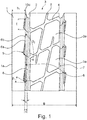
- the profiled tread shown in the figures has a tread rib 1 on each shoulder side, each of which is separated from a central tread region 3 by a wide circumferential groove 2 running in the circumferential direction.
- the profile ribs 1 have no or largely no profile structures, such as transverse grooves or incisions, and have a width bi of 20% to 30% of the floor contact area width B.
- the floor contact area width B corresponds to the axial distance between the two outer edge edges 1a of the profile ribs 1 .
- the tread has in the central tread region 3 a block structure with tread blocks 3a which are separated from one another by transverse grooves 4 and oblique grooves 5 running at a small acute angle to the circumferential direction. Since the block structure in the central tread area 3 is not the subject of the invention, its design will not be discussed in detail.
- the central one The tread area 3 is designed according to a method of pitch length variation, each pitch comprising a pair of the adjacent professional blocks 3a in the central tread area 3 together with one of the transverse grooves 4 adjoining them in the circumferential direction.
- pitches are provided in different circumferential lengths, for example in two to three different circumferential lengths, in order in this way to favorably influence or reduce the tire / road noise.
- At least the circumferential grooves 2 have a depth which corresponds to the intended profile depth T ( Fig. 2 ), which in the case of commercial vehicle tires can vary within a wide range, for example 12 mm to 95 mm, depending on their tire dimensions and intended use.
- each circumferential groove 2 on the profile rib 1 is bounded by a rib flank 6, opposite to the rib flank 6 by block flanks 7 following one another in the circumferential direction.
- the rib flank 6 and the block flanks 7 are connected to one another via a groove base 8, which in the embodiment shown and how it is common for circumferential grooves to be rounded.
- the rib flank 6 is also composed of flank sections 6a in the circumferential direction, the edge edges 6b of which extend to the circumferential direction at an acute angle ⁇ of 1 ° to 3 °, at least largely the same for all flank sections 6a.
- a flank section 6a is assigned to each pitch in the central tread area 3.
- the inner tread end points of the flank sections 6a each lie on the same straight line running around in the circumferential direction. The same applies to the end points of the flank sections 6a on the outside of the tread. Between the flank sections 6a following one another in the circumferential direction there is therefore a small nose or a short recess in the marginal edges 6b.
- each recess 9 On each rib flank 6, at the profile rib periphery, there are formed in the profile rib 1 protruding, L-shaped recesses 9 in plan view.
- the recesses 9 are located at the end sections of the flank sections 6a and therefore end at the recesses.
- the main boundary surfaces of each recess 9 are boundary surfaces 10a, 10b that extend L-shaped to one another in plan view and extend in the radial direction, and a bottom surface 11 that essentially has the shape of an elongated triangle in plan view.
- the boundary surface 10a also forming the recess, runs from the rib flank 6 in plan view at an angle ⁇ 1 of 0 ° to 35 ° to the axial direction
- the boundary surface 10b which adjoins the boundary surface 10a, runs at an angle ⁇ 2 to the boundary surface 10a, which is 90 ° to 125 °.
- the boundary surface 10b ends at a narrow transition surface 10d to the rib flank 6.
- the two boundary surfaces 10a, 10b also run in the radial direction or to the radial direction at a small acute angle ⁇ ( Fig. 3 ) of up to 10 °.
- the transition surface 10d extends in the radial direction to the bottom surface 11, in plan view in the axial direction and has a width of a few mm, in particular 1.0 mm to 3.0 mm, in the axial direction.
- the extension length 1 ( Fig. 1 ) the recess 9 at the tread periphery is 70% to 90% of the profile depth T, but a maximum of 30 mm.
- the bottom surface 11 is at a depth t ( Fig. 2 ) from 15% to 25% of the profile depth T and merges into the boundary surfaces 10a, 10d via transition curves. In the The preferred embodiment shown is also designed to be rounded between the two boundary surfaces 10a, 10b.
- the boundary surface 10a is in the radial direction as an elongated narrow triangular surface 10c ( Fig. 2 ) continued to the bottom of the groove 8.
- the height h determined in the radial direction ( Fig. 2 ) between the acute-angled end of the triangular surface 10c and the profile rib periphery is therefore 70% to 90% of the profile depth T.
Landscapes
- Engineering & Computer Science (AREA)
- Mechanical Engineering (AREA)
- Tires In General (AREA)
Description
- Die Erfindung betrifft einen Fahrzeugluftreifen, insbesondere Nutzfahrzeugreifen, mit einem Laufstreifen mit zwei schulterseitigen Profilrippen, welche jeweils durch eine breite und auf Profiltiefe ausgeführte, in Umfangsrichtung gerade umlaufende Umfangsrille von einem zentralen Laufstreifenbereich getrennt sind, wobei die Umfangsrille einen gerundeten Rillengrund aufweist und an der jeweiligen schulterseitigen Profilrippe von einer Rippenflanke begrenzt ist, wobei an der Rippenflanke der Umfangsrille bei der Profilrippenperipherie Ausnehmungen ausgebildet sind, welche in Richtung der Erstreckung der Umfangsrille eine Erstreckungslänge von maximal 30 mm und jeweils in Draufsicht L-förmig zueinander verlaufende und sich in radialer Richtung erstreckende Begrenzungsflächen und eine Bodenfläche aufweisen, wobei, in Draufsicht betrachtet, die erste Begrenzungsfläche unter einem Winkel von bis zu 35° zur axialer Richtung in die Profilrippe hinein verläuft und die zweite Begrenzungsfläche unter einem Winkel von 90° bis 125° zur erstgenannten Begrenzungsfläche verläuft.
- Nutzfahrzeugreifen mit derartigen Profilausgestaltungen sind in unterschiedlichen Varianten bekannt. Im zentralen Laufstreifenbereich können weitere Umfangsrillen, welche Profilrippen voneinander trennen, verlaufen. Der zentrale Laufstreifenbereich kann ferner mit einer Blockstruktur, beispielsweise mit zwei oder drei Blockreihen, strukturiert sein, es kann auch eine Kombination von Profilrippen und Blöcken im zentralen Laufstreifenbereich vorgesehen sein. Nutzfahrzeugreifen mit derart ausgestalteten Laufstreifen haben sich vor allem an nachlaufenden Achspositionen von Nutzfahrzeugen oder an Positionen von Nutzfahrzeugen bewährt, an welchen relativ geringe laterale Bewegungen stattfinden. Ein gewisser Nachteil von derart umfangsorientiert ausgeführten Laufstreifen mit Profilrippen an Reifenschultern und mit an diese angrenzenden breiten Umfangsrillen ist die geringe Traktion in Folge nicht vorhandener Eingriffskanten.
- Ein Fahrzeugluftreifen der eingangs genannten Art ist beispielsweise aus der
EP 2 447 092 A1 bekannt. Der Laufstreifen dieses Reifens weist zwei blockartig strukturierte schulterseitige Profilrippen auf, an deren Rippenflanken an der Profilrippenperipherie Ausnehmungen ausgebildet sind. Die Ausnehmungen weisen jeweils eine als Schrägfläche ausgebildete Bodenfläche und in Draufsicht L-förmig zueinander verlaufende, sich in radialer Richtung erstreckende Begrenzungsflächen auf, wobei die Begrenzungsflächen miteinander einen Winkel von 90° einschließen. In Sicht auf die jeweilige Rippenflanke betrachtet, weisen die hintereinander ausgebildeten Ausnehmungen ein sägezahnartiges Profil auf. Die Erstreckungslänge der Ausnehmungen in Richtung der Erstreckung der Umfangsrille beträgt beispielsweise 5 mm. - Aus der
WO 2007 099 085 A1 ist ein Fahrzeugluftreifen mit einem Laufstreifen mit zwei mittleren Profilrippen bekannt, welche jeweils von in Draufsicht asymmetrisch und langgezogen Z-förmig verlaufenden Einschnitten durchquert sind. Solche Einschnitte sollen gute Griffeigenschaften auf nassen und auf schneebedeckten Fahrbahnen ermöglichen, ohne dass die Fahreigenschaften auf trockener Fahrbahn verschlechtert werden. - Der Erfindung liegt die Aufgabe zugrunde, konstruktive Maßnahmen zu treffen, mittels welcher sich die Traktionsperformance eines Reifens mit einem Laufstreifen mit Profilrippen in den Schulterbereichen verbessern lässt.
- Gelöst wird die gestellte Aufgabe erfindungsgemäß dadurch, dass die Erstreckungslänge der Ausnehmungen 70 % bis 90 % der Profiltiefe beträgt, sich die Bodenfläche der Ausnehmungen in einer Tiefe von 15% bis 25% der Profiltiefe befindet und wobei zwischen der Rippenflanke und der zweiten Begrenzungsfläche der Ausnehmung eine in radialer Richtung verlaufende Übergangsfläche vorhanden ist, welche in Draufsicht in axialer Richtung oder unter einem spitzen Winkel von bis zu 45° zur axialen Richtung verläuft und welche in axialer Richtung eine Breite von mindestens 1,0 mm aufweist.
- Insbesondere die in axialer Richtung verlaufenden Begrenzungsflächen der Ausnehmungen stellen an der Profilrippenperipherie sehr wirksame Traktionskanten zur Verfügung. Durch die zweiten, nahezu in Umfangsrichtung verlaufenden Begrenzungsflächen sowie die in einer relativ geringen Tiefe befindlichen Bodenflächen werden die Profilrippen gleichzeitig gut stabilisiert, so dass das Entstehen von Einrissen im Bereich der Ausnehmungen weitgehend vermieden wird.
- Bei einer bevorzugten Ausführungsform der Erfindung setzt sich die Rippenflanke in Umfangsrichtung aus Flankenabschnitten zusammen, die zur Umfangsrichtung unter einem spitzen Winkel von 1° bis 3° verlaufen, wobei die Flankenabschnitte über Rücksprünge miteinander verbunden sind, welche jeweils von der ersten Begrenzungsfläche der Ausnehmungen mitgebildet sind. Ein vorteilhafter Effekt dieser zur Umfangsrichtung unter einem kleinen spitzen Winkel verlaufenden Flankenabschnitte ist deren Beitrag zur Traktion.
- Ein weiterer Vorteil dieser über Rücksprünge verbundenen Flankenabschnitte besteht darin, dass die erste Begrenzungsfläche in radialer Richtung entlang des Rücksprunges als langestreckte Dreiecksfläche bis zum Beginn des Rillengrundes ausgebildet werden kann. Auch bei größerem Abrieb des Laufstreifens bleibt daher im Bereich des Rücksprunges immer eine Traktionskante vorhanden.
- In einer bevorzugten Ausführungsform weist der Fahrzeugluftreifen im zentralen Laufstreifenbereich Profilblöcke auf, die gemäß einem Verfahren der Pitchlängenvariation ausgestaltet sind und in Umfangsrichtung entsprechend aufeinander folgen, wobei jedem Pitch ein Flankenabschnitt der Rippenflanke zugeordnet: ist. Diese Anordnung der Flankenabschnitte gemäß der im mittleren Laufstreifenbereich vorgesehenen Pitchlängenvariation ist für das Reifen/Fahrbahngeräusch ebenfalls vorteilhaft.
- Bei einer weiteren. bevorzugten Ausführungsvariante der Erfindung beträgt die Breite der Übergangsfläche 1,0 mm bis 3,0 mm. Diese schmale Übergangsfläche ist für die Stabilität der Rippenflanke in diesem Bereich von Vorteil.
- Weitere Merkmale, Vorteile und Einzelheiten der Erfindung werden nun anhand der Zeichnung, die ein Ausführungsbeispiel darstellt, näher beschrieben. Dabei zeigen
-
Fig. 1 eine Draufsicht auf einen Umfangsabschnitt eines Ausführungsbeispiels eines Laufstreifens eines erfindungsgemäßen Fahrzeugluftreifens, -
Fig. 2 eine Ansicht eines Umfangsabschnittes einer Profilrippenflanke und -
Fig. 3 eine Vorderansicht eines Umfangsabschnitt einer Umfangsrille mit Sicht auf die Profilrippenflanke. - Erfindungsgemäß ausgeführte Fahrzeugluftreifen sind insbesondere Off-The-Road-Reifen oder Nutzfahrzeugreifen für unterschiedlichste Einsatzzwecke, vorzugsweise groß dimensionierte Nutzfahrzeugreifen für Felgendurchmesser von mindestens 24 Zoll. Solche Reifen sind beispielsweise Reifen für Portalhubwagen, Reachstacker oder Containerstapler. Erfindungsgemäß ausgeführte Reifen weisen eine ein-oder mehrlagige Karkasse, entweder als Radialkarkasse oder als Diagonalkarkasse, und einen mehrlagigen Gürtelverband oder mehrere Breakerlagen auf.
- Der in den Figuren gezeigte profilierte Laufstreifen weist schulterseitig je eine Profilrippe 1 auf, die jeweils von einer breiten, in Umfangsrichtung umlaufenden Umfangsrille 2 von einem zentralen Laufstreifenbereich 3 getrennt sind. Die Profilrippen 1 weisen keine oder weitgehend keine Profilstrukturen, wie Querrillen oder Einschnitte, auf und besitzen eine Breite bi von 20% bis 30% der Bodenaufstandsflächenbreite B. Die Bodenaufstandsflächenbreite B entspricht dabei dem in axialer Richtung ermittelten Abstand der beiden äußeren Randkanten 1a der Profilrippen 1.
- Bei der dargestellten Ausführung weist der Laufstreifen im zentralen Laufstreifenbereich 3 eine Blockstruktur mit Profilblöcken 3a auf, die durch Querrillen 4 und unter einem kleinen spitzen Winkel zur Umfangsrichtung verlaufende Schrägrillen 5 voneinander getrennt sind. Nachdem die Blockstruktur im zentralen Laufstreifenbereich 3 nicht Gegenstand der Erfindung ist wird auf ihre Ausgestaltung im Detail nicht eingegangen. Der zentrale Laufstreifenbereich 3 ist nach einem Verfahren der Pitchlängenvariation ausgelegt, wobei jedes Pitch ein Paar der nebeneinander befindlichen Profiblöcke 3a im zentralen Laufstreifenbereich 3 mitsamt jeweils einer der an diese in Umfangsrichtung anschließenden Querrille 4 umfasst. Wie an sich bekannt und üblich werden solche Pitches in unterschiedlichen Umfangslängen, beispielsweise in zwei bis drei unterschiedlichen Umfangslängen, vorgesehen, um derart das Reifen/Fahrbahngeräusch günstig zu beeinflussen bzw. zu vermindern.
- Zumindest die Umfangsrillen 2 weisen eine Tiefe auf, die der vorgesehenen Profiltiefe T (
Fig. 2 ) entspricht, die bei Nutzfahrzeugreifen je nach deren Reifendimension und Einsatzzweck in einen weiten Bereich variieren kann, beispielsweise 12 mm bis 95 mm betragen kann. - Wie beispielsweise
Fig. 3 zeigt, ist jede Umfangsrille 2 an der Profilrippe 1 von einer Rippenflanke 6 begrenzt, gegenüber der Rippenflanke 6 von in Umfangsrichtung aufeinander folgenden Blockflanken 7. Die Rippenflanke 6 und die Blockflanken 7 sind über einen Rillengrund 8 miteinander verbunden, welcher bei der gezeigten Ausführung und wie es bei Umfangsrillen üblich ist, gerundet ausgeführt ist. Bei der gezeigten Ausführung setzt sich ferner die Rippenflanke 6 in Umfangsrichtung aus Flankenabschnitten 6a zusammen, deren Randkanten 6b zur Umfangsrichtung unter einem für alle Flankenabschnitten 6a zumindest weitgehend gleich großen spitzen Winkel α von 1° bis 3° verlaufen. Bei der gezeigten Ausführung ist jedem Pitch im zentralen Laufstreifenbereich 3 ein Flankenabschnitt 6a zugeordnet. In Draufsicht betrachtet, liegen die laufstreifeninneren Endpunkte der Flankenabschnitte 6a jeweils auf derselben in Umfangsrichtung umlaufenden Geraden. Analoges gilt für die laufstreifenäußeren Endpunkte der Flankenabschnitte 6a. Zwischen den in Umfangrichtung aufeinander folgenden Flankenabschnitten 6a ist daher eine kleine Nase bzw. ein kurzer Rücksprung in den Randkanten 6b vorhanden. - An jeder Rippenflanke 6 sind, bei der Profilrippenperipherie, in die Profilrippe 1 hineinragende, in Draufsicht L-förmige Ausnehmungen 9 ausgebildet. Die Ausnehmungen 9 befinden sich an den Endabschnitten der Flankenabschnitte 6a und enden daher an den Rücksprüngen. Die hauptsächlichen Begrenzungsflächen jeder Ausnehmung 9 sind in Draufsicht L-förmig zueinander verlaufende und sich in radialer Richtung erstreckende Begrenzungsflächen 10a, 10b und eine Bodenfläche 11, die in Draufsicht im Wesentlichen die Gestalt eines langgestreckten Dreieckes aufweist. Die Begrenzungsfläche 10a verläuft, den Rücksprung mitbildend, von der Rippenflanke 6 ausgehend in Draufsicht unter einem Winkel β1 von 0° bis 35° zur axialen Richtung, die Begrenzungsfläche 10b, die an die Begrenzungsfläche 10a anschließt, verläuft unter einem Winkel β2 zur Begrenzungsfläche 10a, welcher 90° bis 125° beträgt. Die Begrenzungsfläche 10b endet an einer schmalen Übergangsfläche 10d zur Rippenflanke 6. Die beiden Begrenzungsflächen 10a, 10b verlaufen ferner in radialer Richtung bzw. zur radialen Richtung unter einem kleinen spitzen Winkel γ (
Fig. 3 ) von bis zu 10°. Die Übergangsfläche 10d verläuft in radialer Richtung bis zur Bodenfläche 11, in Draufsicht in axialer Richtung und weist in axialer Richtung eine Breite von wenigen mm, insbesondere 1,0 mm bis 3,0 mm auf. Die Erstreckungslänge 1 (Fig. 1 ) der Ausnehmung 9 an der Laufstreifenperipherie beträgt 70 % bis 90 % der Profiltiefe T, jedoch maximal 30 mm. Die Bodenfläche 11 befindet sich in einer Tiefe t (Fig. 2 ) von 15% bis 25% der Profiltiefe T und geht über Übergangsrundungen in die Begrenzungsflächen 10a, 10d über. Bei der gezeigten, bevorzugten Ausführung ist ferner auch das Inneneck zwischen den beiden Begrenzungsflächen 10a, 10b gerundet ausgeführt. - Am Rücksprung zwischen den Flankenabschnitten 6a ist die Begrenzungsfläche 10a in radialer Richtung als langgestreckte schmale Dreieckfläche 10c (
Fig. 2 ) bis zum Rillengrund 8 fortgesetzt. Die in radialer Richtung ermittelte Höhe h (Fig. 2 ) zwischen dem spitzwinkeligen Ende der Dreieckfläche 10c und der Profilrippenperipherie beträgt daher 70% bis 90% der Profiltiefe T. -
- 1 .......................
- Profilrippe
- 1a .....................
- Randkante
- 2 .......................
- Umfangsrille
- 3 .......................
- Laufstreifenbereich
- 3a .....................
- Profilblock
- 4 .......................
- Querrille
- 5 .......................
- Schrägrille
- 6 .......................
- Rippenflanke
- 6a .....................
- Flankenabschnitt
- 6b .....................
- Randkante
- 7 .......................
- Blockflanke
- 8 .......................
- Rillengrund
- 9 .......................
- Ausnehmung
- 10a, 10b ...........
- Begrenzungsfläche
- 10c ...................
- Dreieckfläche
- 10d ...................
- Übergangsfläche
- 11 .....................
- Bodenfläche
- B ......................
- Bodenaufstandsflächenbreite
- T .......................
- Profiltiefe
- b1 ......................
- Breite
- h .......................
- Höhe
- l ........................
- Länge
- t ........................
- Tiefe
- α, β1, β2 ............
- Winkel
Claims (5)
- Fahrzeugluftreifen, insbesondere Nutzfahrzeugreifen, mit einem Laufstreifen mit zwei schulterseitigen Profilrippen (1), welche jeweils durch eine breite und auf Profiltiefe (T) ausgeführte, in Umfangsrichtung gerade umlaufende Umfangsrille (2) von einem zentralen Laufstreifenbereich (3) getrennt sind, wobei die Umfangsrille (2) einen gerundeten Rillengrund (8) aufweist und an der jeweiligen schulterseitigen Profilrippe (1) von einer Rippenflanke (6) begrenzt ist,
wobei an der Rippenflanke (6) der Umfangsrille (2) bei der Profilrippenperipherie Ausnehmungen (9) ausgebildet sind, welche in Richtung der Erstreckung der Umfangsrille (2) eine Erstreckungslänge (1) von maximal 30 mm und jeweils in Draufsicht L-förmig zueinander verlaufende und sich in radialer Richtung erstreckende Begrenzungsflächen (10a, 10b) und eine Bodenfläche (11) aufweisen, wobei, in Draufsicht betrachtet, die erste Begrenzungsfläche (10a) unter einem Winkel (ßi) von bis zu 35° zur axialer Richtung in die Profilrippe (1) hinein verläuft und die zweite Begrenzungsfläche (10b) unter einem Winkel (β2) von 90° bis 125° zur erstgenannten Begrenzungsfläche (10a) verläuft,
dadurch gekennzeichnet,
dass die Erstreckungslänge (l) der Ausnehmungen (9) 70 % bis 90 % der Profiltiefe (T) beträgt, sich die Bodenfläche (11) der Ausnehmungen (9) in einer Tiefe (t) von 15% bis 25% der Profiltiefe (T) befindet und wobei zwischen der Rippenflanke (6) und der zweiten Begrenzungsfläche (10b) der Ausnehmung (9) eine in radialer Richtung verlaufende Übergangsfläche (10d) vorhanden ist, welche in Draufsicht in axialer Richtung oder unter einem spitzen Winkel von bis zu 45° zur axialen Richtung verläuft und welche in axialer Richtung eine Breite von mindestens 1,0 mm aufweist. - Fahrzeugluftreifen nach Anspruch 1, dadurch gekennzeichnet, dass sich die Rippenflanke (6) in Umfangsrichtung aus Flankenabschnitten (6a) zusammensetzt, die zur Umfangsrichtung unter einem spitzen Winkel (a) von 1° bis 3° verlaufen, wobei die Flankenabschnitte (6a) über Rücksprünge miteinander verbunden sind, welche jeweils von der ersten Begrenzungsfläche (10a) der Ausnehmungen (10) mitgebildet sind.
- Fahrzeugluftreifen nach Anspruch 2, dadurch gekennzeichnet, dass die erste Begrenzungsfläche (10a) in radialer Richtung entlang des Rücksprunges als langgestreckte Dreiecksfläche (10c) bis zum Beginn des Rillengrundes (8) fortgesetzt ist.
- Fahrzeugluftreifen nach Anspruch 2 oder 3, welcher im zentralen Laufstreifenbereich (3) Profilblöcke (3a) aufweist, die gemäß einem Verfahren der Pitchlängenvariation ausgestaltet in Umfangsrichtung aufeinander folgen, dadurch gekennzeichnet, dass jedem Pitch ein Flankenabschnitt (6a) der Rippenflanke (6) zugeordnet ist.
- Fahrzeugluftreifen, nach Ansprüche 1 bis 4, dadurch gekennzeichnet, dass die Breite der Übergangsfläche (10d) 1,0 mm bis 3,0 mm beträgt.
Applications Claiming Priority (2)
| Application Number | Priority Date | Filing Date | Title |
|---|---|---|---|
| DE102017203011.9A DE102017203011A1 (de) | 2017-02-24 | 2017-02-24 | Fahrzeugluftreifen |
| PCT/EP2018/050804 WO2018153570A1 (de) | 2017-02-24 | 2018-01-15 | Fahrzeugluftreifen |
Publications (2)
| Publication Number | Publication Date |
|---|---|
| EP3585627A1 EP3585627A1 (de) | 2020-01-01 |
| EP3585627B1 true EP3585627B1 (de) | 2020-12-16 |
Family
ID=61027706
Family Applications (1)
| Application Number | Title | Priority Date | Filing Date |
|---|---|---|---|
| EP18701418.8A Active EP3585627B1 (de) | 2017-02-24 | 2018-01-15 | Fahrzeugluftreifen |
Country Status (6)
| Country | Link |
|---|---|
| US (1) | US11345191B2 (de) |
| EP (1) | EP3585627B1 (de) |
| CN (1) | CN110325378B (de) |
| DE (1) | DE102017203011A1 (de) |
| ES (1) | ES2846740T3 (de) |
| WO (1) | WO2018153570A1 (de) |
Families Citing this family (3)
| Publication number | Priority date | Publication date | Assignee | Title |
|---|---|---|---|---|
| DE102020204068A1 (de) | 2020-03-30 | 2021-09-30 | Continental Reifen Deutschland Gmbh | Fahrzeugluftreifen |
| DE102021201350A1 (de) * | 2021-02-12 | 2022-08-18 | Continental Reifen Deutschland Gmbh | Fahrzeugluftreifen |
| DE102021206933A1 (de) * | 2021-07-01 | 2023-01-05 | Continental Reifen Deutschland Gmbh | Fahrzeugluftreifen |
Family Cites Families (15)
| Publication number | Priority date | Publication date | Assignee | Title |
|---|---|---|---|---|
| JPS5925684Y2 (ja) * | 1979-11-15 | 1984-07-27 | 横浜ゴム株式会社 | タイヤ |
| JPH0253608A (ja) * | 1988-08-12 | 1990-02-22 | Sumitomo Rubber Ind Ltd | 空気入りラジアルタイヤ |
| WO2004024471A1 (ja) * | 2002-08-30 | 2004-03-25 | Bridgestone Corporation | 非対称トレッドパターンを有するタイヤおよびその装着方法 |
| FR2878190B1 (fr) * | 2004-11-24 | 2007-01-12 | Michelin Soc Tech | Profil transversal de rainure de bande de roulement |
| US8225831B2 (en) | 2005-11-16 | 2012-07-24 | The Yokohama Rubber Co., Ltd. | Pneumatic tire |
| ITTO20060144A1 (it) | 2006-02-28 | 2007-09-01 | Bridgestone Corp | Pneumatico |
| JP4738276B2 (ja) * | 2006-08-03 | 2011-08-03 | 株式会社ブリヂストン | 空気入りタイヤ |
| JP4957786B2 (ja) * | 2009-02-12 | 2012-06-20 | 横浜ゴム株式会社 | 空気入りタイヤ |
| JP2011131865A (ja) * | 2009-12-25 | 2011-07-07 | Bridgestone Corp | タイヤ |
| JP5141719B2 (ja) | 2010-06-02 | 2013-02-13 | 横浜ゴム株式会社 | 空気入りタイヤ |
| US8863797B2 (en) | 2010-10-29 | 2014-10-21 | The Goodyear Tire & Rubber Company | Winter tire tread siping pattern |
| FR2984232B1 (fr) | 2011-12-20 | 2014-02-07 | Michelin Soc Tech | Sommet pour pneumatique d'avion |
| DE102012104468A1 (de) | 2012-05-23 | 2013-11-28 | Continental Reifen Deutschland Gmbh | Fahrzeugluftreifen |
| DE102014216798A1 (de) * | 2014-08-22 | 2016-02-25 | Continental Reifen Deutschland Gmbh | Fahrzeugluftreifen |
| CN108116167B (zh) * | 2016-11-28 | 2019-12-03 | 东洋橡胶工业株式会社 | 充气轮胎 |
-
2017
- 2017-02-24 DE DE102017203011.9A patent/DE102017203011A1/de not_active Withdrawn
-
2018
- 2018-01-15 ES ES18701418T patent/ES2846740T3/es active Active
- 2018-01-15 CN CN201880013556.0A patent/CN110325378B/zh active Active
- 2018-01-15 EP EP18701418.8A patent/EP3585627B1/de active Active
- 2018-01-15 WO PCT/EP2018/050804 patent/WO2018153570A1/de not_active Ceased
- 2018-01-15 US US16/487,847 patent/US11345191B2/en active Active
Non-Patent Citations (1)
| Title |
|---|
| None * |
Also Published As
| Publication number | Publication date |
|---|---|
| CN110325378B (zh) | 2022-05-24 |
| DE102017203011A1 (de) | 2018-08-30 |
| US11345191B2 (en) | 2022-05-31 |
| ES2846740T3 (es) | 2021-07-29 |
| CN110325378A (zh) | 2019-10-11 |
| EP3585627A1 (de) | 2020-01-01 |
| US20210129593A1 (en) | 2021-05-06 |
| WO2018153570A1 (de) | 2018-08-30 |
Similar Documents
| Publication | Publication Date | Title |
|---|---|---|
| EP2920007B1 (de) | Fahrzeugluftreifen | |
| EP3888948B1 (de) | Fahrzeugluftreifen, insbesondere nutzfahrzeugreifen | |
| EP3245077B1 (de) | Fahrzeugluftreifen | |
| EP3383669B1 (de) | Fahrzeugluftreifen | |
| EP3724006B1 (de) | Nutzfahrzeugreifen | |
| EP3300926B1 (de) | Fahrzeugluftreifen | |
| EP3124290A1 (de) | Fahrzeugluftreifen | |
| EP3181378A1 (de) | Fahrzeugluftreifen | |
| EP3009275B1 (de) | Fahrzeugluftreifen | |
| EP3585627B1 (de) | Fahrzeugluftreifen | |
| EP3659825A1 (de) | Fahrzeugluftreifen | |
| EP3450213A1 (de) | Fahrzeugluftreifen | |
| EP3628511B1 (de) | Fahrzeugluftreifen | |
| EP2138329B1 (de) | Laufflächenprofil für einen Fahrzeugluftreifen | |
| DE102008029659A1 (de) | Fahrzeugluftreifen | |
| EP2855172B1 (de) | Fahrzeugluftreifen | |
| EP3765311B1 (de) | Fahrzeugluftreifen | |
| EP3560735B1 (de) | Nutzfahrzeugreifen | |
| DE102017207316A1 (de) | Fahrzeugluftreifen | |
| EP2138328B1 (de) | Fahrzeugluftreifen | |
| EP4144542B1 (de) | Fahrzeugluftreifen | |
| EP3418076B1 (de) | Fahrzeugluftreifen | |
| EP4281297B1 (de) | Fahrzeugluftreifen | |
| EP3917791B1 (de) | Fahrzeugluftreifen | |
| EP3310592B1 (de) | Fahrzeugluftreifen |
Legal Events
| Date | Code | Title | Description |
|---|---|---|---|
| STAA | Information on the status of an ep patent application or granted ep patent |
Free format text: STATUS: UNKNOWN |
|
| STAA | Information on the status of an ep patent application or granted ep patent |
Free format text: STATUS: THE INTERNATIONAL PUBLICATION HAS BEEN MADE |
|
| PUAI | Public reference made under article 153(3) epc to a published international application that has entered the european phase |
Free format text: ORIGINAL CODE: 0009012 |
|
| STAA | Information on the status of an ep patent application or granted ep patent |
Free format text: STATUS: REQUEST FOR EXAMINATION WAS MADE |
|
| 17P | Request for examination filed |
Effective date: 20190924 |
|
| AK | Designated contracting states |
Kind code of ref document: A1 Designated state(s): AL AT BE BG CH CY CZ DE DK EE ES FI FR GB GR HR HU IE IS IT LI LT LU LV MC MK MT NL NO PL PT RO RS SE SI SK SM TR |
|
| AX | Request for extension of the european patent |
Extension state: BA ME |
|
| DAV | Request for validation of the european patent (deleted) | ||
| DAX | Request for extension of the european patent (deleted) | ||
| GRAP | Despatch of communication of intention to grant a patent |
Free format text: ORIGINAL CODE: EPIDOSNIGR1 |
|
| STAA | Information on the status of an ep patent application or granted ep patent |
Free format text: STATUS: GRANT OF PATENT IS INTENDED |
|
| INTG | Intention to grant announced |
Effective date: 20200806 |
|
| GRAS | Grant fee paid |
Free format text: ORIGINAL CODE: EPIDOSNIGR3 |
|
| GRAA | (expected) grant |
Free format text: ORIGINAL CODE: 0009210 |
|
| STAA | Information on the status of an ep patent application or granted ep patent |
Free format text: STATUS: THE PATENT HAS BEEN GRANTED |
|
| AK | Designated contracting states |
Kind code of ref document: B1 Designated state(s): AL AT BE BG CH CY CZ DE DK EE ES FI FR GB GR HR HU IE IS IT LI LT LU LV MC MK MT NL NO PL PT RO RS SE SI SK SM TR |
|
| REG | Reference to a national code |
Ref country code: GB Ref legal event code: FG4D Free format text: NOT ENGLISH |
|
| RAP2 | Party data changed (patent owner data changed or rights of a patent transferred) |
Owner name: CONTINENTAL REIFEN DEUTSCHLAND GMBH |
|
| REG | Reference to a national code |
Ref country code: IE Ref legal event code: FG4D Free format text: LANGUAGE OF EP DOCUMENT: GERMAN |
|
| REG | Reference to a national code |
Ref country code: DE Ref legal event code: R096 Ref document number: 502018003322 Country of ref document: DE |
|
| REG | Reference to a national code |
Ref country code: AT Ref legal event code: REF Ref document number: 1345258 Country of ref document: AT Kind code of ref document: T Effective date: 20210115 |
|
| REG | Reference to a national code |
Ref country code: NL Ref legal event code: FP |
|
| PG25 | Lapsed in a contracting state [announced via postgrant information from national office to epo] |
Ref country code: GR Free format text: LAPSE BECAUSE OF FAILURE TO SUBMIT A TRANSLATION OF THE DESCRIPTION OR TO PAY THE FEE WITHIN THE PRESCRIBED TIME-LIMIT Effective date: 20210317 Ref country code: NO Free format text: LAPSE BECAUSE OF FAILURE TO SUBMIT A TRANSLATION OF THE DESCRIPTION OR TO PAY THE FEE WITHIN THE PRESCRIBED TIME-LIMIT Effective date: 20210316 Ref country code: RS Free format text: LAPSE BECAUSE OF FAILURE TO SUBMIT A TRANSLATION OF THE DESCRIPTION OR TO PAY THE FEE WITHIN THE PRESCRIBED TIME-LIMIT Effective date: 20201216 Ref country code: FI Free format text: LAPSE BECAUSE OF FAILURE TO SUBMIT A TRANSLATION OF THE DESCRIPTION OR TO PAY THE FEE WITHIN THE PRESCRIBED TIME-LIMIT Effective date: 20201216 |
|
| PG25 | Lapsed in a contracting state [announced via postgrant information from national office to epo] |
Ref country code: SE Free format text: LAPSE BECAUSE OF FAILURE TO SUBMIT A TRANSLATION OF THE DESCRIPTION OR TO PAY THE FEE WITHIN THE PRESCRIBED TIME-LIMIT Effective date: 20201216 Ref country code: LV Free format text: LAPSE BECAUSE OF FAILURE TO SUBMIT A TRANSLATION OF THE DESCRIPTION OR TO PAY THE FEE WITHIN THE PRESCRIBED TIME-LIMIT Effective date: 20201216 Ref country code: BG Free format text: LAPSE BECAUSE OF FAILURE TO SUBMIT A TRANSLATION OF THE DESCRIPTION OR TO PAY THE FEE WITHIN THE PRESCRIBED TIME-LIMIT Effective date: 20210316 |
|
| PG25 | Lapsed in a contracting state [announced via postgrant information from national office to epo] |
Ref country code: HR Free format text: LAPSE BECAUSE OF FAILURE TO SUBMIT A TRANSLATION OF THE DESCRIPTION OR TO PAY THE FEE WITHIN THE PRESCRIBED TIME-LIMIT Effective date: 20201216 |
|
| REG | Reference to a national code |
Ref country code: LT Ref legal event code: MG9D |
|
| REG | Reference to a national code |
Ref country code: ES Ref legal event code: FG2A Ref document number: 2846740 Country of ref document: ES Kind code of ref document: T3 Effective date: 20210729 |
|
| PG25 | Lapsed in a contracting state [announced via postgrant information from national office to epo] |
Ref country code: SM Free format text: LAPSE BECAUSE OF FAILURE TO SUBMIT A TRANSLATION OF THE DESCRIPTION OR TO PAY THE FEE WITHIN THE PRESCRIBED TIME-LIMIT Effective date: 20201216 Ref country code: SK Free format text: LAPSE BECAUSE OF FAILURE TO SUBMIT A TRANSLATION OF THE DESCRIPTION OR TO PAY THE FEE WITHIN THE PRESCRIBED TIME-LIMIT Effective date: 20201216 Ref country code: CZ Free format text: LAPSE BECAUSE OF FAILURE TO SUBMIT A TRANSLATION OF THE DESCRIPTION OR TO PAY THE FEE WITHIN THE PRESCRIBED TIME-LIMIT Effective date: 20201216 Ref country code: EE Free format text: LAPSE BECAUSE OF FAILURE TO SUBMIT A TRANSLATION OF THE DESCRIPTION OR TO PAY THE FEE WITHIN THE PRESCRIBED TIME-LIMIT Effective date: 20201216 Ref country code: RO Free format text: LAPSE BECAUSE OF FAILURE TO SUBMIT A TRANSLATION OF THE DESCRIPTION OR TO PAY THE FEE WITHIN THE PRESCRIBED TIME-LIMIT Effective date: 20201216 Ref country code: PT Free format text: LAPSE BECAUSE OF FAILURE TO SUBMIT A TRANSLATION OF THE DESCRIPTION OR TO PAY THE FEE WITHIN THE PRESCRIBED TIME-LIMIT Effective date: 20210416 Ref country code: LT Free format text: LAPSE BECAUSE OF FAILURE TO SUBMIT A TRANSLATION OF THE DESCRIPTION OR TO PAY THE FEE WITHIN THE PRESCRIBED TIME-LIMIT Effective date: 20201216 |
|
| PG25 | Lapsed in a contracting state [announced via postgrant information from national office to epo] |
Ref country code: PL Free format text: LAPSE BECAUSE OF FAILURE TO SUBMIT A TRANSLATION OF THE DESCRIPTION OR TO PAY THE FEE WITHIN THE PRESCRIBED TIME-LIMIT Effective date: 20201216 |
|
| REG | Reference to a national code |
Ref country code: CH Ref legal event code: PL |
|
| REG | Reference to a national code |
Ref country code: DE Ref legal event code: R097 Ref document number: 502018003322 Country of ref document: DE |
|
| PG25 | Lapsed in a contracting state [announced via postgrant information from national office to epo] |
Ref country code: MC Free format text: LAPSE BECAUSE OF FAILURE TO SUBMIT A TRANSLATION OF THE DESCRIPTION OR TO PAY THE FEE WITHIN THE PRESCRIBED TIME-LIMIT Effective date: 20201216 Ref country code: IS Free format text: LAPSE BECAUSE OF FAILURE TO SUBMIT A TRANSLATION OF THE DESCRIPTION OR TO PAY THE FEE WITHIN THE PRESCRIBED TIME-LIMIT Effective date: 20210416 Ref country code: LU Free format text: LAPSE BECAUSE OF NON-PAYMENT OF DUE FEES Effective date: 20210115 |
|
| REG | Reference to a national code |
Ref country code: BE Ref legal event code: MM Effective date: 20210131 |
|
| PLBE | No opposition filed within time limit |
Free format text: ORIGINAL CODE: 0009261 |
|
| STAA | Information on the status of an ep patent application or granted ep patent |
Free format text: STATUS: NO OPPOSITION FILED WITHIN TIME LIMIT |
|
| PG25 | Lapsed in a contracting state [announced via postgrant information from national office to epo] |
Ref country code: IT Free format text: LAPSE BECAUSE OF FAILURE TO SUBMIT A TRANSLATION OF THE DESCRIPTION OR TO PAY THE FEE WITHIN THE PRESCRIBED TIME-LIMIT Effective date: 20201216 Ref country code: AL Free format text: LAPSE BECAUSE OF FAILURE TO SUBMIT A TRANSLATION OF THE DESCRIPTION OR TO PAY THE FEE WITHIN THE PRESCRIBED TIME-LIMIT Effective date: 20201216 |
|
| 26N | No opposition filed |
Effective date: 20210917 |
|
| PG25 | Lapsed in a contracting state [announced via postgrant information from national office to epo] |
Ref country code: DK Free format text: LAPSE BECAUSE OF FAILURE TO SUBMIT A TRANSLATION OF THE DESCRIPTION OR TO PAY THE FEE WITHIN THE PRESCRIBED TIME-LIMIT Effective date: 20201216 Ref country code: CH Free format text: LAPSE BECAUSE OF NON-PAYMENT OF DUE FEES Effective date: 20210131 Ref country code: LI Free format text: LAPSE BECAUSE OF NON-PAYMENT OF DUE FEES Effective date: 20210131 |
|
| PG25 | Lapsed in a contracting state [announced via postgrant information from national office to epo] |
Ref country code: IE Free format text: LAPSE BECAUSE OF NON-PAYMENT OF DUE FEES Effective date: 20210115 |
|
| PG25 | Lapsed in a contracting state [announced via postgrant information from national office to epo] |
Ref country code: SI Free format text: LAPSE BECAUSE OF FAILURE TO SUBMIT A TRANSLATION OF THE DESCRIPTION OR TO PAY THE FEE WITHIN THE PRESCRIBED TIME-LIMIT Effective date: 20201216 |
|
| PG25 | Lapsed in a contracting state [announced via postgrant information from national office to epo] |
Ref country code: IS Free format text: LAPSE BECAUSE OF FAILURE TO SUBMIT A TRANSLATION OF THE DESCRIPTION OR TO PAY THE FEE WITHIN THE PRESCRIBED TIME-LIMIT Effective date: 20210416 |
|
| PG25 | Lapsed in a contracting state [announced via postgrant information from national office to epo] |
Ref country code: BE Free format text: LAPSE BECAUSE OF NON-PAYMENT OF DUE FEES Effective date: 20210131 |
|
| GBPC | Gb: european patent ceased through non-payment of renewal fee |
Effective date: 20220115 |
|
| PG25 | Lapsed in a contracting state [announced via postgrant information from national office to epo] |
Ref country code: GB Free format text: LAPSE BECAUSE OF NON-PAYMENT OF DUE FEES Effective date: 20220115 |
|
| PG25 | Lapsed in a contracting state [announced via postgrant information from national office to epo] |
Ref country code: CY Free format text: LAPSE BECAUSE OF FAILURE TO SUBMIT A TRANSLATION OF THE DESCRIPTION OR TO PAY THE FEE WITHIN THE PRESCRIBED TIME-LIMIT Effective date: 20201216 |
|
| PG25 | Lapsed in a contracting state [announced via postgrant information from national office to epo] |
Ref country code: HU Free format text: LAPSE BECAUSE OF FAILURE TO SUBMIT A TRANSLATION OF THE DESCRIPTION OR TO PAY THE FEE WITHIN THE PRESCRIBED TIME-LIMIT; INVALID AB INITIO Effective date: 20180115 |
|
| PGFP | Annual fee paid to national office [announced via postgrant information from national office to epo] |
Ref country code: NL Payment date: 20240119 Year of fee payment: 7 |
|
| REG | Reference to a national code |
Ref country code: DE Ref legal event code: R081 Ref document number: 502018003322 Country of ref document: DE Owner name: CONTINENTAL REIFEN DEUTSCHLAND GMBH, DE Free format text: FORMER OWNER: CONTINENTAL REIFEN DEUTSCHLAND GMBH, 30165 HANNOVER, DE |
|
| REG | Reference to a national code |
Ref country code: AT Ref legal event code: MM01 Ref document number: 1345258 Country of ref document: AT Kind code of ref document: T Effective date: 20230115 |
|
| PGFP | Annual fee paid to national office [announced via postgrant information from national office to epo] |
Ref country code: ES Payment date: 20240227 Year of fee payment: 7 |
|
| PG25 | Lapsed in a contracting state [announced via postgrant information from national office to epo] |
Ref country code: AT Free format text: LAPSE BECAUSE OF NON-PAYMENT OF DUE FEES Effective date: 20230115 |
|
| PG25 | Lapsed in a contracting state [announced via postgrant information from national office to epo] |
Ref country code: MK Free format text: LAPSE BECAUSE OF FAILURE TO SUBMIT A TRANSLATION OF THE DESCRIPTION OR TO PAY THE FEE WITHIN THE PRESCRIBED TIME-LIMIT Effective date: 20201216 Ref country code: AT Free format text: LAPSE BECAUSE OF NON-PAYMENT OF DUE FEES Effective date: 20230115 |
|
| PG25 | Lapsed in a contracting state [announced via postgrant information from national office to epo] |
Ref country code: MT Free format text: LAPSE BECAUSE OF FAILURE TO SUBMIT A TRANSLATION OF THE DESCRIPTION OR TO PAY THE FEE WITHIN THE PRESCRIBED TIME-LIMIT Effective date: 20201216 |
|
| REG | Reference to a national code |
Ref country code: NL Ref legal event code: MM Effective date: 20250201 |
|
| PG25 | Lapsed in a contracting state [announced via postgrant information from national office to epo] |
Ref country code: NL Free format text: LAPSE BECAUSE OF NON-PAYMENT OF DUE FEES Effective date: 20250201 |
|
| PG25 | Lapsed in a contracting state [announced via postgrant information from national office to epo] |
Ref country code: TR Free format text: LAPSE BECAUSE OF FAILURE TO SUBMIT A TRANSLATION OF THE DESCRIPTION OR TO PAY THE FEE WITHIN THE PRESCRIBED TIME-LIMIT Effective date: 20201216 |
|
| REG | Reference to a national code |
Ref country code: ES Ref legal event code: FD2A Effective date: 20260227 |
|
| PG25 | Lapsed in a contracting state [announced via postgrant information from national office to epo] |
Ref country code: ES Free format text: LAPSE BECAUSE OF NON-PAYMENT OF DUE FEES Effective date: 20250116 |
|
| PGFP | Annual fee paid to national office [announced via postgrant information from national office to epo] |
Ref country code: DE Payment date: 20260131 Year of fee payment: 9 |
|
| PGFP | Annual fee paid to national office [announced via postgrant information from national office to epo] |
Ref country code: AT Payment date: 20260410 Year of fee payment: 5 |
|
| PGFP | Annual fee paid to national office [announced via postgrant information from national office to epo] |
Ref country code: FR Payment date: 20260123 Year of fee payment: 9 |