EP3585621B1 - Print agent application assemblies - Google Patents
Print agent application assemblies Download PDFInfo
- Publication number
- EP3585621B1 EP3585621B1 EP17897381.4A EP17897381A EP3585621B1 EP 3585621 B1 EP3585621 B1 EP 3585621B1 EP 17897381 A EP17897381 A EP 17897381A EP 3585621 B1 EP3585621 B1 EP 3585621B1
- Authority
- EP
- European Patent Office
- Prior art keywords
- print agent
- roller
- mounting
- application assembly
- Prior art date
- Legal status (The legal status is an assumption and is not a legal conclusion. Google has not performed a legal analysis and makes no representation as to the accuracy of the status listed.)
- Active
Links
Images


Classifications
-
- G—PHYSICS
- G03—PHOTOGRAPHY; CINEMATOGRAPHY; ANALOGOUS TECHNIQUES USING WAVES OTHER THAN OPTICAL WAVES; ELECTROGRAPHY; HOLOGRAPHY
- G03G—ELECTROGRAPHY; ELECTROPHOTOGRAPHY; MAGNETOGRAPHY
- G03G15/00—Apparatus for electrographic processes using a charge pattern
- G03G15/06—Apparatus for electrographic processes using a charge pattern for developing
- G03G15/10—Apparatus for electrographic processes using a charge pattern for developing using a liquid developer
- G03G15/104—Preparing, mixing, transporting or dispensing developer
-
- G—PHYSICS
- G03—PHOTOGRAPHY; CINEMATOGRAPHY; ANALOGOUS TECHNIQUES USING WAVES OTHER THAN OPTICAL WAVES; ELECTROGRAPHY; HOLOGRAPHY
- G03G—ELECTROGRAPHY; ELECTROPHOTOGRAPHY; MAGNETOGRAPHY
- G03G15/00—Apparatus for electrographic processes using a charge pattern
- G03G15/06—Apparatus for electrographic processes using a charge pattern for developing
- G03G15/10—Apparatus for electrographic processes using a charge pattern for developing using a liquid developer
- G03G15/101—Apparatus for electrographic processes using a charge pattern for developing using a liquid developer for wetting the recording material
-
- G—PHYSICS
- G03—PHOTOGRAPHY; CINEMATOGRAPHY; ANALOGOUS TECHNIQUES USING WAVES OTHER THAN OPTICAL WAVES; ELECTROGRAPHY; HOLOGRAPHY
- G03G—ELECTROGRAPHY; ELECTROPHOTOGRAPHY; MAGNETOGRAPHY
- G03G15/00—Apparatus for electrographic processes using a charge pattern
- G03G15/06—Apparatus for electrographic processes using a charge pattern for developing
- G03G15/10—Apparatus for electrographic processes using a charge pattern for developing using a liquid developer
- G03G15/11—Removing excess liquid developer, e.g. by heat
-
- G—PHYSICS
- G03—PHOTOGRAPHY; CINEMATOGRAPHY; ANALOGOUS TECHNIQUES USING WAVES OTHER THAN OPTICAL WAVES; ELECTROGRAPHY; HOLOGRAPHY
- G03G—ELECTROGRAPHY; ELECTROPHOTOGRAPHY; MAGNETOGRAPHY
- G03G15/00—Apparatus for electrographic processes using a charge pattern
- G03G15/14—Apparatus for electrographic processes using a charge pattern for transferring a pattern to a second base
- G03G15/16—Apparatus for electrographic processes using a charge pattern for transferring a pattern to a second base of a toner pattern, e.g. a powder pattern, e.g. magnetic transfer
- G03G15/1665—Apparatus for electrographic processes using a charge pattern for transferring a pattern to a second base of a toner pattern, e.g. a powder pattern, e.g. magnetic transfer by introducing the second base in the nip formed by the recording member and at least one transfer member, e.g. in combination with bias or heat
- G03G15/167—Apparatus for electrographic processes using a charge pattern for transferring a pattern to a second base of a toner pattern, e.g. a powder pattern, e.g. magnetic transfer by introducing the second base in the nip formed by the recording member and at least one transfer member, e.g. in combination with bias or heat at least one of the recording member or the transfer member being rotatable during the transfer
- G03G15/1675—Apparatus for electrographic processes using a charge pattern for transferring a pattern to a second base of a toner pattern, e.g. a powder pattern, e.g. magnetic transfer by introducing the second base in the nip formed by the recording member and at least one transfer member, e.g. in combination with bias or heat at least one of the recording member or the transfer member being rotatable during the transfer with means for controlling the bias applied in the transfer nip
-
- G—PHYSICS
- G03—PHOTOGRAPHY; CINEMATOGRAPHY; ANALOGOUS TECHNIQUES USING WAVES OTHER THAN OPTICAL WAVES; ELECTROGRAPHY; HOLOGRAPHY
- G03G—ELECTROGRAPHY; ELECTROPHOTOGRAPHY; MAGNETOGRAPHY
- G03G15/00—Apparatus for electrographic processes using a charge pattern
- G03G15/20—Apparatus for electrographic processes using a charge pattern for fixing, e.g. by using heat
- G03G15/2003—Apparatus for electrographic processes using a charge pattern for fixing, e.g. by using heat using heat
- G03G15/2014—Apparatus for electrographic processes using a charge pattern for fixing, e.g. by using heat using heat using contact heat
- G03G15/2017—Structural details of the fixing unit in general, e.g. cooling means, heat shielding means
- G03G15/2028—Structural details of the fixing unit in general, e.g. cooling means, heat shielding means with means for handling the copy material in the fixing nip, e.g. introduction guides, stripping means
-
- G—PHYSICS
- G03—PHOTOGRAPHY; CINEMATOGRAPHY; ANALOGOUS TECHNIQUES USING WAVES OTHER THAN OPTICAL WAVES; ELECTROGRAPHY; HOLOGRAPHY
- G03G—ELECTROGRAPHY; ELECTROPHOTOGRAPHY; MAGNETOGRAPHY
- G03G15/00—Apparatus for electrographic processes using a charge pattern
- G03G15/06—Apparatus for electrographic processes using a charge pattern for developing
- G03G15/08—Apparatus for electrographic processes using a charge pattern for developing using a solid developer, e.g. powder developer
- G03G15/0806—Apparatus for electrographic processes using a charge pattern for developing using a solid developer, e.g. powder developer on a donor element, e.g. belt, roller
- G03G15/0812—Apparatus for electrographic processes using a charge pattern for developing using a solid developer, e.g. powder developer on a donor element, e.g. belt, roller characterised by the developer regulating means, e.g. structure of doctor blade
-
- G—PHYSICS
- G03—PHOTOGRAPHY; CINEMATOGRAPHY; ANALOGOUS TECHNIQUES USING WAVES OTHER THAN OPTICAL WAVES; ELECTROGRAPHY; HOLOGRAPHY
- G03G—ELECTROGRAPHY; ELECTROPHOTOGRAPHY; MAGNETOGRAPHY
- G03G2215/00—Apparatus for electrophotographic processes
- G03G2215/01—Apparatus for electrophotographic processes for producing multicoloured copies
- G03G2215/0167—Apparatus for electrophotographic processes for producing multicoloured copies single electrographic recording member
- G03G2215/0174—Apparatus for electrophotographic processes for producing multicoloured copies single electrographic recording member plural rotations of recording member to produce multicoloured copy
- G03G2215/018—Linearly moving set of developing units, one at a time adjacent the recording member
Definitions
- Printing systems such as liquid electro photographic printers may include at least one print agent application assembly.
- Print agent application assemblies may form images on a photoconductive member using liquid toner, and the like.
- US5737666 discloses toning apparatus in which a squeegee roller is urged against a toning roller by a leaf spring having a compressible pad to avoid direct contact between the spring and the squeegee roller.
- US 2004/000 9018 discloses a toner layer forming rollerwhich is urged against a developer roller by means of springs.
- US 2014/025 3652 discloses a pressure roller which forms a nip with an application roller such that a web may be guided therebetween.
- Printing systems such as liquid electro photographic (LEP) printers include print agent application assemblies, which may be known as binary ink developer (BID) assemblies.
- BID binary ink developer
- the print agent application assemblies may utilize liquid toner (hereinafter print agent) to form images.
- a roller which may be referred to as a print agent transfer roller, or a developer roller, bearing a layer of print agent is urged against a photoconductive surface (for example, a photoconductive imaging plate, which may be wrapped to form the surface of a drum).
- the photoconductive surface carries a charge pattern, which provides a latent image corresponding to the image to be printed. Due to the relative charges of the print agent, the photoconductive surface and the print agent transfer roller, print agent is transferred from the print agent transfer roller to the photoconductive surface to form the image to be printed.
- a print agent regulator roller which may be referred to as a "squeegee” roller, may be urged against the print agent transfer roller to control the thickness of an ink layer which is transferred to the photoconductive surface.
- Figure 1 shows an example of a print agent application assembly 100 comprising a print agent transfer roller 102 and a print agent regulator roller 104.
- the print agent transfer roller 102 receives print agent and transfer at least a portion of the print agent to a photoconductive surface.
- the print agent regulator roller 104 regulates a film thickness of print agent on the print agent transfer roller 102.
- the print agent regulator roller 104 comprises a nip forming region 106 and a first mounting region 108.
- the 'nip' is formed between the print agent transfer roller 102 and print agent regulator roller 104 and represents the portion of the rollers 102, 104 which may exchange print agent, or between which a film of print agent is compressed.
- the mounting region 108 extends beyond the nip-forming region 106 and may comprise any mounting, for example an axle to be received in rotational support such as a bearing or the like.
- the resilient component 110 may act on the mounting region 108 directly.
- the resilient component 110 may act on the mounting region 108 via a print agent regulator roller mounting, such as a bearing or the like.
- the print agent transfer roller 102 and print agent regulator roller 104 are the same length, in another example, the print agent transfer roller 102 may be approximately the length of the nip forming region 106.
- the print agent application assembly 100 further comprises a first resilient component 110.
- the first resilient component 110 spans a diametrical width of the print agent regulator roller 104 and acts on the print agent regulator roller 104 outside the nip forming region 106 to impart a lateral force to the mounting region 108 (which may be lateral to the longitudinal axis of the print agent regulator roller 104), the lateral force urging the print agent regulator roller 104 towards the print agent transfer roller 102.
- a resilient component 110 which spans the diametrical width of the print agent regulator roller 104 means that force may be applied using an elongate resilient component.
- a resilient component 110 may be relatively simple, comprising a sheet metal member (e.g. a leaf spring), and may extend to a mounting point which is spaced from the rollers 102, 104.
- the resilient member 110 may curve around at least a portion of the circumference of the mounting region 108 (or curve around a print agent regulator roller mounting, for example a rotational support such as a bearing or the like, in which the mounting region 108 is received), or otherwise be deflected from a rest position and/or shape by the mounting region 108 and/or receiving portion, which allows it apply force to the mounting region 108 while having a compact form.
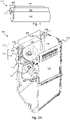
- Figures 2A and 2B respectively show a perspective and cross section of another example of a print agent application assembly 200, in which components in common with Figure 1 are labelled with like numbers.
- first and a second mounting regions 108a, 108b one at either end of the print agent regulator roller 104 and first and second resilient components 110a, 110b, which respectively act on the mounting regions and each of which comprises a sheet metal spring, i.e. a 'leaf spring'.
- the second resilient component 110b which would be obscured by the other components in the view presented, is shown in a dashed box to indicate its position.
- the second mounting region 108b is axially separated from the first mounting region 108a, in this example being separated by the nip forming region 106 of the print agent regulator roller 104.
- Providing a force at each end of the print agent regulator roller 104 may allow a nip pressure to be exerted along the length of the print agent regulator roller 104.
- the mounting regions 108a, 108b of the print agent regulator roller 104 in this example are provided by a central axle, which is of a smaller diameter than the diameter of the nip forming region 106.
- the axle is received at each end by a print agent regulator roller mounting, which in this example is a rotational support, in this example bearing 202 (one of which is shown in cut-through view in Figure 2B , and just one of which is visible in Figure 2A ) and the resilient components 110 are positioned so as to act on the outer race of the bearings 202.
- the resilient components 110 were to act directly on a mounting region 108, there would be relatively high rotational friction and possible heat generation. Having the resilient components 110 act on the outer race of the bearings 202 applies the force to the mounting regions 108 of the print agent regulator roller 104 while allowing relatively low rotational friction via the bearings 202.
- the print agent regulator roller 104 and/or the bearings 202 may be mounted so as to be somewhat moveable in their mountings
- Leaf springs are compact, which means that they can be inserted into the space around the bearings 202 and act directly thereon. In addition, as leaf springs are mechanically simple components, they are robust once installed.
- the resilient components 110 in this example each comprise a first section 204 which spans the width of the print agent regulator roller 104 and a second section 206 which extends into a region of the print agent application assembly 200 outside a region containing the print agent regulator roller 104. As mentioned above, there may be fewer space constraints in such a region.
- the second section 206 has a length which is greater than a length of the first section 204. This may allow for ease of deformation of the resilient components 110 during manufacture of the print agent application assembly 200 as acting on an end of the resilient component 110 which is relatively distant from the mounting region 108 around which the resilient component 110 may be deformed provides a mechanical advantage.
- each of the ends of the resilient components 110 comprise a securing feature in the form of a fold-back portion. This may assist in arranged and securing the resilient components 110 in position.
- resilient components 110 may lack such a securing feature, or comprise an alternative securing feature, such as a cut-out or lateral projection or the like.
- the print agent application assembly 200 further comprises a housing 212 (which is shown in an incomplete form in Figure 2A to expose the interior of the print agent application assembly 200, lacking an end plate and an upper portion).
- the housing 212 comprises retaining features 208, 210, in this example in the form of retaining lugs, for retaining a first and a second end of each of the first and second resilient components 110.
- the print agent regulator roller 104 is positioned between the retaining features 208, 210 for each resilient component 110a, b.
- Providing retaining features 208, 210 integrally with the housing 212 provides for simple manufacturing techniques.
- the housing 212 may for example be formed of at least one injection molded component, for example being formed of a thermosetting, or hard, plastic.
- the retaining features 208, 210 may be integrally formed at the point of molding.
- the retaining features 208, 210 are formed in end plates 214 of the housing 212, the print agent regulator roller 104 being mounted such that the nip forming region 106 is between the end plates 214 and each mounting region 108 is separated from the nip forming region 106 by the end plates 214.
- the end plates 214 may also serve to reduce print agent transfer to the mounting regions 108.
- the retaining features 208, 210 in this example comprise projections from the face of the end plates 214, although in other examples, the retaining features 208 may comprise recesses in the end plates 214 to receive a portion of the resilient components 110, or a combination or recesses and projections, or be formed in some other way. In some examples, retaining features may be provided on a component other than the housing.
- retaining features 208, 210 comprise wall-like projections from the face of the end plates 214, and the fold-back securing features of the resilient components may be formed to engage with the ends of the projections.
- the retaining features 208, 210 may be formed to provide 'hook' like features which retain an end of a resilient component 110 in at least one dimension, and/or may be designed to cooperate with at least one securing feature of the resilient components 110.
- the retaining features 208, 210 (in some examples, in cooperation with any securing features of the resilient components 110) may restrain the ends of the resilient components 110 from movement in a first direction, which may be substantially within the plane of the page/end plate 214 as shown in Figure 2B .
- the retaining features 208, 210 may restrain the ends of the resilient components 110 from movement in a second direction and the second direction may be substantially perpendicular to the page as shown in Figure 2B , for example being a direction which is away from the external face of an end plate 214.
- the end plates 214 themselves, for example a face thereof, may restrain movement of the end of the resilient components 110 in another direction, which may also be substantially perpendicular to the page as shown in Figure 2B .
- Such arrangements may assist in securing a resilient component 100, which may for example be subject to vibration and the like, without requiring fixings, adhesives or the like.
- the resilience of the resilient component 110 and/or the form of a securing feature may secure the resilient components 110 from movement at least one direction, which may be different to the direction of restraint provided by the retaining features 208, 210 and/or by the end plates 214.
- Arranging the resilient components 110 (and/or providing retaining features 208, 210) on the exterior of the housing 212 means that the resilient components 110 may be added after the interior components of the print agent application assembly 200 have been assembled within the housing 212.
- Adding a resilient component 110 for example having the form of a leaf spring at this point is a relatively simple process, as the rollers 102, 104 may be mounted within the housing 212 without working against a biasing force, and then the biasing force is applied to securely mounted roller 104.
- the resilient components 110 may be deflected from a rest position by being formed around the bearings 202 while engaged with one or both retaining features 208, 210.
- the resilient components 110 may follow the form of the mounting regions 108, or a mounting component in which the mounting regions 108 are mounted, of the print agent regulator roller 104, thus occupying little volume beyond that of the print agent regulator roller 104 itself.
- a resilient component 110 may be deflected from a rest position by being formed around the bearings 202 while engaged at a first end with a first retaining feature 208, 210, which holds it in place while the deformation occurs, before being engaged with the second retaining feature 208, 210, which secures it in a deflected position so as to impart a lateral force to a bearing 202.
- the print agent transfer roller 102 comprises an aluminium core coated in a rubber-like (e.g. polyurethane) coating of around 4mm thickness, with a diameter of around 40mm and a length of around 330mm.
- the print agent regulator roller 104 may for example comprise a steel roller which may be coated to reduce corrosion, for example with an electroless nickel plating.
- the print agent regulator roller 104 may have a diameter of around 16mm and a length of around 330mm.
- Each resilient component 110a, 110b is around 45mm in length and exerts a force of around 30 Newton.
- the resilient component 110 in this example comprises spring steel, which provides high yield stress and is unlikely to exhibit plastic deformation during assembly or operation.
- a spring steel comprises a pre-tempered stainless steel 17-7 Condition C which is heat treated to condition CH 900 for higher hardness and yield stress.
- this is purely by way of example, and other dimensions or materials may be seen in other examples.
- the print agent regulator roller 104 may be of a length and stiffness such that any flexibility along its length is relatively minimal so as to allow for a relatively consistent pressure along the nip.
- the print agent regulator roller 104 may be formed or 'crowned' with a profile (for example a parabolic profile) so that it is larger in diameter at the centre than at the ends so as to compensate for any flex and provide a more consistent nip pressure along the length than if such a profile was lacking.
- the end plates 214 may comprise cut out portions and/or strengthening ribs.
- the print agent application assembly 200 may comprise a print agent transfer roller cleaning assembly. In this example this comprises a cleaner roller 216 and a sponge roller 218.
- the cleaner roller 216 rotates to clean the print agent transfer roller 102.
- the sponge roller 218 cleans the cleaner roller 216.
- the cleaning assembly may comprise additional or alternative components.
- the print agent application assembly 200 may comprise additional components, for example electrodes and the like, which are not described in detail herein.
- Figure 3 is an example of a method, which may be a method of manufacturing a print agent application assembly.
- the method comprises, in block 302, mounting a print agent transfer roller in a print agent application assembly housing.
- Block 304 comprises mounting a print agent regulator roller in the print agent application assembly housing so as to form a nip in a nip forming region thereof. The nip may be formed between the print agent regulator roller and the print agent transfer roller.
- Block 306 comprises attaching a first resilient component to the print agent application assembly housing between a first mounting point on a first side of the print agent regulator roller and a second mounting point on a second side of the print agent regulator roller so as to span the diametrical width of the print agent regulator roller and to urge the print agent regulator roller toward the print agent transfer roller by applying pressure thereto outside the nip forming region.
- the print agent transfer roller and the print agent regulator roller may be mounted within a housing, and the first resilient component may be attached to the exterior of the housing.
- attaching the first resilient component may comprise causing the first resilient component to interact with retaining features provided on the housing.
- attaching the first resilient component so as to apply pressure thereto outside the nip forming region comprises applying pressure to the outside of a cylindrical bearing's outer race
- mounting the print agent regulator roller comprises mounting the print agent regulator roller within the cylindrical bearing.
- the method may further comprise mounting the print agent application assembly in a print apparatus (in which case the method may comprise a method of assembling a print apparatus).
- Figure 4 is an example of the method of performing block 306 of Figure 3 .
- the method comprises, in block 402, attaching a first end of the first resilient component to a first mounting point.
- Block 404 comprises deforming the first resilient component around at least part of a print agent regulator roller mounting, which may for example be the mounting portion or may be a receiving element in which the mounting portion is mounted such as a bearing or the like.
- Block 406 comprises attaching a second end of the first resilient component to a second mounting point, wherein the first mounting point is closer to an axis (e.g. the longitudinal axis of the roller) of the print agent regulator roller than the second mounting point.
- the mounting points may have any of the features of the retaining features described in relation to Figure 2A and Figure 2B above.
- the method may benefit from the mechanical advantage is provided when attaching the second end to the more distant second mounting point.
- Block 306 and/or the blocks of Figure 4 may also be carried out in relation to a second resilient component, which may be attached to the housing between a third mounting point on the first side of the print agent regulator roller and a fourth mounting point on the second side of the print agent regulator roller so as to span the diametrical width of the print agent regulator roller and to urge the print agent regulator roller toward the print agent transfer roller, such that the first resilient component acts on a first lateral portion of the print agent regulator roller and the second resilient component acts on a second lateral portion of the print agent regulator roller; wherein the first lateral portion and the second lateral portion are laterally spaced from one another. For example, they may be at either end of the print agent regulator roller, and/or may be either side of the nip forming region.
- the method of Figure 3 and/or Figure 4 may be a method of manufacturing a print agent application assembly as described in relation to Figure 1 or Figure 2 above.
- Figure 5 shows an example of a print apparatus 500 comprising a print agent application assembly 502 and a photoconductive surface 504.
- the print agent application assembly 502 is to transfer a layer of print agent to the photoconductive surface 504, and the thickness of the layer of print agent is controlled by a nip pressure formed between rollers 506, 508 in the print agent application assembly 502, the pressure being controlled by a first and second sheet metal spring 510 (just one of which is visible in Figure 5 ) acting on a respective first and second roller mounting 512 (just one of which is visible in Figure 5 ) to provide the nip pressure.
- the first and second roller mountings 512 may for example be a mounting portion of a roller or may be a receiving element in which the mounting portion is mounted such as a rotational support such as a bearing or the like.
- the print agent application assembly 502 may be a print agent application assembly as described in relation to Figure 1 or Figure 2 above.
- Such a print apparatus 500 may comprise additional components, for example media or image transfer apparatus, additional print agent application assembly 502, heaters and the like.
- additional print agent application assembly 502 for example media or image transfer apparatus, additional print agent application assembly 502, heaters and the like.
- the print apparatus 500 is an LEP.
Landscapes
- Physics & Mathematics (AREA)
- General Physics & Mathematics (AREA)
- Ink Jet (AREA)
- Ink Jet Recording Methods And Recording Media Thereof (AREA)
- Electrostatic Charge, Transfer And Separation In Electrography (AREA)
- Electrophotography Configuration And Component (AREA)
Description
- Printing systems such as liquid electro photographic printers may include at least one print agent application assembly. Print agent application assemblies may form images on a photoconductive member using liquid toner, and the like.
-
US5737666 discloses toning apparatus in which a squeegee roller is urged against a toning roller by a leaf spring having a compressible pad to avoid direct contact between the spring and the squeegee roller.US 2004/000 9018 discloses a toner layer forming rollerwhich is urged against a developer roller by means of springs.US 2014/025 3652 discloses a pressure roller which forms a nip with an application roller such that a web may be guided therebetween. - The scope of the invention is defined by the appended claims. Further embodiments of the invention are defined by the dependent claims. Any embodiments which do not fall within the scope of the appended set of claims are to be interpreted as example embodiments of background information, useful only for understanding the invention.
- For a more complete understanding, reference is now made to the following description taken in conjunction with the accompanying drawings in which:
-
Figure 1 shows an example of a print agent application assembly; -
Figures 2A and2B show another example of a print agent application assembly; -
Figure 3 is a flowchart of an example method of forming a print agent application assembly; -
Figure 4 is a flowchart of an example method of placing a resilient member in a print agent application assembly; and -
Figure 5 shows an example of a print apparatus. - Printing systems such as liquid electro photographic (LEP) printers include print agent application assemblies, which may be known as binary ink developer (BID) assemblies. The print agent application assemblies may utilize liquid toner (hereinafter print agent) to form images.
- In such apparatus, a roller, which may be referred to as a print agent transfer roller, or a developer roller, bearing a layer of print agent is urged against a photoconductive surface (for example, a photoconductive imaging plate, which may be wrapped to form the surface of a drum). The photoconductive surface carries a charge pattern, which provides a latent image corresponding to the image to be printed. Due to the relative charges of the print agent, the photoconductive surface and the print agent transfer roller, print agent is transferred from the print agent transfer roller to the photoconductive surface to form the image to be printed. In order to regulate the thickness of the layer of ink on the print agent transfer roller, a print agent regulator roller, which may be referred to as a "squeegee" roller, may be urged against the print agent transfer roller to control the thickness of an ink layer which is transferred to the photoconductive surface.
-
Figure 1 shows an example of a printagent application assembly 100 comprising a printagent transfer roller 102 and a printagent regulator roller 104. The printagent transfer roller 102 receives print agent and transfer at least a portion of the print agent to a photoconductive surface. The printagent regulator roller 104 regulates a film thickness of print agent on the printagent transfer roller 102. The printagent regulator roller 104 comprises anip forming region 106 and afirst mounting region 108. The 'nip' is formed between the printagent transfer roller 102 and printagent regulator roller 104 and represents the portion of therollers mounting region 108 extends beyond the nip-formingregion 106 and may comprise any mounting, for example an axle to be received in rotational support such as a bearing or the like. In some examples, theresilient component 110 may act on themounting region 108 directly. In some examples, theresilient component 110 may act on themounting region 108 via a print agent regulator roller mounting, such as a bearing or the like. Although in this example, the printagent transfer roller 102 and printagent regulator roller 104 are the same length, in another example, the printagent transfer roller 102 may be approximately the length of thenip forming region 106. - The print
agent application assembly 100 further comprises a firstresilient component 110. The firstresilient component 110 spans a diametrical width of the printagent regulator roller 104 and acts on the printagent regulator roller 104 outside thenip forming region 106 to impart a lateral force to the mounting region 108 (which may be lateral to the longitudinal axis of the print agent regulator roller 104), the lateral force urging the printagent regulator roller 104 towards the printagent transfer roller 102. - By providing a lateral force to the
mounting region 108, rather than thenip forming region 106, there is no interference between the firstresilient component 110 and any print agent which is transferred to the printagent regulator roller 104 from the printagent transfer roller 102 is prevented. Moreover, the use of aresilient component 110 which spans the diametrical width of the printagent regulator roller 104 means that force may be applied using an elongate resilient component. As is further set out below, such aresilient component 110 may be relatively simple, comprising a sheet metal member (e.g. a leaf spring), and may extend to a mounting point which is spaced from therollers rollers resilient component 110 to extend to a region in which such constraints may be lessened. In some examples, theresilient member 110 may curve around at least a portion of the circumference of the mounting region 108 (or curve around a print agent regulator roller mounting, for example a rotational support such as a bearing or the like, in which themounting region 108 is received), or otherwise be deflected from a rest position and/or shape by themounting region 108 and/or receiving portion, which allows it apply force to themounting region 108 while having a compact form. -
Figures 2A and2B respectively show a perspective and cross section of another example of a printagent application assembly 200, in which components in common withFigure 1 are labelled with like numbers. - In the perspective view of
Figure 2A , one of two end plates 214 (shown in greater detail inFigure 2B ) has been removed from one side to expose the interior of printagent application assembly 200. - As can be seen from
Figure 2A , in this example, there is a first and a second mounting regions 108a, 108b, one at either end of the printagent regulator roller 104 and first and secondresilient components resilient component 110b, which would be obscured by the other components in the view presented, is shown in a dashed box to indicate its position. The second mounting region 108b is axially separated from the first mounting region 108a, in this example being separated by thenip forming region 106 of the printagent regulator roller 104. - Providing a force at each end of the print
agent regulator roller 104 may allow a nip pressure to be exerted along the length of the printagent regulator roller 104. The mounting regions 108a, 108b of the printagent regulator roller 104 in this example are provided by a central axle, which is of a smaller diameter than the diameter of thenip forming region 106. The axle is received at each end by a print agent regulator roller mounting, which in this example is a rotational support, in this example bearing 202 (one of which is shown in cut-through view inFigure 2B , and just one of which is visible inFigure 2A ) and theresilient components 110 are positioned so as to act on the outer race of thebearings 202. It may be noted that, if theresilient components 110 were to act directly on amounting region 108, there would be relatively high rotational friction and possible heat generation. Having theresilient components 110 act on the outer race of thebearings 202 applies the force to themounting regions 108 of the printagent regulator roller 104 while allowing relatively low rotational friction via thebearings 202. In this example, the printagent regulator roller 104 and/or thebearings 202 may be mounted so as to be somewhat moveable in their mountings - Leaf springs are compact, which means that they can be inserted into the space around the
bearings 202 and act directly thereon. In addition, as leaf springs are mechanically simple components, they are robust once installed. - The
resilient components 110 in this example each comprise afirst section 204 which spans the width of the printagent regulator roller 104 and asecond section 206 which extends into a region of the printagent application assembly 200 outside a region containing the printagent regulator roller 104. As mentioned above, there may be fewer space constraints in such a region. Thesecond section 206 has a length which is greater than a length of thefirst section 204. This may allow for ease of deformation of theresilient components 110 during manufacture of the printagent application assembly 200 as acting on an end of theresilient component 110 which is relatively distant from themounting region 108 around which theresilient component 110 may be deformed provides a mechanical advantage. In this example, it may be noted that each of the ends of theresilient components 110 comprise a securing feature in the form of a fold-back portion. This may assist in arranged and securing theresilient components 110 in position. In other examples,resilient components 110 may lack such a securing feature, or comprise an alternative securing feature, such as a cut-out or lateral projection or the like. - The print
agent application assembly 200 further comprises a housing 212 (which is shown in an incomplete form inFigure 2A to expose the interior of the printagent application assembly 200, lacking an end plate and an upper portion). As is shown inFigure 2B , thehousing 212 comprises retainingfeatures resilient components 110. The printagent regulator roller 104 is positioned between theretaining features resilient component 110a, b. Providing retaining features 208, 210 integrally with thehousing 212 provides for simple manufacturing techniques. Thehousing 212 may for example be formed of at least one injection molded component, for example being formed of a thermosetting, or hard, plastic. The retaining features 208, 210 may be integrally formed at the point of molding. - In this example, the retaining features 208, 210 are formed in
end plates 214 of thehousing 212, the printagent regulator roller 104 being mounted such that thenip forming region 106 is between theend plates 214 and each mountingregion 108 is separated from thenip forming region 106 by theend plates 214. Theend plates 214 may also serve to reduce print agent transfer to the mountingregions 108. The retaining features 208, 210 in this example comprise projections from the face of theend plates 214, although in other examples, the retaining features 208 may comprise recesses in theend plates 214 to receive a portion of theresilient components 110, or a combination or recesses and projections, or be formed in some other way. In some examples, retaining features may be provided on a component other than the housing. - In particular, in this example, retaining
features end plates 214, and the fold-back securing features of the resilient components may be formed to engage with the ends of the projections. The retaining features 208, 210 may be formed to provide 'hook' like features which retain an end of aresilient component 110 in at least one dimension, and/or may be designed to cooperate with at least one securing feature of theresilient components 110. In some examples, the retaining features 208, 210 (in some examples, in cooperation with any securing features of the resilient components 110) may restrain the ends of theresilient components 110 from movement in a first direction, which may be substantially within the plane of the page/end plate 214 as shown inFigure 2B . In some examples, the retaining features 208, 210 (in some examples, in cooperation with any securing features of the resilient components 110) may restrain the ends of theresilient components 110 from movement in a second direction and the second direction may be substantially perpendicular to the page as shown inFigure 2B , for example being a direction which is away from the external face of anend plate 214. Theend plates 214 themselves, for example a face thereof, may restrain movement of the end of theresilient components 110 in another direction, which may also be substantially perpendicular to the page as shown inFigure 2B . Such arrangements may assist in securing aresilient component 100, which may for example be subject to vibration and the like, without requiring fixings, adhesives or the like. The resilience of theresilient component 110 and/or the form of a securing feature may secure theresilient components 110 from movement at least one direction, which may be different to the direction of restraint provided by the retaining features 208, 210 and/or by theend plates 214. - Arranging the resilient components 110 (and/or providing retaining features 208, 210) on the exterior of the
housing 212 means that theresilient components 110 may be added after the interior components of the printagent application assembly 200 have been assembled within thehousing 212. Adding aresilient component 110 for example having the form of a leaf spring at this point is a relatively simple process, as therollers housing 212 without working against a biasing force, and then the biasing force is applied to securely mountedroller 104. - The
resilient components 110 may be deflected from a rest position by being formed around thebearings 202 while engaged with one or both retainingfeatures resilient components 110 may follow the form of the mountingregions 108, or a mounting component in which the mountingregions 108 are mounted, of the printagent regulator roller 104, thus occupying little volume beyond that of the printagent regulator roller 104 itself. In one example, aresilient component 110 may be deflected from a rest position by being formed around thebearings 202 while engaged at a first end with afirst retaining feature second retaining feature bearing 202. - In this example, the print
agent transfer roller 102 comprises an aluminium core coated in a rubber-like (e.g. polyurethane) coating of around 4mm thickness, with a diameter of around 40mm and a length of around 330mm. The printagent regulator roller 104 may for example comprise a steel roller which may be coated to reduce corrosion, for example with an electroless nickel plating. The printagent regulator roller 104 may have a diameter of around 16mm and a length of around 330mm. Eachresilient component resilient component 110 in this example comprises spring steel, which provides high yield stress and is unlikely to exhibit plastic deformation during assembly or operation. In an example, a spring steel comprises a pre-tempered stainless steel 17-7 Condition C which is heat treated to condition CH 900 for higher hardness and yield stress. However, this is purely by way of example, and other dimensions or materials may be seen in other examples. - In some examples, the print
agent regulator roller 104 may be of a length and stiffness such that any flexibility along its length is relatively minimal so as to allow for a relatively consistent pressure along the nip. In other examples, the printagent regulator roller 104 may be formed or 'crowned' with a profile (for example a parabolic profile) so that it is larger in diameter at the centre than at the ends so as to compensate for any flex and provide a more consistent nip pressure along the length than if such a profile was lacking. - As is shown in
Figure 2B , theend plates 214 may comprise cut out portions and/or strengthening ribs. As is best shown fromFigure 2A , the printagent application assembly 200 may comprise a print agent transfer roller cleaning assembly. In this example this comprises acleaner roller 216 and asponge roller 218. Thecleaner roller 216 rotates to clean the printagent transfer roller 102. Thesponge roller 218 cleans thecleaner roller 216. In other examples, the cleaning assembly may comprise additional or alternative components. The printagent application assembly 200 may comprise additional components, for example electrodes and the like, which are not described in detail herein. -
Figure 3 is an example of a method, which may be a method of manufacturing a print agent application assembly. The method comprises, inblock 302, mounting a print agent transfer roller in a print agent application assembly housing.Block 304 comprises mounting a print agent regulator roller in the print agent application assembly housing so as to form a nip in a nip forming region thereof. The nip may be formed between the print agent regulator roller and the print agent transfer roller.Block 306 comprises attaching a first resilient component to the print agent application assembly housing between a first mounting point on a first side of the print agent regulator roller and a second mounting point on a second side of the print agent regulator roller so as to span the diametrical width of the print agent regulator roller and to urge the print agent regulator roller toward the print agent transfer roller by applying pressure thereto outside the nip forming region. - In some examples, the print agent transfer roller and the print agent regulator roller may be mounted within a housing, and the first resilient component may be attached to the exterior of the housing. In some examples, attaching the first resilient component may comprise causing the first resilient component to interact with retaining features provided on the housing. In some examples, attaching the first resilient component so as to apply pressure thereto outside the nip forming region comprises applying pressure to the outside of a cylindrical bearing's outer race, and mounting the print agent regulator roller comprises mounting the print agent regulator roller within the cylindrical bearing. In some examples, the method may further comprise mounting the print agent application assembly in a print apparatus (in which case the method may comprise a method of assembling a print apparatus).
-
Figure 4 is an example of the method of performingblock 306 ofFigure 3 . The method comprises, inblock 402, attaching a first end of the first resilient component to a first mounting point.Block 404 comprises deforming the first resilient component around at least part of a print agent regulator roller mounting, which may for example be the mounting portion or may be a receiving element in which the mounting portion is mounted such as a bearing or the like.Block 406 comprises attaching a second end of the first resilient component to a second mounting point, wherein the first mounting point is closer to an axis (e.g. the longitudinal axis of the roller) of the print agent regulator roller than the second mounting point. The mounting points may have any of the features of the retaining features described in relation toFigure 2A andFigure 2B above. - By attaching the first end to the first mounting point which is closer to an axis of the print agent regulator roller than the second mounting point, the method may benefit from the mechanical advantage is provided when attaching the second end to the more distant second mounting point.
-
Block 306 and/or the blocks ofFigure 4 may also be carried out in relation to a second resilient component, which may be attached to the housing between a third mounting point on the first side of the print agent regulator roller and a fourth mounting point on the second side of the print agent regulator roller so as to span the diametrical width of the print agent regulator roller and to urge the print agent regulator roller toward the print agent transfer roller, such that the first resilient component acts on a first lateral portion of the print agent regulator roller and the second resilient component acts on a second lateral portion of the print agent regulator roller; wherein the first lateral portion and the second lateral portion are laterally spaced from one another. For example, they may be at either end of the print agent regulator roller, and/or may be either side of the nip forming region. - In some examples, the method of
Figure 3 and/orFigure 4 may be a method of manufacturing a print agent application assembly as described in relation toFigure 1 orFigure 2 above. -
Figure 5 shows an example of aprint apparatus 500 comprising a printagent application assembly 502 and aphotoconductive surface 504. The printagent application assembly 502 is to transfer a layer of print agent to thephotoconductive surface 504, and the thickness of the layer of print agent is controlled by a nip pressure formed betweenrollers agent application assembly 502, the pressure being controlled by a first and second sheet metal spring 510 (just one of which is visible inFigure 5 ) acting on a respective first and second roller mounting 512 (just one of which is visible inFigure 5 ) to provide the nip pressure. The first andsecond roller mountings 512 may for example be a mounting portion of a roller or may be a receiving element in which the mounting portion is mounted such as a rotational support such as a bearing or the like. For example, the printagent application assembly 502 may be a print agent application assembly as described in relation toFigure 1 orFigure 2 above. - Such a
print apparatus 500 may comprise additional components, for example media or image transfer apparatus, additional printagent application assembly 502, heaters and the like. In some examples theprint apparatus 500 is an LEP. - While the method, apparatus and related aspects have been described with reference to certain examples, various modifications, changes, omissions, and substitutions can be made. It is intended, therefore, that the method, apparatus and related aspects be limited by the scope of the following claims . It should be noted that the above-mentioned examples illustrate rather than limit what is described herein, and that those skilled in the art will be able to design many alternative implementations without departing from the scope of the appended claims. Features described in relation to one example may be combined with features of another example.
- The word "comprising" does not exclude the presence of elements other than those listed in a claim, "a" or "an" does not exclude a plurality, and a single processor or other unit may fulfil the functions of several units recited in the claims.
- The features of any dependent claim may be combined with the features of any of the independent claims or other dependent claims.
Claims (14)
- A print agent application assembly (100, 200, 502) comprising:a print agent transfer roller (102) to receive print agent and transfer a portion of the print agent to a photoconductive surface (504);a print agent regulator roller (104) to regulate a film thickness of print agent on the print agent transfer roller (102), the print agent regulator roller (104) comprising a nip forming region (106) and a mounting region (108); and characterised by:
a resilient component comprising a sheet metal spring (110, 510) , which spans a diametrical width of the print agent regulator roller (104) and acts on the print agent regulator roller (104) outside the nip forming region (106) to impart a lateral force to the mounting region (108), the lateral force urging the print agent regulator roller (104) towards the print agent transfer roller (102). - A print agent application assembly (100, 200, 502) according to claim 1 in which the sheet metal spring (110, 510) comprises a first section which spans the diametrical width of the print agent regulator roller (104) and a second section which extends into a region of the print agent application assembly (100, 200, 502) outside a region containing print agent regulator roller (104).
- A print agent application assembly (100, 200, 502) according to claim 2 in which the second section has a length which is greater than a length of the first section.
- A print agent application assembly (100, 200, 502) according to claim 1 further comprising a housing (212), the housing (212) comprising retaining features (208, 210) for retaining a first end and a second end of the sheet metal spring (110, 510).
- A print agent application assembly (100, 200, 502) according to claim 4 in which the housing (212) comprises end plates (214) and the print agent regulator roller (104) is mounted such that the nip forming region (106) is between the end plates (214) and each mounting region (108) is separated from the nip forming region (106) by the end plates (214), wherein the retaining features (208, 210) are formed on the end plates (214).
- A print agent application assembly (100, 200, 502) according to claim 1 further comprising a housing (212), wherein the nip forming region (106) of the print agent regulator roller (104) is provided inside the housing (212) and the sheet metal spring (110, 110a, 510) and at least part of the first mounting region (108) are provided outside the housing (212).
- A print agent application assembly (100, 200, 502) according to claim 1 wherein the print agent regulator roller (104) comprises a second mounting region (108a, 108b) which is axially separated from the first mounting region (108), the print agent application assembly (100, 200, 502) further comprising a second sheet metal spring (110, 510), the second sheet metal spring (110, 510) acting on the second mounting region (108).
- A print agent application assembly (100, 200, 502) according to claim 1 further comprising a rotational support, wherein the mounting portion of the print agent regulator roller (104) is mounted within a rotational support and the first resilient component (110, 110a) is positioned so as to act on the exterior of the rotational support.
- A print agent application assembly (100, 200, 502) according to claim 1 wherein the lateral force is approximately 30 Newton.
- A method comprising:mounting a print agent transfer roller (102) in a print agent application assembly housing (212);mounting a print agent regulator roller (104) in the print agent application assembly housing (212) so as to form a nip in a nip forming region (106) thereof; the method being characterised by:
attaching a sheet metal spring (110, 510)to the print agent application assembly housing (212) between a first mounting point on a first side of the print agent regulator roller (104) and a second mounting point on a second side of the print agent regulator roller (104) so as to span a diametrical width of the print agent regulator roller (104) and to urge the print agent regulator roller (104) toward the print agent transfer roller (102) by applying pressure thereto outside the nip forming region (106). - A method according to claim 10, wherein mounting the resilient component (110, 110a) comprises deforming the sheet metal spring (110, 510) around at least part of a print agent regulator roller mounting.
- A method according to claim 11, wherein mounting the sheet metal spring (110, 510) comprises mounting the sheet metal spring (110, 510) between the first mounting point and the second mounting point, wherein the first mounting point is closer to an axis of the print agent regulator roller (104) than the second mounting point.
- A method according to claim 12 further comprising attaching a second sheet metal spring (110, 510) between a third mounting point on the first side of the print agent regulator roller (104) and a fourth mounting point on the second side of the print agent regulator roller (104) so as to span the diametrical width of the print agent regulator roller (104) and to urge the print agent regulator roller (104) toward the print agent transfer roller (102), such that the first sheet metal spring (110, 510) acts on a first lateral portion of the print agent regulator roller (104) and the second sheet metal spring (110, 510) acts on a second lateral portion of the print agent regulator roller (104); wherein the first lateral portion and the second lateral portion are laterally separated from one another by the nip forming region (106).
- A print apparatus (500) comprising a print agent application assembly (100, 200, 502) according to claim 1 and a photoconductive surface (504), wherein the print agent application assembly (100, 200, 502) is to transfer a layer of print agent to the photoconductive surface (504), wherein a thickness of the layer of print agent is controlled by a nip pressure formed between rollers in the print agent application assembly (100, 200, 502) in the nip forming region, the nip pressure being controlled by a first and second sheet metal spring (510) acting respectively on first and second roller mountings (512) to provide the nip pressure.
Applications Claiming Priority (1)
| Application Number | Priority Date | Filing Date | Title |
|---|---|---|---|
| PCT/US2017/019742 WO2018156169A1 (en) | 2017-02-27 | 2017-02-27 | Print agent application assemblies |
Publications (3)
| Publication Number | Publication Date |
|---|---|
| EP3585621A1 EP3585621A1 (en) | 2020-01-01 |
| EP3585621A4 EP3585621A4 (en) | 2020-10-28 |
| EP3585621B1 true EP3585621B1 (en) | 2022-06-08 |
Family
ID=63253955
Family Applications (1)
| Application Number | Title | Priority Date | Filing Date |
|---|---|---|---|
| EP17897381.4A Active EP3585621B1 (en) | 2017-02-27 | 2017-02-27 | Print agent application assemblies |
Country Status (4)
| Country | Link |
|---|---|
| US (1) | US10877402B2 (en) |
| EP (1) | EP3585621B1 (en) |
| CN (1) | CN110225828B (en) |
| WO (1) | WO2018156169A1 (en) |
Family Cites Families (17)
| Publication number | Priority date | Publication date | Assignee | Title |
|---|---|---|---|---|
| GB934921A (en) | 1962-05-12 | 1963-08-21 | Siemens Ag | Improvements in or relating to apparatus for inking rotary type drums |
| US4082447A (en) | 1977-02-03 | 1978-04-04 | Cineffects Color Laboratory Inc. | Wet gate embodied in a photographic strip film printer |
| EP0764891B1 (en) * | 1991-07-09 | 2001-07-18 | Indigo N.V. | Liquid toner developer cartridge |
| IL107217A (en) * | 1993-10-08 | 2004-05-12 | Hewlett Packard Indigo Bv | Development control system |
| US5329850A (en) | 1992-07-10 | 1994-07-19 | Eduardo Duarte | Metering roller for a lithographic printing press |
| EP0678202B1 (en) * | 1993-01-11 | 1998-04-08 | Indigo N.V. | Latent image development apparatus |
| JP3334963B2 (en) * | 1993-02-01 | 2002-10-15 | キヤノン株式会社 | Coupling method for reconnecting a cylindrical member and an engagement member |
| US6108513A (en) | 1995-04-03 | 2000-08-22 | Indigo N.V. | Double sided imaging |
| KR200172924Y1 (en) | 1997-08-27 | 2000-03-02 | 윤종용 | Developer roller cleaning apparatus for a liquid electrographic imaging system |
| NL1011992C2 (en) | 1999-05-07 | 2000-11-09 | Stork Brabant Bv | Squeegee. |
| WO2001032432A1 (en) | 1999-11-04 | 2001-05-10 | Matsushita Electric Industrial Co., Ltd. | Image forming device |
| US6735408B2 (en) | 2001-03-21 | 2004-05-11 | Ricoh Company, Ltd. | Image forming apparatus with adjustable removal and developing nips |
| KR100433538B1 (en) | 2002-02-06 | 2004-05-31 | 삼성전자주식회사 | Apparatus for forming color image using electrophotography |
| DE60310167T2 (en) | 2002-07-12 | 2007-09-20 | Oki Data Corp. | Developer and electrophotographic device |
| US9223253B2 (en) * | 2012-01-20 | 2015-12-29 | Hewlett-Packard Indigo B.V. | Electrostatic printing |
| DE102013100843B3 (en) | 2013-01-29 | 2014-02-27 | Océ Printing Systems GmbH & Co. KG | High-speed digital printer i.e. roll-roll-printer, for printing e.g. web-like recording medium, has dosing unit providing spring unit, which exerts pressure force that is adjustable in direction of developer roller, on dosing roller |
| JP6287068B2 (en) | 2013-03-11 | 2018-03-07 | 株式会社リコー | Treatment liquid application apparatus for ink jet printer and image forming system provided with the same |
-
2017
- 2017-02-27 CN CN201780084818.8A patent/CN110225828B/en active Active
- 2017-02-27 WO PCT/US2017/019742 patent/WO2018156169A1/en not_active Ceased
- 2017-02-27 US US16/472,975 patent/US10877402B2/en active Active
- 2017-02-27 EP EP17897381.4A patent/EP3585621B1/en active Active
Also Published As
| Publication number | Publication date |
|---|---|
| US20200192248A1 (en) | 2020-06-18 |
| EP3585621A1 (en) | 2020-01-01 |
| US10877402B2 (en) | 2020-12-29 |
| CN110225828B (en) | 2021-08-10 |
| EP3585621A4 (en) | 2020-10-28 |
| WO2018156169A1 (en) | 2018-08-30 |
| CN110225828A (en) | 2019-09-10 |
Similar Documents
| Publication | Publication Date | Title |
|---|---|---|
| EP3163378B1 (en) | Fusing device and image forming apparatus having the same | |
| JP2012173346A (en) | Electric conduction mechanism for rotor, image carrier unit, process cartridge, image forming apparatus, and electric conduction method for image carrier unit | |
| JP5967970B2 (en) | Cleaning device, process cartridge, and image forming apparatus | |
| US20190018363A1 (en) | Cartridge and image forming apparatus | |
| JP4378049B2 (en) | Image forming apparatus | |
| EP1333339B1 (en) | Stripper fingers and associated mounts for a xerographic fusing apparatus | |
| US10877402B2 (en) | Print agent application assemblies | |
| US20180299826A1 (en) | Rotatable member, process cartridge and image forming apparatus | |
| US9527689B2 (en) | Image forming apparatus including re-conveying unit | |
| CN103765326B (en) | Cleaning parts, cleaning devices, process cartridges and image forming equipment | |
| US20170285555A1 (en) | Lubricant supply device and image forming device | |
| CN119493353A (en) | Image forming device | |
| JP4217697B2 (en) | Electrophotographic process cartridge | |
| JP6700839B2 (en) | Cartridge and image forming apparatus | |
| JP2001356628A (en) | Roller and its manufacturing method | |
| KR20080070166A (en) | Image forming apparatus and cleaning unit therefor | |
| JP4687161B2 (en) | Fixing device | |
| JP3096997B2 (en) | Image forming device | |
| JP7578049B2 (en) | Image forming device | |
| WO2002093266A2 (en) | Contact development system reference structure | |
| JP2012022111A (en) | Developing device, cleaner, process cartridge, and image forming apparatus | |
| JPH08202145A (en) | Developing device | |
| JP5533469B2 (en) | Lubricant coating apparatus, process cartridge, intermediate cleaning unit, and image forming apparatus | |
| KR200332708Y1 (en) | Apparatus for pressurizing toner carry member of processor cartridge | |
| JPH08202225A (en) | Roller cleaning device |
Legal Events
| Date | Code | Title | Description |
|---|---|---|---|
| STAA | Information on the status of an ep patent application or granted ep patent |
Free format text: STATUS: THE INTERNATIONAL PUBLICATION HAS BEEN MADE |
|
| PUAI | Public reference made under article 153(3) epc to a published international application that has entered the european phase |
Free format text: ORIGINAL CODE: 0009012 |
|
| STAA | Information on the status of an ep patent application or granted ep patent |
Free format text: STATUS: REQUEST FOR EXAMINATION WAS MADE |
|
| 17P | Request for examination filed |
Effective date: 20190718 |
|
| AK | Designated contracting states |
Kind code of ref document: A1 Designated state(s): AL AT BE BG CH CY CZ DE DK EE ES FI FR GB GR HR HU IE IS IT LI LT LU LV MC MK MT NL NO PL PT RO RS SE SI SK SM TR |
|
| AX | Request for extension of the european patent |
Extension state: BA ME |
|
| DAV | Request for validation of the european patent (deleted) | ||
| DAX | Request for extension of the european patent (deleted) | ||
| A4 | Supplementary search report drawn up and despatched |
Effective date: 20200930 |
|
| RIC1 | Information provided on ipc code assigned before grant |
Ipc: G03G 15/08 20060101ALN20200924BHEP Ipc: G03G 15/10 20060101AFI20200924BHEP Ipc: G03G 15/11 20060101ALI20200924BHEP |
|
| REG | Reference to a national code |
Ref country code: DE Ref legal event code: R079 Ref document number: 602017058419 Country of ref document: DE Free format text: PREVIOUS MAIN CLASS: B41J0002410000 Ipc: G03G0015100000 |
|
| GRAP | Despatch of communication of intention to grant a patent |
Free format text: ORIGINAL CODE: EPIDOSNIGR1 |
|
| STAA | Information on the status of an ep patent application or granted ep patent |
Free format text: STATUS: GRANT OF PATENT IS INTENDED |
|
| RIC1 | Information provided on ipc code assigned before grant |
Ipc: G03G 15/08 20060101ALN20220112BHEP Ipc: G03G 15/11 20060101ALI20220112BHEP Ipc: G03G 15/10 20060101AFI20220112BHEP |
|
| RIC1 | Information provided on ipc code assigned before grant |
Ipc: G03G 15/08 20060101ALN20220201BHEP Ipc: G03G 15/11 20060101ALI20220201BHEP Ipc: G03G 15/10 20060101AFI20220201BHEP |
|
| INTG | Intention to grant announced |
Effective date: 20220214 |
|
| GRAS | Grant fee paid |
Free format text: ORIGINAL CODE: EPIDOSNIGR3 |
|
| GRAA | (expected) grant |
Free format text: ORIGINAL CODE: 0009210 |
|
| STAA | Information on the status of an ep patent application or granted ep patent |
Free format text: STATUS: THE PATENT HAS BEEN GRANTED |
|
| AK | Designated contracting states |
Kind code of ref document: B1 Designated state(s): AL AT BE BG CH CY CZ DE DK EE ES FI FR GB GR HR HU IE IS IT LI LT LU LV MC MK MT NL NO PL PT RO RS SE SI SK SM TR |
|
| REG | Reference to a national code |
Ref country code: AT Ref legal event code: REF Ref document number: 1497337 Country of ref document: AT Kind code of ref document: T Effective date: 20220615 Ref country code: CH Ref legal event code: EP |
|
| REG | Reference to a national code |
Ref country code: DE Ref legal event code: R096 Ref document number: 602017058419 Country of ref document: DE |
|
| REG | Reference to a national code |
Ref country code: IE Ref legal event code: FG4D |
|
| REG | Reference to a national code |
Ref country code: LT Ref legal event code: MG9D |
|
| REG | Reference to a national code |
Ref country code: NL Ref legal event code: MP Effective date: 20220608 |
|
| PG25 | Lapsed in a contracting state [announced via postgrant information from national office to epo] |
Ref country code: SE Free format text: LAPSE BECAUSE OF FAILURE TO SUBMIT A TRANSLATION OF THE DESCRIPTION OR TO PAY THE FEE WITHIN THE PRESCRIBED TIME-LIMIT Effective date: 20220608 Ref country code: NO Free format text: LAPSE BECAUSE OF FAILURE TO SUBMIT A TRANSLATION OF THE DESCRIPTION OR TO PAY THE FEE WITHIN THE PRESCRIBED TIME-LIMIT Effective date: 20220908 Ref country code: LT Free format text: LAPSE BECAUSE OF FAILURE TO SUBMIT A TRANSLATION OF THE DESCRIPTION OR TO PAY THE FEE WITHIN THE PRESCRIBED TIME-LIMIT Effective date: 20220608 Ref country code: HR Free format text: LAPSE BECAUSE OF FAILURE TO SUBMIT A TRANSLATION OF THE DESCRIPTION OR TO PAY THE FEE WITHIN THE PRESCRIBED TIME-LIMIT Effective date: 20220608 Ref country code: GR Free format text: LAPSE BECAUSE OF FAILURE TO SUBMIT A TRANSLATION OF THE DESCRIPTION OR TO PAY THE FEE WITHIN THE PRESCRIBED TIME-LIMIT Effective date: 20220909 Ref country code: FI Free format text: LAPSE BECAUSE OF FAILURE TO SUBMIT A TRANSLATION OF THE DESCRIPTION OR TO PAY THE FEE WITHIN THE PRESCRIBED TIME-LIMIT Effective date: 20220608 Ref country code: ES Free format text: LAPSE BECAUSE OF FAILURE TO SUBMIT A TRANSLATION OF THE DESCRIPTION OR TO PAY THE FEE WITHIN THE PRESCRIBED TIME-LIMIT Effective date: 20220608 Ref country code: BG Free format text: LAPSE BECAUSE OF FAILURE TO SUBMIT A TRANSLATION OF THE DESCRIPTION OR TO PAY THE FEE WITHIN THE PRESCRIBED TIME-LIMIT Effective date: 20220908 |
|
| REG | Reference to a national code |
Ref country code: AT Ref legal event code: MK05 Ref document number: 1497337 Country of ref document: AT Kind code of ref document: T Effective date: 20220608 |
|
| PG25 | Lapsed in a contracting state [announced via postgrant information from national office to epo] |
Ref country code: RS Free format text: LAPSE BECAUSE OF FAILURE TO SUBMIT A TRANSLATION OF THE DESCRIPTION OR TO PAY THE FEE WITHIN THE PRESCRIBED TIME-LIMIT Effective date: 20220608 Ref country code: LV Free format text: LAPSE BECAUSE OF FAILURE TO SUBMIT A TRANSLATION OF THE DESCRIPTION OR TO PAY THE FEE WITHIN THE PRESCRIBED TIME-LIMIT Effective date: 20220608 |
|
| PG25 | Lapsed in a contracting state [announced via postgrant information from national office to epo] |
Ref country code: NL Free format text: LAPSE BECAUSE OF FAILURE TO SUBMIT A TRANSLATION OF THE DESCRIPTION OR TO PAY THE FEE WITHIN THE PRESCRIBED TIME-LIMIT Effective date: 20220608 |
|
| PG25 | Lapsed in a contracting state [announced via postgrant information from national office to epo] |
Ref country code: SM Free format text: LAPSE BECAUSE OF FAILURE TO SUBMIT A TRANSLATION OF THE DESCRIPTION OR TO PAY THE FEE WITHIN THE PRESCRIBED TIME-LIMIT Effective date: 20220608 Ref country code: SK Free format text: LAPSE BECAUSE OF FAILURE TO SUBMIT A TRANSLATION OF THE DESCRIPTION OR TO PAY THE FEE WITHIN THE PRESCRIBED TIME-LIMIT Effective date: 20220608 Ref country code: RO Free format text: LAPSE BECAUSE OF FAILURE TO SUBMIT A TRANSLATION OF THE DESCRIPTION OR TO PAY THE FEE WITHIN THE PRESCRIBED TIME-LIMIT Effective date: 20220608 Ref country code: PT Free format text: LAPSE BECAUSE OF FAILURE TO SUBMIT A TRANSLATION OF THE DESCRIPTION OR TO PAY THE FEE WITHIN THE PRESCRIBED TIME-LIMIT Effective date: 20221010 Ref country code: EE Free format text: LAPSE BECAUSE OF FAILURE TO SUBMIT A TRANSLATION OF THE DESCRIPTION OR TO PAY THE FEE WITHIN THE PRESCRIBED TIME-LIMIT Effective date: 20220608 Ref country code: CZ Free format text: LAPSE BECAUSE OF FAILURE TO SUBMIT A TRANSLATION OF THE DESCRIPTION OR TO PAY THE FEE WITHIN THE PRESCRIBED TIME-LIMIT Effective date: 20220608 Ref country code: AT Free format text: LAPSE BECAUSE OF FAILURE TO SUBMIT A TRANSLATION OF THE DESCRIPTION OR TO PAY THE FEE WITHIN THE PRESCRIBED TIME-LIMIT Effective date: 20220608 |
|
| PG25 | Lapsed in a contracting state [announced via postgrant information from national office to epo] |
Ref country code: PL Free format text: LAPSE BECAUSE OF FAILURE TO SUBMIT A TRANSLATION OF THE DESCRIPTION OR TO PAY THE FEE WITHIN THE PRESCRIBED TIME-LIMIT Effective date: 20220608 Ref country code: IS Free format text: LAPSE BECAUSE OF FAILURE TO SUBMIT A TRANSLATION OF THE DESCRIPTION OR TO PAY THE FEE WITHIN THE PRESCRIBED TIME-LIMIT Effective date: 20221008 |
|
| REG | Reference to a national code |
Ref country code: DE Ref legal event code: R097 Ref document number: 602017058419 Country of ref document: DE |
|
| PG25 | Lapsed in a contracting state [announced via postgrant information from national office to epo] |
Ref country code: AL Free format text: LAPSE BECAUSE OF FAILURE TO SUBMIT A TRANSLATION OF THE DESCRIPTION OR TO PAY THE FEE WITHIN THE PRESCRIBED TIME-LIMIT Effective date: 20220608 |
|
| PLBE | No opposition filed within time limit |
Free format text: ORIGINAL CODE: 0009261 |
|
| STAA | Information on the status of an ep patent application or granted ep patent |
Free format text: STATUS: NO OPPOSITION FILED WITHIN TIME LIMIT |
|
| PG25 | Lapsed in a contracting state [announced via postgrant information from national office to epo] |
Ref country code: DK Free format text: LAPSE BECAUSE OF FAILURE TO SUBMIT A TRANSLATION OF THE DESCRIPTION OR TO PAY THE FEE WITHIN THE PRESCRIBED TIME-LIMIT Effective date: 20220608 |
|
| 26N | No opposition filed |
Effective date: 20230310 |
|
| PG25 | Lapsed in a contracting state [announced via postgrant information from national office to epo] |
Ref country code: SI Free format text: LAPSE BECAUSE OF FAILURE TO SUBMIT A TRANSLATION OF THE DESCRIPTION OR TO PAY THE FEE WITHIN THE PRESCRIBED TIME-LIMIT Effective date: 20220608 |
|
| PG25 | Lapsed in a contracting state [announced via postgrant information from national office to epo] |
Ref country code: MC Free format text: LAPSE BECAUSE OF FAILURE TO SUBMIT A TRANSLATION OF THE DESCRIPTION OR TO PAY THE FEE WITHIN THE PRESCRIBED TIME-LIMIT Effective date: 20220608 |
|
| REG | Reference to a national code |
Ref country code: CH Ref legal event code: PL |
|
| REG | Reference to a national code |
Ref country code: BE Ref legal event code: MM Effective date: 20230228 |
|
| GBPC | Gb: european patent ceased through non-payment of renewal fee |
Effective date: 20230227 |
|
| PG25 | Lapsed in a contracting state [announced via postgrant information from national office to epo] |
Ref country code: LU Free format text: LAPSE BECAUSE OF NON-PAYMENT OF DUE FEES Effective date: 20230227 Ref country code: CH Free format text: LAPSE BECAUSE OF NON-PAYMENT OF DUE FEES Effective date: 20230228 Ref country code: LI Free format text: LAPSE BECAUSE OF NON-PAYMENT OF DUE FEES Effective date: 20230228 |
|
| REG | Reference to a national code |
Ref country code: IE Ref legal event code: MM4A |
|
| PG25 | Lapsed in a contracting state [announced via postgrant information from national office to epo] |
Ref country code: GB Free format text: LAPSE BECAUSE OF NON-PAYMENT OF DUE FEES Effective date: 20230227 |
|
| PG25 | Lapsed in a contracting state [announced via postgrant information from national office to epo] |
Ref country code: IT Free format text: LAPSE BECAUSE OF FAILURE TO SUBMIT A TRANSLATION OF THE DESCRIPTION OR TO PAY THE FEE WITHIN THE PRESCRIBED TIME-LIMIT Effective date: 20220608 Ref country code: IE Free format text: LAPSE BECAUSE OF NON-PAYMENT OF DUE FEES Effective date: 20230227 Ref country code: GB Free format text: LAPSE BECAUSE OF NON-PAYMENT OF DUE FEES Effective date: 20230227 Ref country code: FR Free format text: LAPSE BECAUSE OF NON-PAYMENT OF DUE FEES Effective date: 20230228 |
|
| PG25 | Lapsed in a contracting state [announced via postgrant information from national office to epo] |
Ref country code: BE Free format text: LAPSE BECAUSE OF NON-PAYMENT OF DUE FEES Effective date: 20230228 |
|
| PG25 | Lapsed in a contracting state [announced via postgrant information from national office to epo] |
Ref country code: BG Free format text: LAPSE BECAUSE OF FAILURE TO SUBMIT A TRANSLATION OF THE DESCRIPTION OR TO PAY THE FEE WITHIN THE PRESCRIBED TIME-LIMIT Effective date: 20220608 |
|
| PG25 | Lapsed in a contracting state [announced via postgrant information from national office to epo] |
Ref country code: BG Free format text: LAPSE BECAUSE OF FAILURE TO SUBMIT A TRANSLATION OF THE DESCRIPTION OR TO PAY THE FEE WITHIN THE PRESCRIBED TIME-LIMIT Effective date: 20220608 |
|
| PG25 | Lapsed in a contracting state [announced via postgrant information from national office to epo] |
Ref country code: CY Free format text: LAPSE BECAUSE OF FAILURE TO SUBMIT A TRANSLATION OF THE DESCRIPTION OR TO PAY THE FEE WITHIN THE PRESCRIBED TIME-LIMIT; INVALID AB INITIO Effective date: 20170227 |
|
| PG25 | Lapsed in a contracting state [announced via postgrant information from national office to epo] |
Ref country code: HU Free format text: LAPSE BECAUSE OF FAILURE TO SUBMIT A TRANSLATION OF THE DESCRIPTION OR TO PAY THE FEE WITHIN THE PRESCRIBED TIME-LIMIT; INVALID AB INITIO Effective date: 20170227 |
|
| PG25 | Lapsed in a contracting state [announced via postgrant information from national office to epo] |
Ref country code: TR Free format text: LAPSE BECAUSE OF FAILURE TO SUBMIT A TRANSLATION OF THE DESCRIPTION OR TO PAY THE FEE WITHIN THE PRESCRIBED TIME-LIMIT Effective date: 20220608 |
|
| PGFP | Annual fee paid to national office [announced via postgrant information from national office to epo] |
Ref country code: DE Payment date: 20250724 Year of fee payment: 10 |