EP3585497B1 - Liquid quality system with drag inducing portions - Google Patents
Liquid quality system with drag inducing portions Download PDFInfo
- Publication number
- EP3585497B1 EP3585497B1 EP18758004.8A EP18758004A EP3585497B1 EP 3585497 B1 EP3585497 B1 EP 3585497B1 EP 18758004 A EP18758004 A EP 18758004A EP 3585497 B1 EP3585497 B1 EP 3585497B1
- Authority
- EP
- European Patent Office
- Prior art keywords
- drag
- inducing
- supporting portion
- region
- supporting
- Prior art date
- Legal status (The legal status is an assumption and is not a legal conclusion. Google has not performed a legal analysis and makes no representation as to the accuracy of the status listed.)
- Active
Links
Images





Classifications
-
- E—FIXED CONSTRUCTIONS
- E03—WATER SUPPLY; SEWERAGE
- E03F—SEWERS; CESSPOOLS
- E03F5/00—Sewerage structures
- E03F5/04—Gullies inlets, road sinks, floor drains with or without odour seals or sediment traps
- E03F5/0401—Gullies for use in roads or pavements
- E03F5/0403—Gullies for use in roads or pavements with a sediment trap
-
- B—PERFORMING OPERATIONS; TRANSPORTING
- B01—PHYSICAL OR CHEMICAL PROCESSES OR APPARATUS IN GENERAL
- B01D—SEPARATION
- B01D21/00—Separation of suspended solid particles from liquids by sedimentation
- B01D21/0039—Settling tanks provided with contact surfaces, e.g. baffles, particles
- B01D21/0042—Baffles or guide plates
-
- B—PERFORMING OPERATIONS; TRANSPORTING
- B01—PHYSICAL OR CHEMICAL PROCESSES OR APPARATUS IN GENERAL
- B01D—SEPARATION
- B01D21/00—Separation of suspended solid particles from liquids by sedimentation
- B01D21/24—Feed or discharge mechanisms for settling tanks
- B01D21/2405—Feed mechanisms for settling tanks
- B01D21/2411—Feed mechanisms for settling tanks having a tangential inlet
-
- B—PERFORMING OPERATIONS; TRANSPORTING
- B01—PHYSICAL OR CHEMICAL PROCESSES OR APPARATUS IN GENERAL
- B01D—SEPARATION
- B01D21/00—Separation of suspended solid particles from liquids by sedimentation
- B01D21/26—Separation of sediment aided by centrifugal force or centripetal force
- B01D21/265—Separation of sediment aided by centrifugal force or centripetal force by using a vortex inducer or vortex guide, e.g. coil
-
- C—CHEMISTRY; METALLURGY
- C02—TREATMENT OF WATER, WASTE WATER, SEWAGE, OR SLUDGE
- C02F—TREATMENT OF WATER, WASTE WATER, SEWAGE, OR SLUDGE
- C02F1/00—Treatment of water, waste water, or sewage
- C02F1/38—Treatment of water, waste water, or sewage by centrifugal separation
-
- E—FIXED CONSTRUCTIONS
- E03—WATER SUPPLY; SEWERAGE
- E03F—SEWERS; CESSPOOLS
- E03F5/00—Sewerage structures
- E03F5/14—Devices for separating liquid or solid substances from sewage, e.g. sand or sludge traps, rakes or grates
-
- B—PERFORMING OPERATIONS; TRANSPORTING
- B01—PHYSICAL OR CHEMICAL PROCESSES OR APPARATUS IN GENERAL
- B01D—SEPARATION
- B01D2221/00—Applications of separation devices
- B01D2221/12—Separation devices for treating rain or storm water
-
- C—CHEMISTRY; METALLURGY
- C02—TREATMENT OF WATER, WASTE WATER, SEWAGE, OR SLUDGE
- C02F—TREATMENT OF WATER, WASTE WATER, SEWAGE, OR SLUDGE
- C02F2103/00—Nature of the water, waste water, sewage or sludge to be treated
- C02F2103/001—Runoff or storm water
Definitions
- this application relates to techniques for removing sediment, debris, pollutants, and/or total suspended solids (all or some of which can be herein referred to as "particulates") from a liquid, such as storm-water runoff.
- this application discloses techniques for removing at least some particulates from storm-water runoff.
- Water runoff management (e.g ., water generated by a rainfall) may be a challenging issue for landowners or municipalities. Not only does the flow of water have to be managed in order to reduce the risk of flooding, but particulates in the water should also be reduced, because such particulates reach rivers, ponds, lakes, or the ocean. Therefore, improved techniques of reducing particulates in water runoff are desired.
- US 2009/020466 A1 discloses a separator tank for separating and trapping contaminants in rainwater and runoff.
- US 2014/021148 A1 discloses a system to separate solids from liquids.
- the first drag-inducing portion and second drag-inducing portion of each the first supporting portion and third supporting portion respectively may have a different orientation than the first drag-inducing portion and second drag-inducing portion of each the second supporting portion and fourth supporting portion. Additionally, the first drag- inducing portion, second drag-inducing portion, and third drag-inducing portion of each the first supporting portion and third supporting portion may be angled upwardly. Similarly, the first drag-inducing portion, second drag-inducing portion, and third drag-inducing portion of each the second supporting portion and fourth supporting portion may be angled downwardly.
- the first drag-inducing portion and third drag-inducing portion of each the first supporting portion and third supporting portion may be angled 60 degrees from a horizontal plane.
- the second drag-inducing portion of each the first supporting portion and third supporting portion may be angled 120 degrees from a horizontal plane.
- the first drag- inducing portion and third drag-inducing portion of each the second supporting portion and fourth supporting portion may be angled -60 degrees from a horizontal plane.
- the second drag-inducing portion of each the second supporting portion and fourth supporting portion may be angled -120 degrees from a horizontal plane.
- the second drag-inducing portion of each the first supporting portion and third supporting portion may be located at the same vertical position along a primary axial dimension as the first drag-inducing portion of each the second supporting portion and fourth supporting portion.
- the third drag-inducing portion of each the first supporting portion and third supporting portion may be located at the same vertical position along a primary axial dimension as the second drag-inducing portion of each the second supporting portion and fourth supporting portion.
- the at least one drag-inducing portion may include a substantially triangular shape.
- the supporting portion may be integrated with the partitioning portion.
- a system for removing particulates from liquid and inducing drag in a liquid flow wherein the system is configured for insertion into a manhole thereby creating a sump region below the system.
- the system includes a partitioning portion positionable above the sump region.
- the partitioning portion includes: a first region, which may include a funnel and a sump inlet aperture; and a second region, which includes a sump outlet aperture.
- the system also includes at least one drag-inducing portion positioned proximate a sidewall of the manhole in the sump region. The at least one drag-inducing portion projects inwardly towards a central axis in the sump region.
- the system also includes a weir extending upwardly from the partitioning portion and positioned between the first region from the second region.
- the at least one drag-inducing portion is attached to a supporting portion, which is positioned proximate to the sidewall of the manhole in the sump region.
- the system also includes: a first supporting portion; a second supporting portion; a third supporting portion; and a fourth supporting portion.
- Each of the first supporting portion, second supporting portion, third supporting portion and fourth supporting portion is positionable proximate to the sidewall of the manhole in the sump region and include: a first drag-inducing portion; a second drag-inducing portion located below the first drag-inducing portion; and a third drag-inducing portion located below the second drag-inducing portion.
- a liquid quality system may be used to reduce particulates in liquid runoff (e.g ., storm-water runoff).
- liquid runoff e.g ., storm-water runoff.
- Some liquid quality system may induce a vortex in the liquid, causing suspended particulates to settle on the outside of the vortex, thereby separating the liquid from the particulates.
- the liquid flow may be very turbulent.
- the settled particulates may be mixed back up into the liquid (resuspension). The combination of turbulence and resuspension may thus reduce the effectiveness of the liquid quality device.
- an inventive liquid quality system may be better adapted to remove particulates by reducing the speed of the vortex and creating a long laminar liquid flow path.
- the overall length of the flow path may increase.
- the velocities within the vortex may decrease.
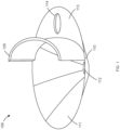
- FIG. 1 illustrates a perspective view of a liquid quality device 100, according to certain inventive techniques.
- the liquid quality device 100 includes a partitioning portion 110 and a weir 120.
- the partitioning portion 110 has a first region 111 and a second region 113, which may be separated by the weir 120.
- the partitioning portion 110 may be one integrated piece, or formed from separate pieces (e.g., the first region 111, the second region 113, the funnel (e.g., vortex-inducing region), etc. )
- the partitioning portion 110 and/or the weir 120 may include a material such as polyethylene or polypropylene.
- the partitioning portion 110 and weir 120 may be one integrated piece or may be separate pieces.
- the weir 120 may completely (or partially) separate the first region 111 from the second region 113.
- the weir 120 may have a curvature along a horizontal dimension, and this curvature may be concave when viewed from the first region 111.
- the curvature may be constant, or may have a curve with a varying radius as shown.
- the depicted curvature has shorter radiuses at the edges and one or more longer radiuses in the center.
- Such a varying-radius design may facilitate the creation of a relatively smooth transition between the weir 120 and the sidewall of a tubular portion (e.g., a manhole) in which the liquid quality device 100 is inserted (the "tubular portion" is discussed below).
- Tubular means to have a cross-sectional profile that can be round, oval, square, hexagonal, octagonal, or other some other shape. Such a varying curvature may assist in reducing turbulence (which may negatively impact the efficiency of the liquid quality device 100 to remove particulates). Alternatively, there may be no curvature, or there may be convex curvature in the weir 120, as viewed from the first region 111.
- the first region 111 includes a funnel (vortex-inducing region) and a sump inlet aperture 112 as depicted in FIG. 1 .
- the funnel may be designed to increase the length of time that the flow remains in the funnel and thus in a vortex. That in conjunction with the decreasing radius helps to maximize particulate separation.
- the second region 113 includes a sump outlet aperture 114.
- the second region 113 may have a generally flat profile in the horizontal dimension.
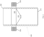
- FIG. 2 illustrates an elevational view, partially cross-sectioned, of the liquid quality device 100 in a manhole 200, according to certain inventive techniques.
- the manhole 200 may include a base 210, an inlet 220, and an outlet 230. Any one of the base 210, the inlet 220, and/or the outlet 230 may be integrated into the body of the manhole 200, or they may be separate pieces that work or connect together to achieve the functions described herein.
- the area between the liquid quality device 100 and the base 210 may be a sump region 240.
- liquid may flow into the manhole 200 through the inlet 220 and then into the sump region 240, thereby passing through the liquid quality device 100.
- the liquid may exit the sump region 240 through the liquid quality device 100 and then exit the manhole 200 through the outlet 230.
- FIG. 3 illustrates a top view of the liquid quality device 100 in the manhole 200 with an inline arrangement of the inlet 220 and outlet 230, according to certain inventive techniques.
- liquid enters the manhole 200 on one side through the inlet 220 and exits on the other side through the outlet 230.
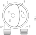
- FIG. 4 illustrates an offline arrangement, where liquid enters and exits on the same side of the manhole 200.
- Other arrangements are possible, such as liquid entering and exiting the manhole 200 at right angles or oblique angles.
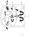
- FIG. 5A illustrates a sequence showing how liquid flows through the liquid quality device 100 in the manhole 200, according to certain inventive techniques.
- liquid which has suspended particulates
- the liquid enters the manhole 200 at a location above the liquid quality device 100, and more particularly above the first region 111.
- the liquid is inhibited from flowing into the second region 113 by the weir 120.
- the funnel of the liquid quality device 100 together with the weir 120 induces the liquid into a vortex.
- the liquid passes through the liquid quality device 100 via sump inlet aperture 112 and into the sump region 240 (e.g., the area in the manhole 200 between the liquid quality device 100 and the base 210).
- the liquid propagates into the sump region 240 in the general direction shown by the arrows. Once the liquid passes into the sump region 240, the vortex action may be reduced through detention time and energy losses. This may allow smaller pollutants that were not removed through the cyclonic action of the vortex in the funnel to settle out of the liquid.
- step E the liquid exits the sump region 240 through the sump outlet aperture 113.
- the liquid is now above the second region 113, and the weir 120 inhibits the liquid from flowing back into the first region 111.
- step F the liquid exits the manhole 200 through outlet 230.
- step G As the liquid level above the first region 111 rises, it will begin to, at step G, overtop the weir 120 and flow into an area above the second region 113. This liquid then exits the manhole 200 through the outlet 230, thereby bypassing the vortex-inducing steps. The overflowing liquid does not pass through the sump region 240, and therefore treatment is bypassed. By allowing a portion of the increased liquid flow to avoid the treatment area in the sump region 240, liquid flow velocities in the sump region 240 will be reduced. Consequently, there will be less of a problem with settled particulates being mixed back up with the liquid.
- the settled particulates can be cleaned out through either the sump inlet aperture 112, the sump outlet aperture 114, or an additional aperture (not shown) in the liquid quality device 100.
- a tube can be inserted through one or more of these apertures, and a vacuum can be applied through the tube.
- FIG. 5B illustrates a sequence showing how particulates are separated from a liquid by use of the liquid quality device 100 (depicted without the weir 120 for clarity in the illustration) in the manhole 200, according to certain inventive techniques.
- a vortex formed in the funnel region of the liquid quality device 100 pushes some of the relatively heavier particulates to the edges of the vortex (near the sides of the funnel) via a centrifugal force. These particles will then drop through the sump inlet aperture 112 into the sump region 240, landing on the base 210.
- Relatively lighter particulates will enter the sump region 240 and be carried upwards by the liquid flow. As these particulates are carried upward in the sump region 240, the liquid flow loses velocity. This allows these relatively lighter particulates to fall out of the liquid flow and onto the bottom of the sump region 240.
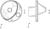
- FIGS. 6A-6D illustrate additional detail of optional details and/or features for the liquid quality device 100, according to certain inventive techniques.
- FIG. 6A illustrates a perspective view of the liquid quality device 100.
- FIG. 6B depicts an exploded view of the device 100.
- FIG. 6C shows a top view of the device.
- FIG. 6D illustrates an elevational view of the device 100.
- the partitioning portion 110 may have a groove sized and shaped to receive the weir 120.
- the groove may allow for proper and consistent placement of the weir 120 and may facilitate the weir 120 to be attached to the partitioning portion 110 through welding or fastening.
- the outer rim of the partitioning portion 110 may have a staircase profile with two or more levels, whereby the lower level(s) have larger radiuses than the higher level(s). This design may allow for convenient modifications for treatment flow rates by providing guides for different aperture sizes.
- Each of the sump inlet aperture 112 and/or sump outlet aperture 114 may also have a staircase profile with two or more levels, whereby a lower level of a given aperture may be narrower than an upper level. This allows for simple modifications for treatment flow rates by providing guides for different aperture sizes.
- the sump inlet aperture 112 also may have a flute (see FIG. 6D for a fuller profile of the flute) that extends downwardly from the funnel of the partitioning portion 110.
- Exemplary dimensions of the liquid quality device 100 are as follows.
- the partitioning portion 110 may have an outer diameter of approximately 1.19 m.
- the weir 120 may have a height of approximately 0.41 m.
- the widest diameter of the funnel along the longest horizontal axis may be approximately 0.87 m.
- the height of the funnel may be approximately 0.59 m.
- the groove may be approximately 0.05 m deep.
- the smallest level of the staircase profile in the sump inlet aperture 112 may be approximately 0.20 m in diameter.
- the widest aperture of the sump inlet aperture 112 may be approximately 0.25 m in diameter.
- the smallest level of the staircase profile in the sump outlet aperture 114 may be approximately 0.20 m in diameter, while the widest may be approximately 0.25 m in diameter. It may be possible to choose which size apertures 112, 114 are to be used on site or in a factory or facility. For example, narrow apertures (e.g., 0.20 m apertures) may be used for relatively lower flow applications (e.g ., 0.02 cubic metres per second).
- the narrower levels e.g., 0.20 m apertures
- the narrower levels may be removed, thereby leaving a wider levels (e.g., 10.25 m apertures).
- the wider apertures may be used for relatively higher flow applications (e.g., 0.03 cubic metres per second).
- the narrower level(s) may be removed with a knife or saw, thereby leaving the wider level(s).
- the liquid quality device 100 may not have different levels. It may be manufactured to have different dimensions (e.g ., different aperture 112, 114 sizes) in accordance with the principles discussed above.
- FIG. 7 illustrates a liquid quality device 700 with an alternative design and/or optional features, according to certain inventive techniques.
- the liquid quality device includes a partitioning portion 710 and a weir 720.
- the partitioning portion 710 may have a first region 711 and a second region 713, which may be separated by the weir 720.
- the weir 720 may completely (or partially) separate the first region 711 from the second region 713.
- the first region 711 includes a funnel and a sump inlet aperture 712 as depicted in FIG. 7 .
- the second region 713 includes a sump outlet aperture 714.
- the second region 713 may have a generally flat profile in the horizontal dimension.
- the liquid quality device 700 may also include a clean-out riser 730 that extends upwardly from an additional aperture (not visible in the figure because it is underneath the riser 730, but may be termed a sump access aperture) in the second region 713.
- a vacuum may be applied to the clean-out riser 730 to remove settled particulates from the sump region 240.
- the weir 720 may also have an aperture 721 (e.g., having a rectangular shape).
- the aperture size and location may be selected to allow an increased flow rate that falls between the design treatment rate and ultimate flow rate (approximately 3 x the treatment flow rate) to pass through the aperture 721 without overtopping the entire weir 720.
- the design treatment rate may be the flow rate of liquid that is intended to pass through the unit and receive treatment for the removal of particulates.
- the ultimate flow rate may be the total flow rate of the liquid that can pass through the unit (rate that receives treatment and rate that overtops the weir combined) without overflowing from the tubular structure. By not overtopping the weir 720, this may assist in containment of large debris and force it into the sump region 240.
- the additional liquid volume will overtop the weir 720 and exit the device 700.
- the influent is typically considered to have substantially reduced levels of particulates, and therefore in no need for treatment.
- this also helps reduce velocities in the sump region 240 which in turn helps to reduce the resuspension of the previously collected particulates.
- FIGS. 8-12 illustrate a liquid quality system 800 with an alternative design and/or optional features, according to certain inventive techniques.
- the liquid quality system 800 may include a liquid quality device 801, similar to the ones described above.
- the liquid quality device 801 may generally comprise, as described above, a partitioning portion 810 and a weir 820.
- the partitioning portion 810 has a first region 811 and a second region 813, which may be separated by the weir 820.
- the liquid quality system may include manhole 200, which may include a base 210, an inlet 220, and an outlet 230.
- any one of the base 210, the inlet 220, and/or the outlet 230 may be integrated into the body of the manhole 200, or they may be separate pieces that work or connect together to achieve the functions described herein.
- the liquid quality device 801 may be positioned in a manhole 200.
- the liquid quality system 800 may have a vertical central vertical axis (not shown), that runs the primary (longer) length of the system, including through the sump region 240, where a primary axial dimension runs parallel to, or along the central axis.
- the liquid quality system 800 may also include at least one drag-inducing portion(s) 850 and at least one supporting portion(s) 860.
- inducing a vortex in the liquid within a liquid quality system 800 may assist in removing particulates from the liquid.
- the liquid flow velocity and/or turbulence in the vortex in the sump region 240 are too great, the settled particulates may be mixed back up into the liquid, thus reducing the effectiveness of the liquid quality system.
- the introduction of drag-inducing portion(s) 850 may assist in reducing the liquid flow velocity and/or turbulence in vortex in the sump region 240.
- the drag-inducing portion(s) 850 may require a certain flow-rate to begin affecting the flow of the liquid in the sump region 240.
- the funnel may create a vortex in first region 811, causing liquid to flow through the sump inlet orifice 812 and shoot straight down into the sump region 240.
- the vortex induced by the funnel in the first region 811 may have enough rotational energy to create a vortex in the sump region 240 after the water passes through the sump inlet orifice 812.
- Such a vortex in the sump region 240 may have strong turbulence.
- the liquid flow velocity and/or the turbulence of the vortex in the sump region 240 may increase as the flow rate increases.
- one aspect of the present disclosure is to reduce such resuspension, also called "scour effect," of settled particulates in the sump region 240 by transforming the turbulent flow of the vortex into a controlled and increasingly laminar flow.
- liquid turbulence within the vortex may affect the behavior of the liquid flow and may also influence the settling characteristics of particulates in the flow.
- the greater the liquid turbulence and liquid flow velocity in the sump region 240 the more difficult it may be for particulates to settle, and the easier it may be for resuspension of particles to occur. Therefore, it may be desirable to create a longer, more laminar flow path to increase the amount of time which liquid remains in the sump region 240, thereby providing sufficient time for particulates to settle at the base 210 of the sump region 240.
- a second aspect of the present disclosure is to ensure optimal settling of particulates by creating a longer, more laminar flow path in the sump region 240.
- One way to create a longer, more laminar flow path may be to force the liquid to make smooth direction changes as it moves around the sump region 240 in the vortex.
- Another technique may guide the liquid away from the sump outlet aperture 814 to increase the amount of time that liquid remains in the sump region 240.
- one way to force smooth direction changes and guide the liquid flow away from the sump outlet aperture 814 is to position at least one drag-inducing portion(s) 850, which projects inwardly towards the central axis, proximate a sidewall of manhole 200 in the sump region 240.
- Proximate a sidewall means proximate to or on the side wall of the tubular portion of the manhole 200 in the sump region 240.
- Projecting inwardly towards the central axis means projecting, at least partially, towards the central axis.
- the drag-inducing portion(s) 850 may have several effects on liquid that passes over it including: creating drag to slow the liquid flow velocities in the vortex; extending the flow path by forcing a smooth direction change; and/or guiding liquid away from the sump outlet aperture 814.
- the orientation and angle of the drag- inducing portion(s) 850 may be chosen to achieve an enhanced settling efficiency.
- the impact of the drag-inducing portion(s) 850 may increase as the flow rate increases.
- the drag-inducing portion(s) 850 may have a solid or hollow body, and may displace some volume of the liquid in the sump region 240.
- the liquid in the flow is "split" and displaced by body of the drag inducing portion(s) 850.
- a boundary layer may form along the surface(s) of the drag-inducing portion(s) 850.
- the boundary layer may result in the liquid changing in viscosity and becoming more dense (i.e., viscous diffusion). Liquid with such a change in viscosity and density may be convected downstream until the flow separates.
- Such a splitting of the flow path may additionally aid in the settling of particulates.
- the combination of splitting the flow and forcing direction changes may result in particulates being knocked or falling out of the vortex flow.
- a plurality of drag-inducing portions 850 which project inwardly toward the central axis, are positioned proximate the sidewall of manhole 200 in the sump region 240.
- the drag-inducing portions 850 are attached to at least one supporting portion(s) 860, which may in turn be attached to the sidewall of the sump region 240.
- the word attached may mean directly or indirectly attached, such as directly attached to the sidewall of the sump region 240, or attached to the supporting portion 860, which are in turn attached to the sidewall of the sump region 240. Attached also may mean attached by an adhesive or by means of a screw or bolt configuration (not shown). Lastly, attached may mean attached as a single formed and integrated piece. Alternatively, the plurality of drag-inducing portions 850 may be directly attached the sidewall of the sump region 240.
- the drag-inducing portion(s) 850 may comprise a substantially triangular shape. Substantially triangular may mean that the corners may be rounded, or that other small variations may exist. In one embodiment, the drag-inducing portion(s) 850 may comprise an isosceles right triangle shape. Other shapes are also possible-for example: rectangles; squares; ovals; circles; other triangles; or various other polygons. The exposed tip of each drag-inducing portion 850 pointing at least partially towards the central axis of the sump region 240 may be rounded.
- the supporting portion(s) 860 may comprise vertical strips (e.g ., generally rectangular in shape) that may be positioned between the partitioning portion 810 and the base 210 proximate the sidewall of manhole 200 in the sump region 240. Moreover the plurality of supporting portion(s) 860 may be spaced equidistant around a perimeter of the sump region 240. A perimeter means proximate or on the sidewall of manhole 200 in the sump region 240. Alternatively, the plurality of supporting portion(s) 860 may be irregularly spaced around the perimeter of the sump region 240. The supporting portion(s) 860 may also comprise a different shape.
- the drag-inducing portion(s) 850 may be attached to a circumferential supporting portion(s) 860 (e.g., a toroid) (not shown).
- the supporting portion(s) 860 could be triangular, square, oval, parallelogram, etc. and may be positioned equidistant or irregularly around the perimeter of the sump region 240.
- the supporting portion(s) 860 may be attached to the sidewall of the sump region 240.
- the supporting portion(s) 860 may be integrated into the body of the manhole 200, and/or partitioning portion 810, and/or base 210, or they may be separate pieces that work or connect together to achieve the functions described herein.
- a plurality of supporting portions 860 may be beneficial for efficient manufacture and installation.
- One embodiment includes a first drag-inducing portion 850a, a second drag-inducing portion 850b, and a third drag-inducing portion 850c (collectively drag-inducing portions), each of which projects inwardly toward the central axis and is positioned proximate the sidewall of manhole 200 in the sump region 240.
- first supporting portion 860a a first supporting portion 860a, a second supporting portion 860b, a third supporting portion 860c, and a fourth supporting portion 860d (collectively, supporting portions), each of which may be may be positioned and/or attached proximate the sidewall of manhole 200 in the sump region 240.
- the supporting portions 860a, 860b, 860c, and 860d may be positioned equidistant around the perimeter of the sump region 240.
- the vertical positioning of drag- inducing portions 850a, 850b, 850c may be generally central on each of the supporting portions 860a, 860b, 860c, and 860d.
- more drag-inducing portions 850 and/or supporting portions 860 may be useful for larger diameter and/or taller sump regions 240.
- fewer drag-inducing portions 850 and/or supporting portions 860 may be useful for smaller diameter and/or shorter sump regions 240.
- the group of drag-inducing portions 850a, 850b, 850c may be positioned more towards the top or bottom on each of the supporting portions 860a, 860b, 860c, and 860d.
- supporting portions 860a and 860c may have a different configuration of drag-inducing portions 850a, 850b, 850c, than supporting portions 860b and 860d.
- the supporting portions 860a and 860c may face each other and have a first configuration and orientation of drag-inducing portions 850a, 850b, 850c.
- the supporting portions 860b and 860d may still face each other, but they may comprise a second, different configuration and/or orientation of drag-inducing portions 850a,850b,850c.
- drag-inducing portions 850a, 850b, 850c may be equidistantly vertically positioned along a primary axial dimension.
- the drag-inducing portions 850a, 850b, 850c may also be irregularly vertically positioned along a primary axial dimension.
- the drag-inducing portions 850a, 850b, 850c may each be oriented generally upwardly (e.g ., having a positive slope).
- the first drag-inducing portion 850(a) and the third drag-inducing portion 850(c) may be oriented in the same direction.
- first drag-inducing portion 850(a) and the third drag-inducing portion 850(c) may each be angled 60 degrees from a horizontal plane.
- the second drag-inducing portion 850(b) may have a mirrored orientation from the first drag-inducing portion 850(a) and the third drag-inducing portion 850(c).
- the second drag-inducing portion 850(b) may be angled 120 degrees from a horizontal plane. Smaller or larger positive angles are also possible for the orientation of the drag-inducing portions 850a, 850b, 850c in the first configuration.
- drag-inducing portions 850a, 850b, 850c may each be equidistantly vertically positioned along a primary axial dimension.
- the drag-inducing portions 850a, 850b, 850c may also be irregularly vertically positioned along a primary axial dimension.
- the drag-inducing portions 850a, 850b, 850c may each be oriented generally downwardly (e.g ., having a negative slope as compared to those drag-inducing portions in the first configuration).
- the first drag-inducing portion 850(a) and the third drag-inducing portion 850(c) may be oriented in the same direction.
- first drag-inducing portion 850(a) and the third drag-inducing portion 850(c) may each be angled -60 degrees from a horizontal plane.
- the second drag-inducing portion 850(b) may have a mirrored orientation from the first drag-inducing portion 850(a) and the third drag-inducing portion 850(c).
- the second drag-inducing portion 850(b) may be angled -120 degrees from a horizontal plane. Smaller or larger negative angles are also possible for the orientation of the drag-inducing portions 850a, 850b, 850c in the second configuration.
- the drag-inducing portions 850a, 850b, 850c in the first configuration may be respectively vertically offset from the drag-inducing portions 850a, 850b, 850c in the second configuration along a primary axial dimension as shown in FIG. 12 .
- the second drag-inducing portion 850b of each the first supporting portion 860a and third supporting portion 860c may be located at the same or substantially the same vertical position along a primary axial dimension as the first drag-inducing portion 850a of each the second supporting portion 860b and fourth supporting portion 860d.
- each the first supporting portion 860a and third supporting portion 860c may be located at the same or substantially the same vertical position along a primary axial dimension as the second drag-inducing portion 850b of each the second supporting portion 860b and fourth supporting portion 860d.
- Such an offset positioning of drag-inducing portions 850a, 850b, 850c between supporting portions 860a, 860b, 860c, and 860d may assisting in extending the length of the liquid flow path. For example, if the flow path is forced upward by the third drag-inducing portion 850c of the second supporting portion 860b or fourth supporting portion 860d, it may subsequently be forced downward by the third drag-inducing portion 850c of the first supporting portion 860a or fourth supporting portion 860c once the flow reaches there.
- the angular position of the drag-inducing portions 850a, 850b, 850c may be based off the principles of Stoke's Law and "inclined plate settling" techniques.
- the positioning of the drag-inducing portions 850 may help facilitate particulate settling.
- particulate settling may be facilitated by increasing the length of the flow path, reducing the vortex velocities, and reducing the settling distance by directing relatively smooth, laminar flow towards the bottom of the sump region.
- An angular positioning of 60 degrees may also allow particulates to slide down the drag-inducing portion(s) 850 and fall to the bottom of the sump region.
- a higher degree angle may decrease the settling efficiency, while an angle less than 45 degrees may lead to particulate accumulation on the drag-inducing portions.
Landscapes
- Chemical & Material Sciences (AREA)
- Engineering & Computer Science (AREA)
- Life Sciences & Earth Sciences (AREA)
- Hydrology & Water Resources (AREA)
- Water Supply & Treatment (AREA)
- Chemical Kinetics & Catalysis (AREA)
- Public Health (AREA)
- Health & Medical Sciences (AREA)
- Mechanical Engineering (AREA)
- Organic Chemistry (AREA)
- Environmental & Geological Engineering (AREA)
- Analytical Chemistry (AREA)
- Physical Or Chemical Processes And Apparatus (AREA)
- Cyclones (AREA)
- Sewage (AREA)
Description
- Generally, this application relates to techniques for removing sediment, debris, pollutants, and/or total suspended solids (all or some of which can be herein referred to as "particulates") from a liquid, such as storm-water runoff. In particular, this application discloses techniques for removing at least some particulates from storm-water runoff.
- Water runoff management (e.g., water generated by a rainfall) may be a challenging issue for landowners or municipalities. Not only does the flow of water have to be managed in order to reduce the risk of flooding, but particulates in the water should also be reduced, because such particulates reach rivers, ponds, lakes, or the ocean. Therefore, improved techniques of reducing particulates in water runoff are desired.
US 2009/020466 A1 discloses a separator tank for separating and trapping contaminants in rainwater and runoff.US 2014/021148 A1 discloses a system to separate solids from liquids. - According to certain techniques according to the disclosure, a system for removing particulates from liquid as described in the appended claims ia disclosed
- The first drag-inducing portion and second drag-inducing portion of each the first supporting portion and third supporting portion respectively may have a different orientation than the first drag-inducing portion and second drag-inducing portion of each the second supporting portion and fourth supporting portion. Additionally, the first drag- inducing portion, second drag-inducing portion, and third drag-inducing portion of each the first supporting portion and third supporting portion may be angled upwardly. Similarly, the first drag-inducing portion, second drag-inducing portion, and third drag-inducing portion of each the second supporting portion and fourth supporting portion may be angled downwardly.
- The first drag-inducing portion and third drag-inducing portion of each the first supporting portion and third supporting portion may be angled 60 degrees from a horizontal plane. The second drag-inducing portion of each the first supporting portion and third supporting portion may be angled 120 degrees from a horizontal plane. The first drag- inducing portion and third drag-inducing portion of each the second supporting portion and fourth supporting portion may be angled -60 degrees from a horizontal plane. The second drag-inducing portion of each the second supporting portion and fourth supporting portion may be angled -120 degrees from a horizontal plane.
- The second drag-inducing portion of each the first supporting portion and third supporting portion may be located at the same vertical position along a primary axial dimension as the first drag-inducing portion of each the second supporting portion and fourth supporting portion. Similarly, the third drag-inducing portion of each the first supporting portion and third supporting portion may be located at the same vertical position along a primary axial dimension as the second drag-inducing portion of each the second supporting portion and fourth supporting portion.
- The at least one drag-inducing portion may include a substantially triangular shape. Moreover, the supporting portion may be integrated with the partitioning portion.
- According to certain inventive techniques, a system for removing particulates from liquid and inducing drag in a liquid flow, wherein the system is configured for insertion into a manhole thereby creating a sump region below the system. The system includes a partitioning portion positionable above the sump region. The partitioning portion includes: a first region, which may include a funnel and a sump inlet aperture; and a second region, which includes a sump outlet aperture. The system also includes at least one drag-inducing portion positioned proximate a sidewall of the manhole in the sump region. The at least one drag-inducing portion projects inwardly towards a central axis in the sump region. The system also includes a weir extending upwardly from the partitioning portion and positioned between the first region from the second region.
- The at least one drag-inducing portion is attached to a supporting portion, which is positioned proximate to the sidewall of the manhole in the sump region. The system also includes: a first supporting portion; a second supporting portion; a third supporting portion; and a fourth supporting portion. Each of the first supporting portion, second supporting portion, third supporting portion and fourth supporting portion is positionable proximate to the sidewall of the manhole in the sump region and include: a first drag-inducing portion; a second drag-inducing portion located below the first drag-inducing portion; and a third drag-inducing portion located below the second drag-inducing portion.
-
-
FIG. 1 illustrates a perspective view of liquid quality device, according to certain inventive techniques. -
FIG. 2 illustrates an elevational view, partially cross-sectioned, of a liquid quality device in a manhole, according to certain inventive techniques. -
FIG. 3 illustrates a top view of a liquid quality device in a manhole with an inline arrangement, according to certain inventive techniques. -
FIG. 4 illustrates a top view of a liquid quality device in a manhole with an offline arrangement, according to certain inventive techniques. -
FIG. 5A illustrates a sequence showing how fluid flows through a liquid quality device in a manhole, according to certain inventive techniques. -
FIG. 5B illustrates a sequence showing how particulates are separated from a liquid by use of a liquid quality device in a manhole, according to certain inventive techniques. -
FIG. 6A illustrates a perspective view of a liquid quality device, according to certain inventive techniques. -
FIG. 6B illustrates a perspective and exploded view of a liquid quality device, according to certain inventive techniques. -
FIG. 6C illustrates a top view of a liquid quality device, according to certain inventive techniques. -
FIG. 6D illustrates an elevational view of a liquid quality device, according to certain inventive techniques. -
FIG. 7 illustrates a liquid quality device, according to certain inventive techniques. -
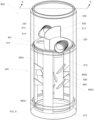
FIG. 8 illustrates liquid quality system including a plurality of drag-inducing portions attached to a supporting portion, according to certain inventive techniques. -
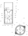
FIG. 9 illustrates a cross-sectional view of the liquid quality system including a plurality of drag-inducing portions taken along line 9-9 inFIG. 8 , according to certain inventive techniques. -
FIG. 10 illustrates a bottom-plan view of the liquid quality system including a plurality of drag-inducing portions according to certain inventive techniques. -
FIG. 11 illustrates a perspective view of a plurality of drag-inducing portions according to certain inventive techniques. -
FIG. 12 illustrates a front elevational view of a plurality of drag-inducing portions according to certain inventive techniques. - The foregoing summary, as well as the following detailed description of certain techniques of the present application, will be better understood when read in conjunction with the appended drawings. For the purposes of illustration, certain techniques are shown in the drawings. It should be understood, however, that the claims are not limited to the arrangements and instrumentality shown in the attached drawings. Furthermore, the appearance shown in the drawings is one of many ornamental appearances that can be employed to achieve the stated functions of the system.
- Parts Listing:
Number Description 100 liquid quality device 110 partitioning portion 111 first region 112 sump inlet aperture 113 second region 114 sump outlet aperture 120 weir 200 manhole 210 base 220 inlet 230 outlet 240 sump region 700 liquid quality device 710 partitioning portion 711 first region 712 sump inlet aperture 713 second region 714 sump outlet aperture 720 weir 721 aperture 730 clean- out riser 800 liquid quality system 801 liquid quality device 810 partitioning portion 811 first region 812 sump inlet aperture 813 second region 814 sump outlet aperture 820 weir 850 drag-inducing portion 860 supporting portion 850a first drag-inducing portion 850b second drag-inducing portion 850c third drag-inducing portion 860a first supporting portion 860b second supporting portion 860c third supporting portion 860d fourth supporting portion - A liquid quality system may be used to reduce particulates in liquid runoff (e.g., storm-water runoff). Some liquid quality system may induce a vortex in the liquid, causing suspended particulates to settle on the outside of the vortex, thereby separating the liquid from the particulates. However, if the velocity of the vortex is too great, the liquid flow may be very turbulent. Moreover, if the velocity of liquid flow is too great in the vortex, the settled particulates may be mixed back up into the liquid (resuspension). The combination of turbulence and resuspension may thus reduce the effectiveness of the liquid quality device.
- According to the techniques disclosed herein, an inventive liquid quality system may be better adapted to remove particulates by reducing the speed of the vortex and creating a long laminar liquid flow path. By forcing smooth direction changes in the flow path and directing the liquid flow away from the outlet, the overall length of the flow path may increase. Additionally, by subjecting the vortex to drag, the velocities within the vortex may decrease. These techniques may improve the effectiveness of the liquid quality device, and will be described in greater detail below.
-
FIG. 1 illustrates a perspective view of aliquid quality device 100, according to certain inventive techniques. Theliquid quality device 100 includes apartitioning portion 110 and aweir 120. Thepartitioning portion 110 has afirst region 111 and asecond region 113, which may be separated by theweir 120. Thepartitioning portion 110 may be one integrated piece, or formed from separate pieces (e.g., thefirst region 111, thesecond region 113, the funnel (e.g., vortex-inducing region), etc.) Thepartitioning portion 110 and/or theweir 120 may include a material such as polyethylene or polypropylene. Thepartitioning portion 110 andweir 120 may be one integrated piece or may be separate pieces. - The
weir 120 may completely (or partially) separate thefirst region 111 from thesecond region 113. As can be seen, theweir 120 may have a curvature along a horizontal dimension, and this curvature may be concave when viewed from thefirst region 111. The curvature may be constant, or may have a curve with a varying radius as shown. For example, the depicted curvature has shorter radiuses at the edges and one or more longer radiuses in the center. Such a varying-radius design may facilitate the creation of a relatively smooth transition between theweir 120 and the sidewall of a tubular portion (e.g., a manhole) in which theliquid quality device 100 is inserted (the "tubular portion" is discussed below). Tubular means to have a cross-sectional profile that can be round, oval, square, hexagonal, octagonal, or other some other shape. Such a varying curvature may assist in reducing turbulence (which may negatively impact the efficiency of theliquid quality device 100 to remove particulates). Alternatively, there may be no curvature, or there may be convex curvature in theweir 120, as viewed from thefirst region 111. - The
first region 111 includes a funnel (vortex-inducing region) and asump inlet aperture 112 as depicted inFIG. 1 . The funnel may be designed to increase the length of time that the flow remains in the funnel and thus in a vortex. That in conjunction with the decreasing radius helps to maximize particulate separation. Thesecond region 113 includes asump outlet aperture 114. Thesecond region 113 may have a generally flat profile in the horizontal dimension. - The size of the
apertures 112 and/or 114 may be determined by using the following equation:
- Where Q = flow rate in cubic feet per second;
- Cd = is the coefficient of discharge;
- A = area of the aperture in square feet;
- g = is the acceleration of gravity (32.2 ft./second2); and
- h = the head in feet acting on the aperture.
-
FIG. 2 illustrates an elevational view, partially cross-sectioned, of theliquid quality device 100 in amanhole 200, according to certain inventive techniques. Themanhole 200 may include abase 210, aninlet 220, and anoutlet 230. Any one of thebase 210, theinlet 220, and/or theoutlet 230 may be integrated into the body of themanhole 200, or they may be separate pieces that work or connect together to achieve the functions described herein. - The area between the
liquid quality device 100 and the base 210 may be asump region 240. As will be described in further detail with respect toFIG. 5 , liquid may flow into themanhole 200 through theinlet 220 and then into thesump region 240, thereby passing through theliquid quality device 100. The liquid may exit thesump region 240 through theliquid quality device 100 and then exit themanhole 200 through theoutlet 230. -
FIG. 3 illustrates a top view of theliquid quality device 100 in themanhole 200 with an inline arrangement of theinlet 220 andoutlet 230, according to certain inventive techniques. In this arrangement, liquid enters themanhole 200 on one side through theinlet 220 and exits on the other side through theoutlet 230.FIG. 4 illustrates an offline arrangement, where liquid enters and exits on the same side of themanhole 200. Other arrangements are possible, such as liquid entering and exiting themanhole 200 at right angles or oblique angles. -
FIG. 5A illustrates a sequence showing how liquid flows through theliquid quality device 100 in themanhole 200, according to certain inventive techniques. At step A, liquid (which has suspended particulates) may enter themanhole 200 through theinlet 220. The liquid enters themanhole 200 at a location above theliquid quality device 100, and more particularly above thefirst region 111. During lower liquid volume flow (e.g., the first flush), the liquid is inhibited from flowing into thesecond region 113 by theweir 120. - At step B, the funnel of the
liquid quality device 100 together with theweir 120 induces the liquid into a vortex. At step C, the liquid passes through theliquid quality device 100 viasump inlet aperture 112 and into the sump region 240 (e.g., the area in themanhole 200 between theliquid quality device 100 and the base 210). At step D, the liquid propagates into thesump region 240 in the general direction shown by the arrows. Once the liquid passes into thesump region 240, the vortex action may be reduced through detention time and energy losses. This may allow smaller pollutants that were not removed through the cyclonic action of the vortex in the funnel to settle out of the liquid. - At step E, the liquid exits the
sump region 240 through thesump outlet aperture 113. The liquid is now above thesecond region 113, and theweir 120 inhibits the liquid from flowing back into thefirst region 111. At step F, the liquid exits themanhole 200 throughoutlet 230. - As the liquid level above the
first region 111 rises, it will begin to, at step G, overtop theweir 120 and flow into an area above thesecond region 113. This liquid then exits themanhole 200 through theoutlet 230, thereby bypassing the vortex-inducing steps. The overflowing liquid does not pass through thesump region 240, and therefore treatment is bypassed. By allowing a portion of the increased liquid flow to avoid the treatment area in thesump region 240, liquid flow velocities in thesump region 240 will be reduced. Consequently, there will be less of a problem with settled particulates being mixed back up with the liquid. - After the event, the settled particulates can be cleaned out through either the
sump inlet aperture 112, thesump outlet aperture 114, or an additional aperture (not shown) in theliquid quality device 100. For example, a tube can be inserted through one or more of these apertures, and a vacuum can be applied through the tube. -
FIG. 5B illustrates a sequence showing how particulates are separated from a liquid by use of the liquid quality device 100 (depicted without theweir 120 for clarity in the illustration) in themanhole 200, according to certain inventive techniques. As depicted, a vortex formed in the funnel region of theliquid quality device 100 pushes some of the relatively heavier particulates to the edges of the vortex (near the sides of the funnel) via a centrifugal force. These particles will then drop through thesump inlet aperture 112 into thesump region 240, landing on thebase 210. - Relatively lighter particulates will enter the
sump region 240 and be carried upwards by the liquid flow. As these particulates are carried upward in thesump region 240, the liquid flow loses velocity. This allows these relatively lighter particulates to fall out of the liquid flow and onto the bottom of thesump region 240. -
FIGS. 6A-6D illustrate additional detail of optional details and/or features for theliquid quality device 100, according to certain inventive techniques.FIG. 6A illustrates a perspective view of theliquid quality device 100.FIG. 6B depicts an exploded view of thedevice 100.FIG. 6C shows a top view of the device.FIG. 6D illustrates an elevational view of thedevice 100. - With reference particularly to
FIG. 6B , it can be seen that thepartitioning portion 110 may have a groove sized and shaped to receive theweir 120. The groove may allow for proper and consistent placement of theweir 120 and may facilitate theweir 120 to be attached to thepartitioning portion 110 through welding or fastening. The outer rim of thepartitioning portion 110 may have a staircase profile with two or more levels, whereby the lower level(s) have larger radiuses than the higher level(s). This design may allow for convenient modifications for treatment flow rates by providing guides for different aperture sizes. Each of thesump inlet aperture 112 and/orsump outlet aperture 114 may also have a staircase profile with two or more levels, whereby a lower level of a given aperture may be narrower than an upper level. This allows for simple modifications for treatment flow rates by providing guides for different aperture sizes. Thesump inlet aperture 112 also may have a flute (seeFIG. 6D for a fuller profile of the flute) that extends downwardly from the funnel of thepartitioning portion 110. - Exemplary dimensions of the
liquid quality device 100 are as follows. Thepartitioning portion 110 may have an outer diameter of approximately 1.19 m. Theweir 120 may have a height of approximately 0.41 m. The widest diameter of the funnel along the longest horizontal axis may be approximately 0.87 m. The height of the funnel may be approximately 0.59 m. The groove may be approximately 0.05 m deep. - The smallest level of the staircase profile in the
sump inlet aperture 112 may be approximately 0.20 m in diameter. The widest aperture of thesump inlet aperture 112 may be approximately 0.25 m in diameter. Similarly, the smallest level of the staircase profile in thesump outlet aperture 114 may be approximately 0.20 m in diameter, while the widest may be approximately 0.25 m in diameter. It may be possible to choose whichsize apertures - The
liquid quality device 100 may not have different levels. It may be manufactured to have different dimensions (e.g.,different aperture -
FIG. 7 illustrates aliquid quality device 700 with an alternative design and/or optional features, according to certain inventive techniques. Similar to the one described above, the liquid quality device includes apartitioning portion 710 and aweir 720. Thepartitioning portion 710 may have afirst region 711 and asecond region 713, which may be separated by theweir 720. Theweir 720 may completely (or partially) separate thefirst region 711 from thesecond region 713. Thefirst region 711 includes a funnel and asump inlet aperture 712 as depicted inFIG. 7 . Thesecond region 713 includes asump outlet aperture 714. Thesecond region 713 may have a generally flat profile in the horizontal dimension. - The
liquid quality device 700 may also include a clean-outriser 730 that extends upwardly from an additional aperture (not visible in the figure because it is underneath theriser 730, but may be termed a sump access aperture) in thesecond region 713. A vacuum may be applied to the clean-outriser 730 to remove settled particulates from thesump region 240. - The
weir 720 may also have an aperture 721 (e.g., having a rectangular shape). The aperture size and location may be selected to allow an increased flow rate that falls between the design treatment rate and ultimate flow rate (approximately 3 x the treatment flow rate) to pass through theaperture 721 without overtopping theentire weir 720. The design treatment rate may be the flow rate of liquid that is intended to pass through the unit and receive treatment for the removal of particulates. The ultimate flow rate may be the total flow rate of the liquid that can pass through the unit (rate that receives treatment and rate that overtops the weir combined) without overflowing from the tubular structure. By not overtopping theweir 720, this may assist in containment of large debris and force it into thesump region 240. - As the flow rates in the
liquid quality device 700 approach the ultimate flow rate (again, approximately 3 x the treatment flow rate) the additional liquid volume will overtop theweir 720 and exit thedevice 700. As this point the influent is typically considered to have substantially reduced levels of particulates, and therefore in no need for treatment. By allowing the flows to overtop theweir 720, this also helps reduce velocities in thesump region 240 which in turn helps to reduce the resuspension of the previously collected particulates. -
FIGS. 8-12 illustrate aliquid quality system 800 with an alternative design and/or optional features, according to certain inventive techniques. Theliquid quality system 800 may include aliquid quality device 801, similar to the ones described above. Theliquid quality device 801 may generally comprise, as described above, apartitioning portion 810 and aweir 820. Thepartitioning portion 810 has afirst region 811 and asecond region 813, which may be separated by theweir 820. The liquid quality system may includemanhole 200, which may include abase 210, aninlet 220, and anoutlet 230. Any one of thebase 210, theinlet 220, and/or theoutlet 230 may be integrated into the body of themanhole 200, or they may be separate pieces that work or connect together to achieve the functions described herein. Theliquid quality device 801 may be positioned in amanhole 200. - The
liquid quality system 800 may have a vertical central vertical axis (not shown), that runs the primary (longer) length of the system, including through thesump region 240, where a primary axial dimension runs parallel to, or along the central axis. Theliquid quality system 800 may also include at least one drag-inducing portion(s) 850 and at least one supporting portion(s) 860. - As discussed above, inducing a vortex in the liquid within a
liquid quality system 800, may assist in removing particulates from the liquid. However, if the liquid flow velocity and/or turbulence in the vortex in thesump region 240 are too great, the settled particulates may be mixed back up into the liquid, thus reducing the effectiveness of the liquid quality system. The introduction of drag-inducing portion(s) 850 may assist in reducing the liquid flow velocity and/or turbulence in vortex in thesump region 240. - The drag-inducing portion(s) 850 may require a certain flow-rate to begin affecting the flow of the liquid in the
sump region 240. At lower flow rates the funnel may create a vortex infirst region 811, causing liquid to flow through thesump inlet orifice 812 and shoot straight down into thesump region 240. As the flow rate increases, so does the rotational energy of the liquid. Thus, at higher flow rates, the vortex induced by the funnel in thefirst region 811 may have enough rotational energy to create a vortex in thesump region 240 after the water passes through thesump inlet orifice 812. Such a vortex in thesump region 240 may have strong turbulence. The liquid flow velocity and/or the turbulence of the vortex in thesump region 240 may increase as the flow rate increases. - By controlling the liquid flow velocities and/or vortex in the
sump region 240, the filtering of particulates may be positively affected. As a result of a relatively high flow rate, the turbulent vortex may pick up already settled particulates from the floor of thesump region 240. Thus, one aspect of the present disclosure is to reduce such resuspension, also called "scour effect," of settled particulates in thesump region 240 by transforming the turbulent flow of the vortex into a controlled and increasingly laminar flow. - Aside from a relatively high liquid flow velocity, liquid turbulence within the vortex may affect the behavior of the liquid flow and may also influence the settling characteristics of particulates in the flow. Generally, the greater the liquid turbulence and liquid flow velocity in the
sump region 240, the more difficult it may be for particulates to settle, and the easier it may be for resuspension of particles to occur. Therefore, it may be desirable to create a longer, more laminar flow path to increase the amount of time which liquid remains in thesump region 240, thereby providing sufficient time for particulates to settle at thebase 210 of thesump region 240. Thus, a second aspect of the present disclosure is to ensure optimal settling of particulates by creating a longer, more laminar flow path in thesump region 240. One way to create a longer, more laminar flow path may be to force the liquid to make smooth direction changes as it moves around thesump region 240 in the vortex. Another technique may guide the liquid away from thesump outlet aperture 814 to increase the amount of time that liquid remains in thesump region 240. - For example, once a vortex is formed in the
sump region 240, one way to force smooth direction changes and guide the liquid flow away from thesump outlet aperture 814 is to position at least one drag-inducing portion(s) 850, which projects inwardly towards the central axis, proximate a sidewall ofmanhole 200 in thesump region 240. Proximate a sidewall means proximate to or on the side wall of the tubular portion of themanhole 200 in thesump region 240. Projecting inwardly towards the central axis means projecting, at least partially, towards the central axis. The drag-inducing portion(s) 850 may have several effects on liquid that passes over it including: creating drag to slow the liquid flow velocities in the vortex; extending the flow path by forcing a smooth direction change; and/or guiding liquid away from thesump outlet aperture 814. The orientation and angle of the drag- inducing portion(s) 850, as will be discussed in more detail below, may be chosen to achieve an enhanced settling efficiency. The impact of the drag-inducing portion(s) 850 may increase as the flow rate increases. - The drag-inducing portion(s) 850 may have a solid or hollow body, and may displace some volume of the liquid in the
sump region 240. Thus, when liquid flow passes by the body of the drag-inducing portion(s) 850, the liquid in the flow is "split" and displaced by body of the drag inducing portion(s) 850. As a result, a boundary layer may form along the surface(s) of the drag-inducing portion(s) 850. The boundary layer may result in the liquid changing in viscosity and becoming more dense (i.e., viscous diffusion). Liquid with such a change in viscosity and density may be convected downstream until the flow separates. Such a splitting of the flow path may additionally aid in the settling of particulates. The combination of splitting the flow and forcing direction changes may result in particulates being knocked or falling out of the vortex flow. - To effectively reduce the liquid flow velocity in the vortex and alter the flow path of liquid in the
sump region 240, a plurality of drag-inducingportions 850, which project inwardly toward the central axis, are positioned proximate the sidewall ofmanhole 200 in thesump region 240. The drag-inducingportions 850 are attached to at least one supporting portion(s) 860, which may in turn be attached to the sidewall of thesump region 240. The word attached may mean directly or indirectly attached, such as directly attached to the sidewall of thesump region 240, or attached to the supportingportion 860, which are in turn attached to the sidewall of thesump region 240. Attached also may mean attached by an adhesive or by means of a screw or bolt configuration (not shown). Lastly, attached may mean attached as a single formed and integrated piece. Alternatively, the plurality of drag-inducingportions 850 may be directly attached the sidewall of thesump region 240. - The drag-inducing portion(s) 850 may comprise a substantially triangular shape. Substantially triangular may mean that the corners may be rounded, or that other small variations may exist. In one embodiment, the drag-inducing portion(s) 850 may comprise an isosceles right triangle shape. Other shapes are also possible-for example: rectangles; squares; ovals; circles; other triangles; or various other polygons. The exposed tip of each drag-inducing
portion 850 pointing at least partially towards the central axis of thesump region 240 may be rounded. - As shown in
FIGS. 8 ,10 , the supporting portion(s) 860 may comprise vertical strips (e.g., generally rectangular in shape) that may be positioned between the partitioningportion 810 and the base 210 proximate the sidewall ofmanhole 200 in thesump region 240. Moreover the plurality of supporting portion(s) 860 may be spaced equidistant around a perimeter of thesump region 240. A perimeter means proximate or on the sidewall ofmanhole 200 in thesump region 240. Alternatively, the plurality of supporting portion(s) 860 may be irregularly spaced around the perimeter of thesump region 240. The supporting portion(s) 860 may also comprise a different shape. For example, the drag-inducing portion(s) 850 may be attached to a circumferential supporting portion(s) 860 (e.g., a toroid) (not shown). Alternatively, the supporting portion(s) 860 could be triangular, square, oval, parallelogram, etc. and may be positioned equidistant or irregularly around the perimeter of thesump region 240. Moreover, the supporting portion(s) 860 may be attached to the sidewall of thesump region 240. Additionally, the supporting portion(s) 860 may be integrated into the body of themanhole 200, and/orpartitioning portion 810, and/orbase 210, or they may be separate pieces that work or connect together to achieve the functions described herein. A plurality of supportingportions 860 may be beneficial for efficient manufacture and installation. - One embodiment, as shown in
FIGS. 8-10 , includes a first drag-inducingportion 850a, a second drag-inducingportion 850b, and a third drag-inducingportion 850c (collectively drag-inducing portions), each of which projects inwardly toward the central axis and is positioned proximate the sidewall ofmanhole 200 in thesump region 240. Four sets of the drag-inducingportions portion 860a, a second supportingportion 860b, a third supportingportion 860c, and a fourth supportingportion 860d (collectively, supporting portions), each of which may be may be positioned and/or attached proximate the sidewall ofmanhole 200 in thesump region 240. The supportingportions sump region 240. The vertical positioning of drag- inducingportions portions portions 850 and/or supportingportions 860 may be useful for larger diameter and/ortaller sump regions 240. By contrast, fewer drag-inducingportions 850 and/or supportingportions 860 may be useful for smaller diameter and/orshorter sump regions 240. Additionally, the group of drag-inducingportions portions - In one
embodiment supporting portions portions portions portions portions portions portions - As shown in
FIGS. 11, 12 , in the first configuration, drag-inducingportions portions portions portions - In the second configuration, drag-inducing
portions portions portions portions - The drag-inducing
portions portions FIG. 12 . In one embodiment the second drag-inducingportion 850b of each the first supportingportion 860a and third supportingportion 860c may be located at the same or substantially the same vertical position along a primary axial dimension as the first drag-inducingportion 850a of each the second supportingportion 860b and fourth supportingportion 860d. Likewise, the third drag-inducingportion 850c of each the first supportingportion 860a and third supportingportion 860c may be located at the same or substantially the same vertical position along a primary axial dimension as the second drag-inducingportion 850b of each the second supportingportion 860b and fourth supportingportion 860d. - Such an offset positioning of drag-inducing
portions portions portion 850c of the second supportingportion 860b or fourth supportingportion 860d, it may subsequently be forced downward by the third drag-inducingportion 850c of the first supportingportion 860a or fourth supportingportion 860c once the flow reaches there. - The angular position of the drag-inducing
portions portions 850 may help facilitate particulate settling. As previously discussed, particulate settling may be facilitated by increasing the length of the flow path, reducing the vortex velocities, and reducing the settling distance by directing relatively smooth, laminar flow towards the bottom of the sump region. An angular positioning of 60 degrees may also allow particulates to slide down the drag-inducing portion(s) 850 and fall to the bottom of the sump region. A higher degree angle may decrease the settling efficiency, while an angle less than 45 degrees may lead to particulate accumulation on the drag-inducing portions. - The size and orientation of the drag-inducing
portions 850 may be chosen in assistance with the following equations:

- Where: w is the settling distance from the inlet orifice to the bottom of the sump region;
- v is the settling velocity, in/s;
- Θ is the angle of the manhole from horizontal; and
- L is the length of the drag-inducing portions


- Where: up is the particle velocity;
- u is the fluid velocity;
- ρ is the fluid density;
- ρp is the particle density;
- gx is the gravity,
- x and Fx are additional forces such as body forces and forces due to pressure gradients; and
- FD is the drag force being composed of the liquid molecular viscosity µ, the particle diameter dp, the Reynolds number of the particle Rp and the drag coefficient Cd.
- It will be understood by those skilled in the art that various changes may be made and equivalents may be substituted without departing from the scope of the novel techniques disclosed in this application. In addition, many modifications may be made to adapt a particular situation or material to the teachings of the novel techniques without departing from its scope. Therefore, it is intended that the novel techniques not be limited to the particular techniques disclosed, but that they will include all techniques falling within the scope of the appended claims.
Claims (7)
- A system for removing particulates from liquid and inducing drag in a liquid flow, wherein the system is configured for insertion into a manhole (200) thereby creating a sump region (240) below the system, wherein the system comprises:a partitioning portion (710) positionable above the sump region (240), wherein the partitioning portion (710) includes:a first region (711) comprising a funnel and a sump inlet aperture (712);and a second region (713) comprising a sump outlet aperture (714);a plurality of drag-inducing portions (850a-c) positionable proximate a sidewall of the manhole in the sump region (240), and wherein the drag-inducing portions (850a-c) project inwardly when installed toward a central axis of the sump region (240);a first supporting portion (860a);a second supporting portion (860b);a third supporting portion (860c); and a fourth supporting portion (860d);wherein each of the first supporting portion (860a), second supporting portion (860b), third supporting portion (860c) and fourth supporting portion (860d) are positionable proximate to the sidewall of the manhole (200) in the sump region (240) and comprise:a first drag-inducing portion (850a);a second drag-inducing portion (850b) located below the first drag-inducing portion (850a); anda third drag-inducing portion (850c) located below the second drag-inducing portion (850b); wherein the first drag-inducing portions (850a), the second drag-inducing portions (850b) and the third drag-inducing portions (850c) are attached to each of said first to fourth supporting portions (860a-d); anda weir (720) extending upwardly from the partitioning portion (710) and positioned between the first region (711) from the second region (713).
- The system of claim 1, wherein the first drag-inducing portion (850a) and second drag-inducing portion (850b) of each the first supporting portion (860a) and third supporting portion (860c) respectively have a different orientation than the first drag-inducing portion (850a) and second drag-inducing portion (850b) of each the second supporting portion (860b) and fourth supporting portion (860d).
- The system of claim 2, wherein each drag-inducing portion (850a-c) comprises a substantially triangular shape, and wherein:the first drag-inducing portion (850a), second drag-inducing portion (850b), and third drag- inducing portion (850c) of each the first supporting portion (860a) and third supporting portion (850c) are angled upwardly; andthe first drag-inducing portion (850a), second drag-inducing portion (850b), and third drag- inducing portion (850c) of each the second supporting portion (860b) and fourth supporting portion (860d) are angled downwardly.
- The system of claim 3 wherein:the first drag-inducing portion (850a) and third drag-inducing portion (850c) of each the first supporting portion (860a) and third supporting portion (860c) are angled 60 degrees from a horizontal plane;the second drag-inducing portion (850b) of each the first supporting portion (860a) and third supporting portion (860c) is angled 120 degrees from a horizontal plane;the first drag-inducing portion (850a) and third drag-inducing portion (850c) of each the second supporting portion (860b) and fourth supporting portion (860d) are angled -60 degrees from a horizontal plane; andthe second drag-inducing portion (850b) of each the second supporting portion (860b) and fourth supporting portion (860d) is angled -120 degrees from a horizontal plane.
- The system of claim 4, wherein:the second drag-inducing portion (850b) of each the first supporting portion (860a) and third supporting portion (860c) is located at the same vertical position along a primary axial dimension as the first drag-inducing portion (850a) of each the second supporting portion (860b) and fourth supporting portion (860d); andthe third drag-inducing portion (850c) of each the first supporting portion (860a) and third supporting portion (860c) is located at the same vertical position along a primary axial dimension as the second drag-inducing portion (850b) of each the second supporting portion (860b) and fourth supporting portion (860d).
- The system of claim 1, wherein each drag-inducing portion (850a-c) comprises a substantially triangular shape.
- The system of claim 1, wherein the supporting portion (860a-d) is integrated with the partitioning portion (710).
Applications Claiming Priority (3)
| Application Number | Priority Date | Filing Date | Title |
|---|---|---|---|
| US201762463322P | 2017-02-24 | 2017-02-24 | |
| US15/646,794 US10309089B2 (en) | 2017-02-24 | 2017-07-11 | Liquid quality system with drag inducing portions |
| PCT/US2018/019382 WO2018156871A1 (en) | 2017-02-24 | 2018-02-23 | Liquid quality system with drag inducing portions |
Publications (3)
| Publication Number | Publication Date |
|---|---|
| EP3585497A1 EP3585497A1 (en) | 2020-01-01 |
| EP3585497A4 EP3585497A4 (en) | 2020-12-09 |
| EP3585497B1 true EP3585497B1 (en) | 2024-12-18 |
Family
ID=63246101
Family Applications (1)
| Application Number | Title | Priority Date | Filing Date |
|---|---|---|---|
| EP18758004.8A Active EP3585497B1 (en) | 2017-02-24 | 2018-02-23 | Liquid quality system with drag inducing portions |
Country Status (6)
| Country | Link |
|---|---|
| US (2) | US10309089B2 (en) |
| EP (1) | EP3585497B1 (en) |
| CA (1) | CA3054727C (en) |
| MX (1) | MX392566B (en) |
| SA (1) | SA519402524B1 (en) |
| WO (1) | WO2018156871A1 (en) |
Families Citing this family (7)
| Publication number | Priority date | Publication date | Assignee | Title |
|---|---|---|---|---|
| US10309089B2 (en) * | 2017-02-24 | 2019-06-04 | Advanced Drainage Systems, Inc. | Liquid quality system with drag inducing portions |
| US11041301B2 (en) | 2017-11-17 | 2021-06-22 | Advanced Drainage Systems, Inc. | Method for installing a liquid quality system |
| US11642610B2 (en) | 2018-11-13 | 2023-05-09 | Leigh MAXWELL | Vortex inducing device and a method of use thereof for concentrating sediment in a water tank |
| US11713569B2 (en) | 2020-08-12 | 2023-08-01 | Contech Engineered Solutions LLC | Stormwater treatment device |
| US12420219B2 (en) | 2020-08-12 | 2025-09-23 | Contech Engineered Solutions LLC | Stormwater treatment device |
| CN112390417B (en) * | 2020-11-16 | 2021-06-18 | 王凤梅 | A sewage emergency treatment device for municipal sewage treatment |
| US11033835B1 (en) | 2020-11-24 | 2021-06-15 | Advanced Drainage Systems, Inc. | Liquid quality system with drag-inducing portions |
Family Cites Families (29)
| Publication number | Priority date | Publication date | Assignee | Title |
|---|---|---|---|---|
| US2378632A (en) | 1942-07-27 | 1945-06-19 | Hooker Jr | Apparatus for separating solids from liquids |
| NL295058A (en) | 1962-07-07 | 1900-01-01 | ||
| US3847813A (en) | 1972-12-27 | 1974-11-12 | Gen Electric | Coalescing plate for fluid mixture plate separator |
| US4643834A (en) | 1986-02-03 | 1987-02-17 | Filter Plate Company | Separation system using coalescing techniques |
| US4722800A (en) | 1986-05-30 | 1988-02-02 | Highland Tank And Manufacturing Company | Oil-water separator |
| US5004534A (en) | 1988-05-16 | 1991-04-02 | Vincenzo Buzzelli | Catch basin |
| US4897206A (en) | 1988-11-30 | 1990-01-30 | Facet Quantek, Inc. | Bidirectionally corrugated plate separator for fluid mixtures |
| US5762810A (en) | 1996-11-22 | 1998-06-09 | Pelton; Paul | Coalescing oil/water separator |
| US5849181A (en) | 1997-06-02 | 1998-12-15 | Stormceptor Corporation | Catch basin |
| US6315131B1 (en) * | 1999-03-22 | 2001-11-13 | Universal Separators, Inc. | Multi-directional flow gravity Separator |
| US6068765A (en) | 1999-03-26 | 2000-05-30 | Stormceptor Corporation | Separator tank |
| US6371690B1 (en) | 2000-12-07 | 2002-04-16 | Joseph Gordon Monteith | Method and apparatus for handling water at low and high feed rates |
| US7238281B2 (en) * | 2005-07-18 | 2007-07-03 | Ohio University | Storm water runoff treatment system |
| KR100549738B1 (en) * | 2005-07-27 | 2006-02-13 | 박노연 | Vortex Separator for Rainwater |
| FI122057B (en) * | 2006-10-30 | 2011-08-15 | Outotec Oyj | Thickening and thickening procedure |
| CA2677078A1 (en) | 2007-02-01 | 2008-08-07 | Imbrium Systems Corp. | Pollutant trap |
| US7666303B2 (en) | 2007-07-20 | 2010-02-23 | Monteco Ltd. | Seperator tank |
| US8221618B2 (en) | 2007-08-15 | 2012-07-17 | Monteco Ltd. | Filter for removing sediment from water |
| US8123935B2 (en) | 2007-08-15 | 2012-02-28 | Monteco Ltd. | Filter for removing sediment from water |
| US8287726B2 (en) | 2007-08-15 | 2012-10-16 | Monteco Ltd | Filter for removing sediment from water |
| US7682509B2 (en) | 2008-01-17 | 2010-03-23 | Green Turtle Americas Ltd. | Trap for removing material from a fluid stream |
| US8308959B2 (en) * | 2010-04-23 | 2012-11-13 | Express Energy Operating LP | Material separator |
| US8865006B2 (en) * | 2011-08-15 | 2014-10-21 | Jeff Ford | Concrete washout separation system |
| US9222248B2 (en) * | 2012-03-28 | 2015-12-29 | Jensen Enterprises, Inc. | Stormwater treatment device |
| US9056266B2 (en) | 2012-07-21 | 2015-06-16 | Don M. Buckner | Method and system to separate solids from liquids |
| US9827510B2 (en) | 2014-12-08 | 2017-11-28 | Contech Engineered Solutions LLC | Hydrodynamic separator |
| CN105089135B (en) | 2015-09-16 | 2017-05-10 | 江苏河马井股份有限公司 | Pre-mounted rainwater treatment device |
| US20170240438A1 (en) * | 2016-02-22 | 2017-08-24 | Advanced Drainage Systems, Inc. | Liquid quality device with weir |
| US10309089B2 (en) * | 2017-02-24 | 2019-06-04 | Advanced Drainage Systems, Inc. | Liquid quality system with drag inducing portions |
-
2017
- 2017-07-11 US US15/646,794 patent/US10309089B2/en active Active
-
2018
- 2018-02-23 EP EP18758004.8A patent/EP3585497B1/en active Active
- 2018-02-23 WO PCT/US2018/019382 patent/WO2018156871A1/en not_active Ceased
- 2018-02-23 CA CA3054727A patent/CA3054727C/en active Active
- 2018-02-23 MX MX2019010154A patent/MX392566B/en unknown
-
2019
- 2019-05-31 US US16/428,398 patent/US10982424B2/en active Active
- 2019-08-25 SA SA519402524A patent/SA519402524B1/en unknown
Also Published As
| Publication number | Publication date |
|---|---|
| US10309089B2 (en) | 2019-06-04 |
| CA3054727C (en) | 2022-07-12 |
| WO2018156871A1 (en) | 2018-08-30 |
| US10982424B2 (en) | 2021-04-20 |
| US20180245327A1 (en) | 2018-08-30 |
| SA519402524B1 (en) | 2022-04-07 |
| EP3585497A4 (en) | 2020-12-09 |
| EP3585497A1 (en) | 2020-01-01 |
| BR112019017737A2 (en) | 2020-03-31 |
| MX392566B (en) | 2025-03-24 |
| CA3054727A1 (en) | 2018-08-30 |
| US20190284790A1 (en) | 2019-09-19 |
| MX2019010154A (en) | 2020-02-05 |
Similar Documents
| Publication | Publication Date | Title |
|---|---|---|
| US10982424B2 (en) | Liquid quality system with drag inducing portions | |
| US7666303B2 (en) | Seperator tank | |
| US4132651A (en) | Separating device to separate two liquids of different specific gravity | |
| US11624179B2 (en) | Method for installing a liquid quality system | |
| GB1563586A (en) | Separating device to separate two liquids of different specific gravity | |
| US20190210894A1 (en) | Hydrodynamic separators, assemblies and methods for storm water treatment | |
| US20170240438A1 (en) | Liquid quality device with weir | |
| US4366058A (en) | High efficiency settling system | |
| US20230256361A1 (en) | Liquid quality system with drag-inducing portions | |
| US4976875A (en) | Method of and apparatus for separating a medium in different components by means of gravity | |
| CN104254378A (en) | Wastewater treatment plant | |
| JP5732630B2 (en) | Solid-liquid separator using liquid cyclone | |
| BR112019017737B1 (en) | SYSTEM FOR REMOVING PARTICULATES FROM LIQUID AND INDUCING DRAG IN A LIQUID FLOW |
Legal Events
| Date | Code | Title | Description |
|---|---|---|---|
| STAA | Information on the status of an ep patent application or granted ep patent |
Free format text: STATUS: THE INTERNATIONAL PUBLICATION HAS BEEN MADE |
|
| PUAI | Public reference made under article 153(3) epc to a published international application that has entered the european phase |
Free format text: ORIGINAL CODE: 0009012 |
|
| STAA | Information on the status of an ep patent application or granted ep patent |
Free format text: STATUS: REQUEST FOR EXAMINATION WAS MADE |
|
| 17P | Request for examination filed |
Effective date: 20190913 |
|
| AK | Designated contracting states |
Kind code of ref document: A1 Designated state(s): AL AT BE BG CH CY CZ DE DK EE ES FI FR GB GR HR HU IE IS IT LI LT LU LV MC MK MT NL NO PL PT RO RS SE SI SK SM TR |
|
| AX | Request for extension of the european patent |
Extension state: BA ME |
|
| DAV | Request for validation of the european patent (deleted) | ||
| DAX | Request for extension of the european patent (deleted) | ||
| REG | Reference to a national code |
Ref country code: HK Ref legal event code: DE Ref document number: 40021170 Country of ref document: HK |
|
| A4 | Supplementary search report drawn up and despatched |
Effective date: 20201111 |
|
| RIC1 | Information provided on ipc code assigned before grant |
Ipc: B01D 21/26 20060101AFI20201105BHEP Ipc: C02F 103/00 20060101ALI20201105BHEP Ipc: E03F 5/14 20060101ALI20201105BHEP Ipc: B01D 21/00 20060101ALI20201105BHEP Ipc: C02F 1/38 20060101ALI20201105BHEP Ipc: B01D 21/24 20060101ALI20201105BHEP Ipc: E03F 1/00 20060101ALI20201105BHEP Ipc: E03F 5/04 20060101ALI20201105BHEP |
|
| STAA | Information on the status of an ep patent application or granted ep patent |
Free format text: STATUS: EXAMINATION IS IN PROGRESS |
|
| 17Q | First examination report despatched |
Effective date: 20230207 |
|
| P01 | Opt-out of the competence of the unified patent court (upc) registered |
Effective date: 20230516 |
|
| GRAP | Despatch of communication of intention to grant a patent |
Free format text: ORIGINAL CODE: EPIDOSNIGR1 |
|
| STAA | Information on the status of an ep patent application or granted ep patent |
Free format text: STATUS: GRANT OF PATENT IS INTENDED |
|
| INTG | Intention to grant announced |
Effective date: 20240729 |
|
| GRAS | Grant fee paid |
Free format text: ORIGINAL CODE: EPIDOSNIGR3 |
|
| GRAA | (expected) grant |
Free format text: ORIGINAL CODE: 0009210 |
|
| STAA | Information on the status of an ep patent application or granted ep patent |
Free format text: STATUS: THE PATENT HAS BEEN GRANTED |
|
| AK | Designated contracting states |
Kind code of ref document: B1 Designated state(s): AL AT BE BG CH CY CZ DE DK EE ES FI FR GB GR HR HU IE IS IT LI LT LU LV MC MK MT NL NO PL PT RO RS SE SI SK SM TR |
|
| REG | Reference to a national code |
Ref country code: GB Ref legal event code: FG4D |
|
| REG | Reference to a national code |
Ref country code: CH Ref legal event code: EP |
|
| REG | Reference to a national code |
Ref country code: DE Ref legal event code: R096 Ref document number: 602018077715 Country of ref document: DE |
|
| REG | Reference to a national code |
Ref country code: IE Ref legal event code: FG4D |
|
| REG | Reference to a national code |
Ref country code: LT Ref legal event code: MG9D |
|
| PG25 | Lapsed in a contracting state [announced via postgrant information from national office to epo] |
Ref country code: HR Free format text: LAPSE BECAUSE OF FAILURE TO SUBMIT A TRANSLATION OF THE DESCRIPTION OR TO PAY THE FEE WITHIN THE PRESCRIBED TIME-LIMIT Effective date: 20241218 |
|
| PG25 | Lapsed in a contracting state [announced via postgrant information from national office to epo] |
Ref country code: FI Free format text: LAPSE BECAUSE OF FAILURE TO SUBMIT A TRANSLATION OF THE DESCRIPTION OR TO PAY THE FEE WITHIN THE PRESCRIBED TIME-LIMIT Effective date: 20241218 |
|
| PG25 | Lapsed in a contracting state [announced via postgrant information from national office to epo] |
Ref country code: BG Free format text: LAPSE BECAUSE OF FAILURE TO SUBMIT A TRANSLATION OF THE DESCRIPTION OR TO PAY THE FEE WITHIN THE PRESCRIBED TIME-LIMIT Effective date: 20241218 |
|
| PG25 | Lapsed in a contracting state [announced via postgrant information from national office to epo] |
Ref country code: NO Free format text: LAPSE BECAUSE OF FAILURE TO SUBMIT A TRANSLATION OF THE DESCRIPTION OR TO PAY THE FEE WITHIN THE PRESCRIBED TIME-LIMIT Effective date: 20250318 |
|
| REG | Reference to a national code |
Ref country code: NL Ref legal event code: MP Effective date: 20241218 |
|
| PG25 | Lapsed in a contracting state [announced via postgrant information from national office to epo] |
Ref country code: LV Free format text: LAPSE BECAUSE OF FAILURE TO SUBMIT A TRANSLATION OF THE DESCRIPTION OR TO PAY THE FEE WITHIN THE PRESCRIBED TIME-LIMIT Effective date: 20241218 Ref country code: GR Free format text: LAPSE BECAUSE OF FAILURE TO SUBMIT A TRANSLATION OF THE DESCRIPTION OR TO PAY THE FEE WITHIN THE PRESCRIBED TIME-LIMIT Effective date: 20250319 |
|
| PG25 | Lapsed in a contracting state [announced via postgrant information from national office to epo] |
Ref country code: RS Free format text: LAPSE BECAUSE OF FAILURE TO SUBMIT A TRANSLATION OF THE DESCRIPTION OR TO PAY THE FEE WITHIN THE PRESCRIBED TIME-LIMIT Effective date: 20250318 |
|
| PG25 | Lapsed in a contracting state [announced via postgrant information from national office to epo] |
Ref country code: NL Free format text: LAPSE BECAUSE OF FAILURE TO SUBMIT A TRANSLATION OF THE DESCRIPTION OR TO PAY THE FEE WITHIN THE PRESCRIBED TIME-LIMIT Effective date: 20241218 |
|
| REG | Reference to a national code |
Ref country code: AT Ref legal event code: MK05 Ref document number: 1751808 Country of ref document: AT Kind code of ref document: T Effective date: 20241218 |
|
| PG25 | Lapsed in a contracting state [announced via postgrant information from national office to epo] |
Ref country code: SM Free format text: LAPSE BECAUSE OF FAILURE TO SUBMIT A TRANSLATION OF THE DESCRIPTION OR TO PAY THE FEE WITHIN THE PRESCRIBED TIME-LIMIT Effective date: 20241218 |
|
| PG25 | Lapsed in a contracting state [announced via postgrant information from national office to epo] |
Ref country code: PL Free format text: LAPSE BECAUSE OF FAILURE TO SUBMIT A TRANSLATION OF THE DESCRIPTION OR TO PAY THE FEE WITHIN THE PRESCRIBED TIME-LIMIT Effective date: 20241218 |
|
| PG25 | Lapsed in a contracting state [announced via postgrant information from national office to epo] |
Ref country code: ES Free format text: LAPSE BECAUSE OF FAILURE TO SUBMIT A TRANSLATION OF THE DESCRIPTION OR TO PAY THE FEE WITHIN THE PRESCRIBED TIME-LIMIT Effective date: 20241218 |
|
| PG25 | Lapsed in a contracting state [announced via postgrant information from national office to epo] |
Ref country code: IS Free format text: LAPSE BECAUSE OF FAILURE TO SUBMIT A TRANSLATION OF THE DESCRIPTION OR TO PAY THE FEE WITHIN THE PRESCRIBED TIME-LIMIT Effective date: 20250418 |
|
| PG25 | Lapsed in a contracting state [announced via postgrant information from national office to epo] |
Ref country code: PT Free format text: LAPSE BECAUSE OF FAILURE TO SUBMIT A TRANSLATION OF THE DESCRIPTION OR TO PAY THE FEE WITHIN THE PRESCRIBED TIME-LIMIT Effective date: 20250421 |
|
| PG25 | Lapsed in a contracting state [announced via postgrant information from national office to epo] |
Ref country code: EE Free format text: LAPSE BECAUSE OF FAILURE TO SUBMIT A TRANSLATION OF THE DESCRIPTION OR TO PAY THE FEE WITHIN THE PRESCRIBED TIME-LIMIT Effective date: 20241218 |
|
| PG25 | Lapsed in a contracting state [announced via postgrant information from national office to epo] |
Ref country code: AT Free format text: LAPSE BECAUSE OF FAILURE TO SUBMIT A TRANSLATION OF THE DESCRIPTION OR TO PAY THE FEE WITHIN THE PRESCRIBED TIME-LIMIT Effective date: 20241218 Ref country code: RO Free format text: LAPSE BECAUSE OF FAILURE TO SUBMIT A TRANSLATION OF THE DESCRIPTION OR TO PAY THE FEE WITHIN THE PRESCRIBED TIME-LIMIT Effective date: 20241218 |
|
| PG25 | Lapsed in a contracting state [announced via postgrant information from national office to epo] |
Ref country code: SK Free format text: LAPSE BECAUSE OF FAILURE TO SUBMIT A TRANSLATION OF THE DESCRIPTION OR TO PAY THE FEE WITHIN THE PRESCRIBED TIME-LIMIT Effective date: 20241218 |
|
| PG25 | Lapsed in a contracting state [announced via postgrant information from national office to epo] |
Ref country code: CZ Free format text: LAPSE BECAUSE OF FAILURE TO SUBMIT A TRANSLATION OF THE DESCRIPTION OR TO PAY THE FEE WITHIN THE PRESCRIBED TIME-LIMIT Effective date: 20241218 |
|
| PG25 | Lapsed in a contracting state [announced via postgrant information from national office to epo] |
Ref country code: IT Free format text: LAPSE BECAUSE OF FAILURE TO SUBMIT A TRANSLATION OF THE DESCRIPTION OR TO PAY THE FEE WITHIN THE PRESCRIBED TIME-LIMIT Effective date: 20241218 |
|
| PG25 | Lapsed in a contracting state [announced via postgrant information from national office to epo] |
Ref country code: SE Free format text: LAPSE BECAUSE OF FAILURE TO SUBMIT A TRANSLATION OF THE DESCRIPTION OR TO PAY THE FEE WITHIN THE PRESCRIBED TIME-LIMIT Effective date: 20241218 |
|
| PG25 | Lapsed in a contracting state [announced via postgrant information from national office to epo] |
Ref country code: MC Free format text: LAPSE BECAUSE OF FAILURE TO SUBMIT A TRANSLATION OF THE DESCRIPTION OR TO PAY THE FEE WITHIN THE PRESCRIBED TIME-LIMIT Effective date: 20241218 |
|
| REG | Reference to a national code |
Ref country code: DE Ref legal event code: R097 Ref document number: 602018077715 Country of ref document: DE |
|
| REG | Reference to a national code |
Ref country code: CH Ref legal event code: PL |
|
| PG25 | Lapsed in a contracting state [announced via postgrant information from national office to epo] |
Ref country code: DK Free format text: LAPSE BECAUSE OF FAILURE TO SUBMIT A TRANSLATION OF THE DESCRIPTION OR TO PAY THE FEE WITHIN THE PRESCRIBED TIME-LIMIT Effective date: 20241218 |
|
| PG25 | Lapsed in a contracting state [announced via postgrant information from national office to epo] |
Ref country code: LU Free format text: LAPSE BECAUSE OF NON-PAYMENT OF DUE FEES Effective date: 20250223 |
|
| PG25 | Lapsed in a contracting state [announced via postgrant information from national office to epo] |
Ref country code: CH Free format text: LAPSE BECAUSE OF NON-PAYMENT OF DUE FEES Effective date: 20250228 |
|
| PLBE | No opposition filed within time limit |
Free format text: ORIGINAL CODE: 0009261 |
|
| STAA | Information on the status of an ep patent application or granted ep patent |
Free format text: STATUS: NO OPPOSITION FILED WITHIN TIME LIMIT |
|
| 26N | No opposition filed |
Effective date: 20250919 |
|
| REG | Reference to a national code |
Ref country code: BE Ref legal event code: MM Effective date: 20250228 |
|
| PG25 | Lapsed in a contracting state [announced via postgrant information from national office to epo] |
Ref country code: BE Free format text: LAPSE BECAUSE OF NON-PAYMENT OF DUE FEES Effective date: 20250228 |
|
| PGFP | Annual fee paid to national office [announced via postgrant information from national office to epo] |
Ref country code: GB Payment date: 20260227 Year of fee payment: 9 |
|
| PGFP | Annual fee paid to national office [announced via postgrant information from national office to epo] |
Ref country code: DE Payment date: 20260227 Year of fee payment: 9 Ref country code: IE Payment date: 20260227 Year of fee payment: 9 |
|
| PGFP | Annual fee paid to national office [announced via postgrant information from national office to epo] |
Ref country code: FR Payment date: 20260225 Year of fee payment: 9 |