EP3585227B1 - Mounting method and/or apparatus for mounting a toilet seat - Google Patents
Mounting method and/or apparatus for mounting a toilet seat Download PDFInfo
- Publication number
- EP3585227B1 EP3585227B1 EP17708873.9A EP17708873A EP3585227B1 EP 3585227 B1 EP3585227 B1 EP 3585227B1 EP 17708873 A EP17708873 A EP 17708873A EP 3585227 B1 EP3585227 B1 EP 3585227B1
- Authority
- EP
- European Patent Office
- Prior art keywords
- hinge
- pan
- base
- fixing
- contact surface
- Prior art date
- Legal status (The legal status is an assumption and is not a legal conclusion. Google has not performed a legal analysis and makes no representation as to the accuracy of the status listed.)
- Active
Links
Images

Classifications
-
- A—HUMAN NECESSITIES
- A47—FURNITURE; DOMESTIC ARTICLES OR APPLIANCES; COFFEE MILLS; SPICE MILLS; SUCTION CLEANERS IN GENERAL
- A47K—SANITARY EQUIPMENT; ACCESSORIES THEREFOR, e.g. TOILET ACCESSORIES
- A47K13/00—Seats or covers for all kinds of closets
- A47K13/24—Parts or details not covered in, or of interest apart from, groups A47K13/02 - A47K13/22
- A47K13/26—Mounting devices for seats or covers
-
- A—HUMAN NECESSITIES
- A47—FURNITURE; DOMESTIC ARTICLES OR APPLIANCES; COFFEE MILLS; SPICE MILLS; SUCTION CLEANERS IN GENERAL
- A47K—SANITARY EQUIPMENT; ACCESSORIES THEREFOR, e.g. TOILET ACCESSORIES
- A47K13/00—Seats or covers for all kinds of closets
- A47K13/12—Hinges
Definitions
- This invention provides an a apparatus for mounting a toilet seat on a toilet pan.
- a toilet seat is typically fixed to a toilet pan by way of two spaced hinges fixed to spaced positions on or adjacent to the rear edge of the seat.
- One part of each hinge is secured to the seat and the other part of each hinge is secured to the pan.
- That part of the hinge attached to the pan is typically fixed by passing a threaded rod or shaft through a vertical hole extending downwards from the top face of the pan, and then applying a locking nut to that part of the rod or shaft that projects from the opposite end of the hole.
- a problem that arises from this arrangement is that the holes in the pan are invariably larger in diameter than the diameters of the fixing rods or shafts and, over time and while being subjected to working loads, the rods displace relative to the axes of the holes in the pan, the locking nuts work loose and the toilet seat thus moves with respect to the pan.
- Document CN 204 105 870 U discloses a toilet seat with a positioning function according to the preamble of claim 1.
- the invention provides a hinge for mounting a toilet seat on a toilet pan as defined in claim 1.
- said hinge base comprises a fixing part which includes said contact surface; and a cover engageable over said fixing part.
- said fixing part further includes an aperture through which, in use, said fixing rod may pass.
- said contact surface has engaged therewith, a bonding component adhesivised on both sides thereof;
- said bonding component is formed from very high bond (VHB) tape.
- said spacing facility is formed integrally with said contact surface and is configured to fracture upon displacement of said hinge base into contact with said pan.
- said contact surface has apertures to receive said spacing facility as said hinge is displaced into contact with said pan.
- said hinge further includes a pillar mounted to said hinge base for pivotal engagement with a toilet seat; and a fixing member to fix said pillar to said hinge base; said hinge being characterised in that an intermediate mount is provided, said fixing member fixing said pillar to said intermediate mount and said intermediate mount being rotatably located in said hinge base.
- said hinge base includes a fixing part engageable with a toilet pan, and a cover engageable over said fixing part, said pillar being mounted on said cover by way of said intermediate mount.
- a first embodiment of toilet seat hinge includes a hinge base 10 comprising a fixing part 11 and a cover 12, a threaded fixing bolt 13, and a pillar 14.
- the fixing part 11 is fixed to the upper surface of a toilet pan 15 by a bonding component adhesivised on both sides thereof, preferably a very high bond (VHB) double sided tape 16, which adheres on one side to a contact surface 17 of the fixing part 11, and on the other side to the toilet pan 15.
- VHB very high bond
- a protective paper covering 16a is provided to cover the VHB tape on that surface that is to bond to the pan, prior to installation of the hinge.
- the cover 12 At installation with the fixing part 11 secured in position, the cover 12 is located over the fixing part and is secured in position by the threaded fixing bolt 13.
- the bolt 13 In the conventional manner, the bolt 13 is engaged at one end in the cover 12, is passed through locating holes (not shown) in the pan 15, and is secured on the underside of the pan using a nut 18 and washer 19. Tightening of the nut 18 clamps the contact surface 17, with attached VHB tape 16, against the toilet pan and thus ensures that a very secure connection is achieved between the hinge and the pan.
- the hinge is what is referred to in the trade as a bottom-fixing hinge.
- the hinge is a top-fixing hinge.
- the invention described herein is applicable to both forms of hinge.
- a characterising feature of the invention is that the hinge can be moved freely and located in the desired position relative to the pan, and then secured in position on the pan, without the need for any trial assembly.
- a spacing facility is provided that is configured to space the contact surface 17, and the VHB tape (with cover paper 16a removed therefrom) from the pan while the hinge base is positioned in the correct location.
- the hinge base When in the correct location, the hinge base is displaced toward the pan, and the spacing facility is displaced or deformed until the VHB tape comes into contact with the pan.
- the displacing force applied to the hinge base may be applied manually and/or may be effected by tightening the nut 18.
- the spacing facility is formed as an integral part of the hinge base and projects from the periphery of the contact surface 17.
- three projections 20 are spaced around the periphery of the contact surface 17 and project outwardly from the plane of the surface.
- the projections are preferably equi-spaced around the periphery to provide the necessary support function, and each has a vee-shaped central formation 21 to assist deformation and/or fracturing. Underlying each of the projections is a recess 22.
- FIG. 4 parts of a second unclaimed embodiment of hinge are shown, this embodiment including a hinge base 30, a hinge connector 31 projecting upwardly from the base, a fixing bolt 32, and a spacer 33.
- a disc 34 of VHB tape is fixed to the underside of the base 30 and the underside of this disc is maintained out of contact with the surface of the toilet pan, while the base is positioned in the desired location relative to the pan.
- the spacer comprises a ring having an inner annular surface 35 that engages a downward spigot 36 forming part of the base 30.
- the spigot 36 may be a firm frictional fit within the spacer 33 or the surfaces 35 and 36 may be formed with complimentary projection and socket.
- the interengagement of base and spacer is configured to ensure the VHB tape is held clear of the pan during positioning of the base 30 but, once the base is correctly positioned, the application of manual pressure, or pressure applied by tightening the fixing bolt 32, will overcome any resistance between the base 30 and the spacer 33, causing the spigot 36 to slide within the spacer until the VHB tape contacts and bonds to the surface of the pan.
- Figure 5a shows the base 30 in the raised position relative to the pan 15 while Figure 5b shows the base 30 displaced so that the VHB tape is bonded to the pan.
- a hinge base 40 for connection to a surface 15 of a toilet pan using a disc 41 of VHB tape.
- a spacer 42 which comprises a base plate 43 having a number of spikes 44 projecting downwardly therefrom.
- the base 40 and VHB tape 41 are formed with holes 45 in positions that correspond to the positions of spikes 44 and thus the spikes can be engaged through the holes 45 to engage the surface 15 of the pan.
- the length of the spikes 44 is greater than the thickness of the base 40 and thus with the spacer 42 fully engaged with the in the desired location, it may be displaced downwardly whereupon the spikes 44 dis-engage from holes 45 and the VHB disc can engage and bond to the surface 15 as shown in Fig 6b . The spacer 42 can then be removed completely.
- any suitable means can be provided to maintain the base 40 in the upward position shown in Figure 6a , during positioning of the base 40.
- the spikes 44 and holes 45 may be configured to provide friction between the two when in the position shown in Figure 6a .
- Other means such as engaging projections and recesses could be used and a further option would be to use a relatively low bond double-sided adhesive tape between the under side of plate 43 and the upper side of the base 40.
- the invention provides a novel and useful means of mounting the hinge pillar 14, to the hinge base and, in particular, to the cover 12.
- the positions of hinge fixings 11, covers 12 and pillars 14 must be manipulated to ensure that the seat is correctly located along fore and aft, and lateral, axes.
- changing the position of one component affects the positions of the others and so a trial installation is undertaken in which the components are loosely interconnected, the correct positions are established and noted, and the components then disassembled, tightened and fixed back in the established positions.
- the present invention proposes an apparatus which eliminate the need for pre-assembly and allow correct positioning of components, and secure fixing, from the outset.
Landscapes
- Health & Medical Sciences (AREA)
- Public Health (AREA)
- Toilet Supplies (AREA)
Description
- This invention provides an a apparatus for mounting a toilet seat on a toilet pan.
- A toilet seat is typically fixed to a toilet pan by way of two spaced hinges fixed to spaced positions on or adjacent to the rear edge of the seat. One part of each hinge is secured to the seat and the other part of each hinge is secured to the pan. That part of the hinge attached to the pan is typically fixed by passing a threaded rod or shaft through a vertical hole extending downwards from the top face of the pan, and then applying a locking nut to that part of the rod or shaft that projects from the opposite end of the hole.
- A problem that arises from this arrangement is that the holes in the pan are invariably larger in diameter than the diameters of the fixing rods or shafts and, over time and while being subjected to working loads, the rods displace relative to the axes of the holes in the pan, the locking nuts work loose and the toilet seat thus moves with respect to the pan.
- Various methods have been adopted, in the past, to reduce the problem. One common method involves positioning rubber or plastics washers between the hinges and the pan but this solution has limited effectiveness for a number of reasons. Firstly the materials from which the washers are formed deteriorate with time. Further, they deteriorate with exposure to a number of toilet cleaning chemicals. Thirdly toilet pans are generally formed from vitreous enamel which has a very smooth, low friction surface. As a result, once tension on the fixing rods lessens, the washers can slide freely over the surface of the pan.
- Document
CN 204 105 870 U discloses a toilet seat with a positioning function according to the preamble of claim 1. - It is an object of the invention to provide an apparatus which will go at least some way in addressing the drawbacks mentioned above; or which will at least provide a novel and useful alternative.
- Accordingly, the invention provides a hinge for mounting a toilet seat on a toilet pan as defined in claim 1.
- Preferably said hinge base comprises a fixing part which includes said contact surface; and a cover engageable over said fixing part.
- Preferably said fixing part further includes an aperture through which, in use, said fixing rod may pass.
- According to the invention said contact surface has engaged therewith, a bonding component adhesivised on both sides thereof; Preferably said bonding component is formed from very high bond (VHB) tape.
- According to the invention said spacing facility is formed integrally with said contact surface and is configured to fracture upon displacement of said hinge base into contact with said pan.
- Preferably said contact surface has apertures to receive said spacing facility as said hinge is displaced into contact with said pan.
- Preferably said hinge further includes a pillar mounted to said hinge base for pivotal engagement with a toilet seat; and a fixing member to fix said pillar to said hinge base; said hinge being characterised in that an intermediate mount is provided, said fixing member fixing said pillar to said intermediate mount and said intermediate mount being rotatably located in said hinge base.
- Preferably said hinge base includes a fixing part engageable with a toilet pan, and a cover engageable over said fixing part, said pillar being mounted on said cover by way of said intermediate mount.
- Many variations in the way the invention may be performed as long as they fall within the scope of the appended claims.
- Working embodiments of the invention will now be described with reference to the accompanying drawings in which:
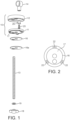
- Figure 1:
- shows an isometric exploded view of a combination of components which, together, form a toilet seat hinge according to the invention;
- Figure 2:
- shows a plan view of a contact surface included in the fixing member of
Figure 1 ; - Figures 3a to 3c:
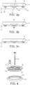
- show successive views of a contact surface being displaced into contact with a toilet pan;
- Figure 4:
- shows an exploded isometric view of a second unclaimed embodiment ofhinge;
- Figures 5a and 5b:
- show successive steps in securing the components of
Figure 4 to a toilet pan according to an unclaimed embodiment; and - Figures 6a and 6b
- show successive steps in the operation of a third embodiment of hinge that is not claimed.
- Referring to
Figures 1 to 3 , a first embodiment of toilet seat hinge according to the invention includes ahinge base 10 comprising afixing part 11 and acover 12, a threadedfixing bolt 13, and apillar 14. Thefixing part 11 is fixed to the upper surface of atoilet pan 15 by a bonding component adhesivised on both sides thereof, preferably a very high bond (VHB) doublesided tape 16, which adheres on one side to acontact surface 17 of thefixing part 11, and on the other side to thetoilet pan 15. A protective paper covering 16a is provided to cover the VHB tape on that surface that is to bond to the pan, prior to installation of the hinge. - At installation with the
fixing part 11 secured in position, thecover 12 is located over the fixing part and is secured in position by the threadedfixing bolt 13. In the conventional manner, thebolt 13 is engaged at one end in thecover 12, is passed through locating holes (not shown) in thepan 15, and is secured on the underside of the pan using anut 18 and washer 19. Tightening of thenut 18 clamps thecontact surface 17, with attachedVHB tape 16, against the toilet pan and thus ensures that a very secure connection is achieved between the hinge and the pan. - In the embodiment shown in
Figure 1 , the hinge is what is referred to in the trade as a bottom-fixing hinge. In the embodiment shown inFigures 4 &5 , the hinge is a top-fixing hinge. The invention described herein is applicable to both forms of hinge. - A characterising feature of the invention is that the hinge can be moved freely and located in the desired position relative to the pan, and then secured in position on the pan, without the need for any trial assembly. To this end a spacing facility is provided that is configured to space the
contact surface 17, and the VHB tape (withcover paper 16a removed therefrom) from the pan while the hinge base is positioned in the correct location. When in the correct location, the hinge base is displaced toward the pan, and the spacing facility is displaced or deformed until the VHB tape comes into contact with the pan. The displacing force applied to the hinge base may be applied manually and/or may be effected by tightening thenut 18. - Referring to the embodiment shown in
Figures 1 to 3 , the spacing facility is formed as an integral part of the hinge base and projects from the periphery of thecontact surface 17. As can be seen most clearly inFigure 2 , threeprojections 20 are spaced around the periphery of thecontact surface 17 and project outwardly from the plane of the surface. The projections are preferably equi-spaced around the periphery to provide the necessary support function, and each has a vee-shapedcentral formation 21 to assist deformation and/or fracturing. Underlying each of the projections is arecess 22. - As can be seen in
Figures 3a to 3c , when the hinge base is first located against thetoilet pan 15, and with theprotective covering 16a removed, theprojections 20 maintain the under-surface of the VHB tape clear of the pan. As can be seen inFigure 3c , with only theprojections 20 contacting the pan, thefixing part 11 may be displaced over the pan surface until the final fixing position is established. Thereafter, as shown inFigure 3c , a downward displacing force is applied to thefixing part 11 which causes the projections to distort and possibly to fracture. The distorted or fractured remnants of the protections are then received in therecesses 22. It will be appreciated that, as the projections distort or fracture, the VHB tape contacts the pan and bonds thefixing part 11 to thepan 15. - Referring now to
Figures 4 and5 , parts of a second unclaimed embodiment of hinge are shown, this embodiment including ahinge base 30, ahinge connector 31 projecting upwardly from the base, afixing bolt 32, and aspacer 33. Adisc 34 of VHB tape is fixed to the underside of thebase 30 and the underside of this disc is maintained out of contact with the surface of the toilet pan, while the base is positioned in the desired location relative to the pan. - In this particular embodiment the spacer comprises a ring having an inner
annular surface 35 that engages adownward spigot 36 forming part of thebase 30. Thespigot 36 may be a firm frictional fit within thespacer 33 or thesurfaces bolt 32, will overcome any resistance between the base 30 and thespacer 33, causing thespigot 36 to slide within the spacer until the VHB tape contacts and bonds to the surface of the pan.Figure 5a shows the base 30 in the raised position relative to thepan 15 whileFigure 5b shows the base 30 displaced so that the VHB tape is bonded to the pan. - Referring now to
Figures 6a and 6b , parts of a third embodiment that is not claimed are shown comprising ahinge base 40 for connection to asurface 15 of a toilet pan using adisc 41 of VHB tape. During positioning of the base 40 relative to thepan 15 the base is maintained clear of the pan by aspacer 42 which comprises abase plate 43 having a number ofspikes 44 projecting downwardly therefrom. Thebase 40 andVHB tape 41 are formed withholes 45 in positions that correspond to the positions ofspikes 44 and thus the spikes can be engaged through theholes 45 to engage thesurface 15 of the pan. It will be seen that the length of thespikes 44 is greater than the thickness of thebase 40 and thus with thespacer 42 fully engaged with the in the desired location, it may be displaced downwardly whereupon thespikes 44 dis-engage fromholes 45 and the VHB disc can engage and bond to thesurface 15 as shown inFig 6b . Thespacer 42 can then be removed completely. - Any suitable means can be provided to maintain the base 40 in the upward position shown in
Figure 6a , during positioning of thebase 40. For example thespikes 44 and holes 45 may be configured to provide friction between the two when in the position shown inFigure 6a . Other means such as engaging projections and recesses could be used and a further option would be to use a relatively low bond double-sided adhesive tape between the under side ofplate 43 and the upper side of thebase 40. - The embodiments described herein conveniently incorporate an adhesive in the form of a VHB tape, falling under the invention.
- Referring back to
Figure 1 , in another aspect the invention provides a novel and useful means of mounting thehinge pillar 14, to the hinge base and, in particular, to thecover 12. - When installing toilet seat hinges, the positions of
hinge fixings 11, covers 12 andpillars 14 must be manipulated to ensure that the seat is correctly located along fore and aft, and lateral, axes. Generally, changing the position of one component affects the positions of the others and so a trial installation is undertaken in which the components are loosely interconnected, the correct positions are established and noted, and the components then disassembled, tightened and fixed back in the established positions. The present invention proposes an apparatus which eliminate the need for pre-assembly and allow correct positioning of components, and secure fixing, from the outset. - In the foregoing we have described an unclaimed method for correct positioning and fixing of the hinge base relative to the pan. Further adjustment is required between the
pillar 14 and thecover 12. Previously, with the pillar directly attached to cover 12 using a fixingscrew 25 any rotation of the pillar relative to the cover, to establish correct positioning, would loosen the fixingscrew 25. Thus, once the correct positions had been established, thecover 12 would have to be removed and thescrew 25 retightened as part of final assembly. This problem is addressed in a further aspect of the invention by mountingpillar 14 on anintermediate mount 26 using fixingscrew 25. Theintermediate mount 25 is configured to be a firm rotating fit within thecover 12 and thus the pivotal position of thepillar 14 relative to the cover can be established without any loosening of the connection between the pillar and the cover. - It will thus be appreciated that the invention, as least in the case of the various embodiments described, allow toilet seat hinge components to be positioned and fixed to a toilet pan effectively and without significant, or possibly any, trial assembly.
Claims (7)
- A hinge for mounting a toilet seat on a toilet pan, said hinge including a hinge base (10) having a contact surface (17) engageable with said pan (15), wherein said contact surface has engaged therewith a bonding component (16) adhesivised on both sides thereof for fixing said contact surface (17) to said pan, said hinge including a spacing facility (20) configured to maintain a space between said bonding component (16) and said pan, said spacing facility (20) being deformable by the application of a force to said hinge base (10) against said pan to allow the bonding component to contact, and adhere said hinge to said pan, characterised in that said spacing facility (20) is formed integrally with said contact surface (17) and is configured to fracture upon displacement of said hinge base into contact with said pan and the hinge is further including a fixing rod (13) locatable through a hole in said pan.
- A hinge as claimed in claim 1 wherein said hinge base (10) comprises a fixing part (11) which includes said contact surface (17); and a cover (12) engageable over said fixing part.
- A hinge as claimed in claim 2 wherein said fixing part (11) further includes an aperture through which, in use, said fixing rod (13) may pass.
- A hinge as claimed in claim 1 wherein said bonding component (16) is formed from very high bond (VHB) tape.
- A hinge as claimed in claim 1 wherein said contact surface has apertures (22) to receive said spacing facility (20) as said hinge is displaced into contact with said pan (15).
- A hinge according to any previous claim further comprising a pillar (14) mounted to said hinge base for pivotal engagement with a toilet seat; and a fixing member (25) to fix said pillar (14) to said hinge base; said hinge being characterised in that an intermediate mount (26) is provided, said fixing member (25) fixing said pillar (14) to said intermediate mount (26) and said intermediate mount (26) being rotatably located in said hinge base (10).
- A hinge as claimed in claim 6 wherein said hinge base (10) includes a fixing part engageable with a toilet pan, and a cover engageable over said fixing part, said pillar (14) being mounted on said cover (12) by way of said intermediate mount.
Applications Claiming Priority (1)
| Application Number | Priority Date | Filing Date | Title |
|---|---|---|---|
| PCT/GB2017/050473 WO2018154261A1 (en) | 2017-02-23 | 2017-02-23 | Mounting method and/or apparatus for mounting a toilet seat |
Publications (3)
| Publication Number | Publication Date |
|---|---|
| EP3585227A1 EP3585227A1 (en) | 2020-01-01 |
| EP3585227B1 true EP3585227B1 (en) | 2024-11-13 |
| EP3585227C0 EP3585227C0 (en) | 2024-11-13 |
Family
ID=58228346
Family Applications (1)
| Application Number | Title | Priority Date | Filing Date |
|---|---|---|---|
| EP17708873.9A Active EP3585227B1 (en) | 2017-02-23 | 2017-02-23 | Mounting method and/or apparatus for mounting a toilet seat |
Country Status (4)
| Country | Link |
|---|---|
| US (2) | US20200008633A1 (en) |
| EP (1) | EP3585227B1 (en) |
| ES (1) | ES2994292T3 (en) |
| WO (1) | WO2018154261A1 (en) |
Families Citing this family (3)
| Publication number | Priority date | Publication date | Assignee | Title |
|---|---|---|---|---|
| GB2573540B (en) * | 2018-05-09 | 2021-04-07 | Norcros Group Holdings Ltd | Mounting method and apparatus |
| DE102020107947A1 (en) * | 2020-03-23 | 2021-09-23 | Hamberger Industriewerke Gmbh | Fastening device |
| US11987967B1 (en) * | 2023-06-05 | 2024-05-21 | Patrick Gerard Stack | High efficiency toilet |
Family Cites Families (8)
| Publication number | Priority date | Publication date | Assignee | Title |
|---|---|---|---|---|
| DK176340B1 (en) * | 2004-07-12 | 2007-08-27 | Pressalit Group As | Adjustable toilet hinge bracket |
| US8310369B1 (en) * | 2009-03-27 | 2012-11-13 | Nth Solutions, Llc | Detecting unintended flush toilet water flow |
| GB2511790B (en) * | 2013-03-13 | 2018-03-14 | Croydex Ltd | Toilet seat mounting method and apparatus |
| DE202013102982U1 (en) * | 2013-04-09 | 2014-07-14 | Glabete Gmbh | Magnetic system kit and equipment series |
| CN203576408U (en) * | 2013-10-31 | 2014-05-07 | 彭东 | Support assembly for connecting closestool cover plate with closestool base |
| CN104095581B (en) * | 2014-07-18 | 2016-01-27 | 厦门豪帝卫浴工业有限公司 | The easy-to-dismount water-closet bowl cover plate of one seed holder circle |
| CN204105870U (en) * | 2014-09-01 | 2015-01-21 | 彭东 | There is the toilet support of positioning function |
| CN204971084U (en) * | 2015-08-17 | 2016-01-20 | 乐特瑞(厦门)卫浴有限公司 | One -button type closestool cover plate fast demounting and mounting device |
-
2017
- 2017-02-23 ES ES17708873T patent/ES2994292T3/en active Active
- 2017-02-23 EP EP17708873.9A patent/EP3585227B1/en active Active
- 2017-02-23 WO PCT/GB2017/050473 patent/WO2018154261A1/en not_active Ceased
- 2017-02-23 US US16/488,066 patent/US20200008633A1/en not_active Abandoned
-
2021
- 2021-03-12 US US17/199,634 patent/US11589718B2/en active Active
Also Published As
| Publication number | Publication date |
|---|---|
| ES2994292T3 (en) | 2025-01-21 |
| WO2018154261A1 (en) | 2018-08-30 |
| US11589718B2 (en) | 2023-02-28 |
| US20200008633A1 (en) | 2020-01-09 |
| EP3585227A1 (en) | 2020-01-01 |
| US20210196089A1 (en) | 2021-07-01 |
| EP3585227C0 (en) | 2024-11-13 |
Similar Documents
| Publication | Publication Date | Title |
|---|---|---|
| US11589718B2 (en) | Mounting method and/or apparatus for mounting a toilet seat | |
| US7581913B2 (en) | Seal nut assembly and method of manufacture | |
| CN102102696B (en) | Nuts with ear flares | |
| EP1760333A1 (en) | Female member of a fastening device, flush with a hole in a plate | |
| JP6816050B2 (en) | Bracket for fixing electronic devices and fixed structure for electronic devices | |
| GB2546799A (en) | Mounting method and apparatus | |
| DE10113044C2 (en) | System for fastening a component to a carrier component | |
| DE102012218168B3 (en) | Glass door hinge has stop screws that are screwed into two adjusting screw holes and are pressed against fastening portions so that fastening portions and contact surfaces are frictionally connected together | |
| AU2014229812B2 (en) | Mounting method and apparatus | |
| JP2018526187A (en) | Beverage press and method | |
| JP4720841B2 (en) | Washer fixing jig with tongue | |
| GB2573540A (en) | Mounting method and apparatus | |
| GB2592823A (en) | Toilet seat mounting apparatus | |
| EP1918445A1 (en) | Tub with ballast weight for a washing machine | |
| EP1918444B1 (en) | Waschine machine tub with ballast weight | |
| JP2008267564A (en) | Apparatus mounting device | |
| KR20240073743A (en) | Mounting member for grooved column material and fastener thereof | |
| JP6446720B2 (en) | Shelf mounting member | |
| KR200312772Y1 (en) | Apparatus for adjusting the position of a bolting hall | |
| DE60009401T2 (en) | Device for fixing a heat shield for an oil pump | |
| EP4491889A1 (en) | Blind fastening device for attaching a piece to a basic piece | |
| US20040151411A1 (en) | Swivel bearing | |
| EP4074988B1 (en) | Connection system and method of connecting | |
| JPH0640334Y2 (en) | Bolt / nut locking device | |
| JP6270355B2 (en) | Structural fasteners |
Legal Events
| Date | Code | Title | Description |
|---|---|---|---|
| STAA | Information on the status of an ep patent application or granted ep patent |
Free format text: STATUS: UNKNOWN |
|
| STAA | Information on the status of an ep patent application or granted ep patent |
Free format text: STATUS: THE INTERNATIONAL PUBLICATION HAS BEEN MADE |
|
| PUAI | Public reference made under article 153(3) epc to a published international application that has entered the european phase |
Free format text: ORIGINAL CODE: 0009012 |
|
| STAA | Information on the status of an ep patent application or granted ep patent |
Free format text: STATUS: REQUEST FOR EXAMINATION WAS MADE |
|
| 17P | Request for examination filed |
Effective date: 20190912 |
|
| AK | Designated contracting states |
Kind code of ref document: A1 Designated state(s): AL AT BE BG CH CY CZ DE DK EE ES FI FR GB GR HR HU IE IS IT LI LT LU LV MC MK MT NL NO PL PT RO RS SE SI SK SM TR |
|
| AX | Request for extension of the european patent |
Extension state: BA ME |
|
| DAV | Request for validation of the european patent (deleted) | ||
| DAX | Request for extension of the european patent (deleted) | ||
| STAA | Information on the status of an ep patent application or granted ep patent |
Free format text: STATUS: EXAMINATION IS IN PROGRESS |
|
| 17Q | First examination report despatched |
Effective date: 20220221 |
|
| GRAP | Despatch of communication of intention to grant a patent |
Free format text: ORIGINAL CODE: EPIDOSNIGR1 |
|
| STAA | Information on the status of an ep patent application or granted ep patent |
Free format text: STATUS: GRANT OF PATENT IS INTENDED |
|
| INTG | Intention to grant announced |
Effective date: 20240620 |
|
| GRAS | Grant fee paid |
Free format text: ORIGINAL CODE: EPIDOSNIGR3 |
|
| GRAA | (expected) grant |
Free format text: ORIGINAL CODE: 0009210 |
|
| STAA | Information on the status of an ep patent application or granted ep patent |
Free format text: STATUS: THE PATENT HAS BEEN GRANTED |
|
| AK | Designated contracting states |
Kind code of ref document: B1 Designated state(s): AL AT BE BG CH CY CZ DE DK EE ES FI FR GB GR HR HU IE IS IT LI LT LU LV MC MK MT NL NO PL PT RO RS SE SI SK SM TR |
|
| REG | Reference to a national code |
Ref country code: GB Ref legal event code: FG4D |
|
| REG | Reference to a national code |
Ref country code: CH Ref legal event code: EP |
|
| REG | Reference to a national code |
Ref country code: DE Ref legal event code: R096 Ref document number: 602017086081 Country of ref document: DE |
|
| REG | Reference to a national code |
Ref country code: IE Ref legal event code: FG4D |
|
| U01 | Request for unitary effect filed |
Effective date: 20241125 |
|
| U07 | Unitary effect registered |
Designated state(s): AT BE BG DE DK EE FI FR IT LT LU LV MT NL PT RO SE SI Effective date: 20241202 |
|
| REG | Reference to a national code |
Ref country code: ES Ref legal event code: FG2A Ref document number: 2994292 Country of ref document: ES Kind code of ref document: T3 Effective date: 20250121 |
|
| U20 | Renewal fee for the european patent with unitary effect paid |
Year of fee payment: 9 Effective date: 20250122 |
|
| PG25 | Lapsed in a contracting state [announced via postgrant information from national office to epo] |
Ref country code: HR Free format text: LAPSE BECAUSE OF FAILURE TO SUBMIT A TRANSLATION OF THE DESCRIPTION OR TO PAY THE FEE WITHIN THE PRESCRIBED TIME-LIMIT Effective date: 20241113 Ref country code: IS Free format text: LAPSE BECAUSE OF FAILURE TO SUBMIT A TRANSLATION OF THE DESCRIPTION OR TO PAY THE FEE WITHIN THE PRESCRIBED TIME-LIMIT Effective date: 20250313 |
|
| PG25 | Lapsed in a contracting state [announced via postgrant information from national office to epo] |
Ref country code: NO Free format text: LAPSE BECAUSE OF FAILURE TO SUBMIT A TRANSLATION OF THE DESCRIPTION OR TO PAY THE FEE WITHIN THE PRESCRIBED TIME-LIMIT Effective date: 20250213 |
|
| PG25 | Lapsed in a contracting state [announced via postgrant information from national office to epo] |
Ref country code: GR Free format text: LAPSE BECAUSE OF FAILURE TO SUBMIT A TRANSLATION OF THE DESCRIPTION OR TO PAY THE FEE WITHIN THE PRESCRIBED TIME-LIMIT Effective date: 20250214 |
|
| PG25 | Lapsed in a contracting state [announced via postgrant information from national office to epo] |
Ref country code: PL Free format text: LAPSE BECAUSE OF FAILURE TO SUBMIT A TRANSLATION OF THE DESCRIPTION OR TO PAY THE FEE WITHIN THE PRESCRIBED TIME-LIMIT Effective date: 20241113 |
|
| PG25 | Lapsed in a contracting state [announced via postgrant information from national office to epo] |
Ref country code: RS Free format text: LAPSE BECAUSE OF FAILURE TO SUBMIT A TRANSLATION OF THE DESCRIPTION OR TO PAY THE FEE WITHIN THE PRESCRIBED TIME-LIMIT Effective date: 20250213 |
|
| PG25 | Lapsed in a contracting state [announced via postgrant information from national office to epo] |
Ref country code: SM Free format text: LAPSE BECAUSE OF FAILURE TO SUBMIT A TRANSLATION OF THE DESCRIPTION OR TO PAY THE FEE WITHIN THE PRESCRIBED TIME-LIMIT Effective date: 20241113 |
|
| PG25 | Lapsed in a contracting state [announced via postgrant information from national office to epo] |
Ref country code: SK Free format text: LAPSE BECAUSE OF FAILURE TO SUBMIT A TRANSLATION OF THE DESCRIPTION OR TO PAY THE FEE WITHIN THE PRESCRIBED TIME-LIMIT Effective date: 20241113 |
|
| PG25 | Lapsed in a contracting state [announced via postgrant information from national office to epo] |
Ref country code: CZ Free format text: LAPSE BECAUSE OF FAILURE TO SUBMIT A TRANSLATION OF THE DESCRIPTION OR TO PAY THE FEE WITHIN THE PRESCRIBED TIME-LIMIT Effective date: 20241113 |
|
| PG25 | Lapsed in a contracting state [announced via postgrant information from national office to epo] |
Ref country code: MC Free format text: LAPSE BECAUSE OF FAILURE TO SUBMIT A TRANSLATION OF THE DESCRIPTION OR TO PAY THE FEE WITHIN THE PRESCRIBED TIME-LIMIT Effective date: 20241113 |
|
| PLBE | No opposition filed within time limit |
Free format text: ORIGINAL CODE: 0009261 |
|
| STAA | Information on the status of an ep patent application or granted ep patent |
Free format text: STATUS: NO OPPOSITION FILED WITHIN TIME LIMIT |
|
| REG | Reference to a national code |
Ref country code: CH Ref legal event code: PL |
|
| PG25 | Lapsed in a contracting state [announced via postgrant information from national office to epo] |
Ref country code: CH Free format text: LAPSE BECAUSE OF NON-PAYMENT OF DUE FEES Effective date: 20250228 |
|
| 26N | No opposition filed |
Effective date: 20250814 |
|
| GBPC | Gb: european patent ceased through non-payment of renewal fee |
Effective date: 20250223 |
|
| PG25 | Lapsed in a contracting state [announced via postgrant information from national office to epo] |
Ref country code: GB Free format text: LAPSE BECAUSE OF NON-PAYMENT OF DUE FEES Effective date: 20250223 |
|
| U20 | Renewal fee for the european patent with unitary effect paid |
Year of fee payment: 10 Effective date: 20260119 |
|
| PGFP | Annual fee paid to national office [announced via postgrant information from national office to epo] |
Ref country code: ES Payment date: 20260311 Year of fee payment: 10 |
|
| PGFP | Annual fee paid to national office [announced via postgrant information from national office to epo] |
Ref country code: IE Payment date: 20260123 Year of fee payment: 10 |