EP3585173B1 - Machine for making filled pasta - Google Patents
Machine for making filled pasta Download PDFInfo
- Publication number
- EP3585173B1 EP3585173B1 EP18712457.3A EP18712457A EP3585173B1 EP 3585173 B1 EP3585173 B1 EP 3585173B1 EP 18712457 A EP18712457 A EP 18712457A EP 3585173 B1 EP3585173 B1 EP 3585173B1
- Authority
- EP
- European Patent Office
- Prior art keywords
- roller
- dough
- layers
- cutting
- moulds
- Prior art date
- Legal status (The legal status is an assumption and is not a legal conclusion. Google has not performed a legal analysis and makes no representation as to the accuracy of the status listed.)
- Active
Links
Images



Classifications
-
- A—HUMAN NECESSITIES
- A21—BAKING; EDIBLE DOUGHS
- A21C—MACHINES OR EQUIPMENT FOR MAKING OR PROCESSING DOUGHS; HANDLING BAKED ARTICLES MADE FROM DOUGH
- A21C9/00—Other apparatus for handling dough or dough pieces
- A21C9/06—Apparatus for filling pieces of dough such as doughnuts
- A21C9/066—Apparatus for filling pieces of dough such as doughnuts using two separate sheets or pieces of dough with filling in between, e.g. crimped at their edges; Ravioli-making machines
-
- A—HUMAN NECESSITIES
- A21—BAKING; EDIBLE DOUGHS
- A21C—MACHINES OR EQUIPMENT FOR MAKING OR PROCESSING DOUGHS; HANDLING BAKED ARTICLES MADE FROM DOUGH
- A21C11/00—Other machines for forming the dough into its final shape before cooking or baking
- A21C11/02—Embossing machines
- A21C11/04—Embossing machines with cutting and embossing rollers or drums
-
- A—HUMAN NECESSITIES
- A21—BAKING; EDIBLE DOUGHS
- A21C—MACHINES OR EQUIPMENT FOR MAKING OR PROCESSING DOUGHS; HANDLING BAKED ARTICLES MADE FROM DOUGH
- A21C11/00—Other machines for forming the dough into its final shape before cooking or baking
- A21C11/02—Embossing machines
- A21C11/06—Embossing machines handling regularly pre-shaped sheets of dough
-
- A—HUMAN NECESSITIES
- A21—BAKING; EDIBLE DOUGHS
- A21C—MACHINES OR EQUIPMENT FOR MAKING OR PROCESSING DOUGHS; HANDLING BAKED ARTICLES MADE FROM DOUGH
- A21C9/00—Other apparatus for handling dough or dough pieces
- A21C9/08—Depositing, arranging and conveying apparatus for handling pieces, e.g. sheets of dough
-
- A—HUMAN NECESSITIES
- A23—FOODS OR FOODSTUFFS; TREATMENT THEREOF, NOT COVERED BY OTHER CLASSES
- A23L—FOODS, FOODSTUFFS OR NON-ALCOHOLIC BEVERAGES, NOT OTHERWISE PROVIDED FOR; PREPARATION OR TREATMENT THEREOF
- A23L7/00—Cereal-derived products; Malt products; Preparation or treatment thereof
- A23L7/10—Cereal-derived products
- A23L7/109—Types of pasta, e.g. macaroni or noodles
- A23L7/11—Filled, stuffed or multilayered pasta
Definitions
- This invention relates to a machine for making filled pasta.
- filled pasta is used to mean a type of pasta consisting of one or more layers of dough stuffed with a filling of meat, fish, vegetable or cheese.
- ravioli is a filled pasta product of circular shape having, on each side of the dough layer, a respective bulge formed by the filling and also known as "belly" in the jargon of the trade.
- filled pasta is made by automatic machines.
- the moulds for shaping the respective first and second layers of dough allow easy changing over between different types of filled pasta products and facilitate maintenance operations on the shaping device itself.
- the reference numeral 1 denotes a machine for making filled pasta products.
- the filled pasta products 2 of this specification comprise two layers of pasta dough 7, 8, specifically a first dough layer 7 and a second dough layer 8 enclosing between them a filling 4, for example based on meat, fish, vegetables or cheese.
- the dough layers 7, 8 of the filled pasta products 2 are superposed and sealed to each other along a common joining zone 6 in order to prevent the filling 4 from escaping.
- the filled pasta products 2 of this specification have, on each side defined by the first and the second dough layer 7 and 8, a respective bulge 5, known as "belly" in the jargon of the trade, formed by the filling 4 under the respective dough layer 7 and 8.
- the filled pasta product 2 of this specification is known by the term "ravioli". More specifically, the ravioli of the specification is disc-shaped and thus, the joining zone 6 where the dough layers 7 and 8 are sealed to each other has the shape of a circular crown 6 surrounding the filling 4.
- the machine 1 of this specification comprises a first feeding device 9 for feeding a first layer 7 of pasta dough and a second feeding device 10 for feeding a second layer 8 of pasta dough.
- a shaping device 11 for shaping the filled pasta products 2 is located downstream of the first and second feeding devices 9 and 10, with reference to the direction of unrolling the first and second layers 7 and 8 of pasta dough.
- the shaping device 11 is configured to advance the first and second layers 7 and 8 of pasta dough and, while it advances them, to shape the dough layers 7 and 8 in such a way that they can receive the filling 4, and to press them against each other in order to define the joining zone 6 where the first and second dough layers 7 and 8 are sealed to each other around the filling 4.
- the shaping device 11 is configured to cut the first and second dough layers 7 and 8, individually separating each filled pasta product 2 from the dough layers 7 and 8 as they advance in the device 11.
- the filled pasta products 2 are transported by a conveyor line 14 for further processing in other production machines.
- the shaping device 11 of the machine 1 comprises a first and a second roller 23 and 24 for advancing and shaping the first and the second layer 7 and 8, respectively.
- the first and second rollers 23 and 24 rotate about respective axes of rotation 23a and 24a.
- the axes of rotation 23a and 24a of the rollers 23 are 24 are parallel to each other.
- the first and the second roller 23 and 24 are disposed to face and be tangent to each other at a coupling station 26 for coupling the first and the second layer 7, 8 around the respective filling 4.
- the first and the second roller 23 and 24 of the shaping device 11 each have on the peripheral surface respective moulds 23b and 24b which are configured to shape the respective dough layer 7, 8 so that they can receive the filling 4.
- the moulds 23b and 24b of the first and the second roller 23, and 24 comprise respective hollows 37, 38, concave relative to the respective peripheral outside surface of the first and second rollers 23 and 24, for receiving the respective layers of dough 7 and 8.
- the concave peripheral surface of the hollows 37 and 38 of the first and second rollers 23 and 24, which act in conjunction at the coupling station 26 for coupling the first and the second layer 7 and 8, allow shaping a respective bulge 5 of the filled pasta 2.
- the moulds 23b and 24b of the first and the second roller 23, and 24 comprise respective pressing zones 53 and 54 surrounding the respective hollows 37 and 38.
- the pressing zones 53 and 54 of the respective moulds 23b and 24b of the first and the second roller 23, and 24 acting in conjunction at the coupling station 26 allow joining the first and the second layer 7 and 8 to each other to define the joining 6 on the product 2 where the pasta is sealed.
- the moulds 23b on the first roller 23 are disposed along respective rows 28, each extending along a direction parallel to the axis of rotation 23a of the first roller 23.
- the rows 28 of moulds 23b are equispaced from each other.
- the moulds 24b on the second roller 24 are disposed along respective rows 31, each extending along a direction parallel to the axis of rotation 24b of the second roller 24.
- the rows 31 of moulds 24b are equispaced from each other.
- the shaping device 11 comprises dispensing means 27 for delivering the filling 4 to the first and second layers 7 and 8 as the first and second rollers 23 and 24 advance them to the coupling station 26.
- the dispensing means 27 for delivering the filling 4 are disposed between the first and the second roller 23 and 24.
- the dispensing means 27 for delivering the filling 4 are configured to feed the filling 4 to the moulds 23b and 24b of the first and second rollers 23 and 24 which face each other at the coupling station 26 for coupling the first and second layers 7 and 8.
- the dispensing means 27 comprise a plurality of dispensing nozzles 44 for delivering the filling 4.
- Each nozzle 44 is configured to deliver the filling 4 to a respective pair of moulds 23b and 24b of the first and second rollers 23 and 24 which face each other at the coupling station 26 for coupling the first and second layers 7 and 8.
- the number of nozzles 44 of the dispensing means 27 is equal to the number of moulds 23b and 24b disposed along each row 28, 31 on the first and second rollers 23 and 24.
- Each nozzle 44 is configured to move towards and away from the respective pair of moulds 23b and 24b of the first and second rollers 23 and 24 which face each other at the coupling station 26 for coupling the first and second layers 7 and 8.
- the shaping device 11 of the machine 1 comprises suction means 32 which are in fluid communication with the first and the second roller 23 and 24.
- the suction means 32 are in fluid communication with the hollows 37 and 38 for receiving the first and second layers 7 and 8 on the first and second rollers 23 and 24.
- the receiving hollows 37 of the first roller 23 have respective air inlet mouths 41 in fluid communication with the suction means 32.
- the receiving hollows 38 of the second roller 24 have respective air inlet mouths 42 in fluid communication with the suction means 32.
- the suction means 32 are configured to operate at least at the moulds 23b and 24b of the first and second rollers 23 and 24 in transit through the coupling station 26 for coupling the first and second layers 7 and 8 around the filling 4.
- the suction means 32 cause the first and the second layer 7 and 8 to adhere to the surface of the respective moulds 23b and 24b, adopting the shape thereof so as to make it easier for them to receive the filling 4.
- the shaping device 11 of the machine 1 comprises blowing means 33.
- blowing means 33 are in fluid communication with the hollows 37 and 38 for receiving the first and second layers 7 and 8 on the first and second rollers 23 and 24.
- the mouths 41 of the receiving hollows 37 of the first roller 23 are in fluid communication with the blowing means 33 to let air out.
- the mouths 42 of the receiving hollows 38 of the second roller 24 are in fluid communication with the blowing means 33 to let air out.
- blowing means 33 cause the first and the second layer 7 and 8 to come away to the surface of the respective moulds 23b and 24b and to be wrapped around the respective filling 4, facilitating its detachment from the dispensing means 27.
- the machine 1 comprises a control unit 43 configured to control the switching on and off of the suction means 32.
- the control unit 43 is configured to control the switching on and off of the blowing means 33.
- the control unit 43 is configured to switch on the suction means 32 during transit of the moulds 23b and 24b of the first and second rollers 23 and 24 in the coupling station 26.
- control unit 43 is configured to switch on the suction means 32 before the dispensing means 27 release the filling 4 into the moulds 23b and 24b of the first and second rollers 23 and 24 in transit in the coupling station 26.
- first and the second layer 7 and 8 are shaped by the respective moulds 23b and 24b to receive the filling 4.
- control unit 43 is configured to switch off the suction means 32 once the dispensing means 27 have released the filling 4 into the respective moulds 23b and 24b.
- control unit 43 switches on the blowing means 33 in such a way that the first and second layers 7 and 8 come away to the surface of the respective moulds 23b and 24b and are wrapped around the respective filling 4, facilitating its detachment from the dispensing means 27.
- control unit 43 is configured to switch on the suction means 32 at the same time as the dispensing means 27 release the filling 4 into the moulds 23b and 24b of the first and second rollers 23 and 24 in transit in the coupling station 26.
- This operating mode allows creating a light vacuum in the hollows 37 and 38 of the moulds 23b and 24b to facilitate delivery of the filling 4 from the dispensing means 27.
- the control unit 43 is configured to be programmed by an operator to set the operating mode as a function of the physical properties of the filling 4.
- the shaping device 11 comprises a cutting roller 25 acting in conjunction with one of either the first roller 23 or the second roller 24, specifically with the second roller 24, in order to individually separate each product 2 from the first and the second layer 7 and 8 of dough.
- the cutting roller 25 and the roller 24 of the shaping device it acts in conjunction with, in particular the second roller 24, are tangent to each other at a cutting station 35 where each product 2 is separated from the first and the second layer 7 and 8 of dough.
- the cutting roller 25 releases the filled pasta 2 onto the conveyor line 14 at a release station 40.
- the cutting roller 25 rotates about its axis of rotation 25a.
- the axis of rotation 25a of the cutting roller 25 is parallel to the axes of rotation 23a and 24a of the advancing and shaping rollers 23, 24.
- the cutting roller 25 On the peripheral surface of it, the cutting roller 25 has respective cutting edges 25b shaped to cut the dough layers 7, 8 at their sealing zone 6.
- the cutting edges 25 are shaped to match the moulds 24b of the roller 24 of the shaping device 11 it acts in conjunction with, relative in particular to the moulds 24b of the second roller 24, in such a way as to oppose them along the perimeter of the pressing zone 54 of the respective mould 24b.
- the cutting edge 25b of the cutting roller 25 operates at the periphery of the sealed pasta zone 6 of the product 2 without cutting other portions of the first and second layers 7 and 8 outside the mould 24b of the second roller 24.
- the offcuts of the first layer 7 and the offcuts of the second layer 8 can be advanced separately because they are not sealed to each other.
- the possibility of recovering the offcuts 7a of the first dough layer 7 separately from the offcuts 8a of the second dough layer 8 allows using layers 7 and 8 made of dough having different properties, such as doughs of different colours, for example.
- the machine 1 Downstream of the cutting roller 25, the machine 1 comprises a conveying line 55 for the offcuts 7a of the first dough layer 7 and a separate conveying line 56 for the offcuts 8a of the second dough layer 8.
- the cutting edges 25b of the cutting roller 25 are disposed along respective rows 34, each extending along a direction parallel to the axis of rotation 25a of the cutting roller 25.
- the rows 34 of cutting edges 25b are equispaced from each other.
- the cutting roller 25 of the machine 1 according to this invention has, on the peripheral outside surface of it, a plurality of hollows 36, each of which is adapted to receive a respective product 2.
- Each hollow 36 is surrounded by a respective shaped cutting edge 25b.
- Each hollow 36 of the cutting roller 25 is concave relative to the peripheral outside surface of the cutting roller 25 so that the surface of the hollow 36 can receive the bulge 5 of the filled pasta 2, defined by the filling 4 under the dough layer 3.
- Each hollow 36 of the cutting roller 25 has at least one air suction or blowing mouth 39 configured to be in fluid communication with the suction means 32 and with the blowing means 33 as a function of the position of the hollow 32 during the rotation of the cutting roller 25.
- each hollow 36 of the cutting roller 25 is in fluid communication with the suction means 32 so that each hollow 36 receives the respective product 2, separated from the first and second layer 7 and 8, and then releases it onto the conveyor line 14.
- each hollow 36 of the cutting roller 25 holds the respective product 2 by suction thanks to the fluid connection between the respective mouth 39 and the suction means 32.
- the mouth 39 of each hollow 36 of the cutting roller 25 is in fluid communication with the blowing means 33 so as to expel the product 2 from the hollow 36.
- the cutting roller 25 of the machine 1 allows handling the product 2 in accurately and precisely in terms of its position and centring, thus increasing the quality of the filled pasta 2 made by the machine 1.
- the first roller 23 and the second roller 24 comprise a respective supporting roller 45, 46 on which the moulds 23b and 24b of the first roller 23 and second roller 24 can be mounted.
- the moulds 23b and 24b of the first roller 23 and second roller 24 are configured to be assembled and disassembled to and from the supporting roller 45 and 46 of the first and the second roller 23 and 24.
- the possibility of assembling and disassembling the moulds 23b and 24b of the first roller 23 and second roller 24 allows the supporting rollers 45 and 46 of the first and the second roller 23 and 24 to be used for two or more sizes of filled pasta 2.
- the supporting roller 45 of the first roller 23 has a plurality of grooves 47 defining means for conveying air out of the suction means 32 or out of the blowing means 33.
- each groove 47 extends in a direction parallel to the axis of rotation 23a of the first roller 23 and is configured to convey the air to a respective row 28 of moulds 23b.
- the mouths 41 of the hollows 37 of the first roller 23, once assembled to the supporting roller 45, are in fluid communication with the respective groove 47.
- the supporting roller 45 of the first roller 23 has a plurality of grooves 47 which are equispaced from each other along the peripheral surface of the supporting roller 45 of the first roller 23.
- the supporting roller 46 of the second roller 24 has a plurality of grooves 48 defining means for conveying air out of the suction means 32 or out of the blowing means 33.
- each groove 48 extends in a direction parallel to the axis of rotation 24a of the second roller 24 and is configured to convey the air to a respective row 31 of moulds 24b.
- the supporting roller 46 of the second roller 24 has a plurality of grooves 48 which are equispaced from each other along the peripheral surface of the supporting roller 46 of the second roller 24.
- the grooves 47, 48 made on the respective supporting roller make it easier to clean the first and second rollers 23 and 24, thus limiting maintenance times and costs.
- the cutting roller 25 comprises a respective supporting roller 49 on which the cutting edges 25b can be mounted.
- Each of the cutting edges 25b of the cutting roller 25 is supported by a respective block 50 configured to be assembled and disassembled to and from the supporting roller 49 of the cutting roller 25.
- the possibility of assembling and disassembling the blocks 50 supporting the cutting edges 25b of the cutting roller 25 allows the supporting roller 49 of the cutting roller 25 to be used for two or more sizes of filled pasta 2.
- the possibility of assembling and disassembling the blocks 50 supporting the cutting edges 25b of the cutting roller 25 allows replacing worn, faulty or chipped cutting edges 25b without having to replace the entire cutting roller 25.
- the supporting roller 49 of the cutting roller 25 has a plurality of grooves 51 defining means for conveying air out of the suction means 32 or out of the blowing means 33.
- each groove 51 extends in a direction parallel to the axis of rotation 25a of the cutting roller 25 and is configured to convey the air to a respective row 34 of moulds 36.
- the mouths 39 of the hollows 36 of the cutting roller 25, once assembled to the supporting roller 49, are in fluid communication with the respective groove 51.
- the supporting roller 49 of the cutting roller 25 has a plurality of grooves 51 which are equispaced from each other along the peripheral surface of the supporting roller 49 of the cutting roller 25.
- the grooves 51 made on the supporting roller 49 of the cutting roller 25 facilitate cleaning operations, thus limiting maintenance times and costs.
- the shaping device is extractable from the supporting frame 52 it is mounted on.
Landscapes
- Life Sciences & Earth Sciences (AREA)
- Engineering & Computer Science (AREA)
- Food Science & Technology (AREA)
- Manufacturing And Processing Devices For Dough (AREA)
- Noodles (AREA)
- Formation And Processing Of Food Products (AREA)
- Bakery Products And Manufacturing Methods Therefor (AREA)
Description
- This invention relates to a machine for making filled pasta.
- The term "filled pasta" is used to mean a type of pasta consisting of one or more layers of dough stuffed with a filling of meat, fish, vegetable or cheese.
- For example, ravioli is a filled pasta product of circular shape having, on each side of the dough layer, a respective bulge formed by the filling and also known as "belly" in the jargon of the trade.
- To be able to supply it to large-scale distributors, filled pasta is made by automatic machines.
- Prior art automatic machines, however, do not allow changeovers to be carried out quickly and cleaning operations to remove dough residues are slow and painstaking, if not impossible, and involve lengthy machine down times.
- A known machine is illustrated and described in document
EP2092828 A2 . DocumentsUS2003024360 A1 ,WO2012107236 A2 andUS4941402 A disclose different machines for handling dough. - The invention is defined in the claims. The aforementioned drawbacks are overcome by a machine according to claim 1. The dependent claims define optional embodiments of the invention.
- According to the invention, since they are configured to be assembled to and disassembled from respective supporting rollers, the moulds for shaping the respective first and second layers of dough allow easy changing over between different types of filled pasta products and facilitate maintenance operations on the shaping device itself.
- Further features and advantages of the invention are more apparent in the description which follows, of embodiments of a machine according to the invention for making filled pasta as illustrated in the accompanying drawings, in which:
-
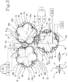
Figure 1 shows a schematic front view of the machine for making filled pasta according to this invention; -
Figure 2 is a scaled-up, schematic front view of a detail fromFigure 1 ; -
Figure 3 is a scaled-up schematic perspective view of a detail fromFigures 1 and2 ; -
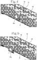
Figures 4 and 5 are schematic perspective views of a detail fromFigure 3 ; -
Figures 6 and 7 are schematic perspective views illustrating the mode of assembling and removing the shaping device of the machine according to this invention. - The reference numeral 1 denotes a machine for making filled pasta products.
- The filled
pasta products 2 of this specification comprise two layers ofpasta dough first dough layer 7 and asecond dough layer 8 enclosing between them a filling 4, for example based on meat, fish, vegetables or cheese. - The
dough layers pasta products 2 are superposed and sealed to each other along acommon joining zone 6 in order to prevent thefilling 4 from escaping. - The filled
pasta products 2 of this specification have, on each side defined by the first and thesecond dough layer respective bulge 5, known as "belly" in the jargon of the trade, formed by thefilling 4 under therespective dough layer - The filled
pasta product 2 of this specification is known by the term "ravioli". More specifically, the ravioli of the specification is disc-shaped and thus, the joiningzone 6 where thedough layers circular crown 6 surrounding thefilling 4. - The machine 1 of this specification comprises a
first feeding device 9 for feeding afirst layer 7 of pasta dough and asecond feeding device 10 for feeding asecond layer 8 of pasta dough. - A
shaping device 11 for shaping the filledpasta products 2 is located downstream of the first andsecond feeding devices second layers - The
shaping device 11 is configured to advance the first andsecond layers dough layers filling 4, and to press them against each other in order to define the joiningzone 6 where the first andsecond dough layers filling 4. - The
shaping device 11 is configured to cut the first andsecond dough layers pasta product 2 from thedough layers device 11. - Downstream of the
shaping device 11, the filledpasta products 2 are transported by aconveyor line 14 for further processing in other production machines. - The
shaping device 11 of the machine 1 comprises a first and asecond roller second layer - The first and
second rollers rotation - The axes of
rotation rollers 23 are 24 are parallel to each other. - The first and the
second roller coupling station 26 for coupling the first and thesecond layer respective filling 4. - The first and the
second roller shaping device 11 each have on the peripheral surfacerespective moulds respective dough layer filling 4. - The
moulds second roller respective hollows second rollers dough - The concave peripheral surface of the
hollows second rollers coupling station 26 for coupling the first and thesecond layer respective bulge 5 of the filledpasta 2. - The
moulds second roller pressing zones respective hollows - The
pressing zones respective moulds second roller coupling station 26 allow joining the first and thesecond layer product 2 where the pasta is sealed. - The
moulds 23b on thefirst roller 23 are disposed alongrespective rows 28, each extending along a direction parallel to the axis ofrotation 23a of thefirst roller 23. - With reference to the outside surface of the
first roller 23, therows 28 ofmoulds 23b are equispaced from each other. - The
moulds 24b on thesecond roller 24 are disposed alongrespective rows 31, each extending along a direction parallel to the axis ofrotation 24b of thesecond roller 24. - With reference to the outside surface of the
second roller 24, therows 31 ofmoulds 24b are equispaced from each other. - The
shaping device 11 comprises dispensing means 27 for delivering thefilling 4 to the first andsecond layers second rollers coupling station 26. - The dispensing means 27 for delivering the
filling 4 are disposed between the first and thesecond roller - More specifically, the dispensing means 27 for delivering the
filling 4 are configured to feed thefilling 4 to themoulds second rollers coupling station 26 for coupling the first andsecond layers - The dispensing means 27 comprise a plurality of dispensing
nozzles 44 for delivering thefilling 4. - Each
nozzle 44 is configured to deliver thefilling 4 to a respective pair ofmoulds second rollers coupling station 26 for coupling the first andsecond layers - The number of
nozzles 44 of the dispensing means 27 is equal to the number ofmoulds row second rollers - Each
nozzle 44 is configured to move towards and away from the respective pair ofmoulds second rollers coupling station 26 for coupling the first andsecond layers - The
shaping device 11 of the machine 1 comprises suction means 32 which are in fluid communication with the first and thesecond roller - More specifically, the suction means 32 are in fluid communication with the
hollows second layers second rollers - The receiving
hollows 37 of thefirst roller 23 have respectiveair inlet mouths 41 in fluid communication with the suction means 32. - The receiving
hollows 38 of thesecond roller 24 have respectiveair inlet mouths 42 in fluid communication with the suction means 32. - More specifically, the suction means 32 are configured to operate at least at the
moulds second rollers coupling station 26 for coupling the first andsecond layers filling 4. - Advantageously, the suction means 32 cause the first and the
second layer respective moulds filling 4. - The
shaping device 11 of the machine 1 comprises blowing means 33. - More specifically, the blowing
means 33 are in fluid communication with thehollows second layers second rollers - The
mouths 41 of the receivinghollows 37 of thefirst roller 23 are in fluid communication with the blowingmeans 33 to let air out. - The
mouths 42 of the receivinghollows 38 of thesecond roller 24 are in fluid communication with the blowingmeans 33 to let air out. - Advantageously, the blowing means 33 cause the first and the
second layer respective moulds respective filling 4, facilitating its detachment from thedispensing means 27. - The machine 1 comprises a
control unit 43 configured to control the switching on and off of the suction means 32. - The
control unit 43 is configured to control the switching on and off of the blowing means 33. - The
control unit 43 is configured to switch on the suction means 32 during transit of themoulds second rollers coupling station 26. - In a first operating mode, the
control unit 43 is configured to switch on the suction means 32 before the dispensing means 27 release the filling 4 into themoulds second rollers coupling station 26. - That way, the first and the
second layer respective moulds filling 4. - In this operating mode, the
control unit 43 is configured to switch off the suction means 32 once the dispensing means 27 have released the filling 4 into therespective moulds - If necessary, after the suctions means 32 have been switched off, the
control unit 43 switches on the blowing means 33 in such a way that the first andsecond layers respective moulds respective filling 4, facilitating its detachment from the dispensing means 27. - In a second operating mode, the
control unit 43 is configured to switch on the suction means 32 at the same time as the dispensing means 27 release the filling 4 into themoulds second rollers coupling station 26. - This operating mode allows creating a light vacuum in the
hollows moulds - The
control unit 43 is configured to be programmed by an operator to set the operating mode as a function of the physical properties of the filling 4. - The shaping
device 11 comprises a cuttingroller 25 acting in conjunction with one of either thefirst roller 23 or thesecond roller 24, specifically with thesecond roller 24, in order to individually separate eachproduct 2 from the first and thesecond layer - The cutting
roller 25 and theroller 24 of the shaping device it acts in conjunction with, in particular thesecond roller 24, are tangent to each other at a cuttingstation 35 where eachproduct 2 is separated from the first and thesecond layer - The cutting
roller 25 releases the filledpasta 2 onto theconveyor line 14 at arelease station 40. - The cutting
roller 25 rotates about its axis ofrotation 25a. - The axis of
rotation 25a of the cuttingroller 25 is parallel to the axes ofrotation rollers - On the peripheral surface of it, the cutting
roller 25 hasrespective cutting edges 25b shaped to cut the dough layers 7, 8 at theirsealing zone 6. - The cutting edges 25 are shaped to match the
moulds 24b of theroller 24 of theshaping device 11 it acts in conjunction with, relative in particular to themoulds 24b of thesecond roller 24, in such a way as to oppose them along the perimeter of thepressing zone 54 of therespective mould 24b. - That way, the
cutting edge 25b of the cuttingroller 25 operates at the periphery of the sealedpasta zone 6 of theproduct 2 without cutting other portions of the first andsecond layers mould 24b of thesecond roller 24. - Advantageously, downstream of the cutting
station 35, the offcuts of thefirst layer 7 and the offcuts of thesecond layer 8 can be advanced separately because they are not sealed to each other. - Advantageously, the possibility of recovering the
offcuts 7a of thefirst dough layer 7 separately from theoffcuts 8a of thesecond dough layer 8 allows usinglayers - Downstream of the cutting
roller 25, the machine 1 comprises a conveyingline 55 for theoffcuts 7a of thefirst dough layer 7 and a separate conveyingline 56 for theoffcuts 8a of thesecond dough layer 8. - The cutting edges 25b of the cutting
roller 25 are disposed alongrespective rows 34, each extending along a direction parallel to the axis ofrotation 25a of the cuttingroller 25. - With reference to the outside surface of the cutting
roller 25, therows 34 of cuttingedges 25b are equispaced from each other. - The cutting
roller 25 of the machine 1 according to this invention has, on the peripheral outside surface of it, a plurality ofhollows 36, each of which is adapted to receive arespective product 2. - Each hollow 36 is surrounded by a respective shaped
cutting edge 25b. - Each hollow 36 of the cutting
roller 25 is concave relative to the peripheral outside surface of the cuttingroller 25 so that the surface of the hollow 36 can receive thebulge 5 of the filledpasta 2, defined by the filling 4 under the dough layer 3. - Each hollow 36 of the cutting
roller 25 has at least one air suction or blowingmouth 39 configured to be in fluid communication with the suction means 32 and with the blowing means 33 as a function of the position of the hollow 32 during the rotation of the cuttingroller 25. - At the cutting
station 35, themouth 39 of each hollow 36 of the cuttingroller 25 is in fluid communication with the suction means 32 so that each hollow 36 receives therespective product 2, separated from the first andsecond layer conveyor line 14. - During rotation of the cutting
roller 25 about its axis ofrotation 25a from the cuttingstation 35 to therelease station 40, each hollow 36 of the cuttingroller 25 holds therespective product 2 by suction thanks to the fluid connection between therespective mouth 39 and the suction means 32. - At the
release station 40, themouth 39 of each hollow 36 of the cuttingroller 25 is in fluid communication with the blowing means 33 so as to expel theproduct 2 from the hollow 36. - Advantageously, the cutting
roller 25 of the machine 1 allows handling theproduct 2 in accurately and precisely in terms of its position and centring, thus increasing the quality of the filledpasta 2 made by the machine 1. - In the machine 1 according to this invention, in order to allow rapid changeover and reduce down time of the machine 1, the
first roller 23 and thesecond roller 24 comprise a respective supportingroller moulds first roller 23 andsecond roller 24 can be mounted. - In other words, the
moulds first roller 23 andsecond roller 24 are configured to be assembled and disassembled to and from the supportingroller second roller - Advantageously, the possibility of assembling and disassembling the
moulds first roller 23 andsecond roller 24 allows the supportingrollers second roller pasta 2. - The supporting
roller 45 of thefirst roller 23 has a plurality ofgrooves 47 defining means for conveying air out of the suction means 32 or out of the blowing means 33. - With reference to the supporting
roller 45 of thefirst roller 23, eachgroove 47 extends in a direction parallel to the axis ofrotation 23a of thefirst roller 23 and is configured to convey the air to arespective row 28 ofmoulds 23b. - The
mouths 41 of thehollows 37 of thefirst roller 23, once assembled to the supportingroller 45, are in fluid communication with therespective groove 47. - Thus, the supporting
roller 45 of thefirst roller 23 has a plurality ofgrooves 47 which are equispaced from each other along the peripheral surface of the supportingroller 45 of thefirst roller 23. - The supporting
roller 46 of thesecond roller 24 has a plurality ofgrooves 48 defining means for conveying air out of the suction means 32 or out of the blowing means 33. - With reference to the supporting
roller 46 of thesecond roller 24, eachgroove 48 extends in a direction parallel to the axis ofrotation 24a of thesecond roller 24 and is configured to convey the air to arespective row 31 ofmoulds 24b. - The
mouths 42 of thehollows 38 of thesecond roller 24, once assembled to themoulds 24b on the supportingroller 46, are in fluid communication with therespective groove 48. - Thus, the supporting
roller 46 of thesecond roller 24 has a plurality ofgrooves 48 which are equispaced from each other along the peripheral surface of the supportingroller 46 of thesecond roller 24. - Advantageously, the
grooves second rollers - In the machine 1 according to this invention, in order to allow rapid changeover and reduce down time of the machine 1, the cutting
roller 25 comprises a respective supportingroller 49 on which thecutting edges 25b can be mounted. - Each of the cutting edges 25b of the cutting
roller 25 is supported by arespective block 50 configured to be assembled and disassembled to and from the supportingroller 49 of the cuttingroller 25. - Advantageously, the possibility of assembling and disassembling the
blocks 50 supporting the cutting edges 25b of the cuttingroller 25 allows the supportingroller 49 of the cuttingroller 25 to be used for two or more sizes of filledpasta 2. - Advantageously, the possibility of assembling and disassembling the
blocks 50 supporting the cutting edges 25b of the cuttingroller 25 allows replacing worn, faulty or chipped cuttingedges 25b without having to replace theentire cutting roller 25. - The supporting
roller 49 of the cuttingroller 25 has a plurality ofgrooves 51 defining means for conveying air out of the suction means 32 or out of the blowing means 33. - With reference to the supporting
roller 50 of the cuttingroller 25, eachgroove 51 extends in a direction parallel to the axis ofrotation 25a of the cuttingroller 25 and is configured to convey the air to arespective row 34 ofmoulds 36. - The
mouths 39 of thehollows 36 of the cuttingroller 25, once assembled to the supportingroller 49, are in fluid communication with therespective groove 51. - Thus, the supporting
roller 49 of the cuttingroller 25 has a plurality ofgrooves 51 which are equispaced from each other along the peripheral surface of the supportingroller 49 of the cuttingroller 25. - Advantageously, the
grooves 51 made on the supportingroller 49 of the cuttingroller 25 facilitate cleaning operations, thus limiting maintenance times and costs. - In order to facilitate operations for the maintenance and cleaning of the
shaping device 11, the shaping device is extractable from the supportingframe 52 it is mounted on.
Claims (6)
- A machine for making filled pasta products, comprising a first feeding device (9) for feeding a first layer (7) of pasta dough and a second feeding device (10) for feeding a second layer (8) of pasta dough;a shaping device (11) for shaping the filled pasta products (2), located downstream of the first and second feeding devices (9, 10), with reference to the direction of unrolling the first and second layers (7, 8) of pasta dough; the shaping device (11) being configured to advance the first and second layers (7, 8) of pasta dough and being also configured, while it advances them, to shape the first and second layers (7, 8) in such a way as to receive a respective filling (4) and to join the first and second layers (7, 8) of dough in a respective joining zone (6); the shaping device (11) being configured to cut the first and second layers (7, 8), individually separating each product (2) from the first and second layers (7, 8) of dough;wherein the shaping device (11) comprises a first and a second advancing and shaping roller (23, 24) for the first and the second layer (7, 8), respectively, disposed to face and be tangent to each other at a coupling station (26) for coupling the first and the second layer (7, 8) around a respective filling (4)wherein the first roller (23) and the second roller (24) each comprise a respective supporting roller (45, 46) having on its peripheral surface respective moulds (23b, 24b) for shaping the respective first and second layers of dough (7, 8); wherein the moulds (23b, 24b) of the first and second roller (23, 24) comprise respective hollows (37, 38) which are shaped to receive the respective layers of dough (7, 8) and respective pressing zones (53, 54) for pressing the respective first and second layer of dough (7, 8) and surrounding the respective hollow (37, 38);characterised in that the moulds (23b; 24b) are each configured to be assembled to and disassembled from the respective supporting roller (45, 46).
- The machine according to claim 1, characterized in that the supporting roller (45) of the first roller (23) has a plurality of grooves (47) defining means for conveying air into or out of the hollow (37) of each mould (23b);
each hollow (37) having a respective air suction or blowing mouth (41) configured to be in fluid communication with the respective groove (47). - The machine according to claim 1 or 2, characterized in that the supporting roller (46) of the second roller (24) has a plurality of grooves (48) defining means for conveying air into or out of the hollow (38) of each mould (24b); each mould (24b) having a respective air suction or blowing mouth (42) configured to be in fluid communication with the respective groove (48).
- The machine according to any one of the preceding claims, characterized in that the shaping device (11) comprises at least one cutting roller (25), in particular acting in conjunction with one of either the first or the second roller (23, 24); the cutting roller (25) comprising a supporting roller (49) having on its peripheral surface respective blocks (50) configured to be assembled to and disassembled from the supporting roller (49); each block (50) comprising a respective cutter (25b) for cutting the first and second layers of dough (7, 8).
- The machine according to claim 4, characterized in that the supporting roller (49) of the cutting roller (25) has a plurality of grooves (51) defining means for conveying air into or out of the blocks (50); each block (50) has a respective hollow (32) for retaining the product (2) and surrounded by a respective cutter (25b) in fluid communication with the respective groove (51).
- The machine according to any one of the preceding claims, characterized in that the shaping device (11) is extractable from the supporting frame (52) it is mounted on.
Applications Claiming Priority (2)
| Application Number | Priority Date | Filing Date | Title |
|---|---|---|---|
| IT102017000019144A IT201700019144A1 (en) | 2017-02-21 | 2017-02-21 | Machine for making filled pasta. |
| PCT/IB2018/051053 WO2018154450A1 (en) | 2017-02-21 | 2018-02-21 | Machine for making filled pasta |
Publications (2)
| Publication Number | Publication Date |
|---|---|
| EP3585173A1 EP3585173A1 (en) | 2020-01-01 |
| EP3585173B1 true EP3585173B1 (en) | 2021-10-20 |
Family
ID=59337773
Family Applications (1)
| Application Number | Title | Priority Date | Filing Date |
|---|---|---|---|
| EP18712457.3A Active EP3585173B1 (en) | 2017-02-21 | 2018-02-21 | Machine for making filled pasta |
Country Status (7)
| Country | Link |
|---|---|
| US (1) | US11825852B2 (en) |
| EP (1) | EP3585173B1 (en) |
| JP (1) | JP7169280B2 (en) |
| CN (1) | CN110430759A (en) |
| ES (1) | ES2902743T3 (en) |
| IT (1) | IT201700019144A1 (en) |
| WO (1) | WO2018154450A1 (en) |
Families Citing this family (3)
| Publication number | Priority date | Publication date | Assignee | Title |
|---|---|---|---|---|
| IT201900002535A1 (en) * | 2019-02-21 | 2020-08-21 | Sirman S P A | MOLD FOR THE PRODUCTION OF FRESH FILLED PASTA, IN PARTICULAR RAVIOLI |
| CN112640933B (en) * | 2020-12-01 | 2022-04-22 | 杭州衡美食品科技有限公司 | Carry and stabilize and guarantee soft heart stick production facility of soft heart layer parcel effect |
| CN112715597A (en) * | 2021-01-11 | 2021-04-30 | 新乡市豫吉食品机械有限公司 | Hard stuffing sandwich biscuit production device |
Family Cites Families (42)
| Publication number | Priority date | Publication date | Assignee | Title |
|---|---|---|---|---|
| US1844142A (en) * | 1927-02-19 | 1932-02-09 | Arthur E H Barili | Stuffed pastry machine |
| US2227728A (en) * | 1939-10-05 | 1941-01-07 | Louis G Lombi | Ravioli machine |
| US2387747A (en) * | 1944-03-04 | 1945-10-30 | Benjamin C Cowley | Machine for and a method of making filled capsules |
| US2714861A (en) * | 1954-01-11 | 1955-08-09 | Castronuovo John | Manicotti producing machine |
| US2774313A (en) * | 1955-11-14 | 1956-12-18 | Ezio L Lombi | Ravioli machine |
| FR1160504A (en) | 1956-11-09 | 1958-07-17 | Improvement in pasta making machines | |
| US3593676A (en) | 1969-04-04 | 1971-07-20 | Pillsbury Co | Dough sheeting apparatus |
| US3603270A (en) | 1969-06-09 | 1971-09-07 | Buitoni Foods Corp | Machine for making filled dough products |
| US3605641A (en) * | 1969-07-22 | 1971-09-20 | Power Mount Corp | Ravioli making machine |
| US4028024A (en) * | 1974-10-31 | 1977-06-07 | Moreland Stephen T | Manufacture of filled capsules or the like |
| US4012888A (en) * | 1975-07-31 | 1977-03-22 | Packaging Coordinators, Inc. | Packaging apparatus for forming, filling and sealing receptacles |
| US4578027A (en) * | 1984-05-29 | 1986-03-25 | Nabisco Brands, Inc. | Die having air passages |
| US4849234A (en) | 1984-11-13 | 1989-07-18 | Nabisco Brands, Inc. | Method of machining doughy material |
| US4880371A (en) | 1984-11-13 | 1989-11-14 | Nabisco Brands, Inc. | Apparatus of machining doughy material |
| GB2171225A (en) | 1985-02-20 | 1986-08-20 | Peter S Savoury Products Ltd | A control system for pastry rolling |
| ATE78989T1 (en) | 1987-09-15 | 1992-08-15 | Nestle Sa | FOOD PRODUCT IN THE FORM OF RAVIOLI. |
| US4848218A (en) * | 1988-07-01 | 1989-07-18 | Battaglia John M | Machine for making ravioli having an improved fill mechanism |
| US4941402A (en) * | 1989-05-24 | 1990-07-17 | Alterio Joseph C D | Apparatus for encapsulating filler with dough |
| US5010807A (en) | 1990-07-17 | 1991-04-30 | Nestec S.A. | Ravioli machine |
| US5297947A (en) * | 1992-05-05 | 1994-03-29 | Tiefenthaler Machinery Co., Inc. | Rotary die moulding insert system |
| US5558894A (en) * | 1995-04-05 | 1996-09-24 | Recot, Inc. | Process for forming a puffed food product |
| US5590589A (en) | 1996-01-05 | 1997-01-07 | Battaglia; John | Apparatus for producing specialty ravioli configurations |
| WO1997030592A1 (en) | 1996-02-21 | 1997-08-28 | Primetta Zelli | A device for printing shapes, relief images and/or wordings on the surfaces of 'ravioli' with double pastry |
| NL1010630C2 (en) * | 1998-11-23 | 2000-05-24 | Stork Pmt | To shape. |
| US6099885A (en) * | 1998-12-15 | 2000-08-08 | Faribault Foods, Inc. | Double-sided ravioli apparatus, method and product |
| IT248881Y1 (en) * | 1999-06-17 | 2003-02-20 | Gabriele Porcari | MOLD FOR THE PRODUCTION OF FILLED PASTA, IN PARTICULAR FOR SIMILAR RAVIOLI. |
| US6302013B1 (en) * | 2001-01-19 | 2001-10-16 | John Batagllia | Filling depositor for ravioli machines |
| US20030024360A1 (en) * | 2001-08-02 | 2003-02-06 | Ribble Frederick W. | In-line rotary cutting and conveying system |
| GB0208587D0 (en) * | 2002-04-13 | 2002-05-22 | Stanelco Fibre Optics Ltd | Capsules |
| US20050226963A1 (en) * | 2004-04-08 | 2005-10-13 | Addington Donald R | Character-shaped snack food containing hardening agent |
| CN2689707Y (en) | 2004-04-23 | 2005-04-06 | 曾育川 | Roller Biscuit Forming Mold |
| ITMI20080297A1 (en) * | 2008-02-25 | 2009-08-26 | Dominioni Punto & Pasta S A S | MACHINE AND PROCEDURE FOR MAKING FILLED PASTA |
| US8622730B2 (en) * | 2008-12-23 | 2014-01-07 | General Mills, Inc. | Dough forming and cutting apparatus and method |
| FR2964833B1 (en) * | 2010-09-20 | 2012-10-12 | Marel Stork Food Systems France Sas | FOOD PRODUCT PORTION FORMING MACHINE WITH INTERCALLE PAPER APPLICATION DEVICE |
| BR112013020390B1 (en) | 2011-02-10 | 2018-11-13 | Gea Food Solutions Bakel B.V. | food forming drum |
| WO2013190517A2 (en) * | 2012-06-23 | 2013-12-27 | Rideau Machinery, Inc. | Improvements to continuous motion rotatable forming of soluble pouches |
| CN203435611U (en) * | 2012-12-13 | 2014-02-19 | 王联军 | Dumpling bulge forming device |
| ITBO20130028A1 (en) | 2013-01-23 | 2014-07-24 | Gd Spa | POWER SUPPLY DEVICE FOR A FOOD PRODUCT IN A MACHINE FOR THE PRODUCTION OF FILLED FOOD PASTA AND MACHINE FOR THE PRODUCTION OF FILLED FOOD PASTE INCLUDING SUCH A FEEDER DEVICE. |
| CN114424796A (en) | 2013-05-24 | 2022-05-03 | 艾力集团有限责任公司-卡皮贾尼 | Machines and methods for making and dispensing liquid, semi-liquid and/or semi-solid food products |
| JP6147148B2 (en) | 2013-09-03 | 2017-06-14 | 株式会社ジャパンディスプレイ | Alignment film material and liquid crystal display device using the same |
| CN203692314U (en) * | 2013-11-26 | 2014-07-09 | 海欣食品股份有限公司 | Dumpling mold |
| CN205727837U (en) | 2016-04-23 | 2016-11-30 | 张琴秀 | A kind of Novel spring roll skin-making machine |
-
2017
- 2017-02-21 IT IT102017000019144A patent/IT201700019144A1/en unknown
-
2018
- 2018-02-21 WO PCT/IB2018/051053 patent/WO2018154450A1/en not_active Ceased
- 2018-02-21 JP JP2019542448A patent/JP7169280B2/en active Active
- 2018-02-21 EP EP18712457.3A patent/EP3585173B1/en active Active
- 2018-02-21 US US16/482,503 patent/US11825852B2/en active Active
- 2018-02-21 CN CN201880012663.1A patent/CN110430759A/en active Pending
- 2018-02-21 ES ES18712457T patent/ES2902743T3/en active Active
Non-Patent Citations (1)
| Title |
|---|
| None * |
Also Published As
| Publication number | Publication date |
|---|---|
| IT201700019144A1 (en) | 2018-08-21 |
| WO2018154450A1 (en) | 2018-08-30 |
| JP2020508040A (en) | 2020-03-19 |
| WO2018154450A9 (en) | 2019-09-19 |
| ES2902743T3 (en) | 2022-03-29 |
| EP3585173A1 (en) | 2020-01-01 |
| US11825852B2 (en) | 2023-11-28 |
| US20200383339A1 (en) | 2020-12-10 |
| CN110430759A (en) | 2019-11-08 |
| JP7169280B2 (en) | 2022-11-10 |
Similar Documents
| Publication | Publication Date | Title |
|---|---|---|
| US20250107535A1 (en) | Machine for making filled pasta | |
| US20250256418A1 (en) | Slicing device | |
| US11825852B2 (en) | Machine for making filled pasta | |
| EP3297803B1 (en) | System for the automatic release of products made from cast concrete from flexible moulds | |
| KR101047328B1 (en) | Baking paper feeder | |
| KR101774194B1 (en) | Cutting machine for grain processed foods | |
| EP2092828A2 (en) | Machine and process for making stuffed pasta | |
| JP6407667B2 (en) | Apparatus and method for cutting and transferring food dough pieces | |
| KR101205235B1 (en) | Apparatus for wrapping containeres of dringks | |
| US9862114B2 (en) | Slicing apparatus | |
| KR101350097B1 (en) | An onion skin cutting apparatus | |
| US11937607B2 (en) | Machine for making filled pasta | |
| EP3766352B1 (en) | Cutting station for doughs for food use | |
| JP6391297B2 (en) | Lower leaf removal device | |
| WO2012160516A2 (en) | Machine for removing and cleaning offcuts and cutting waste from mattresses or similar | |
| CN217436180U (en) | Four-side sealing packaging machine | |
| CN105643964A (en) | Continuous machining device for horizontal shallow-bottom compression molding package box | |
| ITPR20010046A1 (en) | CUBETTATRICE MACHINE OF FOOD PRODUCTS AND CUBETTATIRA PROCESS. |
Legal Events
| Date | Code | Title | Description |
|---|---|---|---|
| STAA | Information on the status of an ep patent application or granted ep patent |
Free format text: STATUS: UNKNOWN |
|
| STAA | Information on the status of an ep patent application or granted ep patent |
Free format text: STATUS: THE INTERNATIONAL PUBLICATION HAS BEEN MADE |
|
| PUAI | Public reference made under article 153(3) epc to a published international application that has entered the european phase |
Free format text: ORIGINAL CODE: 0009012 |
|
| STAA | Information on the status of an ep patent application or granted ep patent |
Free format text: STATUS: REQUEST FOR EXAMINATION WAS MADE |
|
| 17P | Request for examination filed |
Effective date: 20190919 |
|
| AK | Designated contracting states |
Kind code of ref document: A1 Designated state(s): AL AT BE BG CH CY CZ DE DK EE ES FI FR GB GR HR HU IE IS IT LI LT LU LV MC MK MT NL NO PL PT RO RS SE SI SK SM TR |
|
| AX | Request for extension of the european patent |
Extension state: BA ME |
|
| RIN1 | Information on inventor provided before grant (corrected) |
Inventor name: BIONDI, ANDREA Inventor name: LENZI, MATTEO Inventor name: GARGANELLI, MARCO Inventor name: VASSALLO, ENRICA Inventor name: BERTUZZI, IVANOE Inventor name: RUGGERI, RICCARDO |
|
| DAV | Request for validation of the european patent (deleted) | ||
| DAX | Request for extension of the european patent (deleted) | ||
| STAA | Information on the status of an ep patent application or granted ep patent |
Free format text: STATUS: EXAMINATION IS IN PROGRESS |
|
| 17Q | First examination report despatched |
Effective date: 20201008 |
|
| GRAP | Despatch of communication of intention to grant a patent |
Free format text: ORIGINAL CODE: EPIDOSNIGR1 |
|
| STAA | Information on the status of an ep patent application or granted ep patent |
Free format text: STATUS: GRANT OF PATENT IS INTENDED |
|
| INTG | Intention to grant announced |
Effective date: 20210707 |
|
| GRAS | Grant fee paid |
Free format text: ORIGINAL CODE: EPIDOSNIGR3 |
|
| GRAA | (expected) grant |
Free format text: ORIGINAL CODE: 0009210 |
|
| STAA | Information on the status of an ep patent application or granted ep patent |
Free format text: STATUS: THE PATENT HAS BEEN GRANTED |
|
| AK | Designated contracting states |
Kind code of ref document: B1 Designated state(s): AL AT BE BG CH CY CZ DE DK EE ES FI FR GB GR HR HU IE IS IT LI LT LU LV MC MK MT NL NO PL PT RO RS SE SI SK SM TR |
|
| REG | Reference to a national code |
Ref country code: GB Ref legal event code: FG4D |
|
| REG | Reference to a national code |
Ref country code: CH Ref legal event code: EP |
|
| REG | Reference to a national code |
Ref country code: DE Ref legal event code: R096 Ref document number: 602018025289 Country of ref document: DE |
|
| REG | Reference to a national code |
Ref country code: IE Ref legal event code: FG4D |
|
| REG | Reference to a national code |
Ref country code: AT Ref legal event code: REF Ref document number: 1439163 Country of ref document: AT Kind code of ref document: T Effective date: 20211115 |
|
| REG | Reference to a national code |
Ref country code: LT Ref legal event code: MG9D |
|
| REG | Reference to a national code |
Ref country code: NL Ref legal event code: MP Effective date: 20211020 |
|
| REG | Reference to a national code |
Ref country code: AT Ref legal event code: MK05 Ref document number: 1439163 Country of ref document: AT Kind code of ref document: T Effective date: 20211020 |
|
| REG | Reference to a national code |
Ref country code: ES Ref legal event code: FG2A Ref document number: 2902743 Country of ref document: ES Kind code of ref document: T3 Effective date: 20220329 |
|
| PG25 | Lapsed in a contracting state [announced via postgrant information from national office to epo] |
Ref country code: RS Free format text: LAPSE BECAUSE OF FAILURE TO SUBMIT A TRANSLATION OF THE DESCRIPTION OR TO PAY THE FEE WITHIN THE PRESCRIBED TIME-LIMIT Effective date: 20211020 Ref country code: LT Free format text: LAPSE BECAUSE OF FAILURE TO SUBMIT A TRANSLATION OF THE DESCRIPTION OR TO PAY THE FEE WITHIN THE PRESCRIBED TIME-LIMIT Effective date: 20211020 Ref country code: FI Free format text: LAPSE BECAUSE OF FAILURE TO SUBMIT A TRANSLATION OF THE DESCRIPTION OR TO PAY THE FEE WITHIN THE PRESCRIBED TIME-LIMIT Effective date: 20211020 Ref country code: BG Free format text: LAPSE BECAUSE OF FAILURE TO SUBMIT A TRANSLATION OF THE DESCRIPTION OR TO PAY THE FEE WITHIN THE PRESCRIBED TIME-LIMIT Effective date: 20220120 Ref country code: AT Free format text: LAPSE BECAUSE OF FAILURE TO SUBMIT A TRANSLATION OF THE DESCRIPTION OR TO PAY THE FEE WITHIN THE PRESCRIBED TIME-LIMIT Effective date: 20211020 |
|
| PG25 | Lapsed in a contracting state [announced via postgrant information from national office to epo] |
Ref country code: IS Free format text: LAPSE BECAUSE OF FAILURE TO SUBMIT A TRANSLATION OF THE DESCRIPTION OR TO PAY THE FEE WITHIN THE PRESCRIBED TIME-LIMIT Effective date: 20220220 Ref country code: SE Free format text: LAPSE BECAUSE OF FAILURE TO SUBMIT A TRANSLATION OF THE DESCRIPTION OR TO PAY THE FEE WITHIN THE PRESCRIBED TIME-LIMIT Effective date: 20211020 Ref country code: PT Free format text: LAPSE BECAUSE OF FAILURE TO SUBMIT A TRANSLATION OF THE DESCRIPTION OR TO PAY THE FEE WITHIN THE PRESCRIBED TIME-LIMIT Effective date: 20220221 Ref country code: PL Free format text: LAPSE BECAUSE OF FAILURE TO SUBMIT A TRANSLATION OF THE DESCRIPTION OR TO PAY THE FEE WITHIN THE PRESCRIBED TIME-LIMIT Effective date: 20211020 Ref country code: NO Free format text: LAPSE BECAUSE OF FAILURE TO SUBMIT A TRANSLATION OF THE DESCRIPTION OR TO PAY THE FEE WITHIN THE PRESCRIBED TIME-LIMIT Effective date: 20220120 Ref country code: NL Free format text: LAPSE BECAUSE OF FAILURE TO SUBMIT A TRANSLATION OF THE DESCRIPTION OR TO PAY THE FEE WITHIN THE PRESCRIBED TIME-LIMIT Effective date: 20211020 Ref country code: LV Free format text: LAPSE BECAUSE OF FAILURE TO SUBMIT A TRANSLATION OF THE DESCRIPTION OR TO PAY THE FEE WITHIN THE PRESCRIBED TIME-LIMIT Effective date: 20211020 Ref country code: HR Free format text: LAPSE BECAUSE OF FAILURE TO SUBMIT A TRANSLATION OF THE DESCRIPTION OR TO PAY THE FEE WITHIN THE PRESCRIBED TIME-LIMIT Effective date: 20211020 Ref country code: GR Free format text: LAPSE BECAUSE OF FAILURE TO SUBMIT A TRANSLATION OF THE DESCRIPTION OR TO PAY THE FEE WITHIN THE PRESCRIBED TIME-LIMIT Effective date: 20220121 |
|
| REG | Reference to a national code |
Ref country code: DE Ref legal event code: R097 Ref document number: 602018025289 Country of ref document: DE |
|
| PG25 | Lapsed in a contracting state [announced via postgrant information from national office to epo] |
Ref country code: SM Free format text: LAPSE BECAUSE OF FAILURE TO SUBMIT A TRANSLATION OF THE DESCRIPTION OR TO PAY THE FEE WITHIN THE PRESCRIBED TIME-LIMIT Effective date: 20211020 Ref country code: SK Free format text: LAPSE BECAUSE OF FAILURE TO SUBMIT A TRANSLATION OF THE DESCRIPTION OR TO PAY THE FEE WITHIN THE PRESCRIBED TIME-LIMIT Effective date: 20211020 Ref country code: RO Free format text: LAPSE BECAUSE OF FAILURE TO SUBMIT A TRANSLATION OF THE DESCRIPTION OR TO PAY THE FEE WITHIN THE PRESCRIBED TIME-LIMIT Effective date: 20211020 Ref country code: EE Free format text: LAPSE BECAUSE OF FAILURE TO SUBMIT A TRANSLATION OF THE DESCRIPTION OR TO PAY THE FEE WITHIN THE PRESCRIBED TIME-LIMIT Effective date: 20211020 Ref country code: DK Free format text: LAPSE BECAUSE OF FAILURE TO SUBMIT A TRANSLATION OF THE DESCRIPTION OR TO PAY THE FEE WITHIN THE PRESCRIBED TIME-LIMIT Effective date: 20211020 Ref country code: CZ Free format text: LAPSE BECAUSE OF FAILURE TO SUBMIT A TRANSLATION OF THE DESCRIPTION OR TO PAY THE FEE WITHIN THE PRESCRIBED TIME-LIMIT Effective date: 20211020 |
|
| PLBE | No opposition filed within time limit |
Free format text: ORIGINAL CODE: 0009261 |
|
| STAA | Information on the status of an ep patent application or granted ep patent |
Free format text: STATUS: NO OPPOSITION FILED WITHIN TIME LIMIT |
|
| 26N | No opposition filed |
Effective date: 20220721 |
|
| PG25 | Lapsed in a contracting state [announced via postgrant information from national office to epo] |
Ref country code: MC Free format text: LAPSE BECAUSE OF FAILURE TO SUBMIT A TRANSLATION OF THE DESCRIPTION OR TO PAY THE FEE WITHIN THE PRESCRIBED TIME-LIMIT Effective date: 20211020 |
|
| REG | Reference to a national code |
Ref country code: BE Ref legal event code: MM Effective date: 20220228 |
|
| PG25 | Lapsed in a contracting state [announced via postgrant information from national office to epo] |
Ref country code: LU Free format text: LAPSE BECAUSE OF NON-PAYMENT OF DUE FEES Effective date: 20220221 Ref country code: AL Free format text: LAPSE BECAUSE OF FAILURE TO SUBMIT A TRANSLATION OF THE DESCRIPTION OR TO PAY THE FEE WITHIN THE PRESCRIBED TIME-LIMIT Effective date: 20211020 |
|
| PG25 | Lapsed in a contracting state [announced via postgrant information from national office to epo] |
Ref country code: SI Free format text: LAPSE BECAUSE OF FAILURE TO SUBMIT A TRANSLATION OF THE DESCRIPTION OR TO PAY THE FEE WITHIN THE PRESCRIBED TIME-LIMIT Effective date: 20211020 |
|
| PG25 | Lapsed in a contracting state [announced via postgrant information from national office to epo] |
Ref country code: IE Free format text: LAPSE BECAUSE OF NON-PAYMENT OF DUE FEES Effective date: 20220221 |
|
| PG25 | Lapsed in a contracting state [announced via postgrant information from national office to epo] |
Ref country code: BE Free format text: LAPSE BECAUSE OF NON-PAYMENT OF DUE FEES Effective date: 20220228 |
|
| P01 | Opt-out of the competence of the unified patent court (upc) registered |
Effective date: 20230527 |
|
| P02 | Opt-out of the competence of the unified patent court (upc) changed |
Effective date: 20230530 |
|
| PG25 | Lapsed in a contracting state [announced via postgrant information from national office to epo] |
Ref country code: MK Free format text: LAPSE BECAUSE OF FAILURE TO SUBMIT A TRANSLATION OF THE DESCRIPTION OR TO PAY THE FEE WITHIN THE PRESCRIBED TIME-LIMIT Effective date: 20211020 Ref country code: CY Free format text: LAPSE BECAUSE OF FAILURE TO SUBMIT A TRANSLATION OF THE DESCRIPTION OR TO PAY THE FEE WITHIN THE PRESCRIBED TIME-LIMIT Effective date: 20211020 |
|
| PG25 | Lapsed in a contracting state [announced via postgrant information from national office to epo] |
Ref country code: HU Free format text: LAPSE BECAUSE OF FAILURE TO SUBMIT A TRANSLATION OF THE DESCRIPTION OR TO PAY THE FEE WITHIN THE PRESCRIBED TIME-LIMIT; INVALID AB INITIO Effective date: 20180221 |
|
| PG25 | Lapsed in a contracting state [announced via postgrant information from national office to epo] |
Ref country code: TR Free format text: LAPSE BECAUSE OF FAILURE TO SUBMIT A TRANSLATION OF THE DESCRIPTION OR TO PAY THE FEE WITHIN THE PRESCRIBED TIME-LIMIT Effective date: 20211020 |
|
| PG25 | Lapsed in a contracting state [announced via postgrant information from national office to epo] |
Ref country code: MT Free format text: LAPSE BECAUSE OF FAILURE TO SUBMIT A TRANSLATION OF THE DESCRIPTION OR TO PAY THE FEE WITHIN THE PRESCRIBED TIME-LIMIT Effective date: 20211020 |
|
| PGFP | Annual fee paid to national office [announced via postgrant information from national office to epo] |
Ref country code: ES Payment date: 20250303 Year of fee payment: 8 |
|
| PGFP | Annual fee paid to national office [announced via postgrant information from national office to epo] |
Ref country code: CH Payment date: 20250306 Year of fee payment: 8 |
|
| PGFP | Annual fee paid to national office [announced via postgrant information from national office to epo] |
Ref country code: FR Payment date: 20250225 Year of fee payment: 8 |
|
| PGFP | Annual fee paid to national office [announced via postgrant information from national office to epo] |
Ref country code: GB Payment date: 20250227 Year of fee payment: 8 |
|
| PGFP | Annual fee paid to national office [announced via postgrant information from national office to epo] |
Ref country code: DE Payment date: 20260227 Year of fee payment: 9 |
|
| PGFP | Annual fee paid to national office [announced via postgrant information from national office to epo] |
Ref country code: IT Payment date: 20260219 Year of fee payment: 9 |