EP3584962B1 - Verfahren und vorrichtung zur antennenkalibrierung und sender-empfänger - Google Patents
Verfahren und vorrichtung zur antennenkalibrierung und sender-empfänger Download PDFInfo
- Publication number
- EP3584962B1 EP3584962B1 EP19191144.5A EP19191144A EP3584962B1 EP 3584962 B1 EP3584962 B1 EP 3584962B1 EP 19191144 A EP19191144 A EP 19191144A EP 3584962 B1 EP3584962 B1 EP 3584962B1
- Authority
- EP
- European Patent Office
- Prior art keywords
- port
- signal
- directional coupler
- calibration
- interference signal
- Prior art date
- Legal status (The legal status is an assumption and is not a legal conclusion. Google has not performed a legal analysis and makes no representation as to the accuracy of the status listed.)
- Not-in-force
Links
Images


Classifications
-
- H—ELECTRICITY
- H04—ELECTRIC COMMUNICATION TECHNIQUE
- H04B—TRANSMISSION
- H04B17/00—Monitoring; Testing
- H04B17/10—Monitoring; Testing of transmitters
- H04B17/11—Monitoring; Testing of transmitters for calibration
- H04B17/12—Monitoring; Testing of transmitters for calibration of transmit antennas, e.g. of the amplitude or phase
-
- H—ELECTRICITY
- H01—ELECTRIC ELEMENTS
- H01Q—ANTENNAS, i.e. RADIO AERIALS
- H01Q1/00—Details of, or arrangements associated with, antennas
- H01Q1/52—Means for reducing coupling between antennas; Means for reducing coupling between an antenna and another structure
- H01Q1/521—Means for reducing coupling between antennas; Means for reducing coupling between an antenna and another structure reducing the coupling between adjacent antennas
-
- H—ELECTRICITY
- H01—ELECTRIC ELEMENTS
- H01Q—ANTENNAS, i.e. RADIO AERIALS
- H01Q3/00—Arrangements for changing or varying the orientation or the shape of the directional pattern of the waves radiated from an antenna or antenna system
- H01Q3/26—Arrangements for changing or varying the orientation or the shape of the directional pattern of the waves radiated from an antenna or antenna system varying the relative phase or relative amplitude of energisation between two or more active radiating elements; varying the distribution of energy across a radiating aperture
- H01Q3/267—Phased-array testing or checking devices
-
- H—ELECTRICITY
- H04—ELECTRIC COMMUNICATION TECHNIQUE
- H04B—TRANSMISSION
- H04B17/00—Monitoring; Testing
- H04B17/20—Monitoring; Testing of receivers
- H04B17/21—Monitoring; Testing of receivers for calibration; for correcting measurements
- H04B17/22—Monitoring; Testing of receivers for calibration; for correcting measurements for calibration of the receiver components
- H04B17/221—Monitoring; Testing of receivers for calibration; for correcting measurements for calibration of the receiver components of receiver antennas, e.g. as to amplitude or phase
Definitions
- the present disclosure generally relates to radio frequency (RF) technology, and more particularly, to a method and an apparatus for facilitating antenna calibration and a transceiver.
- RF radio frequency
- Antenna Calibration plays an important role in an RF transceiver. For example, beamforming performance of an RF transceiver is dependent on the AC accuracy.
- each radio branch in an RF transceiver should be calibrated against the other branches in terms of phase and magnitude responses.
- the phase response is likely to differ between radio branches as they may have different feeder lengths and different internal analog filters.
- a typical AC includes measuring and calculating relative transfer functions between radio branches, calculating compensation coefficients and applying the compensation coefficients to compensate for differences in phase and magnitude responses between the radio braches.
- an external coupler is provided very close to the antenna or built-in to the antenna.
- This is so-called external AC.
- an internal AC technique has been proposed.
- the antenna is very close to the radio unit, the difference in feeder lengths between radio branches could be negligible.
- an internal coupler unit can be deployed inside the radio unit.
- the internal AC is an important aspect to fulfill the AC function without any auxiliary hardware outside the radio unit.
- the basic idea of the internal AC is to provide a measurement transmitter and a measurement receiver and to compare the differences in phase and magnitude responses between the radio braches using internal Voltage Standing Wave Ratio (VSWR) Forward (FWD) couplers.
- VSWR Voltage Standing Wave Ratio
- FWD Forward
- Figs. 1A and 1B are schematic diagrams showing an RF transceiver 100 with internal AC.
- the RF transceiver includes a radio unit 110 and a number of antennas 101, 102, 103 and 104.
- the radio unit 110 includes a number of radio branches each associated with one of the antennas, of which only one radio branch 111 is shown.
- the radio branch 111 includes a radio transmitter 121 and a radio receiver 122 for transmitting and receiving radio signals via the antenna 101.
- the radio unit 110 further includes a measurement transmitter 112 and a measurement receiver 113 for transmitting and receiving calibration signals, respectively.
- the radio unit 110 further includes a coupler unit 114 having a number of couplers (e.g., VSWR RWD couplers) each connected to one of the antennas.
- couplers e.g., VSWR RWD couplers
- One of the couplers is shown at 123, which is also a part of the radio branch 111 and selectively connected to the radio transmitter 121 and the radio transmitter 122.
- the coupler unit 114 further includes a switch 124 for selectively connecting one of the measurement transmitter 112 and the measurement receiver 113 with one of the couplers.
- Fig. 1A shows a signal flow for calibration associated with the radio receiver 122.
- a calibration signal is transmitted from the measurement transmitter 112 to the coupler 123 via the switch 124 and is received by the radio receiver 122 via coupling by the coupler 123.
- Fig. 1B shows a signal flow for calibration associated with the radio transmitter 121.
- a calibration signal is transmitted from the radio transmitter 121 to the coupler 123, coupled via the coupler 123 and is received by the measurement receiver 113 via the switch 124.
- the internal AC shown in Figs. 1A and 1B can calibrate differences in phase and magnitude responses between the radio braches before the calibration plane as indicated by the vertical dashed line.
- Figs. 2A and 2B are schematic diagrams showing two types of AC sequences, serial AC sequence and parallel AC sequence, respectively.
- the radio branches are calibrated sequentially in different time slots. That is, when one radio branch is being calibrated, the other branches may have traffic or may be idle.
- the radio branches are calibrated simultaneously in the same time slots.
- ARP Antenna Reference Point
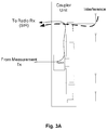
- Figs. 3A and 3B show interferences in the AC scenarios of Figs. 1A and 1B , respectively.
- the interference from ARP enters the radio receiver via the coupler.
- the interference from ARP enters the measurement receiver via the coupler and the switch.
- the AC accuracy is largely dependent on the Signal to Interference and Noise Ratio (SINR) at the radio receiver ( Fig. 3A ) or the measurement receiver ( Fig. 3B ).
- SINR Signal to Interference and Noise Ratio
- SINR Signal to Noise Ratio
- SIR Signal to Interference Ratio
- the SIR can be improved by increasing the power level of the calibration signal transmitted by the measurement transmitter.
- the measurement transmitter (which operates at the same frequency as the radio receiver) generates spurious emission at the ARP, which should be limited to a specified power spectral density (e.g., lower than -85dBm/MHz for Time Division Duplex (TDD) or -110dBm/100KHz for Frequency Division Duplex (FDD)).
- TDD Time Division Duplex
- FDD Frequency Division Duplex
- the measurement receiver suffers from strong in-channel or adjacent-channel interference, especially when there are other transceivers co-located.
- the SIR will be even worse if the transceiver is used in a low power station, e.g., a micro/pico base station or user equipment (UE).
- Fig. 4 shows a possible interference scenario where the transceiver is used in a base station. If the serial AC sequence is adopted, traffics in other radio branches could result in interferences through mutual antenna leakage (i.e., self-interference). That is, the AC has to suffer from cumulative interferences from all of other radio branches. In addition, there will be inter-station interferences from other base stations, which could be at maximum 25dBm (considering a 50dBm interference and a 25dB antenna isolation). There is thus a need for an AC solution with improved SIR and thus improved accuracy.
- antenna calibration examples are disclosed in some articles and patent applications, e.g. an article " OFDM-MIMO WLAN AP front-end gain and phase mismatch calibration” by Jian Liu et al., published at Radio and Wireless conference, 2004, pages 151-154 .
- US 2006/0044185 discloses an antenna calibration system is disclosed for calibrating an antenna array having a plurality of antennas.
- US 2008/198773 discloses a method for transmitter leak-over cancellation.
- One aspect of the present application provides a method of facilitating antenna calibration, comprising:
- a second aspect of the present invention provides a method of facilitating antenna calibration comprising:
- the coupler 123 of Fig. 1 can be a directional coupler.
- the directional coupler includes four ports.
- Port #1 is an input port
- Port #2 is a transmitted port
- Port #3 is a coupled port
- Port #4 is an isolated port.
- any of Port #2, Port #3 and Port #4 can serve as the input port.
- Port #2 is the input port for example
- Port #1 is the transmitted port
- Port #3 is the isolated port
- Port #4 is the coupled port.
- the transmitted port has no phase shift (0°)
- the coupled port has a phase shift of 90°
- the isolated port has a phase shift of 180°.
- Fig. 6 is a schematic diagram showing an apparatus 600 for facilitating AC according to an embodiment of the present disclosure.
- the apparatus 600 includes a directional coupler 610 having a first port 611, a second port 612, a third port 613 and a fourth port 614.
- the first port 611 selectively connected to a radio transmitter or a radio receiver, e.g., via a switch (not shown).
- the second port 612 is connected to an antenna.
- the apparatus 600 further includes a power combiner/divider 620 having a first port 621, a second port 622 and a third port 623.
- the first port 621 of the power combiner/divider 620 is selectively connected to a measurement receiver or a measurement transmitter, e.g., via a switch (not shown).
- the second port 622 of the power combiner/divider 620 is connected to the third port 613 of the direction coupler 610.
- the first port 621 is its input port and the second port 622 and the third port 623 are its output ports; whereas when the power combiner/divider 620 serves as a power combiner, the second port 622 and the third port 623 are its input ports and the first port 621 is its output port.
- the apparatus 600 further includes a magnitude and phase adjustor 630 connected between the fourth port 614 of the directional coupler 610 and the third port 623 of the power combiner/divider 620.
- the magnitude and phase adjustor 620 is configured to be tuned such that any signal input to the second port 612 of the directional coupler 610 results in an output smaller than a predetermined threshold at the first port 621 of the power combiner/divider 620.
- the predetermined threshold can be set to a small value sufficiently close to zero. That is, any signal input to the second port 612 of the directional coupler 610 results in a substantially zero output at the first port 621 of the power combiner/divider 620.
- the magnitude and phase adjustor 620 is tuned such that any signal input to the first port 621 of the power combiner/divider 620 results in an output smaller than the predetermined threshold at the second port 612 of the directional coupler 610.
- the magnitude and phase adjustor 620 is a vector modulator (VM).
- Fig. 7 shows a structure of a VM.
- the VM can continuously adjust a magnitude of an input signal, RFin within a certain range.
- the VM can also continuously adjust a phase of the input signal RFin in a range from 0° to 360°.
- the VM first splits the input signal RFin, with a 90° network, into an in-phase (I) component and a quadrature (Q) component.
- the magnitudes and phases of the I and Q components are then adjusted independently by multiplying them with Direct Circuit (DC) vectors Vi and Vq, respectively.
- DC Direct Circuit
- Fig. 8 shows an example explaining how the magnitude and phase adjustor 620 can be tuned.
- the magnitude and phase adjustor 620 is the VM shown in Fig. 7 and is applied in an RF transceiver including more than one branch each including a radio transmitter, a radio receiver, an antenna and the apparatus 600.
- the radio transmitter in Branch #1 can transmit a signal which will enter Branch #2 via mutual leakage between these branches.
- the output of the power combiner is connected, via a switch, to the measurement receiver.
- the VM in Branch #2 is tuned until the signal received at the measurement receiver is substantially zero. It can be appreciated by those skilled in the art that it is exemplary only to use the mutual leakage between the branches as the signal source for tuning the VM and any other signal source can be used as appropriate.
- the apparatus 600 may further include a delayer 640 ( Fig. 6 ) connected between the third port 613 of the directional coupler 610 and the second port 622 of the power combiner/divider 620.
- the use of the delayer 640 introduces phase shift and thus can make the tuning of the magnitude and phase adjustor 620 easier.
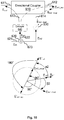
- Fig. 9 is a schematic diagram showing how the apparatus 600 of Fig. 6 works to facilitate AC associated with a radio transmitter.
- the directional coupler 610 is configured to connect its first port 611 to the radio transmitter such that a calibration signal, E in , from the radio transmitter is inputted to the first port 611 of the directional coupler 610 and results in a coupled calibration signal, E coup , at the third port 613 of the directional coupler 610 via coupling.
- the directional coupler 610 is configured to receive an interference signal, E int , from the antenna via its second port 612, such that the interference signal E int results in an isolated interference signal, E int_iso , at the third port 613 of the directional coupler 610 via isolation and a coupled interference signal, E int_coup, at the fourth port 614 of the directional coupler 610 via coupling.
- the magnitude and phase adjustor 630 is configured to modify a magnitude and a phase of the coupled interference signal E int_coup to generate a modified interference signal, E int_mod .
- the power combiner/divider 620 is configured to connect its first port 621 to the measurement receiver and combine the coupled calibration signal E coup , the isolated interference signal E int_iso and the modified interference signal E int_mod into an input, E out , to the measurement receiver.
- the delayer 640 can be provided and configured to delay, i.e., introduce a phase shift to, the coupled interference signal E int_coup and the isolated interference signal E int_iso , resulting in phase shifted signals E' int_coup and E' int_iso, respectively.
- Fig. 9 shows the magnitude and phase adjustment by the magnitude and phase adjustor 630.
- the delayer 640 is provided and introduces a phase shift of a1 to the isolated interference signal E int_iso , resulting in a phase shifted signals E' int_iso .
- the modified interference signal E int_mod has the same magnitude as E' int_iso but a 180° phase shift relative thereto.
- the interference from the ARP i.e., E int , does not contribute to the interference at the measurement receiver. Accordingly, the SIR at the measurement receiver can be improved.
- Fig. 10 is a schematic diagram showing how the apparatus 600 of Fig. 6 works to facilitate AC associated with a radio receiver.
- the power combiner/divider 620 is configured to connect its first port 621 to the measurement transmitter such that a calibration signal, E in , from the measurement transmitter is inputted to the first port 621 of the power combiner/divider 620.
- the power combiner/divider 620 is configured to divide the calibration signal E in into a first component signal E in1 and a second component signal E in2 outputted from the second 622 and third 623 ports of the power combiner/divider 620, respectively.
- the first component signal E in1 and the second component signal E in2 have the same phase and their magnitudes can be the same or different.
- the first component signal E in1 results in an isolated signal, E in1_iso , at the second port 612 of the directional coupler 610 via isolation.
- the first component signal E in1 also results in a signal, E out , at the first port 611 of the directional coupler 610, which is to be inputted to the radio receiver.
- the magnitude and phase adjustor 630 is configured to modify a magnitude and a phase of the second component signal E in2 to generate a modified signal, E in2_mod , which results in a coupled signal, E in2_coup , at the second port 612 of the directional coupler 610 via coupling.
- the delayer 640 can be provided and configured to delay, i.e., introduce a phase shift to, the first component signal E in1 , resulting in a phase shifted signal E' in1 .
- the phase shifted signal E' in1 results in an isolated signal, E' in1_iso , at the second port 612 of the directional coupler 610 via isolation.
- Fig. 10 shows the magnitude and phase adjustment by the magnitude and phase adjustor 630.
- the delayer 640 is provided and introduces a phase shift of a2 to the first component signal E in1 , resulting in a phase shifted signal E' in1 .
- There is inherently a phase shift of 90° between E in2_mod and E in2_coup the coupled signal E in2_coup and the isolated signal E' in1_iso cancel each other.
- the coupled signal E in2_coup has the same magnitude as the isolated signal E' in1_iso but a 180° phase shift relative thereto.
- the calibration signal E in does not contribute to the spurious emission at the ARP. Accordingly, the SIR at the radio receiver can be improved by increasing the power level of the calibration signal E in while satisfying the requirement on the spurious emission.
- the apparatus 600 works as long as the magnitude and phase adjustor 620 is tuned such that any signal input to the second port 612 of the directional coupler 610 results in a substantially zero output at the first port 621 of the power combiner/divider 620 (or equivalently, any signal input to the first port 621 of the power combiner/divider 620 results in a substantially zero output at the second port 612 of the directional coupler 610).
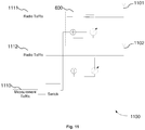
- Fig. 11 shows a transceiver 1100 according to an embodiment of the present disclosure.
- the transceiver 1100 can be a base station or user equipment.
- the transceiver 1100 includes: one or more branches each including a radio transmitter 1111, 1112, a radio receiver 1111, 1112 and an antenna 1101, 1102.
- the transceiver 1100 further includes a measurement transmitter and a measurement receiver 1110.
- Each branch further comprises an apparatus 600 of Fig. 6 .
- Fig. 11 shows a transceiver 1100 including two branches, it can be appreciated by those skilled in the art that the transceiver may include more or less branches and the present disclosure is not limited to any specific number of branches included in the transceiver.
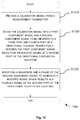
- Fig. 12 is a flowchart showing a method 1200 for facilitating AC associated with a radio transmitter according to an embodiment of the present disclosure.
- the method 1200 can be implemented using the apparatus 600 of Fig. 6 and includes the following steps.
- a calibration signal from a radio transmitter is received at a first port of a directional coupler, such that the calibration signal results in a coupled calibration signal at a third port of the directional coupler via coupling.
- an interference signal from an antenna is received at a second port the directional coupler, such that the interference signal results in an isolated interference signal at the third port of the directional coupler via isolation and a coupled interference signal at a fourth port of the directional coupler via coupling.
- a magnitude and a phase of the coupled interference signal are modified to generate a modified interference signal.
- the coupled calibration signal, the isolated interference signal and the modified interference signal are combined into an input to a measurement receiver.
- the modified interference signal and the isolated interference signal cancel each other.
- the modified interference signal has the same magnitude as the isolated interference signal but a 180° phase shift relative thereto.
- the method 1200 further includes, prior to the step S1240, a step of delaying the isolated interference signal.
- Fig. 13 is a flowchart showing a method 1300 for facilitating AC associated with a radio receiver according to an embodiment of the present disclosure.
- the method 1300 can be implemented using the apparatus 600 of Fig. 6 and includes the following steps.
- a calibration signal from a measurement transmitter is received.
- the calibration signal is divided into a first component signal and a second component signal to be inputted to a third port and fourth port of a directional coupler, respectively.
- the first component signal results in an isolated signal at a second port of the directional coupler via isolation.
- a magnitude and a phase of the second component signal are modified to generate a modified signal which results in a coupled signal at the second port of the directional coupler via coupling.
- the coupled signal and the isolated signal cancel each other.
- the coupled signal has the same magnitude as the isolated signal but a 180° phase shift relative thereto.
- the method 1300 further includes a step of delaying the first component signal before it is inputted to the third port of the directional coupler.
Landscapes
- Physics & Mathematics (AREA)
- Electromagnetism (AREA)
- Engineering & Computer Science (AREA)
- Computer Networks & Wireless Communication (AREA)
- Signal Processing (AREA)
- Transmitters (AREA)
- Variable-Direction Aerials And Aerial Arrays (AREA)
- Mobile Radio Communication Systems (AREA)
- Transceivers (AREA)
Claims (6)
- Verfahren zum Ermöglichen einer Antennenkalibrierung, das Folgendes umfasst:
Bereitstellen einer Vorrichtung, die Folgendes umfasst:einen Richtkoppler mit einem ersten Anschluss (611), einem zweiten Anschluss (612), einem dritten Anschluss (613) und einem vierten Anschluss (614), einen Leistungskombinierer/-teiler (62) mit einem ersten Anschluss (621), einem zweiten Anschluss (622) und einem dritten Anschluss (623) und einen Größen- und Phaseneinsteller (63), der zwischen dem vierten Anschluss des Richtkopplers und dem dritten Anschluss des Leistungskombinierers/-teilers verbunden ist; undAuslegen der Vorrichtung zu Folgendem:Empfangen (S1210) eines Kalibriersignals von einem Funksender am ersten Anschluss des Richtkopplers, derart, dass das Kalibriersignal am dritten Anschluss des Richtkopplers via Kopplung in einem gekoppelten Kalibriersignal resultiert;Empfangen (S1220) eines Interferenzsignals am zweiten Anschluss des Richtkopplers von einer Antenne, derart, dass das Interferenzsignal am dritten Anschluss des Richtkopplers via Isolierung in einem isolierten Interferenzsignal und am vierten Anschluss des Richtkopplers via Kopplung in einem gekoppelten Interferenzsignal resultiert;Ändern (S1230) einer Größe und einer Phase des gekoppelten Interferenzsignals, um ein geändertes Interferenzsignal zu erzeugen; undKombinieren (S1240) des gekoppelten Kalibriersignals, des isolierten Interferenzsignals und des geänderten Interferenzsignals zu einer Eingabe in einen Messungsempfänger, wobei das geänderte Interferenzsignal und das isolierte Interferenzsignal einander aufheben. - Verfahren nach Anspruch 1, wobei das geänderte Interferenzsignal dieselbe Größe wie das isolierte Interferenzsignal, aber eine Phasenverschiebung von 180° dazu aufweist.
- Verfahren nach Anspruch 1 oder 2, wobei die Vorrichtung dazu ausgelegt ist, vor dem Kombinieren das isolierte Interferenzsignal zu verzögern.
- Verfahren zum Ermöglichen einer Antennenkalibrierung, das Folgendes umfasst:Bereitstellen einer Vorrichtung, die einen Richtkoppler mit einem ersten Anschluss (611), einem zweiten Anschluss (612), einem dritten Anschluss (613) und einem vierten Anschluss (614), einen Leistungskombinierer/-teiler (62) mit einem ersten Anschluss (621), einem zweiten Anschluss (622) und einem dritten Anschluss (623) und einen Größen- und Phaseneinsteller (63), der zwischen dem vierten Anschluss des Richtkopplers und dem dritten Anschluss des Leistungskombinierers/-teilers verbunden ist, umfasst; undAuslegen der Vorrichtung zu Folgendem:Empfangen (S1310) eines Kalibriersignals von einem Messungssender;Teilen (S1320) des Kalibriersignals in ein erstes Komponentensignal und ein zweites Komponentensignal, die in den dritten Anschluss bzw. den vierten Anschluss des Richtkopplers einzugeben sind, wobei das erste Komponentensignal am zweiten Anschluss des Richtkopplers via Isolierung in einem isolierten Signal resultiert; undÄndern (S1330) einer Größe und einer Phase des zweiten Komponentensignals, um ein geändertes Signal zu erzeugen, das am zweiten Anschluss des Richtkopplers via Kopplung in einem gekoppelten Signal resultiert, wobei das gekoppelte Signal und das isolierte Signal einander aufheben.
- Verfahren nach Anspruch 4, wobei das gekoppelte Signal dieselbe Größe wie das isolierte Signal, aber eine Phasenverschiebung von 180° dazu aufweist.
- Verfahren nach Anspruch 4 oder 5, wobei die Vorrichtung dazu ausgelegt ist, das erste Komponentensignal zu verzögern, bevor es in den dritten Anschluss des Richtkopplers eingegeben wird.
Priority Applications (1)
| Application Number | Priority Date | Filing Date | Title |
|---|---|---|---|
| EP19191144.5A EP3584962B1 (de) | 2014-09-11 | 2014-09-11 | Verfahren und vorrichtung zur antennenkalibrierung und sender-empfänger |
Applications Claiming Priority (3)
| Application Number | Priority Date | Filing Date | Title |
|---|---|---|---|
| EP14901740.2A EP3192194B1 (de) | 2014-09-11 | 2014-09-11 | Verfahren und vorrichtung zur antennenkalibrierung und sender-empfänger |
| EP19191144.5A EP3584962B1 (de) | 2014-09-11 | 2014-09-11 | Verfahren und vorrichtung zur antennenkalibrierung und sender-empfänger |
| PCT/CN2014/086294 WO2016037338A1 (en) | 2014-09-11 | 2014-09-11 | Method and apparatus for facilitating antenna calibration and transceiver |
Related Parent Applications (1)
| Application Number | Title | Priority Date | Filing Date |
|---|---|---|---|
| EP14901740.2A Division EP3192194B1 (de) | 2014-09-11 | 2014-09-11 | Verfahren und vorrichtung zur antennenkalibrierung und sender-empfänger |
Publications (2)
| Publication Number | Publication Date |
|---|---|
| EP3584962A1 EP3584962A1 (de) | 2019-12-25 |
| EP3584962B1 true EP3584962B1 (de) | 2020-12-02 |
Family
ID=55458262
Family Applications (2)
| Application Number | Title | Priority Date | Filing Date |
|---|---|---|---|
| EP19191144.5A Not-in-force EP3584962B1 (de) | 2014-09-11 | 2014-09-11 | Verfahren und vorrichtung zur antennenkalibrierung und sender-empfänger |
| EP14901740.2A Not-in-force EP3192194B1 (de) | 2014-09-11 | 2014-09-11 | Verfahren und vorrichtung zur antennenkalibrierung und sender-empfänger |
Family Applications After (1)
| Application Number | Title | Priority Date | Filing Date |
|---|---|---|---|
| EP14901740.2A Not-in-force EP3192194B1 (de) | 2014-09-11 | 2014-09-11 | Verfahren und vorrichtung zur antennenkalibrierung und sender-empfänger |
Country Status (9)
| Country | Link |
|---|---|
| US (1) | US10014963B2 (de) |
| EP (2) | EP3584962B1 (de) |
| CN (1) | CN106664143B (de) |
| DK (1) | DK3192194T3 (de) |
| ES (1) | ES2748170T3 (de) |
| HU (1) | HUE046563T2 (de) |
| PL (1) | PL3192194T3 (de) |
| PT (1) | PT3192194T (de) |
| WO (1) | WO2016037338A1 (de) |
Families Citing this family (7)
| Publication number | Priority date | Publication date | Assignee | Title |
|---|---|---|---|---|
| WO2018112879A1 (en) * | 2016-12-23 | 2018-06-28 | Telefonaktiebolaget Lm Ericsson (Publ) | Antenna calibration for multiple input multiple output |
| CN108768549B (zh) * | 2018-08-10 | 2023-09-19 | 昆山恩电开通信设备有限公司 | 一种应用于5g通信的多天线校准网络装置 |
| WO2021102480A2 (en) * | 2020-03-10 | 2021-05-27 | Zeku, Inc. | Delay-line based transceiver calibration |
| CN112702127B (zh) * | 2020-12-07 | 2022-10-25 | 北京无线电计量测试研究所 | 一种t型网络测量方法和系统 |
| WO2022187601A1 (en) * | 2021-03-05 | 2022-09-09 | Qorvo Us, Inc. | Isolation provision from multiple antennas to a single antenna |
| CN113156199B (zh) * | 2021-04-20 | 2024-02-06 | 中国科学院近代物理研究所 | 一种射频功率测量装置及方法 |
| GB2642530A (en) * | 2024-07-12 | 2026-01-14 | Nokia Technologies Oy | A user equipment and network node |
Family Cites Families (7)
| Publication number | Priority date | Publication date | Assignee | Title |
|---|---|---|---|---|
| US5936569A (en) | 1997-12-02 | 1999-08-10 | Nokia Telecommunications Oy | Method and arrangement for adjusting antenna pattern |
| US7209078B2 (en) * | 2004-08-31 | 2007-04-24 | Navini Networks, Inc. | Antenna array calibration |
| EP1791278A1 (de) * | 2005-11-29 | 2007-05-30 | Interuniversitair Microelektronica Centrum (IMEC) | Verfahren und Vorrichtung zum Eichen von MIMO-Systemen |
| US7756480B2 (en) | 2007-02-16 | 2010-07-13 | Samsung Electronics Co., Ltd. | System and method for transmitter leak-over cancellation |
| US8102785B2 (en) * | 2008-05-21 | 2012-01-24 | Alcatel Lucent | Calibrating radiofrequency paths of a phased-array antenna |
| CN101826903B (zh) * | 2010-04-26 | 2013-05-01 | 京信通信系统(中国)有限公司 | 多通道通信系统的幅相特性校准方法及其装置 |
| US20130260844A1 (en) * | 2012-03-28 | 2013-10-03 | Andrew Llc | Series-connected couplers for active antenna systems |
-
2014
- 2014-09-11 US US15/500,860 patent/US10014963B2/en active Active
- 2014-09-11 DK DK14901740.2T patent/DK3192194T3/da active
- 2014-09-11 EP EP19191144.5A patent/EP3584962B1/de not_active Not-in-force
- 2014-09-11 PT PT149017402T patent/PT3192194T/pt unknown
- 2014-09-11 CN CN201480081690.6A patent/CN106664143B/zh active Active
- 2014-09-11 HU HUE14901740A patent/HUE046563T2/hu unknown
- 2014-09-11 PL PL14901740T patent/PL3192194T3/pl unknown
- 2014-09-11 ES ES14901740T patent/ES2748170T3/es active Active
- 2014-09-11 WO PCT/CN2014/086294 patent/WO2016037338A1/en not_active Ceased
- 2014-09-11 EP EP14901740.2A patent/EP3192194B1/de not_active Not-in-force
Non-Patent Citations (1)
| Title |
|---|
| None * |
Also Published As
| Publication number | Publication date |
|---|---|
| EP3192194A1 (de) | 2017-07-19 |
| EP3192194B1 (de) | 2019-08-28 |
| DK3192194T3 (da) | 2019-10-07 |
| EP3192194A4 (de) | 2018-04-18 |
| CN106664143B (zh) | 2020-10-27 |
| US10014963B2 (en) | 2018-07-03 |
| US20170222739A1 (en) | 2017-08-03 |
| WO2016037338A1 (en) | 2016-03-17 |
| EP3584962A1 (de) | 2019-12-25 |
| ES2748170T3 (es) | 2020-03-13 |
| PT3192194T (pt) | 2019-10-15 |
| HUE046563T2 (hu) | 2020-03-30 |
| PL3192194T3 (pl) | 2019-12-31 |
| CN106664143A (zh) | 2017-05-10 |
Similar Documents
| Publication | Publication Date | Title |
|---|---|---|
| EP3584962B1 (de) | Verfahren und vorrichtung zur antennenkalibrierung und sender-empfänger | |
| CN106797221B (zh) | 用于在多载波发射器中使用的互调失真消除器 | |
| EP3579339B1 (de) | Kalibrierung eines gruppenantennensystems | |
| US8731005B2 (en) | Absolute timing and Tx power calibration of the Tx path in a distributed system | |
| US9392558B2 (en) | Control of transmit power and adjustment of antenna tuning network of a wireless device | |
| US9621330B2 (en) | Split microwave backhaul transceiver architecture with coaxial interconnect | |
| TWI565233B (zh) | 用以放大傳輸信號或用以判定延遲控制參數之值的設備及方法 | |
| CN105684320B (zh) | 带有内部并行天线校准的无线电单元 | |
| CN102237906A (zh) | 使用信号对消改善天线隔离的系统和方法 | |
| US10142006B1 (en) | Amplitude and phase calibration at a receiver chip in an antenna array | |
| US10447372B2 (en) | Amplitude and phase calibration at a transmitter chip in an antenna array | |
| US11456807B2 (en) | Apparatus and method for correcting deviation between plurality of transmission channels | |
| Aoki et al. | Fast characterization of phased-array elements using orthogonal codes | |
| Roussel et al. | Frequency agile RF feedforward noise cancellation system | |
| HK40018304A (en) | Method and apparatus for facilitating antenna calibration and transceiver | |
| HK40018304B (en) | Method and apparatus for facilitating antenna calibration and transceiver | |
| Balteanu | RF circuit techniques for transition to 5G advanced | |
| Balteanu et al. | Enabling RF Circuit Techniques for 5G and beyond | |
| KR102076745B1 (ko) | 벡터 모듈레이터를 이용한 간섭 제거 장치, 시스템 및 방법 | |
| KR20210151601A (ko) | 비대칭 스위치를 이용한 밀리미터파 송수신단 | |
| KR101601068B1 (ko) | 위상 배열 안테나를 이용하여 광대역 신호를 송수신하기 위한 방법, 시스템 및 컴퓨터 판독 가능한 기록 매체 |
Legal Events
| Date | Code | Title | Description |
|---|---|---|---|
| PUAI | Public reference made under article 153(3) epc to a published international application that has entered the european phase |
Free format text: ORIGINAL CODE: 0009012 |
|
| STAA | Information on the status of an ep patent application or granted ep patent |
Free format text: STATUS: THE APPLICATION HAS BEEN PUBLISHED |
|
| AC | Divisional application: reference to earlier application |
Ref document number: 3192194 Country of ref document: EP Kind code of ref document: P |
|
| AK | Designated contracting states |
Kind code of ref document: A1 Designated state(s): AL AT BE BG CH CY CZ DE DK EE ES FI FR GB GR HR HU IE IS IT LI LT LU LV MC MK MT NL NO PL PT RO RS SE SI SK SM TR |
|
| STAA | Information on the status of an ep patent application or granted ep patent |
Free format text: STATUS: REQUEST FOR EXAMINATION WAS MADE |
|
| 17P | Request for examination filed |
Effective date: 20200526 |
|
| RBV | Designated contracting states (corrected) |
Designated state(s): AL AT BE BG CH CY CZ DE DK EE ES FI FR GB GR HR HU IE IS IT LI LT LU LV MC MK MT NL NO PL PT RO RS SE SI SK SM TR |
|
| GRAP | Despatch of communication of intention to grant a patent |
Free format text: ORIGINAL CODE: EPIDOSNIGR1 |
|
| STAA | Information on the status of an ep patent application or granted ep patent |
Free format text: STATUS: GRANT OF PATENT IS INTENDED |
|
| INTG | Intention to grant announced |
Effective date: 20200707 |
|
| REG | Reference to a national code |
Ref country code: HK Ref legal event code: DE Ref document number: 40018304 Country of ref document: HK |
|
| GRAS | Grant fee paid |
Free format text: ORIGINAL CODE: EPIDOSNIGR3 |
|
| GRAA | (expected) grant |
Free format text: ORIGINAL CODE: 0009210 |
|
| STAA | Information on the status of an ep patent application or granted ep patent |
Free format text: STATUS: THE PATENT HAS BEEN GRANTED |
|
| AC | Divisional application: reference to earlier application |
Ref document number: 3192194 Country of ref document: EP Kind code of ref document: P |
|
| AK | Designated contracting states |
Kind code of ref document: B1 Designated state(s): AL AT BE BG CH CY CZ DE DK EE ES FI FR GB GR HR HU IE IS IT LI LT LU LV MC MK MT NL NO PL PT RO RS SE SI SK SM TR |
|
| REG | Reference to a national code |
Ref country code: GB Ref legal event code: FG4D |
|
| REG | Reference to a national code |
Ref country code: AT Ref legal event code: REF Ref document number: 1342068 Country of ref document: AT Kind code of ref document: T Effective date: 20201215 Ref country code: CH Ref legal event code: EP |
|
| REG | Reference to a national code |
Ref country code: IE Ref legal event code: FG4D |
|
| REG | Reference to a national code |
Ref country code: DE Ref legal event code: R096 Ref document number: 602014073120 Country of ref document: DE |
|
| PG25 | Lapsed in a contracting state [announced via postgrant information from national office to epo] |
Ref country code: GR Free format text: LAPSE BECAUSE OF FAILURE TO SUBMIT A TRANSLATION OF THE DESCRIPTION OR TO PAY THE FEE WITHIN THE PRESCRIBED TIME-LIMIT Effective date: 20210303 Ref country code: NO Free format text: LAPSE BECAUSE OF FAILURE TO SUBMIT A TRANSLATION OF THE DESCRIPTION OR TO PAY THE FEE WITHIN THE PRESCRIBED TIME-LIMIT Effective date: 20210302 Ref country code: FI Free format text: LAPSE BECAUSE OF FAILURE TO SUBMIT A TRANSLATION OF THE DESCRIPTION OR TO PAY THE FEE WITHIN THE PRESCRIBED TIME-LIMIT Effective date: 20201202 Ref country code: RS Free format text: LAPSE BECAUSE OF FAILURE TO SUBMIT A TRANSLATION OF THE DESCRIPTION OR TO PAY THE FEE WITHIN THE PRESCRIBED TIME-LIMIT Effective date: 20201202 |
|
| REG | Reference to a national code |
Ref country code: NL Ref legal event code: MP Effective date: 20201202 |
|
| REG | Reference to a national code |
Ref country code: AT Ref legal event code: MK05 Ref document number: 1342068 Country of ref document: AT Kind code of ref document: T Effective date: 20201202 |
|
| PG25 | Lapsed in a contracting state [announced via postgrant information from national office to epo] |
Ref country code: BG Free format text: LAPSE BECAUSE OF FAILURE TO SUBMIT A TRANSLATION OF THE DESCRIPTION OR TO PAY THE FEE WITHIN THE PRESCRIBED TIME-LIMIT Effective date: 20210302 Ref country code: SE Free format text: LAPSE BECAUSE OF FAILURE TO SUBMIT A TRANSLATION OF THE DESCRIPTION OR TO PAY THE FEE WITHIN THE PRESCRIBED TIME-LIMIT Effective date: 20201202 Ref country code: LV Free format text: LAPSE BECAUSE OF FAILURE TO SUBMIT A TRANSLATION OF THE DESCRIPTION OR TO PAY THE FEE WITHIN THE PRESCRIBED TIME-LIMIT Effective date: 20201202 Ref country code: PL Free format text: LAPSE BECAUSE OF FAILURE TO SUBMIT A TRANSLATION OF THE DESCRIPTION OR TO PAY THE FEE WITHIN THE PRESCRIBED TIME-LIMIT Effective date: 20201202 |
|
| PG25 | Lapsed in a contracting state [announced via postgrant information from national office to epo] |
Ref country code: NL Free format text: LAPSE BECAUSE OF FAILURE TO SUBMIT A TRANSLATION OF THE DESCRIPTION OR TO PAY THE FEE WITHIN THE PRESCRIBED TIME-LIMIT Effective date: 20201202 Ref country code: HR Free format text: LAPSE BECAUSE OF FAILURE TO SUBMIT A TRANSLATION OF THE DESCRIPTION OR TO PAY THE FEE WITHIN THE PRESCRIBED TIME-LIMIT Effective date: 20201202 |
|
| REG | Reference to a national code |
Ref country code: LT Ref legal event code: MG9D |
|
| PG25 | Lapsed in a contracting state [announced via postgrant information from national office to epo] |
Ref country code: EE Free format text: LAPSE BECAUSE OF FAILURE TO SUBMIT A TRANSLATION OF THE DESCRIPTION OR TO PAY THE FEE WITHIN THE PRESCRIBED TIME-LIMIT Effective date: 20201202 Ref country code: SM Free format text: LAPSE BECAUSE OF FAILURE TO SUBMIT A TRANSLATION OF THE DESCRIPTION OR TO PAY THE FEE WITHIN THE PRESCRIBED TIME-LIMIT Effective date: 20201202 Ref country code: SK Free format text: LAPSE BECAUSE OF FAILURE TO SUBMIT A TRANSLATION OF THE DESCRIPTION OR TO PAY THE FEE WITHIN THE PRESCRIBED TIME-LIMIT Effective date: 20201202 Ref country code: CZ Free format text: LAPSE BECAUSE OF FAILURE TO SUBMIT A TRANSLATION OF THE DESCRIPTION OR TO PAY THE FEE WITHIN THE PRESCRIBED TIME-LIMIT Effective date: 20201202 Ref country code: LT Free format text: LAPSE BECAUSE OF FAILURE TO SUBMIT A TRANSLATION OF THE DESCRIPTION OR TO PAY THE FEE WITHIN THE PRESCRIBED TIME-LIMIT Effective date: 20201202 Ref country code: PT Free format text: LAPSE BECAUSE OF FAILURE TO SUBMIT A TRANSLATION OF THE DESCRIPTION OR TO PAY THE FEE WITHIN THE PRESCRIBED TIME-LIMIT Effective date: 20210405 Ref country code: RO Free format text: LAPSE BECAUSE OF FAILURE TO SUBMIT A TRANSLATION OF THE DESCRIPTION OR TO PAY THE FEE WITHIN THE PRESCRIBED TIME-LIMIT Effective date: 20201202 |
|
| PG25 | Lapsed in a contracting state [announced via postgrant information from national office to epo] |
Ref country code: AT Free format text: LAPSE BECAUSE OF FAILURE TO SUBMIT A TRANSLATION OF THE DESCRIPTION OR TO PAY THE FEE WITHIN THE PRESCRIBED TIME-LIMIT Effective date: 20201202 |
|
| REG | Reference to a national code |
Ref country code: DE Ref legal event code: R097 Ref document number: 602014073120 Country of ref document: DE |
|
| PG25 | Lapsed in a contracting state [announced via postgrant information from national office to epo] |
Ref country code: IS Free format text: LAPSE BECAUSE OF FAILURE TO SUBMIT A TRANSLATION OF THE DESCRIPTION OR TO PAY THE FEE WITHIN THE PRESCRIBED TIME-LIMIT Effective date: 20210402 |
|
| PLBE | No opposition filed within time limit |
Free format text: ORIGINAL CODE: 0009261 |
|
| STAA | Information on the status of an ep patent application or granted ep patent |
Free format text: STATUS: NO OPPOSITION FILED WITHIN TIME LIMIT |
|
| PG25 | Lapsed in a contracting state [announced via postgrant information from national office to epo] |
Ref country code: IT Free format text: LAPSE BECAUSE OF FAILURE TO SUBMIT A TRANSLATION OF THE DESCRIPTION OR TO PAY THE FEE WITHIN THE PRESCRIBED TIME-LIMIT Effective date: 20201202 Ref country code: AL Free format text: LAPSE BECAUSE OF FAILURE TO SUBMIT A TRANSLATION OF THE DESCRIPTION OR TO PAY THE FEE WITHIN THE PRESCRIBED TIME-LIMIT Effective date: 20201202 |
|
| PGFP | Annual fee paid to national office [announced via postgrant information from national office to epo] |
Ref country code: FR Payment date: 20210929 Year of fee payment: 8 |
|
| 26N | No opposition filed |
Effective date: 20210903 |
|
| PG25 | Lapsed in a contracting state [announced via postgrant information from national office to epo] |
Ref country code: DK Free format text: LAPSE BECAUSE OF FAILURE TO SUBMIT A TRANSLATION OF THE DESCRIPTION OR TO PAY THE FEE WITHIN THE PRESCRIBED TIME-LIMIT Effective date: 20201202 Ref country code: SI Free format text: LAPSE BECAUSE OF FAILURE TO SUBMIT A TRANSLATION OF THE DESCRIPTION OR TO PAY THE FEE WITHIN THE PRESCRIBED TIME-LIMIT Effective date: 20201202 |
|
| PGFP | Annual fee paid to national office [announced via postgrant information from national office to epo] |
Ref country code: DE Payment date: 20210921 Year of fee payment: 8 Ref country code: GB Payment date: 20210923 Year of fee payment: 8 |
|
| PG25 | Lapsed in a contracting state [announced via postgrant information from national office to epo] |
Ref country code: ES Free format text: LAPSE BECAUSE OF FAILURE TO SUBMIT A TRANSLATION OF THE DESCRIPTION OR TO PAY THE FEE WITHIN THE PRESCRIBED TIME-LIMIT Effective date: 20201202 |
|
| REG | Reference to a national code |
Ref country code: CH Ref legal event code: PL |
|
| REG | Reference to a national code |
Ref country code: BE Ref legal event code: MM Effective date: 20210930 |
|
| PG25 | Lapsed in a contracting state [announced via postgrant information from national office to epo] |
Ref country code: IS Free format text: LAPSE BECAUSE OF FAILURE TO SUBMIT A TRANSLATION OF THE DESCRIPTION OR TO PAY THE FEE WITHIN THE PRESCRIBED TIME-LIMIT Effective date: 20210402 Ref country code: MC Free format text: LAPSE BECAUSE OF FAILURE TO SUBMIT A TRANSLATION OF THE DESCRIPTION OR TO PAY THE FEE WITHIN THE PRESCRIBED TIME-LIMIT Effective date: 20201202 |
|
| PG25 | Lapsed in a contracting state [announced via postgrant information from national office to epo] |
Ref country code: LU Free format text: LAPSE BECAUSE OF NON-PAYMENT OF DUE FEES Effective date: 20210911 Ref country code: IE Free format text: LAPSE BECAUSE OF NON-PAYMENT OF DUE FEES Effective date: 20210911 Ref country code: BE Free format text: LAPSE BECAUSE OF NON-PAYMENT OF DUE FEES Effective date: 20210930 |
|
| PG25 | Lapsed in a contracting state [announced via postgrant information from national office to epo] |
Ref country code: LI Free format text: LAPSE BECAUSE OF NON-PAYMENT OF DUE FEES Effective date: 20210930 Ref country code: CH Free format text: LAPSE BECAUSE OF NON-PAYMENT OF DUE FEES Effective date: 20210930 |
|
| REG | Reference to a national code |
Ref country code: DE Ref legal event code: R119 Ref document number: 602014073120 Country of ref document: DE |
|
| GBPC | Gb: european patent ceased through non-payment of renewal fee |
Effective date: 20220911 |
|
| P01 | Opt-out of the competence of the unified patent court (upc) registered |
Effective date: 20230412 |
|
| PG25 | Lapsed in a contracting state [announced via postgrant information from national office to epo] |
Ref country code: CY Free format text: LAPSE BECAUSE OF FAILURE TO SUBMIT A TRANSLATION OF THE DESCRIPTION OR TO PAY THE FEE WITHIN THE PRESCRIBED TIME-LIMIT Effective date: 20201202 |
|
| PG25 | Lapsed in a contracting state [announced via postgrant information from national office to epo] |
Ref country code: HU Free format text: LAPSE BECAUSE OF FAILURE TO SUBMIT A TRANSLATION OF THE DESCRIPTION OR TO PAY THE FEE WITHIN THE PRESCRIBED TIME-LIMIT; INVALID AB INITIO Effective date: 20140911 Ref country code: FR Free format text: LAPSE BECAUSE OF NON-PAYMENT OF DUE FEES Effective date: 20220930 Ref country code: DE Free format text: LAPSE BECAUSE OF NON-PAYMENT OF DUE FEES Effective date: 20230401 |
|
| PG25 | Lapsed in a contracting state [announced via postgrant information from national office to epo] |
Ref country code: GB Free format text: LAPSE BECAUSE OF NON-PAYMENT OF DUE FEES Effective date: 20220911 |
|
| PG25 | Lapsed in a contracting state [announced via postgrant information from national office to epo] |
Ref country code: MK Free format text: LAPSE BECAUSE OF FAILURE TO SUBMIT A TRANSLATION OF THE DESCRIPTION OR TO PAY THE FEE WITHIN THE PRESCRIBED TIME-LIMIT Effective date: 20201202 |
|
| PG25 | Lapsed in a contracting state [announced via postgrant information from national office to epo] |
Ref country code: MT Free format text: LAPSE BECAUSE OF FAILURE TO SUBMIT A TRANSLATION OF THE DESCRIPTION OR TO PAY THE FEE WITHIN THE PRESCRIBED TIME-LIMIT Effective date: 20201202 |
|
| PG25 | Lapsed in a contracting state [announced via postgrant information from national office to epo] |
Ref country code: TR Free format text: LAPSE BECAUSE OF FAILURE TO SUBMIT A TRANSLATION OF THE DESCRIPTION OR TO PAY THE FEE WITHIN THE PRESCRIBED TIME-LIMIT Effective date: 20201202 |