EP3584855A1 - Output electrode plate and battery module - Google Patents
Output electrode plate and battery module Download PDFInfo
- Publication number
- EP3584855A1 EP3584855A1 EP18191807.9A EP18191807A EP3584855A1 EP 3584855 A1 EP3584855 A1 EP 3584855A1 EP 18191807 A EP18191807 A EP 18191807A EP 3584855 A1 EP3584855 A1 EP 3584855A1
- Authority
- EP
- European Patent Office
- Prior art keywords
- metal plate
- region
- output electrode
- electrode plate
- connection line
- Prior art date
- Legal status (The legal status is an assumption and is not a legal conclusion. Google has not performed a legal analysis and makes no representation as to the accuracy of the status listed.)
- Granted
Links
Images


Classifications
-
- H—ELECTRICITY
- H01—ELECTRIC ELEMENTS
- H01M—PROCESSES OR MEANS, e.g. BATTERIES, FOR THE DIRECT CONVERSION OF CHEMICAL ENERGY INTO ELECTRICAL ENERGY
- H01M50/00—Constructional details or processes of manufacture of the non-active parts of electrochemical cells other than fuel cells, e.g. hybrid cells
- H01M50/50—Current conducting connections for cells or batteries
- H01M50/572—Means for preventing undesired use or discharge
- H01M50/574—Devices or arrangements for the interruption of current
- H01M50/581—Devices or arrangements for the interruption of current in response to temperature
-
- H—ELECTRICITY
- H01—ELECTRIC ELEMENTS
- H01M—PROCESSES OR MEANS, e.g. BATTERIES, FOR THE DIRECT CONVERSION OF CHEMICAL ENERGY INTO ELECTRICAL ENERGY
- H01M50/00—Constructional details or processes of manufacture of the non-active parts of electrochemical cells other than fuel cells, e.g. hybrid cells
- H01M50/20—Mountings; Secondary casings or frames; Racks, modules or packs; Suspension devices; Shock absorbers; Transport or carrying devices; Holders
- H01M50/204—Racks, modules or packs for multiple batteries or multiple cells
- H01M50/207—Racks, modules or packs for multiple batteries or multiple cells characterised by their shape
- H01M50/211—Racks, modules or packs for multiple batteries or multiple cells characterised by their shape adapted for pouch cells
-
- H—ELECTRICITY
- H01—ELECTRIC ELEMENTS
- H01M—PROCESSES OR MEANS, e.g. BATTERIES, FOR THE DIRECT CONVERSION OF CHEMICAL ENERGY INTO ELECTRICAL ENERGY
- H01M50/00—Constructional details or processes of manufacture of the non-active parts of electrochemical cells other than fuel cells, e.g. hybrid cells
- H01M50/20—Mountings; Secondary casings or frames; Racks, modules or packs; Suspension devices; Shock absorbers; Transport or carrying devices; Holders
- H01M50/296—Mountings; Secondary casings or frames; Racks, modules or packs; Suspension devices; Shock absorbers; Transport or carrying devices; Holders characterised by terminals of battery packs
-
- H—ELECTRICITY
- H01—ELECTRIC ELEMENTS
- H01M—PROCESSES OR MEANS, e.g. BATTERIES, FOR THE DIRECT CONVERSION OF CHEMICAL ENERGY INTO ELECTRICAL ENERGY
- H01M50/00—Constructional details or processes of manufacture of the non-active parts of electrochemical cells other than fuel cells, e.g. hybrid cells
- H01M50/50—Current conducting connections for cells or batteries
- H01M50/502—Interconnectors for connecting terminals of adjacent batteries; Interconnectors for connecting cells outside a battery casing
- H01M50/503—Interconnectors for connecting terminals of adjacent batteries; Interconnectors for connecting cells outside a battery casing characterised by the shape of the interconnectors
-
- H—ELECTRICITY
- H01—ELECTRIC ELEMENTS
- H01M—PROCESSES OR MEANS, e.g. BATTERIES, FOR THE DIRECT CONVERSION OF CHEMICAL ENERGY INTO ELECTRICAL ENERGY
- H01M50/00—Constructional details or processes of manufacture of the non-active parts of electrochemical cells other than fuel cells, e.g. hybrid cells
- H01M50/50—Current conducting connections for cells or batteries
- H01M50/502—Interconnectors for connecting terminals of adjacent batteries; Interconnectors for connecting cells outside a battery casing
- H01M50/521—Interconnectors for connecting terminals of adjacent batteries; Interconnectors for connecting cells outside a battery casing characterised by the material
- H01M50/522—Inorganic material
-
- H—ELECTRICITY
- H01—ELECTRIC ELEMENTS
- H01M—PROCESSES OR MEANS, e.g. BATTERIES, FOR THE DIRECT CONVERSION OF CHEMICAL ENERGY INTO ELECTRICAL ENERGY
- H01M50/00—Constructional details or processes of manufacture of the non-active parts of electrochemical cells other than fuel cells, e.g. hybrid cells
- H01M50/50—Current conducting connections for cells or batteries
- H01M50/572—Means for preventing undesired use or discharge
- H01M50/574—Devices or arrangements for the interruption of current
- H01M50/583—Devices or arrangements for the interruption of current in response to current, e.g. fuses
-
- H—ELECTRICITY
- H01—ELECTRIC ELEMENTS
- H01M—PROCESSES OR MEANS, e.g. BATTERIES, FOR THE DIRECT CONVERSION OF CHEMICAL ENERGY INTO ELECTRICAL ENERGY
- H01M2200/00—Safety devices for primary or secondary batteries
-
- H—ELECTRICITY
- H01—ELECTRIC ELEMENTS
- H01M—PROCESSES OR MEANS, e.g. BATTERIES, FOR THE DIRECT CONVERSION OF CHEMICAL ENERGY INTO ELECTRICAL ENERGY
- H01M2200/00—Safety devices for primary or secondary batteries
- H01M2200/10—Temperature sensitive devices
- H01M2200/103—Fuse
-
- H—ELECTRICITY
- H01—ELECTRIC ELEMENTS
- H01M—PROCESSES OR MEANS, e.g. BATTERIES, FOR THE DIRECT CONVERSION OF CHEMICAL ENERGY INTO ELECTRICAL ENERGY
- H01M2220/00—Batteries for particular applications
- H01M2220/20—Batteries in motive systems, e.g. vehicle, ship, plane
-
- Y—GENERAL TAGGING OF NEW TECHNOLOGICAL DEVELOPMENTS; GENERAL TAGGING OF CROSS-SECTIONAL TECHNOLOGIES SPANNING OVER SEVERAL SECTIONS OF THE IPC; TECHNICAL SUBJECTS COVERED BY FORMER USPC CROSS-REFERENCE ART COLLECTIONS [XRACs] AND DIGESTS
- Y02—TECHNOLOGIES OR APPLICATIONS FOR MITIGATION OR ADAPTATION AGAINST CLIMATE CHANGE
- Y02E—REDUCTION OF GREENHOUSE GAS [GHG] EMISSIONS, RELATED TO ENERGY GENERATION, TRANSMISSION OR DISTRIBUTION
- Y02E60/00—Enabling technologies; Technologies with a potential or indirect contribution to GHG emissions mitigation
- Y02E60/10—Energy storage using batteries
Definitions
- the present disclosure relates to the technical field of the battery, and in particular, to an output electrode plate and a battery module.
- the power battery system is the assembly which is most directly relevant to the two parts of the electric vehicle. Therefore, the current core challenge is to solve the safety and low-cost problem of the power battery system.
- one aspect is to design a general safety fuse in the main circuit of the battery package system, acting as overload protection of the whole battery system circuit and the external short-circuit protection of the entire package.
- the other aspect is for square-case single cell and to provide a safety structure within the single cell level, to ensure the external short-circuit and overcharge safety of the single cell level.
- the above two aspects may solve the safety problem and low-cost problem of the power battery system to some extent, there are corresponding disadvantages.
- the main reason is that there is no corresponding safety structure at the module level that can ensure the external short-circuit safety protection at the module level.
- the external short-circuit manufacture at the module level may be caused due to human error, or when the whole vehicle is running, the external short-circuit manufacture at the module level may be caused when the wire harness between the internal module is broken or after the whole vehicle is crushed.
- the module-level external short-circuits in these two aspects are not covered by the general safety component that is designed in the main circuit of the battery package system.
- the safety structure cannot be designed at the single cell level within the pouch-type single cell like square-case single cell due to the structural space arrangement inside the cell, all the single cells within the module will have no fuse protection once the module formed by the pouch-type single cell is externally short-circuited, which may easily lead to serious safety problems such as thermal runaway or even explosion of the single cells within the module.
- Embodiments of the present disclosure provide an output electrode plate that can satisfy the output and input requirements of the power and can ensure the safety of the battery system at the module level.
- An embodiment of the present disclosure provides an output electrode plate for a battery module, the output electrode plate comprises a first metal plate; the first metal plate includes a first region and a second region that are successively distributed in a first direction; the first region includes a first overcurrent portion and a second overcurrent portion, the first overcurrent portion and the second overcurrent portion are successively distributed in a second direction and are connected with each other, wherein the second direction intersects with the first direction, and the second region is connected to the first region through the first overcurrent portion; wherein, the first overcurrent portion is provided with a through hole which extends in a thickness direction thereof, and a projection of the through hole along the first direction does not exceed a projection of the second region along the first direction in the second direction, and a minimum overcurrent section of the first metal plate is formed at the through hole, such that the minimum overcurrent section is first fused when a current flowing through the first metal plate is greater than a preset current.
- an intersection line where the minimum overcurrent section intersects with an upper surface of the first region in the thickness direction is a first connection line
- an orthographic projection on the upper surface of a connection surface where the first overcurrent portion connects to the second overcurrent portion is a second connection line, wherein the second connection line intersects with the first connection line
- an angle M is formed by the first connection line and the second connection line is, wherein 0° ⁇ M ⁇ 45°.
- the first region has a first edge and a second edge that are opposite in the first direction
- the second overcurrent portion is provided with a notch which is recessed from the first edge toward the second edge
- the second region is connected to the first edge and intersects with the first region, and at least part of a sidewall enclosing the notch flushes with an end surface of the second region in the second direction.
- the first connection line has a first end point a and a second end point b that are opposite, the first end point a is located on the sidewall of the notch, the second end point b is located on the second edge, and the first connection line passes through the through hole.
- the first region has a first edge and a second edge that are opposite in the first direction
- the first connection line has a first end point a and a second end point b that are opposite
- the first end point a is located on an end surface of the second region in the second direction and is an intersection point of the first connection line and the second connection line
- the second end point b is located on the second edge
- the first connection line passes through the through hole
- the first connection line has a length L, and the length is determined based on a characteristic parameter of the first metal plate, a time when the preset current flows through the first metal plate, and a preset diameter of the through hole.
- the characteristic parameter of the first metal plate is determined based on a constant coefficient of the first metal plate, the preset current flowing through the first metal plate, and a thickness of the first region of the first metal plate.
- the length of the first connection line is determined based on a relation: L ⁇ IK d t + ⁇
- I is the preset current flowing through the first metal plate
- K is the constant coefficient of the first metal plate
- d is the thickness of the first region of the first metal plate
- t is the time when the current flows through the first metal plate
- ⁇ is the preset diameter of the through hole.
- conductivity is the metal conductivity of the first metal plate
- C is the specific heat capacity of the first metal plate
- ⁇ density is the metal mass density of the first metal plate
- A is the metal melting point of the first metal plate.
- the through hole is provided away from the second region and is offset in the first direction from a center line of the first overcurrent portion in the first direction.
- the output electrode plate further comprises a second metal plate that is connected to the first metal plate, the second metal plate is provided with a connection port for electrical connection between the battery module.
- the output electrode plate comprises a first metal plate; the first metal plate includes a first region and a second region that are successively distributed in a first direction; the first region includes a first overcurrent portion and a second overcurrent portion, the first overcurrent portion and the second overcurrent portion are successively distributed in a second direction and are connected with each other, wherein the second direction intersects with the first direction, and the second region is connected to the first region through the first overcurrent portion; the first overcurrent portion is provided with a through hole which extends in a thickness direction thereof.
- the output electrode plate can be used for the battery module, and when used in the battery module, it may be electrically connected with the single cells in the battery module as a module output, so as to satisfy the input and output requirements of the power of the battery module. Due to the provision of the through hole in the first overcurrent portion, a minimum overcurrent section of the first metal plate is formed at the through hole, such that the minimum overcurrent section is first fused when the current flowing through the first metal plate is greater than the preset current, so as to ensure the safety of the battery module. Moreover, since the projection of the through hole along the first direction does not exceed the projection of the second region along the first direction in the second direction, the first metal plate may achieve the higher strength and is thus not prone to break while the protection requirement of the battery module is ensured.
- a battery module comprising a single cell pack, comprising a plurality of single cells that are electrically connected with each other; and the above mentioned output electrode plate, wherein the output electrode plate is electrically connected to the single cell of the single cell pack which is used as output module.
- the orientation words appearing in the following description refer to the directions shown in the drawings, and are not intended to limit the specific structure of the output electrode plate and the battery module of the present disclosure.
- the terms "mount”, “connect with”, and “connect to” are to be understood broadly, for example, it may be fixed connection or detachable connection or integral connection; it may be mechanical connection or electrical connection; it may be direct connection or indirect connection through an intermediate medium.
- the specific meaning of the above terms in the present disclosure may be understood by the skilled in the art based on the specific situation.
- Fig. 1 shows a perspective view of a battery module of an embodiment of the present disclosure
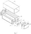
- Fig. 2 shows an exploded perspective view of the structure shown in Fig. 1 .
- an embodiment of the present disclosure provides a battery module 100, comprising a single cell pack 20 which includes a plurality of single cells that are electrically connected with each other, a spacer plate assembly 30 which is provided on the single cell pack 20, and an output electrode plate 10 which is electrically connected with the single cell in the plurality of single cell pack 20 that is used as module output, so as to satisfy the input and output requirements of the power of the battery module 100.
- the output electrode plate 10 may be provided on the spacer plate assembly 30 and be fixedly connected to the single cell pack 20 through the spacer plate assembly 30.
- the battery module 100 provided in the embodiment of the present disclosure may be a pouch-type battery module 100, and the single cell pack thereof 20 further includes a fixing frame 21, wherein the single cells are connected to the fixing frame 21 and form a cell unit together with the fixing frame 21.
- the formed cell units are stacked and connected with each other in series or in parallel, thereby achieving mutual electrical connection of the single cells.
- the battery module 100 is the pouch-type battery module 100, accordingly, each of the single cells has an electrode lead 22, and the output electrode plate 10 is specifically electrically connected to the electrode lead 22 of the single cell.
- the battery module 100 further includes a case 50 and an end plate 60 connected to the case 50.
- the battery module 100 provided in the embodiment of the present disclosure may employ different output electrode plate 10, as long as they can satisfy the input and output requirements of the power.
- the output electrode plate 10 that is integrated with the safety function is preferable, which may not only satisfy the input and output requirements of the power of the battery module 100, but also enable the battery module 100 to provide protection at its own module level. Therefore, it can protect the single battery pack thereof 20 in the event of an external short circuit.
- Fig. 3 shows a perspective view of an output electrode plate of one embodiment of the present disclosure
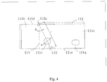
- Fig. 4 shows a plan view of the structure shown in Fig. 3
- the battery module 100 preferably utilizes the output electrode plate 10 shown in Figs. 3 and 4
- the output electrode plate 10 according to an embodiment of the present disclosure includes a first metal plate 11 including a first region 111 and a second region 112 that are successively distributed in a first direction X.
- the first region 111 includes a first overcurrent portion 111a and a second overcurrent portion 111b that are successively distributed in a second direction Y and are connected with each other, wherein the second direction Y intersects with the first direction X, and the second region 112 is connected to the first region 111 through the first overcurrent portion 111a.
- the first overcurrent portion 111a is provided with a through hole 111c which extends in the thickness direction Z thereof.
- the projection of the through hole 111c along the first direction X does not exceed the projection of the second region 112 along the first direction X in the second direction Y.
- a minimum overcurrent section of the first metal plate 11 is formed at the through hole 111c, such that the minimum overcurrent section is first fused when the current flowing through the first metal plate 11 is greater than a preset current.
- the overcurrent section refers to the area of the cross section in the direction of overcurrent, that is, the minimum section is the smallest section in the direction of overcurrent.
- the minimum overcurrent section being first fused means particularly that the region on the first metal plate 111 that corresponds to the minimum overcurrent section is first fused.
- the output electrode plate 10 When applied to the battery module 100, the output electrode plate 10 provided in this embodiment may be connected to the electrode lead 22 of the corresponding single cell 20 by welding or the like, thereby satisfying the input and output requirements of the power. Due to the provision of the through hole 111c in the first overcurrent portion 111a, the first metal plate 11 is formed with the minimum overcurrent section at the through hole 111c so that the minimum overcurrent section is first fused when the current flowing through the first metal plate 11 is greater than the preset current, and thereby ensuring the safety of the battery module 100.
- the projection of the through hole 111c along the first direction X does not exceed the projection of the second region 112 along the first direction X in the second direction Y
- the strength of the output electrode plate 10 is higher and the output electrode plate 10 is not prone to break when the output electrode plate 10 is mounted or subjected to impact.
- the through hole 111c may be also provided to be connected to other member of the battery module 100 through an insulated fixing member 40, such that the strength of this region is ensured and this region will not break when subjected to impact or vibration, thereby better ensuring the safety and service life of the battery module 100.
- the insulated fixing member 40 may be made of an insulating material as a whole, or may be a member whose surface is subjected to insulation process.
- the insulated fixing member 40 may be directly connected to the spacer plate assembly 30, and in turn be indirectly connected to the single cell pack 20.
- the first region 111 of the first metal plate 11 may be a rectangular sheet structure, which may be a flat rectangular sheet structure extending along the plane.
- one end of the first region 111 in the second direction Y is bent, and the bending direction intersects with, preferably perpendicular to, the second direction Y with each other.
- the second region 112 may also utilize a rectangular sheet structure, and the intersection angle between the second region 112 and the first region 111 may be set as desired, preferably 90°.
- the second region 112 and the first region 111 may be connected by soldering.
- the both preferably employ one integral structure.
- the length that the second region 112 extends in the second direction Y is smaller than that of the first region 111, and the specific size may be set according to the size requirement of the through hole 111c and the connection requirement of the electrode lead 22 of the single cell.
- the through hole 111c may have different shape, preferably the circular through hole 111c.
- the intersection line where the minimum overcurrent section intersects with the upper surface of the first overcurrent portion 111a of the first region 111 in the thickness direction Z is the first connection line 113
- the orthographic projection of the connection surface where the first overcurrent portion 111a connects to the upper surface of the second overcurrent portion 111b is the second connection line 114
- the second connection line 114 intersects with the first connection line 113.
- the first connection line 113 is in the form of an oblique line, so that the output electrode plate 10 reduces the width of the output electrode plate 10 in the first direction X while satisfying the module output and the protection requirements of the module.
- the single cells 20 as the module output are generally the single cells 20 on both sides of the battery module 100.
- the width of the output electrode plate 10 in the first direction X is too large, one solution is to extend the single cells 20 on both sides of the battery module 100 toward the direction of the adjacent single cell 20, which may affect the creepage distance, thereby causing a risk of short circuit.
- Another solution is to extend the single cells 20 toward the edge of the battery module 100, in this case, the single cell 20 on the furthest side needs to be displaced to connect the out electrode plate 10, which may affect the overall size of the battery module 100.
- the first connection line 113 is the oblique line, the influence on the battery module 100 may be minimized while the protection requirements of the battery module 100 is ensured.
- the angle M is formed by the first connection line 113 and the second connection line 114, which may be any value between 0° and 45°, such as 10°, 15°, 25 °, 30°, 45°, or the like, preferably any value between 5° and 30°, more preferably any value between 15° and 25°. In the specific implementation, it may be set according to the fuse requirement, the fixed requirement and the overcurrent requirement under the normal condition.
- the first region 111 has a first edge 111d and a second edge 111e that are opposite in the first direction X
- the first connection line 113 has a first end point a and a second end point b that are opposite.
- the first end point a is located on the end surface 112a of the second region 112 in the second direction Y and is the intersection point of the first connection line 113 and the second connection line 114
- the second end point b is located on the second edge 111e, wherein the first connection line 113 passes through the through hole 111c.
- Fig. 5 shows a perspective view of an output electrode plate 10 of another embodiment of the present disclosure
- Fig. 6 shows an enlarged view of the portion B in Fig. 5
- the first region 111 of the output electrode plate 10 of this embodiment has a first edge 111d and a second edge 111e that are opposite in the first direction X
- the second overcurrent portion 111b is provided with a notch 111f which is recessed from the first edge 111d toward the second edge 111e.
- the second region 112 is connected to the first edge 111d and intersects with the first region 111, and at least part of the sidewall enclosing the notch 111f flushes with the end surface 112a of the second region 112 in the second direction Y.
- the notch 111f may have different shape, such as semicircle, fan or other irregular shape.
- the shape of the notch 111f is preferably U-shaped, and the notch 111f passes through the second overcurrent portion 111b in the thickness direction Z of the first overcurrent portion 111a and is thus easy to process.
- the position of the first end point a of the first connection line 113 is not limited to the above embodiment.
- the first end point a of the first connection line 113 is more preferably located on the sidewall of the notch 111f, and accordingly, the second end point b is located on the second edge 111e, and the first connection line 113 passes through the through hole 111c.
- the notch 111f may also in cooperation with the through hole 111c, further reduce the actual section size of the minimum overcurrent section while ensuring the strength requirements of the output electrode plate 10.
- the minimum overcurrent section of the output electrode plate 10 is more prone to be fused, thereby providing safety of the battery module 100.
- the first connection line 113 has a length L, which is determined based on the characteristic parameter of the first metal plate 11, the time when the preset current flows through the first metal plate 11, and the preset diameter of the through hole 111c.
- the characteristic parameter of the first metal plate 11 is determined based on the constant coefficient of the first metal plate 11, the preset current flowing through the first metal plate 11, and the thickness of the first region 111 of the first metal plate 11.
- the length L of the first connection line 113 may be determined based on a relation (1): L ⁇ IK d t + ⁇ wherein, I is the preset current flowing through the first metal plate 11, K is the constant coefficient of the first metal plate 11, d is the thickness of the first region 111 of the first metal plate 11, and t is the time when the current flows through the first metal plate 11, ⁇ is the preset diameter of the through hole 111c.
- the constant coefficient K of the first metal plate 11 may be obtained based on the metal conductivity, the specific heat capacity, the metal mass density, and the metal melting point of the first metal plate 11.
- the relative position between the through hole 111c and the notch 111f can be more accurately determined and processed, thereby better ensuring the safety of the battery module.
- the output electrode plate 10 being a copper electrode plate and the thickness of the output electrode plate 10 being limited to 0.85 mm
- the current of the external short circuit is 8700A
- the time when the current of the external short circuit flows through the first metal plate 11 is 0.4s
- one of the notch 111f or the through hole 111c may be previously processed, for example, the notch 111f is previously processed, and after the process is finished, the first connection line 113 is then determined according to the diameter of the desirable hole 111c.
- the first end point a of the first connection line 113 is determined to be located on the wall surface of the notch 111f and the first connection line 113 is provided such that the second end point b of the first connection line 113 is located on the second edge 111e of the first metal plate 11.
- one point on the first connection line 113 is set as a hole center of the through hole 111c, and the through hole 111c is processed according to the diameter of the through hole 111c. As such, it is easy to process while ensuring that the first metal plate 11 may be fused strictly within a predetermined time according to the material, thickness and the like of the metal plate 11.
- the through hole 111c may be processed previously, which may also satisfy positioning requirement of the notch 111f and the through hole 111c.
- the length L of the first connection line 113 may be adjusted as required, as long as the functional relationship (1) may be satisfied.
- the minimum value of the length L of the first connection line 113 further preferably is in consideration of the operation current and operation temperature of the output electrode plate 10 when applied into the battery module 100, so as to ensure safe operation of the battery module 100 under normal operation state.
- the first overcurrent portion 111a of the first region 111 is further provided with a limiting through hole 111g in the thickness direction thereof Z, and the limiting through hole 111g is provided apart from the through hole 111c.
- the limiting through hole 111g may be a circular hole, a waist hole or the like, and may be used for other fasteners to pass through, so that the connection strength between the output electrode plate 10 and the corresponding component is higher, thereby further ensuring the service life and the safety of the battery module 100.
- the through hole 111c is provided away from the second region 112 and is offset in the first direction X from the center line 115 of the first overcurrent portion 111a in the first direction X. Since the first metal plate 11 of the output electrode plate 10 includes the second region 112 and is connected to the electrode lead 22 of the corresponding single cell 20, when the battery module 100 is charged or discharged, the path of the current includes the path from the connection position of the second region 112 with the electrode lead 22 to the first region 111, or the path from the first region 111 to the connection position of the second region 112 with the electrode lead 22. The current generally flows within the shortest path which the current may flow from the inflow end and the outflow end, so the current is concentrated on the position near the second region 112.
- the through hole 111c may be away from the second region 112, thereby preventing heat accumulation due to excessive local heat during normal use of the output electrode plate 10 from affecting the performance of the single cell 20. Meanwhile, such arrangement may also provide an operation space for the mounting of the insulated fixing member 40 provided in the through hole 111c.
- Fig. 7 shows a structural view of an output electrode plate 10 according to a further embodiment of the present disclosure.
- the output electrode plate 10 further includes a second metal plate 12 connected to the first metal plate 11, and the second metal plate 12 is provided with a connection port 121, which is used for electrical connection between battery modules.
- connection port 121 which is used for electrical connection between battery modules.
- the electrical connection plate and the second metal plate 12 are laminated and connected with each other through a connection member provided at the connection port 121.
- the minimum overcurrent section of the second metal plate 12 on which the connection port 121 is provided may be larger than the minimum overcurrent section of the first metal plate 11, and may of course be smaller than the minimum overcurrent section of the first metal plate 11. Due to the electrical connection plate, it can still ensure that the minimum overcurrent section of the first metal plate 11 is first fused, thereby ensuring the safety of the battery module 100, when the external short circuit occurs in the battery module 100.
- the shape of the through hole 111c in the above embodiments is illustrated by taking the circular hole as an example. This is a preferred embodiment, but is not limited thereto. In some other example, the through hole 111c may also be a square hole or a polygonal hole or the like, as long as it can satisfy the fixing and safety protection requirements for the output electrode plate 10.
- the battery module of the above embodiments is illustrated as the example that the output electrode plate 10 is provided on the spacer plate assembly 30 through the through hole 111c and the insulated fixing member 40.
- the output pole 10 may also be directly and fixedly connected to the single cell pack 20 through the through hole 111c and the insulated fixing member 40, that is, the insulating fixing member 40 is directly connected to the single cell pack 20, and particularly may be fixedly connected to the fixing frame 21 of the single cell pack 20.
- the fixing frame 21 may be made of insulating material, as long as the safety protection requirement of the battery module 100 at its own level may be satisfied, and meantime the input and output requirements of the power may be ensured.
- the battery module 100 is not limited to a battery module that is a pouch-type, and may be other type of battery module 100, which may also employ the output electrode plate 10 of the embodiment of the present disclosure.
- the output electrode plate 10 and the battery module 100 provided in the embodiments of the present disclosure can not only satisfy the output and input requirements of the power of the battery module 100 but also ensure the safety of the battery system at the module level, and is thus easy to promote.
Landscapes
- Chemical & Material Sciences (AREA)
- Chemical Kinetics & Catalysis (AREA)
- Electrochemistry (AREA)
- General Chemical & Material Sciences (AREA)
- Inorganic Chemistry (AREA)
- Connection Of Batteries Or Terminals (AREA)
- Battery Mounting, Suspending (AREA)
Abstract
Description
- The present disclosure relates to the technical field of the battery, and in particular, to an output electrode plate and a battery module.
- Recently, the market and technology development of the electric vehicle attracts much attention, and becomes more and more competitive, particularly, the reliable and safe operation and the high cost performance of the vehicle have become the pronouns for the core competitiveness of the electric vehicle industry. The power battery system is the assembly which is most directly relevant to the two parts of the electric vehicle. Therefore, the current core challenge is to solve the safety and low-cost problem of the power battery system.
- In the prior art, the two following aspects are generally included to solve the safety problem and the low-cost problem of the power battery system: one aspect is to design a general safety fuse in the main circuit of the battery package system, acting as overload protection of the whole battery system circuit and the external short-circuit protection of the entire package. The other aspect is for square-case single cell and to provide a safety structure within the single cell level, to ensure the external short-circuit and overcharge safety of the single cell level.
- Although the above two aspects may solve the safety problem and low-cost problem of the power battery system to some extent, there are corresponding disadvantages. The main reason is that there is no corresponding safety structure at the module level that can ensure the external short-circuit safety protection at the module level. During the assembly manufacture process, the final assembly process for battery package and the later maintenance stage, the external short-circuit manufacture at the module level may be caused due to human error, or when the whole vehicle is running, the external short-circuit manufacture at the module level may be caused when the wire harness between the internal module is broken or after the whole vehicle is crushed. The module-level external short-circuits in these two aspects are not covered by the general safety component that is designed in the main circuit of the battery package system. Especially, for the pouch-type module, since the safety structure cannot be designed at the single cell level within the pouch-type single cell like square-case single cell due to the structural space arrangement inside the cell, all the single cells within the module will have no fuse protection once the module formed by the pouch-type single cell is externally short-circuited, which may easily lead to serious safety problems such as thermal runaway or even explosion of the single cells within the module.
- Embodiments of the present disclosure provide an output electrode plate that can satisfy the output and input requirements of the power and can ensure the safety of the battery system at the module level.
- An embodiment of the present disclosure provides an output electrode plate for a battery module, the output electrode plate comprises a first metal plate; the first metal plate includes a first region and a second region that are successively distributed in a first direction; the first region includes a first overcurrent portion and a second overcurrent portion, the first overcurrent portion and the second overcurrent portion are successively distributed in a second direction and are connected with each other, wherein the second direction intersects with the first direction, and the second region is connected to the first region through the first overcurrent portion; wherein, the first overcurrent portion is provided with a through hole which extends in a thickness direction thereof, and a projection of the through hole along the first direction does not exceed a projection of the second region along the first direction in the second direction, and a minimum overcurrent section of the first metal plate is formed at the through hole, such that the minimum overcurrent section is first fused when a current flowing through the first metal plate is greater than a preset current.
- According to an aspect of the embodiments of the present disclosure, an intersection line where the minimum overcurrent section intersects with an upper surface of the first region in the thickness direction is a first connection line, and an orthographic projection on the upper surface of a connection surface where the first overcurrent portion connects to the second overcurrent portion is a second connection line, wherein the second connection line intersects with the first connection line.
- According to an aspect of the embodiments of the present disclosure, an angle M is formed by the first connection line and the second connection line is, wherein 0° < M < 45°.
- According to an aspect of the embodiments of the present disclosure, the first region has a first edge and a second edge that are opposite in the first direction, the second overcurrent portion is provided with a notch which is recessed from the first edge toward the second edge, the second region is connected to the first edge and intersects with the first region, and at least part of a sidewall enclosing the notch flushes with an end surface of the second region in the second direction.
- According to an aspect of the embodiments of the present disclosure, the first connection line has a first end point a and a second end point b that are opposite, the first end point a is located on the sidewall of the notch, the second end point b is located on the second edge, and the first connection line passes through the through hole.
- According to an aspect of the embodiments of the present disclosure, the first region has a first edge and a second edge that are opposite in the first direction, and the first connection line has a first end point a and a second end point b that are opposite, the first end point a is located on an end surface of the second region in the second direction and is an intersection point of the first connection line and the second connection line, the second end point b is located on the second edge, and the first connection line passes through the through hole.
- According to an aspect of the embodiments of the present disclosure, the first connection line has a length L, and the length is determined based on a characteristic parameter of the first metal plate, a time when the preset current flows through the first metal plate, and a preset diameter of the through hole.
- According to an aspect of the embodiments of the present disclosure, the characteristic parameter of the first metal plate is determined based on a constant coefficient of the first metal plate, the preset current flowing through the first metal plate, and a thickness of the first region of the first metal plate.
- According to an aspect of the embodiments of the present disclosure, the length of the first connection line is determined based on a relation:

- wherein, I is the preset current flowing through the first metal plate, K is the constant coefficient of the first metal plate, d is the thickness of the first region of the first metal plate, and t is the time when the current flows through the first metal plate, ϕ is the preset diameter of the through hole.
- According to an aspect of the embodiments of the present disclosure, the constant coefficient of the first metal plate is obtained based on a metal conductivity, a specific heat capacity, a mass metal density, and a metal melting point of the first metal plate, and the constant coefficient of the first metal plate is obtained using the formula:

- wherein, conductivity is the metal conductivity of the first metal plate, C is the specific heat capacity of the first metal plate, and ρ density is the metal mass density of the first metal plate, and A is the metal melting point of the first metal plate.
- According to an aspect of the embodiments of the present disclosure, the through hole is provided away from the second region and is offset in the first direction from a center line of the first overcurrent portion in the first direction.
- According to an aspect of the embodiments of the present disclosure, the output electrode plate further comprises a second metal plate that is connected to the first metal plate, the second metal plate is provided with a connection port for electrical connection between the battery module.
- The output electrode plate according to an embodiment of the disclosure comprises a first metal plate; the first metal plate includes a first region and a second region that are successively distributed in a first direction; the first region includes a first overcurrent portion and a second overcurrent portion, the first overcurrent portion and the second overcurrent portion are successively distributed in a second direction and are connected with each other, wherein the second direction intersects with the first direction, and the second region is connected to the first region through the first overcurrent portion; the first overcurrent portion is provided with a through hole which extends in a thickness direction thereof. The output electrode plate can be used for the battery module, and when used in the battery module, it may be electrically connected with the single cells in the battery module as a module output, so as to satisfy the input and output requirements of the power of the battery module. Due to the provision of the through hole in the first overcurrent portion, a minimum overcurrent section of the first metal plate is formed at the through hole, such that the minimum overcurrent section is first fused when the current flowing through the first metal plate is greater than the preset current, so as to ensure the safety of the battery module. Moreover, since the projection of the through hole along the first direction does not exceed the projection of the second region along the first direction in the second direction, the first metal plate may achieve the higher strength and is thus not prone to break while the protection requirement of the battery module is ensured.
- According to another aspect of the embodiment of the present disclosure, it provides a battery module, comprising a single cell pack, comprising a plurality of single cells that are electrically connected with each other; and the above mentioned output electrode plate, wherein the output electrode plate is electrically connected to the single cell of the single cell pack which is used as output module.
- Features, advantages, and technical effects of the exemplary embodiments of the present disclosure will be described below with reference to the drawings.
-
Fig. 1 shows a perspective view of a battery module according to an embodiment of the present disclosure; -
Fig. 2 shows an exploded perspective view of the structure shown inFig. 1 ; -
Fig. 3 shows a perspective view of an output electrode plate according to one embodiment of the present disclosure; -
Fig. 4 shows a plan view ofFig. 3 ; -
Fig. 5 shows a perspective view of an output electrode plate according to another embodiment of the present disclosure; -
Fig. 6 shows an enlarged view of the portion B inFig. 5 ; -
Fig. 7 shows a perspective view of an output electrode plate according to a further embodiment of the present disclosure. - X-first direction; Y-second direction; Z-thickness direction;
- 100-battery module;
- 10-output electrode plate;
- 11-first metal plate;
- 111-first region; 111a-first overcurrent portion; 111b-second overcurrent portion; 111c-through hole; 111d-first edge; 111e-second edge; 111f-notch; 111g-limiting through hole;
- 112-second region; 112a-end face;
- 113-first connection line;
- 114-second connection line;
- 115-center line;
- 12-second metal plate; 121-connection port;
- 20-single cell pack; 21-fixing frame; 22-electrode lead;
- 30-spacer plate assembly;
- 40-insulated fixing member;
- 50-case;
- 60-end plate.
- In the drawings, the same components are denoted by the same reference numerals. The drawings are not drawn to scale.
- Embodiments of the present disclosure will be further described in detail below in conjunction with the drawings and embodiments. The detailed description of the embodiments and the accompanying drawings are intended to illustrate the principle of the disclosure but are not intended to limit the scope of the disclosure, i.e., the present disclosure is not limited to the described embodiments.
- In the description of the present disclosure, it should be noted that, unless otherwise stated, the meaning of "several" is one or more; the meaning of "multiple" is two or more; the orientation or positional relationship indicated by the terms "upper", "lower" "left", "right", "inside", "outside", "front end", "back end", "head", "tail" and like is based on the orientation or positional relationship shown in the drawings, which is merely for the convenience of the description of the present disclosure and the simplification of the description, and does not indicate or intend that the involved device or element must have the specific orientation or must be configured or operated in a specific orientation, and therefore, should not to be construed as a limitation to the disclosure. Moreover, the terms "first", "second", "third", and the like are only used for the purpose of description, and should not to be construed as indicating or implying relative importance.
- The orientation words appearing in the following description refer to the directions shown in the drawings, and are not intended to limit the specific structure of the output electrode plate and the battery module of the present disclosure. In the description of the present disclosure, it should be noted that the terms "mount", "connect with", and "connect to" are to be understood broadly, for example, it may be fixed connection or detachable connection or integral connection; it may be mechanical connection or electrical connection; it may be direct connection or indirect connection through an intermediate medium. The specific meaning of the above terms in the present disclosure may be understood by the skilled in the art based on the specific situation.
- In order to understand the present disclosure better, an output electrode plate and a battery module according to an embodiment of the present disclosure will be described in detail below with reference to
Figs. 1 to 7 . -
Fig. 1 shows a perspective view of a battery module of an embodiment of the present disclosure, andFig. 2 shows an exploded perspective view of the structure shown inFig. 1 . - As shown in
Figs. 1 and2 , an embodiment of the present disclosure provides abattery module 100, comprising asingle cell pack 20 which includes a plurality of single cells that are electrically connected with each other, aspacer plate assembly 30 which is provided on thesingle cell pack 20, and anoutput electrode plate 10 which is electrically connected with the single cell in the plurality ofsingle cell pack 20 that is used as module output, so as to satisfy the input and output requirements of the power of thebattery module 100. In a specific implementation, theoutput electrode plate 10 may be provided on thespacer plate assembly 30 and be fixedly connected to thesingle cell pack 20 through thespacer plate assembly 30. - In one example, the
battery module 100 provided in the embodiment of the present disclosure may be a pouch-type battery module 100, and the single cell pack thereof 20 further includes a fixingframe 21, wherein the single cells are connected to the fixingframe 21 and form a cell unit together with the fixingframe 21. The formed cell units are stacked and connected with each other in series or in parallel, thereby achieving mutual electrical connection of the single cells. Since thebattery module 100 is the pouch-type battery module 100, accordingly, each of the single cells has anelectrode lead 22, and theoutput electrode plate 10 is specifically electrically connected to theelectrode lead 22 of the single cell. In order to ensure the safety of thesingle cell pack 20 and theoutput electrode plate 10, thebattery module 100 further includes acase 50 and anend plate 60 connected to thecase 50. - The
battery module 100 provided in the embodiment of the present disclosure may employ differentoutput electrode plate 10, as long as they can satisfy the input and output requirements of the power. Of course, as one alternative implementation, theoutput electrode plate 10 that is integrated with the safety function is preferable, which may not only satisfy the input and output requirements of the power of thebattery module 100, but also enable thebattery module 100 to provide protection at its own module level. Therefore, it can protect the single battery pack thereof 20 in the event of an external short circuit. -
Fig. 3 shows a perspective view of an output electrode plate of one embodiment of the present disclosure, andFig. 4 shows a plan view of the structure shown inFig. 3 . In one alternative embodiment, thebattery module 100 preferably utilizes theoutput electrode plate 10 shown inFigs. 3 and4 . As shown inFigs. 3 and4 , theoutput electrode plate 10 according to an embodiment of the present disclosure includes afirst metal plate 11 including afirst region 111 and asecond region 112 that are successively distributed in a first direction X. Thefirst region 111 includes afirst overcurrent portion 111a and asecond overcurrent portion 111b that are successively distributed in a second direction Y and are connected with each other, wherein the second direction Y intersects with the first direction X, and thesecond region 112 is connected to thefirst region 111 through thefirst overcurrent portion 111a. - The
first overcurrent portion 111a is provided with a throughhole 111c which extends in the thickness direction Z thereof. The projection of the throughhole 111c along the first direction X does not exceed the projection of thesecond region 112 along the first direction X in the second direction Y. A minimum overcurrent section of thefirst metal plate 11 is formed at the throughhole 111c, such that the minimum overcurrent section is first fused when the current flowing through thefirst metal plate 11 is greater than a preset current. The overcurrent section refers to the area of the cross section in the direction of overcurrent, that is, the minimum section is the smallest section in the direction of overcurrent. Likewise, the minimum overcurrent section being first fused means particularly that the region on thefirst metal plate 111 that corresponds to the minimum overcurrent section is first fused. - When applied to the
battery module 100, theoutput electrode plate 10 provided in this embodiment may be connected to theelectrode lead 22 of the correspondingsingle cell 20 by welding or the like, thereby satisfying the input and output requirements of the power. Due to the provision of the throughhole 111c in thefirst overcurrent portion 111a, thefirst metal plate 11 is formed with the minimum overcurrent section at the throughhole 111c so that the minimum overcurrent section is first fused when the current flowing through thefirst metal plate 11 is greater than the preset current, and thereby ensuring the safety of thebattery module 100. - Moreover, the projection of the through
hole 111c along the first direction X does not exceed the projection of thesecond region 112 along the first direction X in the second direction Y As compared to the case that the throughhole 111c is provided in thesecond overcurrent portion 111b, since the throughhole 111c is connected to thesecond region 112 in the first direction X, the strength of theoutput electrode plate 10 is higher and theoutput electrode plate 10 is not prone to break when theoutput electrode plate 10 is mounted or subjected to impact. - Meanwhile, the through
hole 111c may be also provided to be connected to other member of thebattery module 100 through an insulated fixingmember 40, such that the strength of this region is ensured and this region will not break when subjected to impact or vibration, thereby better ensuring the safety and service life of thebattery module 100. The insulated fixingmember 40 may be made of an insulating material as a whole, or may be a member whose surface is subjected to insulation process. The insulated fixingmember 40 may be directly connected to thespacer plate assembly 30, and in turn be indirectly connected to thesingle cell pack 20. - As one alternative implementation, the
first region 111 of thefirst metal plate 11 may be a rectangular sheet structure, which may be a flat rectangular sheet structure extending along the plane. Of course, alternatively, in order to facilitate the output and input of the power of thebattery module 100, one end of thefirst region 111 in the second direction Y is bent, and the bending direction intersects with, preferably perpendicular to, the second direction Y with each other. - The
second region 112 may also utilize a rectangular sheet structure, and the intersection angle between thesecond region 112 and thefirst region 111 may be set as desired, preferably 90°. Thesecond region 112 and thefirst region 111 may be connected by soldering. In order to ensure the stability of theoutput electrode plate 10 as a whole, the both preferably employ one integral structure. The length that thesecond region 112 extends in the second direction Y is smaller than that of thefirst region 111, and the specific size may be set according to the size requirement of the throughhole 111c and the connection requirement of theelectrode lead 22 of the single cell. The throughhole 111c may have different shape, preferably the circular throughhole 111c. - As one alternative implementation, the intersection line where the minimum overcurrent section intersects with the upper surface of the
first overcurrent portion 111a of thefirst region 111 in the thickness direction Z is thefirst connection line 113, and the orthographic projection of the connection surface where thefirst overcurrent portion 111a connects to the upper surface of thesecond overcurrent portion 111b is thesecond connection line 114, thesecond connection line 114 intersects with thefirst connection line 113. With the above arrangement, thefirst connection line 113 is in the form of an oblique line, so that theoutput electrode plate 10 reduces the width of theoutput electrode plate 10 in the first direction X while satisfying the module output and the protection requirements of the module. - Meanwhile, the
single cells 20 as the module output are generally thesingle cells 20 on both sides of thebattery module 100. When the width of theoutput electrode plate 10 in the first direction X is too large, one solution is to extend thesingle cells 20 on both sides of thebattery module 100 toward the direction of the adjacentsingle cell 20, which may affect the creepage distance, thereby causing a risk of short circuit. Another solution is to extend thesingle cells 20 toward the edge of thebattery module 100, in this case, thesingle cell 20 on the furthest side needs to be displaced to connect theout electrode plate 10, which may affect the overall size of thebattery module 100. In theoutput electrode plate 10 of the embodiment of the present disclosure, since thefirst connection line 113 is the oblique line, the influence on thebattery module 100 may be minimized while the protection requirements of thebattery module 100 is ensured. - As one alternative implementation, the angle M is formed by the
first connection line 113 and thesecond connection line 114, which may be any value between 0° and 45°, such as 10°, 15°, 25 °, 30°, 45°, or the like, preferably any value between 5° and 30°, more preferably any value between 15° and 25°. In the specific implementation, it may be set according to the fuse requirement, the fixed requirement and the overcurrent requirement under the normal condition. - As one alternative implementation, the
first region 111 has afirst edge 111d and asecond edge 111e that are opposite in the first direction X, and thefirst connection line 113 has a first end point a and a second end point b that are opposite. The first end point a is located on theend surface 112a of thesecond region 112 in the second direction Y and is the intersection point of thefirst connection line 113 and thesecond connection line 114, and the second end point b is located on thesecond edge 111e, wherein thefirst connection line 113 passes through the throughhole 111c. With the above arrangement, it is possible to better ensure the safety of the battery module in the event of an external short circuit. -
Fig. 5 shows a perspective view of anoutput electrode plate 10 of another embodiment of the present disclosure, andFig. 6 shows an enlarged view of the portion B inFig. 5 . Referring toFig. 5 together withFig. 6 , likewise, thefirst region 111 of theoutput electrode plate 10 of this embodiment has afirst edge 111d and asecond edge 111e that are opposite in the first direction X, and thesecond overcurrent portion 111b is provided with anotch 111f which is recessed from thefirst edge 111d toward thesecond edge 111e. Thesecond region 112 is connected to thefirst edge 111d and intersects with thefirst region 111, and at least part of the sidewall enclosing thenotch 111f flushes with theend surface 112a of thesecond region 112 in the second direction Y. - The
notch 111f may have different shape, such as semicircle, fan or other irregular shape. Of course, in one example, the shape of thenotch 111f is preferably U-shaped, and thenotch 111f passes through thesecond overcurrent portion 111b in the thickness direction Z of thefirst overcurrent portion 111a and is thus easy to process. With the provision of thenotch 111f, the problem of stress concentration at the intersection of thefirst region 111 and thesecond region 112 of thefirst metal plate 11 can be solved, so that theoutput electrode plate 10 can also improve its own strength while the above requirements are satisfied.. - Meanwhile, when the
notch 111f is provided, the position of the first end point a of thefirst connection line 113 is not limited to the above embodiment. As shown in the example shown inFigs. 5 and6 , the first end point a of thefirst connection line 113 is more preferably located on the sidewall of thenotch 111f, and accordingly, the second end point b is located on thesecond edge 111e, and thefirst connection line 113 passes through the throughhole 111c. With the above arrangement, thenotch 111f may also in cooperation with the throughhole 111c, further reduce the actual section size of the minimum overcurrent section while ensuring the strength requirements of theoutput electrode plate 10. When the external short circuit occurs in thebattery module 100, the minimum overcurrent section of theoutput electrode plate 10 is more prone to be fused, thereby providing safety of thebattery module 100. - As one alternative implementation, the
first connection line 113 has a length L, which is determined based on the characteristic parameter of thefirst metal plate 11, the time when the preset current flows through thefirst metal plate 11, and the preset diameter of the throughhole 111c. - Alternatively, the characteristic parameter of the
first metal plate 11 is determined based on the constant coefficient of thefirst metal plate 11, the preset current flowing through thefirst metal plate 11, and the thickness of thefirst region 111 of thefirst metal plate 11. In the specific implementation, the length L of thefirst connection line 113 may be determined based on a relation (1):
first metal plate 11, K is the constant coefficient of thefirst metal plate 11, d is the thickness of thefirst region 111 of thefirst metal plate 11, and t is the time when the current flows through thefirst metal plate 11, ϕ is the preset diameter of the throughhole 111c. - The constant coefficient K of the
first metal plate 11 may be obtained based on the metal conductivity, the specific heat capacity, the metal mass density, and the metal melting point of thefirst metal plate 11. Wherein, the constant coefficient K of thefirst metal plate 11 may be obtained using the formula:
first metal plate 11, C is the specific heat capacity of thefirst metal plate 11, and ρ density is the metal mass density of thefirst metal plate 11, and A is the metal melting point of thefirst metal plate 11. - With the above arrangement, the relative position between the through
hole 111c and thenotch 111f can be more accurately determined and processed, thereby better ensuring the safety of the battery module. - In the example of the
output electrode plate 10 being a copper electrode plate and the thickness of theoutput electrode plate 10 being limited to 0.85 mm, and in the case that thefirst metal plate 11 is fused when thebattery module 100 has an external short circuit, the current of the external short circuit is 8700A, and the time when the current of the external short circuit flows through thefirst metal plate 11 is 0.4s, it may be calculated that the difference between the length L of thefirst connection line 113 and the diameter of the throughhole 111c is at most 14 mm. - When it is desired to provide the
notch 111f and the throughhole 111c on theoutput electrode plate 10 during processing theoutput electrode plate 10, one of thenotch 111f or the throughhole 111c may be previously processed, for example, thenotch 111f is previously processed, and after the process is finished, thefirst connection line 113 is then determined according to the diameter of thedesirable hole 111c. The first end point a of thefirst connection line 113 is determined to be located on the wall surface of thenotch 111f and thefirst connection line 113 is provided such that the second end point b of thefirst connection line 113 is located on thesecond edge 111e of thefirst metal plate 11. Then, one point on thefirst connection line 113 is set as a hole center of the throughhole 111c, and the throughhole 111c is processed according to the diameter of the throughhole 111c. As such, it is easy to process while ensuring that thefirst metal plate 11 may be fused strictly within a predetermined time according to the material, thickness and the like of themetal plate 11. - Such arrangement is illustrated only when the
notch 111f being previously processed is as an example. Of course, the throughhole 111c may be processed previously, which may also satisfy positioning requirement of thenotch 111f and the throughhole 111c. The length L of thefirst connection line 113 may be adjusted as required, as long as the functional relationship (1) may be satisfied. In the specific implementation, in additional to satisfying the functional relationship (1), the minimum value of the length L of thefirst connection line 113 further preferably is in consideration of the operation current and operation temperature of theoutput electrode plate 10 when applied into thebattery module 100, so as to ensure safe operation of thebattery module 100 under normal operation state. - Since it is desirable that the
output electrode plate 10 is connected to other corresponding component in the battery module through the insulated fixingmember 40, in order to better ensure the strength of the connection between theoutput electrode plate 10 and the corresponding component such as thespacer plate assembly 30 and in order to better limit the freedom degree of theoutput electrode plate 10, it is preferable that thefirst overcurrent portion 111a of thefirst region 111 is further provided with a limiting throughhole 111g in the thickness direction thereof Z, and the limiting throughhole 111g is provided apart from the throughhole 111c. The limiting throughhole 111g may be a circular hole, a waist hole or the like, and may be used for other fasteners to pass through, so that the connection strength between theoutput electrode plate 10 and the corresponding component is higher, thereby further ensuring the service life and the safety of thebattery module 100. - As one alternative embodiment, the through
hole 111c is provided away from thesecond region 112 and is offset in the first direction X from thecenter line 115 of thefirst overcurrent portion 111a in the first direction X. Since thefirst metal plate 11 of theoutput electrode plate 10 includes thesecond region 112 and is connected to theelectrode lead 22 of the correspondingsingle cell 20, when thebattery module 100 is charged or discharged, the path of the current includes the path from the connection position of thesecond region 112 with theelectrode lead 22 to thefirst region 111, or the path from thefirst region 111 to the connection position of thesecond region 112 with theelectrode lead 22. The current generally flows within the shortest path which the current may flow from the inflow end and the outflow end, so the current is concentrated on the position near thesecond region 112. - By providing the through
hole 111c away from thesecond region 112 and offset in the first direction X from thecenter line 115 of thefirst overcurrent portion 111a in the first direction X, the throughhole 111c may be away from thesecond region 112, thereby preventing heat accumulation due to excessive local heat during normal use of theoutput electrode plate 10 from affecting the performance of thesingle cell 20. Meanwhile, such arrangement may also provide an operation space for the mounting of the insulated fixingmember 40 provided in the throughhole 111c. -
Fig. 7 shows a structural view of anoutput electrode plate 10 according to a further embodiment of the present disclosure. As shown inFig. 7 , as one alternative implementation, theoutput electrode plate 10 further includes asecond metal plate 12 connected to thefirst metal plate 11, and thesecond metal plate 12 is provided with aconnection port 121, which is used for electrical connection between battery modules. Generally, there is a need for a transition connection via an electrical connection plate for connecting onebattery module 100 with anotherbattery module 100 electrically. The electrical connection plate and thesecond metal plate 12 are laminated and connected with each other through a connection member provided at theconnection port 121. Therefore, the minimum overcurrent section of thesecond metal plate 12 on which theconnection port 121 is provided may be larger than the minimum overcurrent section of thefirst metal plate 11, and may of course be smaller than the minimum overcurrent section of thefirst metal plate 11. Due to the electrical connection plate, it can still ensure that the minimum overcurrent section of thefirst metal plate 11 is first fused, thereby ensuring the safety of thebattery module 100, when the external short circuit occurs in thebattery module 100. - It may be understood that the shape of the through
hole 111c in the above embodiments is illustrated by taking the circular hole as an example. This is a preferred embodiment, but is not limited thereto. In some other example, the throughhole 111c may also be a square hole or a polygonal hole or the like, as long as it can satisfy the fixing and safety protection requirements for theoutput electrode plate 10. - It may be understood that the battery module of the above embodiments is illustrated as the example that the
output electrode plate 10 is provided on thespacer plate assembly 30 through the throughhole 111c and the insulated fixingmember 40. This is an alternative implementation, but the disclosure is not limited thereto. In some alternative examples, when thebattery module 100 does not have thespacer plate assembly 30 or even when thebattery module 100 has thespacer plate assembly 30, theoutput pole 10 may also be directly and fixedly connected to thesingle cell pack 20 through the throughhole 111c and the insulated fixingmember 40, that is, the insulating fixingmember 40 is directly connected to thesingle cell pack 20, and particularly may be fixedly connected to the fixingframe 21 of thesingle cell pack 20. At this time, the fixingframe 21 may be made of insulating material, as long as the safety protection requirement of thebattery module 100 at its own level may be satisfied, and meantime the input and output requirements of the power may be ensured. Moreover, thebattery module 100 is not limited to a battery module that is a pouch-type, and may be other type ofbattery module 100, which may also employ theoutput electrode plate 10 of the embodiment of the present disclosure. - Therefore, the
output electrode plate 10 and thebattery module 100 provided in the embodiments of the present disclosure can not only satisfy the output and input requirements of the power of thebattery module 100 but also ensure the safety of the battery system at the module level, and is thus easy to promote. - Although the present disclosure has been described with reference to the above preferred embodiments, various modifications may be made thereto and the components therein may be replaced with equivalents without departing from the scope of the disclosure. In particular, each technical feature mentioned in the various embodiments may be combined in any manner as long as there is no structural conflict. The present disclosure is not limited to the specific embodiments disclosed herein, but includes all technical solutions falling within the scope of the claims.
Claims (14)
- An output electrode plate (10) for a battery module (100), wherein the output electrode plate (10) comprises a first metal plate (11);
the first metal plate (11) includes a first region (111) and a second region (112) that are successively distributed in a first direction (X);
the first region (111) includes a first overcurrent portion (111a) and a second overcurrent portion (111b), the first overcurrent portion (111a) and the second overcurrent portion (111b) are successively distributed in a second direction (Y) and are connected with each other, wherein the second direction (Y) intersects with the first direction (X), and the second region (112) is connected to the first region (111) through the first overcurrent portion (111a);
wherein the first overcurrent portion (111a) is provided with a through hole (111c) which extends in a thickness direction thereof (Z), and a projection of the through hole (111c) along the first direction (X) does not exceed a projection of the second region (112) along the first direction (X) in the second direction (Y), and a minimum overcurrent section of the first metal plate (11) is formed at the through hole (111c), such that the minimum overcurrent section is first fused when a current flowing through the first metal plate (11) is greater than a preset current. - The output electrode plate (10) according to claim 1, wherein an intersection line where the minimum overcurrent section intersects with an upper surface of the first region (111) in the thickness direction (Z) is a first connection line (113), and an orthographic projection on the upper surface of a connection surface where the first overcurrent portion (111a) connects to the second overcurrent portion (111b) is a second connection line (114), wherein the second connection line (114) intersects with the first connection line (113).
- The output electrode plate (10) according to claim 2, wherein an angle M is formed by the first connection line (113) and the second connection line (114), wherein 0° < M < 45°.
- The output electrode plate (10) according to claim 2, wherein the first region (111) has a first edge (111d) and a second edge (111e) that are opposite in the first direction (X), the second overcurrent portion (111b) is provided with a notch (111f) which is recessed from the first edge (111d) toward the second edge (111e), the second region (112) is connected to the first edge (111d) and intersects with the first region (111), and at least part of a sidewall enclosing the notch (111f) flushes with an end surface (112a) of the second region (112) in the second direction (Y).
- The output electrode plate (10) according to claim 4, wherein the first connection line (113) has a first end point (a) and a second end point (b) that are opposite, the first end point (a) is located on the sidewall of the notch (111f), the second end point (b) is located on the second edge (111e), and the first connection line (113) passes through the through hole (111c).
- The output electrode plate (10) according to claim 2, wherein the first region (111) has a first edge (111d) and a second edge (111e) that are opposite in the first direction (X), and the first connection line (113) has a first end point (a) and a second end point (b) that are opposite, the first end point (a) is located on an end surface (112a) of the second region (112) in the second direction (Y) and is an intersection point of the first connection line (113) and the second connection line (114), the second end point (b) is located on the second edge (111e), and the first connection line (113) passes through the through hole (111c).
- The output electrode plate (10) according to claim 5 or 6, wherein the first connection line (113) has a length (L), and the length (L) is determined based on a characteristic parameter of the first metal plate (11), a time when the preset current flows through the first metal plate (11), and a preset diameter of the through hole (111c).
- The output electrode plate (10) according to claim 7, wherein the characteristic parameter of the first metal plate (11) is determined based on a constant coefficient of the first metal plate (11), the preset current flowing through the first metal plate (11), and a thickness of the first region (111) of the first metal plate (11).
- The output electrode plate (10) according to claim 8, wherein the length of the first connection line (113) is determined based on a relation:

- The output electrode plate (10) according to claim 9, wherein the constant coefficient of the first metal plate (11) is obtained based on a metal conductivity, a specific heat capacity, a mass metal density and a metal melting point of the first metal plate (11).
- The output electrode plate (10) according to claim 10, wherein the constant coefficient of the first metal plate (11) is obtained using the formula:

- The output electrode plate (10) according to claim 1, wherein the through hole (111c) is provided away from the second region (112) and is offset in the first direction (X) from a center line (115) of the first overcurrent portion (111a) in the first direction (X).
- The output electrode plate (10) according to claim 1, wherein further comprising a second metal plate (12) that is connected to the first metal plate (11), the second metal plate (12) is provided with a connection port (121) for electrical connection between the battery modules.
- A battery module (100), comprising:a single cell pack (20), comprising a plurality of single cells that are electrically connected with each other; andthe output electrode plate (10) according to any one of claims 1 to 13, wherein the output electrode plate (10) is electrically connected to the single cell of the single cell pack (20) which is used as output module.
Priority Applications (3)
| Application Number | Priority Date | Filing Date | Title |
|---|---|---|---|
| PL18191807T PL3584855T3 (en) | 2018-06-20 | 2018-08-30 | Output electrode plate and battery module |
| EP20176107.9A EP3736882B1 (en) | 2018-06-20 | 2018-08-30 | Output electrode plate and battery module |
| PL20176107T PL3736882T3 (en) | 2018-06-20 | 2018-08-30 | Output electrode plate and battery module |
Applications Claiming Priority (1)
| Application Number | Priority Date | Filing Date | Title |
|---|---|---|---|
| CN201810636713.5A CN108649175B (en) | 2018-06-20 | 2018-06-20 | Output pole piece and battery module |
Related Child Applications (1)
| Application Number | Title | Priority Date | Filing Date |
|---|---|---|---|
| EP20176107.9A Division EP3736882B1 (en) | 2018-06-20 | 2018-08-30 | Output electrode plate and battery module |
Publications (2)
| Publication Number | Publication Date |
|---|---|
| EP3584855A1 true EP3584855A1 (en) | 2019-12-25 |
| EP3584855B1 EP3584855B1 (en) | 2020-05-27 |
Family
ID=63452438
Family Applications (2)
| Application Number | Title | Priority Date | Filing Date |
|---|---|---|---|
| EP18191807.9A Active EP3584855B1 (en) | 2018-06-20 | 2018-08-30 | Output electrode plate and battery module |
| EP20176107.9A Active EP3736882B1 (en) | 2018-06-20 | 2018-08-30 | Output electrode plate and battery module |
Family Applications After (1)
| Application Number | Title | Priority Date | Filing Date |
|---|---|---|---|
| EP20176107.9A Active EP3736882B1 (en) | 2018-06-20 | 2018-08-30 | Output electrode plate and battery module |
Country Status (5)
| Country | Link |
|---|---|
| US (1) | US10903477B2 (en) |
| EP (2) | EP3584855B1 (en) |
| CN (3) | CN108649175B (en) |
| HU (1) | HUE057985T2 (en) |
| PL (2) | PL3736882T3 (en) |
Families Citing this family (5)
| Publication number | Priority date | Publication date | Assignee | Title |
|---|---|---|---|---|
| CN109585710A (en) * | 2018-12-07 | 2019-04-05 | 北京国能电池科技股份有限公司 | The assembly method of battery modules and battery modules |
| CN111354884B (en) * | 2018-12-21 | 2025-04-08 | 北京海博思创科技股份有限公司 | A platform soft pack battery module |
| KR102918965B1 (en) * | 2019-04-26 | 2026-01-29 | 에스케이온 주식회사 | Bettery module |
| CN211404602U (en) * | 2020-03-27 | 2020-09-01 | 中航锂电(洛阳)有限公司 | Laminate polymer battery module |
| FR3160821A1 (en) * | 2024-03-26 | 2025-10-03 | Ampere Sas | automotive electric battery module |
Citations (5)
| Publication number | Priority date | Publication date | Assignee | Title |
|---|---|---|---|---|
| US20050146825A1 (en) * | 2003-07-23 | 2005-07-07 | Kaszeta William J. | Integrated battery fusing device |
| US20060194101A1 (en) * | 2004-12-24 | 2006-08-31 | Ha Jin W | Terminal-linking member of secondary battery module |
| EP2538468A1 (en) * | 2010-02-17 | 2012-12-26 | Piolax Inc. | Terminal for module |
| KR20170117815A (en) * | 2016-04-14 | 2017-10-24 | 한국단자공업 주식회사 | Series connection apparatus of battery module |
| KR101864290B1 (en) * | 2017-03-06 | 2018-06-04 | 영화테크(주) | Assembly Structure of Inter Connected Board Module for High Voltage Battery |
Family Cites Families (22)
| Publication number | Priority date | Publication date | Assignee | Title |
|---|---|---|---|---|
| EP1071147A1 (en) * | 1999-07-19 | 2001-01-24 | Toshiba Battery Co., Ltd. | Battery pack |
| EP2506338B1 (en) * | 2007-11-29 | 2013-11-13 | LG Chem, Ltd. | Battery pack containing PCM employed with safety member |
| US8163412B2 (en) * | 2008-06-30 | 2012-04-24 | Lg Chem, Ltd. | Battery cell interconnect and voltage sensing assembly and method for coupling a battery cell assembly thereto |
| KR101126839B1 (en) * | 2010-06-04 | 2012-03-23 | 에스비리모티브 주식회사 | Secondary battery |
| US8501341B2 (en) * | 2010-06-30 | 2013-08-06 | Samsung Sdi Co., Ltd. | Rechargeable battery |
| EP2584629B1 (en) * | 2011-10-21 | 2014-10-01 | BlackBerry Limited | Recessed tab for higher energy density and thinner batteries |
| WO2013103244A1 (en) | 2012-01-03 | 2013-07-11 | 주식회사 엘지화학 | Battery pack and connecting bar applied to same |
| JP2014022273A (en) * | 2012-07-20 | 2014-02-03 | Sanyo Electric Co Ltd | Laminate outer packaging battery and battery pack |
| KR101768316B1 (en) * | 2015-07-29 | 2017-08-14 | 엘지전자 주식회사 | Vacuum cleaner and battery assembly |
| US9960465B2 (en) * | 2015-07-30 | 2018-05-01 | Lg Chem, Ltd. | Battery pack |
| KR102002448B1 (en) | 2015-09-02 | 2019-07-23 | 주식회사 엘지화학 | Battery pack |
| CN106531945B (en) * | 2015-09-12 | 2023-04-18 | 宁德时代新能源科技股份有限公司 | Parallel battery module |
| CN108023055A (en) * | 2016-11-01 | 2018-05-11 | 宁德时代新能源科技股份有限公司 | Secondary battery |
| CN106450475B (en) * | 2016-11-15 | 2019-08-02 | 宁德时代新能源科技股份有限公司 | Secondary battery and battery module |
| CN109792022B (en) * | 2016-11-15 | 2021-08-20 | 宁德时代新能源科技股份有限公司 | Secondary battery and battery module |
| CN109792029B (en) * | 2016-11-15 | 2021-08-03 | 宁德时代新能源科技股份有限公司 | Secondary battery and battery module |
| CN106684303A (en) * | 2017-01-17 | 2017-05-17 | 华霆(合肥)动力技术有限公司 | Battery module and power supply apparatus |
| CN107017381B (en) * | 2017-05-03 | 2024-06-04 | 江苏正力新能电池技术有限公司 | Power battery |
| CN206834244U (en) * | 2017-06-30 | 2018-01-02 | 宁德时代新能源科技股份有限公司 | Electrode connecting piece and battery modules |
| CN206907842U (en) * | 2017-07-19 | 2018-01-19 | 宁德时代新能源科技股份有限公司 | Electrode connecting piece and battery modules |
| CN207353369U (en) * | 2017-10-12 | 2018-05-11 | 微宏动力系统(湖州)有限公司 | A kind of battery module |
| CN111785904B (en) * | 2018-01-12 | 2021-08-17 | 宁德时代新能源科技股份有限公司 | Secondary batteries and automobiles |
-
2018
- 2018-06-20 CN CN201810636713.5A patent/CN108649175B/en active Active
- 2018-06-20 CN CN202010617334.9A patent/CN111864166B/en active Active
- 2018-06-20 CN CN202310011260.8A patent/CN115986285B/en active Active
- 2018-08-29 US US16/115,556 patent/US10903477B2/en active Active
- 2018-08-30 EP EP18191807.9A patent/EP3584855B1/en active Active
- 2018-08-30 PL PL20176107T patent/PL3736882T3/en unknown
- 2018-08-30 PL PL18191807T patent/PL3584855T3/en unknown
- 2018-08-30 HU HUE20176107A patent/HUE057985T2/en unknown
- 2018-08-30 EP EP20176107.9A patent/EP3736882B1/en active Active
Patent Citations (5)
| Publication number | Priority date | Publication date | Assignee | Title |
|---|---|---|---|---|
| US20050146825A1 (en) * | 2003-07-23 | 2005-07-07 | Kaszeta William J. | Integrated battery fusing device |
| US20060194101A1 (en) * | 2004-12-24 | 2006-08-31 | Ha Jin W | Terminal-linking member of secondary battery module |
| EP2538468A1 (en) * | 2010-02-17 | 2012-12-26 | Piolax Inc. | Terminal for module |
| KR20170117815A (en) * | 2016-04-14 | 2017-10-24 | 한국단자공업 주식회사 | Series connection apparatus of battery module |
| KR101864290B1 (en) * | 2017-03-06 | 2018-06-04 | 영화테크(주) | Assembly Structure of Inter Connected Board Module for High Voltage Battery |
Also Published As
| Publication number | Publication date |
|---|---|
| PL3736882T3 (en) | 2022-04-04 |
| EP3584855B1 (en) | 2020-05-27 |
| US20190393476A1 (en) | 2019-12-26 |
| CN108649175A (en) | 2018-10-12 |
| CN108649175B (en) | 2023-11-24 |
| EP3736882B1 (en) | 2022-01-26 |
| CN111864166B (en) | 2023-01-31 |
| CN115986285B (en) | 2024-03-15 |
| CN115986285A (en) | 2023-04-18 |
| HUE057985T2 (en) | 2022-06-28 |
| EP3736882A1 (en) | 2020-11-11 |
| CN111864166A (en) | 2020-10-30 |
| PL3584855T3 (en) | 2020-09-07 |
| US10903477B2 (en) | 2021-01-26 |
Similar Documents
| Publication | Publication Date | Title |
|---|---|---|
| EP3584855B1 (en) | Output electrode plate and battery module | |
| EP3182483B1 (en) | Battery pack | |
| JP5256634B2 (en) | Assembled battery and connector module for assembled battery | |
| JP6789580B2 (en) | Battery module with a structure in which the terminal plate and BMS are directly connected | |
| US8168317B2 (en) | Battery module of improved safety and middle or large-sized battery pack containing the same | |
| CN105140457B (en) | A kind of battery connecting wafer structure and battery modules | |
| CN209104250U (en) | battery module | |
| JP5772885B2 (en) | Battery system | |
| US12191525B2 (en) | Battery module | |
| CN102379058A (en) | Voltage sensing part and battery module using the voltage sensing part | |
| JP2011243426A (en) | Battery pack and battery pack connector | |
| US12218320B2 (en) | Battery module and manufacturing method therefor | |
| CN104103801A (en) | Battery module | |
| WO2023004766A1 (en) | Battery, electrical device and method for preparing battery | |
| KR20190001424A (en) | Battery module | |
| JP6338905B2 (en) | Battery system | |
| WO2021088667A1 (en) | Electrical connection piece, battery module, battery set and apparatus | |
| CN207353302U (en) | Power battery cap assembly, power battery and battery modules | |
| CN211828998U (en) | Bus bar for battery module and battery assembly thereof | |
| EP4518006A1 (en) | Protection plate and battery | |
| CN218896663U (en) | Battery module | |
| WO2024198025A1 (en) | Busbar, battery module, and battery pack | |
| CN210576196U (en) | Battery pack circuit breaking device and battery pack | |
| CN223898535U (en) | Energy storage devices and electrical equipment | |
| CN210325959U (en) | Conductive device and battery module for connecting cells |
Legal Events
| Date | Code | Title | Description |
|---|---|---|---|
| PUAI | Public reference made under article 153(3) epc to a published international application that has entered the european phase |
Free format text: ORIGINAL CODE: 0009012 |
|
| STAA | Information on the status of an ep patent application or granted ep patent |
Free format text: STATUS: REQUEST FOR EXAMINATION WAS MADE |
|
| 17P | Request for examination filed |
Effective date: 20191003 |
|
| AK | Designated contracting states |
Kind code of ref document: A1 Designated state(s): AL AT BE BG CH CY CZ DE DK EE ES FI FR GB GR HR HU IE IS IT LI LT LU LV MC MK MT NL NO PL PT RO RS SE SI SK SM TR |
|
| AX | Request for extension of the european patent |
Extension state: BA ME |
|
| GRAP | Despatch of communication of intention to grant a patent |
Free format text: ORIGINAL CODE: EPIDOSNIGR1 |
|
| STAA | Information on the status of an ep patent application or granted ep patent |
Free format text: STATUS: GRANT OF PATENT IS INTENDED |
|
| INTG | Intention to grant announced |
Effective date: 20200130 |
|
| GRAS | Grant fee paid |
Free format text: ORIGINAL CODE: EPIDOSNIGR3 |
|
| GRAA | (expected) grant |
Free format text: ORIGINAL CODE: 0009210 |
|
| STAA | Information on the status of an ep patent application or granted ep patent |
Free format text: STATUS: THE PATENT HAS BEEN GRANTED |
|
| AK | Designated contracting states |
Kind code of ref document: B1 Designated state(s): AL AT BE BG CH CY CZ DE DK EE ES FI FR GB GR HR HU IE IS IT LI LT LU LV MC MK MT NL NO PL PT RO RS SE SI SK SM TR |
|
| REG | Reference to a national code |
Ref country code: GB Ref legal event code: FG4D |
|
| REG | Reference to a national code |
Ref country code: CH Ref legal event code: EP |
|
| REG | Reference to a national code |
Ref country code: DE Ref legal event code: R096 Ref document number: 602018004867 Country of ref document: DE |
|
| REG | Reference to a national code |
Ref country code: AT Ref legal event code: REF Ref document number: 1275496 Country of ref document: AT Kind code of ref document: T Effective date: 20200615 |
|
| REG | Reference to a national code |
Ref country code: NL Ref legal event code: FP |
|
| REG | Reference to a national code |
Ref country code: SE Ref legal event code: TRGR |
|
| REG | Reference to a national code |
Ref country code: LT Ref legal event code: MG4D |
|
| PG25 | Lapsed in a contracting state [announced via postgrant information from national office to epo] |
Ref country code: PT Free format text: LAPSE BECAUSE OF FAILURE TO SUBMIT A TRANSLATION OF THE DESCRIPTION OR TO PAY THE FEE WITHIN THE PRESCRIBED TIME-LIMIT Effective date: 20200928 Ref country code: FI Free format text: LAPSE BECAUSE OF FAILURE TO SUBMIT A TRANSLATION OF THE DESCRIPTION OR TO PAY THE FEE WITHIN THE PRESCRIBED TIME-LIMIT Effective date: 20200527 Ref country code: NO Free format text: LAPSE BECAUSE OF FAILURE TO SUBMIT A TRANSLATION OF THE DESCRIPTION OR TO PAY THE FEE WITHIN THE PRESCRIBED TIME-LIMIT Effective date: 20200827 Ref country code: LT Free format text: LAPSE BECAUSE OF FAILURE TO SUBMIT A TRANSLATION OF THE DESCRIPTION OR TO PAY THE FEE WITHIN THE PRESCRIBED TIME-LIMIT Effective date: 20200527 Ref country code: GR Free format text: LAPSE BECAUSE OF FAILURE TO SUBMIT A TRANSLATION OF THE DESCRIPTION OR TO PAY THE FEE WITHIN THE PRESCRIBED TIME-LIMIT Effective date: 20200828 Ref country code: IS Free format text: LAPSE BECAUSE OF FAILURE TO SUBMIT A TRANSLATION OF THE DESCRIPTION OR TO PAY THE FEE WITHIN THE PRESCRIBED TIME-LIMIT Effective date: 20200927 |
|
| REG | Reference to a national code |
Ref country code: DE Ref legal event code: R079 Ref document number: 602018004867 Country of ref document: DE Free format text: PREVIOUS MAIN CLASS: H01M0002200000 Ipc: H01M0050500000 |
|
| PG25 | Lapsed in a contracting state [announced via postgrant information from national office to epo] |
Ref country code: BG Free format text: LAPSE BECAUSE OF FAILURE TO SUBMIT A TRANSLATION OF THE DESCRIPTION OR TO PAY THE FEE WITHIN THE PRESCRIBED TIME-LIMIT Effective date: 20200827 Ref country code: LV Free format text: LAPSE BECAUSE OF FAILURE TO SUBMIT A TRANSLATION OF THE DESCRIPTION OR TO PAY THE FEE WITHIN THE PRESCRIBED TIME-LIMIT Effective date: 20200527 Ref country code: HR Free format text: LAPSE BECAUSE OF FAILURE TO SUBMIT A TRANSLATION OF THE DESCRIPTION OR TO PAY THE FEE WITHIN THE PRESCRIBED TIME-LIMIT Effective date: 20200527 Ref country code: RS Free format text: LAPSE BECAUSE OF FAILURE TO SUBMIT A TRANSLATION OF THE DESCRIPTION OR TO PAY THE FEE WITHIN THE PRESCRIBED TIME-LIMIT Effective date: 20200527 |
|
| REG | Reference to a national code |
Ref country code: AT Ref legal event code: MK05 Ref document number: 1275496 Country of ref document: AT Kind code of ref document: T Effective date: 20200527 |
|
| PG25 | Lapsed in a contracting state [announced via postgrant information from national office to epo] |
Ref country code: AL Free format text: LAPSE BECAUSE OF FAILURE TO SUBMIT A TRANSLATION OF THE DESCRIPTION OR TO PAY THE FEE WITHIN THE PRESCRIBED TIME-LIMIT Effective date: 20200527 |
|
| PG25 | Lapsed in a contracting state [announced via postgrant information from national office to epo] |
Ref country code: EE Free format text: LAPSE BECAUSE OF FAILURE TO SUBMIT A TRANSLATION OF THE DESCRIPTION OR TO PAY THE FEE WITHIN THE PRESCRIBED TIME-LIMIT Effective date: 20200527 Ref country code: AT Free format text: LAPSE BECAUSE OF FAILURE TO SUBMIT A TRANSLATION OF THE DESCRIPTION OR TO PAY THE FEE WITHIN THE PRESCRIBED TIME-LIMIT Effective date: 20200527 Ref country code: DK Free format text: LAPSE BECAUSE OF FAILURE TO SUBMIT A TRANSLATION OF THE DESCRIPTION OR TO PAY THE FEE WITHIN THE PRESCRIBED TIME-LIMIT Effective date: 20200527 Ref country code: RO Free format text: LAPSE BECAUSE OF FAILURE TO SUBMIT A TRANSLATION OF THE DESCRIPTION OR TO PAY THE FEE WITHIN THE PRESCRIBED TIME-LIMIT Effective date: 20200527 Ref country code: ES Free format text: LAPSE BECAUSE OF FAILURE TO SUBMIT A TRANSLATION OF THE DESCRIPTION OR TO PAY THE FEE WITHIN THE PRESCRIBED TIME-LIMIT Effective date: 20200527 Ref country code: CZ Free format text: LAPSE BECAUSE OF FAILURE TO SUBMIT A TRANSLATION OF THE DESCRIPTION OR TO PAY THE FEE WITHIN THE PRESCRIBED TIME-LIMIT Effective date: 20200527 Ref country code: SM Free format text: LAPSE BECAUSE OF FAILURE TO SUBMIT A TRANSLATION OF THE DESCRIPTION OR TO PAY THE FEE WITHIN THE PRESCRIBED TIME-LIMIT Effective date: 20200527 |
|
| PG25 | Lapsed in a contracting state [announced via postgrant information from national office to epo] |
Ref country code: SK Free format text: LAPSE BECAUSE OF FAILURE TO SUBMIT A TRANSLATION OF THE DESCRIPTION OR TO PAY THE FEE WITHIN THE PRESCRIBED TIME-LIMIT Effective date: 20200527 |
|
| REG | Reference to a national code |
Ref country code: DE Ref legal event code: R097 Ref document number: 602018004867 Country of ref document: DE |
|
| PG25 | Lapsed in a contracting state [announced via postgrant information from national office to epo] |
Ref country code: MC Free format text: LAPSE BECAUSE OF FAILURE TO SUBMIT A TRANSLATION OF THE DESCRIPTION OR TO PAY THE FEE WITHIN THE PRESCRIBED TIME-LIMIT Effective date: 20200527 |
|
| PLBE | No opposition filed within time limit |
Free format text: ORIGINAL CODE: 0009261 |
|
| STAA | Information on the status of an ep patent application or granted ep patent |
Free format text: STATUS: NO OPPOSITION FILED WITHIN TIME LIMIT |
|
| PG25 | Lapsed in a contracting state [announced via postgrant information from national office to epo] |
Ref country code: LU Free format text: LAPSE BECAUSE OF NON-PAYMENT OF DUE FEES Effective date: 20200830 |
|
| 26N | No opposition filed |
Effective date: 20210302 |
|
| REG | Reference to a national code |
Ref country code: BE Ref legal event code: MM Effective date: 20200831 |
|
| PG25 | Lapsed in a contracting state [announced via postgrant information from national office to epo] |
Ref country code: BE Free format text: LAPSE BECAUSE OF NON-PAYMENT OF DUE FEES Effective date: 20200831 Ref country code: IE Free format text: LAPSE BECAUSE OF NON-PAYMENT OF DUE FEES Effective date: 20200830 |
|
| REG | Reference to a national code |
Ref country code: CH Ref legal event code: PL |
|
| PG25 | Lapsed in a contracting state [announced via postgrant information from national office to epo] |
Ref country code: LI Free format text: LAPSE BECAUSE OF NON-PAYMENT OF DUE FEES Effective date: 20210831 Ref country code: CH Free format text: LAPSE BECAUSE OF NON-PAYMENT OF DUE FEES Effective date: 20210831 |
|
| PG25 | Lapsed in a contracting state [announced via postgrant information from national office to epo] |
Ref country code: TR Free format text: LAPSE BECAUSE OF FAILURE TO SUBMIT A TRANSLATION OF THE DESCRIPTION OR TO PAY THE FEE WITHIN THE PRESCRIBED TIME-LIMIT Effective date: 20200527 Ref country code: MT Free format text: LAPSE BECAUSE OF FAILURE TO SUBMIT A TRANSLATION OF THE DESCRIPTION OR TO PAY THE FEE WITHIN THE PRESCRIBED TIME-LIMIT Effective date: 20200527 Ref country code: CY Free format text: LAPSE BECAUSE OF FAILURE TO SUBMIT A TRANSLATION OF THE DESCRIPTION OR TO PAY THE FEE WITHIN THE PRESCRIBED TIME-LIMIT Effective date: 20200527 |
|
| PG25 | Lapsed in a contracting state [announced via postgrant information from national office to epo] |
Ref country code: MK Free format text: LAPSE BECAUSE OF FAILURE TO SUBMIT A TRANSLATION OF THE DESCRIPTION OR TO PAY THE FEE WITHIN THE PRESCRIBED TIME-LIMIT Effective date: 20200527 |
|
| P01 | Opt-out of the competence of the unified patent court (upc) registered |
Effective date: 20230516 |
|
| PG25 | Lapsed in a contracting state [announced via postgrant information from national office to epo] |
Ref country code: SI Free format text: LAPSE BECAUSE OF FAILURE TO SUBMIT A TRANSLATION OF THE DESCRIPTION OR TO PAY THE FEE WITHIN THE PRESCRIBED TIME-LIMIT Effective date: 20200527 |
|
| REG | Reference to a national code |
Ref country code: DE Ref legal event code: R081 Ref document number: 602018004867 Country of ref document: DE Owner name: CONTEMPORARY AMPEREX TECHNOLOGY (HONG KONG) LI, HK Free format text: FORMER OWNER: CONTEMPORARY AMPEREX TECHNOLOGY CO., LIMITED, CITY FUJIAN, JIAOCHENG DISTRICT NINGDE, CN |
|
| REG | Reference to a national code |
Ref country code: NL Ref legal event code: PD Owner name: CONTEMPORARY AMPEREX TECHNOLOGY (HONG KONG) LIMITED; CN Free format text: DETAILS ASSIGNMENT: CHANGE OF OWNER(S), ASSIGNMENT; FORMER OWNER NAME: CONTEMPORARY AMPEREX TECHNOLOGY CO., LIMITED Effective date: 20240819 |
|
| REG | Reference to a national code |
Ref country code: GB Ref legal event code: 732E Free format text: REGISTERED BETWEEN 20240808 AND 20240814 |
|
| PGFP | Annual fee paid to national office [announced via postgrant information from national office to epo] |
Ref country code: SE Payment date: 20250310 Year of fee payment: 8 |
|
| PGFP | Annual fee paid to national office [announced via postgrant information from national office to epo] |
Ref country code: NL Payment date: 20250704 Year of fee payment: 8 |
|
| PGFP | Annual fee paid to national office [announced via postgrant information from national office to epo] |
Ref country code: DE Payment date: 20250702 Year of fee payment: 8 |
|
| PGFP | Annual fee paid to national office [announced via postgrant information from national office to epo] |
Ref country code: IT Payment date: 20250722 Year of fee payment: 8 |
|
| PGFP | Annual fee paid to national office [announced via postgrant information from national office to epo] |
Ref country code: GB Payment date: 20250703 Year of fee payment: 8 |
|
| PGFP | Annual fee paid to national office [announced via postgrant information from national office to epo] |
Ref country code: FR Payment date: 20250703 Year of fee payment: 8 |
|
| PGFP | Annual fee paid to national office [announced via postgrant information from national office to epo] |
Ref country code: PL Payment date: 20250612 Year of fee payment: 8 |