EP3584673A1 - Wearing determination device and electronic device - Google Patents
Wearing determination device and electronic device Download PDFInfo
- Publication number
- EP3584673A1 EP3584673A1 EP18753528.1A EP18753528A EP3584673A1 EP 3584673 A1 EP3584673 A1 EP 3584673A1 EP 18753528 A EP18753528 A EP 18753528A EP 3584673 A1 EP3584673 A1 EP 3584673A1
- Authority
- EP
- European Patent Office
- Prior art keywords
- living body
- wearing determination
- accelerometer
- determination unit
- tactile sensor
- Prior art date
- Legal status (The legal status is an assumption and is not a legal conclusion. Google has not performed a legal analysis and makes no representation as to the accuracy of the status listed.)
- Withdrawn
Links
Images


Classifications
-
- G—PHYSICS
- G06—COMPUTING OR CALCULATING; COUNTING
- G06F—ELECTRIC DIGITAL DATA PROCESSING
- G06F1/00—Details not covered by groups G06F3/00 - G06F13/00 and G06F21/00
- G06F1/16—Constructional details or arrangements
- G06F1/1613—Constructional details or arrangements for portable computers
- G06F1/163—Wearable computers, e.g. on a belt
-
- A—HUMAN NECESSITIES
- A61—MEDICAL OR VETERINARY SCIENCE; HYGIENE
- A61B—DIAGNOSIS; SURGERY; IDENTIFICATION
- A61B5/00—Measuring for diagnostic purposes; Identification of persons
- A61B5/24—Detecting, measuring or recording bioelectric or biomagnetic signals of the body or parts thereof
- A61B5/316—Modalities, i.e. specific diagnostic methods
- A61B5/318—Heart-related electrical modalities, e.g. electrocardiography [ECG]
- A61B5/332—Portable devices specially adapted therefor
-
- G—PHYSICS
- G06—COMPUTING OR CALCULATING; COUNTING
- G06F—ELECTRIC DIGITAL DATA PROCESSING
- G06F1/00—Details not covered by groups G06F3/00 - G06F13/00 and G06F21/00
- G06F1/16—Constructional details or arrangements
- G06F1/1613—Constructional details or arrangements for portable computers
- G06F1/1633—Constructional details or arrangements of portable computers not specific to the type of enclosures covered by groups G06F1/1615 - G06F1/1626
- G06F1/1684—Constructional details or arrangements related to integrated I/O peripherals not covered by groups G06F1/1635 - G06F1/1675
-
- G—PHYSICS
- G06—COMPUTING OR CALCULATING; COUNTING
- G06F—ELECTRIC DIGITAL DATA PROCESSING
- G06F1/00—Details not covered by groups G06F3/00 - G06F13/00 and G06F21/00
- G06F1/16—Constructional details or arrangements
- G06F1/1613—Constructional details or arrangements for portable computers
- G06F1/1633—Constructional details or arrangements of portable computers not specific to the type of enclosures covered by groups G06F1/1615 - G06F1/1626
- G06F1/1684—Constructional details or arrangements related to integrated I/O peripherals not covered by groups G06F1/1635 - G06F1/1675
- G06F1/1694—Constructional details or arrangements related to integrated I/O peripherals not covered by groups G06F1/1635 - G06F1/1675 the I/O peripheral being a single or a set of motion sensors for pointer control or gesture input obtained by sensing movements of the portable computer
-
- G—PHYSICS
- G06—COMPUTING OR CALCULATING; COUNTING
- G06F—ELECTRIC DIGITAL DATA PROCESSING
- G06F1/00—Details not covered by groups G06F3/00 - G06F13/00 and G06F21/00
- G06F1/26—Power supply means, e.g. regulation thereof
- G06F1/32—Means for saving power
- G06F1/3203—Power management, i.e. event-based initiation of a power-saving mode
-
- G—PHYSICS
- G06—COMPUTING OR CALCULATING; COUNTING
- G06F—ELECTRIC DIGITAL DATA PROCESSING
- G06F1/00—Details not covered by groups G06F3/00 - G06F13/00 and G06F21/00
- G06F1/26—Power supply means, e.g. regulation thereof
- G06F1/32—Means for saving power
- G06F1/3203—Power management, i.e. event-based initiation of a power-saving mode
- G06F1/3206—Monitoring of events, devices or parameters that trigger a change in power modality
-
- G—PHYSICS
- G06—COMPUTING OR CALCULATING; COUNTING
- G06F—ELECTRIC DIGITAL DATA PROCESSING
- G06F1/00—Details not covered by groups G06F3/00 - G06F13/00 and G06F21/00
- G06F1/26—Power supply means, e.g. regulation thereof
- G06F1/32—Means for saving power
- G06F1/3203—Power management, i.e. event-based initiation of a power-saving mode
- G06F1/3206—Monitoring of events, devices or parameters that trigger a change in power modality
- G06F1/3215—Monitoring of peripheral devices
-
- G—PHYSICS
- G06—COMPUTING OR CALCULATING; COUNTING
- G06F—ELECTRIC DIGITAL DATA PROCESSING
- G06F1/00—Details not covered by groups G06F3/00 - G06F13/00 and G06F21/00
- G06F1/26—Power supply means, e.g. regulation thereof
- G06F1/32—Means for saving power
- G06F1/3203—Power management, i.e. event-based initiation of a power-saving mode
- G06F1/3206—Monitoring of events, devices or parameters that trigger a change in power modality
- G06F1/3231—Monitoring the presence, absence or movement of users
-
- G—PHYSICS
- G06—COMPUTING OR CALCULATING; COUNTING
- G06F—ELECTRIC DIGITAL DATA PROCESSING
- G06F3/00—Input arrangements for transferring data to be processed into a form capable of being handled by the computer; Output arrangements for transferring data from processing unit to output unit, e.g. interface arrangements
- G06F3/01—Input arrangements or combined input and output arrangements for interaction between user and computer
- G06F3/016—Input arrangements with force or tactile feedback as computer generated output to the user
-
- A—HUMAN NECESSITIES
- A61—MEDICAL OR VETERINARY SCIENCE; HYGIENE
- A61B—DIAGNOSIS; SURGERY; IDENTIFICATION
- A61B2560/00—Constructional details of operational features of apparatus; Accessories for medical measuring apparatus
- A61B2560/02—Operational features
- A61B2560/0204—Operational features of power management
- A61B2560/0209—Operational features of power management adapted for power saving
-
- A—HUMAN NECESSITIES
- A61—MEDICAL OR VETERINARY SCIENCE; HYGIENE
- A61B—DIAGNOSIS; SURGERY; IDENTIFICATION
- A61B2562/00—Details of sensors; Constructional details of sensor housings or probes; Accessories for sensors
- A61B2562/02—Details of sensors specially adapted for in-vivo measurements
- A61B2562/0219—Inertial sensors, e.g. accelerometers, gyroscopes, tilt switches
-
- A—HUMAN NECESSITIES
- A61—MEDICAL OR VETERINARY SCIENCE; HYGIENE
- A61B—DIAGNOSIS; SURGERY; IDENTIFICATION
- A61B3/00—Apparatus for testing the eyes; Instruments for examining the eyes
- A61B3/10—Objective types, i.e. instruments for examining the eyes independent of the patients' perceptions or reactions
-
- Y—GENERAL TAGGING OF NEW TECHNOLOGICAL DEVELOPMENTS; GENERAL TAGGING OF CROSS-SECTIONAL TECHNOLOGIES SPANNING OVER SEVERAL SECTIONS OF THE IPC; TECHNICAL SUBJECTS COVERED BY FORMER USPC CROSS-REFERENCE ART COLLECTIONS [XRACs] AND DIGESTS
- Y02—TECHNOLOGIES OR APPLICATIONS FOR MITIGATION OR ADAPTATION AGAINST CLIMATE CHANGE
- Y02D—CLIMATE CHANGE MITIGATION TECHNOLOGIES IN INFORMATION AND COMMUNICATION TECHNOLOGIES [ICT], I.E. INFORMATION AND COMMUNICATION TECHNOLOGIES AIMING AT THE REDUCTION OF THEIR OWN ENERGY USE
- Y02D10/00—Energy efficient computing, e.g. low power processors, power management or thermal management
Definitions
- the present invention relates to a wearing determination apparatus and an electronic device that uses the wearing determination apparatus.
- PTL 1 discloses a technique for reducing a power consumption in a battery-powered electronic device when not in use.
- the electronic device detects whether a hand of a user approaches in a sleep mode and becomes active when it is determined that the hand approaches.
- PTL 1 also discloses that a wakeup process is performed when an acceleration is detected in the sleep mode.
- the wakeup process from sleep is performed only due to approach of the user or wearing determination, it is necessary to continue the wearing determination or approach with a relatively high power consumption during a sleep period, and the power consumption is high. In some cases where a conductor other than a living body approaches or comes into contact, the wakeup process is unnecessarily performed.
- the wakeup process is started only under the condition that the electronic device is accelerated, the wakeup process is performed even when the electronic device is not worn on the living body and the electronic device vibrates.
- the present invention has been accomplished in view of such circumstances, and an object of the present invention is to provide a wearing determination apparatus that can accurately determine whether an electronic device is worn, and the electronic device that achieves power saving by using the wearing determination apparatus.
- a wearing determination apparatus configured to be installed in an electronic device configured to be worn on a living body.
- the wearing determination apparatus includes an accelerometer, a tactile sensor including a living body contact portion configured to come into contact with the living body, the tactile sensor generating a signal in response to contact between the living body contact portion and the living body, and a wearing determination unit configured to determine whether the living body contact portion is in contact with the living body on the basis of a signal from the accelerometer and the tactile sensor.
- the accelerometer outputs a first interrupt signal when the accelerometer detects an acceleration.
- the tactile sensor and the wearing determination unit perform a wakeup process to switch themselves from a sleep mode to a wakeup mode in response to the first interrupt signal outputted from the accelerometer.
- the wakeup process of the tactile sensor and the wearing determination unit is performed when the accelerometer detects the acceleration. Accordingly, the tactile sensor and the wearing determination unit can be in the sleep mode while the accelerometer detects no acceleration, and power saving can be achieved.
- a wearing determination can be made by the wearing determination unit in addition to detection of the acceleration by the accelerometer. Accordingly, the wakeup process of another circuit block can be performed under the condition that wearing on the living body is determined. The wakeup process of the circuit block can be prevented from being performed in a non-wearing state. This also achieves power saving.
- the wakeup process of the circuit block can be performed under the condition that the accelerometer detects the acceleration in addition to the wearing determination, and the wakeup process can be prevented from being unnecessarily performed when a conductor other than the living body comes into contact with the living body contact portion. This also achieves power saving.
- the wearing determination unit preferably determines whether the living body contact portion is in contact with the living body on the basis of a signal from the tactile sensor after the wakeup process and performs a wakeup process to cause a predetermined circuit block of the electronic device to switch from the sleep mode to the wakeup mode in a case of a positive determination.
- the wearing determination can be made by the wearing determination unit in addition to detection of the acceleration by the accelerometer. Accordingly, the wakeup process of another circuit block can be performed under the condition that wearing on the living body is determined. The wakeup process of the circuit block can be prevented from being performed in a non-wearing state. This also achieves power saving.
- the wearing determination unit preferably performs a sleep process to switch itself from the wakeup mode to the sleep mode when the wearing determination unit determines that the living body contact portion is not in contact with the living body.
- the wearing determination unit can be in the sleep mode in the non-wearing state and power saving is achieved.
- the accelerometer preferably outputs a second interrupt signal when the accelerometer detects no acceleration for a certain period of time.
- the tactile sensor and the wearing determination unit preferably perform a sleep process to switch themselves from the wakeup mode to the sleep mode in response to the second interrupt signal.
- the tactile sensor and the wearing determination unit are in the sleep mode when no acceleration is detected for a certain period of time. This achieves power saving.
- a power consumption of the accelerometer is preferably lower than a power consumption of the tactile sensor and the wearing determination unit in the wakeup mode.
- the wearing determination unit and the tactile sensor that have a relatively high power consumption can be in the sleep mode.
- a power consumption of the wearing determination unit in the wakeup mode is preferably lower than a power consumption of the predetermined circuit block in the wakeup mode.
- the circuit block that has a relatively high power consumption can be in the sleep mode.
- An electronic device is an electronic device configured to be worn on a living body.
- the electronic device includes the wearing determination apparatus.
- the wearing determination apparatus includes an accelerometer, a tactile sensor including a living body contact portion configured to come into contact with the living body, the tactile sensor generating a signal in response to contact between the living body contact portion and the living body, and a wearing determination unit configured to determine whether the living body contact portion is in contact with the living body on the basis of a signal from the accelerometer and the tactile sensor.
- the accelerometer outputs a first interrupt signal when the accelerometer detects an acceleration.
- the tactile sensor and the wearing determination unit perform a wakeup process to switch themselves from a sleep mode to a wakeup mode in response to the first interrupt signal outputted from the accelerometer.
- the wakeup process of the tactile sensor and the wearing determination unit is performed when the accelerometer detects the acceleration. Accordingly, the tactile sensor and the wearing determination unit can be in the sleep mode while the accelerometer detects no acceleration, and power saving can be achieved.
- the wearing determination can be made by the wearing determination unit in addition to detection of the acceleration by the accelerometer. Accordingly, the wakeup process of another circuit block that is included in the electronic device can be performed under the condition that wearing on the living body is determined. The wakeup process of the circuit block can be prevented from being performed in a non-wearing state. This also achieves power saving.
- the wakeup process of the circuit block can be performed under the condition that the accelerometer detects the acceleration in addition to the wearing determination, and the wakeup process can be prevented from being unnecessarily performed when a conductor other than the living body comes into contact with the living body contact portion. This also achieves power saving.
- the present invention can provide a wearing determination apparatus that can accurately determine whether an electronic device is worn, and the electronic device that achieves power saving by using the wearing determination apparatus.
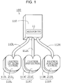
- FIG. 1 illustrates the structure of a living body information measurement apparatus 100 according to an embodiment of the present invention.
- the living body information measurement apparatus 100 includes a control device 110, a C pad 111C, a L pad 111L, a R pad 111R, a C wiring line 112C, a L wiring line 112L, and a R wiring line 112R.
- the C pad 111C includes a flat-plate-shaped C insulator 113C and a flat-plate-shaped first electrode 211C (also referred to as a common electrode, and referred to below as a C electrode 211C in some cases) that is stuck to a surface of the C insulator 113C.
- the L pad 111L includes a flat-plate-shaped L insulator 113L and a left second electrode 211L (referred to below as a L electrode 211L in some cases) that is stuck to a surface of the L insulator 113L.
- the R pad 111R includes a flat-plate-shaped R insulator 113R and a right second electrode 211R (referred to below as a R electrode 211R in some cases) that is stuck to a surface of the R insulator 113R.
- the C electrode 211C, the L electrode 211L, and the R electrode 211R are not distinguished from each other and are referred to electrodes 211 in some cases.
- Each of the electrodes 211 is composed of a conductive material such as a metal and exposed to the outside so as to be capable of coming into contact with a living body.
- the control device 110 accommodates components that are included in an electrical system described later.
- the C wiring line 112C connects the control device 110 and the C electrode 211C to each other.
- the L wiring line 112L connects the control device 110 and the L electrode 211L to each other.
- the R wiring line 112R electrically connects the control device 110 and the R electrode 211R to each other.
- the living body information measurement apparatus 100 carries out living body information measurement to measure living body information and wearing state detection to detect a wearing state of one or more electrodes 211 against the living body on the basis of an electrical signal from the living body.
- An example of the living body is a human body.
- An example of the living body information is an electrocardiogram.
- the living body information measurement apparatus 100 operates by using the power of a built-in battery not illustrated.
- the C electrode 211C, the L electrode 211L, and the R electrode 211R are disposed on a skin of the human body near the heart.
- the C electrode 211C is disposed nearest to the heart between the L electrode 211L and the R electrode 211R.
- the L electrode 211L and the R electrode 211R are disposed symmetrically about the C electrode 211C when being properly worn on the living body.
- a voltage waveform between the C electrode 211C and the L electrode 211L is detected.
- a voltage waveform between the C electrode 211C and the R electrode 211R is detected. The difference between the two detected voltage waveforms represents electrocardiogram information of the human body.
- Fig. 2 is a functional block diagram of a control system of the living body information measurement apparatus 100 illustrated in Fig. 1 .
- the living body information measurement apparatus 100 includes, for example, an accelerometer 11, a living body tactile sensor 13, a wearing determination unit 21, a kinematic analysis unit 23, a communication unit 25, a peripheral circuit 27, a control unit 29, and a power supply unit 31.
- the accelerometer 11, the living body tactile sensor 13, and the wearing determination unit 21 are included in a wearing determination apparatus 1 according to the embodiment of the present invention.
- the accelerometer 11 is installed, for example, in a control device 100 illustrated in Fig. 1 .
- the accelerometer 11 generates an acceleration signal.
- the accelerometer 11 outputs a first interrupt signal S1 to the control unit 29 when an acceleration is detected in a state where no acceleration is created for a certain period of time.
- the control unit 29 outputs a first interrupt signal S11 depending on the first interrupt signal S1 to the living body tactile sensor 13 and the wearing determination unit 21.
- the accelerometer 11 outputs a second interrupt signal S2 to the control unit 29 when no acceleration is detected for a certain period of time after the acceleration is detected.
- the control unit 29 outputs a second interrupt signal S21 depending on the second interrupt signal S2 to the living body tactile sensor 13 and the wearing determination unit 21.
- the living body tactile sensor 13 includes the C pad 111C, the L pad 111L, and the R pad 111R, which are living body contact portions that come into contact with the living body, illustrated in Fig. 1 .
- the living body tactile sensor 13 also includes a signal applicator (not illustrated) and a signal amplifier (not illustrated).
- the living body tactile sensor 13 can select a wakeup mode in which electrical characteristics of each living body contact portion are detected and a sleep mode in which the power consumption is lower than that in the wakeup mode.
- the living body tactile sensor 13 When the first interrupt signal S11 is inputted from the control unit 29 in the sleep mode, the living body tactile sensor 13 performs its own wakeup process to switch to the wakeup mode.
- the living body tactile sensor 13 When the second interrupt signal S21 is inputted from the control unit 29 in the wakeup mode, the living body tactile sensor 13 performs its own sleep process to switch to the sleep mode.
- the wearing determination unit 21 determines whether the living body information measurement apparatus 100 is worn on the living body on the basis of the signal from the living body tactile sensor 13.
- the wearing determination unit 21 determines that the living body information measurement apparatus 100 is worn on the living body and the kinematic analysis unit 23, the communication unit 25, and the peripheral circuit 27 are in the sleep mode, the wearing determination unit 21 transmits a third interrupt signal S3 to the control unit 29.
- the control unit 29 outputs a third interrupt signal S31 depending on the third interrupt signal S3 to the kinematic analysis unit 23, the communication unit 25, and the peripheral circuit 27, which perform their own wakeup process.
- the wearing determination unit 21 may make a wearing determination by using the signal from the accelerometer 11 in addition to the signal from the living body tactile sensor 13.
- the wearing determination with the signal from the living body tactile sensor 13 can be made more accurately than that with the acceleration signal from the accelerometer 11.
- the wearing determination unit 21 determines that the living body information measurement apparatus 100 is not worn on the living body
- the wearing determination unit 21 outputs a fourth interrupt signal S4 to the control unit 29.
- the control unit 29 outputs a fourth interrupt signal S41 depending on the fourth interrupt signal S4 to the kinematic analysis unit 23, the communication unit 25, and the peripheral circuit 27. Consequently, the kinematic analysis unit 23, the communication unit 25, and the peripheral circuit 27 perform their own sleep process.
- the power consumption of the living body tactile sensor 13 and the wearing determination unit 21 in the wakeup mode is higher than the power consumption of the accelerometer 11.
- the kinematic analysis unit 23 performs a kinematic analysis process of a wearer of the living body information measurement apparatus 100 on the basis of the signals from the accelerometer 11 and the living body tactile sensor 13.
- the kinematic analysis unit 23 When the third interrupt signal S31 is inputted from the control unit 29, the kinematic analysis unit 23 performs its own wakeup process. When the fourth interrupt signal S41 is inputted from the control unit 29, the kinematic analysis unit 23 performs its own sleep process.
- the communication unit 25 has a communication function of transmitting, for example, the result of the wearing determination of the wearing determination unit 21 and the result of kinematic analysis of the kinematic analysis unit 23 to a predetermined communication device.
- the communication unit 25 When the third interrupt signal S31 is inputted from the control unit 29, the communication unit 25 performs its own wakeup process. When the fourth interrupt signal S41 is inputted from the control unit 29, the communication unit 25 performs its own sleep process.
- the peripheral circuit 27 has a function of performing processes such as a process of monitoring supply voltage of the power supply unit and a process of making a LED indicator capable of being emitted.
- the peripheral circuit 27 When the third interrupt signal S31 is inputted from the control unit 29, the peripheral circuit 27 performs its own wakeup process. When the fourth interrupt signal S41 is inputted from the control unit 29, the peripheral circuit 27 performs its own sleep process.
- the power consumption of the kinematic analysis unit 23, the communication unit 25, and the peripheral circuit 27 in the wakeup mode is higher than, but may be equal to or lower than, the power consumption of the living body tactile sensor 13 and the wearing determination unit 21 in the wakeup mode.
- Fig. 3 is a flowchart for describing the wakeup process of the living body information measurement apparatus 100 illustrated in Fig. 1 .
- the accelerometer 11 determines whether an acceleration is created in a state where the living body information measurement apparatus 100 is not accelerated for a certain period of time. In the case of a positive determination, the flow proceeds to a step ST12. In the case of a negative determination, the determination is repeated.
- the accelerometer 11 outputs the first interrupt signal S1 to the control unit 29.
- the control unit 29 outputs the first interrupt signal S11 depending on the first interrupt signal S1 to the living body tactile sensor 13 and the wearing determination unit 21.
- the living body tactile sensor 13 When the first interrupt signal S11 is inputted from the control unit 29 in the sleep mode, the living body tactile sensor 13 performs its own wakeup process to switch to the wakeup mode.
- the wearing determination unit 21 performs its own wakeup process to switch to the wakeup mode.
- the wearing determination unit 21 performs a wearing determination process to determine whether the living body information measurement apparatus 100 is worn on the living body on the basis of the signal of the living body tactile sensor 13.
- the flow proceeds to a step ST5.
- the flow proceeds to a step ST6.
- the wearing determination unit 21 outputs the third interrupt signal S3 to the control unit 29.
- the control unit 29 outputs the third interrupt signal S31 depending on the third interrupt signal S3 to the kinematic analysis unit 23, the communication unit 25, and the peripheral circuit 27.
- the kinematic analysis unit 23, the communication unit 25, and the peripheral circuit 27 perform the wakeup process in response to the third interrupt signal S31 to switch to the wakeup mode.
- the wearing determination unit 21 performs its own sleep process to switch to the sleep mode.
- Fig. 4 is a flowchart for describing the primary wakeup process at the step ST5 illustrated in Fig. 3 .
- the kinematic analysis unit 23 performs the wakeup process on the basis of the third interrupt signal S31 from the control unit 29 to switch to the wakeup mode (step ST11). Consequently, the kinematic analysis unit 23 performs the kinematic analysis process of the wearer of the living body information measurement apparatus 100 on the basis of the signals from the accelerometer 11 and the living body tactile sensor 13.
- the communication unit 25 performs the wakeup process on the basis of the third interrupt signal S31 from the control unit 29 to switch to the wakeup mode (step ST12). Consequently, the communication unit 25 performs a communication process of transmitting, for example, the result of the wearing determination of the wearing determination unit 21 and the result of the kinematic analysis of the kinematic analysis unit 23 to a predetermined communication device.
- the peripheral circuit 27 performs the wakeup process on the basis of the third interrupt signal S31 from the control unit 29 to switch to the wakeup mode (step ST13).
- the wearing determination unit 21 performs its own sleep process to switch to the sleep mode.
- Fig. 5 is a flowchart for describing the sleep process of the living body information measurement apparatus 100 illustrated in Fig. 1 .
- the flow proceeds to a step ST22. When this is not the case, the determination is repeated.
- the accelerometer 11 outputs the second interrupt signal S2 to the control unit 29.
- the control unit 29 outputs the second interrupt signal S21 depending on the second interrupt signal S2 to the living body tactile sensor 13, the wearing determination unit 21, the kinematic analysis unit 23, the communication unit 25, and the peripheral circuit 27.
- the living body tactile sensor 13, the wearing determination unit 21, the kinematic analysis unit 23, the communication unit 25, and the peripheral circuit 27 perform the sleep process in response to the second interrupt signal S21 to switch to the sleep mode.
- the living body information measurement apparatus 100 performs the wakeup process of the living body tactile sensor 13 and the wearing determination unit 21 when the accelerometer 11 detects the acceleration. Accordingly, the living body tactile sensor 13 and the wearing determination unit 21 can be in the sleep mode while the accelerometer 11 detects no acceleration, and power saving can be achieved.
- the living body information measurement apparatus 100 can make the wearing determination by the living body tactile sensor 13 and the wearing determination unit 21 in addition to detection of the acceleration by the accelerometer 11. Accordingly, the wakeup process of the kinematic analysis unit 23, the communication unit 25, and the peripheral circuit 27, which are the other circuit blocks, can be performed under the condition that wearing on the living body is determined. The wakeup process of the circuit blocks can be prevented from being performed in a non-wearing state. This also achieves power saving.
- the living body information measurement apparatus 100 can perform the wakeup process of the kinematic analysis unit 23, the communication unit 25, and the peripheral circuit 27 under the condition that the accelerometer 11 detects the acceleration in addition to the wearing determination by the kinematic analysis unit 23 and can prevent the wakeup process from being unnecessarily performed when a conductor comes into contact with the R electrode 211R, the L electrode 211L, or the C electrode 211C, which is the living body contact portion. This also achieves power saving.
- the living body information measurement apparatus 100 performs the sleep process to switch itself from the wakeup mode to the sleep mode when the wearing determination unit 21 determines the non-wearing state. This enables the wearing determination unit 21 to be in the sleep mode in the non-wearing state and achieves power saving.
- the living body information measurement apparatus 100 outputs the second interrupt signal when the accelerometer 11 detects no acceleration for a certain period of time. In response to this, the living body tactile sensor 13 and the wearing determination unit 21 perform the sleep process to switch themselves from the wakeup mode to the sleep mode. This also achieves power saving.
- the present invention is not limited to the above embodiment.
- a glasses electronic device is described as an example of an electronic device according to the present invention.
- another electronic device that is worn on the human body such as a list band or a watch may be acceptable.
- the human body is described as an example of the living body.
- the case of wearing on the living body of, for example, an animal such as a pet other than the human body is also acceptable.
- the living body tactile sensor 13 and the wearing determination unit 21 are different modules but may be a single module.
- the kinematic analysis unit 23, the communication unit 25, and the peripheral circuit 27 are described as examples of circuit blocks according to the present invention. However, other circuits may be acceptable.
- the present invention can be applied to various living body information measurement apparatuses that are worn on the living body, for example, living body information measurement apparatuses that are used for electrocardiogram measurement, eye potential measurement, and muscle potential measurement.
Landscapes
- Engineering & Computer Science (AREA)
- Theoretical Computer Science (AREA)
- General Engineering & Computer Science (AREA)
- Physics & Mathematics (AREA)
- General Physics & Mathematics (AREA)
- Computer Hardware Design (AREA)
- Human Computer Interaction (AREA)
- Health & Medical Sciences (AREA)
- Life Sciences & Earth Sciences (AREA)
- Biophysics (AREA)
- Surgery (AREA)
- Pathology (AREA)
- Biomedical Technology (AREA)
- Heart & Thoracic Surgery (AREA)
- Medical Informatics (AREA)
- Molecular Biology (AREA)
- Cardiology (AREA)
- Animal Behavior & Ethology (AREA)
- General Health & Medical Sciences (AREA)
- Public Health (AREA)
- Veterinary Medicine (AREA)
- Measurement Of The Respiration, Hearing Ability, Form, And Blood Characteristics Of Living Organisms (AREA)
- Power Sources (AREA)
Abstract
Description
- The present invention relates to a wearing determination apparatus and an electronic device that uses the wearing determination apparatus.
-
PTL 1 discloses a technique for reducing a power consumption in a battery-powered electronic device when not in use. - The electronic device detects whether a hand of a user approaches in a sleep mode and becomes active when it is determined that the hand approaches.
-
PTL 1 also discloses that a wakeup process is performed when an acceleration is detected in the sleep mode. - PTL 1: Japanese Unexamined Patent Application Publication No.
2004-240971 - As disclosed in
PTL 1 described above, however, in the case where the wakeup process from sleep is performed only due to approach of the user or wearing determination, it is necessary to continue the wearing determination or approach with a relatively high power consumption during a sleep period, and the power consumption is high. In some cases where a conductor other than a living body approaches or comes into contact, the wakeup process is unnecessarily performed. - In the case where the wakeup process is started only under the condition that the electronic device is accelerated, the wakeup process is performed even when the electronic device is not worn on the living body and the electronic device vibrates.
- The present invention has been accomplished in view of such circumstances, and an object of the present invention is to provide a wearing determination apparatus that can accurately determine whether an electronic device is worn, and the electronic device that achieves power saving by using the wearing determination apparatus.
- In order to solve the above problem of the related art and achieve the above object, a wearing determination apparatus according to the present invention is a wearing determination apparatus configured to be installed in an electronic device configured to be worn on a living body. The wearing determination apparatus includes an accelerometer, a tactile sensor including a living body contact portion configured to come into contact with the living body, the tactile sensor generating a signal in response to contact between the living body contact portion and the living body, and a wearing determination unit configured to determine whether the living body contact portion is in contact with the living body on the basis of a signal from the accelerometer and the tactile sensor. The accelerometer outputs a first interrupt signal when the accelerometer detects an acceleration. The tactile sensor and the wearing determination unit perform a wakeup process to switch themselves from a sleep mode to a wakeup mode in response to the first interrupt signal outputted from the accelerometer.
- With this structure, the wakeup process of the tactile sensor and the wearing determination unit is performed when the accelerometer detects the acceleration. Accordingly, the tactile sensor and the wearing determination unit can be in the sleep mode while the accelerometer detects no acceleration, and power saving can be achieved.
- In addition, with this structure, a wearing determination can be made by the wearing determination unit in addition to detection of the acceleration by the accelerometer. Accordingly, the wakeup process of another circuit block can be performed under the condition that wearing on the living body is determined. The wakeup process of the circuit block can be prevented from being performed in a non-wearing state. This also achieves power saving.
- In addition, with this structure, the wakeup process of the circuit block can be performed under the condition that the accelerometer detects the acceleration in addition to the wearing determination, and the wakeup process can be prevented from being unnecessarily performed when a conductor other than the living body comes into contact with the living body contact portion. This also achieves power saving.
- The wearing determination unit preferably determines whether the living body contact portion is in contact with the living body on the basis of a signal from the tactile sensor after the wakeup process and performs a wakeup process to cause a predetermined circuit block of the electronic device to switch from the sleep mode to the wakeup mode in a case of a positive determination.
- With this structure, the wearing determination can be made by the wearing determination unit in addition to detection of the acceleration by the accelerometer. Accordingly, the wakeup process of another circuit block can be performed under the condition that wearing on the living body is determined. The wakeup process of the circuit block can be prevented from being performed in a non-wearing state. This also achieves power saving.
- The wearing determination unit preferably performs a sleep process to switch itself from the wakeup mode to the sleep mode when the wearing determination unit determines that the living body contact portion is not in contact with the living body.
- With this structure, the wearing determination unit can be in the sleep mode in the non-wearing state and power saving is achieved.
- The accelerometer preferably outputs a second interrupt signal when the accelerometer detects no acceleration for a certain period of time.
- The tactile sensor and the wearing determination unit preferably perform a sleep process to switch themselves from the wakeup mode to the sleep mode in response to the second interrupt signal.
- With this structure, the tactile sensor and the wearing determination unit are in the sleep mode when no acceleration is detected for a certain period of time. This achieves power saving.
- A power consumption of the accelerometer is preferably lower than a power consumption of the tactile sensor and the wearing determination unit in the wakeup mode.
- With this structure, the wearing determination unit and the tactile sensor that have a relatively high power consumption can be in the sleep mode.
- A power consumption of the wearing determination unit in the wakeup mode is preferably lower than a power consumption of the predetermined circuit block in the wakeup mode.
- With this structure, the circuit block that has a relatively high power consumption can be in the sleep mode.
- An electronic device according to the present invention is an electronic device configured to be worn on a living body. The electronic device includes the wearing determination apparatus. The wearing determination apparatus includes an accelerometer, a tactile sensor including a living body contact portion configured to come into contact with the living body, the tactile sensor generating a signal in response to contact between the living body contact portion and the living body, and a wearing determination unit configured to determine whether the living body contact portion is in contact with the living body on the basis of a signal from the accelerometer and the tactile sensor. The accelerometer outputs a first interrupt signal when the accelerometer detects an acceleration. The tactile sensor and the wearing determination unit perform a wakeup process to switch themselves from a sleep mode to a wakeup mode in response to the first interrupt signal outputted from the accelerometer.
- With this structure, the wakeup process of the tactile sensor and the wearing determination unit is performed when the accelerometer detects the acceleration. Accordingly, the tactile sensor and the wearing determination unit can be in the sleep mode while the accelerometer detects no acceleration, and power saving can be achieved.
- In addition, with this structure, the wearing determination can be made by the wearing determination unit in addition to detection of the acceleration by the accelerometer. Accordingly, the wakeup process of another circuit block that is included in the electronic device can be performed under the condition that wearing on the living body is determined. The wakeup process of the circuit block can be prevented from being performed in a non-wearing state. This also achieves power saving.
- In addition, with this structure, the wakeup process of the circuit block can be performed under the condition that the accelerometer detects the acceleration in addition to the wearing determination, and the wakeup process can be prevented from being unnecessarily performed when a conductor other than the living body comes into contact with the living body contact portion. This also achieves power saving.
- The present invention can provide a wearing determination apparatus that can accurately determine whether an electronic device is worn, and the electronic device that achieves power saving by using the wearing determination apparatus.
-
- [
Fig. 1] Fig. 1 illustrates the structure of a living body information measurement apparatus according to an embodiment of the present invention. - [
Fig. 2] Fig. 2 is a functional block diagram of a control system of the living body information measurement apparatus illustrated inFig. 1 . - [
Fig. 3] Fig. 3 is a flowchart for describing a wakeup process of the living body information measurement apparatus illustrated inFig. 1 . - [
Fig. 4] Fig. 4 is a flowchart for describing a primary wakeup process at a step ST5 illustrated inFig. 3 . - [
Fig. 5] Fig. 5 is a flowchart for describing a sleep process of the living body information measurement apparatus illustrated inFig. 1 . - A living body information measurement apparatus according to an embodiment of the present invention will hereinafter be described.
Fig. 1 illustrates the structure of a living bodyinformation measurement apparatus 100 according to an embodiment of the present invention. The living bodyinformation measurement apparatus 100 includes acontrol device 110, aC pad 111C, aL pad 111L, aR pad 111R, aC wiring line 112C, aL wiring line 112L, and aR wiring line 112R. - The
C pad 111C includes a flat-plate-shapedC insulator 113C and a flat-plate-shapedfirst electrode 211C (also referred to as a common electrode, and referred to below as aC electrode 211C in some cases) that is stuck to a surface of theC insulator 113C. TheL pad 111L includes a flat-plate-shaped L insulator 113L and a leftsecond electrode 211L (referred to below as aL electrode 211L in some cases) that is stuck to a surface of theL insulator 113L. TheR pad 111R includes a flat-plate-shapedR insulator 113R and a rightsecond electrode 211R (referred to below as aR electrode 211R in some cases) that is stuck to a surface of theR insulator 113R. In the following description, theC electrode 211C, the L electrode 211L, and theR electrode 211R are not distinguished from each other and are referred to electrodes 211 in some cases. Each of the electrodes 211 is composed of a conductive material such as a metal and exposed to the outside so as to be capable of coming into contact with a living body. - The
control device 110 accommodates components that are included in an electrical system described later. TheC wiring line 112C connects thecontrol device 110 and theC electrode 211C to each other. TheL wiring line 112L connects thecontrol device 110 and theL electrode 211L to each other. TheR wiring line 112R electrically connects thecontrol device 110 and theR electrode 211R to each other. - The living body
information measurement apparatus 100 carries out living body information measurement to measure living body information and wearing state detection to detect a wearing state of one or more electrodes 211 against the living body on the basis of an electrical signal from the living body. An example of the living body is a human body. An example of the living body information is an electrocardiogram. The living bodyinformation measurement apparatus 100 operates by using the power of a built-in battery not illustrated. - The
C electrode 211C, the L electrode 211L, and theR electrode 211R are disposed on a skin of the human body near the heart. TheC electrode 211C is disposed nearest to the heart between the L electrode 211L and theR electrode 211R. The L electrode 211L and theR electrode 211R are disposed symmetrically about theC electrode 211C when being properly worn on the living body. A voltage waveform between the C electrode 211C and theL electrode 211L is detected. In addition, a voltage waveform between the C electrode 211C and theR electrode 211R is detected. The difference between the two detected voltage waveforms represents electrocardiogram information of the human body. -
Fig. 2 is a functional block diagram of a control system of the living bodyinformation measurement apparatus 100 illustrated inFig. 1 . - As illustrated in
Fig. 1 , the living bodyinformation measurement apparatus 100 includes, for example, anaccelerometer 11, a living bodytactile sensor 13, a wearingdetermination unit 21, akinematic analysis unit 23, acommunication unit 25, aperipheral circuit 27, acontrol unit 29, and apower supply unit 31. - The
accelerometer 11, the living bodytactile sensor 13, and the wearingdetermination unit 21 are included in a wearingdetermination apparatus 1 according to the embodiment of the present invention. - The
accelerometer 11 is installed, for example, in acontrol device 100 illustrated inFig. 1 . Theaccelerometer 11 generates an acceleration signal. Theaccelerometer 11 outputs a first interrupt signal S1 to thecontrol unit 29 when an acceleration is detected in a state where no acceleration is created for a certain period of time. - The
control unit 29 outputs a first interrupt signal S11 depending on the first interrupt signal S1 to the living bodytactile sensor 13 and the wearingdetermination unit 21. - The
accelerometer 11 outputs a second interrupt signal S2 to thecontrol unit 29 when no acceleration is detected for a certain period of time after the acceleration is detected. - The
control unit 29 outputs a second interrupt signal S21 depending on the second interrupt signal S2 to the living bodytactile sensor 13 and the wearingdetermination unit 21. - The living body
tactile sensor 13 includes theC pad 111C, theL pad 111L, and theR pad 111R, which are living body contact portions that come into contact with the living body, illustrated inFig. 1 . The living bodytactile sensor 13 also includes a signal applicator (not illustrated) and a signal amplifier (not illustrated). - The living body
tactile sensor 13 can select a wakeup mode in which electrical characteristics of each living body contact portion are detected and a sleep mode in which the power consumption is lower than that in the wakeup mode. - When the first interrupt signal S11 is inputted from the
control unit 29 in the sleep mode, the living bodytactile sensor 13 performs its own wakeup process to switch to the wakeup mode. - When the second interrupt signal S21 is inputted from the
control unit 29 in the wakeup mode, the living bodytactile sensor 13 performs its own sleep process to switch to the sleep mode. - In the wakeup mode, the wearing
determination unit 21 determines whether the living bodyinformation measurement apparatus 100 is worn on the living body on the basis of the signal from the living bodytactile sensor 13. - When the wearing
determination unit 21 determines that the living bodyinformation measurement apparatus 100 is worn on the living body and thekinematic analysis unit 23, thecommunication unit 25, and theperipheral circuit 27 are in the sleep mode, the wearingdetermination unit 21 transmits a third interrupt signal S3 to thecontrol unit 29. Thecontrol unit 29 outputs a third interrupt signal S31 depending on the third interrupt signal S3 to thekinematic analysis unit 23, thecommunication unit 25, and theperipheral circuit 27, which perform their own wakeup process. - The wearing
determination unit 21 may make a wearing determination by using the signal from theaccelerometer 11 in addition to the signal from the living bodytactile sensor 13. The wearing determination with the signal from the living bodytactile sensor 13 can be made more accurately than that with the acceleration signal from theaccelerometer 11. - When the wearing
determination unit 21 determines that the living bodyinformation measurement apparatus 100 is not worn on the living body, the wearingdetermination unit 21 outputs a fourth interrupt signal S4 to thecontrol unit 29. Thecontrol unit 29 outputs a fourth interrupt signal S41 depending on the fourth interrupt signal S4 to thekinematic analysis unit 23, thecommunication unit 25, and theperipheral circuit 27. Consequently, thekinematic analysis unit 23, thecommunication unit 25, and theperipheral circuit 27 perform their own sleep process. - The power consumption of the living body
tactile sensor 13 and the wearingdetermination unit 21 in the wakeup mode is higher than the power consumption of theaccelerometer 11. - The
kinematic analysis unit 23 performs a kinematic analysis process of a wearer of the living bodyinformation measurement apparatus 100 on the basis of the signals from theaccelerometer 11 and the living bodytactile sensor 13. - When the third interrupt signal S31 is inputted from the
control unit 29, thekinematic analysis unit 23 performs its own wakeup process. When the fourth interrupt signal S41 is inputted from thecontrol unit 29, thekinematic analysis unit 23 performs its own sleep process. - The
communication unit 25 has a communication function of transmitting, for example, the result of the wearing determination of the wearingdetermination unit 21 and the result of kinematic analysis of thekinematic analysis unit 23 to a predetermined communication device. - When the third interrupt signal S31 is inputted from the
control unit 29, thecommunication unit 25 performs its own wakeup process. When the fourth interrupt signal S41 is inputted from thecontrol unit 29, thecommunication unit 25 performs its own sleep process. - The
peripheral circuit 27 has a function of performing processes such as a process of monitoring supply voltage of the power supply unit and a process of making a LED indicator capable of being emitted. - When the third interrupt signal S31 is inputted from the
control unit 29, theperipheral circuit 27 performs its own wakeup process. When the fourth interrupt signal S41 is inputted from thecontrol unit 29, theperipheral circuit 27 performs its own sleep process. - The power consumption of the
kinematic analysis unit 23, thecommunication unit 25, and theperipheral circuit 27 in the wakeup mode is higher than, but may be equal to or lower than, the power consumption of the living bodytactile sensor 13 and the wearingdetermination unit 21 in the wakeup mode. - An example of operation related to the wakeup process and the sleep process of the living body
information measurement apparatus 100 will now be described. -
Fig. 3 is a flowchart for describing the wakeup process of the living bodyinformation measurement apparatus 100 illustrated inFig. 1 . - The
accelerometer 11 determines whether an acceleration is created in a state where the living bodyinformation measurement apparatus 100 is not accelerated for a certain period of time. In the case of a positive determination, the flow proceeds to a step ST12. In the case of a negative determination, the determination is repeated. - The
accelerometer 11 outputs the first interrupt signal S1 to thecontrol unit 29. Thecontrol unit 29 outputs the first interrupt signal S11 depending on the first interrupt signal S1 to the living bodytactile sensor 13 and the wearingdetermination unit 21. - When the first interrupt signal S11 is inputted from the
control unit 29 in the sleep mode, the living bodytactile sensor 13 performs its own wakeup process to switch to the wakeup mode. - When the first interrupt signal S11 is inputted from the
control unit 29 in the sleep mode, the wearingdetermination unit 21 performs its own wakeup process to switch to the wakeup mode. - Consequently, the wearing
determination unit 21 performs a wearing determination process to determine whether the living bodyinformation measurement apparatus 100 is worn on the living body on the basis of the signal of the living bodytactile sensor 13. - When the result of the wearing determination process of the wearing
determination unit 21 is the positive determination, that is, a wearing state, the flow proceeds to a step ST5. In the case of the negative determination, the flow proceeds to a step ST6. - The wearing
determination unit 21 outputs the third interrupt signal S3 to thecontrol unit 29. - The
control unit 29 outputs the third interrupt signal S31 depending on the third interrupt signal S3 to thekinematic analysis unit 23, thecommunication unit 25, and theperipheral circuit 27. - The
kinematic analysis unit 23, thecommunication unit 25, and theperipheral circuit 27 perform the wakeup process in response to the third interrupt signal S31 to switch to the wakeup mode. - The wearing
determination unit 21 performs its own sleep process to switch to the sleep mode. -
Fig. 4 is a flowchart for describing the primary wakeup process at the step ST5 illustrated inFig. 3 . - As illustrated in
Fig. 4 , thekinematic analysis unit 23 performs the wakeup process on the basis of the third interrupt signal S31 from thecontrol unit 29 to switch to the wakeup mode (step ST11). Consequently, thekinematic analysis unit 23 performs the kinematic analysis process of the wearer of the living bodyinformation measurement apparatus 100 on the basis of the signals from theaccelerometer 11 and the living bodytactile sensor 13. - Subsequently, the
communication unit 25 performs the wakeup process on the basis of the third interrupt signal S31 from thecontrol unit 29 to switch to the wakeup mode (step ST12). Consequently, thecommunication unit 25 performs a communication process of transmitting, for example, the result of the wearing determination of the wearingdetermination unit 21 and the result of the kinematic analysis of thekinematic analysis unit 23 to a predetermined communication device. - Subsequently, the
peripheral circuit 27 performs the wakeup process on the basis of the third interrupt signal S31 from thecontrol unit 29 to switch to the wakeup mode (step ST13). - The wearing
determination unit 21 performs its own sleep process to switch to the sleep mode. -
Fig. 5 is a flowchart for describing the sleep process of the living bodyinformation measurement apparatus 100 illustrated inFig. 1 . - When the
accelerometer 11 determines that no acceleration is detected for a certain period of time after the acceleration is detected, the flow proceeds to a step ST22. When this is not the case, the determination is repeated. - The
accelerometer 11 outputs the second interrupt signal S2 to thecontrol unit 29. - The
control unit 29 outputs the second interrupt signal S21 depending on the second interrupt signal S2 to the living bodytactile sensor 13, the wearingdetermination unit 21, thekinematic analysis unit 23, thecommunication unit 25, and theperipheral circuit 27. - The living body
tactile sensor 13, the wearingdetermination unit 21, thekinematic analysis unit 23, thecommunication unit 25, and theperipheral circuit 27 perform the sleep process in response to the second interrupt signal S21 to switch to the sleep mode. - As described above, the living body
information measurement apparatus 100 performs the wakeup process of the living bodytactile sensor 13 and the wearingdetermination unit 21 when theaccelerometer 11 detects the acceleration. Accordingly, the living bodytactile sensor 13 and the wearingdetermination unit 21 can be in the sleep mode while theaccelerometer 11 detects no acceleration, and power saving can be achieved. - The living body
information measurement apparatus 100 can make the wearing determination by the living bodytactile sensor 13 and the wearingdetermination unit 21 in addition to detection of the acceleration by theaccelerometer 11. Accordingly, the wakeup process of thekinematic analysis unit 23, thecommunication unit 25, and theperipheral circuit 27, which are the other circuit blocks, can be performed under the condition that wearing on the living body is determined. The wakeup process of the circuit blocks can be prevented from being performed in a non-wearing state. This also achieves power saving. - The living body
information measurement apparatus 100 can perform the wakeup process of thekinematic analysis unit 23, thecommunication unit 25, and theperipheral circuit 27 under the condition that theaccelerometer 11 detects the acceleration in addition to the wearing determination by thekinematic analysis unit 23 and can prevent the wakeup process from being unnecessarily performed when a conductor comes into contact with theR electrode 211R, the L electrode 211L, or theC electrode 211C, which is the living body contact portion. This also achieves power saving. - The living body
information measurement apparatus 100 performs the sleep process to switch itself from the wakeup mode to the sleep mode when the wearingdetermination unit 21 determines the non-wearing state. This enables the wearingdetermination unit 21 to be in the sleep mode in the non-wearing state and achieves power saving. - The living body
information measurement apparatus 100 outputs the second interrupt signal when theaccelerometer 11 detects no acceleration for a certain period of time. In response to this, the living bodytactile sensor 13 and the wearingdetermination unit 21 perform the sleep process to switch themselves from the wakeup mode to the sleep mode. This also achieves power saving. - The present invention is not limited to the above embodiment.
- That is, a person skilled in the art may make various modifications, combinations, sub-combinations, and alternations regarding the components according to the above embodiment within the technical range or the equivalent range of the present invention.
- For example, according to the above embodiment, a glasses electronic device is described as an example of an electronic device according to the present invention. However, another electronic device that is worn on the human body such as a list band or a watch may be acceptable.
- According to the above embodiment, the human body is described as an example of the living body. However, the case of wearing on the living body of, for example, an animal such as a pet other than the human body is also acceptable.
- In an example described according to the above embodiment, the living body
tactile sensor 13 and the wearingdetermination unit 21 are different modules but may be a single module. - According to the above embodiment, the
kinematic analysis unit 23, thecommunication unit 25, and theperipheral circuit 27 are described as examples of circuit blocks according to the present invention. However, other circuits may be acceptable. - The present invention can be applied to various living body information measurement apparatuses that are worn on the living body, for example, living body information measurement apparatuses that are used for electrocardiogram measurement, eye potential measurement, and muscle potential measurement.
-
- 1
- wearing determination apparatus
- 11
- accelerometer
- 13
- living body tactile sensor
- 21
- wearing determination unit
- 23
- kinematic analysis unit
- 25
- communication unit
- 27
- peripheral circuit
- 29
- control unit
- 31
- power supply unit
- 100
- living body information measurement apparatus
- 111C
- C pad
- 111L
- L pad
- 111R
- R pad
- 113C
- C insulator
- 113L
- L insulator
- 113R
- R insulator
- 211C
- C electrode
- 211L
- L electrode
- 211R
- R electrode
Claims (7)
- A wearing determination apparatus configured to be installed in an electronic device configured to be worn on a living body, the wearing determination apparatus comprising:an accelerometer;a tactile sensor including a living body contact portion configured to come into contact with the living body, the tactile sensor generating a signal in response to contact between the living body contact portion and the living body; anda wearing determination unit configured to determine whether the living body contact portion is in contact with the living body on the basis of a signal from the accelerometer and the tactile sensor,wherein the accelerometer outputs a first interrupt signal when the accelerometer detects an acceleration, andwherein the tactile sensor and the wearing determination unit perform a wakeup process to switch themselves from a sleep mode to a wakeup mode in response to the first interrupt signal outputted from the accelerometer.
- The wearing determination apparatus according to Claim 1,
wherein the wearing determination unit determines whether the living body contact portion is in contact with the living body on the basis of the signal from the tactile sensor after the wakeup process and performs a wakeup process to cause a predetermined circuit block of the electronic device to switch from the sleep mode to the wakeup mode in a case of a positive determination. - The wearing determination apparatus according to Claim 1,
wherein the wearing determination unit performs a sleep process to switch itself from the wakeup mode to the sleep mode when the wearing determination unit determines that the living body contact portion is not in contact with the living body. - The wearing determination apparatus according to Claim 1,
wherein the accelerometer outputs a second interrupt signal when the accelerometer detects no acceleration for a certain period of time, and
wherein the tactile sensor and the wearing determination unit perform a sleep process to switch themselves from the wakeup mode to the sleep mode in response to the second interrupt signal. - The wearing determination apparatus according to Claim 1,
wherein a power consumption of the accelerometer is lower than a power consumption of the tactile sensor and the wearing determination unit in the wakeup mode. - The wearing determination apparatus according to Claim 2,
wherein a power consumption of the wearing determination unit in the wakeup mode is lower than a power consumption of the predetermined circuit block in the wakeup mode. - An electronic device configured to be worn on a living body, the electronic device comprising:a wearing determination apparatus that includes an accelerometer,a tactile sensor including a living body contact portion configured to come into contact with the living body, the tactile sensor generating a signal in response to contact between the living body contact portion and the living body, anda wearing determination unit configured to determine whether the living body contact portion is in contact with the living body on the basis of a signal from the accelerometer and the tactile sensor,wherein the accelerometer outputs a first interrupt signal when the accelerometer detects an acceleration, andwherein the tactile sensor and the wearing determination unit perform a wakeup process to switch themselves from a sleep mode to a wakeup mode in response to the first interrupt signal outputted from the accelerometer.
Applications Claiming Priority (2)
| Application Number | Priority Date | Filing Date | Title |
|---|---|---|---|
| JP2017028540 | 2017-02-17 | ||
| PCT/JP2018/003645 WO2018150914A1 (en) | 2017-02-17 | 2018-02-02 | Wearing determination device and electronic device |
Publications (2)
| Publication Number | Publication Date |
|---|---|
| EP3584673A1 true EP3584673A1 (en) | 2019-12-25 |
| EP3584673A4 EP3584673A4 (en) | 2020-12-02 |
Family
ID=63170200
Family Applications (1)
| Application Number | Title | Priority Date | Filing Date |
|---|---|---|---|
| EP18753528.1A Withdrawn EP3584673A4 (en) | 2017-02-17 | 2018-02-02 | WEARING DEVICE AND ELECTRONIC DEVICE |
Country Status (5)
| Country | Link |
|---|---|
| US (1) | US20190324520A1 (en) |
| EP (1) | EP3584673A4 (en) |
| JP (1) | JP6692938B2 (en) |
| CN (1) | CN110192167A (en) |
| WO (1) | WO2018150914A1 (en) |
Families Citing this family (6)
| Publication number | Priority date | Publication date | Assignee | Title |
|---|---|---|---|---|
| EP4610782A3 (en) | 2017-10-26 | 2025-10-22 | Verily Life Sciences LLC | Two-phase deployment-initiated wakeup mechanism for body-mountable electronic device |
| AU2019362849B2 (en) | 2018-10-16 | 2025-06-05 | Dana-Farber Cancer Institute, Inc. | Azaindole inhibitors of wild-type and mutant forms of LRRK2 |
| US11520402B2 (en) | 2018-10-19 | 2022-12-06 | Sony Interactive Entertainment Inc. | Control apparatus for controller device |
| JP2022162883A (en) * | 2021-04-13 | 2022-10-25 | 株式会社ダイヘン | Wire drop detector |
| CN116491880A (en) * | 2023-06-12 | 2023-07-28 | 深圳市科曼医疗设备有限公司 | Endoscope control method, device, computer equipment and storage medium |
| KR20250132204A (en) * | 2024-02-28 | 2025-09-04 | 삼성전자주식회사 | Cotrol system and control mehtod for wearable device |
Family Cites Families (8)
| Publication number | Priority date | Publication date | Assignee | Title |
|---|---|---|---|---|
| US7199783B2 (en) | 2003-02-07 | 2007-04-03 | Avago Technologies Ecbu Ip (Singapore) Pte. Ltd. | Wake-up detection method and apparatus embodying the same |
| JP4822208B2 (en) * | 2006-02-08 | 2011-11-24 | セイコーインスツル株式会社 | Motion measurement device |
| JP2013003911A (en) * | 2011-06-17 | 2013-01-07 | Sony Corp | Electronic device, method for controlling electronic device and program |
| US10463300B2 (en) * | 2011-09-19 | 2019-11-05 | Dp Technologies, Inc. | Body-worn monitor |
| US9554747B2 (en) * | 2013-08-26 | 2017-01-31 | EveryFit, Inc. | Power efficient system and method for measuring physical activity in resource constrained devices |
| JP2016012339A (en) * | 2014-06-02 | 2016-01-21 | セイコーエプソン株式会社 | Information processing apparatus, printing apparatus, and control method |
| JPWO2016194772A1 (en) * | 2015-05-29 | 2018-03-01 | アルプス電気株式会社 | Wear determination apparatus, glasses-type electronic device, wear determination method, and program |
| KR102354586B1 (en) * | 2015-08-11 | 2022-01-24 | 삼성전자주식회사 | Method for controlling according to state and electronic device thereof |
-
2018
- 2018-02-02 CN CN201880007429.XA patent/CN110192167A/en not_active Withdrawn
- 2018-02-02 EP EP18753528.1A patent/EP3584673A4/en not_active Withdrawn
- 2018-02-02 WO PCT/JP2018/003645 patent/WO2018150914A1/en not_active Ceased
- 2018-02-02 JP JP2018568111A patent/JP6692938B2/en active Active
-
2019
- 2019-07-02 US US16/460,771 patent/US20190324520A1/en not_active Abandoned
Also Published As
| Publication number | Publication date |
|---|---|
| WO2018150914A1 (en) | 2018-08-23 |
| JP6692938B2 (en) | 2020-05-13 |
| US20190324520A1 (en) | 2019-10-24 |
| JPWO2018150914A1 (en) | 2019-11-07 |
| CN110192167A (en) | 2019-08-30 |
| EP3584673A4 (en) | 2020-12-02 |
Similar Documents
| Publication | Publication Date | Title |
|---|---|---|
| US20190324520A1 (en) | Wearing determination apparatus and electronic device | |
| CA2792498A1 (en) | A two part eeg monitor with databus and method of communicating between the parts | |
| US11670949B2 (en) | Bio-signal measuring device | |
| US9138592B2 (en) | Defibrillation system and method and defibrillator electrode device | |
| AU2003238115A1 (en) | Method and outfit for measuring of action of muscles of body | |
| CN105023392A (en) | Intelligent bracelet with life alarm function and system thereof | |
| KR20160044811A (en) | Wearable sensor to monitor bio signal and method to monitor bio signal using wearable device | |
| US20100324404A1 (en) | Icg/ecg monitoring apparatus | |
| KR20170093122A (en) | Technologies for biofeedback electrode contact monitoring | |
| US20180150126A1 (en) | Detecting Wearing State of Wearable Devices Using Body Capacitance | |
| US20140100707A1 (en) | Health care device and power management method therefor | |
| US20200139116A1 (en) | Electrical treatment device, electronic device, and terminal device | |
| CN110115560A (en) | Eye tool external member and signal processing unit | |
| US9470704B2 (en) | Wearable motion sensing device | |
| KR101998066B1 (en) | Signal processing device without mechanical switch for on/off operation | |
| US20190307402A1 (en) | Biological information measurement apparatus, method for controlling the same, and recording medium | |
| CN110123312B (en) | Wearable equipment and electrocardio detects accessory thereof | |
| CN206119400U (en) | Multi -functional intelligent bracelet | |
| US11185284B2 (en) | Wearable electrocardiogram device | |
| CN108236463A (en) | Use the health monitoring systems of tack formula wearable device | |
| KR101440051B1 (en) | Apparatus for Measuring Bioelectric Signal | |
| JP2018133791A (en) | Communication controller and electronic apparatus | |
| JP2022129166A (en) | Biological information measurement device and biological information measurement system | |
| CN108030511A (en) | The portable ultrasonic equipment of alternative charging system | |
| KR20210079231A (en) | Conductive Fabric Area Network |
Legal Events
| Date | Code | Title | Description |
|---|---|---|---|
| STAA | Information on the status of an ep patent application or granted ep patent |
Free format text: STATUS: THE INTERNATIONAL PUBLICATION HAS BEEN MADE |
|
| PUAI | Public reference made under article 153(3) epc to a published international application that has entered the european phase |
Free format text: ORIGINAL CODE: 0009012 |
|
| STAA | Information on the status of an ep patent application or granted ep patent |
Free format text: STATUS: REQUEST FOR EXAMINATION WAS MADE |
|
| 17P | Request for examination filed |
Effective date: 20190618 |
|
| AK | Designated contracting states |
Kind code of ref document: A1 Designated state(s): AL AT BE BG CH CY CZ DE DK EE ES FI FR GB GR HR HU IE IS IT LI LT LU LV MC MK MT NL NO PL PT RO RS SE SI SK SM TR |
|
| AX | Request for extension of the european patent |
Extension state: BA ME |
|
| DAV | Request for validation of the european patent (deleted) | ||
| DAX | Request for extension of the european patent (deleted) | ||
| A4 | Supplementary search report drawn up and despatched |
Effective date: 20201029 |
|
| RIC1 | Information provided on ipc code assigned before grant |
Ipc: G06F 1/3231 20190101ALI20201023BHEP Ipc: A61B 5/0488 20060101ALN20201023BHEP Ipc: G06F 1/16 20060101ALI20201023BHEP Ipc: G06F 1/3215 20190101ALI20201023BHEP Ipc: A61B 5/00 20060101ALI20201023BHEP Ipc: A61B 5/0496 20060101ALN20201023BHEP Ipc: A61B 5/0404 20060101AFI20201023BHEP |
|
| STAA | Information on the status of an ep patent application or granted ep patent |
Free format text: STATUS: THE APPLICATION HAS BEEN WITHDRAWN |
|
| 18W | Application withdrawn |
Effective date: 20210519 |