EP3584536B1 - Terrestrial observation apparatus with pose determining functionality - Google Patents
Terrestrial observation apparatus with pose determining functionality Download PDFInfo
- Publication number
- EP3584536B1 EP3584536B1 EP18178464.6A EP18178464A EP3584536B1 EP 3584536 B1 EP3584536 B1 EP 3584536B1 EP 18178464 A EP18178464 A EP 18178464A EP 3584536 B1 EP3584536 B1 EP 3584536B1
- Authority
- EP
- European Patent Office
- Prior art keywords
- observation device
- image
- terrain
- camera
- dtm
- Prior art date
- Legal status (The legal status is an assumption and is not a legal conclusion. Google has not performed a legal analysis and makes no representation as to the accuracy of the status listed.)
- Active
Links
Images


Classifications
-
- G—PHYSICS
- G01—MEASURING; TESTING
- G01C—MEASURING DISTANCES, LEVELS OR BEARINGS; SURVEYING; NAVIGATION; GYROSCOPIC INSTRUMENTS; PHOTOGRAMMETRY OR VIDEOGRAMMETRY
- G01C19/00—Gyroscopes; Turn-sensitive devices using vibrating masses; Turn-sensitive devices without moving masses; Measuring angular rate using gyroscopic effects
- G01C19/02—Rotary gyroscopes
-
- G—PHYSICS
- G01—MEASURING; TESTING
- G01C—MEASURING DISTANCES, LEVELS OR BEARINGS; SURVEYING; NAVIGATION; GYROSCOPIC INSTRUMENTS; PHOTOGRAMMETRY OR VIDEOGRAMMETRY
- G01C21/00—Navigation; Navigational instruments not provided for in groups G01C1/00 - G01C19/00
- G01C21/005—Navigation; Navigational instruments not provided for in groups G01C1/00 - G01C19/00 with correlation of navigation data from several sources, e.g. map or contour matching
-
- G—PHYSICS
- G01—MEASURING; TESTING
- G01C—MEASURING DISTANCES, LEVELS OR BEARINGS; SURVEYING; NAVIGATION; GYROSCOPIC INSTRUMENTS; PHOTOGRAMMETRY OR VIDEOGRAMMETRY
- G01C21/00—Navigation; Navigational instruments not provided for in groups G01C1/00 - G01C19/00
- G01C21/04—Navigation; Navigational instruments not provided for in groups G01C1/00 - G01C19/00 by terrestrial means
- G01C21/06—Navigation; Navigational instruments not provided for in groups G01C1/00 - G01C19/00 by terrestrial means involving measuring of drift angle; involving correction for drift
-
- G—PHYSICS
- G01—MEASURING; TESTING
- G01C—MEASURING DISTANCES, LEVELS OR BEARINGS; SURVEYING; NAVIGATION; GYROSCOPIC INSTRUMENTS; PHOTOGRAMMETRY OR VIDEOGRAMMETRY
- G01C21/00—Navigation; Navigational instruments not provided for in groups G01C1/00 - G01C19/00
- G01C21/04—Navigation; Navigational instruments not provided for in groups G01C1/00 - G01C19/00 by terrestrial means
- G01C21/08—Navigation; Navigational instruments not provided for in groups G01C1/00 - G01C19/00 by terrestrial means involving use of the magnetic field of the earth
-
- G—PHYSICS
- G01—MEASURING; TESTING
- G01C—MEASURING DISTANCES, LEVELS OR BEARINGS; SURVEYING; NAVIGATION; GYROSCOPIC INSTRUMENTS; PHOTOGRAMMETRY OR VIDEOGRAMMETRY
- G01C21/00—Navigation; Navigational instruments not provided for in groups G01C1/00 - G01C19/00
- G01C21/20—Instruments for performing navigational calculations
-
- G—PHYSICS
- G01—MEASURING; TESTING
- G01C—MEASURING DISTANCES, LEVELS OR BEARINGS; SURVEYING; NAVIGATION; GYROSCOPIC INSTRUMENTS; PHOTOGRAMMETRY OR VIDEOGRAMMETRY
- G01C9/00—Measuring inclination, e.g. by clinometers, by levels
- G01C9/02—Details
- G01C9/08—Means for compensating acceleration forces due to movement of instrument
-
- G—PHYSICS
- G02—OPTICS
- G02B—OPTICAL ELEMENTS, SYSTEMS OR APPARATUS
- G02B23/00—Telescopes, e.g. binoculars; Periscopes; Instruments for viewing the inside of hollow bodies; Viewfinders; Optical aiming or sighting devices
- G02B23/16—Housings; Caps; Mountings; Supports, e.g. with counterweight
- G02B23/18—Housings; Caps; Mountings; Supports, e.g. with counterweight for binocular arrangements
Definitions
- the invention relates to an observation device with a position determination functionality for the highly accurate determination of the spatial location and thus the position and orientation (e.g. Euler angle: azimuth, elevation and roll angle) of the observation device by evaluating a recorded camera image of the terrain surrounding the camera using the three-dimensional map information of a digital terrain model (DTM).
- DTM digital terrain model
- a fully automatic determination of the spatial position of an observation device offers advantages when it comes to orientation on the surface of the earth, for example when moving in uninhabited terrain, when controlling autonomous vehicles (unmanned ground vehicle, UGV) or unmanned aerial vehicles referenced with the observation device , UAV) at low altitude.
- autonomous vehicles unmanned ground vehicle, UGV
- UAV unmanned aerial vehicles referenced with the observation device
- Such a determination of the position of an observation device or a camera which is based on a determination of an orientation or position (map-referenced orientation and position) is for example in the uses automated navigation of vehicles.
- Another area of application is the determination of the position of distant targets using geodetic methods such as polar point mapping and triangulation.
- a measurement of the gravitational field direction is often used to determine the elevation and roll angle.
- DMC Digital magnetic compass
- the digital magnetic compass is a combination of an inclination measurement with a measurement of the direction of the earth's magnetic field.
- azimuth measurement is achieved, ie the complete orientation (three Euler angles) is measured.
- the direction is determined in relation to the magnetic north.
- North can be determined by a gyro using the rotation of the earth as a reference for true north. To do this, the gyro compass is rigidly connected to the earth's surface and then provides the north direction after a few minutes. The measurement of the rotation speed vector of the earth is only possible in a rigid connection to the earth's surface.
- the relative orientation can also be measured with an inertial measurement unit (IMU) within an inertial navigation system (INS).
- IMU inertial measurement unit
- INS inertial navigation system
- IMU inertial measurement unit
- INS inertial navigation system
- the determination of the position of the observation device described here is ideally suited for this, since a highly precise measured value can be achieved at a very precisely defined point in time even in a compact design and the INS is re-referenced through constant measurements of the absolute orientation and thus the accumulation of errors (drift) is reduced.
- GPS Global Positioning System
- the azimuth can be determined by several GPS measurements at a distance from one another by aiming back from the known position (GPS measurement) to a previously measured location. This requires movement during the measurement.
- the complete map-referenced orientation of the device can be determined from direction measurements (azimuth and elevation in each case related to any local coordinate system that can be selected) for at least two reference points whose position (coordinates) are known in the map coordinate system (Map coordinate system: azimuth with respect to true north, elevation and roll angle with respect to the earth's gravity field).
- the determination of the orientation via the two reference points presupposes that the two points do not lie on a straight line together with the location.
- Such reference points must be easily recognizable, available and visible from the location for the procedure.
- the position of the celestial objects relative to the earth can be calculated at a precisely known (UTC) time and date. If the position of the observer is given, the map-referenced direction to the Celestial bodies are calculated and these can be used as (distant) reference points.
- a digital terrain model is a digital version of a topographic map that contains the elevation of the terrain surface in the form of three-dimensional map information.
- the term DTM is also used here in summary for so-called Digital Surface Model DSM, which also contain height information on buildings and / or vegetation (forest).
- DSM Digital Surface Model
- TIN triangulated irregular network
- GIS geographic information system
- the DTM information can be used to determine the position in the area.
- Corresponding documents from the patent literature in which the use of a DTM for determining the position is summarized are summarized below.
- WO2011058507 describes a system and a method for determining the location and, in one variant, also calculates the orientation and thus the spatial position.
- Polar point images are taken from the unknown location at prominent points in the area (e.g. mountain peaks).
- the measured height difference of the points and the measured distance between the points are used to assign these reference points on the map (DTM).
- the DE 102016101455 describes a device for position determination by means of camera image evaluation and comparison with DTM based on the presence of clearly assignable objects.
- US 7451059 B2 describes a system and method for improved determination of an azimuth orientation roughly determined by means of passive target data acquisition (passive target data acquisition system, PTAS) using a terrain model.
- the system and method are based on the presence of previously known reference target points or on a manual assignment of target positions to a position on the DTM.
- EP 1599771 describes, among other things, a passive method (without LRF) for azimuth improvement, ie an azimuth that is initially highly error-prone is corrected using the DTM. This is done using a target point selected by the user (specific sighted target).
- the system calculates an estimate for the position of the target point on the DTM from the azimuth available at the beginning, combined with elevation and location position.
- the position is displayed to the user and corrected by manual input.
- the corrected azimuth is calculated from this.
- the prior art includes methods for navigation of space lander in space travel, which are based on the spatial position determination of the space lander.
- Camera images of the controlled planetary surface as well as a DTM is used for position determination.
- Individual terrain features of the DTM e.g. center of the moon crater
- the spatial position of the camera and thus of the lander is determined from the point correspondences obtained in this way.
- the recorded image contrasts are determined by the interaction of the lighting, which is influenced by the position of the sun, with the planetary surface (including DTM model), these interactions being taken into account in the process.
- the horizon line is determined in the camera image and, based on this, improved values for elevation and roll angle are determined.
- the azimuth angle is determined in addition to the user position.
- the present invention describes an observation device with a position determination functionality for the highly precise determination of the spatial position, i.e. the position and orientation, of the observation device using a camera with lens, a digital terrain model (DTM) and a corresponding sensor system in conjunction with an evaluation unit.
- a position determination functionality for the highly precise determination of the spatial position, i.e. the position and orientation, of the observation device using a camera with lens, a digital terrain model (DTM) and a corresponding sensor system in conjunction with an evaluation unit.
- DTM digital terrain model
- the object of the invention is that the map-referenced position of the observation device is determined in a short time (a few seconds), fully automatically, purely passively (no emission of electromagnetic radiation), with high precision and at a defined point in time.
- Another object of the invention is that the position determination remains unaffected by interference fields of electrical currents or vibrations, movements and accelerations.
- a further object of the invention is to enable a position determination which is not dependent on the visibility of predefined reference points and remains unaffected by unfavorable weather conditions such as, for example, an overcast sky or reduced visibility.
- a further object of the invention is that the map-referenced position determination of the observation device can be carried out as independently as possible of the surroundings (also hardly or not at all populated) and also for a terrestrial one Position determination (for example UAV at low altitude) is suitable.
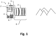
- the observation device according to the invention which is designed in particular as binoculars, for example as binoculars or monoculars, has a fully automatic map-referenced position determination functionality and has a camera (8) with an objective (2) and a camera sensor (3) for recording an image of the terrain surrounding the camera as a camera image. Furthermore, the observation device according to the invention has a data memory for storing program data and a digital terrain model (DTM) (4), the DTM containing at least parts of the surrounding terrain as spatial, digitally processable information.
- DTM digital terrain model
- Said observation device also has a sensor system (5) for the rough initial determination of a spatial position of the observation device, the spatial position having position information and / or orientation information, an evaluation unit (6) with data processing, image data processing and sensor signal evaluation functionality and a display (7) .
- the sensor signal evaluation functionality of the evaluation unit of the observation device according to the invention is configured to carry out a rough initial determination of the spatial position of the observation device by evaluating signals from the sensor system.
- Data processing functionality of the evaluation unit is configured to determine from the stored spatial information of the DTM simulated image positions of the camera (8) in relation to the initially roughly determined spatial position of the observation device, potentially detectable terrain transitions.
- the image data processing functionality of the evaluation unit is configured so that the recorded camera image is automatically checked for the presence of an image of a terrain transition at the determined simulated image positions, with the initially roughly determined spatial position of the observation device and correspondingly the determined simulated image positions of potentially detectable terrain transitions within defined tolerances , in particular based on a previously determined result of the automatic test, can be varied virtually.
- the evaluation unit is configured to repeat the automatic test as part of an optimization, in particular by varying the respective virtual spatial position and the simulated image positions, and to define / determine the spatial position of the observation device as an optimization result based on this.
- At least one of the units data memory, evaluation unit, display can not be located next to or on the observation device but be separated from it and be connected to one another and to the observation device for the purpose of data transmission via a corresponding cable connection or wireless connection.
- the position is determined at a defined point in time at which an image of the surrounding terrain / terrain is recorded by the camera.
- a rough initial determination of the spatial position of the observation device is then carried out by a sensor system, if possible simultaneously with the image acquisition, for example by means of global positioning system (GPS) and digital magnetic compass (DMC) sensors.
- GPS global positioning system
- DMC digital magnetic compass
- the location position / coordinate information of the observation device is determined, for example by means of a GPS sensor.
- a rough initial (potentially highly error-prone) determination of the orientation of the observation device is carried out by one of the methods described above, for example by means of a DMC sensor.
- a DTM i.e. a digital topographical map
- a three-dimensional representation of the terrain area / the terrain surrounding the location is legibly available on the data memory for the process. From this, using the spatial position of the observation device roughly initially determined by the sensor system and the camera calibration, both the mapping of transitions from terrain to the sky (horizon line or only parts of it) and transitions when terrain structures overlap with widely differing distances (e.g. hills before mountains) and the corresponding simulated image positions of all terrain transitions are determined and saved.
- the simulated image positions previously determined for the given spatial position of the observation device of terrain transitions are used to check corresponding image positions of the recorded camera image for the presence of such transitions.
- the spatial position of the observation device is changed / varied virtually in such a way that an optimal correspondence between the correspondingly simulated terrain transitions and the terrain transitions determined in the recorded camera image is achieved.
- the virtual change / variation of the spatial position of the observation device can correspond, for example, to an offset of the position and / or an angle adjustment of one, several or all of the angles that define the orientation of the observation device (e.g. Euler angle: azimuth, elevation and roll angle).
- the size of the offset or the change in angle is based on tolerance values. These defined tolerance values can be predefined, can be set and adapted dynamically during the test, for example based on a result of a previous step of the test, or can be set / determined by a user.
- the spatial position of the observation device found in this way which optimally reproduces all recognizable and determined terrain transitions of the DTM, represents the result of the optimization of the spatial position of the observation device.
- the evaluation unit also takes into account the distance of the respective terrain transition from the camera when automatically checking the recorded camera image for the presence of an image of a terrain transition.
- the simulated image positions determined in each case are displayed superimposed on the recorded camera image on the display (7), in particular with a course of the automatic test being shown visually.
- the observation device has input means which enable a user to abort and / or repeat the automatic test using the input means based on the simulated image positions displayed on the display and superimposed on the camera image. If necessary, further types of influencing the test, for example pausing, navigating back and forth step-by-step between successive steps of the test, etc., can be made available by actuating the input means.
- the input means can also be located on a unit remote from the observation device, e.g. on the data memory, on the evaluation unit or on the display.
- the user can change the automatic test by means of the input means by manually adapting the defined tolerance values in order to redefine / define the spatial position of the observation device.
- the rough initial determination of the spatial position of the observation device by the user using the evaluation unit can be adjusted before the automatic test starts.
- the initially roughly determined spatial position of the observation device is adapted based on the representation of the determined simulated image positions superimposed on the recorded camera image, whereby the initially roughly determined position is manually determined.
- the image information of the recorded camera image required for automatic checking can be processed into a classifier image in which a characteristic value of the probability is calculated for each pixel that the pixel contains the image of a terrain transition.
- the simulated image positions of the terrain transitions calculated in advance for the predetermined spatial position of the observation device are then used to check corresponding image positions in the classifier image for the presence of such transitions.
- the evaluation unit is designed to create a classifier image from the recorded camera image, with the image positions recorded in the classifier image being assigned characteristic values corresponding to the probability of the presence of an image of a terrain transition at said recorded image position, and the corresponding characteristic values are displayed visually as corresponding brightness values and the virtual variation of the spatial position of the observation device and corresponding to the determined simulated image positions of potentially detectable terrain transitions based on a match check of the classifier image with the determined simulated image positions takes place.
- the data memory has the DTM as digitally processable information in the form of point information, said point information being present as x, y, z coordinates, or point connection information or intensity information or color information or as any combination thereof.
- the information that can be processed digitally can have point or area attributes.
- Examples of such representations of the terrain are triangle meshes, polygon meshes, and non-uniform rational B-splines (NURBS).
- the data memory has the DTM stored as digitally processable information in the form of height data in a raster data format.
- the sensor system of the observation device has at least one global positioning system (GPS) sensor and / or at least one digital magnetic compass (DMC) for the initial rough determination of the spatial position of the observation device.
- GPS global positioning system
- DMC digital magnetic compass
- the observation device has a housing that is protected from dust and / or shock and / or splash water.
- the observation device also has a data transceiver for the wireless reception and transmission of DTM data, with received DTM data being stored in the data memory by means of the evaluation unit and DTM data for transmission being retrieved from the data memory by means of the evaluation unit and being made available for transmission.
- the determined simulated image positions are superimposed on a direct view through a telescope of the observation device and this direct view is used to check for the presence of a terrain transition at the calculated image positions.
- this direct view is used to check for the presence of a terrain transition at the calculated image positions.
- simulated images of terrain transitions are superimposed on the direct view through a telescope of the observation device and this direct, superimposed view is used to check for the presence of a terrain transition calculated image positions are used.
- a user can assess the result of the automatic position determination in this way.
- this also has a fastening device and is firmly connected via said fastening device to an object, in particular a helmet, a carrying strap, a tripod, a vehicle, a flight object, after referencing a spatial position of the object with a spatial one Location of the observation device based on the spatial location of the object the fixed / specific spatial position of the observation device is fixed / determined.
- the position determination functionality of the observation device improves a rough (potentially highly error-prone) orientation in all three Euler angles and positions determined with a conventional method described at the beginning and delivers highly accurate spatial position information as a result.
- Fig. 1 shows a sketch of components (1), which provide the position determination functionality of the observation device: A (digital) camera (8) around a part the surroundings / terrain of the location.
- the camera has an image sensor (3) on which a lens (2) is used to image part of the surroundings / terrain, the image information of which is thus accessible in digitally processable form.
- the camera can also be designed, for example, as a thermal imaging camera in order to enable measurements at night and / or in complete darkness.
- the image sensor (3) used should be as high-resolution as possible in order to ensure high measurement accuracy of the local roll angle (rotation of the camera around the main axis of the camera).
- the lens (2) is advantageously designed as a telephoto lens in order to achieve high measurement accuracies in the local azimuth (rotation around the image sensor column direction) and local elevation (rotation around the image sensor row direction).
- the image is usually recorded for short exposure times.
- a sensor system (5) determines the position and a rough initial determination of the orientation is carried out using one of the methods described at the beginning.
- the camera image and the sensor signals are recorded very quickly, with a typical time requirement of well under a second, followed by data processing that can take a few seconds. During the processing time, the system can be moved as required without affecting the measured value. This has advantages, for example, in applications for artillery observers, because the observer after the recording of the camera image and the Sensor signals from the sensor system can immediately return to protected cover.
- the image section of the camera image to be evaluated cannot be selected by the user in a lengthy process or changed several times.
- the position determination works with most of the possible orientations of the camera relative to the terrain.
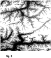
- a DTM of the environment of the observation device / camera is used as part of the processing.
- Fig. 2 shows such a DTM as an example in the format of rasterized elevation data.
- the WGS84 terrain height shown as a grayscale image varies from 200m (black) to over 1000m (white).
- the DTM is a digital version of a topographic map, which contains the elevation of the terrain surface in the form of three-dimensional map information.
- DTM is also used here in summary for other digital descriptions of the surfaces of the terrain, in particular also as a synonym for Digital Surface Model DSM, which also contains height information on buildings and / or vegetation (e.g. forest).
- Data formats that combine both information are also summarized here under the synonym DTM.
- DEM digital elevation model
- TIN triangulated irregular network
- Such data structures are also collectively referred to here with the term DTM.
- DTM triangulated irregular network
- DTM digital representations of surfaces always have a limited spatial resolution, ie the area between the specified data points must / can be interpolated / extrapolated in a suitable manner.
- the execution of the DTM data as rastered heights is only an example in the further description.
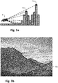
- Fig.3a shows a side view of a DTM as an example in rasterized elevation data.
- the earth's surface is divided into regular longitude intervals and latitude intervals (columns), which are shown here from the side.
- a division of one angular second for longitude and latitude corresponds approximately to a division of the earth's surface into identical rectangles, each with the same horizontal and vertical distances, ie a representation in the form of a grid.
- the height information is stored referenced to a reference system (e.g. WGS84 or EGM96 or EGM2008).
- the simulated position of the observation device within the DTM is indicated by the binoculars (9). From there, at a given azimuth, steps are simulated on the DTM and the DTM terrain height and the distance to the device are simulated Combined angle information (elevation in the local coordinate system of the device).
- the maximum elevation (11a) together with local maxima of the elevation (10a) is determined along the examined azimuth direction.
- the maximum elevation corresponds to a simulated transition from the mapped terrain to the mapped sky, ie a point on the horizon.
- Figure 3b shows the evaluated camera image and in (11b) a point on the horizon line.
- the local maxima (10a) of the elevation correspond to in Figure 3b Transitions (10b) where terrain in the foreground overlaps with terrain in the background (e.g. hill before mountain).
- mapping into the camera image can be simulated, i.e. a series of 2d image coordinates for mapping locations ( simulated image positions) of potentially recognizable terrain transitions.
- mapping locations simulated image positions
- the distance of the underlying terrain transition from the camera from the previous simulation is available for further evaluation.
- the minimum of the two distances involved in the transition is used.
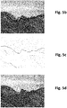
- Fig.5a shows a recorded camera image.
- Figure 5b the simulated image positions drawn in black are superimposed on the camera image. The errors in the spatial position roughly determined at the beginning by the sensor system lead to obvious deviations of the simulated image positions from the terrain transitions actually depicted in the image.
- the recorded camera image is processed.
- the aim is to use the image content to estimate for each pixel how likely a terrain transition is mapped on it.
- Figure 5c shows an example of the result of this processing, the classifier image, in which the brightness values of the pixels were replaced by the probability value (high probabilities are shown in dark here).
- the calculation of the classifier image can also be carried out in a simplified manner, for example by calculating a Canny Edge filter.
- the value of the pixel classification does not have to correspond exactly to the probability - it may be sufficient to use an estimate of a value monotonous to the probability.
- search area the distance to the camera calculated beforehand for the image position is used.
- a larger search area is used for shorter distances to the mapped terrain. For example, the shift of a terrain transition in the image due to forest cover (e.g. maximum considered height of the trees 20m) can be compensated by extending the search from the image position (forest floor) calculated from the DTM to the height of the tree tops.
- the procedure can be improved if, in addition to the DTM, information about the local forest or its height is available.
- the distance-dependent search area can be dispensed with if the Forest cover has already been taken into account in the DTM height information.
- the maximum value of the classification is determined within its search area, i.e. the best match for the terrain transition feature.
- the maximum classification values found in this way are accumulated for all simulated image positions of terrain transitions (for example: all added) and a value is calculated that is used as a target function of a numerical optimization of the camera orientation (previously for the simulation).
- the initially roughly determined spatial position of the observation device is virtually varied in a suitable manner by the optimization algorithm and the simulated image positions of terrain transitions of the DTM are determined again accordingly.
- the determination of the classifier image only needs to be carried out once for the method (for a recorded camera image). Search areas in the classifier image are searched again for the newly calculated / determined image positions, in each case the The maximum value of the classification is determined and these maximum values are accumulated for all image positions. This results in a new objective function value for the varied spatial position of the observation device.
- Fig. 5d shows the result of the optimization.
- the adjustment is fully automatic - no interaction with a user is necessary.
- the user does not have to assign landmarks / reference points to image positions. All simulated image positions (that lie within the image limits) of all potentially recognizable terrain transitions (horizon line: transition between terrain and sky and transitions between overlapping terrain structures at different distances) are always compared with the classifier image - no restriction to individual points (landmarks) is used and no previously known reference points are used either. In this way, it is also possible to determine the position with very simply structured terrain courses in the image content.
- the position determination functionality is robust against a large proportion of incorrect classifications in the classifier image, because on the one hand the correct image positions in the correct spatial position are supported by the comparison with the simulated image positions of the terrain transitions of the DTM and on the other hand, most misclassifications do not participate in the comparison.
- This is a significant advantage compared to methods which try to extract terrain structures exclusively from the image without using the information about the terrain structure, such as in " Camera geolocation from mountain images ". Yi Chen et al., Proceedings of the 18th International Conference on Information Fusion, IEEE, 2013 , disclosed.
- Incorrect classifications in the classifier image occur, for example, when objects unrelated to the terrain are mapped.
- Objects that are not included in the DTM information e.g. trees, vehicles
- can create contrasts in the image that are incorrectly classified as terrain transitions classification false positive
- non-terrain objects in close proximity can cover parts of the terrain and prevent the mapping of terrain transitions (classification false negative).
- Fig. 6 shows such an example.
- the depicted tree (foreign object) in the foreground covers parts of the horizon line and also leads to image contrasts that could be wrongly classified as a terrain transition. Nevertheless, the position determination described here leads fully automatically to the correct solution ( Fig. 6 black line), because the direct comparison of the classifier image with the simulated images of terrain transitions filters out a large part of the misclassifications.
- the camera (known from the simulation of the figure) is used to correct a possible disturbance of the image evaluation due to forest cover.
- the orientation can also be carried out in such a way that preferably more distant terrain transitions are evaluated, because the disturbance of the image evaluation by a forest and the disturbance of the processing by errors in the location position are thereby reduced.
- FIG. 7 is a camera image of such a situation.
- the clouds in the background of the image also cover the horizon line (simulated image positions marked with dashed lines), but not the terrain-terrain transition in the foreground. As all potentially visible terrain transitions are always compared when determining the position, the comparison automatically focuses on more closely situated terrain structures in poor visibility conditions.
- the terrain structure is too simple (e.g. completely flat)
- the elevation angle and roll angle are optimized and thus improved.
- the decision is automatically made to abort with no result of the position determination and an error message.
- the position determination can only be carried out if the terrain and the terrain model match well, i.e. in the case of medium-term changeable terrain (e.g. dunes in the Sahara) a suitable, sufficiently up-to-date DTM must be used.
- medium-term changeable terrain e.g. dunes in the Sahara
- the position determination is used to improve orientation and position (e.g. GPS improvement).
- orientation and position e.g. GPS improvement
- the position and the orientation are varied and improved by the numerical optimization described above.
- the simulated image of the terrain transitions can be superimposed as an overlay on the recorded camera image (compare: 5b and 5d ). This allows the user to judge the result. An inadequately / incorrectly adapted spatial position can then also be corrected manually in the overlay / image comparison.
- the described overlay can also be superimposed on the recorded camera image of a second camera (additional camera).
- additional camera has other parts of the electromagnetic The spectrum (for example thermal imaging camera or night vision device), which takes into account the visual evaluation by the user better than the camera (8) used for determining the position.
- thermal imaging camera or night vision device for example thermal imaging camera or night vision device
- a telescope of the observation device can be designed with a direct view of the surroundings in such a way that indications from a display are perceived as being superimposed on the telescope image.
- the simulated image of the terrain transitions can be superimposed as an overlay on the telescope image (direct view).
- the specific spatial position of the observation device can either be used directly (if a target object has been aimed at) or as an initialization or re-initialization of another position determination method.
- cooperation with an INS system or a DMC measurement (measurement: magnetic declination) or as a starting value for a video tracking system can offer advantages. All three options outlined allow a spatial position to be determined relative to a general target object, regardless of the respective position determination method.
- the initial rough determination of the spatial location can be dispensed with entirely at the beginning.
- the numerical optimization is simply extended to all possible positions and orientations and an optimization method is selected which avoids errors due to local optima.
- the improvement of elevation and roll angle can also be based on a rough inclination measurement (initial values for elevation and roll angle) Surrounding the measured values and improving the azimuth in the entire value range.
- the method can also work entirely without the rough determination of the initial spatial position, in that the initial spatial position is specified by the user. This can be done directly, but also by step-by-step manual adjustment of the orientation or position and comparison of the simulated overlay and the image of the surroundings.
- the system's camera is designed as a thermal imaging camera, the method can also be used at night and / or in absolute darkness.
- Other options for evaluations during the night are offered by versions of the camera as a low-light camera and / or digital residual light amplifier and / or camera in the SWIR range.
Description
Die Erfindung betrifft ein Beobachtungsgerät mit einer Lagebestimmungsfunktionalität zur hochgenauen Bestimmung der räumlichen Lage und somit der Position und Orientierung (z.B. Euler-Winkel: Azimut, Elevations- und Rollwinkel) des Beobachtungsgerätes durch Auswertung eines aufgenommenen Kamerabildes des die Kamera umgebenden Terrains mittels der dreidimensionalen Karteninformation eines digitalen Terrainmodells (DTM).The invention relates to an observation device with a position determination functionality for the highly accurate determination of the spatial location and thus the position and orientation (e.g. Euler angle: azimuth, elevation and roll angle) of the observation device by evaluating a recorded camera image of the terrain surrounding the camera using the three-dimensional map information of a digital terrain model (DTM).
Eine vollautomatische Bestimmung der räumlichen Lage eines Beobachtungsgerätes bietet Vorteile bei der Orientierung auf der Erdoberfläche, zum Beispiel bei der Fortbewegung in unbewohntem Gelände, bei der Steuerung von mit dem Beobachtungsgerät referenzierten autonomen Fahrzeugen (unmanned ground vehicle, UGV) oder unbemannten Flugkörpern (unmanned aerial vehicle, UAV) in geringer Flughöhe.A fully automatic determination of the spatial position of an observation device offers advantages when it comes to orientation on the surface of the earth, for example when moving in uninhabited terrain, when controlling autonomous vehicles (unmanned ground vehicle, UGV) or unmanned aerial vehicles referenced with the observation device , UAV) at low altitude.
Aus dem Stand der Technik bekannte Probleme bei der Bestimmung der räumlichen Lage eines Beobachtungsgerätes oder einer Kamera mittels automatischem Auswerten terrestrischer Bilder der Erdoberfläche, wie beispielsweise Verdeckungen des Terrains durch Bäume/Gebäude/Fahrzeuge, wetterabhängige Farbe und Textur der Terrainflächen, Verwechslung von Wolken mit Terrainstrukturen usw. können zu einer stark fehlerbehafteten und ineffizienten Lagebestimmung führen oder diese gar verunmöglichen.Problems known from the prior art when determining the spatial position of an observation device or a camera by means of automatic evaluation of terrestrial images of the earth's surface, such as obscuration of the terrain by trees / buildings / vehicles, weather-dependent color and texture of the terrain surfaces, confusion of clouds with terrain structures etc. can lead to a highly error-prone and inefficient position determination or even make it impossible.
Eine solche Lagebestimmung eines Beobachtungsgerätes oder einer Kamera, welche auf einer Bestimmung einer Orientierung bzw. Position basiert (kartenreferenzierte Orientierung und Position) wird beispielsweise in der automatisierten Navigation von Fahrzeugen verwendet. Ein anderer Anwendungsbereich ist die Lagebestimmung entfernter Ziele durch geodätische Verfahren, wie Polarpunktaufnahme und Triangulation.Such a determination of the position of an observation device or a camera, which is based on a determination of an orientation or position (map-referenced orientation and position) is for example in the uses automated navigation of vehicles. Another area of application is the determination of the position of distant targets using geodetic methods such as polar point mapping and triangulation.
Bestehende Lagebestimmungen von Beobachtungsgeräten oder Kameras sollen dahingehend verbessert werden, dass diese mit hoher Winkelmessgenauigkeit (z.B. besser als 1 mil) und unter geringem Zeitaufwand im Bereich weniger Sekunden ausgeführt werden können. Zudem soll die entsprechende Lagebestimmung einem definierten Zeitpunkt zugeordnet werden können, wodurch eine Synchronisation im Bereich von Millisekunden ermöglicht wird.Existing position determinations of observation devices or cameras are to be improved in such a way that they can be carried out with high angle measurement accuracy (e.g. better than 1 mil) and with little expenditure of time in the range of a few seconds. In addition, the corresponding position determination should be able to be assigned to a defined point in time, which enables synchronization in the millisecond range.
Nachfolgend werden unterschiedliche aus dem Stand der Technik bekannte Methoden und Mittel zur Lagebestimmung vorgestellt.Various methods and means for determining the position known from the prior art are presented below.
Zur Bestimmung von Elevation und Rollwinkel wird oft eine Messung der Schwerefeldrichtung (Neigungsmessung) beispielsweise mittels Beschleunigungssensoren verwendet.A measurement of the gravitational field direction (inclination measurement), for example by means of acceleration sensors, is often used to determine the elevation and roll angle.
Der Digitale Magnetkompass stellt eine Kombination einer Neigungsmessung mit einer Messung der Richtung des Erdmagnetfelds dar. Zusätzlich zu den Möglichkeiten der Neigungsmessung (siehe oben) wird damit eine Messung des Azimuts erreicht, d.h. es wird die komplette Orientierung (drei Euler-Winkel) gemessen. Dabei wird die Richtung zwingend in Bezug auf die magnetische Nordrichtung bestimmt.The digital magnetic compass is a combination of an inclination measurement with a measurement of the direction of the earth's magnetic field. In addition to the inclination measurement options (see above), azimuth measurement is achieved, ie the complete orientation (three Euler angles) is measured. The direction is determined in relation to the magnetic north.
Die Nordrichtung kann durch einen Kreiselkompass (Gyro) bestimmt werden, indem die Drehung der Erde als Referenz für geographisch Nord verwendet wird. Dafür wird der Kreiselkompass starr mit der Erdoberfläche verbunden und liefert dann nach einigen Minuten die Nordrichtung. Die Messung des Rotationsgeschwindigkeitsvektors der Erde ist nur in starrer Verbindung zur Erdoberfläche möglich.North can be determined by a gyro using the rotation of the earth as a reference for true north. To do this, the gyro compass is rigidly connected to the earth's surface and then provides the north direction after a few minutes. The measurement of the rotation speed vector of the earth is only possible in a rigid connection to the earth's surface.
Die relative Orientierung kann auch mit einer inertialen Messeinheit (inertial measurement unit, IMU) innerhalb eines Systems zur Trägheitsnavigation (inertial navigation system, INS) gemessen werden. Um daraus eine absolute, kartenreferenzierte Orientierung zu erhalten, ist zumindest die Initialisierung mit einem Verfahren zur Messung der kartenreferenzierten Orientierung notwendig. Dafür eignet sich die hier beschriebene Lagebestimmung des Beobachtungsgerätes in idealer Weise, da auch in kompakter Bauweise ein hochgenauer Messwert zu einem sehr genau definierten Zeitpunkt erreichbar ist und durch ständige Messungen der absoluten Orientierung das INS neu referenziert und damit die Fehlerakkumulation (Drift) reduziert wird.The relative orientation can also be measured with an inertial measurement unit (IMU) within an inertial navigation system (INS). In order to obtain an absolute, map-referenced orientation from this, at least initialization with a method for measuring the map-referenced orientation is necessary. The determination of the position of the observation device described here is ideally suited for this, since a highly precise measured value can be achieved at a very precisely defined point in time even in a compact design and the INS is re-referenced through constant measurements of the absolute orientation and thus the accumulation of errors (drift) is reduced.
Durch mehrere voneinander entfernte GPS Messungen kann der Azimut bestimmt werden, indem von der bekannten Standortposition (GPS Messung) auf einen vorher gemessenen früheren Standort zurückgezielt wird. Dies setzt eine Bewegung während der Messung voraus.The azimuth can be determined by several GPS measurements at a distance from one another by aiming back from the known position (GPS measurement) to a previously measured location. This requires movement during the measurement.
Ist die Standortposition bekannt (z.B. GPS Messung), so kann aus Richtungsmessungen (jeweils Azimut und Elevation bezogen auf ein beliebig wählbares lokales Koordinatensystem) zu mindestens zwei Referenzpunkten, deren Position (Koordinaten) im Kartenkoordinatensystem bekannt sind, die komplette kartenreferenzierte Orientierung des Gerätes bestimmt werden (Kartenkoordinatensystem: Azimut bezüglich geographisch Nord, Elevation und Rollwinkel bezüglich Erdschwerefeld). Solche Richtungsmessungen bezogen auf ein lokales Koordinatensystem können durch Anzielen der Referenzpunkte mit einer definierten Achse des Gerätes (z.B. Zielachse eines Theodoliten) oder einfacher durch Abbildung der Referenzpunkte durch eine Kamera und Positionsauswertung im Kamerabild erfolgen (lokales Koordinatensystem = Kamerakoordinatensystem).If the position of the location is known (e.g. GPS measurement), the complete map-referenced orientation of the device can be determined from direction measurements (azimuth and elevation in each case related to any local coordinate system that can be selected) for at least two reference points whose position (coordinates) are known in the map coordinate system (Map coordinate system: azimuth with respect to true north, elevation and roll angle with respect to the earth's gravity field). Such direction measurements based on a local coordinate system can be carried out by aiming at the reference points with a defined axis of the device (e.g. target axis of a theodolite) or more simply by mapping the reference points by a camera and evaluating the position in the camera image (local coordinate system = camera coordinate system).
Die Bestimmung der Orientierung über die zwei Referenzpunkte setzt voraus, dass die beiden Punkte nicht zusammen mit dem Standort auf einer Geraden liegen. Solche Referenzpunkte müssen leicht wiedererkennbar, vorhanden und vom Standort aus für das Verfahren sichtbar sein.The determination of the orientation via the two reference points presupposes that the two points do not lie on a straight line together with the location. Such reference points must be easily recognizable, available and visible from the location for the procedure.
Aus dem Stand der Technik sind auch Lagebestimmungsverfahren unter Verwendung von Richtungsmessungen auf Himmelskörper bekannt.Position determination methods using direction measurements on celestial bodies are also known from the prior art.
Zu einem präzise bekannten (UTC) Zeitpunkt und Datum ist die Position der Himmelsobjekte relativ zur Erde berechenbar. Wird die Standortposition des Beobachters vorgegeben, kann die kartenreferenzierte Richtung zu den Himmelskörpern berechnet werden und diese können als (weit entfernte) Referenzpunkte verwendet werden.The position of the celestial objects relative to the earth can be calculated at a precisely known (UTC) time and date. If the position of the observer is given, the map-referenced direction to the Celestial bodies are calculated and these can be used as (distant) reference points.
Ein digitales Terrainmodel (DTM) ist eine digitale Version einer topographischen Karte, welche den Höhenverlauf der Geländeoberfläche in Form von dreidimensionaler Karteninformation enthält. Der Begriff DTM wird hier zusammenfassend auch für sogenannte Digital Surface Model DSM verwendet, welche auch Höheninformation von Gebäuden und/oder Bewuchs (Wald) enthalten. Schliesslich gibt es auch die Möglichkeit die dreidimensionale Terrainstruktur als triangulated irregular network (TIN) oder mithilfe ähnlicher Geoinformationssystem (GIS) basierten Formate darzustellen. Auch diese Varianten der Terrainrepräsentation sollen hier mit dem gemeinsamen Begriff DTM abgehandelt werden.A digital terrain model (DTM) is a digital version of a topographic map that contains the elevation of the terrain surface in the form of three-dimensional map information. The term DTM is also used here in summary for so-called Digital Surface Model DSM, which also contain height information on buildings and / or vegetation (forest). Finally, there is also the option of displaying the three-dimensional terrain structure as a triangulated irregular network (TIN) or with the help of similar geographic information system (GIS) -based formats. These variants of the terrain representation are also to be dealt with here with the common term DTM.
Die DTM Information kann zur Lagebestimmung im Gelände verwendet werden. Im Folgenden werden entsprechende Dokumente aus der Patentliteratur worin der Nutzen eines DTM's zur Lagebestimmung offenbart ist zusammengefasst.The DTM information can be used to determine the position in the area. Corresponding documents from the patent literature in which the use of a DTM for determining the position is summarized are summarized below.
Die
In
Das System berechnet aus dem eingangs vorliegenden Azimut kombiniert mit Elevation und Standortposition eine Schätzung für die Position des Zielpunkts auf dem DTM. Die Position wird dem Benutzer angezeigt und durch manuelle Eingabe korrigiert. Daraus wird der korrigierte Azimut berechnet.The system calculates an estimate for the position of the target point on the DTM from the azimuth available at the beginning, combined with elevation and location position. The position is displayed to the user and corrected by manual input. The corrected azimuth is calculated from this.
In ähnlicher Weise erreicht
Des Weiteren umfasst der Stand der Technik Verfahren zur Navigation von Raumlandefähren der Raumfahrt, welche auf der räumlichen Lagebestimmung der Raumlandefähre basieren. Beispielsweise werden in
Beispielsweise wird in
Ebenfalls mit der Auswertung der Horizontlinie (Maximal elevation angles, physical skyline, visible horizon) arbeitet
Die Veröffentlichung "
Ein ähnliches Verfahren für urbane Umgebung beschreibt
Die vorliegende Erfindung beschreibt ein Beobachtungsgerät mit einer Lagebestimmungsfunktionalität zur hochgenauen Bestimmung der räumlichen Lage, d.h. der Position und Orientierung, des Beobachtungsgerätes unter Verwendung einer Kamera mit Objektiv, eines digitalen Terrainmodells (DTM) und einer entsprechenden Sensorik in Verbindung mit einer Auswerteeinheit.The present invention describes an observation device with a position determination functionality for the highly precise determination of the spatial position, i.e. the position and orientation, of the observation device using a camera with lens, a digital terrain model (DTM) and a corresponding sensor system in conjunction with an evaluation unit.
Es ist Aufgabe der Erfindung, dass die Bestimmung der kartenreferenzierten Lage des Beobachtungsgerätes in Kurzzeit (wenige Sekunden) vollautomatisch, rein passiv (keine Emission von elektromagnetischer Strahlung), hochpräzise und zu einem definierten Zeitpunkt erfolgt.The object of the invention is that the map-referenced position of the observation device is determined in a short time (a few seconds), fully automatically, purely passively (no emission of electromagnetic radiation), with high precision and at a defined point in time.
Eine weitere Aufgabe der Erfindung besteht darin, dass dabei die Lagebestimmung unbeeinflusst von Störfeldern elektrischer Ströme oder Vibrationen, Bewegungen und Beschleunigungen bleibt.Another object of the invention is that the position determination remains unaffected by interference fields of electrical currents or vibrations, movements and accelerations.
Eine weitere Aufgabe der Erfindung ist es eine Lagebestimmung zu ermöglichen, welche nicht angewiesen ist auf die Sichtbarkeit von vordefinierten Referenzpunkten und unbeeinflusst bleibt von ungünstigen Witterungsverhältnissen wie beispielsweise bedecktem Himmel oder reduzierter Sichtweite.A further object of the invention is to enable a position determination which is not dependent on the visibility of predefined reference points and remains unaffected by unfavorable weather conditions such as, for example, an overcast sky or reduced visibility.
Eine weitere Aufgabe der Erfindung besteht darin, dass die kartenreferenzierte Lagebestimmung des Beobachtungsgerätes möglichst unabhängig vom Umfeld (auch kaum oder gar nicht besiedelt) erfolgen kann und auch für eine terrestrische Lagebestimmung (beispielsweise UAV in geringer Flughöhe) geeignet ist.A further object of the invention is that the map-referenced position determination of the observation device can be carried out as independently as possible of the surroundings (also hardly or not at all populated) and also for a terrestrial one Position determination (for example UAV at low altitude) is suitable.
Diese Aufgaben werden durch die Verwirklichung der kennzeichnenden Merkmale des unabhängigen Anspruchs gelöst. Merkmale, die die Erfindung in alternativer oder vorteilhafter Weise weiterbilden, sind den abhängigen Patentansprüchen zu entnehmen.These objects are achieved by implementing the characterizing features of the independent claim. Features that develop the invention in an alternative or advantageous manner can be found in the dependent claims.
Das erfindungsgemässe Beobachtungsgerät, welches insbesondere als Fernglas ausgebildet ist, beispielsweise als Binokular oder Monokular weist eine vollautomatische kartenreferenzierte Lagebestimmungsfunktionalität auf und hat eine Kamera (8) mit einem Objektiv (2) und einem Kamerasensor (3) zur Aufnahme eines Bildes eines die Kamera umgebenden Geländes als Kamerabild. Des Weiteren weist das erfindungsgemässe Beobachtungsgerät einen Datenspeicher zur Speicherung von Programmdaten und einem digitalen Terrainmodell (DTM) (4) auf, wobei das DTM zumindest Teile des umgebenden Geländes als räumliche, digital prozessierbare Information enthält. Besagtes Beobachtungsgerät hat ausserdem eine Sensorik (5) zur groben initialen Bestimmung einer räumlichen Lage des Beobachtungsgerätes wobei die räumliche Lage eine Positionsinformation und/oder eine Orientierungsinformation aufweist, eine Auswerteeinheit (6) mit Datenverarbeitungs-, Bilddatenverabeitungs- und Sensorsignalauswertungsfunktionalität und ein Display (7). Dabei ist die Sensorsignalauswertungsfunktionalität der Auswerteeinheit des erfindungsgemässen Beobachtungsgerätes dazu konfiguriert, um mittels Auswertung von Signalen der Sensorik eine grobe initiale Bestimmung der räumlichen Lage des Beobachtungsgerätes durchzuführen. DieThe observation device according to the invention, which is designed in particular as binoculars, for example as binoculars or monoculars, has a fully automatic map-referenced position determination functionality and has a camera (8) with an objective (2) and a camera sensor (3) for recording an image of the terrain surrounding the camera as a camera image. Furthermore, the observation device according to the invention has a data memory for storing program data and a digital terrain model (DTM) (4), the DTM containing at least parts of the surrounding terrain as spatial, digitally processable information. Said observation device also has a sensor system (5) for the rough initial determination of a spatial position of the observation device, the spatial position having position information and / or orientation information, an evaluation unit (6) with data processing, image data processing and sensor signal evaluation functionality and a display (7) . The sensor signal evaluation functionality of the evaluation unit of the observation device according to the invention is configured to carry out a rough initial determination of the spatial position of the observation device by evaluating signals from the sensor system. The
Datenverarbeitungsfunktionalität der Auswerteeinheit ist dazu konfiguriert, um aus der gespeicherten räumlichen Information des DTM simulierte Bildpositionen von von der Kamera (8), in Bezug auf die initial grob bestimmte räumliche Lage des Beobachtungsgerätes, potenziell erfassbaren Terrainübergängen zu ermitteln. Die Bilddatenverarbeitungsfunktionalität der Auswerteeinheit ist dazu konfiguriert, dass an den ermittelten simulierten Bildpositionen das aufgenommene Kamerabild auf ein Vorhandensein einer Abbildung eines Terrainübergangs automatisch geprüft wird, wobei die initial grob bestimmte räumliche Lage des Beobachtungsgerätes und entsprechend die ermittelten simulierten Bildpositionen von potenziell erfassbaren Terrainübergängen innerhalb definierter Toleranzen, insbesondere basierend auf einem vorgängig ermittelten Ergebnis der automatischen Prüfung, virtuell variiert werden. Des Weiteren ist die Auswerteeinheit dazu konfiguriert die automatische Prüfung im Rahmen einer Optimierung, insbesondere unter Variierung der jeweiligen virtuellen räumlichen Lage und der simulierten Bildpositionen, zu wiederholen und als Optimierungsergebnis basierend darauf die räumliche Lage des Beobachtungsgerätes festzulegen/ zu bestimmen.Data processing functionality of the evaluation unit is configured to determine from the stored spatial information of the DTM simulated image positions of the camera (8) in relation to the initially roughly determined spatial position of the observation device, potentially detectable terrain transitions. The image data processing functionality of the evaluation unit is configured so that the recorded camera image is automatically checked for the presence of an image of a terrain transition at the determined simulated image positions, with the initially roughly determined spatial position of the observation device and correspondingly the determined simulated image positions of potentially detectable terrain transitions within defined tolerances , in particular based on a previously determined result of the automatic test, can be varied virtually. Furthermore, the evaluation unit is configured to repeat the automatic test as part of an optimization, in particular by varying the respective virtual spatial position and the simulated image positions, and to define / determine the spatial position of the observation device as an optimization result based on this.
In einer möglichen alternativen Ausführungsform kann sich mindestens eine der Einheiten Datenspeicher, Auswerteeinheit, Display nicht beim oder am Beobachtungsgerät befinden sondern davon abgesetzt sein und über eine entsprechende Kabelverbindung oder kabellose Verbindung untereinander und mit dem Beobachtungsgerät zwecks Datenübermittlung verbunden sein. Dabei befindet sich am Beobachtungsgerät selber lediglich eine Datenkommunikationsschnittstelle. Diese findet sich dann entsprechend auch an den abgesetzten Einheiten und dient dem Senden und Empfangen entsprechender Daten.In a possible alternative embodiment, at least one of the units data memory, evaluation unit, display can not be located next to or on the observation device but be separated from it and be connected to one another and to the observation device for the purpose of data transmission via a corresponding cable connection or wireless connection. There is only one data communication interface on the observation device itself. This is then found accordingly also on the remote units and is used to send and receive the corresponding data.
Die Lagebestimmung erfolgt in jedem Fall zu einem definierten Zeitpunkt an dem ein Bild des umgebenden Terrains/Geländes von der Kamera aufgenommen wird. Möglichst gleichzeitig zur Bildaufnahme wird dann durch eine Sensorik eine grobe initiale Bestimmung der räumlichen Lage des Beobachtungsgerätes durchgeführt, beispielsweise mittels global positioning system (GPS) und digital magnetic compass (DMC) Sensoren. Einerseits wird dabei die Standortposition/Koordinateninformation des Beobachtungsgerätes ermittelt, beispielsweise mittels GPS Sensor. Andererseits wird eine grobe initiale (potentiell stark fehlerbehaftete) Bestimmung der Orientierung des Beobachtungsgerätes durch eines der eingangs beschriebenen Verfahren durchgeführt, beispielsweise mittels DMC Sensor.In each case, the position is determined at a defined point in time at which an image of the surrounding terrain / terrain is recorded by the camera. A rough initial determination of the spatial position of the observation device is then carried out by a sensor system, if possible simultaneously with the image acquisition, for example by means of global positioning system (GPS) and digital magnetic compass (DMC) sensors. On the one hand, the location position / coordinate information of the observation device is determined, for example by means of a GPS sensor. On the other hand, a rough initial (potentially highly error-prone) determination of the orientation of the observation device is carried out by one of the methods described above, for example by means of a DMC sensor.
Ein DTM, also eine digitale topographische Karte, mit dreidimensionaler Repräsentation der Terrainfläche/des Geländes der Umgebung des Standortes ist für das Verfahren lesbar auf dem Datenspeicher vorhanden. Hieraus wird unter Verwendung der durch die Sensorik grob initial bestimmten räumlichen Lage des Beobachtungsgerätes und der Kamerakalibrierung sowohl die Abbildung von Übergängen von Terrain zum Himmel (Horizontlinie oder auch nur Teile davon) als auch von Übergängen bei Überlappung von Terrainstrukturen mit stark unterschiedlichem Abstand (z.B. Hügel vor Bergen) berechnet und die entsprechenden simulierten Bildpositionen aller Terrainübergänge ermittelt und gespeichert.A DTM, i.e. a digital topographical map, with a three-dimensional representation of the terrain area / the terrain surrounding the location is legibly available on the data memory for the process. From this, using the spatial position of the observation device roughly initially determined by the sensor system and the camera calibration, both the mapping of transitions from terrain to the sky (horizon line or only parts of it) and transitions when terrain structures overlap with widely differing distances (e.g. hills before mountains) and the corresponding simulated image positions of all terrain transitions are determined and saved.
Die vorgängig zur vorgegebenen räumlichen Lage des Beobachtungsgerätes ermittelten, simulierten Bildpositionen von Terrainübergängen werden verwendet, um entsprechende Bildpositionen des aufgenommenen Kamerabildes auf das Vorhandensein solcher Übergänge zu prüfen.The simulated image positions previously determined for the given spatial position of the observation device of terrain transitions are used to check corresponding image positions of the recorded camera image for the presence of such transitions.
Im Rahmen einer numerischen Optimierung wird die räumliche Lage des Beobachtungsgerätes virtuell so verändert/variiert, dass eine optimale Übereinstimmung zwischen entsprechend simulierten Terrainübergängen und im aufgenommenen Kamerabild ermittelten Terrainübergängen erreicht wird. Die virtuelle Veränderung/Variation der räumlichen Lage des Beobachtungsgerätes kann beispielsweise einem Versatz der Position und/oder einer Winkelanpassung eines, mehrerer oder aller Winkel, welche die Orientierung des Beobachtungsgerätes definieren (z.B. Euler-Winkel: Azimut, Elevations- und Rollwinkel), entsprechen. Dabei wird die Grösse beispielsweise des Versatzes oder der Winkelveränderung basierend auf Toleranzwerten erfolgen. Diese definierten Toleranzwerte können vordefiniert sein, dynamisch während der Prüfung, beispielsweise basierend auf einem Ergebnis eines vorgängigen Schrittes der Prüfung, festgelegt und angepasst werden, oder von einem Benutzer festgelegt/bestimmt sein.As part of a numerical optimization, the spatial position of the observation device is changed / varied virtually in such a way that an optimal correspondence between the correspondingly simulated terrain transitions and the terrain transitions determined in the recorded camera image is achieved. The virtual change / variation of the spatial position of the observation device can correspond, for example, to an offset of the position and / or an angle adjustment of one, several or all of the angles that define the orientation of the observation device (e.g. Euler angle: azimuth, elevation and roll angle). The size of the offset or the change in angle, for example, is based on tolerance values. These defined tolerance values can be predefined, can be set and adapted dynamically during the test, for example based on a result of a previous step of the test, or can be set / determined by a user.
Die so gefundene räumliche Lage des Beobachtungsgerätes, die sämtliche erkennbaren und ermittelten Terrainübergänge des DTM optimal reproduziert, stellt das Ergebnis der Optimierung der räumlichen Lage des Beobachtungsgerätes dar.The spatial position of the observation device found in this way, which optimally reproduces all recognizable and determined terrain transitions of the DTM, represents the result of the optimization of the spatial position of the observation device.
In einer weiteren Ausführungsform berücksichtigt die Auswerteeinheit bei der automatischen Prüfung des aufgenommenen Kamerabildes auf das Vorhandensein einer Abbildung eines Terrainübergangs den Abstand des jeweiligen Terrainübergangs zur Kamera mit.In a further embodiment, the evaluation unit also takes into account the distance of the respective terrain transition from the camera when automatically checking the recorded camera image for the presence of an image of a terrain transition.
Gemäss einer weiteren Ausführungsform des Beobachtungsgerätes werden die jeweils ermittelten simulierten Bildpositionen dem aufgenommenen Kamerabild überlagert auf dem Display (7) angezeigt, insbesondere wobei ein Verlauf der automatischen Prüfung visuell dargestellt wird.According to a further embodiment of the observation device, the simulated image positions determined in each case are displayed superimposed on the recorded camera image on the display (7), in particular with a course of the automatic test being shown visually.
In einer vorteilhaften Ausführungsform weist das Beobachtungsgerät Eingabemittel auf, welche es einem Benutzer ermöglichen basierend auf den auf dem Display angezeigten, dem Kamerabild überlagerten simulierten Bildpositionen die automatische Prüfung mittels der Eingabemittel abbrechen, und/oder wiederholen zu können. Gegebenenfalls können weitere Arten der Einflussnahme auf die Prüfung, beispielsweise pausieren, schrittweises vor und zurück navigieren zwischen aufeinanderfolgenden Schritten der Prüfung usw. mittels Betätigung der Eingabemittel zur Verfügung gestellt werden.In an advantageous embodiment, the observation device has input means which enable a user to abort and / or repeat the automatic test using the input means based on the simulated image positions displayed on the display and superimposed on the camera image. If necessary, further types of influencing the test, for example pausing, navigating back and forth step-by-step between successive steps of the test, etc., can be made available by actuating the input means.
In einer alternativen Ausführungsform können sich die Eingabemittel auch an einer vom Beobachtungsgerät abgesetzten Einheit, z.B. am Datenspeicher, an der Auswerteeinheit oder am Display befinden.In an alternative embodiment, the input means can also be located on a unit remote from the observation device, e.g. on the data memory, on the evaluation unit or on the display.
In einer weiteren Ausführungsform des Beobachtungsgerätes kann der Benutzer die automatische Prüfung mittels der Eingabemittel durch ein manuelles Anpassen der definierten Toleranzwerte verändern, um die räumliche Lage des Beobachtungsgerätes neu zu bestimmen/festzulegen.In a further embodiment of the observation device, the user can change the automatic test by means of the input means by manually adapting the defined tolerance values in order to redefine / define the spatial position of the observation device.
Gemäss einer vorteilhaften Ausführungsform kann die mittels der Auswerteeinheit erfolgende grobe initiale Bestimmung der räumlichen Lage des Beobachtungsgerätes durch den Benutzer mittels der Eingabemittel angepasst werden, bevor die automatische Prüfung startet. Beispielsweise erfolgt die Anpassung der initial grob bestimmten räumlichen Lage des Beobachtungsgerätes basierend auf der dem aufgenommenen Kamerabild überlagerten Darstellung der ermittelten simulierten Bildpositionen wodurch die initial grob bestimmte Lage manuell bestimmt wird.According to an advantageous embodiment, the rough initial determination of the spatial position of the observation device by the user using the evaluation unit can be adjusted before the automatic test starts. For example, the initially roughly determined spatial position of the observation device is adapted based on the representation of the determined simulated image positions superimposed on the recorded camera image, whereby the initially roughly determined position is manually determined.
Die zur automatischen Prüfung notwendige Bildinformation des aufgenommenen Kamerabildes kann zu einem Klassifikatorbild verarbeitet werden, bei dem für jeden Pixel ein Kennwert der Wahrscheinlichkeit berechnet wird, dass der Pixel die Abbildung eines Terrainübergangs enthält. Die vorgängig zur vorgegebenen räumlichen Lage des Beobachtungsgerätes berechneten simulierten Bildpositionen der Terrainübergänge werden dann verwendet, um entsprechende Bildpositionen im Klassifikatorbild auf das Vorhandensein solcher Übergänge zu prüfen.The image information of the recorded camera image required for automatic checking can be processed into a classifier image in which a characteristic value of the probability is calculated for each pixel that the pixel contains the image of a terrain transition. The simulated image positions of the terrain transitions calculated in advance for the predetermined spatial position of the observation device are then used to check corresponding image positions in the classifier image for the presence of such transitions.
Daher ist in einer weiteren Ausführungsform des Beobachtungsgerätes die Auswerteeinheit dazu ausgelegt, um aus dem aufgenommenen Kamerabild ein Klassifikatorbild zu erstellen, wobei im Klassifikatorbild aufgenommenen Bildpositionen Kennwerte, entsprechend der Wahrscheinlichkeit des Vorhandenseins einer Abbildung eines Terrainübergangs an besagter aufgenommener Bildposition, zugeordnet werden und die entsprechenden Kennwerte visuell als entsprechende Helligkeitswerte dargestellt werden und die virtuelle Variation der räumlichen Lage des Beobachtungsgerätes und entsprechend der ermittelten simulierten Bildpositionen von potenziell erfassbaren Terrainübergängen basierend auf einer Übereinstimmungsprüfung des Klassifikatorbildes mit den ermittelten simulierten Bildpositionen erfolgt.Therefore, in a further embodiment of the observation device, the evaluation unit is designed to create a classifier image from the recorded camera image, with the image positions recorded in the classifier image being assigned characteristic values corresponding to the probability of the presence of an image of a terrain transition at said recorded image position, and the corresponding characteristic values are displayed visually as corresponding brightness values and the virtual variation of the spatial position of the observation device and corresponding to the determined simulated image positions of potentially detectable terrain transitions based on a match check of the classifier image with the determined simulated image positions takes place.
Gemäss einer weiteren Ausführungsform weist der Datenspeicher das DTM als digital prozessierbare Information in Form von Punktinformationen auf, wobei besagte Punktinformationen als x,y,z Koordinaten, oder Punktverbindungsinformationen oder Intensitätsinformationen oder Farbinformationen oder als beliebige Kombination davon vorliegen.According to a further embodiment, the data memory has the DTM as digitally processable information in the form of point information, said point information being present as x, y, z coordinates, or point connection information or intensity information or color information or as any combination thereof.
Des Weiteren kann die digital prozessierbare Information-Punkt- bzw. Flächenattribute aufweisen. Beispiele für solche Repräsentationen des Terrains sind Dreiecksnetze, Polygonnetze und nicht-uniforme rationale B-Splines (NURBS).Furthermore, the information that can be processed digitally can have point or area attributes. Examples of such representations of the terrain are triangle meshes, polygon meshes, and non-uniform rational B-splines (NURBS).
Gemäss einer weiteren Ausführungsform weist der Datenspeicher das DTM als digital prozessierbare Information in Form von Höhendaten in einem Rasterdatenformat gespeichert auf.According to a further embodiment, the data memory has the DTM stored as digitally processable information in the form of height data in a raster data format.
In einer weiteren Ausführungsform weist die Sensorik des Beobachtungsgerätes mindestens einen Global Positioning System (GPS) Sensor und/oder mindestens einen digitalen magnetischen Kompass (DMC) zur initialen groben Bestimmung der räumlichen Lage des Beobachtungsgerätes auf.In a further embodiment, the sensor system of the observation device has at least one global positioning system (GPS) sensor and / or at least one digital magnetic compass (DMC) for the initial rough determination of the spatial position of the observation device.
In einer vorteilhaften Ausführungsform des Beobachtungsgerätes hat dieses ein staub- und/oder stoss- und/oder spritzwassergeschütztes Gehäuse.In an advantageous embodiment of the observation device, it has a housing that is protected from dust and / or shock and / or splash water.
In einer weiteren vorteilhaften Ausführungsform hat das Beobachtungsgerät ausserdem einen Datentransceiver zum drahtlosen Empfangen und Senden von DTM Daten, wobei empfangene DTM Daten mittels der Auswerteeinheit im Datenspeicher gespeichert werden und DTM Daten zum Senden mittels der Auswerteeinheit vom Datenspeicher abgerufen und zum Senden bereitgestellt werden.In a further advantageous embodiment, the observation device also has a data transceiver for the wireless reception and transmission of DTM data, with received DTM data being stored in the data memory by means of the evaluation unit and DTM data for transmission being retrieved from the data memory by means of the evaluation unit and being made available for transmission.
Gemäss einer alternativen Ausführungsform des Beobachtungsgerätes werden die ermittelten simulierten Bildpositionen einer direkten Sicht durch ein Fernrohr des Beobachtungsgerätes überlagert und es wird diese direkte Sicht benutzt zur Prüfung auf das Vorhandensein eines Terrainübergangs an den berechneten Bildpositionen. Dabei wird beispielsweise die Variation/Veränderung der räumlichen Lage des Beobachtungsgerätes nicht virtuell erfolgen, sondern durch ein entsprechendes reales Versetzen bzw. Verschwenken des Beobachtungsgerätes.According to an alternative embodiment of the observation device, the determined simulated image positions are superimposed on a direct view through a telescope of the observation device and this direct view is used to check for the presence of a terrain transition at the calculated image positions. In this case, for example, the variation / change in the spatial position of the observation device will not take place virtually, but rather through a corresponding real displacement or pivoting of the observation device.
In einer weiteren, alternativen Ausführungsform des Beobachtungsgerätes werden simulierte Abbildungen von Terrainübergängen, insbesondere basierend auf einem ermittelten Klassifikatorbild oder den berechneten Bildpositionen, der direkten Sicht durch ein Fernrohr des Beobachtungsgerätes überlagert und diese direkte, überlagerte Sicht wird zur Prüfung auf das Vorhandensein eines Terrainübergangs an den berechneten Bildpositionen benutzt.In a further, alternative embodiment of the observation device, simulated images of terrain transitions, in particular based on a determined classifier image or the calculated image positions, are superimposed on the direct view through a telescope of the observation device and this direct, superimposed view is used to check for the presence of a terrain transition calculated image positions are used.
In einem vollautomatischen Verfahren, basierend auf der Auswertung eines Kamerabildes kann auf diese Weise ein Benutzer, das Ergebnis der automatischen Lagebestimmung beurteilen.In a fully automatic method, based on the evaluation of a camera image, a user can assess the result of the automatic position determination in this way.
In einer weiteren vorteilhaften Ausführungsform des Beobachtungsgerätes weist dieses ausserdem eine Befestigungsvorrichtung auf und ist über besagte Befestigungsvorrichtung fest mit einem Objekt insbesondere einem Helm, einem Tragegurt, einem Stativ, einem Fahrzeug, einem Flugobjekt verbunden wobei nach einer Referenzierung einer räumlichen Lage des Objekts mit einer räumlichen Lage des Beobachtungsgerätes die räumliche Lage des Objekts basierend auf der festgelegten/bestimmten räumlichen Lage des Beobachtungsgerätes festgelegt/bestimmt wird.In a further advantageous embodiment of the observation device, this also has a fastening device and is firmly connected via said fastening device to an object, in particular a helmet, a carrying strap, a tripod, a vehicle, a flight object, after referencing a spatial position of the object with a spatial one Location of the observation device based on the spatial location of the object the fixed / specific spatial position of the observation device is fixed / determined.
Das erfindungsgemässe Beobachtungsgerät mit Lagebestimmungsfunktionalität wird nachfolgend anhand von in den Zeichnungen schematisch dargestellten konkreten Ausführungsbeispielen rein beispielhaft näher beschrieben, wobei auch auf weitere Vorteile der Erfindung eingegangen wird. Im Einzelnen zeigen:
-
Fig.1 beispielhaft die Komponenten, welche die Lagebestimmungsfunktionalität des Beobachtungsgerätes bereitstellen(1): eine Kamera(8), bestehend aus
einem Objektiv (2) und einem Bildsensor (3);
ein Datenspeicher zur Speicherung von Programmdaten und DTM (4); eine Sensorik (5); eine Auswerteeinheit (6) sowie ein Display (7), -
Fig.2 ein DTM hier als Beispiel im Format gerasterter Höhendaten, -
Fig.3a eine Skizze der Berechnung simulierter Bildpositionen von Terrainübergängen, -
Fig.3b ein Beispiel von simulierten Bildpositionen (schwarze Linien), die dem Kamerabild überlagert wurden, -
Fig.4 eine Skizze der Berechnung des Einflusses der Erdkrümmung und der atmosphärischen Refraktion auf die Berechnung simulierter Bildpositionen, -
Fig.5a beispielhaft das von der Kamera aufgenommene Bild (Kamerabild) für die Auswertung, -
Fig.5b die basierend auf der initial groben Lagemessung und dem DTM simulierten Bildpositionen von Terrainübergängen, -
Fig.5c ein aus dem Kamerabild berechnetes/ermitteltes Klassifikatorbild, -
Fig.5d das Ergebnis einer Optimierung, welche zu einer präziseren Lagebestimmung führt ausgehend von aus dem DTM simulierten Bildpositionen von Terrainübergängen, -
Fig.6 ein Beispiel für im Kamerabild abgebildete terrainfremde Strukturen (Bäume) und das trotzdem korrekte Ergebnis der Optimierung, -
Fig.7 das Ergebnis einer Lagebestimmung ausgehend von einem Kamerabild mit wetterbedingter, reduzierter Sichtweite.
-
Fig. 1 for example, the components that provide the position determination functionality of the observation device (1): a camera (8), consisting of
an objective (2) and an image sensor (3);
a data memory for storing program data and DTM (4); a sensor system (5); an evaluation unit (6) and a display (7), -
Fig. 2 a DTM here as an example in the format of rasterized elevation data, -
Fig.3a a sketch of the calculation of simulated image positions of terrain transitions, -
Fig.3b an example of simulated image positions (black lines) that have been superimposed on the camera image, -
Fig. 4 a sketch of the calculation of the influence of the earth's curvature and atmospheric refraction on the calculation of simulated image positions, -
Fig.5a an example of the image recorded by the camera (camera image) for the evaluation, -
Fig.5b the image positions of terrain transitions simulated based on the initially rough position measurement and the DTM, -
Fig.5c a classifier image calculated / determined from the camera image, -
Fig.5d the result of an optimization which leads to a more precise position determination based on the image positions of terrain transitions simulated from the DTM, -
Fig. 6 an example of non-terrain structures (trees) shown in the camera image and the nevertheless correct result of the optimization, -
Fig. 7 the result of a position determination based on a camera image with weather-related, reduced visibility.
Es versteht sich, dass diese dargestellten Figuren nur mögliche Ausführungsbeispiele schematisch darstellen. Die verschiedenen Ansätze können ebenso miteinander sowie mit Verfahren des Stands der Technik kombiniert werden.It goes without saying that these figures shown only represent possible exemplary embodiments schematically. The different approaches can also be combined with one another as well as with prior art methods.
Die Lagebestimmungsfunktionalität des Beobachtungsgerätes verbessert eine mit einem eingangs beschriebenen herkömmlichen Verfahren bestimmte grobe (potentiell stark fehlerbehaftete) Orientierung in allen drei Euler-Winkeln und Position und liefert als Ergebnis eine hochgenaue räumliche Lageinformation.The position determination functionality of the observation device improves a rough (potentially highly error-prone) orientation in all three Euler angles and positions determined with a conventional method described at the beginning and delivers highly accurate spatial position information as a result.
Vorteilhaft wird das Objektiv (2) als Teleobjektiv ausgeführt, um hohe Messgenauigkeiten beim lokalen Azimut (Rotation um die Bildsensor-Spaltenrichtung) und lokaler Elevation (Rotation um die Bildsensor-Zeilenrichtung) zu erreichen.The lens (2) is advantageously designed as a telephoto lens in order to achieve high measurement accuracies in the local azimuth (rotation around the image sensor column direction) and local elevation (rotation around the image sensor row direction).
Die Bildaufnahme erfolgt in der Regel für kurze Belichtungszeiten. Möglichst gleichzeitig dazu wird von einer Sensorik (5) die Standortposition bestimmt und eine grobe initiale Bestimmung der Orientierung mittels einem der eingangs beschriebenen Verfahren durchgeführt.The image is usually recorded for short exposure times. At the same time as possible, a sensor system (5) determines the position and a rough initial determination of the orientation is carried out using one of the methods described at the beginning.
Die Aufnahme des Kamerabildes und der Sensorsignale (Standortposition und Orientierung) erfolgt sehr schnell, mit einem typischen Zeitbedarf von deutlich unter einer Sekunde, danach folgt eine Datenverarbeitung die einige Sekunden dauern kann. Während der Verarbeitungszeit kann das System beliebig bewegt werden, ohne dass der Messwert beeinflusst wird. Dies hat zum Beispiel Vorteile bei Anwendungen für Artilleriebeobachter, weil sich der Beobachter nach der Aufnahme des Kamerabildes und der Sensorsignale der Sensorik sofort wieder in geschützte Deckung begeben kann.The camera image and the sensor signals (position and orientation) are recorded very quickly, with a typical time requirement of well under a second, followed by data processing that can take a few seconds. During the processing time, the system can be moved as required without affecting the measured value. This has advantages, for example, in applications for artillery observers, because the observer after the recording of the camera image and the Sensor signals from the sensor system can immediately return to protected cover.
Wie man an diesem Anwendungsbeispiel leicht sieht, kann der auszuwertende Bildausschnitt des Kamerabildes nicht in einem langwierigen Prozess vom Benutzer ausgewählt oder mehrfach verändert werden.As you can easily see from this application example, the image section of the camera image to be evaluated cannot be selected by the user in a lengthy process or changed several times.
Idealerweise funktioniert die Lagebestimmung mit den meisten der möglichen Orientierungen der Kamera relativ zum Gelände.Ideally, the position determination works with most of the possible orientations of the camera relative to the terrain.
Im Rahmen der Verarbeitung wird ein DTM der Umgebung des Beobachtungsgerätes/der Kamera verwendet.
Der Begriff DTM wird hier zusammenfassend auch für andere digitale Beschreibungen der Oberflächen des Terrains, insbesondere auch als Synonym für Digital Surface Model DSM verwendet, welches auch Höheninformation von Gebäuden und/oder Bewuchs (z.B. Wald) enthält. Auch Datenformate, welche beide Informationen kombinieren (oft als Digitales Elevationsmodell oder DEM bezeichnet), werden hier unter dem Synonym DTM zusammengefasst. Zudem existiert die Möglichkeit die dreidimensionale Terrainstruktur als triangulated irregular network (TIN) oder mithilfe ähnlicher GIS Formate darzustellen. Auch solche Datenstrukturen werden hier zusammenfassend mit dem Begriff DTM bezeichnet. Insbesondere gibt es auch die Möglichkeit, statt natürlicher Terrainstrukturen, zusätzlich oder ausschliesslich Oberflächenbeschreibungen künstlicher Strukturen wie Gebäuden, Brücken und Strassen zu verwenden. Auch solche typischerweise als GIS Datenformat gespeicherte Beschreibungen der umliegenden Oberflächen können für das Verfahren verwendet und sollen hier ebenfalls mit dem Begriff DTM bezeichnet werden. Digitale Repräsentationen von Oberflächen haben stets eine limitierte Ortsauflösung, d.h. die Fläche zwischen den vorgegebenen Datenpunkten muss/kann in geeigneter Weise interpoliert/extrapoliert werden. Die Ausführung der DTM Daten als gerasterte Höhen ist in der weiteren Beschreibung nur beispielhaft.The term DTM is also used here in summary for other digital descriptions of the surfaces of the terrain, in particular also as a synonym for Digital Surface Model DSM, which also contains height information on buildings and / or vegetation (e.g. forest). Data formats that combine both information (often referred to as digital elevation model or DEM) are also summarized here under the synonym DTM. There is also the option of displaying the three-dimensional terrain structure as a triangulated irregular network (TIN) or using similar GIS formats. Such data structures are also collectively referred to here with the term DTM. In particular, there is also the possibility instead of natural terrain structures, additionally or exclusively to use surface descriptions of artificial structures such as buildings, bridges and streets. Such descriptions of the surrounding surfaces, typically stored as GIS data format, can also be used for the method and should also be referred to here with the term DTM. Digital representations of surfaces always have a limited spatial resolution, ie the area between the specified data points must / can be interpolated / extrapolated in a suitable manner. The execution of the DTM data as rastered heights is only an example in the further description.
Die simulierte Standortposition des Beobachtungsgerätes innerhalb des DTM wird durch das Fernglas (9) gekennzeichnet. Von dort aus werden, zu einem vorgegebenen Azimut, Schritte auf dem DTM simuliert und jeweils die DTM-Geländehöhe und der Abstand zum Gerät zu einer Winkelinformation kombiniert (Elevation im lokalen Koordinatensystem des Gerätes). Entlang der untersuchten Azimut Richtung wird die maximale Elevation (11a) zusammen mit lokalen Maxima der Elevation (10a) bestimmt. Die maximale Elevation entspricht einem simulierten Übergang von abgebildetem Terrain zu abgebildetem Himmel, d.h. einem Horizontpunkt.
Eine entsprechende Simulation wird für viele der Azimut Richtungen des Kameragesichtsfelds durchgeführt. Die (vielen) Punkte sind in
Die Berechnung wurde hier vereinfacht dargestellt. Wie in
Verwendet man die eingangs grob gemessene räumliche Lage des Beobachtungsgerätes so kann aus den vorher aus dem DTM berechneten Richtungen zu im Bild potenziell sichtbaren Terrainübergängen (unter Verwendung einer Kamerakalibrierung) deren Abbildung ins Kamerabild simuliert werden, d.h. man erhält eine Reihe von 2d Bildkoordinaten für Abbildungsorte (simulierte Bildpositionen) potenziell erkennbarer Terrainübergänge. Zu jeder dieser Bildpositionen ist der Abstand des zugrundeliegenden Terrainübergangs von der Kamera aus der vorher erfolgten Simulation (Elevation Berechnung) für die weitere Auswertung verfügbar. Für simulierte Übergänge aus Überlappung von Terrainstrukturen unterschiedlichen Abstands wird dafür der minimale der beiden am Übergang beteiligten Abstände verwendet.If the initially roughly measured spatial position of the observation device is used, then from the directions calculated beforehand from the DTM to terrain transitions that are potentially visible in the image (using a camera calibration) their mapping into the camera image can be simulated, i.e. a series of 2d image coordinates for mapping locations ( simulated image positions) of potentially recognizable terrain transitions. For each of these image positions, the distance of the underlying terrain transition from the camera from the previous simulation (elevation calculation) is available for further evaluation. For simulated transitions from overlapping terrain structures with different distances, the minimum of the two distances involved in the transition is used.
Das aufgenommene Kamerabild wird prozessiert. Ziel ist es, anhand des Bildinhaltes für jeden Pixel abzuschätzen, wie wahrscheinlich darauf ein Terrainübergang abgebildet ist.
Die Berechnung des Klassifikatorbildes kann auch vereinfacht erfolgen, zum Beispiel durch die Berechnung eines Canny Edge Filters. Der Wert der Pixelklassifikation muss nicht exakt der Wahrscheinlichkeit entsprechen - es kann ausreichend sein, eine Abschätzung eines zur Wahrscheinlichkeit monotonen Wertes zu verwenden.The calculation of the classifier image can also be carried out in a simplified manner, for example by calculating a Canny Edge filter. The value of the pixel classification does not have to correspond exactly to the probability - it may be sufficient to use an estimate of a value monotonous to the probability.
Bei ungünstigen Beleuchtungen und/oder Wetterverhältnissen und/oder Terrainstrukturen und/oderWith unfavorable lighting and / or weather conditions and / or terrain structures and / or
Terrainoberflächentexturen und/oder DTM fremden Objekten im Bild kommt es für manche Pixel zu fehlerhaften Klassifikationen, wie auch in Bild 5c zu erkennen ist.Terrain surface textures and / or DTM foreign objects in the image lead to incorrect classifications for some pixels, as can also be seen in Figure 5c.
Zu jeder der berechneten, simulierten Bildpositionen wird innerhalb einer Umgebung der Bildposition (Suchbereich) im Klassifikatorbild geprüft, ob dort ein Terrainübergang gefunden (klassifiziert) wurde. Für die Wahl der Grösse des Suchbereiches wird der vorher zur Bildposition berechnete Abstand zur Kamera verwendet. Für kürzere Abstände des abgebildeten Terrains wird ein grösserer Suchbereich verwendet. So kann beispielsweise die Verschiebung eines Terrainübergangs im Bild durch Bewaldung (zum Beispiel maximale berücksichtigte Höhe der Bäume 20m) kompensiert werden, indem die Suche von der aus dem DTM berechneten Bildposition (Waldboden) bis auf Höhe der Baumgipfel ausgedehnt wird.For each of the calculated, simulated image positions, a check is made within an area surrounding the image position (search area) in the classifier image to determine whether a terrain transition was found (classified) there. To select the size of the search area, the distance to the camera calculated beforehand for the image position is used. A larger search area is used for shorter distances to the mapped terrain. For example, the shift of a terrain transition in the image due to forest cover (e.g. maximum considered height of the trees 20m) can be compensated by extending the search from the image position (forest floor) calculated from the DTM to the height of the tree tops.
Die Vorgehensweise kann verbessert werden, wenn zusätzlich zum DTM beispielsweise eine Information über die lokale Bewaldung oder deren Höhe vorliegt. Ausserdem kann auf den abstandsabhängigen Suchbereich verzichtet werden, wenn die Bewaldung/Bewuchs schon in der Höheninformation des DTM berücksichtigt wurde.The procedure can be improved if, in addition to the DTM, information about the local forest or its height is available. In addition, the distance-dependent search area can be dispensed with if the Forest cover has already been taken into account in the DTM height information.
Für eine ausgewertete simulierte Bildposition wird innerhalb ihres Suchbereichs der Maximalwert der Klassifikation bestimmt, d.h. die beste Übereinstimmung zum Merkmal Terrainübergang.For an evaluated simulated image position, the maximum value of the classification is determined within its search area, i.e. the best match for the terrain transition feature.
Die so gefundenen maximalen Klassifikationswerte werden für alle simulierten Bildpositionen von Terrainübergängen akkumuliert (zum Beispiel: alle addiert) und so ein Wert errechnet, der als Zielfunktion einer numerischen Optimierung der (vorher für die Simulation) vorgegebenen Kameraorientierung verwendet wird.The maximum classification values found in this way are accumulated for all simulated image positions of terrain transitions (for example: all added) and a value is calculated that is used as a target function of a numerical optimization of the camera orientation (previously for the simulation).
Algorithmen für solche numerischen Optimierungsaufgaben sind Stand der Technik und beispielsweise in "
Die initial grob bestimmte räumliche Lage des Beobachtungsgerätes wird vom Optimierungsalgorithmus in geeigneter Weise virtuell variiert und die simulierten Bildpositionen von Terrainübergängen des DTM entsprechend erneut ermittelt. Die Bestimmung des Klassifikatorbildes braucht für das Verfahren (für ein aufgenommenes Kamerabild) nur einmal durchgeführt zu werden. Für die neu berechneten/ermittelten Bildpositionen werden wieder Suchbereiche im Klassifikatorbild abgesucht, jeweils der Maximalwert der Klassifikation bestimmt und diese Maximalwerte für alle Bildpositionen akkumuliert. So ergibt sich für die variierte räumliche Lage des Beobachtungsgerätes ein neuer Zielfunktionswert. Durch Wiederholung dieser Vorgehensweise und den Vergleich der so bestimmten Zielfunktionswerte bestimmt man die räumliche Lage mit der maximalen Zielfunktion, bei welcher die simulierten Bildpositionen der DTM-Terrainübergänge am besten zu Terrainübergangspositionen im Klassifikatorbild passen.
Die Anpassung erfolgt vollautomatisch - es ist keine Interaktion mit einem Benutzer notwendig. Insbesondere muss keine Zuordnung von Landmarks/Referenzpunkten zu Bildpositionen durch den Nutzer durchgeführt werden. Es werden immer alle simulierten Bildpositionen (die innerhalb der Bildgrenzen liegen) von allen potenziell erkennbaren Terrainübergängen (Horizontlinie: Übergang Terrain-Himmel und Übergänge von überlappenden Terrainstrukturen unterschiedlichen Abstands) mit dem Klassifikatorbild verglichen - es wird keine Einschränkung auf einzelne Punkte (Landmarks) benutzt und es werden auch keine vorher bekannten Referenzpunkte verwendet. So ist die Lagebestimmung auch mit sehr einfach strukturierten Terrainverläufen im Bildinhalt möglich.The adjustment is fully automatic - no interaction with a user is necessary. In particular, the user does not have to assign landmarks / reference points to image positions. All simulated image positions (that lie within the image limits) of all potentially recognizable terrain transitions (horizon line: transition between terrain and sky and transitions between overlapping terrain structures at different distances) are always compared with the classifier image - no restriction to individual points (landmarks) is used and no previously known reference points are used either. In this way, it is also possible to determine the position with very simply structured terrain courses in the image content.
Ausserdem ist die Lagebestimmungsfunktionalität robust gegenüber einem grossen Anteil an Fehlklassifikationen im Klassifikatorbild, weil einerseits die korrekten Bildpositionen bei korrekter räumlicher Lage durch den Vergleich mit den simulierten Bildpositionen der Terrainübergänge des DTM unterstützt werden und andererseits die meisten Fehlklassifikationen nicht am Vergleich teilnehmen. Dies ist ein wesentlicher Vorteil im Vergleich zu Verfahren, welche ohne Verwendung der Information über die Terrainstruktur versuchen, ausschliesslich aus dem Bild Terrainstrukturen zu extrahieren, wie z.B. in "
Fehlklassifikationen im Klassifikatorbild treten zum Beispiel auf, wenn terrainfremde Objekte abgebildet werden. Solche Objekte, die nicht in der DTM Information enthalten sind (z.B. Bäume, Fahrzeuge), können im Bild Kontraste erzeugen, die fälschlicherweise als Terrainübergänge klassifiziert werden (Klassifikation falsch positiv). Zudem können terrainfremde Objekte im Nahbereich Teile des Terrains verdecken und die Abbildung von Terrainübergängen verhindern (Klassifikation falsch negativ).Incorrect classifications in the classifier image occur, for example, when objects unrelated to the terrain are mapped. Objects that are not included in the DTM information (e.g. trees, vehicles) can create contrasts in the image that are incorrectly classified as terrain transitions (classification false positive). In addition, non-terrain objects in close proximity can cover parts of the terrain and prevent the mapping of terrain transitions (classification false negative).
Ein anderes Beispiel für terrainfremde Strukturen sind Wolken die im Bild kontrastreiche Strukturen erzeugen können und von anderen Verfahren der Bildauswertung mit der Horizontlinie verwechselt werden können.
Auch bei ungünstiger Kombination von Terrainstruktur und Elevationswinkel kann es sein, dass zum Beispiel die Horizontlinie nicht abgebildet wird, sondern nur überlappende Terrainstrukturen unterschiedlichen Abstands. Im Rahmen der hier vorgestellten Lagebestimmung werden nur Stellen ausgewertet, an denen vom DTM ein Übergang Terrain-Himmel oder ein Terrain-Terrain Übergang prognostiziert wurde. Insbesondere werden durch Ausbildung des Klassifikators (Pixelwert des Klassifikatorbildes) lateral konstante Flächentexturen oder konstante Flächenfarben ignoriert. Somit ist die Lagebestimmung robust gegen variabel aussehende Terrainflächen infolge Schneefall oder unterschiedlicher Beleuchtung.Even with an unfavorable combination of terrain structure and elevation angle, it can happen that, for example, the horizon line is not shown, but only overlapping terrain structures with different distances. In the context of the positional determination presented here, only those points are evaluated where the DTM has forecast a transition from terrain to sky or from terrain to terrain. In particular, laterally constant surface textures or constant surface colors are ignored by the formation of the classifier (pixel value of the classifier image). Thus, the determination of the position is robust against variable-looking terrain surfaces due to snowfall or different lighting.
Ist die Terrainstruktur zu einfach (z.B. völlig plan), wird anhand der simulierten Bildpositionen automatisch entschieden, ob statt der vollständigen Lagebestimmung nur die Elevationswinkel und Rollwinkel optimiert und damit verbessert werden.If the terrain structure is too simple (e.g. completely flat), based on the simulated image positions it is automatically decided whether instead of the complete position determination only the elevation angle and roll angle are optimized and thus improved.
Zudem wird bei zu wenigen erkennbaren Strukturen im Kamerabild (zum Beispiel bei zu geringer Sichtweite, Nebel) automatisch entschieden ohne Ergebnis der Lagebestimmung, mit Fehlermeldung, abzubrechen.In addition, if there are too few recognizable structures in the camera image (for example, if visibility is too short, fog), the decision is automatically made to abort with no result of the position determination and an error message.
Die Lagebestimmung kann nur ausgeführt werden, wenn das Terrain und das Terrainmodell gut übereinstimmen, d.h. bei mittelfristig veränderlichen Terrains (z.B. Dünen in der Sahara) muss ein passendes, hinreichend aktuelles DTM verwendet werden.The position determination can only be carried out if the terrain and the terrain model match well, i.e. in the case of medium-term changeable terrain (e.g. dunes in the Sahara) a suitable, sufficiently up-to-date DTM must be used.
Die Lagebestimmung wird zur Verbesserung der Orientierung und Position (z.B. GPS Verbesserung) verwendet. Dazu wird die Position und die Orientierung von der oben beschriebenen numerischen Optimierung variiert und verbessert.The position determination is used to improve orientation and position (e.g. GPS improvement). For this purpose, the position and the orientation are varied and improved by the numerical optimization described above.
Nach erfolgreicher Lagebestimmung, kann das simulierte Bild der Terrainübergänge als Overlay dem aufgenommenen Kamerabild überlagert werden (Vergleiche:
Alternativ dazu kann das beschriebene Overlay auch dem aufgenommenen Kamerabild einer zweiten Kamera (Zusatzkamera) überlagert werden. Dies kann sinnvoll sein, wenn die Zusatzkamera andere Teile des elektromagnetischen Spektrums abbildet (z.B. Wärmebildkamera oder Nachtsichtgerät), welche die visuelle Auswertung durch den Benutzer besser berücksichtigt als die für die Lagebestimmung verwendete Kamera (8). Um eine Vergleichbarkeit des Overlay mit dem Kamerabild der Zusatzkamera zu gewährleisten, ist es günstig, wenn die Kamerazentren von Zusatzkamera und Kamera nicht zu weit voneinander entfernt sind und zudem die Orientierungen der Hauptachsen und die Gesichtsfeldwinkel beider Kameras nur so wenig voneinander abweichen, dass eine rechnerische Anpassung möglich bleibt.Alternatively, the described overlay can also be superimposed on the recorded camera image of a second camera (additional camera). This can be useful if the additional camera has other parts of the electromagnetic The spectrum (for example thermal imaging camera or night vision device), which takes into account the visual evaluation by the user better than the camera (8) used for determining the position. In order to ensure that the overlay can be compared with the camera image of the additional camera, it is beneficial if the camera centers of the additional camera and camera are not too far apart and the orientations of the main axes and the field of view angles of both cameras only differ so little that a mathematical one Customization remains possible.
In einer weiteren Variante kann ein Fernrohr des Beobachtungsgerätes mit direkter Sicht auf die Umgebung so ausgeführt sein, dass Anzeigen eines Displays dem Fernrohrbild überlagert wahrgenommen werden. Unter Verwendung dieses Displays kann das simulierte Bild der Terrainübergänge als Overlay dem Fernrohrbild (direkte Sicht) überlagert werden. Vorteilhaft an der Verwendung von direkter Sicht (statt eines Kamerabildes) ist deren oft höhere Auflösung und bessere Farbdarstellung.In a further variant, a telescope of the observation device can be designed with a direct view of the surroundings in such a way that indications from a display are perceived as being superimposed on the telescope image. Using this display, the simulated image of the terrain transitions can be superimposed as an overlay on the telescope image (direct view). The advantage of using direct view (instead of a camera image) is its often higher resolution and better color representation.
Die bestimmte räumliche Lage des Beobachtungsgerätes kann entweder direkt verwendet werden (wenn ein Zielobjekt angezielt wurde) oder als Initialisierung oder Re-Initialisierung eines anderen Lagebestimmungsverfahrens. Insbesondere kann so die Zusammenarbeit mit einem INS System oder einer DMC Messung (Messung: magnetische Deklination) oder als Startwert für ein Videotrackingsystem Vorteile bieten. Alle drei skizzierten Möglichkeiten erlauben das Bestimmen einer räumlichen Lage relativ zu einem allgemeinen Zielobjekt, ohne Rücksicht auf das jeweilige Lagebestimmungsverfahren.The specific spatial position of the observation device can either be used directly (if a target object has been aimed at) or as an initialization or re-initialization of another position determination method. In particular, cooperation with an INS system or a DMC measurement (measurement: magnetic declination) or as a starting value for a video tracking system can offer advantages. All three options outlined allow a spatial position to be determined relative to a general target object, regardless of the respective position determination method.
In manchen Fällen kann auf die initiale grobe Bestimmung der räumlichen Lage (z.B. DMC) zu Beginn ganz verzichtet werden. Dazu wird einfach die numerische Optimierung auf sämtliche mögliche Positionen und Orientierungen ausgedehnt und ein Optimierungsverfahren gewählt, welches Fehler durch lokale Optima vermeidet.In some cases, the initial rough determination of the spatial location (e.g. DMC) can be dispensed with entirely at the beginning. For this purpose, the numerical optimization is simply extended to all possible positions and orientations and an optimization method is selected which avoids errors due to local optima.
Kann eine solche Berücksichtigung aller möglichen Positionen und Orientierungen nicht ausgeführt werden (Rechenzeit, Stabilität gegenüber lokalen Optima, mehrere einander ähnliche Terrainstrukturverläufe), so kann auch ausgehend von einer groben Neigungsmessung (initiale Werte für Elevation und Rollwinkel) die Verbesserung von Elevation und Rollwinkel in einer Umgebung der gemessenen Werte und die Verbesserung des Azimut im gesamten Wertebereich erfolgen.If such a consideration of all possible positions and orientations cannot be carried out (computing time, stability with respect to local optima, several similar terrain structure courses), the improvement of elevation and roll angle can also be based on a rough inclination measurement (initial values for elevation and roll angle) Surrounding the measured values and improving the azimuth in the entire value range.
Schliesslich kann das Verfahren auch ganz ohne die grobe Bestimmung der initialen räumlichen Lage arbeiten, indem eine Vorgabe der initialen räumlichen Lage durch den Benutzer erfolgt. Dies kann direkt erfolgen, aber auch durch schrittweise manuelle Anpassung der Orientierung oder Position und Vergleich von simuliertem Overlay und Umgebungsbild.Finally, the method can also work entirely without the rough determination of the initial spatial position, in that the initial spatial position is specified by the user. This can be done directly, but also by step-by-step manual adjustment of the orientation or position and comparison of the simulated overlay and the image of the surroundings.
Wird die Kamera des Systems als Wärmebildkamera ausgeführt, kann das Verfahren auch in der Nacht und/oder bei absoluter Dunkelheit verwendet werden. Andere Möglichkeiten von Auswertungen während der Nacht bieten Ausführungen der Kamera als Low-Light Kamera und/oder digitaler Restlichtverstärker und/oder Kamera im SWIR Bereich.If the system's camera is designed as a thermal imaging camera, the method can also be used at night and / or in absolute darkness. Other options for evaluations during the night are offered by versions of the camera as a low-light camera and / or digital residual light amplifier and / or camera in the SWIR range.
Claims (15)
- Observation device, in particular field glasses designed as binoculars or a monocular, having a fully automatic map-referenced location determination functionality, comprising• a camera (8) having an objective lens (2) and a camera sensor (3) for recording an image of a terrain surrounding the camera as a camera image,• a data memory for storing program data and a digital terrain model (DTM) (4), wherein the DTM contains at least parts of the surrounding terrain as spatial, digitally processable information,• a sensor system (5) for the rough initial determination of a spatial location of the observation device, wherein the spatial location comprises an item of position information and/or an item of orientation information,• an analysis unit (6) having data processing functionality, image data processing functionality, and sensor signal analysis functionality, configured for the purpose of□ carrying out a rough initial determination of the spatial location of the observation device by means of analysis of signals of the sensor system (5), and□ ascertaining, from the stored spatial information of the DTM, simulated image positions of terrain transitions potentially detectable by the camera (8), in relation to the initial roughly determined spatial location of the observation device, and• a display screen (7),characterized in that
the analysis unit (6) is configured for the purpose of• at the ascertained simulated image positions, the recorded camera image is automatically checked for a presence of a depiction of a terrain transition, wherein the initial roughly determined spatial location of the observation device and accordingly the ascertained simulated image positions of potentially detectable terrain transitions are virtually varied within defined tolerances, in particular based on a previously ascertained result of the automatic check, and• the automatic check is repeated in the scope of an optimization, in particular with variation of the respective virtual spatial location and the simulated image positions, and the spatial location of the observation device is established/determined as an optimization result based thereon. - Observation device according to Claim 1,
characterized in that
in the automatic check of the recorded camera image for the presence of a depiction of a terrain transition, the analysis unit also takes into consideration the distance of the respective terrain transition from the camera. - Observation device according to Claim 1 or 2,
characterized in that
the respective ascertained simulated image positions are displayed on the display screen (7) overlaid on the camera image, in particular wherein a profile of the automatic check is visually represented. - Observation device according to Claim 3,
characterized in that
the observation device comprises input means and a user can terminate the automatic check by means of the input means, and/or repeat it, based on the simulated image positions displayed on the display screen and overlaid on the camera image. - Observation device according to Claim 4,
characterized in that
the user can change the automatic check by means of the input means by way of a manual adaptation of the defined tolerance values, to determine/establish the spatial location of the observation device again. - Observation device according to Claim 4 or 5,
characterized in that
the rough initial determination of the spatial location of the observation device carried out by means of the analysis unit can be adapted before the automatic check by the user by means of the input means, in particular in such a way that the initial roughly determined location is manually determined based on the ascertained simulated image positions overlaid on the camera image. - Observation device according to any one of Claims 1 to 6,
characterized in that
the analysis unit is designed for the purpose of preparing a classifier image from the recorded camera image, wherein parameters, corresponding to the probability of the presence of a depiction of a terrain transition at said recorded image position, are assigned to recorded image positions in the classifier image, and the corresponding parameters are represented visually as corresponding brightness values and the virtual variation of the spatial location of the observation device and accordingly of the ascertained simulated image positions of potentially detectable terrain transitions is carried out based on a correspondence check of the classifier image with the ascertained simulated image positions. - Observation device according to any one of Claims 1 to 7,
characterized in that
the data memory contains the DTM as digitally processable information in the form of items of point information, which contain at least one of the following items of information:o x, y, z coordinates,o items of point connection information,o items of intensity information, ando items of color information. - Observation device according to any one of Claims 1 to 7,
characterized in that
the data memory comprises the DTM as digitally processable information in the form of height data stored in a scanning data format. - Observation device according to any one of Claims 1 to 9,
characterized in that
the sensor system comprises at least one global positioning system (GPS) sensor and/or at least one digital magnetic compass (DMC) for the initial rough determination of the spatial location of the observation device. - Observation device according to any one of Claims 1 to 10, comprising
a housing protected from dust and/or impact and/or sprayed water. - Observation device according to any one of Claims 1 to 11, comprising
a data transceiver for wirelessly receiving and transmitting DTM data, wherein received DTM data are stored by means of the analysis unit in the data memory and DTM data for transmission are retrieved by means of the analysis unit from the data memory and provided for transmission. - Observation device according to any one of Claims 1 to 12,
characterized in that
the determined simulated image positions are overlaid on a direct view through a telescope of the observation device and this direct, overlaid view is used to check for the presence of a terrain transition at the computed image positions. - Observation device according to any one of Claims 1 to 12,
characterized in that
simulated depictions of terrain transitions, in particular based on an ascertained classifier image or the computed image positions, are overlaid on the direct view through a telescope of the observation device and this direct, overlaid view is used to check for the presence of a terrain transition at the computed image positions. - Observation device according to any one of Claims 1 to 14,
characterized in that
the observation device comprises a fastening device and is fixedly connected via said fastening device to an object, in particular a helmet, a carrying belt, a tripod, a vehicle, or a flying object and after a referencing of a spatial location of the object with a spatial location of the observation device, the spatial location of the object is established/determined based on the established/determined spatial location of the observation device.
Priority Applications (3)
| Application Number | Priority Date | Filing Date | Title |
|---|---|---|---|
| EP18178464.6A EP3584536B1 (en) | 2018-06-19 | 2018-06-19 | Terrestrial observation apparatus with pose determining functionality |
| US16/436,519 US11460302B2 (en) | 2018-06-19 | 2019-06-10 | Terrestrial observation device having location determination functionality |
| IL267309A IL267309B2 (en) | 2018-06-19 | 2019-06-13 | Terrestrial observation device having location determination functionality |
Applications Claiming Priority (1)
| Application Number | Priority Date | Filing Date | Title |
|---|---|---|---|
| EP18178464.6A EP3584536B1 (en) | 2018-06-19 | 2018-06-19 | Terrestrial observation apparatus with pose determining functionality |
Publications (2)
| Publication Number | Publication Date |
|---|---|
| EP3584536A1 EP3584536A1 (en) | 2019-12-25 |
| EP3584536B1 true EP3584536B1 (en) | 2021-05-05 |
Family
ID=62712845
Family Applications (1)
| Application Number | Title | Priority Date | Filing Date |
|---|---|---|---|
| EP18178464.6A Active EP3584536B1 (en) | 2018-06-19 | 2018-06-19 | Terrestrial observation apparatus with pose determining functionality |
Country Status (3)
| Country | Link |
|---|---|
| US (1) | US11460302B2 (en) |
| EP (1) | EP3584536B1 (en) |
| IL (1) | IL267309B2 (en) |
Families Citing this family (3)
| Publication number | Priority date | Publication date | Assignee | Title |
|---|---|---|---|---|
| US20180238690A1 (en) * | 2017-02-17 | 2018-08-23 | The Charles Stark Draper Laboratory, Inc. | Stellar-Landscape/Horizon Image Navigation |
| US11035674B2 (en) * | 2019-05-15 | 2021-06-15 | Applied Research Associates, Inc. | GPS-denied geolocation |
| KR102481537B1 (en) * | 2020-12-08 | 2022-12-23 | 주식회사 한화방산 | Apparatus and method for estimating azimuth and posture of moving object using image data and terrain elevation data |
Family Cites Families (11)
| Publication number | Priority date | Publication date | Assignee | Title |
|---|---|---|---|---|
| US5086396A (en) * | 1989-02-02 | 1992-02-04 | Honeywell Inc. | Apparatus and method for an aircraft navigation system having improved mission management and survivability capabilities |
| US6181302B1 (en) | 1996-04-24 | 2001-01-30 | C. Macgill Lynde | Marine navigation binoculars with virtual display superimposing real world image |
| US7451059B2 (en) | 2003-03-02 | 2008-11-11 | Tomer Malchi | True azimuth and north finding method and system |
| IL154701A0 (en) | 2003-03-02 | 2004-05-12 | Yaniv Malchi | Passive target acquisition system and a true north locating system |
| IL202062A0 (en) | 2009-11-11 | 2010-11-30 | Dror Nadam | Apparatus, system and method for self orientation |
| IL226752A (en) | 2013-06-04 | 2017-02-28 | Padowicz Ronen | Self-contained navigation system and method |
| DE102014003284A1 (en) | 2014-03-05 | 2015-09-10 | Astrium Gmbh | Method for position and position determination using virtual reference images |
| US9285460B2 (en) | 2014-04-14 | 2016-03-15 | Saab Vricon Systems Ab | Method and system for estimating information related to a vehicle pitch and/or roll angle |
| US20170030110A1 (en) | 2015-07-29 | 2017-02-02 | Michael Sahjian | Remote Controlled Bottom Release Gun Storage Shelf System and Method |
| US10127685B2 (en) | 2015-12-16 | 2018-11-13 | Objectvideo Labs, Llc | Profile matching of buildings and urban structures |
| DE102016101455A1 (en) | 2016-01-27 | 2017-07-27 | Terraloupe Gmbh | Positioning Device and Earth Surface Model Database |
-
2018
- 2018-06-19 EP EP18178464.6A patent/EP3584536B1/en active Active
-
2019
- 2019-06-10 US US16/436,519 patent/US11460302B2/en active Active
- 2019-06-13 IL IL267309A patent/IL267309B2/en unknown
Also Published As
| Publication number | Publication date |
|---|---|
| EP3584536A1 (en) | 2019-12-25 |
| IL267309B (en) | 2022-12-01 |
| IL267309B2 (en) | 2023-04-01 |
| IL267309A (en) | 2019-11-28 |
| US11460302B2 (en) | 2022-10-04 |
| US20190383616A1 (en) | 2019-12-19 |
Similar Documents
| Publication | Publication Date | Title |
|---|---|---|
| KR102001728B1 (en) | Method and system for acquiring three dimentional position coordinates in non-control points using stereo camera drone | |
| EP2616770B1 (en) | Geodetic survey system having a camera integrated in a remote control unit | |
| EP2527792B1 (en) | Method for supporting a pilot when landing an aircraft in case of restricted visibility | |
| EP3315414A1 (en) | Geo-location or navigation camera, and aircraft and navigation method therefor | |
| EP2225533B1 (en) | Method for geo-referencing of optical remote sensing images | |
| EP3584536B1 (en) | Terrestrial observation apparatus with pose determining functionality | |
| WO2004083779A1 (en) | Method and device for image processing in a geodesical measuring appliance | |
| EP3017275A1 (en) | Positioning method for a surveying instrument and said surveying instrument | |
| DE112009001766T5 (en) | Systems for the acquisition and analysis of location and route generation data | |
| WO2010149132A1 (en) | Method for determining the geographic coordinates of pixels in sar images | |
| EP1288888A2 (en) | A method and system for improving situational awareness of command and control units | |
| Raczynski | Accuracy analysis of products obtained from UAV-borne photogrammetry influenced by various flight parameters | |
| WO2013171069A1 (en) | Method for locating vehicles | |
| DE102014205640B4 (en) | Surveying using a mobile device | |
| DE112021006402T5 (en) | Estimating automatic exposure values of a camera by prioritizing an object of interest based on contextual input from 3D maps | |
| DE102010018143A1 (en) | Method for determining position data of a target object in a reference system | |
| DE102008023439B4 (en) | Augmented reality binoculars for navigation support | |
| DE102005055879A1 (en) | Air Traffic guide | |
| DE102019216548A1 (en) | Method and mobile detection device for the detection of infrastructure elements of an underground line network | |
| EP2930466A1 (en) | Handheld observation device with a digital magnetic compass | |
| DE102014106718A1 (en) | Method and system for determining an objective situation | |
| CN109747843B (en) | Display method, device, terminal and storage medium based on vehicle | |
| EP3894786A1 (en) | Method and device for positioning determination by means of inertial navigation, and calibration system | |
| DE102007018187B4 (en) | Method for optimizing the image-based automatic navigation of an unmanned missile | |
| DE102011084596A1 (en) | Method for assisting a driver in a foreign environment |
Legal Events
| Date | Code | Title | Description |
|---|---|---|---|
| PUAI | Public reference made under article 153(3) epc to a published international application that has entered the european phase |
Free format text: ORIGINAL CODE: 0009012 |
|
| STAA | Information on the status of an ep patent application or granted ep patent |
Free format text: STATUS: THE APPLICATION HAS BEEN PUBLISHED |
|
| AK | Designated contracting states |
Kind code of ref document: A1 Designated state(s): AL AT BE BG CH CY CZ DE DK EE ES FI FR GB GR HR HU IE IS IT LI LT LU LV MC MK MT NL NO PL PT RO RS SE SI SK SM TR |
|
| AX | Request for extension of the european patent |
Extension state: BA ME |
|
| STAA | Information on the status of an ep patent application or granted ep patent |
Free format text: STATUS: REQUEST FOR EXAMINATION WAS MADE |
|
| 17P | Request for examination filed |
Effective date: 20200625 |
|
| RBV | Designated contracting states (corrected) |
Designated state(s): AL AT BE BG CH CY CZ DE DK EE ES FI FR GB GR HR HU IE IS IT LI LT LU LV MC MK MT NL NO PL PT RO RS SE SI SK SM TR |
|
| RIC1 | Information provided on ipc code assigned before grant |
Ipc: G01C 21/20 20060101AFI20201127BHEP |
|
| GRAP | Despatch of communication of intention to grant a patent |
Free format text: ORIGINAL CODE: EPIDOSNIGR1 |
|
| STAA | Information on the status of an ep patent application or granted ep patent |
Free format text: STATUS: GRANT OF PATENT IS INTENDED |
|
| INTG | Intention to grant announced |
Effective date: 20210115 |
|
| RIN1 | Information on inventor provided before grant (corrected) |
Inventor name: KIRSCHNER, HOLGER |
|
| GRAS | Grant fee paid |
Free format text: ORIGINAL CODE: EPIDOSNIGR3 |
|
| GRAA | (expected) grant |
Free format text: ORIGINAL CODE: 0009210 |
|
| STAA | Information on the status of an ep patent application or granted ep patent |
Free format text: STATUS: THE PATENT HAS BEEN GRANTED |
|
| AK | Designated contracting states |
Kind code of ref document: B1 Designated state(s): AL AT BE BG CH CY CZ DE DK EE ES FI FR GB GR HR HU IE IS IT LI LT LU LV MC MK MT NL NO PL PT RO RS SE SI SK SM TR |
|
| REG | Reference to a national code |
Ref country code: GB Ref legal event code: FG4D Free format text: NOT ENGLISH |
|
| REG | Reference to a national code |
Ref country code: CH Ref legal event code: EP |
|
| REG | Reference to a national code |
Ref country code: AT Ref legal event code: REF Ref document number: 1390349 Country of ref document: AT Kind code of ref document: T Effective date: 20210515 |
|
| REG | Reference to a national code |
Ref country code: IE Ref legal event code: FG4D Free format text: LANGUAGE OF EP DOCUMENT: GERMAN |
|
| REG | Reference to a national code |
Ref country code: DE Ref legal event code: R096 Ref document number: 502018005087 Country of ref document: DE |
|
| REG | Reference to a national code |
Ref country code: FI Ref legal event code: FGE |
|
| REG | Reference to a national code |
Ref country code: LT Ref legal event code: MG9D |
|
| PG25 | Lapsed in a contracting state [announced via postgrant information from national office to epo] |
Ref country code: HR Free format text: LAPSE BECAUSE OF FAILURE TO SUBMIT A TRANSLATION OF THE DESCRIPTION OR TO PAY THE FEE WITHIN THE PRESCRIBED TIME-LIMIT Effective date: 20210505 Ref country code: LT Free format text: LAPSE BECAUSE OF FAILURE TO SUBMIT A TRANSLATION OF THE DESCRIPTION OR TO PAY THE FEE WITHIN THE PRESCRIBED TIME-LIMIT Effective date: 20210505 Ref country code: BG Free format text: LAPSE BECAUSE OF FAILURE TO SUBMIT A TRANSLATION OF THE DESCRIPTION OR TO PAY THE FEE WITHIN THE PRESCRIBED TIME-LIMIT Effective date: 20210805 |
|
| PG25 | Lapsed in a contracting state [announced via postgrant information from national office to epo] |
Ref country code: PL Free format text: LAPSE BECAUSE OF FAILURE TO SUBMIT A TRANSLATION OF THE DESCRIPTION OR TO PAY THE FEE WITHIN THE PRESCRIBED TIME-LIMIT Effective date: 20210505 Ref country code: PT Free format text: LAPSE BECAUSE OF FAILURE TO SUBMIT A TRANSLATION OF THE DESCRIPTION OR TO PAY THE FEE WITHIN THE PRESCRIBED TIME-LIMIT Effective date: 20210906 Ref country code: LV Free format text: LAPSE BECAUSE OF FAILURE TO SUBMIT A TRANSLATION OF THE DESCRIPTION OR TO PAY THE FEE WITHIN THE PRESCRIBED TIME-LIMIT Effective date: 20210505 Ref country code: NO Free format text: LAPSE BECAUSE OF FAILURE TO SUBMIT A TRANSLATION OF THE DESCRIPTION OR TO PAY THE FEE WITHIN THE PRESCRIBED TIME-LIMIT Effective date: 20210805 Ref country code: SE Free format text: LAPSE BECAUSE OF FAILURE TO SUBMIT A TRANSLATION OF THE DESCRIPTION OR TO PAY THE FEE WITHIN THE PRESCRIBED TIME-LIMIT Effective date: 20210505 Ref country code: RS Free format text: LAPSE BECAUSE OF FAILURE TO SUBMIT A TRANSLATION OF THE DESCRIPTION OR TO PAY THE FEE WITHIN THE PRESCRIBED TIME-LIMIT Effective date: 20210505 Ref country code: GR Free format text: LAPSE BECAUSE OF FAILURE TO SUBMIT A TRANSLATION OF THE DESCRIPTION OR TO PAY THE FEE WITHIN THE PRESCRIBED TIME-LIMIT Effective date: 20210806 Ref country code: IS Free format text: LAPSE BECAUSE OF FAILURE TO SUBMIT A TRANSLATION OF THE DESCRIPTION OR TO PAY THE FEE WITHIN THE PRESCRIBED TIME-LIMIT Effective date: 20210905 |
|
| REG | Reference to a national code |
Ref country code: NL Ref legal event code: MP Effective date: 20210505 |
|
| PG25 | Lapsed in a contracting state [announced via postgrant information from national office to epo] |
Ref country code: NL Free format text: LAPSE BECAUSE OF FAILURE TO SUBMIT A TRANSLATION OF THE DESCRIPTION OR TO PAY THE FEE WITHIN THE PRESCRIBED TIME-LIMIT Effective date: 20210505 |
|
| PG25 | Lapsed in a contracting state [announced via postgrant information from national office to epo] |
Ref country code: RO Free format text: LAPSE BECAUSE OF FAILURE TO SUBMIT A TRANSLATION OF THE DESCRIPTION OR TO PAY THE FEE WITHIN THE PRESCRIBED TIME-LIMIT Effective date: 20210505 Ref country code: CZ Free format text: LAPSE BECAUSE OF FAILURE TO SUBMIT A TRANSLATION OF THE DESCRIPTION OR TO PAY THE FEE WITHIN THE PRESCRIBED TIME-LIMIT Effective date: 20210505 Ref country code: DK Free format text: LAPSE BECAUSE OF FAILURE TO SUBMIT A TRANSLATION OF THE DESCRIPTION OR TO PAY THE FEE WITHIN THE PRESCRIBED TIME-LIMIT Effective date: 20210505 Ref country code: SK Free format text: LAPSE BECAUSE OF FAILURE TO SUBMIT A TRANSLATION OF THE DESCRIPTION OR TO PAY THE FEE WITHIN THE PRESCRIBED TIME-LIMIT Effective date: 20210505 Ref country code: SM Free format text: LAPSE BECAUSE OF FAILURE TO SUBMIT A TRANSLATION OF THE DESCRIPTION OR TO PAY THE FEE WITHIN THE PRESCRIBED TIME-LIMIT Effective date: 20210505 Ref country code: EE Free format text: LAPSE BECAUSE OF FAILURE TO SUBMIT A TRANSLATION OF THE DESCRIPTION OR TO PAY THE FEE WITHIN THE PRESCRIBED TIME-LIMIT Effective date: 20210505 Ref country code: ES Free format text: LAPSE BECAUSE OF FAILURE TO SUBMIT A TRANSLATION OF THE DESCRIPTION OR TO PAY THE FEE WITHIN THE PRESCRIBED TIME-LIMIT Effective date: 20210505 |
|
| REG | Reference to a national code |
Ref country code: DE Ref legal event code: R097 Ref document number: 502018005087 Country of ref document: DE |
|
| REG | Reference to a national code |
Ref country code: BE Ref legal event code: MM Effective date: 20210630 |
|
| PLBE | No opposition filed within time limit |
Free format text: ORIGINAL CODE: 0009261 |
|
| STAA | Information on the status of an ep patent application or granted ep patent |
Free format text: STATUS: NO OPPOSITION FILED WITHIN TIME LIMIT |
|
| PG25 | Lapsed in a contracting state [announced via postgrant information from national office to epo] |
Ref country code: MC Free format text: LAPSE BECAUSE OF FAILURE TO SUBMIT A TRANSLATION OF THE DESCRIPTION OR TO PAY THE FEE WITHIN THE PRESCRIBED TIME-LIMIT Effective date: 20210505 Ref country code: LU Free format text: LAPSE BECAUSE OF NON-PAYMENT OF DUE FEES Effective date: 20210619 |
|
| 26N | No opposition filed |
Effective date: 20220208 |
|
| PG25 | Lapsed in a contracting state [announced via postgrant information from national office to epo] |
Ref country code: IE Free format text: LAPSE BECAUSE OF NON-PAYMENT OF DUE FEES Effective date: 20210619 |
|
| PG25 | Lapsed in a contracting state [announced via postgrant information from national office to epo] |
Ref country code: IS Free format text: LAPSE BECAUSE OF FAILURE TO SUBMIT A TRANSLATION OF THE DESCRIPTION OR TO PAY THE FEE WITHIN THE PRESCRIBED TIME-LIMIT Effective date: 20210905 Ref country code: AL Free format text: LAPSE BECAUSE OF FAILURE TO SUBMIT A TRANSLATION OF THE DESCRIPTION OR TO PAY THE FEE WITHIN THE PRESCRIBED TIME-LIMIT Effective date: 20210505 |
|
| PG25 | Lapsed in a contracting state [announced via postgrant information from national office to epo] |
Ref country code: IT Free format text: LAPSE BECAUSE OF FAILURE TO SUBMIT A TRANSLATION OF THE DESCRIPTION OR TO PAY THE FEE WITHIN THE PRESCRIBED TIME-LIMIT Effective date: 20210505 Ref country code: BE Free format text: LAPSE BECAUSE OF NON-PAYMENT OF DUE FEES Effective date: 20210630 |
|
| PG25 | Lapsed in a contracting state [announced via postgrant information from national office to epo] |
Ref country code: CY Free format text: LAPSE BECAUSE OF FAILURE TO SUBMIT A TRANSLATION OF THE DESCRIPTION OR TO PAY THE FEE WITHIN THE PRESCRIBED TIME-LIMIT Effective date: 20210505 |
|
| PG25 | Lapsed in a contracting state [announced via postgrant information from national office to epo] |
Ref country code: HU Free format text: LAPSE BECAUSE OF FAILURE TO SUBMIT A TRANSLATION OF THE DESCRIPTION OR TO PAY THE FEE WITHIN THE PRESCRIBED TIME-LIMIT; INVALID AB INITIO Effective date: 20180619 |
|
| PGFP | Annual fee paid to national office [announced via postgrant information from national office to epo] |
Ref country code: FR Payment date: 20230523 Year of fee payment: 6 Ref country code: DE Payment date: 20230523 Year of fee payment: 6 |
|
| PGFP | Annual fee paid to national office [announced via postgrant information from national office to epo] |
Ref country code: FI Payment date: 20230523 Year of fee payment: 6 |
|
| PGFP | Annual fee paid to national office [announced via postgrant information from national office to epo] |
Ref country code: GB Payment date: 20230523 Year of fee payment: 6 Ref country code: CH Payment date: 20230702 Year of fee payment: 6 |