EP3584481A1 - Manifold base for electromagnetic valve and manifold-type electromagnetic valve - Google Patents
Manifold base for electromagnetic valve and manifold-type electromagnetic valve Download PDFInfo
- Publication number
- EP3584481A1 EP3584481A1 EP18753889.7A EP18753889A EP3584481A1 EP 3584481 A1 EP3584481 A1 EP 3584481A1 EP 18753889 A EP18753889 A EP 18753889A EP 3584481 A1 EP3584481 A1 EP 3584481A1
- Authority
- EP
- European Patent Office
- Prior art keywords
- valve mounting
- manifold
- channel
- silencer
- valve
- Prior art date
- Legal status (The legal status is an assumption and is not a legal conclusion. Google has not performed a legal analysis and makes no representation as to the accuracy of the status listed.)
- Granted
Links
Images


Classifications
-
- F—MECHANICAL ENGINEERING; LIGHTING; HEATING; WEAPONS; BLASTING
- F16—ENGINEERING ELEMENTS AND UNITS; GENERAL MEASURES FOR PRODUCING AND MAINTAINING EFFECTIVE FUNCTIONING OF MACHINES OR INSTALLATIONS; THERMAL INSULATION IN GENERAL
- F16K—VALVES; TAPS; COCKS; ACTUATING-FLOATS; DEVICES FOR VENTING OR AERATING
- F16K27/00—Construction of housing; Use of materials therefor
-
- F—MECHANICAL ENGINEERING; LIGHTING; HEATING; WEAPONS; BLASTING
- F15—FLUID-PRESSURE ACTUATORS; HYDRAULICS OR PNEUMATICS IN GENERAL
- F15B—SYSTEMS ACTING BY MEANS OF FLUIDS IN GENERAL; FLUID-PRESSURE ACTUATORS, e.g. SERVOMOTORS; DETAILS OF FLUID-PRESSURE SYSTEMS, NOT OTHERWISE PROVIDED FOR
- F15B21/00—Common features of fluid actuator systems; Fluid-pressure actuator systems or details thereof, not covered by any other group of this subclass
- F15B21/008—Reduction of noise or vibration
-
- F—MECHANICAL ENGINEERING; LIGHTING; HEATING; WEAPONS; BLASTING
- F16—ENGINEERING ELEMENTS AND UNITS; GENERAL MEASURES FOR PRODUCING AND MAINTAINING EFFECTIVE FUNCTIONING OF MACHINES OR INSTALLATIONS; THERMAL INSULATION IN GENERAL
- F16K—VALVES; TAPS; COCKS; ACTUATING-FLOATS; DEVICES FOR VENTING OR AERATING
- F16K27/00—Construction of housing; Use of materials therefor
- F16K27/003—Housing formed from a plurality of the same valve elements
-
- F—MECHANICAL ENGINEERING; LIGHTING; HEATING; WEAPONS; BLASTING
- F16—ENGINEERING ELEMENTS AND UNITS; GENERAL MEASURES FOR PRODUCING AND MAINTAINING EFFECTIVE FUNCTIONING OF MACHINES OR INSTALLATIONS; THERMAL INSULATION IN GENERAL
- F16K—VALVES; TAPS; COCKS; ACTUATING-FLOATS; DEVICES FOR VENTING OR AERATING
- F16K31/00—Actuating devices; Operating means; Releasing devices
- F16K31/02—Actuating devices; Operating means; Releasing devices electric; magnetic
- F16K31/06—Actuating devices; Operating means; Releasing devices electric; magnetic using a magnet, e.g. diaphragm valves, cutting off by means of a liquid
-
- F—MECHANICAL ENGINEERING; LIGHTING; HEATING; WEAPONS; BLASTING
- F16—ENGINEERING ELEMENTS AND UNITS; GENERAL MEASURES FOR PRODUCING AND MAINTAINING EFFECTIVE FUNCTIONING OF MACHINES OR INSTALLATIONS; THERMAL INSULATION IN GENERAL
- F16K—VALVES; TAPS; COCKS; ACTUATING-FLOATS; DEVICES FOR VENTING OR AERATING
- F16K31/00—Actuating devices; Operating means; Releasing devices
- F16K31/02—Actuating devices; Operating means; Releasing devices electric; magnetic
- F16K31/06—Actuating devices; Operating means; Releasing devices electric; magnetic using a magnet, e.g. diaphragm valves, cutting off by means of a liquid
- F16K31/0603—Multiple-way valves
- F16K31/061—Sliding valves
- F16K31/0613—Sliding valves with cylindrical slides
-
- F—MECHANICAL ENGINEERING; LIGHTING; HEATING; WEAPONS; BLASTING
- F15—FLUID-PRESSURE ACTUATORS; HYDRAULICS OR PNEUMATICS IN GENERAL
- F15B—SYSTEMS ACTING BY MEANS OF FLUIDS IN GENERAL; FLUID-PRESSURE ACTUATORS, e.g. SERVOMOTORS; DETAILS OF FLUID-PRESSURE SYSTEMS, NOT OTHERWISE PROVIDED FOR
- F15B11/00—Servomotor systems without provision for follow-up action; Circuits therefor
- F15B11/06—Servomotor systems without provision for follow-up action; Circuits therefor involving features specific to the use of a compressible medium, e.g. air, steam
-
- F—MECHANICAL ENGINEERING; LIGHTING; HEATING; WEAPONS; BLASTING
- F15—FLUID-PRESSURE ACTUATORS; HYDRAULICS OR PNEUMATICS IN GENERAL
- F15B—SYSTEMS ACTING BY MEANS OF FLUIDS IN GENERAL; FLUID-PRESSURE ACTUATORS, e.g. SERVOMOTORS; DETAILS OF FLUID-PRESSURE SYSTEMS, NOT OTHERWISE PROVIDED FOR
- F15B13/00—Details of servomotor systems ; Valves for servomotor systems
- F15B13/02—Fluid distribution or supply devices characterised by their adaptation to the control of servomotors
- F15B13/06—Fluid distribution or supply devices characterised by their adaptation to the control of servomotors for use with two or more servomotors
- F15B13/08—Assemblies of units, each for the control of a single servomotor only
- F15B13/0803—Modular units
- F15B13/0807—Manifolds
- F15B13/0814—Monoblock manifolds
-
- F—MECHANICAL ENGINEERING; LIGHTING; HEATING; WEAPONS; BLASTING
- F15—FLUID-PRESSURE ACTUATORS; HYDRAULICS OR PNEUMATICS IN GENERAL
- F15B—SYSTEMS ACTING BY MEANS OF FLUIDS IN GENERAL; FLUID-PRESSURE ACTUATORS, e.g. SERVOMOTORS; DETAILS OF FLUID-PRESSURE SYSTEMS, NOT OTHERWISE PROVIDED FOR
- F15B2211/00—Circuits for servomotor systems
- F15B2211/80—Other types of control related to particular problems or conditions
- F15B2211/86—Control during or prevention of abnormal conditions
- F15B2211/8616—Control during or prevention of abnormal conditions the abnormal condition being noise or vibration
-
- F—MECHANICAL ENGINEERING; LIGHTING; HEATING; WEAPONS; BLASTING
- F16—ENGINEERING ELEMENTS AND UNITS; GENERAL MEASURES FOR PRODUCING AND MAINTAINING EFFECTIVE FUNCTIONING OF MACHINES OR INSTALLATIONS; THERMAL INSULATION IN GENERAL
- F16K—VALVES; TAPS; COCKS; ACTUATING-FLOATS; DEVICES FOR VENTING OR AERATING
- F16K47/00—Means in valves for absorbing fluid energy
- F16K47/02—Means in valves for absorbing fluid energy for preventing water-hammer or noise
Definitions
- the present invention relates to a manifold base for mounting a plurality of solenoid valves thereon and also relates to a manifold-type electromagnetic valve in which the solenoid valves are mounted on the manifold base. More particularly, the present invention relates to a manifold base equipped with a silencer for attenuating exhaust noise and also relates to a manifold-type electromagnetic valve.
- a manifold base for mounting a plurality of solenoid valves thereon is known in the art.
- the manifold base has a main air supply channel and a main air discharge channel that are formed inside the manifold base so as to pass through the manifold base in the longitudinal direction thereof.
- the manifold base also has multiple communication holes for air supply and multiple communication holes for air discharge, both of which open at the top surface (solenoid valve mounting surface) of the manifold base.
- the communication holes for air supply are branched from the main air supply channel, and the communication holes for air discharge are branched from the main air discharge channel.
- a pipe for supplying compressed air is connected to the opening of main air supply channel that opens at the end surface of the manifold base, and the plurality of solenoid valves are mounted on the solenoid valve mounting surface so as to be in alignment with the communication holes for air supply and the communication holes for air discharge.
- an opening of the main air discharge channel also opens at the end surface of the manifold base, and a user may add a silencer for attenuating exhaust noise later and install it to the opening of the main air discharge channel.
- the applicants have proposed, in PTL 3, a manifold base for solenoid valve that is equipped with a silencer in advance.
- the proposed manifold base is a manifold base in which a silencer is additionally mounted in the opening of the main air discharge channel of the known manifold base described above, and the proposed manifold base still has a room for improvement and streamlining.
- the present invention is made in view of the above situation, and a technical problem is to provide a manifold base for solenoid valve equipped with a silencer and also to provide a manifold-type electromagnetic valve that uses the manifold base, wherein a silencer for attenuating exhaust noise of solenoid valves is embedded in the manifold base, which enables streamlined designing of the manifold base for solenoid valve.
- the present invention provides a manifold base for mounting the plurality of solenoid valves thereon in an arranged manner.
- the manifold base includes a base body having a valve mounting surface on which multiple valve mounting regions for mounting the solenoid valves thereon are arranged in a row, an air supply channel through which compressed air is supplied to the solenoid valves, and an air discharge channel through which air discharged from the solenoid valves is discharged to outside.
- the manifold base also includes a silencer that attenuates exhaust noise of the discharged air.
- the air discharge channel is constituted by a main channel that passes through inside the base body in a direction of arranging the valve mounting regions in the row and also by a communicating opening that opens at the valve mounting surface and enable the main channel to communicate with the valve mounting regions.
- the silencer is installed inside the communicating opening.
- the communicating opening is formed as an elongated groove extending along the main channel, and the silencer is formed into a square bar made of a porous noise reduction material having air permeability.
- the communicating opening be formed so as to successively cross all of the valve mounting regions and that the silencer be accommodated inside the communicating opening in such a manner that the silencer successively crosses all of the valve mounting regions.
- a support groove be formed at a bottom of the main channel at a position opposing the communicating opening and that the silencer have a bottom portion installed inside the support groove.
- the support groove may be formed between a pair of support walls that stand on a bottom wall of the main channel and that extend parallel to each other.
- the air supply channel may be constituted by a main air supply channel through which compressed air to be supplied to the solenoid valves is simultaneously circulated and also by multiple branched air supply channels that are branched from the main air supply channel and that open at the valve mounting surface.
- the main air supply channel may pass through inside the base body so as to extend parallel to the air discharge channel.
- two air discharge channels are disposed in both side regions of the main air supply channel, respectively.
- the present invention provides a manifold-type electromagnetic valve that includes the manifold base configured as above and solenoid valves mounted on respective valve mounting regions of the valve mounting surface of the manifold base.
- the manifold base according to the present invention is configured such that an air discharge channel for circulating discharged air from solenoid valves is constituted by a main channel that passes through the base body and also by a communicating opening that enables the main channel to communicate with valve mounting regions.
- the manifold base is also configured such that a silencer is installed in the communicating opening in advance. Accordingly, compared with a known manifold base in which a silencer needs to be added later and attached to the opening of an air discharge channel, the silencer can be installed reliably and securely.
- the manifold base enables, for example, structural simplification or size and weight reduction of the base body, in other words, the manifold base enables streamlined designing of the manifold base equipped with the silencer.
- FIGs. 1 to 6 are views illustrating an embodiment of a manifold base 1 for solenoid valve according to the present invention and an embodiment of a manifold-type electromagnetic valve formed by using the manifold base 1.
- the manifold base 1 on which the plurality of solenoid valves 30 are mounted constitutes the manifold-type electromagnetic valve.
- the manifold base 1 includes a base body 2.
- the base body 2 has a valve mounting surface 2A on which the solenoid valves 30 are mounted side by side in the width direction of the solenoid valves 30.
- the manifold base 1 also includes silencers 50. The silencers 50 are installed inside the base body 2 and attenuate exhaust noise of discharged air from each solenoid valve 30.
- the solenoid valves 30 are known five-port solenoid valves having corresponding pilot valves 31. Each solenoid valve 30 includes output ports A and B for outputting compressed air supplied from the manifold base 1 toward an actuator (not illustrated).
- Fig. 1 illustrates an example configuration in which five solenoid valves 30 are mounted on the base body 2. Since the five solenoid valves 30 have an identical structure, one solenoid valve 30 will be described here with reference to Fig. 2 .
- each solenoid valve 30 is constituted by a main valve portion 32, a first adapter portion 33 and a second adapter portion 43, and a pilot valve 31.
- the main valve portion 32 is shaped substantially like a cuboid, and the first adapter portion 33 is connected to one end of the main valve portion 32 in the direction of an axis L1 (longitudinal direction) and the second adapter portion 43 is connected to the other end of the main valve portion 32.
- the pilot valve 31 is connected to the first adapter portion 33.
- the main valve portion 32 includes a housing 32a that has a valve hole 34 passing therethrough in the direction of the axis L1.
- the valve hole 34 accommodates a spool 35.
- the valve hole 34 communicates with a supply hole 36, first and second discharge holes 37a and 37b, and first and second output holes 38a and 38b.
- the supply hole 36 and the two discharge holes 37a and 37b open at the bottom surface of the housing 32a
- the two output holes 38a and 38b open at the top surface of the housing 32a via corresponding two output ports A and B.
- the bottom surface of the housing 32a is a contact surface to be in contact with the valve mounting surface 2A of the base body 2.
- the supply hole 36 are formed substantially at the center of the housing 32a in the longitudinal direction thereof, and the discharge holes 37a and 37b are formed in both side regions of the supply hole 36.
- the first output hole 38a is formed between the supply hole 36 and the first discharge hole 37a in the longitudinal direction of the housing 32a
- the second output hole 38b is formed between the supply hole 36 and the second discharge hole 37b.
- the spool 35 slides inside the valve hole 34 in the axial direction, which thereby switches channel connection among these holes.
- the first adapter portion 33 and the second adapter portion 43 have respective bodies 33a and 43a.
- the first adapter portion 33 has a first cylinder chamber 39 defined by the surface of the body 33a that faces the main valve portion 32.
- the second adapter portion 43 has a second cylinder chamber 40 defined by the surface of the body 43a that faces the main valve portion 32.
- the first cylinder chamber 39 and the second cylinder chamber 40 communicate with the valve hole 34.
- the first cylinder chamber 39 accommodates a first piston 41
- the second cylinder chamber 40 accommodates a second piston 42.
- the first piston 41 and the second piston 42 are connected respectively to one end and the other end of the spool 35 in the axial direction thereof.
- the cylinder diameter of the first cylinder chamber 39 is larger than that of the second cylinder chamber 40, and accordingly the first piston 41 accommodated in the first cylinder chamber 39 is made larger in diameter than the second piston 42 accommodated in the second cylinder chamber 40.
- a first pressure chamber 39a formed within the first cylinder chamber 39 (the left chamber with respect to the first piston 41 in Fig. 2 ) communicates with the supply hole 36 via the pilot valve 31.
- the pilot valve 31, which is a three-port solenoid valve, causes the first pressure chamber 39a to communicate with the supply hole 36 when the pilot valve 31 is on, and the pilot valve 31 causes the first pressure chamber 39a to block communication with the supply hole 36 and to open to the atmosphere when the pilot valve 31 is off.
- a second pressure chamber 40a formed within the second cylinder chamber 40 (the right chamber with respect to the second piston 42 in Fig. 2 ) is continuously in communication with the supply hole 36.
- chambers 39b and 40b which are chambers within respective cylinder chambers 39 and 40 and are located near the spool 35, are continuously in communication with the atmosphere.
- the base body 2 constituting the manifold base 1 is a block-like member that is formed, for example by casting, into an elongated cuboid extending in the direction of an axis L2.
- the base body 2 has a flat top surface that is formed into the valve mounting surface 2A on which the solenoid valves 30 are mounted.
- multiple valve mounting regions 3 for each mounting a solenoid valve 30 are disposed on the valve mounting surface 2A.
- the valve mounting regions 3 are arranged in a row in the longitudinal direction (in the direction of the axis L2) of the base body 2.
- the valve mounting surface 2A is divided into five valve mounting regions 3, which are configured to arrange five solenoid valves 30 side by side.
- the valve mounting regions 3 are not clearly divided by a mark such as a border line but may be divided by any suitable marks if necessary.
- Portions denoted by reference 4a in Figs. 3 to 5 are threaded holes for fixing the solenoid valves 30 onto the base body 2 with fixing screws 4b.
- two threaded holes 4a are provided at diagonal positions within each valve mounting region 3, and the two threaded holes 4a define each valve mounting region 3.
- the length of the base body 2 in the lateral direction (width direction) thereof is set substantially equal to the length of the housing 32a of the solenoid valve 30 in the direction of the axis L1 (see Fig. 1 or Fig. 2 ).
- a main air supply channel 5 and branched air supply channels 6 for supplying compressed air to the solenoid valves 30 are formed inside the base body 2.
- the main air supply channel 5 is a channel for supplying compressed air simultaneously to the plurality of solenoid valves 30.
- the branched air supply channels 6 are channels that are branched from the main air supply channel 5 and open at respective valve mounting regions 3 of the valve mounting surface 2A.
- the main air supply channel 5 has a substantially circular cross section and passes through the base body 2 in the longitudinal direction thereof at a central position of the base body 2 in the lateral direction (width direction) thereof.
- the main air supply channel 5 has end openings 7 that open at both end surfaces of the base body 2.
- a female thread is formed on the inner circumferential wall of the main air supply channel 5 at each end opening 7.
- An instant connection-type pipe joint having a male thread formed on the outer circumferential surface, for example, can be installed by screwing in the end opening 7.
- the branched air supply channels 6 are channels for sending compressed air supplied from the main air supply channel 5 to individual solenoid valves 30. As illustrated in Fig. 2 , the branched air supply channels 6 pass straight through the base body 2 between the inner circumferential wall of the main air supply channel 5 and the valve mounting surface 2A. Each branched air supply channel 6 has a circular cross section as is similar to the main air supply channel 5, and the diameter of the cross section is smaller than that of the main air supply channel 5. In the present embodiment, as illustrated in Fig. 4 , each branched air supply channel 6 opens at a corresponding valve mounting region 3, and accordingly a total of five branched air supply channels 6 are formed in a row in the longitudinal direction of the base body 2. In addition, each branched air supply channel 6 opens at a central portion of the base body 2, in other words, at a central portion of the valve mounting surface 2A in the lateral direction thereof.
- the base body 2 also has a first air discharge channel 8a and a second air discharge channel 8b for discharging the air discharged from the solenoid valves 30 out of the base body 2.
- the first air discharge channel 8a and the second air discharge channel 8b are shaped in symmetry in cross section and also in disposition with respect to the vertical plane passing through the axis L2 of the main air supply channel 5.
- the first air discharge channel 8a is constituted by a first main channel 9a and a first communicating opening 10a.
- the second air discharge channel 8b is also constituted by a second main channel 9b and a second communicating opening 10b.
- the first and second main channel 9a and 9b pass through the base body 2 in a direction parallel to the direction of arranging the valve mounting regions 3 (i.e., the longitudinal direction of the base body 2).
- the first and second communicating opening 10a and 10b are shaped like grooves that enable corresponding main channels 9a and 9b to communicate with the valve mounting surface 2A of the base body 2.
- the silencers 50 for attenuating the exhaust noise of the air discharged from the solenoid valves 30 engage respective first and second communicating opening 10a and 10b.
- the first main channel 9a and the first communicating opening 10a communicate with each other
- the second main channel 9b and the second communicating opening 10b communicate with each other.
- first and second main channels 9a and 9b and of the first and second communicating openings 10a and 10b substantially have the same configuration except for the cross sections that are shaped in bilateral symmetry. Accordingly, the second air discharge channel 8b will be described below with reference to Fig. 6 , while the description on the first air discharge channel 8a will be omitted.
- the second main channel 9b of the second air discharge channel 8b is formed so as to have a bottom wall 11, right and left side walls 12a and 12b that continue to the bottom wall 11, and top wall 13 that is connected to the top ends of the right and left side walls 12a and 12b and that extends along the valve mounting surface 2A.
- the second communicating opening 10b is formed in the top wall 13 so as to extend from one end of the base body 2 to the other end.
- the opening width of the second communicating opening 10b is constant over the entire length.
- the side wall 12a which is one of the side walls, of the second main channel 9b is formed as an arcuate surface that is formed concentrically with the circular circumferential wall of the main air supply channel 5 (see Fig. 2 ).
- the side wall 12b which is the other side wall, has a flat surface extending vertically along the side surface of the base body 2.
- the side wall 12b extends to a level below the side wall 12a. Accordingly, the bottom wall 11 declines from left to right as illustrated.
- a pair of support walls 15 are formed on the bottom of the second main channel 9b in such a manner that the support walls 15 stand vertically in a direction from the bottom wall 11 toward top wall 13 and in parallel with each other.
- a support groove 15a is formed between the support walls 15. As the support walls 15 extend from one end of the base body 2 to the other end, the support groove 15a also extends from one end of the base body 2 to the other end.
- the support groove 15a is formed for supporting the bottom end of a silencer 50.
- the support groove 15a is positioned directly below the second communicating opening 10b and has a constant width over the entire length of the support groove 15a. The width of the support groove 15a is substantially equal to the width of the second communicating opening 10b.
- the top ends of respective support walls 15 are shaped into flat surfaces having the same height.
- the top ends of inner surfaces of the support walls 15, in other words, the top ends of walls of the support groove 15a, are chamfered.
- the first and second communicating openings 10a and 10b open at the valve mounting surface 2A so as to successively cross multiple valve mounting regions 3 on the valve mounting surface 2A. More specifically, the first and second communicating openings 10a and 10b are formed so as to continue from the horizontally formed valve mounting surface 2A to corresponding main channels 9a and 9b. The first and second communicating openings 10a and 10b enable the main channels 9a and 9b to communicate directly with the valve mounting surface 2A located thereabove. In addition, the first and second communicating openings 10a and 10b are formed along the main channels 9a and 9b so as to cross all of the valve mounting regions 3 (see Fig. 4 ). Moreover, the two communicating openings 10a and 10b are formed in respective lateral side regions of the base body 2 so as to extend parallel to each other with the branched air supply channels 6 interposed therebetween.
- the opening widths of the first and second communicating openings 10a and 10b are made narrower than corresponding maximum channel widths (the distance between opposing side walls 12a and 12b) of the first and second main channels 9a and 9b, and are also made narrower than the opening widths of the first and second discharge holes 37a and 37b when measured in the longitudinal direction of each solenoid valve 30.
- Engagement protrusions 17 are formed on the walls of the first and second communicating openings 10a and 10b.
- the engagement protrusions 17 bite and engage respective silencers 50 installed in the first and second communicating openings 10a and 10b and thereby suppress the likelihood of the silencers 50 coming off or being displaced from the first and second communicating openings 10a and 10b.
- the engagement protrusions 17 are protrusions extending longitudinally along the communicating openings 10a and 10b.
- Each engagement protrusion 17 is formed on one of the opposing walls of each of the communicating openings 10a and 10b.
- Each engagement protrusion 17 has a circular cross section, which enables smooth attachment/detachment of the silencer 50 during replacement and suppresses the likelihood of the silencer 50 being damaged or broken.
- each silencer 50 is formed as a single body made of a porous noise reduction material having air permeability. More specifically, the silencer 50 is formed into an elongated stick (square bar) having a rectangular cross section with a longitudinal length and a lateral length. The silencer 50 is installed in each of the first and second communicating openings 10a and 10b vertically with the longitudinal direction of the cross section being aligned in the vertical direction.
- the lateral length of cross section (i.e., thickness) of the silencer 50 is substantially equal to each width of the first and second communicating openings 10a and 10b, and the longitudinal length of cross section (i.e., height) of the silencer 50 is substantially equal to the direct distance between the bottom of each support groove 15a and the valve mounting surface 2A.
- the silencer 50 extends from the valve mounting surface 2A to the bottom of each support groove 15a.
- the top portion of the silencer 50 is supported by each of the communicating openings 10a and 10b and the bottom portion of the silencer 50 is supported by each support groove 15a.
- the first and second main channels 9a and 9b are each partitioned by the corresponding silencer 50 into two regions.
- the air discharged from the solenoid valves 30 passes through the silencer 50 and flows into cavities formed in both side regions of the silencer 50 in each of the main channels 9a and 9b. The air is discharged through the cavities to the outside (to the atmosphere).
- a cellular porous medium having interconnecting cells or a fibrous aggregate formed by entangled fibers, for example, can be preferably used as the noise reduction material.
- the noise reduction material is not limited to such materials.
- a pair of mounting holes 60 that pass through the base body 2 from the valve mounting surface 2A to the bottom surface thereof is formed at one end portion of the base body 2 in the longitudinal direction and also at the other end portion. These mounting holes 60 are used to fix the base body 2 at a predetermined installation place by inserting mounting members such as screws.
- the mounting holes 60 are formed at positions adjacent to the first and second communicating openings 10a and 10b.
- the length of each silencer 50 along the axis L2 is shorter than the length of the base body 2 in the longitudinal direction thereof. More specifically, the length of each silencer 50 is shorter than the distance between two mounting holes 60 located longitudinally at one and the other end portions of the base body 2 along each of the communicating opening 10a and 10b.
- a pair of right and left thinning grooves 14 are formed at the bottom side of the base body 2 along respective air discharge channels 8a and 8b (main channels 9a and 9b) so as to extend from one end of the base body 2 to the other end in the longitudinal direction.
- the thinning grooves 14 are recessed into the base body 2 in the height direction so as to leave intact the portion of the base body 2 in which the main air supply channel 5 and the main channels 9a and 9b of the first and second air discharge channels 8a and 8b are formed.
- Providing the thinning grooves 14 can reduce the weight of the base body 2 and accordingly reduce the production cost.
- an arcuate bottom 16 is formed on the bottom surface of the base body 2 at the laterally central position.
- the arcuate bottom 16 has an arcuate surface formed concentrically with the opening of the main air supply channel 5.
- a protrusion 18 is formed on the arcuate bottom 16 so as to extend in the longitudinal direction of the base body 2. The protrusion 18 serves as a foot when the base body 2 is installed at an installation place.
- the following specifically describes a manifold-type electromagnetic valve in which the plurality of solenoid valves 30 are mounted on the manifold base 1 having the above-described configuration.
- solenoid valves 30 are mounted on all of the valve mounting regions 3 of the valve mounting surface 2A in Fig. 1 , a single solenoid valve 30 will be described below since these solenoid valves 30 substantially has the same configuration as described above.
- specific operations of the solenoid valve 30 having the above configuration are known in the art, and accordingly description on the specific operations will be omitted.
- the number of solenoid valves 30 may be less than the number of valve mounting regions 3 formed on the valve mounting surface 2A.
- plugs are used to airtightly close the branched air supply channels 6 that open in unused valve mounting regions 3.
- sealing members such as plates, may be used to cover the unused valve mounting regions 3 airtightly.
- two silencers 50 are first pushed into corresponding first and second communicating openings 10a and 10b, as illustrated in Fig. 3 , from above the valve mounting surface 2A of the base body 2 in the directions indicated by downward pointing arrows. At this time, as illustrated in Fig. 2 , the silencers 50 are pushed so as to come into contact with respective bottom surfaces of support grooves 15a of the first and second main channels 9a and 9b.
- the bottom portions of the silencers 50 engage the support grooves 15a and are thereby supported, while the top portions of the silencers 50 are supported by the first and second communicating openings 10a and 10b, and the top surfaces of the silencers 50 become substantially flush with the valve mounting surface 2A.
- the silencers 50 engage the engagement protrusions 17.
- a sealing member 51 such as a gasket, is disposed on each of the valve mounting regions 3 of valve mounting surface 2A of the base body 2, and each solenoid valve 30 is fixed onto the base body 2 with the sealing member 51 interposed therebetween.
- the supply hole 36 of the solenoid valve 30 communicates with a branched air supply channel 6 of the base body 2, and the first and second discharge holes 37a and 37b of the solenoid valve 30 communicate with corresponding first and second communicating openings 10a and 10b of the base body 2.
- first and second output ports A and B of the solenoid valve 30 are connected, for example, to respective pressure chambers of a pneumatic actuator such as a double acting cylinder (not illustrated).
- compressed air is supplied to the main air supply channel 5 of the base body 2 from a pneumatic source (not illustrated).
- the spool 35 When the pilot valve 31 is in the non-energized state (OFF state), as illustrated in Fig. 2 , the spool 35 is urged in one direction (in the leftward direction in Fig. 2 ), which causes the supply hole 36 of the solenoid valve 30 to communicate with the second output hole 38b of the second output port B and also causes the first discharge hole 37a to communicate with the first output hole 38a of the first output port A.
- compressed air supplied from the main air supply channel 5 to the supply hole 36 via a branched supply channel 6 is output from the second output port B to the actuator, while compressed air from the first output port A, in other words, discharged air from the actuator, is discharged out of the base body 2 (to the atmosphere) through the first air discharge channel 8a of the base body 2, in other words, through the first communicating opening 10a and the first main channel 9a.
- the discharged air is discharged through the first main channel 9a to the atmosphere after the exhaust noise is attenuated (absorbed) by the silencer 50 installed in the first communicating opening 10a.
- compressed air supplied to the supply hole 36 is output from the first output port A to the actuator, while compressed air from the second output port B, in other words, discharged air from the actuator, is discharged out of the base body 2 through the second air discharge channel 8b of the base body 2, in other words, through the second communicating opening 10b and the second main channel 9b.
- the discharged air is discharged through the second main channel 9b to the atmosphere after the exhaust noise is attenuated (absorbed) by the silencer 50 installed in the second communicating opening 10b.
- the manifold base 1 is configured such that the silencers 50 for attenuating the exhaust noise of the discharged air from the solenoid valves 30 are installed in respective first and second communicating openings 10a and 10b that open at the valve mounting surface 2A of the base body 2.
- the base body 2 is designed so as to enable the silencers 50 to be embedded therein in advance.
- the manifold base 1 compared with a known manifold base in which a silencer needs to be added later to the opening of the main air discharge channel of the manifold base, the manifold base 1 enables the silencers to be mounted thereon securely and reliably.
- the manifold base 1 enables, for example, structural simplification or size and weight reduction of the base body 2, in other words, the manifold base 1 enables streamlined designing of a manifold base equipped with a silencer.
- manifold base according to the present invention and the manifold-type electromagnetic valve using the manifold base have been described in detail.
- the present invention is not limited to the above embodiment but may be subjected to various design alterations without departing from the gist of the appended claims.
- single pilot-type solenoid valves 30 each equipped with a single pilot valve 31 are mounted on the valve mounting surface 2A of the base body.
- double pilot-type solenoid valves each having two pilot valves may be mounted thereon.
- first and second communicating openings 10a and 10b are formed so as to cross all of the valve mounting regions 3 on the valve mounting surface 2A.
- the first and second communicating openings 10a and 10b open at each of the valve mounting regions 3.
- the first and second communicating openings 10a and 10b may be formed individually at each of the valve mounting regions 3.
- the valve mounting regions 3 may be grouped into multiple groups, and the first and second communicating openings 10a and 10b may open for each group and may be formed so as to cross the valve mounting regions 3 included in each group.
- the silencers 50 are divided into multiple bodies in accordance with the number of the communicating openings 10a and 10b.
- the silencer 50 has been described as a single body made of a noise reduction material. However, it may be sufficient that the silencer 50 is formed such that the noise reduction material is disposed at least at each of the valve mounting regions 3 on the valve mounting surface 2A.
- the silencer 50 may be formed by using the noise reduction members and non-permeable members. In other words, the silencer 50 may be formed by combining the noise reduction members with non-permeable members in such a manner that the noise reduction members are disposed at valve mounting regions 3 and the non-permeable members are disposed between adjacent valve mounting regions 3.
Landscapes
- Engineering & Computer Science (AREA)
- General Engineering & Computer Science (AREA)
- Mechanical Engineering (AREA)
- Physics & Mathematics (AREA)
- Fluid Mechanics (AREA)
- Chemical & Material Sciences (AREA)
- Analytical Chemistry (AREA)
- Valve Housings (AREA)
- Magnetically Actuated Valves (AREA)
- Details Of Valves (AREA)
- Multiple-Way Valves (AREA)
Abstract
Description
- The present invention relates to a manifold base for mounting a plurality of solenoid valves thereon and also relates to a manifold-type electromagnetic valve in which the solenoid valves are mounted on the manifold base. More particularly, the present invention relates to a manifold base equipped with a silencer for attenuating exhaust noise and also relates to a manifold-type electromagnetic valve.
- As described in Patent Literature,
PTL 1 andPTL 2, a manifold base for mounting a plurality of solenoid valves thereon is known in the art. The manifold base has a main air supply channel and a main air discharge channel that are formed inside the manifold base so as to pass through the manifold base in the longitudinal direction thereof. The manifold base also has multiple communication holes for air supply and multiple communication holes for air discharge, both of which open at the top surface (solenoid valve mounting surface) of the manifold base. The communication holes for air supply are branched from the main air supply channel, and the communication holes for air discharge are branched from the main air discharge channel. When the manifold base is used, a pipe for supplying compressed air is connected to the opening of main air supply channel that opens at the end surface of the manifold base, and the plurality of solenoid valves are mounted on the solenoid valve mounting surface so as to be in alignment with the communication holes for air supply and the communication holes for air discharge. - In addition to the opening of the main air supply channel, an opening of the main air discharge channel also opens at the end surface of the manifold base, and a user may add a silencer for attenuating exhaust noise later and install it to the opening of the main air discharge channel. In relation to this, the applicants have proposed, in
PTL 3, a manifold base for solenoid valve that is equipped with a silencer in advance. However, the proposed manifold base is a manifold base in which a silencer is additionally mounted in the opening of the main air discharge channel of the known manifold base described above, and the proposed manifold base still has a room for improvement and streamlining. -
- PTL 1: Japanese Unexamined Patent Application Publication No.
2007-032831 - PTL 2: Japanese Unexamined Patent Application Publication No.
2009-257554 - PTL 3: Japanese Unexamined Patent Application Publication No.
2006-226377 - The present invention is made in view of the above situation, and a technical problem is to provide a manifold base for solenoid valve equipped with a silencer and also to provide a manifold-type electromagnetic valve that uses the manifold base, wherein a silencer for attenuating exhaust noise of solenoid valves is embedded in the manifold base, which enables streamlined designing of the manifold base for solenoid valve.
- The present invention provides a manifold base for mounting the plurality of solenoid valves thereon in an arranged manner. The manifold base includes a base body having a valve mounting surface on which multiple valve mounting regions for mounting the solenoid valves thereon are arranged in a row, an air supply channel through which compressed air is supplied to the solenoid valves, and an air discharge channel through which air discharged from the solenoid valves is discharged to outside. The manifold base also includes a silencer that attenuates exhaust noise of the discharged air. In the manifold base, the air discharge channel is constituted by a main channel that passes through inside the base body in a direction of arranging the valve mounting regions in the row and also by a communicating opening that opens at the valve mounting surface and enable the main channel to communicate with the valve mounting regions. In addition, the silencer is installed inside the communicating opening.
- In the manifold base according to the present invention, the communicating opening is formed as an elongated groove extending along the main channel, and the silencer is formed into a square bar made of a porous noise reduction material having air permeability.
- In this case, it is preferable that the communicating opening be formed so as to successively cross all of the valve mounting regions and that the silencer be accommodated inside the communicating opening in such a manner that the silencer successively crosses all of the valve mounting regions.
- It is desirable that a support groove be formed at a bottom of the main channel at a position opposing the communicating opening and that the silencer have a bottom portion installed inside the support groove.
- The support groove may be formed between a pair of support walls that stand on a bottom wall of the main channel and that extend parallel to each other.
- In a configuration according to the present invention, the air supply channel may be constituted by a main air supply channel through which compressed air to be supplied to the solenoid valves is simultaneously circulated and also by multiple branched air supply channels that are branched from the main air supply channel and that open at the valve mounting surface. In addition, the main air supply channel may pass through inside the base body so as to extend parallel to the air discharge channel.
- In this case, two air discharge channels are disposed in both side regions of the main air supply channel, respectively.
- The present invention provides a manifold-type electromagnetic valve that includes the manifold base configured as above and solenoid valves mounted on respective valve mounting regions of the valve mounting surface of the manifold base.
- The manifold base according to the present invention is configured such that an air discharge channel for circulating discharged air from solenoid valves is constituted by a main channel that passes through the base body and also by a communicating opening that enables the main channel to communicate with valve mounting regions. The manifold base is also configured such that a silencer is installed in the communicating opening in advance. Accordingly, compared with a known manifold base in which a silencer needs to be added later and attached to the opening of an air discharge channel, the silencer can be installed reliably and securely. Moreover, the manifold base enables, for example, structural simplification or size and weight reduction of the base body, in other words, the manifold base enables streamlined designing of the manifold base equipped with the silencer.
-
- [
Fig. 1] Fig. 1 is a perspective view illustrating an external appearance of a manifold-type electromagnetic valve that is formed by mounting the plurality of solenoid valves on a manifold base for solenoid valve according to the present invention. - [
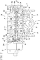
Fig. 2] Fig. 2 is a cross-sectional view illustrating the manifold-type electromagnetic valve ofFig. 1 . - [
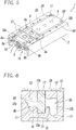
Fig. 3] Fig. 3 is an exploded perspective view illustrating the manifold base. - [
Fig. 4] Fig. 4 is a perspective view illustrating the manifold base in which silencers are mounted in a base body from the state illustrated inFig. 3 . - [
Fig. 5] Fig. 5 is a perspective view illustrating a state in which gaskets are mounted on valve mounting regions of the manifold base illustrated inFig. 4 . - [
Fig. 6] Fig. 6 is an enlarged cross-sectional view illustrating part of an air discharge channel ofFig. 2 . - A manifold base for solenoid valve according to the present invention will be described in detail with reference to the drawings.
Figs. 1 to 6 are views illustrating an embodiment of amanifold base 1 for solenoid valve according to the present invention and an embodiment of a manifold-type electromagnetic valve formed by using themanifold base 1. - As illustrated in
Figs. 1 and2 , themanifold base 1 on which the plurality ofsolenoid valves 30 are mounted constitutes the manifold-type electromagnetic valve. Themanifold base 1 includes abase body 2. Thebase body 2 has avalve mounting surface 2A on which thesolenoid valves 30 are mounted side by side in the width direction of thesolenoid valves 30. Themanifold base 1 also includessilencers 50. Thesilencers 50 are installed inside thebase body 2 and attenuate exhaust noise of discharged air from eachsolenoid valve 30. - The
solenoid valves 30 are known five-port solenoid valves havingcorresponding pilot valves 31. Eachsolenoid valve 30 includes output ports A and B for outputting compressed air supplied from themanifold base 1 toward an actuator (not illustrated).Fig. 1 illustrates an example configuration in which fivesolenoid valves 30 are mounted on thebase body 2. Since the fivesolenoid valves 30 have an identical structure, onesolenoid valve 30 will be described here with reference toFig. 2 . - As illustrated in
Fig. 2 , eachsolenoid valve 30 is constituted by amain valve portion 32, afirst adapter portion 33 and asecond adapter portion 43, and apilot valve 31. Themain valve portion 32 is shaped substantially like a cuboid, and thefirst adapter portion 33 is connected to one end of themain valve portion 32 in the direction of an axis L1 (longitudinal direction) and thesecond adapter portion 43 is connected to the other end of themain valve portion 32. Thepilot valve 31 is connected to thefirst adapter portion 33. Themain valve portion 32 includes ahousing 32a that has avalve hole 34 passing therethrough in the direction of the axis L1. Thevalve hole 34 accommodates aspool 35. Thevalve hole 34 communicates with asupply hole 36, first andsecond discharge holes second output holes supply hole 36 and the twodischarge holes housing 32a, whereas the twooutput holes housing 32a via corresponding two output ports A and B. The bottom surface of thehousing 32a is a contact surface to be in contact with thevalve mounting surface 2A of thebase body 2. - The
supply hole 36 are formed substantially at the center of thehousing 32a in the longitudinal direction thereof, and thedischarge holes supply hole 36. In addition, thefirst output hole 38a is formed between thesupply hole 36 and thefirst discharge hole 37a in the longitudinal direction of thehousing 32a, and thesecond output hole 38b is formed between thesupply hole 36 and thesecond discharge hole 37b. Thespool 35 slides inside thevalve hole 34 in the axial direction, which thereby switches channel connection among these holes. - The
first adapter portion 33 and thesecond adapter portion 43 haverespective bodies first adapter portion 33 has afirst cylinder chamber 39 defined by the surface of thebody 33a that faces themain valve portion 32. Thesecond adapter portion 43 has asecond cylinder chamber 40 defined by the surface of thebody 43a that faces themain valve portion 32. Thefirst cylinder chamber 39 and thesecond cylinder chamber 40 communicate with thevalve hole 34. Thefirst cylinder chamber 39 accommodates afirst piston 41, and thesecond cylinder chamber 40 accommodates asecond piston 42. Thefirst piston 41 and thesecond piston 42 are connected respectively to one end and the other end of thespool 35 in the axial direction thereof. The cylinder diameter of thefirst cylinder chamber 39 is larger than that of thesecond cylinder chamber 40, and accordingly thefirst piston 41 accommodated in thefirst cylinder chamber 39 is made larger in diameter than thesecond piston 42 accommodated in thesecond cylinder chamber 40. - A
first pressure chamber 39a formed within the first cylinder chamber 39 (the left chamber with respect to thefirst piston 41 inFig. 2 ) communicates with thesupply hole 36 via thepilot valve 31. Thepilot valve 31, which is a three-port solenoid valve, causes thefirst pressure chamber 39a to communicate with thesupply hole 36 when thepilot valve 31 is on, and thepilot valve 31 causes thefirst pressure chamber 39a to block communication with thesupply hole 36 and to open to the atmosphere when thepilot valve 31 is off. On the other hand, asecond pressure chamber 40a formed within the second cylinder chamber 40 (the right chamber with respect to thesecond piston 42 inFig. 2 ) is continuously in communication with thesupply hole 36. In addition,chambers 39b and 40b, which are chambers withinrespective cylinder chambers spool 35, are continuously in communication with the atmosphere. - In the
solenoid valve 30 configured as above, turning thepilot valve 31 on or off supplies pilot air to or discharges pilot air from thefirst pressure chamber 39a of thefirst cylinder chamber 39. Consequently, thespool 35 is reciprocally driven within thevalve hole 34 due to the difference between forces generated by air pressure acting on thelarge piston 41 and thesmall piston 42, which thereby switches the connection state among theholes Reference numeral 45 inFig. 2 denotes an operation member for manual operation. The operation member is provided for manually switching the connection state of the holes when thepilot valve 31 is on. - Note that since the structure of the
above solenoid valve 30 is known and not directly related to the gist of the present invention, further description will be omitted. - Next, the
manifold base 1 on which thesolenoid valves 30 are mounted will be described. - As illustrated in
Fig. 1 and inFigs. 3 to 5 , thebase body 2 constituting themanifold base 1 is a block-like member that is formed, for example by casting, into an elongated cuboid extending in the direction of an axis L2. Thebase body 2 has a flat top surface that is formed into thevalve mounting surface 2A on which thesolenoid valves 30 are mounted. As indicated by a chain line inFig. 4 , multiplevalve mounting regions 3 for each mounting asolenoid valve 30 are disposed on thevalve mounting surface 2A. Thevalve mounting regions 3 are arranged in a row in the longitudinal direction (in the direction of the axis L2) of thebase body 2. - In the present embodiment, the
valve mounting surface 2A is divided into fivevalve mounting regions 3, which are configured to arrange fivesolenoid valves 30 side by side. Note that thevalve mounting regions 3 are not clearly divided by a mark such as a border line but may be divided by any suitable marks if necessary. Portions denoted byreference 4a inFigs. 3 to 5 are threaded holes for fixing thesolenoid valves 30 onto thebase body 2 with fixingscrews 4b. In the illustrated example, two threadedholes 4a are provided at diagonal positions within eachvalve mounting region 3, and the two threadedholes 4a define eachvalve mounting region 3. The length of thebase body 2 in the lateral direction (width direction) thereof is set substantially equal to the length of thehousing 32a of thesolenoid valve 30 in the direction of the axis L1 (seeFig. 1 orFig. 2 ). - As illustrated in
Figs. 2 to 5 , a mainair supply channel 5 and branchedair supply channels 6 for supplying compressed air to thesolenoid valves 30 are formed inside thebase body 2. The mainair supply channel 5 is a channel for supplying compressed air simultaneously to the plurality ofsolenoid valves 30. The branchedair supply channels 6 are channels that are branched from the mainair supply channel 5 and open at respectivevalve mounting regions 3 of thevalve mounting surface 2A. The mainair supply channel 5 has a substantially circular cross section and passes through thebase body 2 in the longitudinal direction thereof at a central position of thebase body 2 in the lateral direction (width direction) thereof. The mainair supply channel 5 hasend openings 7 that open at both end surfaces of thebase body 2. A female thread is formed on the inner circumferential wall of the mainair supply channel 5 at eachend opening 7. An instant connection-type pipe joint having a male thread formed on the outer circumferential surface, for example, can be installed by screwing in theend opening 7. - The branched
air supply channels 6 are channels for sending compressed air supplied from the mainair supply channel 5 toindividual solenoid valves 30. As illustrated inFig. 2 , the branchedair supply channels 6 pass straight through thebase body 2 between the inner circumferential wall of the mainair supply channel 5 and thevalve mounting surface 2A. Each branchedair supply channel 6 has a circular cross section as is similar to the mainair supply channel 5, and the diameter of the cross section is smaller than that of the mainair supply channel 5. In the present embodiment, as illustrated inFig. 4 , each branchedair supply channel 6 opens at a correspondingvalve mounting region 3, and accordingly a total of five branchedair supply channels 6 are formed in a row in the longitudinal direction of thebase body 2. In addition, each branchedair supply channel 6 opens at a central portion of thebase body 2, in other words, at a central portion of thevalve mounting surface 2A in the lateral direction thereof. - The
base body 2 also has a firstair discharge channel 8a and a secondair discharge channel 8b for discharging the air discharged from thesolenoid valves 30 out of thebase body 2. As illustrated inFig. 2 , the firstair discharge channel 8a and the secondair discharge channel 8b are shaped in symmetry in cross section and also in disposition with respect to the vertical plane passing through the axis L2 of the mainair supply channel 5. - The first
air discharge channel 8a is constituted by a firstmain channel 9a and a first communicatingopening 10a. The secondair discharge channel 8b is also constituted by a secondmain channel 9b and a second communicatingopening 10b. The first and secondmain channel base body 2 in a direction parallel to the direction of arranging the valve mounting regions 3 (i.e., the longitudinal direction of the base body 2). The first and second communicatingopening main channels valve mounting surface 2A of thebase body 2. In addition, thesilencers 50 for attenuating the exhaust noise of the air discharged from thesolenoid valves 30 engage respective first and second communicatingopening main channel 9a and the first communicatingopening 10a communicate with each other, and the secondmain channel 9b and the second communicatingopening 10b communicate with each other. - The following describes specific configurations of the first and second
main channels openings air discharge channels air discharge channel 8b will be described below with reference toFig. 6 , while the description on the firstair discharge channel 8a will be omitted. - The second
main channel 9b of the secondair discharge channel 8b is formed so as to have abottom wall 11, right and leftside walls bottom wall 11, andtop wall 13 that is connected to the top ends of the right and leftside walls valve mounting surface 2A. The second communicatingopening 10b is formed in thetop wall 13 so as to extend from one end of thebase body 2 to the other end. The opening width of the second communicatingopening 10b is constant over the entire length. - The
side wall 12a, which is one of the side walls, of the secondmain channel 9b is formed as an arcuate surface that is formed concentrically with the circular circumferential wall of the main air supply channel 5 (seeFig. 2 ). Theside wall 12b, which is the other side wall, has a flat surface extending vertically along the side surface of thebase body 2. Theside wall 12b extends to a level below theside wall 12a. Accordingly, thebottom wall 11 declines from left to right as illustrated. - A pair of
support walls 15 are formed on the bottom of the secondmain channel 9b in such a manner that thesupport walls 15 stand vertically in a direction from thebottom wall 11 towardtop wall 13 and in parallel with each other. Asupport groove 15a is formed between thesupport walls 15. As thesupport walls 15 extend from one end of thebase body 2 to the other end, thesupport groove 15a also extends from one end of thebase body 2 to the other end. Thesupport groove 15a is formed for supporting the bottom end of asilencer 50. Thesupport groove 15a is positioned directly below the second communicatingopening 10b and has a constant width over the entire length of thesupport groove 15a. The width of thesupport groove 15a is substantially equal to the width of the second communicatingopening 10b. - The top ends of
respective support walls 15 are shaped into flat surfaces having the same height. The top ends of inner surfaces of thesupport walls 15, in other words, the top ends of walls of thesupport groove 15a, are chamfered. - As illustrated in
Figs. 2 to 6 , the first and second communicatingopenings valve mounting surface 2A so as to successively cross multiplevalve mounting regions 3 on thevalve mounting surface 2A. More specifically, the first and second communicatingopenings valve mounting surface 2A to correspondingmain channels openings main channels valve mounting surface 2A located thereabove. In addition, the first and second communicatingopenings main channels Fig. 4 ). Moreover, the two communicatingopenings base body 2 so as to extend parallel to each other with the branchedair supply channels 6 interposed therebetween. - With this configuration, when each
solenoid valve 30 is mounted on thevalve mounting surface 2A, the first communicatingopening 10a is connected to thefirst discharge hole 37a of thesolenoid valve 30, and the second communicatingopening 10b is connected to thesecond discharge hole 37b of the solenoid valve 30 (seeFig. 2 ). - Note that in the present embodiment, the opening widths of the first and second communicating
openings side walls main channels solenoid valve 30. -
Engagement protrusions 17 are formed on the walls of the first and second communicatingopenings respective silencers 50 installed in the first and second communicatingopenings silencers 50 coming off or being displaced from the first and second communicatingopenings openings engagement protrusion 17 is formed on one of the opposing walls of each of the communicatingopenings engagement protrusion 17 has a circular cross section, which enables smooth attachment/detachment of thesilencer 50 during replacement and suppresses the likelihood of thesilencer 50 being damaged or broken. - As illustrated in
Figs. 2 and3 , eachsilencer 50 is formed as a single body made of a porous noise reduction material having air permeability. More specifically, thesilencer 50 is formed into an elongated stick (square bar) having a rectangular cross section with a longitudinal length and a lateral length. Thesilencer 50 is installed in each of the first and second communicatingopenings silencer 50 is substantially equal to each width of the first and second communicatingopenings silencer 50 is substantially equal to the direct distance between the bottom of eachsupport groove 15a and thevalve mounting surface 2A. - In the state in which the
silencer 50 having such dimensions engages each of the first and second communicatingopenings silencer 50 extends from thevalve mounting surface 2A to the bottom of eachsupport groove 15a. The top portion of thesilencer 50 is supported by each of the communicatingopenings silencer 50 is supported by eachsupport groove 15a. Thus, the top surface of thesilencer 50 and thevalve mounting surface 2A are substantially flush with each other. The first and secondmain channels silencer 50 into two regions. The air discharged from thesolenoid valves 30 passes through thesilencer 50 and flows into cavities formed in both side regions of thesilencer 50 in each of themain channels - A cellular porous medium having interconnecting cells or a fibrous aggregate formed by entangled fibers, for example, can be preferably used as the noise reduction material. However, the noise reduction material is not limited to such materials.
- As illustrated in
Fig. 3 , a pair of mountingholes 60 that pass through thebase body 2 from thevalve mounting surface 2A to the bottom surface thereof is formed at one end portion of thebase body 2 in the longitudinal direction and also at the other end portion. These mountingholes 60 are used to fix thebase body 2 at a predetermined installation place by inserting mounting members such as screws. The mounting holes 60 are formed at positions adjacent to the first and second communicatingopenings silencer 50 along the axis L2 is shorter than the length of thebase body 2 in the longitudinal direction thereof. More specifically, the length of eachsilencer 50 is shorter than the distance between two mountingholes 60 located longitudinally at one and the other end portions of thebase body 2 along each of the communicatingopening - Note that a pair of right and left thinning
grooves 14 are formed at the bottom side of thebase body 2 along respectiveair discharge channels main channels base body 2 to the other end in the longitudinal direction. The thinninggrooves 14 are recessed into thebase body 2 in the height direction so as to leave intact the portion of thebase body 2 in which the mainair supply channel 5 and themain channels air discharge channels grooves 14 can reduce the weight of thebase body 2 and accordingly reduce the production cost. As a result of providing the thinninggrooves 14, an arcuate bottom 16 is formed on the bottom surface of thebase body 2 at the laterally central position. The arcuate bottom 16 has an arcuate surface formed concentrically with the opening of the mainair supply channel 5. In addition, aprotrusion 18 is formed on the arcuate bottom 16 so as to extend in the longitudinal direction of thebase body 2. Theprotrusion 18 serves as a foot when thebase body 2 is installed at an installation place. - The following specifically describes a manifold-type electromagnetic valve in which the plurality of
solenoid valves 30 are mounted on themanifold base 1 having the above-described configuration. Note that althoughsolenoid valves 30 are mounted on all of thevalve mounting regions 3 of thevalve mounting surface 2A inFig. 1 , asingle solenoid valve 30 will be described below since thesesolenoid valves 30 substantially has the same configuration as described above. Note that specific operations of thesolenoid valve 30 having the above configuration are known in the art, and accordingly description on the specific operations will be omitted. In addition, depending on the number of actuators to be controlled, the number ofsolenoid valves 30 may be less than the number ofvalve mounting regions 3 formed on thevalve mounting surface 2A. In this case, plugs are used to airtightly close the branchedair supply channels 6 that open in unusedvalve mounting regions 3. Alternatively, sealing members, such as plates, may be used to cover the unusedvalve mounting regions 3 airtightly. - In assembling the above manifold-type electromagnetic valve, two
silencers 50 are first pushed into corresponding first and second communicatingopenings Fig. 3 , from above thevalve mounting surface 2A of thebase body 2 in the directions indicated by downward pointing arrows. At this time, as illustrated inFig. 2 , thesilencers 50 are pushed so as to come into contact with respective bottom surfaces ofsupport grooves 15a of the first and secondmain channels silencers 50 engage thesupport grooves 15a and are thereby supported, while the top portions of thesilencers 50 are supported by the first and second communicatingopenings silencers 50 become substantially flush with thevalve mounting surface 2A. Here, thesilencers 50 engage theengagement protrusions 17. - Next, as illustrated in
Fig. 5 , a sealingmember 51, such as a gasket, is disposed on each of thevalve mounting regions 3 ofvalve mounting surface 2A of thebase body 2, and eachsolenoid valve 30 is fixed onto thebase body 2 with the sealingmember 51 interposed therebetween. In the state in which thesolenoid valve 30 is mounted, as illustrated inFig. 2 , thesupply hole 36 of thesolenoid valve 30 communicates with a branchedair supply channel 6 of thebase body 2, and the first and second discharge holes 37a and 37b of thesolenoid valve 30 communicate with corresponding first and second communicatingopenings base body 2. - Note that the first and second output ports A and B of the
solenoid valve 30 are connected, for example, to respective pressure chambers of a pneumatic actuator such as a double acting cylinder (not illustrated). In addition, compressed air is supplied to the mainair supply channel 5 of thebase body 2 from a pneumatic source (not illustrated). - When the
pilot valve 31 is in the non-energized state (OFF state), as illustrated inFig. 2 , thespool 35 is urged in one direction (in the leftward direction inFig. 2 ), which causes thesupply hole 36 of thesolenoid valve 30 to communicate with thesecond output hole 38b of the second output port B and also causes thefirst discharge hole 37a to communicate with thefirst output hole 38a of the first output port A. - This is a first communication state. In the first communication state, compressed air supplied from the main
air supply channel 5 to thesupply hole 36 via abranched supply channel 6 is output from the second output port B to the actuator, while compressed air from the first output port A, in other words, discharged air from the actuator, is discharged out of the base body 2 (to the atmosphere) through the firstair discharge channel 8a of thebase body 2, in other words, through the first communicatingopening 10a and the firstmain channel 9a. Here, the discharged air is discharged through the firstmain channel 9a to the atmosphere after the exhaust noise is attenuated (absorbed) by thesilencer 50 installed in the first communicatingopening 10a. - On the contrary, when the
pilot valve 31 is in the energized state (ON state), thespool 35 is urged in the other direction (in the rightward direction inFig. 2 ), which causes thesupply hole 36 to communicate with thefirst output hole 38a of the first output port A and also causes thesecond discharge hole 37b to communicate with thesecond output hole 38b of the second output port B. - This is a second communication state. In the second communication state, compressed air supplied to the
supply hole 36 is output from the first output port A to the actuator, while compressed air from the second output port B, in other words, discharged air from the actuator, is discharged out of thebase body 2 through the secondair discharge channel 8b of thebase body 2, in other words, through the second communicatingopening 10b and the secondmain channel 9b. Here, the discharged air is discharged through the secondmain channel 9b to the atmosphere after the exhaust noise is attenuated (absorbed) by thesilencer 50 installed in the second communicatingopening 10b. - As described above, the
manifold base 1 is configured such that thesilencers 50 for attenuating the exhaust noise of the discharged air from thesolenoid valves 30 are installed in respective first and second communicatingopenings valve mounting surface 2A of thebase body 2. In other words, thebase body 2 is designed so as to enable thesilencers 50 to be embedded therein in advance. As a result, compared with a known manifold base in which a silencer needs to be added later to the opening of the main air discharge channel of the manifold base, themanifold base 1 enables the silencers to be mounted thereon securely and reliably. Moreover, themanifold base 1 enables, for example, structural simplification or size and weight reduction of thebase body 2, in other words, themanifold base 1 enables streamlined designing of a manifold base equipped with a silencer. - The manifold base according to the present invention and the manifold-type electromagnetic valve using the manifold base have been described in detail. However, the present invention is not limited to the above embodiment but may be subjected to various design alterations without departing from the gist of the appended claims.
- For example, in the present embodiment, single pilot-
type solenoid valves 30 each equipped with asingle pilot valve 31 are mounted on thevalve mounting surface 2A of the base body. However, double pilot-type solenoid valves each having two pilot valves may be mounted thereon. - In addition, the first and second communicating
openings valve mounting regions 3 on thevalve mounting surface 2A. However, it may be sufficient that the first and second communicatingopenings valve mounting regions 3. For example, the first and second communicatingopenings valve mounting regions 3. Alternatively, thevalve mounting regions 3 may be grouped into multiple groups, and the first and second communicatingopenings valve mounting regions 3 included in each group. In this case, thesilencers 50 are divided into multiple bodies in accordance with the number of the communicatingopenings - Moreover, the
silencer 50 has been described as a single body made of a noise reduction material. However, it may be sufficient that thesilencer 50 is formed such that the noise reduction material is disposed at least at each of thevalve mounting regions 3 on thevalve mounting surface 2A. For example, in the case of thesilencer 50 installed in each of the communicatingopenings valve mounting regions 3, thesilencer 50 may be formed by using the noise reduction members and non-permeable members. In other words, thesilencer 50 may be formed by combining the noise reduction members with non-permeable members in such a manner that the noise reduction members are disposed atvalve mounting regions 3 and the non-permeable members are disposed between adjacentvalve mounting regions 3. -
- 1
- manifold base
- 2
- base body
- 2A
- valve mounting surface
- 3
- valve mounting region
- 5
- main air supply channel
- 6
- branched air supply channel
- 8a, 8b
- air discharge channel
- 9a, 9b
- main channel
- 10a, 10b
- communicating opening
- 15
- support walls
- 15a
- support groove
- 30
- solenoid valve
- 50
- silencer
Claims (8)
- A manifold base for mounting plurality of solenoid valves thereon in an arranged manner, the manifold base comprising:a base body havinga valve mounting surface on which multiple valve mounting regions for mounting the solenoid valves thereon are arranged in a row,an air supply channel through which compressed air is supplied to the solenoid valves, andan air discharge channel through which air discharged from the solenoid valves is discharged to outside; anda silencer that attenuates exhaust noise of the discharged air, whereinthe air discharge channel is constituted bya main channel that passes through inside the base body in a direction of arranging the valve mounting regions in the row, anda communicating opening that opens at the valve mounting surface and enable the main channel to communicate with the valve mounting regions, andthe silencer is installed inside the communicating opening.
- The manifold base according to Claim 1, wherein
the communicating opening is formed as an elongated groove extending along the main channel, and
the silencer is formed into a square bar made of a porous noise reduction material having air permeability. - The manifold base according to Claim 2, wherein
the communicating opening is formed so as to successively cross all of the valve mounting regions, and
the silencer is accommodated inside the communicating opening in such a manner that the silencer successively crosses all of the valve mounting regions. - The manifold base according to Claim 2, wherein
a support groove is formed at a bottom of the main channel at a position opposing the communicating opening, and
the silencer has a bottom portion installed inside the support groove. - The manifold base according to Claim 4, wherein
the support groove is formed between a pair of support walls that stand on a bottom wall of the main channel and that extend parallel to each other. - The manifold base according to Claim 1, wherein
the air supply channel is constituted bya main air supply channel through which compressed air to be supplied to the solenoid valves is simultaneously circulated andmultiple branched air supply channels that are branched from the main air supply channel and that open at the valve mounting surface, andthe main air supply channel passes through inside the base body so as to extend parallel to the air discharge channel. - The manifold base according to Claim 6, wherein two air discharge channels are disposed in both side regions of the main air supply channel, respectively.
- A manifold-type electromagnetic valve comprising:the manifold base according to Claim 1, andsolenoid valves mounted on respective valve mounting regions of the valve mounting surface of the manifold base.
Applications Claiming Priority (2)
| Application Number | Priority Date | Filing Date | Title |
|---|---|---|---|
| JP2017027123A JP6819867B2 (en) | 2017-02-16 | 2017-02-16 | Manifold base for solenoid valve and solenoid valve assembly using it |
| PCT/JP2018/003887 WO2018150932A1 (en) | 2017-02-16 | 2018-02-06 | Manifold base for electromagnetic valve and manifold-type electromagnetic valve |
Publications (3)
| Publication Number | Publication Date |
|---|---|
| EP3584481A1 true EP3584481A1 (en) | 2019-12-25 |
| EP3584481A4 EP3584481A4 (en) | 2020-12-09 |
| EP3584481B1 EP3584481B1 (en) | 2023-07-26 |
Family
ID=63169340
Family Applications (1)
| Application Number | Title | Priority Date | Filing Date |
|---|---|---|---|
| EP18753889.7A Active EP3584481B1 (en) | 2017-02-16 | 2018-02-06 | Manifold base for electromagnetic valve and manifold-type electromagnetic valve |
Country Status (10)
| Country | Link |
|---|---|
| US (1) | US10900581B2 (en) |
| EP (1) | EP3584481B1 (en) |
| JP (1) | JP6819867B2 (en) |
| KR (1) | KR102475548B1 (en) |
| CN (1) | CN110291318B (en) |
| BR (1) | BR112019017081A2 (en) |
| MX (1) | MX2019009738A (en) |
| RU (1) | RU2019128857A (en) |
| TW (1) | TWI756364B (en) |
| WO (1) | WO2018150932A1 (en) |
Families Citing this family (7)
| Publication number | Priority date | Publication date | Assignee | Title |
|---|---|---|---|---|
| JP7454527B2 (en) * | 2021-06-25 | 2024-03-22 | Ckd株式会社 | solenoid valve manifold |
| CN113357432B (en) * | 2021-07-08 | 2022-06-21 | 河南航天液压气动技术有限公司 | High-precision easy-to-adjust silencing balance valve |
| US12060898B2 (en) * | 2021-12-15 | 2024-08-13 | Ford Global Technologies, Llc | Unitized valve body having connection orifices |
| CN114151583A (en) * | 2021-12-30 | 2022-03-08 | 深圳市东吉联医疗科技有限公司 | Electromagnetic valve assembly of air wave physiotherapy instrument |
| DE102022106225A1 (en) * | 2022-03-17 | 2023-09-21 | Festo Se & Co. Kg | Valve module system |
| JP7705823B2 (en) * | 2022-04-08 | 2025-07-10 | Ckd株式会社 | Solenoid valve manifold |
| WO2024218140A1 (en) * | 2023-04-19 | 2024-10-24 | BSH Hausgeräte GmbH | Gas main and a gas cooking appliance |
Family Cites Families (15)
| Publication number | Priority date | Publication date | Assignee | Title |
|---|---|---|---|---|
| US3504704A (en) * | 1968-04-29 | 1970-04-07 | Beckett Harcum Co | Valve and control assembly |
| DE3326802C2 (en) * | 1983-07-26 | 1986-03-20 | Festo KG, 7300 Esslingen | Terminal block |
| JPH0227074U (en) * | 1988-08-09 | 1990-02-22 | ||
| JPH0743447Y2 (en) * | 1988-10-14 | 1995-10-09 | 株式会社巴技術研究所 | Valve operating speed controller |
| JP3088440B2 (en) * | 1990-09-11 | 2000-09-18 | エスエムシー株式会社 | Manifold with silencing function |
| DE4232628A1 (en) * | 1992-09-29 | 1994-03-31 | Herion Werke Kg | Directional control valve |
| JP3486238B2 (en) * | 1994-09-21 | 2004-01-13 | Smc株式会社 | Switching valve |
| JP4378627B2 (en) * | 2004-03-30 | 2009-12-09 | Smc株式会社 | Air servo cylinder |
| JP4482758B2 (en) | 2005-02-16 | 2010-06-16 | Smc株式会社 | Manifold base assembly |
| JP4919002B2 (en) | 2005-06-20 | 2012-04-18 | Smc株式会社 | Manifold solenoid valve assembly |
| CN100497963C (en) * | 2005-06-20 | 2009-06-10 | Smc株式会社 | Manifold-type solenoid valve assembly |
| JP2009257554A (en) | 2008-04-21 | 2009-11-05 | Smc Corp | Manifold for solenoid valve |
| CN103459855B (en) * | 2011-03-28 | 2016-03-16 | 株式会社小金井 | ejector |
| CN106555656A (en) * | 2015-09-30 | 2017-04-05 | 重庆展瑞汽车配件厂 | A kind of automobile gas exhausting manifold branch hush pipe |
| WO2017104179A1 (en) * | 2015-12-14 | 2017-06-22 | Smc株式会社 | Manifold assembly for electromagnetic valve and electromagentic valve cluster using same |
-
2017
- 2017-02-16 JP JP2017027123A patent/JP6819867B2/en active Active
-
2018
- 2018-02-06 WO PCT/JP2018/003887 patent/WO2018150932A1/en not_active Ceased
- 2018-02-06 KR KR1020197025514A patent/KR102475548B1/en active Active
- 2018-02-06 MX MX2019009738A patent/MX2019009738A/en unknown
- 2018-02-06 US US16/485,542 patent/US10900581B2/en active Active
- 2018-02-06 CN CN201880012047.6A patent/CN110291318B/en active Active
- 2018-02-06 RU RU2019128857A patent/RU2019128857A/en unknown
- 2018-02-06 BR BR112019017081A patent/BR112019017081A2/en not_active IP Right Cessation
- 2018-02-06 EP EP18753889.7A patent/EP3584481B1/en active Active
- 2018-02-12 TW TW107104957A patent/TWI756364B/en active
Also Published As
| Publication number | Publication date |
|---|---|
| TWI756364B (en) | 2022-03-01 |
| CN110291318B (en) | 2021-10-15 |
| JP2018132144A (en) | 2018-08-23 |
| KR102475548B1 (en) | 2022-12-08 |
| US10900581B2 (en) | 2021-01-26 |
| TW201835477A (en) | 2018-10-01 |
| MX2019009738A (en) | 2019-10-15 |
| EP3584481A4 (en) | 2020-12-09 |
| JP6819867B2 (en) | 2021-01-27 |
| US20200049271A1 (en) | 2020-02-13 |
| EP3584481B1 (en) | 2023-07-26 |
| KR20190117574A (en) | 2019-10-16 |
| RU2019128857A (en) | 2021-03-16 |
| WO2018150932A1 (en) | 2018-08-23 |
| CN110291318A (en) | 2019-09-27 |
| RU2019128857A3 (en) | 2021-06-21 |
| BR112019017081A2 (en) | 2020-04-07 |
Similar Documents
| Publication | Publication Date | Title |
|---|---|---|
| EP3584481B1 (en) | Manifold base for electromagnetic valve and manifold-type electromagnetic valve | |
| KR102540684B1 (en) | Manifold assembly for solenoid valve and solenoid valve assembly using the same | |
| KR100345533B1 (en) | Valve device | |
| EP0703391A1 (en) | Rail-mounted aggregate valve | |
| JP6327418B2 (en) | Dual 4-port solenoid valve | |
| JP6467711B2 (en) | Multiple integrated manifold valve | |
| US5699834A (en) | Manifold-type solenoid valves | |
| JP3837205B2 (en) | Sealed switching valve assembly | |
| US5860445A (en) | Transfer valve manifold | |
| US8651140B2 (en) | Valve arrangement for different flow rate categories | |
| CN101460746B (en) | Valve arrangement | |
| KR100286706B1 (en) | Switching Valve Connection_ | |
| JP3850926B2 (en) | Pilot type switching valve | |
| US8833396B2 (en) | Multiple electromagnetic valve | |
| US11828305B2 (en) | Multi-control valve device | |
| KR100302412B1 (en) | Pilot Switching Valve | |
| EP3822523A1 (en) | Spool valve | |
| EP3845767B1 (en) | Valve group |
Legal Events
| Date | Code | Title | Description |
|---|---|---|---|
| STAA | Information on the status of an ep patent application or granted ep patent |
Free format text: STATUS: THE INTERNATIONAL PUBLICATION HAS BEEN MADE |
|
| PUAI | Public reference made under article 153(3) epc to a published international application that has entered the european phase |
Free format text: ORIGINAL CODE: 0009012 |
|
| STAA | Information on the status of an ep patent application or granted ep patent |
Free format text: STATUS: REQUEST FOR EXAMINATION WAS MADE |
|
| 17P | Request for examination filed |
Effective date: 20190821 |
|
| AK | Designated contracting states |
Kind code of ref document: A1 Designated state(s): AL AT BE BG CH CY CZ DE DK EE ES FI FR GB GR HR HU IE IS IT LI LT LU LV MC MK MT NL NO PL PT RO RS SE SI SK SM TR |
|
| AX | Request for extension of the european patent |
Extension state: BA ME |
|
| DAV | Request for validation of the european patent (deleted) | ||
| DAX | Request for extension of the european patent (deleted) | ||
| A4 | Supplementary search report drawn up and despatched |
Effective date: 20201111 |
|
| RIC1 | Information provided on ipc code assigned before grant |
Ipc: F16K 47/02 20060101AFI20201105BHEP Ipc: F16K 27/00 20060101ALI20201105BHEP Ipc: F16K 31/06 20060101ALI20201105BHEP |
|
| GRAP | Despatch of communication of intention to grant a patent |
Free format text: ORIGINAL CODE: EPIDOSNIGR1 |
|
| STAA | Information on the status of an ep patent application or granted ep patent |
Free format text: STATUS: GRANT OF PATENT IS INTENDED |
|
| INTG | Intention to grant announced |
Effective date: 20230224 |
|
| GRAS | Grant fee paid |
Free format text: ORIGINAL CODE: EPIDOSNIGR3 |
|
| GRAA | (expected) grant |
Free format text: ORIGINAL CODE: 0009210 |
|
| STAA | Information on the status of an ep patent application or granted ep patent |
Free format text: STATUS: THE PATENT HAS BEEN GRANTED |
|
| RIN1 | Information on inventor provided before grant (corrected) |
Inventor name: YOSHIDA, MASARU Inventor name: YOSHIMURA, SHINICHI Inventor name: MIYAZOE, SHINJI |
|
| AK | Designated contracting states |
Kind code of ref document: B1 Designated state(s): AL AT BE BG CH CY CZ DE DK EE ES FI FR GB GR HR HU IE IS IT LI LT LU LV MC MK MT NL NO PL PT RO RS SE SI SK SM TR |
|
| REG | Reference to a national code |
Ref country code: CH Ref legal event code: EP |
|
| REG | Reference to a national code |
Ref country code: DE Ref legal event code: R096 Ref document number: 602018054072 Country of ref document: DE |
|
| REG | Reference to a national code |
Ref country code: IE Ref legal event code: FG4D |
|
| REG | Reference to a national code |
Ref country code: LT Ref legal event code: MG9D |
|
| REG | Reference to a national code |
Ref country code: NL Ref legal event code: MP Effective date: 20230726 |
|
| REG | Reference to a national code |
Ref country code: AT Ref legal event code: MK05 Ref document number: 1592262 Country of ref document: AT Kind code of ref document: T Effective date: 20230726 |
|
| PG25 | Lapsed in a contracting state [announced via postgrant information from national office to epo] |
Ref country code: NL Free format text: LAPSE BECAUSE OF FAILURE TO SUBMIT A TRANSLATION OF THE DESCRIPTION OR TO PAY THE FEE WITHIN THE PRESCRIBED TIME-LIMIT Effective date: 20230726 |
|
| PG25 | Lapsed in a contracting state [announced via postgrant information from national office to epo] |
Ref country code: GR Free format text: LAPSE BECAUSE OF FAILURE TO SUBMIT A TRANSLATION OF THE DESCRIPTION OR TO PAY THE FEE WITHIN THE PRESCRIBED TIME-LIMIT Effective date: 20231027 |
|
| PG25 | Lapsed in a contracting state [announced via postgrant information from national office to epo] |
Ref country code: IS Free format text: LAPSE BECAUSE OF FAILURE TO SUBMIT A TRANSLATION OF THE DESCRIPTION OR TO PAY THE FEE WITHIN THE PRESCRIBED TIME-LIMIT Effective date: 20231126 |
|
| PG25 | Lapsed in a contracting state [announced via postgrant information from national office to epo] |
Ref country code: SE Free format text: LAPSE BECAUSE OF FAILURE TO SUBMIT A TRANSLATION OF THE DESCRIPTION OR TO PAY THE FEE WITHIN THE PRESCRIBED TIME-LIMIT Effective date: 20230726 Ref country code: RS Free format text: LAPSE BECAUSE OF FAILURE TO SUBMIT A TRANSLATION OF THE DESCRIPTION OR TO PAY THE FEE WITHIN THE PRESCRIBED TIME-LIMIT Effective date: 20230726 Ref country code: PT Free format text: LAPSE BECAUSE OF FAILURE TO SUBMIT A TRANSLATION OF THE DESCRIPTION OR TO PAY THE FEE WITHIN THE PRESCRIBED TIME-LIMIT Effective date: 20231127 Ref country code: NO Free format text: LAPSE BECAUSE OF FAILURE TO SUBMIT A TRANSLATION OF THE DESCRIPTION OR TO PAY THE FEE WITHIN THE PRESCRIBED TIME-LIMIT Effective date: 20231026 Ref country code: LV Free format text: LAPSE BECAUSE OF FAILURE TO SUBMIT A TRANSLATION OF THE DESCRIPTION OR TO PAY THE FEE WITHIN THE PRESCRIBED TIME-LIMIT Effective date: 20230726 Ref country code: LT Free format text: LAPSE BECAUSE OF FAILURE TO SUBMIT A TRANSLATION OF THE DESCRIPTION OR TO PAY THE FEE WITHIN THE PRESCRIBED TIME-LIMIT Effective date: 20230726 Ref country code: IS Free format text: LAPSE BECAUSE OF FAILURE TO SUBMIT A TRANSLATION OF THE DESCRIPTION OR TO PAY THE FEE WITHIN THE PRESCRIBED TIME-LIMIT Effective date: 20231126 Ref country code: HR Free format text: LAPSE BECAUSE OF FAILURE TO SUBMIT A TRANSLATION OF THE DESCRIPTION OR TO PAY THE FEE WITHIN THE PRESCRIBED TIME-LIMIT Effective date: 20230726 Ref country code: GR Free format text: LAPSE BECAUSE OF FAILURE TO SUBMIT A TRANSLATION OF THE DESCRIPTION OR TO PAY THE FEE WITHIN THE PRESCRIBED TIME-LIMIT Effective date: 20231027 Ref country code: FI Free format text: LAPSE BECAUSE OF FAILURE TO SUBMIT A TRANSLATION OF THE DESCRIPTION OR TO PAY THE FEE WITHIN THE PRESCRIBED TIME-LIMIT Effective date: 20230726 Ref country code: AT Free format text: LAPSE BECAUSE OF FAILURE TO SUBMIT A TRANSLATION OF THE DESCRIPTION OR TO PAY THE FEE WITHIN THE PRESCRIBED TIME-LIMIT Effective date: 20230726 |
|
| PG25 | Lapsed in a contracting state [announced via postgrant information from national office to epo] |
Ref country code: PL Free format text: LAPSE BECAUSE OF FAILURE TO SUBMIT A TRANSLATION OF THE DESCRIPTION OR TO PAY THE FEE WITHIN THE PRESCRIBED TIME-LIMIT Effective date: 20230726 |
|
| PG25 | Lapsed in a contracting state [announced via postgrant information from national office to epo] |
Ref country code: ES Free format text: LAPSE BECAUSE OF FAILURE TO SUBMIT A TRANSLATION OF THE DESCRIPTION OR TO PAY THE FEE WITHIN THE PRESCRIBED TIME-LIMIT Effective date: 20230726 |
|
| REG | Reference to a national code |
Ref country code: DE Ref legal event code: R097 Ref document number: 602018054072 Country of ref document: DE |
|
| PG25 | Lapsed in a contracting state [announced via postgrant information from national office to epo] |
Ref country code: SM Free format text: LAPSE BECAUSE OF FAILURE TO SUBMIT A TRANSLATION OF THE DESCRIPTION OR TO PAY THE FEE WITHIN THE PRESCRIBED TIME-LIMIT Effective date: 20230726 Ref country code: RO Free format text: LAPSE BECAUSE OF FAILURE TO SUBMIT A TRANSLATION OF THE DESCRIPTION OR TO PAY THE FEE WITHIN THE PRESCRIBED TIME-LIMIT Effective date: 20230726 Ref country code: ES Free format text: LAPSE BECAUSE OF FAILURE TO SUBMIT A TRANSLATION OF THE DESCRIPTION OR TO PAY THE FEE WITHIN THE PRESCRIBED TIME-LIMIT Effective date: 20230726 Ref country code: EE Free format text: LAPSE BECAUSE OF FAILURE TO SUBMIT A TRANSLATION OF THE DESCRIPTION OR TO PAY THE FEE WITHIN THE PRESCRIBED TIME-LIMIT Effective date: 20230726 Ref country code: DK Free format text: LAPSE BECAUSE OF FAILURE TO SUBMIT A TRANSLATION OF THE DESCRIPTION OR TO PAY THE FEE WITHIN THE PRESCRIBED TIME-LIMIT Effective date: 20230726 Ref country code: CZ Free format text: LAPSE BECAUSE OF FAILURE TO SUBMIT A TRANSLATION OF THE DESCRIPTION OR TO PAY THE FEE WITHIN THE PRESCRIBED TIME-LIMIT Effective date: 20230726 Ref country code: SK Free format text: LAPSE BECAUSE OF FAILURE TO SUBMIT A TRANSLATION OF THE DESCRIPTION OR TO PAY THE FEE WITHIN THE PRESCRIBED TIME-LIMIT Effective date: 20230726 |
|
| PG25 | Lapsed in a contracting state [announced via postgrant information from national office to epo] |
Ref country code: IT Free format text: LAPSE BECAUSE OF FAILURE TO SUBMIT A TRANSLATION OF THE DESCRIPTION OR TO PAY THE FEE WITHIN THE PRESCRIBED TIME-LIMIT Effective date: 20230726 |
|
| PLBE | No opposition filed within time limit |
Free format text: ORIGINAL CODE: 0009261 |
|
| STAA | Information on the status of an ep patent application or granted ep patent |
Free format text: STATUS: NO OPPOSITION FILED WITHIN TIME LIMIT |
|
| 26N | No opposition filed |
Effective date: 20240429 |
|
| PG25 | Lapsed in a contracting state [announced via postgrant information from national office to epo] |
Ref country code: SI Free format text: LAPSE BECAUSE OF FAILURE TO SUBMIT A TRANSLATION OF THE DESCRIPTION OR TO PAY THE FEE WITHIN THE PRESCRIBED TIME-LIMIT Effective date: 20230726 |
|
| PG25 | Lapsed in a contracting state [announced via postgrant information from national office to epo] |
Ref country code: MC Free format text: LAPSE BECAUSE OF FAILURE TO SUBMIT A TRANSLATION OF THE DESCRIPTION OR TO PAY THE FEE WITHIN THE PRESCRIBED TIME-LIMIT Effective date: 20230726 |
|
| REG | Reference to a national code |
Ref country code: CH Ref legal event code: PL |
|
| PG25 | Lapsed in a contracting state [announced via postgrant information from national office to epo] |
Ref country code: LU Free format text: LAPSE BECAUSE OF NON-PAYMENT OF DUE FEES Effective date: 20240206 |
|
| PG25 | Lapsed in a contracting state [announced via postgrant information from national office to epo] |
Ref country code: CH Free format text: LAPSE BECAUSE OF NON-PAYMENT OF DUE FEES Effective date: 20240229 |
|
| GBPC | Gb: european patent ceased through non-payment of renewal fee |
Effective date: 20240206 |
|
| PG25 | Lapsed in a contracting state [announced via postgrant information from national office to epo] |
Ref country code: LU Free format text: LAPSE BECAUSE OF NON-PAYMENT OF DUE FEES Effective date: 20240206 Ref country code: CH Free format text: LAPSE BECAUSE OF NON-PAYMENT OF DUE FEES Effective date: 20240229 |
|
| PG25 | Lapsed in a contracting state [announced via postgrant information from national office to epo] |
Ref country code: BG Free format text: LAPSE BECAUSE OF FAILURE TO SUBMIT A TRANSLATION OF THE DESCRIPTION OR TO PAY THE FEE WITHIN THE PRESCRIBED TIME-LIMIT Effective date: 20230726 |
|
| PG25 | Lapsed in a contracting state [announced via postgrant information from national office to epo] |
Ref country code: BG Free format text: LAPSE BECAUSE OF FAILURE TO SUBMIT A TRANSLATION OF THE DESCRIPTION OR TO PAY THE FEE WITHIN THE PRESCRIBED TIME-LIMIT Effective date: 20230726 |
|
| REG | Reference to a national code |
Ref country code: BE Ref legal event code: MM Effective date: 20240229 |
|
| PG25 | Lapsed in a contracting state [announced via postgrant information from national office to epo] |
Ref country code: BE Free format text: LAPSE BECAUSE OF NON-PAYMENT OF DUE FEES Effective date: 20240229 |
|
| PG25 | Lapsed in a contracting state [announced via postgrant information from national office to epo] |
Ref country code: GB Free format text: LAPSE BECAUSE OF NON-PAYMENT OF DUE FEES Effective date: 20240206 |
|
| PG25 | Lapsed in a contracting state [announced via postgrant information from national office to epo] |
Ref country code: FR Free format text: LAPSE BECAUSE OF NON-PAYMENT OF DUE FEES Effective date: 20240229 |
|
| PG25 | Lapsed in a contracting state [announced via postgrant information from national office to epo] |
Ref country code: IE Free format text: LAPSE BECAUSE OF NON-PAYMENT OF DUE FEES Effective date: 20240206 |
|
| PG25 | Lapsed in a contracting state [announced via postgrant information from national office to epo] |
Ref country code: IE Free format text: LAPSE BECAUSE OF NON-PAYMENT OF DUE FEES Effective date: 20240206 Ref country code: GB Free format text: LAPSE BECAUSE OF NON-PAYMENT OF DUE FEES Effective date: 20240206 Ref country code: FR Free format text: LAPSE BECAUSE OF NON-PAYMENT OF DUE FEES Effective date: 20240229 Ref country code: BE Free format text: LAPSE BECAUSE OF NON-PAYMENT OF DUE FEES Effective date: 20240229 |
|
| PG25 | Lapsed in a contracting state [announced via postgrant information from national office to epo] |
Ref country code: CY Free format text: LAPSE BECAUSE OF FAILURE TO SUBMIT A TRANSLATION OF THE DESCRIPTION OR TO PAY THE FEE WITHIN THE PRESCRIBED TIME-LIMIT; INVALID AB INITIO Effective date: 20180206 |
|
| PG25 | Lapsed in a contracting state [announced via postgrant information from national office to epo] |
Ref country code: HU Free format text: LAPSE BECAUSE OF FAILURE TO SUBMIT A TRANSLATION OF THE DESCRIPTION OR TO PAY THE FEE WITHIN THE PRESCRIBED TIME-LIMIT; INVALID AB INITIO Effective date: 20180206 |
|
| PG25 | Lapsed in a contracting state [announced via postgrant information from national office to epo] |
Ref country code: TR Free format text: LAPSE BECAUSE OF FAILURE TO SUBMIT A TRANSLATION OF THE DESCRIPTION OR TO PAY THE FEE WITHIN THE PRESCRIBED TIME-LIMIT Effective date: 20230726 |
|
| PGFP | Annual fee paid to national office [announced via postgrant information from national office to epo] |
Ref country code: DE Payment date: 20260319 Year of fee payment: 9 |