EP3584447A1 - State quantity estimating device - Google Patents
State quantity estimating device Download PDFInfo
- Publication number
- EP3584447A1 EP3584447A1 EP18753903.6A EP18753903A EP3584447A1 EP 3584447 A1 EP3584447 A1 EP 3584447A1 EP 18753903 A EP18753903 A EP 18753903A EP 3584447 A1 EP3584447 A1 EP 3584447A1
- Authority
- EP
- European Patent Office
- Prior art keywords
- air
- impeller
- pressure
- state quantity
- outlet
- Prior art date
- Legal status (The legal status is an assumption and is not a legal conclusion. Google has not performed a legal analysis and makes no representation as to the accuracy of the status listed.)
- Withdrawn
Links
Images


Classifications
-
- F—MECHANICAL ENGINEERING; LIGHTING; HEATING; WEAPONS; BLASTING
- F02—COMBUSTION ENGINES; HOT-GAS OR COMBUSTION-PRODUCT ENGINE PLANTS
- F02D—CONTROLLING COMBUSTION ENGINES
- F02D41/00—Electrical control of supply of combustible mixture or its constituents
- F02D41/0002—Controlling intake air
- F02D41/0007—Controlling intake air for control of turbo-charged or super-charged engines
-
- G—PHYSICS
- G01—MEASURING; TESTING
- G01M—TESTING STATIC OR DYNAMIC BALANCE OF MACHINES OR STRUCTURES; TESTING OF STRUCTURES OR APPARATUS, NOT OTHERWISE PROVIDED FOR
- G01M15/00—Testing of engines
- G01M15/04—Testing internal-combustion engines
-
- F—MECHANICAL ENGINEERING; LIGHTING; HEATING; WEAPONS; BLASTING
- F02—COMBUSTION ENGINES; HOT-GAS OR COMBUSTION-PRODUCT ENGINE PLANTS
- F02B—INTERNAL-COMBUSTION PISTON ENGINES; COMBUSTION ENGINES IN GENERAL
- F02B39/00—Component parts, details, or accessories relating to, driven charging or scavenging pumps, not provided for in groups F02B33/00 - F02B37/00
- F02B39/16—Other safety measures for, or other control of, pumps
-
- F—MECHANICAL ENGINEERING; LIGHTING; HEATING; WEAPONS; BLASTING
- F02—COMBUSTION ENGINES; HOT-GAS OR COMBUSTION-PRODUCT ENGINE PLANTS
- F02D—CONTROLLING COMBUSTION ENGINES
- F02D45/00—Electrical control not provided for in groups F02D41/00 - F02D43/00
-
- F—MECHANICAL ENGINEERING; LIGHTING; HEATING; WEAPONS; BLASTING
- F04—POSITIVE - DISPLACEMENT MACHINES FOR LIQUIDS; PUMPS FOR LIQUIDS OR ELASTIC FLUIDS
- F04D—NON-POSITIVE-DISPLACEMENT PUMPS
- F04D17/00—Radial-flow pumps, e.g. centrifugal pumps; Helico-centrifugal pumps
- F04D17/08—Centrifugal pumps
- F04D17/10—Centrifugal pumps for compressing or evacuating
-
- F—MECHANICAL ENGINEERING; LIGHTING; HEATING; WEAPONS; BLASTING
- F04—POSITIVE - DISPLACEMENT MACHINES FOR LIQUIDS; PUMPS FOR LIQUIDS OR ELASTIC FLUIDS
- F04D—NON-POSITIVE-DISPLACEMENT PUMPS
- F04D25/00—Pumping installations or systems
- F04D25/02—Units comprising pumps and their driving means
- F04D25/04—Units comprising pumps and their driving means the pump being fluid-driven
-
- F—MECHANICAL ENGINEERING; LIGHTING; HEATING; WEAPONS; BLASTING
- F04—POSITIVE - DISPLACEMENT MACHINES FOR LIQUIDS; PUMPS FOR LIQUIDS OR ELASTIC FLUIDS
- F04D—NON-POSITIVE-DISPLACEMENT PUMPS
- F04D27/00—Control, e.g. regulation, of pumps, pumping installations or pumping systems specially adapted for elastic fluids
- F04D27/001—Testing thereof; Determination or simulation of flow characteristics; Stall or surge detection, e.g. condition monitoring
-
- F—MECHANICAL ENGINEERING; LIGHTING; HEATING; WEAPONS; BLASTING
- F02—COMBUSTION ENGINES; HOT-GAS OR COMBUSTION-PRODUCT ENGINE PLANTS
- F02B—INTERNAL-COMBUSTION PISTON ENGINES; COMBUSTION ENGINES IN GENERAL
- F02B2700/00—Measures relating to the combustion process without indication of the kind of fuel or with more than one fuel
- F02B2700/02—Four stroke engines
- F02B2700/025—Four stroke engines with measures for compressing the cylinder charge
-
- F—MECHANICAL ENGINEERING; LIGHTING; HEATING; WEAPONS; BLASTING
- F02—COMBUSTION ENGINES; HOT-GAS OR COMBUSTION-PRODUCT ENGINE PLANTS
- F02B—INTERNAL-COMBUSTION PISTON ENGINES; COMBUSTION ENGINES IN GENERAL
- F02B37/00—Engines characterised by provision of pumps driven at least for part of the time by exhaust
- F02B37/12—Control of the pumps
-
- F—MECHANICAL ENGINEERING; LIGHTING; HEATING; WEAPONS; BLASTING
- F02—COMBUSTION ENGINES; HOT-GAS OR COMBUSTION-PRODUCT ENGINE PLANTS
- F02D—CONTROLLING COMBUSTION ENGINES
- F02D2200/00—Input parameters for engine control
- F02D2200/02—Input parameters for engine control the parameters being related to the engine
- F02D2200/04—Engine intake system parameters
- F02D2200/0402—Engine intake system parameters the parameter being determined by using a model of the engine intake or its components
-
- F—MECHANICAL ENGINEERING; LIGHTING; HEATING; WEAPONS; BLASTING
- F02—COMBUSTION ENGINES; HOT-GAS OR COMBUSTION-PRODUCT ENGINE PLANTS
- F02D—CONTROLLING COMBUSTION ENGINES
- F02D2200/00—Input parameters for engine control
- F02D2200/02—Input parameters for engine control the parameters being related to the engine
- F02D2200/04—Engine intake system parameters
- F02D2200/0406—Intake manifold pressure
- F02D2200/0408—Estimation of intake manifold pressure
-
- F—MECHANICAL ENGINEERING; LIGHTING; HEATING; WEAPONS; BLASTING
- F02—COMBUSTION ENGINES; HOT-GAS OR COMBUSTION-PRODUCT ENGINE PLANTS
- F02D—CONTROLLING COMBUSTION ENGINES
- F02D2200/00—Input parameters for engine control
- F02D2200/02—Input parameters for engine control the parameters being related to the engine
- F02D2200/04—Engine intake system parameters
- F02D2200/0414—Air temperature
- F02D2200/0416—Estimation of air temperature
-
- F—MECHANICAL ENGINEERING; LIGHTING; HEATING; WEAPONS; BLASTING
- F05—INDEXING SCHEMES RELATING TO ENGINES OR PUMPS IN VARIOUS SUBCLASSES OF CLASSES F01-F04
- F05D—INDEXING SCHEME FOR ASPECTS RELATING TO NON-POSITIVE-DISPLACEMENT MACHINES OR ENGINES, GAS-TURBINES OR JET-PROPULSION PLANTS
- F05D2220/00—Application
- F05D2220/40—Application in turbochargers
-
- F—MECHANICAL ENGINEERING; LIGHTING; HEATING; WEAPONS; BLASTING
- F05—INDEXING SCHEMES RELATING TO ENGINES OR PUMPS IN VARIOUS SUBCLASSES OF CLASSES F01-F04
- F05D—INDEXING SCHEME FOR ASPECTS RELATING TO NON-POSITIVE-DISPLACEMENT MACHINES OR ENGINES, GAS-TURBINES OR JET-PROPULSION PLANTS
- F05D2250/00—Geometry
- F05D2250/50—Inlet or outlet
- F05D2250/52—Outlet
-
- F—MECHANICAL ENGINEERING; LIGHTING; HEATING; WEAPONS; BLASTING
- F05—INDEXING SCHEMES RELATING TO ENGINES OR PUMPS IN VARIOUS SUBCLASSES OF CLASSES F01-F04
- F05D—INDEXING SCHEME FOR ASPECTS RELATING TO NON-POSITIVE-DISPLACEMENT MACHINES OR ENGINES, GAS-TURBINES OR JET-PROPULSION PLANTS
- F05D2270/00—Control
- F05D2270/30—Control parameters, e.g. input parameters
- F05D2270/301—Pressure
-
- F—MECHANICAL ENGINEERING; LIGHTING; HEATING; WEAPONS; BLASTING
- F05—INDEXING SCHEMES RELATING TO ENGINES OR PUMPS IN VARIOUS SUBCLASSES OF CLASSES F01-F04
- F05D—INDEXING SCHEME FOR ASPECTS RELATING TO NON-POSITIVE-DISPLACEMENT MACHINES OR ENGINES, GAS-TURBINES OR JET-PROPULSION PLANTS
- F05D2270/00—Control
- F05D2270/30—Control parameters, e.g. input parameters
- F05D2270/303—Temperature
-
- F—MECHANICAL ENGINEERING; LIGHTING; HEATING; WEAPONS; BLASTING
- F05—INDEXING SCHEMES RELATING TO ENGINES OR PUMPS IN VARIOUS SUBCLASSES OF CLASSES F01-F04
- F05D—INDEXING SCHEME FOR ASPECTS RELATING TO NON-POSITIVE-DISPLACEMENT MACHINES OR ENGINES, GAS-TURBINES OR JET-PROPULSION PLANTS
- F05D2270/00—Control
- F05D2270/30—Control parameters, e.g. input parameters
- F05D2270/306—Mass flow
- F05D2270/3061—Mass flow of the working fluid
-
- Y—GENERAL TAGGING OF NEW TECHNOLOGICAL DEVELOPMENTS; GENERAL TAGGING OF CROSS-SECTIONAL TECHNOLOGIES SPANNING OVER SEVERAL SECTIONS OF THE IPC; TECHNICAL SUBJECTS COVERED BY FORMER USPC CROSS-REFERENCE ART COLLECTIONS [XRACs] AND DIGESTS
- Y02—TECHNOLOGIES OR APPLICATIONS FOR MITIGATION OR ADAPTATION AGAINST CLIMATE CHANGE
- Y02T—CLIMATE CHANGE MITIGATION TECHNOLOGIES RELATED TO TRANSPORTATION
- Y02T10/00—Road transport of goods or passengers
- Y02T10/10—Internal combustion engine [ICE] based vehicles
- Y02T10/12—Improving ICE efficiencies
Definitions
- the present invention relates to a state quantity estimating device that estimates the state quantity of air compressed by a compressor.
- An engine controller for controlling an engine calculates a control command value to a control subject based on a detection value of a sensor that detects the state quantities of running the engine. Then, the engine controller outputs the calculated control command value to the control subject.
- the engine controller includes an intake air amount as one of the state quantities that are used to calculate a control command value to an injector that injects fuel.
- Patent Document 1 describes such an example.
- the engine controller of Patent Document 1 calculates a control command value using, as a detection value of a sensor, the estimation value of each state quantity calculated by the state quantity estimating device.
- Patent Document 1 Japanese Laid-Open Patent Publication No. 11-014507
- an estimation value calculated by the state quantity estimating device be highly accurate in order to enhance the accuracy of the control logic of the engine controller.
- the model-based development of the engine controller which is installed in a vehicle including a compressor that compresses air drawn in by the engine, needs to have the estimation value of the state quantity of the compressed air.
- a state quantity estimating device that solves the above-described problem estimates a state quantity of air compressed by a compressor including an impeller that compresses air and a housing that accommodates the impeller.
- the housing includes a diffuser into which the air compressed by the impeller flows and a scroll into which the air flows through an outlet surface of the diffuser.
- the state quantity estimating device is configured to calculate a total enthalpy, which is energy based on an impeller outlet flow speed, which is a flow speed of air discharged by the impeller to the diffuser, and given to the air by the impeller, an adiabatic compression efficiency of the compressor, and a diffuser outlet flow speed, which is a flow speed of air in the outlet surface of the diffuser.
- the state quantity estimating device is also configured to allocate, to an internal energy and a pressure energy, a value obtained by subtracting a kinetic energy based on the diffuser outlet flow speed from the total enthalpy, based on the adiabatic compression efficiency.
- the state quantity estimating device is further configured to calculate a compression temperature, which is a temperature of air flowing into the outlet surface, using an operational equation that includes, as variables, the internal energy and an inlet temperature, which is a temperature of air prior to being compressed by the impeller, and calculate a compression pressure, which is pressure of the air flowing into the outlet surface, using an operational equation that includes, as variables, the pressure energy and an inlet pressure, which is pressure of the air prior to being compressed by the impeller.
- a state quantity estimating device will now be described with reference to Figs. 1 to 6 .
- the summary of a model-based development using the state quantity estimating device will be described with reference to Fig. 1 .
- Fig. 1 shows a model-based development of an engine ECU 5.
- the model-based development is performed using the engine ECU 5, which is subject to development, and a state quantity estimating device 6.
- the state quantity estimating device 6 includes various types of models capable of simulating behaviors of actual devices.
- the state quantity estimating device 6 performs various types of simulations in which environmental conditions, such as the external temperature and the atmospheric pressure, and control command values from the engine ECU 5 are input values in order to output values necessary for calculating control command values by the engine ECU 5, such as an intake air amount.
- the state quantity estimating device 6 includes, for example, an intake system model 7, an engine model 8, and an exhaust system model 9.
- the intake system model 7 calculates various types of state quantities that indicate the states of air drawn in by the engine through the intake passage, such as a state of air compressed by a compressor, a state of air flowing into an intercooler, and a state of air drawn in by the engine.
- the engine model 8 calculates state quantities indicating, for example, a state of exhaust gas discharged to the exhaust manifold.
- the exhaust system model 9 calculates various types of state quantities that indicate a state of exhaust gas discharged from the exhaust manifold through the exhaust passage into the ambient air, such as a state of exhaust gas flowing into the turbine and a state of exhaust gas flowing out of the turbine.
- the state quantity estimating device 6 may be circuitry including 1) one or more dedicated hardware circuits such as an ASIC, 2) one or more processors running on computer programs (software), or 3) a combination of a hardware circuit and a processor.
- the processor includes a CPU and a memory such as a ROM or a RAM, which stores programs executed by the CPU.
- the memory, or computer readable medium includes any type of medium that is accessible by a versatile computer or a dedicated computer.
- the engine system includes an engine 10.
- the engine 10 includes a cylinder block 11 having cylinders 12.
- an injector 13 injects fuel.
- An intake manifold 14 that supplies intake air to each cylinder 12 and an exhaust manifold 15 into which exhaust gas flows from each cylinder 12 are connected to the cylinder block 11.
- An intake passage 16 is connected to the intake manifold 14.
- the intake passage 16 includes an air cleaner (not shown), a compressor 18, which is an element of a turbocharger 17, and an intercooler 19 sequentially from the upstream side.
- An exhaust passage 20 is connected to the exhaust manifold 15.
- the exhaust passage 20 includes a turbine 22 coupled to the compressor 18 by a coupling shaft 21.
- the turbine 22 is an element of the turbocharger 17.
- the engine system includes an EGR device 23.
- the EGR device 23 includes an EGR passage 25 that connects the exhaust manifold 15 to the intake passage 16.
- the EGR passage 25 includes a water-cooled EGR cooler 26.
- An EGR valve 27 is arranged on a side of the EGR cooler 26 close to the intake passage 16. When the EGR valve 27 is open, some of exhaust gas is drawn into the intake passage 16 as EGR gas. That is, the cylinders 12 are supplied with the mixture of air and EGR gas as working gas when the EGR valve 27 is open, and the cylinders 12 are supplied with only air as working gas when the EGR valve 27 is closed.
- the cylinders 12 are supplied with, as working gas or some of working gas, air that has been compressed by the turbocharger 17 and then cooled by the intercooler 19. Further, in the cylinders 12, an air-fuel mixture is generated when fuel is injected from the injector 13, and exhaust gas is generated when the mixture burns. The exhaust gas is discharged to the exhaust manifold 15 and then flows into the exhaust passage 20. Further, the exhaust gas drives the turbine 22 and is then discharged into the ambient air.
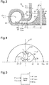
- the compressor 18, which compresses air supplied to the engine 10, will now be described with reference to Figs. 3 and 4 .
- the compressor 18 includes a housing 31 and an impeller 32 accommodated in the housing 31.
- the impeller 32 compresses air by rotating together with the coupling shaft 21.
- the housing 31 includes an inlet 33 through which air prior to being compressed by the impeller 32 flows, a diffuser 35 into which the air compressed by rotation of the impeller 32 flows, and a scroll 36 into which air flows through an outlet surface 35a of the diffuser 35.
- the impeller 32 includes a hub 37 that rotates together with the coupling shaft 21 and blades 38 formed integrally with the hub 37.
- the hub 37 has an outer circumferential surface 37a inclined toward the outer side of the impeller 32 in the radial direction.
- Each blade 38 has a radially inner end, which is located close to the central axis of the impeller 32 and away from the central axis by an inner diameter r1. Further, each blade 38 has a radially outer end, which is located on the opposite side from the central axis of the impeller 32 and away from the central axis by an outer diameter r2.
- the intake system model 7, which is an element of the state quantity estimating device 6, will now be described in further detail with reference to Figs. 5 and 6 .
- the intake system model 7 includes the inlet pressure Pin and the inlet temperature Tin as input values and includes the compression temperature Tcmp, the compression pressure Pcmp, and the intake air amount Ga as output values. Further, the intake system model 7 uses the output values of the compression temperature Tcmp, the compression pressure Pcmp, and the intake air amount Ga as previous values to calculate the subsequent compression temperature Tcmp, the subsequent compression pressure Pcmp, and the subsequent intake air amount Ga. In the intake system model 7, suitable initial values are given to the state quantities related to the calculation as needed.
- the intake system model 7 includes various types of functional units.
- the compressor driving torque ⁇ cmp is calculated by dividing an output Wcmp of the compressor 18 by the previous value of the turbo rotational speed Ntrb.
- the output Wcmp of the compressor 18 is calculated by, for example, substituting, into equation (2), the previous value of an adiabatic compression efficiency ⁇ cmp, an air heat capacity ratio ⁇ of air, the inlet pressure Pin, the previous value of the compression pressure Pcmp, the previous value of the intake air amount Ga, a gas constant R, and the inlet temperature Tin.
- the compressor driving torque ⁇ cmp may be calculated in the intake system model 7. Alternatively, calculation values of the compressor driving torque ⁇ cmp may be obtained using other models and input to the intake system model 7.
- W cmp 1 ⁇ cmp ⁇ ⁇ ⁇ 1 P cmp P in ⁇ ⁇ 1 ⁇ ⁇ 1 G a RT in
- the turbine driving torque ⁇ trb is calculated by dividing an output Wtrb of the turbine 22, which is based on a turbine efficiency ⁇ trb, by the previous value of the turbo rotational speed Ntrb.
- the output Wtrb of the turbine 22 is calculated by, for example, substituting, into equation (3), the turbine efficiency ⁇ trb, the heat capacity ratio ⁇ of exhaust gas, the turbine upstream pressure Pexm, the turbine downstream pressure Pexh, the turbine upstream temperature Texm, an exhaust gas flow rate Gexh, and the gas constant R.
- a value of the turbine driving torque ⁇ trb may be obtained using the exhaust system model 9 and input to the intake system model 7.
- the turbine driving torque ⁇ trb may be calculated in the intake system model 7 when necessary state quantities are input to the intake system model 7.
- W trb ⁇ trb ⁇ ⁇ ⁇ 1 P exm P exh ⁇ ⁇ 1 ⁇ ⁇ 1 G exh RT exm
- An impeller outer diameter circumferential speed calculator 52 calculates the impeller outer diameter circumferential speed u2 based on the outer diameter r2 of the impeller 32 and the angular speed ⁇ of the impeller 32, which is based on the turbo rotational speed Ntrb.
- An impeller outlet flow speed calculator 53 calculates the impeller outlet flow speed c2, which is the flow speed of air flowing from the impeller 32 into the diffuser 35.
- the impeller outlet flow speed calculator 53 calculates, as the impeller outlet flow speed c2, a component of the impeller outer diameter circumferential speed u2 in a direction orthogonal to the radially outer end of each blade 38 at the outlet angle ⁇ .
- a total enthalpy calculator 54 calculates a total enthalpy H of air flowing into the diffuser 35.
- the total enthalpy H is energy given from the impeller 32 when air per unit mass flows from the inlet 33 into the diffuser 35.
- the total enthalpy H is the sum total of kinetic energy, internal energy, and pressure energy.
- the total enthalpy calculator 54 calculates the total enthalpy H using an empirical formula obtained from the results of experiments and simulations that have been conducted in advance for the compressor 18, which is a quadratic approximation in which the impeller outlet flow speed c2 is used as a variable.
- An intake volume amount calculator 55 converts the previous value of the intake air amount Ga into an intake volume amount Qa, which is a volume flow rate, using the previous value of the compression pressure Pcmp and the previous value of the compression temperature Tcmp.
- a friction loss ratio calculator 56 calculates a friction loss ratio ⁇ fric, which is the ratio of post-friction energy to pre-friction energy, in relation to friction loss, which is the loss of energy resulting from friction of the impeller 32 and air that occurs when the air is compressed by the impeller 32.
- the friction loss ratio calculator 56 calculates the friction loss ratio ⁇ fric using an empirical formula obtained from the results of experiments and simulations that have been conducted in advance for the compressor 18, which is a linear approximation in which the intake volume amount Qa is used as a variable.
- An impeller inner diameter circumferential speed calculator 57 calculates the impeller inner diameter circumferential speed u1 based on the inner diameter r1 of the impeller 32 and the angular speed ⁇ of the impeller 32, which is based on the turbo rotational speed Ntrb.
- a non-collision flow rate calculator 58 calculates a non-collision flow rate Qs, which is the volume flow rate of air flowing into the diffuser 35 without colliding with the impeller 32 in the air compressed by the impeller 32.
- the non-collision flow rate calculator 58 calculates the non-collision flow rate Qs using an empirical formula obtained based on the results of experiments and simulations that have been conducted in advance for the compressor 18, which is a quadratic approximation in which the impeller inner diameter circumferential speed u1 is used as a variable.
- a collision loss ratio calculator 59 calculates a collision loss ratio ⁇ imp, which is the ratio of post-collision energy to pre-collision energy, in relation to the loss of energy resulting from collision of air with the impeller 32.
- An adiabatic compression efficiency calculator 60 calculates, as the adiabatic compression efficiency ⁇ cmp in the compressor 18, a value obtained by multiplying the friction loss ratio ⁇ fric by the collision loss ratio ⁇ imp.
- a diffuser outlet flow speed calculator 61 calculates a diffuser outlet flow speed c3 by dividing, by the effective open area A of the outlet surface 35a, the intake volume amount Qa, which is calculated by the intake volume amount calculator 55.
- the effective open area A is the area of a portion of the outlet surface 35a where air passes.
- a temperature-pressure energy calculator 63 calculates, as a temperature-pressure energy htp, a value obtained by subtracting the kinetic energy hv from the total enthalpy H, that is, the sum of an internal energy ht and a pressure energy hp of the air in the outlet surface 35a.
- a pressure energy calculator 64 calculates the pressure energy hp of air in the outlet surface 35a.
- the pressure energy calculator 64 calculates the pressure energy hp by substituting the heat capacity ratio ⁇ of the air, the temperature-pressure energy htp, and the adiabatic compression efficiency ⁇ cmp into the following equation (4).
- h p ⁇ cmp h tp ⁇ cmp + 1
- Equation (4) is derived from the fact that the internal energy ht, the pressure energy hp, and the adiabatic compression efficiency ⁇ cmp are generally expressed by the following equations (5), (6), and (7), respectively, in the compressor 18.
- An internal energy calculator 65 calculates the internal energy ht by subtracting the pressure energy hp from the temperature-pressure energy htp.
- a compression temperature calculator 66 calculates the compression temperature Tcmp by substituting the internal energy ht, the heat capacity ratio ⁇ of air, the gas constant R, and the inlet temperature Tin into the following equation (8), which is obtained from equation (5).
- T cmp h t ⁇ ⁇ 1 R + T in
- a compression pressure calculator 67 calculates the compression pressure Pcmp by substituting the inlet pressure Pin, the pressure energy hp, the heat capacity ratio ⁇ of air, the gas constant R, and the inlet temperature Tin into the following equation (9), which is obtained from equation (6).
- P cmp P in h p ⁇ ⁇ 1 ⁇ RT in + 1 ⁇ ⁇ ⁇ 1
- An outlet pressure calculator 68 calculates the outlet pressure Pout, which is the pressure of air in the scroll 36.
- the outlet pressure calculator 68 calculates mass M of air in the intercooler 19 by cumulating the difference between an inflow amount Gcin of air that flows into the intercooler 19 and an outflow amount Gout of air that flows out of the intercooler 19.
- the outlet pressure calculator 68 calculates density ⁇ of air in the intercooler 19 by dividing the mass M by volume V of the intercooler 19 and calculates the intercooler inlet pressure Pcin at the inlet of the intercooler 19 based on the density ⁇ . Further, the outlet pressure calculator 68 calculates the outlet pressure Pout through mass conservation of volume elements from the scroll 36 to the intercooler 19.
- An intake air amount calculator 69 calculates the intake air amount Ga, which is the mass flow rate of air passing through the outlet surface 35a.
- the intake air amount calculator 69 calculates the intake air amount Ga by substituting the effective open area A of the outlet surface 35a, the heat capacity ratio ⁇ of air, the gas constant R, the compression temperature Tcmp, the compression pressure Pcmp, and the outlet pressure Pout into the following equation (10).
- G a A 2 ⁇ P cmp 2 ⁇ ⁇ 1 RT cmp P out P cmp 2 ⁇ ⁇ P out P cmp ⁇ + 1 ⁇
- air in the inlet 33 receives energy by an amount corresponding to the total enthalpy H from the impeller 32 until the air flows into the diffuser 35.
- the total enthalpy H is converted into the kinetic energy hv, the internal energy ht, and the pressure energy hp in the outlet surface 35a of the diffuser 35 based on the diffuser outlet flow speed c3 and the adiabatic compression efficiency ⁇ cmp.
- the compression temperature Temp is calculated based on the internal energy ht and the inlet temperature Tin.
- the compression pressure Pcmp is calculated based on the pressure energy hp, the inlet pressure Pin, and the inlet temperature Tin.
- the intake air amount Ga which is the mass flow rate of air passing through the outlet surface 35a, is calculated by substituting the compression temperature Temp and the compression pressure Pcmp into equation (10).
- the state quantity estimating device has the following advantages.
- the impeller outlet flow speed c2 may be calculated in the following manner. That is, for example, a gradient of the impeller outlet flow speed corresponding to the turbo rotational speed Ntrb is set between the radially outer ends of two blades 38. Further, the impeller outlet flow speed at the radially outer end of one of the two blades 38 is set to the impeller outlet flow speed c2 of the above-described embodiment, and the impeller outlet flow speed of the radially outer end of the other one of the two blades 38 is set to zero. In such a condition, a velocity distribution between the two blades 38 may be obtained so that the average value calculated from the velocity distribution is set to the impeller outlet flow speed c2.
- the diffuser outlet flow speed c3 does not have to be calculated by dividing the intake volume amount Qa, into which the previous value of the intake air amount Ga has been converted, by the effective open area A. Instead, the diffuser outlet flow speed c3 may be calculated using other methods.
- the adiabatic compression efficiency ⁇ cmp may be calculated by substituting the previous value of the compression pressure Pcmp and the previous value of the compression temperature Tcmp into equation (7).
- the adiabatic compression efficiency ⁇ cmp may be the average value of the calculation result of the adiabatic compression efficiency calculator 60 and the calculation result of equation (7).
- the internal energy calculator 65 does not have to calculate the internal energy ht by subtracting the pressure energy hp from the temperature-pressure energy htp. Instead, the internal energy calculator 65 may calculate the internal energy ht based on the temperature-pressure energy htp and the adiabatic compression efficiency ⁇ cmp.
- the state quantity estimating device 6 simply needs to include the intake system model 7, which estimates the state quantity of air compressed by the compressor 18, and does not have to include the engine model 8 or the like.
- the state quantity estimating device 6 does not have to obtain the turbo rotational speed Ntrb based on the angular speed ⁇ , which is obtained by cumulating the angular acceleration ⁇ , which is calculated from the compressor driving torque ⁇ cmp, the turbine driving torque ⁇ trb, and the inertia moment I. Instead, when installed in a vehicle, the state quantity estimating device 6 may obtain the turbo rotational speed Ntrb based on, for example, a detection value of a sensor that detects the rotational speed of the coupling shaft 21.
- the state quantity estimating device 6 does not have to obtain the outlet pressure Pout based on the intercooler inlet pressure Pcin. Instead, when installed in a vehicle, the state quantity estimating device 6 may obtain the outlet pressure Pout based on, for example, a detection value of a sensor that detects the outlet pressure Pout.
- the state quantity estimating device 6 which calculates the compression temperature Tcmp and the intake air amount Ga, may be used for on-board diagnostics (OBD) for a boost pressure sensor that detects the boost pressure Pb.
- OBD on-board diagnostics
- An estimation value of the boost pressure Pb may be calculated as follows.
- the state quantity estimating device 6 calculates an EGR gas inflow amount, which is the flow rate of EGR gas flowing into the intake passage 16, and an EGR gas inflow temperature, which is the temperature of EGR gas flowing into the intake passage 16, in addition to the intake air amount Ga and the compression temperature Tcmp. Further, the state quantity estimating device 6 calculates a working gas amount, which is the flow rate of working gas, and a working gas temperature, which is the temperature of working gas. The state quantity estimating device 6 can calculate an estimation value of the boost pressure Pb by integrating, by mass and energy, the intake air amount Ga, the compression temperature Tcmp, the EGR gas inflow amount, the EGR gas inflow temperature, the working gas amount, and the working gas temperature.
Landscapes
- Engineering & Computer Science (AREA)
- Mechanical Engineering (AREA)
- General Engineering & Computer Science (AREA)
- Chemical & Material Sciences (AREA)
- Combustion & Propulsion (AREA)
- Physics & Mathematics (AREA)
- General Physics & Mathematics (AREA)
- Supercharger (AREA)
- Combined Controls Of Internal Combustion Engines (AREA)
- Control Of Positive-Displacement Air Blowers (AREA)
- Structures Of Non-Positive Displacement Pumps (AREA)
Abstract
This state quantity estimating device is configured to: calculate a total enthalpy, which is the energy imparted to air by an impeller, an adiabatic compression efficiency of a compressor, and a diffuser outlet flow velocity, which is the flow velocity of air at an outlet surface of a diffuser; allocate to internal energy and pressure energy, on the basis of the adiabatic compression efficiency, a value obtained by subtracting kinetic energy based on the diffuser outlet flow velocity from the total enthalpy; calculate a compression temperature, which is the temperature of air flowing into the outlet surface, by means of a calculation formula including as variables the internal energy and an inlet temperature which is the temperature of the air prior to compression by the impeller; and calculate a compression pressure, which is the pressure of air flowing into the outlet surface, by means of a calculation formula including as variables the pressure energy and an inlet pressure which is the pressure of the air prior to compression by the impeller.
Description
- The present invention relates to a state quantity estimating device that estimates the state quantity of air compressed by a compressor.
- An engine controller for controlling an engine calculates a control command value to a control subject based on a detection value of a sensor that detects the state quantities of running the engine. Then, the engine controller outputs the calculated control command value to the control subject. For example, the engine controller includes an intake air amount as one of the state quantities that are used to calculate a control command value to an injector that injects fuel.
- The development of control logic in such an engine controller is often based on a model-based development using a state quantity estimating device that calculates estimation values of various types of state quantities of running the engine. Patent Document 1 describes such an example. The engine controller of Patent Document 1 calculates a control command value using, as a detection value of a sensor, the estimation value of each state quantity calculated by the state quantity estimating device.
- Patent Document 1: Japanese Laid-Open Patent Publication No.
11-014507 - It is preferred that an estimation value calculated by the state quantity estimating device be highly accurate in order to enhance the accuracy of the control logic of the engine controller. Thus, the model-based development of the engine controller, which is installed in a vehicle including a compressor that compresses air drawn in by the engine, needs to have the estimation value of the state quantity of the compressed air.
- It is an objective of the present invention to provide a state quantity estimating device capable of estimating a state quantity of air compressed by a compressor with high accuracy.
- A state quantity estimating device that solves the above-described problem estimates a state quantity of air compressed by a compressor including an impeller that compresses air and a housing that accommodates the impeller. The housing includes a diffuser into which the air compressed by the impeller flows and a scroll into which the air flows through an outlet surface of the diffuser. The state quantity estimating device is configured to calculate a total enthalpy, which is energy based on an impeller outlet flow speed, which is a flow speed of air discharged by the impeller to the diffuser, and given to the air by the impeller, an adiabatic compression efficiency of the compressor, and a diffuser outlet flow speed, which is a flow speed of air in the outlet surface of the diffuser. The state quantity estimating device is also configured to allocate, to an internal energy and a pressure energy, a value obtained by subtracting a kinetic energy based on the diffuser outlet flow speed from the total enthalpy, based on the adiabatic compression efficiency. The state quantity estimating device is further configured to calculate a compression temperature, which is a temperature of air flowing into the outlet surface, using an operational equation that includes, as variables, the internal energy and an inlet temperature, which is a temperature of air prior to being compressed by the impeller, and calculate a compression pressure, which is pressure of the air flowing into the outlet surface, using an operational equation that includes, as variables, the pressure energy and an inlet pressure, which is pressure of the air prior to being compressed by the impeller.
-
-
Fig. 1 is a block diagram schematically showing an example of a model-based development using a state quantity estimating device according to an embodiment. -
Fig. 2 is a diagram showing the schematic configuration of an engine system for which the state quantity estimating device ofFig. 1 is employed. -
Fig. 3 is a cross-sectional view showing an example of the cross-sectional structure of the compressor in the engine system ofFig. 2 . -
Fig. 4 is a diagram schematically showing an example of the structure of the compressor in the engine system ofFig. 2 . -
Fig. 5 is a block diagram illustrating examples of input values and output values of the intake system model in the state quantity estimating device ofFig. 1 . -
Fig. 6 is a functional block diagram illustrating an example of the intake system model in the state quantity estimating device ofFig. 1 . - A state quantity estimating device according to an embodiment will now be described with reference to
Figs. 1 to 6 . First, the summary of a model-based development using the state quantity estimating device will be described with reference toFig. 1 . -
Fig. 1 shows a model-based development of an engine ECU 5. The model-based development is performed using the engine ECU 5, which is subject to development, and a state quantity estimating device 6. The state quantity estimating device 6 includes various types of models capable of simulating behaviors of actual devices. The state quantity estimating device 6 performs various types of simulations in which environmental conditions, such as the external temperature and the atmospheric pressure, and control command values from the engine ECU 5 are input values in order to output values necessary for calculating control command values by the engine ECU 5, such as an intake air amount. - In the model-based development of the engine ECU 5, which is installed in a vehicle including a turbocharger, the state quantity estimating device 6 includes, for example, an
intake system model 7, anengine model 8, and anexhaust system model 9. Theintake system model 7 calculates various types of state quantities that indicate the states of air drawn in by the engine through the intake passage, such as a state of air compressed by a compressor, a state of air flowing into an intercooler, and a state of air drawn in by the engine. In addition to the output torque of the engine, theengine model 8 calculates state quantities indicating, for example, a state of exhaust gas discharged to the exhaust manifold. Theexhaust system model 9 calculates various types of state quantities that indicate a state of exhaust gas discharged from the exhaust manifold through the exhaust passage into the ambient air, such as a state of exhaust gas flowing into the turbine and a state of exhaust gas flowing out of the turbine. - The state quantity estimating device 6 may be circuitry including 1) one or more dedicated hardware circuits such as an ASIC, 2) one or more processors running on computer programs (software), or 3) a combination of a hardware circuit and a processor. The processor includes a CPU and a memory such as a ROM or a RAM, which stores programs executed by the CPU. The memory, or computer readable medium, includes any type of medium that is accessible by a versatile computer or a dedicated computer.
- An example of an engine system including a turbocharger will now be described with reference to
Fig. 2 . - As shown in
Fig. 2 , the engine system includes anengine 10. Theengine 10 includes acylinder block 11 havingcylinders 12. To eachcylinder 12, an injector 13 injects fuel. Anintake manifold 14 that supplies intake air to eachcylinder 12 and anexhaust manifold 15 into which exhaust gas flows from eachcylinder 12 are connected to thecylinder block 11. - An
intake passage 16 is connected to theintake manifold 14. Theintake passage 16 includes an air cleaner (not shown), acompressor 18, which is an element of aturbocharger 17, and anintercooler 19 sequentially from the upstream side. Anexhaust passage 20 is connected to theexhaust manifold 15. Theexhaust passage 20 includes aturbine 22 coupled to thecompressor 18 by acoupling shaft 21. Theturbine 22 is an element of theturbocharger 17. - The engine system includes an
EGR device 23. The EGRdevice 23 includes an EGRpassage 25 that connects theexhaust manifold 15 to theintake passage 16. The EGRpassage 25 includes a water-cooledEGR cooler 26. AnEGR valve 27 is arranged on a side of the EGRcooler 26 close to theintake passage 16. When theEGR valve 27 is open, some of exhaust gas is drawn into theintake passage 16 as EGR gas. That is, thecylinders 12 are supplied with the mixture of air and EGR gas as working gas when theEGR valve 27 is open, and thecylinders 12 are supplied with only air as working gas when theEGR valve 27 is closed. - In such an engine system, the
cylinders 12 are supplied with, as working gas or some of working gas, air that has been compressed by theturbocharger 17 and then cooled by theintercooler 19. Further, in thecylinders 12, an air-fuel mixture is generated when fuel is injected from the injector 13, and exhaust gas is generated when the mixture burns. The exhaust gas is discharged to theexhaust manifold 15 and then flows into theexhaust passage 20. Further, the exhaust gas drives theturbine 22 and is then discharged into the ambient air. - The quantity symbols shown in
Fig. 2 are defined as follows. - Pexm: turbine upstream pressure Pexm, which is the pressure of exhaust gas flowing into the
turbine 22 - Texm: turbine upstream temperature Texm, which is the temperature of exhaust gas flowing into the
turbine 22 - Pexh: turbine downstream pressure Pexh, which is the pressure of exhaust gas that has passed through the
turbine 22 - Pcin: intercooler inlet pressure Pcin, which is the pressure of air flowing into the
intercooler 19 - Pb: boost pressure Pb, which is the pressure of working gas on the downstream side of where the
intake passage 16 is connected to theEGR passage 25 - The
compressor 18, which compresses air supplied to theengine 10, will now be described with reference toFigs. 3 and 4 . - As shown in
Figs. 3 and 4 , thecompressor 18 includes ahousing 31 and animpeller 32 accommodated in thehousing 31. Theimpeller 32 compresses air by rotating together with thecoupling shaft 21. Thehousing 31 includes aninlet 33 through which air prior to being compressed by theimpeller 32 flows, adiffuser 35 into which the air compressed by rotation of theimpeller 32 flows, and ascroll 36 into which air flows through anoutlet surface 35a of thediffuser 35. Theimpeller 32 includes ahub 37 that rotates together with thecoupling shaft 21 andblades 38 formed integrally with thehub 37. Thehub 37 has an outer circumferential surface 37a inclined toward the outer side of theimpeller 32 in the radial direction. Eachblade 38 has a radially inner end, which is located close to the central axis of theimpeller 32 and away from the central axis by an inner diameter r1. Further, eachblade 38 has a radially outer end, which is located on the opposite side from the central axis of theimpeller 32 and away from the central axis by an outer diameter r2. - In the
compressor 18, when rotation of theimpeller 32 about thecoupling shaft 21 produces energy and the energy is given to air in theinlet 33, the air is compressed to flow into thediffuser 35. Then, the air flows into thescroll 36 through theoutlet surface 35a of thediffuser 35. The air that has flowed into thescroll 36 flows into theintake passage 16, which is located downstream of thecompressor 18. The air then flows through theintake passage 16 toward theintercooler 19. - The quantity symbols shown in
Fig. 3 are defined as follows. - Pin: inlet pressure Pin, which is the pressure of air in the
inlet 33 - Tin: inlet temperature Tin, which is the temperature of air in the
inlet 33 - Pcmp: compression pressure Pcmp, which is the pressure of air immediately prior to flowing into the
outlet surface 35a - Tcmp: compression temperature Tcmp, which is the temperature of air immediately prior to flowing into the
outlet surface 35a - Pout: outlet pressure Pout, which is the pressure of air in the
scroll 36 - Tout: outlet temperature Tout, which is the temperature of air in the
scroll 36 - A: effective open area A of the
outlet surface 35a - Ga: intake air amount Ga, which is the mass flow rate of air passing through the
outlet surface 35a per unit of time - Further, the quantity symbols shown in
Fig. 4 are defined as follows. - u1: impeller inner diameter circumferential speed u1, which is the circumferential speed at the radially inner end of each
blade 38 - u2: impeller outer diameter circumferential speed u2, which is the circumferential speed at the radially outer end of each
blade 38 - θ: outlet angle θ of each
blade 38 - c2: impeller outlet flow speed c2, which is the flow speed of air discharged by the
impeller 32 - c3: diffuser outlet flow speed c3, which is the flow speed of air passing through the
outlet surface 35a - The
intake system model 7, which is an element of the state quantity estimating device 6, will now be described in further detail with reference toFigs. 5 and6 . - As shown in
Fig. 5 , theintake system model 7 includes the inlet pressure Pin and the inlet temperature Tin as input values and includes the compression temperature Tcmp, the compression pressure Pcmp, and the intake air amount Ga as output values. Further, theintake system model 7 uses the output values of the compression temperature Tcmp, the compression pressure Pcmp, and the intake air amount Ga as previous values to calculate the subsequent compression temperature Tcmp, the subsequent compression pressure Pcmp, and the subsequent intake air amount Ga. In theintake system model 7, suitable initial values are given to the state quantities related to the calculation as needed. - As shown in
Fig. 6 , theintake system model 7 includes various types of functional units. - A turbo
rotational speed calculator 51 calculates a turbo rotational speed Ntrb, which is the rotational speed of thecoupling shaft 21, that is, the rotational speed of theimpeller 32. As shown in equation (1), the turborotational speed calculator 51 calculates an angular acceleration α by dividing, by an inertia moment I of a rotor configured by thecoupling shaft 21 and theimpeller 32, a value obtained by subtracting a compressor driving torque τcmp from a turbine driving torque τtrb. Further, the turborotational speed calculator 51 calculates the turbo rotational speed Ntrb based on an angular speed ω, which is obtained by cumulating the angular acceleration α.
- The compressor driving torque τcmp is calculated by dividing an output Wcmp of the
compressor 18 by the previous value of the turbo rotational speed Ntrb. The output Wcmp of thecompressor 18 is calculated by, for example, substituting, into equation (2), the previous value of an adiabatic compression efficiency ηcmp, an air heat capacity ratio κ of air, the inlet pressure Pin, the previous value of the compression pressure Pcmp, the previous value of the intake air amount Ga, a gas constant R, and the inlet temperature Tin. The compressor driving torque τcmp may be calculated in theintake system model 7. Alternatively, calculation values of the compressor driving torque τcmp may be obtained using other models and input to theintake system model 7.
- The turbine driving torque τtrb is calculated by dividing an output Wtrb of the
turbine 22, which is based on a turbine efficiency ηtrb, by the previous value of the turbo rotational speed Ntrb. The output Wtrb of theturbine 22 is calculated by, for example, substituting, into equation (3), the turbine efficiency ηtrb, the heat capacity ratio κ of exhaust gas, the turbine upstream pressure Pexm, the turbine downstream pressure Pexh, the turbine upstream temperature Texm, an exhaust gas flow rate Gexh, and the gas constant R. A value of the turbine driving torque τtrb may be obtained using theexhaust system model 9 and input to theintake system model 7. Alternatively, the turbine driving torque τtrb may be calculated in theintake system model 7 when necessary state quantities are input to theintake system model 7.
- An impeller outer diameter
circumferential speed calculator 52 calculates the impeller outer diameter circumferential speed u2 based on the outer diameter r2 of theimpeller 32 and the angular speed ω of theimpeller 32, which is based on the turbo rotational speed Ntrb. - An impeller outlet
flow speed calculator 53 calculates the impeller outlet flow speed c2, which is the flow speed of air flowing from theimpeller 32 into thediffuser 35. The impeller outletflow speed calculator 53 calculates, as the impeller outlet flow speed c2, a component of the impeller outer diameter circumferential speed u2 in a direction orthogonal to the radially outer end of eachblade 38 at the outlet angle θ. - A
total enthalpy calculator 54 calculates a total enthalpy H of air flowing into thediffuser 35. The total enthalpy H is energy given from theimpeller 32 when air per unit mass flows from theinlet 33 into thediffuser 35. In detail, the total enthalpy H is the sum total of kinetic energy, internal energy, and pressure energy. Thetotal enthalpy calculator 54 calculates the total enthalpy H using an empirical formula obtained from the results of experiments and simulations that have been conducted in advance for thecompressor 18, which is a quadratic approximation in which the impeller outlet flow speed c2 is used as a variable. - An intake
volume amount calculator 55 converts the previous value of the intake air amount Ga into an intake volume amount Qa, which is a volume flow rate, using the previous value of the compression pressure Pcmp and the previous value of the compression temperature Tcmp. - A friction
loss ratio calculator 56 calculates a friction loss ratio ηfric, which is the ratio of post-friction energy to pre-friction energy, in relation to friction loss, which is the loss of energy resulting from friction of theimpeller 32 and air that occurs when the air is compressed by theimpeller 32. The frictionloss ratio calculator 56 calculates the friction loss ratio ηfric using an empirical formula obtained from the results of experiments and simulations that have been conducted in advance for thecompressor 18, which is a linear approximation in which the intake volume amount Qa is used as a variable. - An impeller inner diameter
circumferential speed calculator 57 calculates the impeller inner diameter circumferential speed u1 based on the inner diameter r1 of theimpeller 32 and the angular speed ω of theimpeller 32, which is based on the turbo rotational speed Ntrb. - A non-collision
flow rate calculator 58 calculates a non-collision flow rate Qs, which is the volume flow rate of air flowing into thediffuser 35 without colliding with theimpeller 32 in the air compressed by theimpeller 32. The non-collisionflow rate calculator 58 calculates the non-collision flow rate Qs using an empirical formula obtained based on the results of experiments and simulations that have been conducted in advance for thecompressor 18, which is a quadratic approximation in which the impeller inner diameter circumferential speed u1 is used as a variable. - A collision
loss ratio calculator 59 calculates a collision loss ratio ηimp, which is the ratio of post-collision energy to pre-collision energy, in relation to the loss of energy resulting from collision of air with theimpeller 32. The collisionloss ratio calculator 59 calculates the collision loss ratio ηimp using an empirical formula obtained based on the results of experiments and simulations that have been conducted in advance for thecompressor 18, which is a quadratic approximation in which the collision flow rate Qimp (Qimp = Qa - Qs) is used as a variable. - An adiabatic
compression efficiency calculator 60 calculates, as the adiabatic compression efficiency ηcmp in thecompressor 18, a value obtained by multiplying the friction loss ratio ηfric by the collision loss ratio ηimp. - A diffuser outlet
flow speed calculator 61 calculates a diffuser outlet flow speed c3 by dividing, by the effective open area A of theoutlet surface 35a, the intake volume amount Qa, which is calculated by the intakevolume amount calculator 55. The effective open area A is the area of a portion of theoutlet surface 35a where air passes. - A
kinetic energy calculator 62 calculates a kinetic energy hv (hv = 1/2 × c3^2) of air in theoutlet surface 35a of thediffuser 35 based on the diffuser outlet flow speed c3. - A temperature-
pressure energy calculator 63 calculates, as a temperature-pressure energy htp, a value obtained by subtracting the kinetic energy hv from the total enthalpy H, that is, the sum of an internal energy ht and a pressure energy hp of the air in theoutlet surface 35a. - A
pressure energy calculator 64 calculates the pressure energy hp of air in theoutlet surface 35a. Thepressure energy calculator 64 calculates the pressure energy hp by substituting the heat capacity ratio κ of the air, the temperature-pressure energy htp, and the adiabatic compression efficiency ηcmp into the following equation (4).
- Equation (4) is derived from the fact that the internal energy ht, the pressure energy hp, and the adiabatic compression efficiency ηcmp are generally expressed by the following equations (5), (6), and (7), respectively, in the
compressor 18.


- An
internal energy calculator 65 calculates the internal energy ht by subtracting the pressure energy hp from the temperature-pressure energy htp. - A
compression temperature calculator 66 calculates the compression temperature Tcmp by substituting the internal energy ht, the heat capacity ratio κ of air, the gas constant R, and the inlet temperature Tin into the following equation (8), which is obtained from equation (5).
- A
compression pressure calculator 67 calculates the compression pressure Pcmp by substituting the inlet pressure Pin, the pressure energy hp, the heat capacity ratio κ of air, the gas constant R, and the inlet temperature Tin into the following equation (9), which is obtained from equation (6).
- An
outlet pressure calculator 68 calculates the outlet pressure Pout, which is the pressure of air in thescroll 36. Theoutlet pressure calculator 68 calculates mass M of air in theintercooler 19 by cumulating the difference between an inflow amount Gcin of air that flows into theintercooler 19 and an outflow amount Gout of air that flows out of theintercooler 19. Theoutlet pressure calculator 68 calculates density ρ of air in theintercooler 19 by dividing the mass M by volume V of theintercooler 19 and calculates the intercooler inlet pressure Pcin at the inlet of theintercooler 19 based on the density ρ. Further, theoutlet pressure calculator 68 calculates the outlet pressure Pout through mass conservation of volume elements from thescroll 36 to theintercooler 19. - An intake
air amount calculator 69 calculates the intake air amount Ga, which is the mass flow rate of air passing through theoutlet surface 35a. The intakeair amount calculator 69 calculates the intake air amount Ga by substituting the effective open area A of theoutlet surface 35a, the heat capacity ratio κ of air, the gas constant R, the compression temperature Tcmp, the compression pressure Pcmp, and the outlet pressure Pout into the following equation (10).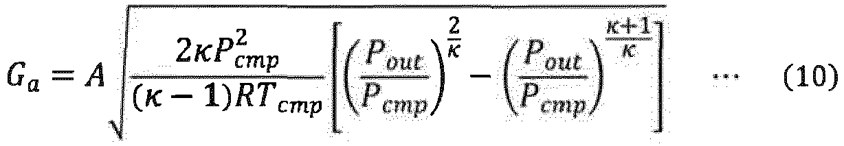
- In the state quantity estimating device 6, which includes the
intake system model 7 with the above-described configuration, air in theinlet 33 receives energy by an amount corresponding to the total enthalpy H from theimpeller 32 until the air flows into thediffuser 35. The total enthalpy H is converted into the kinetic energy hv, the internal energy ht, and the pressure energy hp in theoutlet surface 35a of thediffuser 35 based on the diffuser outlet flow speed c3 and the adiabatic compression efficiency ηcmp. Then, the compression temperature Temp is calculated based on the internal energy ht and the inlet temperature Tin. Further, the compression pressure Pcmp is calculated based on the pressure energy hp, the inlet pressure Pin, and the inlet temperature Tin. Furthermore, the intake air amount Ga, which is the mass flow rate of air passing through theoutlet surface 35a, is calculated by substituting the compression temperature Temp and the compression pressure Pcmp into equation (10). - The state quantity estimating device according to the above-described embodiment has the following advantages.
- (1) In the
intake system model 7, energy given by theimpeller 32 is converted into various types of energy. More specifically, the energy given by theimpeller 32 to air in theinlet 33 having the inlet temperature Tin and the inlet pressure Pin is set as the total enthalpy H, and the total enthalpy H is converted into the kinetic energy hv, the internal energy ht, and the pressure energy hp. Then, the compression temperature Tcmp and the compression pressure Pcmp are calculated based on the values of the converted energy. This enhances the accuracy of the calculation results of the compression temperature Tcmp and the compression pressure Pcmp. Further, calculating the intake air amount Ga using the compression temperature Tcmp and the compression pressure Pcmp enhances the accuracy of the intake air amount Ga.
There is a familiar method for calculating the intake air amount Ga and the compression temperature Tcmp using maps obtained from the results of experiments and simulations conducted in advance for thecompressor 18. In such a calculation method, the intake air amount Ga is calculated using, for example, a map in which the turbo rotational speed Ntrb and a compression ratio πcmp(πcmp = Pout/Pin) in thecompressor 18 are used as variables. Further, the compression temperature Tcmp is calculated using, for example, the adiabatic compression efficiency ηcmp, which is obtained from a map in which the compression ratio πcmp and the intake air amount Ga are used as variables. However, in such a calculation method, the intake air amount Ga and the compression temperature Tcmp are unambiguously calculated in accordance with different states. Thus, interaction of the intake air amount Ga and the compression temperature Tcmp is not sufficiently taken into account. Accordingly, reproducibility may be low in the vicinity of the inflection point of each state quantity such as the turbo rotational speed Ntrb, thereby lowering the accuracy of the calculation result. Further, since two maps are used to represent the characteristics of one compressor, modification of one of the maps for system identification may not be reflected on the other one of the maps. As a result, modification may be performed differently from an actual device.
In the above-described configuration, the total enthalpy H is calculated based on the previous value of each state quantity, and the total enthalpy H is converted into the kinetic energy hv, the internal energy ht, and the pressure energy hp. That is, the intake air amount Ga, the compression pressure Pcmp, and the compression temperature Tcmp at a point in time are calculated taking into account various state quantities at the previous point in time such as the turbo rotational speed Ntrb, the intake air amount Ga, the compression pressure Pcmp, and the compression temperature Tcmp. Thus, since the previous values and interaction of the state quantities are taken into account, the calculation results of the intake air amount Ga, the compression pressure Pcmp, and the compression temperature Tcmp improve reproducibility in the vicinity of the inflection point of each state quantity. This enhances the accuracy of the calculation result of each state quantity. - (2) In the
intake system model 7, the adiabatic compression efficiency ηcmp is calculated by multiplying the friction loss ratio ηfric by the collision loss ratio ηimp. The friction loss ratio ηfric is calculated using a linear equation that includes, as a variable, the intake volume amount Qa, into which the previous value of the intake air amount Ga has been converted using the previous value of the compression temperature Tcmp and the previous value of the compression pressure Pcmp. Further, the collision loss ratio ηimp is calculated using a quadratic equation that includes, as a variable, the collision flow rate Qimp, which is obtained by subtracting the non-collision flow rate Qs from the intake volume amount Qa. The non-collision flow rate Qs is calculated using a quadratic equation that includes, as a variable, the impeller inner diameter circumferential speed u1 based on the turbo rotational speed Ntrb.
Such a configuration reduces the load on the state quantity estimating device 6 in relation to the calculation of the friction loss ratio ηfric and the collision loss ratio ηimp. This increases the speed of calculating the compression temperature Tcmp, the compression pressure Pcmp, and the intake air amount Ga. In addition, the friction loss ratio ηfric and the collision loss ratio ηimp are calculated independently from each other. Thus, when the model of calculating the adiabatic compression efficiency ηcmp is formulated, adjustment can be easily performed. - (3) In the
intake system model 7, the diffuser outlet flow speed c3 is calculated by dividing the intake volume amount Qa by the effective open area A. This configuration reduces the load on the state quantity estimating device 6 in relation to the calculation of the diffuser outlet flow speed c3. - (4) In the
intake system model 7, the impeller outlet flow speed c2 is calculated based on the outer diameter r2 of theimpeller 32, the outlet angle θ of eachblade 38, and the angular speed ω of theimpeller 32, which is based on the turbo rotational speed Ntrb. This configuration reduces the load on the state quantity estimating device 6 in relation to the calculation of the impeller outlet flow speed c2. - The above-described embodiment may be modified as follows.
- The impeller outlet flow speed c2 may be calculated in the following manner. That is, for example, a gradient of the impeller outlet flow speed corresponding to the turbo rotational speed Ntrb is set between the radially outer ends of two
blades 38. Further, the impeller outlet flow speed at the radially outer end of one of the twoblades 38 is set to the impeller outlet flow speed c2 of the above-described embodiment, and the impeller outlet flow speed of the radially outer end of the other one of the twoblades 38 is set to zero. In such a condition, a velocity distribution between the twoblades 38 may be obtained so that the average value calculated from the velocity distribution is set to the impeller outlet flow speed c2. - The diffuser outlet flow speed c3 does not have to be calculated by dividing the intake volume amount Qa, into which the previous value of the intake air amount Ga has been converted, by the effective open area A. Instead, the diffuser outlet flow speed c3 may be calculated using other methods.
- The adiabatic compression efficiency ηcmp may be calculated by substituting the previous value of the compression pressure Pcmp and the previous value of the compression temperature Tcmp into equation (7). Alternatively, the adiabatic compression efficiency ηcmp may be the average value of the calculation result of the adiabatic
compression efficiency calculator 60 and the calculation result of equation (7). - The
internal energy calculator 65 does not have to calculate the internal energy ht by subtracting the pressure energy hp from the temperature-pressure energy htp. Instead, theinternal energy calculator 65 may calculate the internal energy ht based on the temperature-pressure energy htp and the adiabatic compression efficiency ηcmp. - The state quantity estimating device 6 simply needs to include the
intake system model 7, which estimates the state quantity of air compressed by thecompressor 18, and does not have to include theengine model 8 or the like. - The state quantity estimating device 6 does not have to obtain the turbo rotational speed Ntrb based on the angular speed ω, which is obtained by cumulating the angular acceleration α, which is calculated from the compressor driving torque τcmp, the turbine driving torque τtrb, and the inertia moment I. Instead, when installed in a vehicle, the state quantity estimating device 6 may obtain the turbo rotational speed Ntrb based on, for example, a detection value of a sensor that detects the rotational speed of the
coupling shaft 21. - The state quantity estimating device 6 does not have to obtain the outlet pressure Pout based on the intercooler inlet pressure Pcin. Instead, when installed in a vehicle, the state quantity estimating device 6 may obtain the outlet pressure Pout based on, for example, a detection value of a sensor that detects the outlet pressure Pout.
- When installed in a vehicle, the state quantity estimating device 6, which calculates the compression temperature Tcmp and the intake air amount Ga, may be used for on-board diagnostics (OBD) for a boost pressure sensor that detects the boost pressure Pb. An estimation value of the boost pressure Pb may be calculated as follows.
- For example, the state quantity estimating device 6 calculates an EGR gas inflow amount, which is the flow rate of EGR gas flowing into the
intake passage 16, and an EGR gas inflow temperature, which is the temperature of EGR gas flowing into theintake passage 16, in addition to the intake air amount Ga and the compression temperature Tcmp. Further, the state quantity estimating device 6 calculates a working gas amount, which is the flow rate of working gas, and a working gas temperature, which is the temperature of working gas. The state quantity estimating device 6 can calculate an estimation value of the boost pressure Pb by integrating, by mass and energy, the intake air amount Ga, the compression temperature Tcmp, the EGR gas inflow amount, the EGR gas inflow temperature, the working gas amount, and the working gas temperature.
Claims (5)
- A state quantity estimating device that estimates a state quantity of air compressed by a compressor comprising an impeller that compresses air and a housing that accommodates the impeller, the housing including a diffuser into which the air compressed by the impeller flows and a scroll into which the air flows through an outlet surface of the diffuser, wherein the state quantity estimating device is configured to:calculate a total enthalpy, which is energy based on an impeller outlet flow speed, which is a flow speed of air discharged by the impeller to the diffuser, and given to the air by the impeller, an adiabatic compression efficiency of the compressor, and a diffuser outlet flow speed, which is a flow speed of air in the outlet surface of the diffuser;allocate, to an internal energy and a pressure energy, a value obtained by subtracting a kinetic energy based on the diffuser outlet flow speed from the total enthalpy, based on the adiabatic compression efficiency; andcalculate a compression temperature, which is a temperature of air flowing into the outlet surface, using an operational equation that includes, as variables, the internal energy and an inlet temperature, which is a temperature of air prior to being compressed by the impeller, and calculate a compression pressure, which is pressure of the air flowing into the outlet surface, using an operational equation that includes, as variables, the pressure energy and an inlet pressure, which is pressure of the air prior to being compressed by the impeller.
- The state quantity estimating device according to claim 1, wherein the state quantity estimating device is configured to:calculate an outlet pressure, which is pressure of air in the scroll; andcalculate an intake air amount, which is a mass flow rate of air passing through the outlet surface, using an operational equation that includes the compression pressure, the compression temperature, and the outlet pressure as variables.
- The state quantity estimating device according to claim 2, wherein the state quantity estimating device is configured to:convert a previous value of the intake air amount into an intake volume amount, which is a volume flow rate, using a previous value of the compression temperature and a previous value of the compression pressure;calculate a friction loss ratio, which results from friction between the impeller and air, based on the intake volume amount and calculate a collision loss ratio, which results from collision of air with the impeller, based on a collision flow rate obtained by subtracting a non-collision flow rate, which is a volume flow rate of air flowing into the diffuser without colliding with the impeller, from the intake volume amount; andcalculate the adiabatic compression efficiency by multiplying the friction loss ratio by the collision loss ratio.
- The state quantity estimating device according to claim 2 or 3, wherein the state quantity estimating device is configured to:convert a previous value of the intake air amount into an intake volume amount, which is a volume flow rate, using a previous value of the compression temperature and a previous value of the compression pressure; andcalculate the diffuser outlet flow speed by dividing the intake volume amount by an effective open area of the outlet surface.
- The state quantity estimating device according to any one of claims 1 to 4, wherein the state quantity estimating device is configured to:calculate an impeller outlet circumferential speed, which is a circumferential speed at an radially outer end of a blade of the impeller, based on a rotational speed of the impeller and an outer diameter of the impeller; andcalculate, as the impeller outlet flow speed, a component of the impeller outlet circumferential speed in a direction orthogonal to an radially outer end of the blade based on an outlet angle at the radially outer end of the blade.
Applications Claiming Priority (2)
| Application Number | Priority Date | Filing Date | Title |
|---|---|---|---|
| JP2017026753A JP6751680B2 (en) | 2017-02-16 | 2017-02-16 | State quantity estimation device |
| PCT/JP2018/005220 WO2018151201A1 (en) | 2017-02-16 | 2018-02-15 | State quantity estimating device |
Publications (1)
| Publication Number | Publication Date |
|---|---|
| EP3584447A1 true EP3584447A1 (en) | 2019-12-25 |
Family
ID=63169414
Family Applications (1)
| Application Number | Title | Priority Date | Filing Date |
|---|---|---|---|
| EP18753903.6A Withdrawn EP3584447A1 (en) | 2017-02-16 | 2018-02-15 | State quantity estimating device |
Country Status (5)
| Country | Link |
|---|---|
| US (1) | US20200033229A1 (en) |
| EP (1) | EP3584447A1 (en) |
| JP (1) | JP6751680B2 (en) |
| CN (1) | CN110036206A (en) |
| WO (1) | WO2018151201A1 (en) |
Families Citing this family (3)
| Publication number | Priority date | Publication date | Assignee | Title |
|---|---|---|---|---|
| WO2019059935A1 (en) * | 2017-09-23 | 2019-03-28 | Volvo Truck Corporation | Method for measuring exhaust gas recirculation flow in an engine system, controlling emissions in an engine system, and an engine system |
| CN112834230B (en) * | 2021-01-21 | 2022-05-24 | 北京理工大学 | Wide-range turbocharger turbine performance test bench |
| CN115292946B (en) * | 2022-08-15 | 2023-09-05 | 中国航发沈阳发动机研究所 | High-pressure turbine efficiency evaluation method and device based on variable specific heat calculation |
Family Cites Families (6)
| Publication number | Priority date | Publication date | Assignee | Title |
|---|---|---|---|---|
| JPH1114507A (en) | 1997-06-19 | 1999-01-22 | Denso Corp | Vehicle simulation device |
| US6659729B2 (en) * | 2001-02-15 | 2003-12-09 | Mayekawa Mfg. Co., Ltd. | Screw compressor equipment for accommodating low compression ratio and pressure variation and the operation method thereof |
| US6487869B1 (en) * | 2001-11-06 | 2002-12-03 | Themo King Corporation | Compressor capacity control system |
| JP2005016352A (en) * | 2003-06-24 | 2005-01-20 | Sanden Corp | Compressor output calculation device and control device using the same |
| JP2007321687A (en) * | 2006-06-02 | 2007-12-13 | Denso Corp | Control device for internal combustion engine with turbocharger |
| JP4512617B2 (en) * | 2007-06-26 | 2010-07-28 | 日立オートモティブシステムズ株式会社 | Control device and method for internal combustion engine |
-
2017
- 2017-02-16 JP JP2017026753A patent/JP6751680B2/en active Active
-
2018
- 2018-02-15 WO PCT/JP2018/005220 patent/WO2018151201A1/en unknown
- 2018-02-15 CN CN201880004497.0A patent/CN110036206A/en active Pending
- 2018-02-15 US US16/483,630 patent/US20200033229A1/en not_active Abandoned
- 2018-02-15 EP EP18753903.6A patent/EP3584447A1/en not_active Withdrawn
Also Published As
| Publication number | Publication date |
|---|---|
| JP6751680B2 (en) | 2020-09-09 |
| WO2018151201A1 (en) | 2018-08-23 |
| JP2018131988A (en) | 2018-08-23 |
| CN110036206A (en) | 2019-07-19 |
| US20200033229A1 (en) | 2020-01-30 |
Similar Documents
| Publication | Publication Date | Title |
|---|---|---|
| US7668704B2 (en) | Apparatus and method for compressor and turbine performance simulation | |
| US9133792B2 (en) | Unit for estimating the rotational speed of a turbocharger and system and method for controlling an internal combustion engine with a turbocharger | |
| US7918129B2 (en) | Diagnostic systems for cooling systems for internal combustion engines | |
| CN103814203B (en) | Diagnostic method and system for the PWTN with two-stage turbine compressor | |
| EP3584447A1 (en) | State quantity estimating device | |
| US7681442B2 (en) | Throttle upstream pressure estimating apparatus and cylinder charged air quantity calculating apparatus for internal combustion engine | |
| US9879598B2 (en) | Diagnosis device | |
| US8677748B2 (en) | Fresh air flow estimation | |
| Martin et al. | Implementing turbomachinery physics into data map-based turbocharger models | |
| US9828902B2 (en) | Cooling control system for internal combustion engine | |
| CN109072772B (en) | Physics-based vehicle turbocharger control techniques | |
| US20210293193A1 (en) | System and method for estimating turbo speed of an engine | |
| EP2541015B1 (en) | Control device for internal combustion engine | |
| US20070266706A1 (en) | System and method for monitoring boost leak | |
| EP3029304A1 (en) | Exhaust system state detection device | |
| CN113530666B (en) | Method for regulating and controlling rotating speed of turbocharger | |
| DE102009020804B4 (en) | Diagnostic system for an air-cooled intercooler for internal combustion engines | |
| US20150345377A1 (en) | Turbine expansion ratio estimation for model-based boost control | |
| Pesiridis et al. | Integration of unsteady effects in the turbocharger design process | |
| US10801356B2 (en) | Method for modeling a compressor speed | |
| JP6453121B2 (en) | Control device for variable capacity turbocharger | |
| KR20200020948A (en) | How to control a supercharged internal combustion engine | |
| Togai et al. | A Reduced Order Turbo-Charging Model for Real Time Engine Torque Profile Control | |
| WO2016022142A1 (en) | Exhaust gas recirculation flow measurement |
Legal Events
| Date | Code | Title | Description |
|---|---|---|---|
| PUAI | Public reference made under article 153(3) epc to a published international application that has entered the european phase |
Free format text: ORIGINAL CODE: 0009012 |
|
| 17P | Request for examination filed |
Effective date: 20190521 |
|
| AK | Designated contracting states |
Kind code of ref document: A1 Designated state(s): AL AT BE BG CH CY CZ DE DK EE ES FI FR GB GR HR HU IE IS IT LI LT LU LV MC MK MT NL NO PL PT RO RS SE SI SK SM TR |
|
| AX | Request for extension of the european patent |
Extension state: BA ME |
|
| DAV | Request for validation of the european patent (deleted) | ||
| DAX | Request for extension of the european patent (deleted) | ||
| STAA | Information on the status of an ep patent application or granted ep patent |
Free format text: STATUS: THE APPLICATION IS DEEMED TO BE WITHDRAWN |
|
| 18D | Application deemed to be withdrawn |
Effective date: 20200901 |