EP3584394A1 - Hoop lock with anti-rotation features - Google Patents
Hoop lock with anti-rotation features Download PDFInfo
- Publication number
- EP3584394A1 EP3584394A1 EP19190222.0A EP19190222A EP3584394A1 EP 3584394 A1 EP3584394 A1 EP 3584394A1 EP 19190222 A EP19190222 A EP 19190222A EP 3584394 A1 EP3584394 A1 EP 3584394A1
- Authority
- EP
- European Patent Office
- Prior art keywords
- openings
- pair
- cross
- tip
- section
- Prior art date
- Legal status (The legal status is an assumption and is not a legal conclusion. Google has not performed a legal analysis and makes no representation as to the accuracy of the status listed.)
- Granted
Links
Images




Classifications
-
- E—FIXED CONSTRUCTIONS
- E05—LOCKS; KEYS; WINDOW OR DOOR FITTINGS; SAFES
- E05B—LOCKS; ACCESSORIES THEREFOR; HANDCUFFS
- E05B67/00—Padlocks; Details thereof
- E05B67/06—Shackles; Arrangement of the shackle
- E05B67/063—Padlocks with removable shackles
-
- E—FIXED CONSTRUCTIONS
- E05—LOCKS; KEYS; WINDOW OR DOOR FITTINGS; SAFES
- E05B—LOCKS; ACCESSORIES THEREFOR; HANDCUFFS
- E05B67/00—Padlocks; Details thereof
- E05B67/06—Shackles; Arrangement of the shackle
- E05B2067/066—Shackle extensions
-
- Y—GENERAL TAGGING OF NEW TECHNOLOGICAL DEVELOPMENTS; GENERAL TAGGING OF CROSS-SECTIONAL TECHNOLOGIES SPANNING OVER SEVERAL SECTIONS OF THE IPC; TECHNICAL SUBJECTS COVERED BY FORMER USPC CROSS-REFERENCE ART COLLECTIONS [XRACs] AND DIGESTS
- Y10—TECHNICAL SUBJECTS COVERED BY FORMER USPC
- Y10T—TECHNICAL SUBJECTS COVERED BY FORMER US CLASSIFICATION
- Y10T70/00—Locks
- Y10T70/40—Portable
- Y10T70/413—Padlocks
- Y10T70/437—Key-controlled
- Y10T70/446—Rigid shackle
- Y10T70/452—Sliding
- Y10T70/454—Removable
-
- Y—GENERAL TAGGING OF NEW TECHNOLOGICAL DEVELOPMENTS; GENERAL TAGGING OF CROSS-SECTIONAL TECHNOLOGIES SPANNING OVER SEVERAL SECTIONS OF THE IPC; TECHNICAL SUBJECTS COVERED BY FORMER USPC CROSS-REFERENCE ART COLLECTIONS [XRACs] AND DIGESTS
- Y10—TECHNICAL SUBJECTS COVERED BY FORMER USPC
- Y10T—TECHNICAL SUBJECTS COVERED BY FORMER US CLASSIFICATION
- Y10T70/00—Locks
- Y10T70/40—Portable
- Y10T70/413—Padlocks
- Y10T70/437—Key-controlled
- Y10T70/446—Rigid shackle
- Y10T70/452—Sliding
- Y10T70/459—Both legs engaged
-
- Y—GENERAL TAGGING OF NEW TECHNOLOGICAL DEVELOPMENTS; GENERAL TAGGING OF CROSS-SECTIONAL TECHNOLOGIES SPANNING OVER SEVERAL SECTIONS OF THE IPC; TECHNICAL SUBJECTS COVERED BY FORMER USPC CROSS-REFERENCE ART COLLECTIONS [XRACs] AND DIGESTS
- Y10—TECHNICAL SUBJECTS COVERED BY FORMER USPC
- Y10T—TECHNICAL SUBJECTS COVERED BY FORMER US CLASSIFICATION
- Y10T70/00—Locks
- Y10T70/40—Portable
- Y10T70/413—Padlocks
- Y10T70/487—Parts, accessories, attachments and adjuncts
- Y10T70/491—Shackles
-
- Y—GENERAL TAGGING OF NEW TECHNOLOGICAL DEVELOPMENTS; GENERAL TAGGING OF CROSS-SECTIONAL TECHNOLOGIES SPANNING OVER SEVERAL SECTIONS OF THE IPC; TECHNICAL SUBJECTS COVERED BY FORMER USPC CROSS-REFERENCE ART COLLECTIONS [XRACs] AND DIGESTS
- Y10—TECHNICAL SUBJECTS COVERED BY FORMER USPC
- Y10T—TECHNICAL SUBJECTS COVERED BY FORMER US CLASSIFICATION
- Y10T70/00—Locks
- Y10T70/50—Special application
- Y10T70/5872—For cycles
Definitions
- the present invention generally relates to hoop locks, and more particularly, but not exclusively, to hoop locks having a removable shackle.
- Hoop locks are commonly used to secure a portable object such as a bicycle to a stationary object such as a rack. These types of hoop locks are sometimes referred to as shackle locks, U-locks, or bicycle locks. Some locks of this type have certain limitations, such as those relating to resistance to tampering and attack. Therefore, a need remains for further improvements and developments in this area of technology.
- An exemplary hoop lock includes a shackle and a crossbar.
- the shackle includes a pair of legs extending from a body portion. Each of the legs includes a foot comprising a tip with a non-circular cross-section.
- the cross-bar comprises a housing including a pair of foot-receiving openings, and a pair of tip-receiving openings aligned with the foot-receiving openings.
- the tip-receiving openings are configured to matingly engage the tips such that the tips are rotationally coupled to the housing.
- a hoop lock 100 generally comprises a shackle 110 and a crossbar 120, which includes a housing 130 and a locking mechanism 140. As described in further detail below, the shackle 110 and crossbar 120 are separable, and the locking mechanism 140 is configured to selectively secure the crossbar 120 to the shackle 110.
- the lock 100 may be used to secure a first object 102 to a second object 104 such as, for example, to prevent unauthorized separation or theft of the objects 102, 104.
- the illustrative shackle 110 includes a pair of legs 112 extending from opposite ends of a central body 114.
- the legs 112 are arranged substantially parallel to one another, and the central body 114 is curved or arcuate-shaped such that the shackle 110 is substantially U-shaped.
- the shackle 110 may take on another shape or configuration.
- the central body 114 may be substantially rectilinear, or portions of the legs 112 may be obliquely offset from one another.
- Each of the legs 112 comprises a foot 116, and the feet 116 are arranged substantially parallel to one another.
- Each foot 116 includes cylindrical portion 117, a groove 118 formed in the cylindrical portion 117, and a tip 150.
- One or both of the legs 112 may include a frustoconical tapered portion 119 connecting the cylindrical portion 117 to the corresponding tip 150.
- each foot 116 is positioned in the housing 130. While other geometries are contemplated, the illustrated legs 112, feet 116, and tapered portions 119 each have a substantially circular cross-section.
- Each of the tips 150 has a non-circular cross-section, as will be illustrated and described in further detail below.
- the exemplary housing 130 is configured as a tube defining an internal cavity 132 in which the locking mechanism 140 is positioned and seated.
- the housing 130 includes a pair of foot-receiving openings 134 and a pair of tip-receiving openings 136 aligned with the foot-receiving openings 136.
- the foot-receiving openings 134 are sized and configured to receive the feet 116
- the tip-receiving openings 136 are sized and configured to receive the tips 150.
- the tips 150 are positioned or seated in the tip-receiving openings 136.
- the locking mechanism 140 is configured to secure the shackle 110 to the crossbar 120 in a locked state, and to permit separation of the shackle 110 and the crossbar 120 in an unlocked state.
- the illustrative locking mechanism 140 generally includes a lock cylinder 142, a cam 144 connected to the lock cylinder 142, and a pair of deadbolts 146 engaged with the cam 144.
- the lock cylinder 142 includes a shell 147 coupled to the housing 130, and a spindle 148 which is rotatable with respect to the shell 147 upon insertion of a proper key 149 ( FIG. 2 ).
- the cam 144 is rotationally coupled with the spindle 148, and is configured to extend and retract the deadbolts 146 in response to rotation of the spindle 148.
- the illustrated lock mechanism 140 includes a key-operable lock cylinder 142, it is also contemplated that other forms of lock mechanism may be utilized.
- the lock mechanism 140 may include a combination lock mechanism in addition to or in lieu of the lock cylinder 142.
- the deadbolts 146 are positioned in an extended position and are engaged with the feet 116. More specifically, the end of each deadbolt 146 is received in the groove 118 of one of the feet 116. With the deadbolts 146 engaged with the feet 116, the shackle 110 cannot be removed from the crossbar 120, thereby defining the locked state.
- the cam 144 retracts the deadbolts 146 to a retracted position. In the retracted position, the deadbolts 146 do not engage the feet 116, and the shackle 110 can be separated from the crossbar 120, thereby defining the unlocked state.
- each tip 150 extends from a base 151 to an end surface 152.
- the base 151 is defined by the terminus of the tapered portion 119, and is substantially circular about a center point 153.
- each tip 150 has a non-circular cross-sectional geometry, and each tip-receiving opening 136 has a geometry corresponding to that of the tip 150.
- the tip 150 includes a flat engagement surface 154 and a curved or arcuate side surface 156 which defines a segment of a circle formed about the center point 153.
- the engagement surface 154 may, for example, define a 45° angle with respect to two perpendicular radii of the arcuate surface 156. While the illustrated engagement surface 154 is obliquely offset with respect to a depth dimension of the groove 118, it is also contemplated that the engagement surface 154 may be arranged parallel or perpendicular to the depth dimension of the groove 118.
- the tip 150 may initially be configured as a substantially cylindrical tip extending from the circular base 151.
- the engagement surface 154 may be formed by milling or machining away a portion of the cylindrical tip. For example, a milling bit may be passed along a straight line offset from and arranged parallel to a diameter of the base 151.
- each tip-receiving opening 136 includes a flat engagement edge 137 corresponding to the flat engagement surface 154, and a curved or arcuate edge 138 corresponding to the curved or arcuate side surface 156.
- the tip-receiving openings 136 and the tips 150 may be configured such that each tip-receiving opening 136 is capable of receiving each of the tips 150, thereby enabling the shackle 110 to be coupled to the crossbar 120 in either of two orientations.
- the tip-receiving openings 136 may be mirror images of one another, and the tips 150 may likewise be mirror images of one another.
- a common form of attempting to defeat a hoop lock (such as the lock 100) is to cut through one of the legs 112, as depicted by the cut 106 illustrated in FIG. 1 .
- the attacker manually rotates the uncut leg 112, using the central body 114 as a lever arm. If the central body 114 is sufficiently rotated, a gap forms at the cut 106, thereby allowing one or both of the objects 102, 104 to be removed from the shackle 110 through the gap. While the deadbolts of conventional hoop locks resist rotation of the legs, it has been found that certain conventional systems remain susceptible to the above-described type of cut attack.
- the crossbar 120 substantially prevents rotation of the legs 112, thereby preventing formation of the above-described gap.
- the term "substantially” as used herein may be applied to modify a quantitative representation which could permissibly vary without resulting in a change in the basic function to which it relates.
- the leg 116 may permissibly be capable of slight rotation if the above-described gap formation is prevented.
- the attacker must make a second cut 108 in the shackle 110 such that a portion of the shackle 110 can be removed to form a gap through which the objects 102, 104 can be passed.
- FIGS. 5-10 depict tip-receiving openings and feet including tips according to other embodiments.
- the tip-receiving openings, feet, and tips are shaped and configured substantially similar to the tip-receiving openings 136, feet 116 and tips 150.
- similar reference characters are used to indicate similar elements and features. In the interest of conciseness, the following descriptions focus primarily on features that are different than those described above with regard to the tip-receiving openings 136, feet 116 and tips 150.
- a tip 250 includes a curved or arcuate side surface 256 and a concave arcuate engagement surface 254.
- the tip-receiving opening 236 has a geometry corresponding to that of the tip 250, and includes a convex engagement edge 237 corresponding to the concave engagement surface 254.
- the arcuate engagement surface 254 has an arc radius greater than that of the arcuate side surface 256. In other embodiments, the arc radius of the concave engagement surface 254 may be equal to or less than that of the arcuate side surface 256.
- the exemplary engagement surface 254 is formed on the opposite side of the center point 253 as the groove 218, it is also contemplated that the engagement surface may be oriented and arranged in another manner.
- the tip 250 may begin as a substantially cylindrical tip having a circular cross-section corresponding to that of the base 251, and the engagement surface 254 may be formed by milling or machining away a portion of the cylindrical tip. For example, a milling bit may be passed along a straight line toward the center point 253 such that the engagement surface 254 has a radius of curvature corresponding to the radius of the milling bit.
- a tip 350 includes a convex engagement surface 354 which has an arc radius greater than that of the arcuate side surface 356.
- the tip-receiving opening 336 is defined, in part, by a concave engagement edge 337 corresponding to the convex engagement surface 354.
- a tip 450 includes a pair of flat engagement surfaces 454 that join or intersect one another at a vertex 455.
- the tip-receiving opening 436 likewise includes a pair of engagement edges 437 joining one another at a vertex. While the illustrated engagement surfaces 454 are arranged substantially perpendicular to one another, it is also contemplated that the engagement surfaces 454 may be offset from one another at an oblique angle. In such forms, the engagement edges 437 may be offset from one another at a substantially equivalent oblique angle.
- a tip 550 includes a pair of engagement surfaces 554 and a pair of curved or arcuate side surfaces 556 connecting the engagement surfaces 554.
- the tip-receiving opening 536 likewise includes a pair of flat engagement edges 537 and a pair of arcuate edges 538 connecting the engagement edges 537.
- the engagement surfaces 554 are obliquely offset from one another.
- two or more flat engagement surfaces may be arranged parallel with or perpendicular to one another, and at least some of the flat engagement surfaces may be formed adjacent the curved or arcuate side surfaces.
- FIGS. 13-16 depict feet including tips according to further embodiments.
- Each of the feet is configured substantially similar to the feet 116, and each of the tips is configured substantially similar to the tips 150.
- similar reference characters are used to indicate similar elements and features. In the interest of conciseness, the following descriptions focus primarily on features that are different than those described above with regard to the feet 116 and tips 150. While not specifically illustrated, it should be understood that a tip-receiving opening in each of the embodiments described hereinafter may have a shape corresponding to that of the tip.
- a tip 650 includes four flat engagement surfaces 654. Each of the engagement surfaces 654 is arranged either parallel or perpendicular to a depth dimension of the groove 618 such that the face 652 is substantially square-shaped. Additionally, the tip 650 is positioned and arranged generally concentric with the foot 616, and the greatest dimension of the face 652 is less than the diameter of the foot 616.
- a tip 750 includes four flat engagement surfaces 754.
- Each of the engagement surfaces 754 is angularly offset, for example, by about 45° with respect to a depth dimension of the groove 718, thereby resulting in a face 752 that is diamond-shaped.
- the greatest dimension of the face 752 is substantially equal to the diameter of the foot 716 such that the diamond-shaped face 752 is circumscribed by the circular cross-section of the foot 716.
- a tip 850 includes four flat engagement surfaces 854.
- Each of the engagement surfaces 854 is arranged either parallel or perpendicular to a depth dimension of the groove 818 such that the face 852 is substantially square-shaped. Additionally, the greatest dimension of the face 852 is substantially equal to the diameter of the foot 816 such that the square-shaped face 852 is circumscribed by the circular cross-section of the foot 816.
- a tip 950 includes a pair of parallel engagement surfaces 954 connected by a pair of curved or arcuate surfaces 956.
- the engagement surfaces 954 are arranged substantially parallel to the depth dimension of the groove 918.
- the engagement surfaces 954 may be arranged substantially perpendicular to or obliquely offset with respect to the depth dimension of the groove 918.
Landscapes
- Hooks, Suction Cups, And Attachment By Adhesive Means (AREA)
- Adornments (AREA)
- Buckles (AREA)
- Prostheses (AREA)
- Toys (AREA)
- Studio Devices (AREA)
- Clamps And Clips (AREA)
- Mutual Connection Of Rods And Tubes (AREA)
Abstract
Description
- The present application claims the benefit of
U.S. Provisional Application Serial No. 62/040,929 filed on August 22, 2014 - The present invention generally relates to hoop locks, and more particularly, but not exclusively, to hoop locks having a removable shackle.
- Hoop locks are commonly used to secure a portable object such as a bicycle to a stationary object such as a rack. These types of hoop locks are sometimes referred to as shackle locks, U-locks, or bicycle locks. Some locks of this type have certain limitations, such as those relating to resistance to tampering and attack. Therefore, a need remains for further improvements and developments in this area of technology.
- An exemplary hoop lock includes a shackle and a crossbar. The shackle includes a pair of legs extending from a body portion. Each of the legs includes a foot comprising a tip with a non-circular cross-section. The cross-bar comprises a housing including a pair of foot-receiving openings, and a pair of tip-receiving openings aligned with the foot-receiving openings. The tip-receiving openings are configured to matingly engage the tips such that the tips are rotationally coupled to the housing. Further embodiments, forms, features, and aspects of the present application shall become apparent from the description and figures provided herewith.
-
-
FIG. 1 is a cross-sectional illustration of a hoop lock including a shackle according to one embodiment. -
FIG. 2 is a perspective illustration of a portion of the hoop lock illustrated inFIG. 1 . -
FIG. 3 is a perspective illustration of a distal end portion or foot of the shackle illustrated inFIG. 1 . -
FIG. 4 is an end view of the distal tip of the foot illustrated inFIG. 3 . -
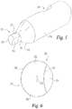
FIG. 5 is a perspective illustration of a distal end portion or foot of a shackle according to another embodiment. -
FIG. 6 is an end view of the distal tip of the foot illustrated inFIG. 5 . -
FIG. 7 is a perspective illustration of a distal end portion or foot of a shackle according to another embodiment. -
FIG. 8 is an end view of the distal tip of the foot illustrated inFIG. 7 . -
FIG. 9 is a perspective illustration of a distal end portion or foot of a shackle according to another embodiment. -
FIG. 10 is an end view of the distal tip of the foot illustrated inFIG. 9 . -
FIG. 11 is a perspective illustration of a distal end portion or foot of a shackle according to another embodiment. -
FIG. 12 is an end view of the distal tip of the foot illustrated inFIG. 11 . -
FIGS. 13a and 13b respectively illustrate an end view and a side view of a distal tip of the foot of a shackle according to another embodiment. -
FIGS. 14a and 14b respectively illustrate an end view and a side view of a distal tip of the foot of a shackle according to another embodiment. -
FIGS. 15a and 15b respectively illustrate an end view and a side view of a distal tip of the foot of a shackle according to another embodiment. -
FIGS. 16a and 16b respectively illustrate an end view and a side view of a distal tip of the foot of a shackle according to another embodiment. - For the purposes of promoting an understanding of the principles of the invention, reference will now be made to the embodiments illustrated in the drawings and specific language will be used to describe the same. It will nevertheless be understood that no limitation on the scope of the invention is hereby intended. Any alterations and further modifications in the described embodiments, and any further applications of the principles of the invention as described herein are contemplated as would normally occur to one skilled in the art to which the invention relates.
- With reference to
FIGS. 1 and2 , ahoop lock 100 according to one embodiment generally comprises ashackle 110 and acrossbar 120, which includes ahousing 130 and alocking mechanism 140. As described in further detail below, theshackle 110 andcrossbar 120 are separable, and thelocking mechanism 140 is configured to selectively secure thecrossbar 120 to theshackle 110. Thelock 100 may be used to secure afirst object 102 to asecond object 104 such as, for example, to prevent unauthorized separation or theft of theobjects - The
illustrative shackle 110 includes a pair oflegs 112 extending from opposite ends of acentral body 114. In the illustrated form, thelegs 112 are arranged substantially parallel to one another, and thecentral body 114 is curved or arcuate-shaped such that theshackle 110 is substantially U-shaped. However, it is also contemplated that theshackle 110 may take on another shape or configuration. For example, thecentral body 114 may be substantially rectilinear, or portions of thelegs 112 may be obliquely offset from one another. - Each of the
legs 112 comprises afoot 116, and thefeet 116 are arranged substantially parallel to one another. Eachfoot 116 includescylindrical portion 117, agroove 118 formed in thecylindrical portion 117, and atip 150. One or both of thelegs 112 may include a frustoconicaltapered portion 119 connecting thecylindrical portion 117 to thecorresponding tip 150. When theshackle 110 is coupled to thecrossbar 120, eachfoot 116 is positioned in thehousing 130. While other geometries are contemplated, the illustratedlegs 112,feet 116, andtapered portions 119 each have a substantially circular cross-section. Each of thetips 150, however, has a non-circular cross-section, as will be illustrated and described in further detail below. - The
exemplary housing 130 is configured as a tube defining aninternal cavity 132 in which thelocking mechanism 140 is positioned and seated. Thehousing 130 includes a pair of foot-receivingopenings 134 and a pair of tip-receivingopenings 136 aligned with the foot-receivingopenings 136. The foot-receivingopenings 134 are sized and configured to receive thefeet 116, and the tip-receivingopenings 136 are sized and configured to receive thetips 150. As illustrated inFIG. 2 , when theshackle 110 is coupled to thecrossbar 120, thetips 150 are positioned or seated in the tip-receivingopenings 136. - The
locking mechanism 140 is configured to secure theshackle 110 to thecrossbar 120 in a locked state, and to permit separation of theshackle 110 and thecrossbar 120 in an unlocked state. Theillustrative locking mechanism 140 generally includes alock cylinder 142, acam 144 connected to thelock cylinder 142, and a pair ofdeadbolts 146 engaged with thecam 144. Thelock cylinder 142 includes ashell 147 coupled to thehousing 130, and aspindle 148 which is rotatable with respect to theshell 147 upon insertion of a proper key 149 (FIG. 2 ). Thecam 144 is rotationally coupled with thespindle 148, and is configured to extend and retract thedeadbolts 146 in response to rotation of thespindle 148. While the illustratedlock mechanism 140 includes a key-operable lock cylinder 142, it is also contemplated that other forms of lock mechanism may be utilized. For example, in certain embodiments, thelock mechanism 140 may include a combination lock mechanism in addition to or in lieu of thelock cylinder 142. - In
FIG. 1 , thedeadbolts 146 are positioned in an extended position and are engaged with thefeet 116. More specifically, the end of eachdeadbolt 146 is received in thegroove 118 of one of thefeet 116. With thedeadbolts 146 engaged with thefeet 116, theshackle 110 cannot be removed from thecrossbar 120, thereby defining the locked state. When the key 149 is inserted and thespindle 148 is rotated, thecam 144 retracts thedeadbolts 146 to a retracted position. In the retracted position, thedeadbolts 146 do not engage thefeet 116, and theshackle 110 can be separated from thecrossbar 120, thereby defining the unlocked state. - With additional reference to
FIGS. 3 and 4 , eachtip 150 extends from a base 151 to anend surface 152. Thebase 151 is defined by the terminus of the taperedportion 119, and is substantially circular about acenter point 153. As illustrated inFIG. 4 , eachtip 150 has a non-circular cross-sectional geometry, and each tip-receivingopening 136 has a geometry corresponding to that of thetip 150. In the illustrated form, thetip 150 includes aflat engagement surface 154 and a curved orarcuate side surface 156 which defines a segment of a circle formed about thecenter point 153. Theengagement surface 154 may, for example, define a 45° angle with respect to two perpendicular radii of thearcuate surface 156. While the illustratedengagement surface 154 is obliquely offset with respect to a depth dimension of thegroove 118, it is also contemplated that theengagement surface 154 may be arranged parallel or perpendicular to the depth dimension of thegroove 118. - During manufacture, the
tip 150 may initially be configured as a substantially cylindrical tip extending from thecircular base 151. Theengagement surface 154 may be formed by milling or machining away a portion of the cylindrical tip. For example, a milling bit may be passed along a straight line offset from and arranged parallel to a diameter of thebase 151. - With specific reference to
FIGS. 2 and4 , when theshackle 110 is coupled to thecrossbar 120, thenon-circular tips 150 are received in the tip-receivingopenings 136. The tip-receivingopenings 136 are configured to receive and matingly engage thetips 150 such that thetips 150 are rotationally coupled to thehousing 130. Each of the tip-receivingopenings 136 may have a geometry corresponding to the non-circular cross-section of thetip 150. As illustrated inFIG. 4 , each tip-receivingopening 136 includes aflat engagement edge 137 corresponding to theflat engagement surface 154, and a curved orarcuate edge 138 corresponding to the curved orarcuate side surface 156. The tip-receivingopenings 136 and thetips 150 may be configured such that each tip-receivingopening 136 is capable of receiving each of thetips 150, thereby enabling theshackle 110 to be coupled to thecrossbar 120 in either of two orientations. For example, the tip-receivingopenings 136 may be mirror images of one another, and thetips 150 may likewise be mirror images of one another. - A common form of attempting to defeat a hoop lock (such as the lock 100) is to cut through one of the
legs 112, as depicted by thecut 106 illustrated inFIG. 1 . Once theleg 112 is cut, the attacker manually rotates theuncut leg 112, using thecentral body 114 as a lever arm. If thecentral body 114 is sufficiently rotated, a gap forms at thecut 106, thereby allowing one or both of theobjects shackle 110 through the gap. While the deadbolts of conventional hoop locks resist rotation of the legs, it has been found that certain conventional systems remain susceptible to the above-described type of cut attack. - With the
shackle 110 coupled to thecrossbar 120 as described above, engagement between the tip-receivingopenings 136 and thetips 150 rotationally couples thefeet 116 to thehousing 130. As a result, thecrossbar 120 substantially prevents rotation of thelegs 112, thereby preventing formation of the above-described gap. The term "substantially" as used herein may be applied to modify a quantitative representation which could permissibly vary without resulting in a change in the basic function to which it relates. For example, with thetip 150 engaged with the tip-receivingopening 136, theleg 116 may permissibly be capable of slight rotation if the above-described gap formation is prevented. With thelegs 112 unable to rotate, the attacker must make asecond cut 108 in theshackle 110 such that a portion of theshackle 110 can be removed to form a gap through which theobjects -
FIGS. 5-10 depict tip-receiving openings and feet including tips according to other embodiments. The tip-receiving openings, feet, and tips are shaped and configured substantially similar to the tip-receivingopenings 136,feet 116 andtips 150. Unless indicated otherwise, similar reference characters are used to indicate similar elements and features. In the interest of conciseness, the following descriptions focus primarily on features that are different than those described above with regard to the tip-receivingopenings 136,feet 116 andtips 150. - With reference to
FIGS. 5 and 6 , atip 250 according to one embodiment includes a curved orarcuate side surface 256 and a concavearcuate engagement surface 254. The tip-receivingopening 236 has a geometry corresponding to that of thetip 250, and includes aconvex engagement edge 237 corresponding to theconcave engagement surface 254. In the illustrated form, thearcuate engagement surface 254 has an arc radius greater than that of thearcuate side surface 256. In other embodiments, the arc radius of theconcave engagement surface 254 may be equal to or less than that of thearcuate side surface 256. Additionally, while theexemplary engagement surface 254 is formed on the opposite side of thecenter point 253 as thegroove 218, it is also contemplated that the engagement surface may be oriented and arranged in another manner. - During manufacture, the
tip 250 may begin as a substantially cylindrical tip having a circular cross-section corresponding to that of thebase 251, and theengagement surface 254 may be formed by milling or machining away a portion of the cylindrical tip. For example, a milling bit may be passed along a straight line toward thecenter point 253 such that theengagement surface 254 has a radius of curvature corresponding to the radius of the milling bit. - With reference to
FIGS. 7 and 8 , atip 350 according to another embodiment includes aconvex engagement surface 354 which has an arc radius greater than that of thearcuate side surface 356. The tip-receivingopening 336 is defined, in part, by aconcave engagement edge 337 corresponding to theconvex engagement surface 354. - With reference to
FIGS. 9 and 10 , atip 450 according to another embodiment includes a pair of flat engagement surfaces 454 that join or intersect one another at avertex 455. The tip-receivingopening 436 likewise includes a pair ofengagement edges 437 joining one another at a vertex. While the illustrated engagement surfaces 454 are arranged substantially perpendicular to one another, it is also contemplated that the engagement surfaces 454 may be offset from one another at an oblique angle. In such forms, the engagement edges 437 may be offset from one another at a substantially equivalent oblique angle. - With reference to
FIGS. 11 and 12 , atip 550 according to another embodiment includes a pair ofengagement surfaces 554 and a pair of curved or arcuate side surfaces 556 connecting the engagement surfaces 554. The tip-receivingopening 536 likewise includes a pair of flat engagement edges 537 and a pair ofarcuate edges 538 connecting the engagement edges 537. In the illustrated form, the engagement surfaces 554 are obliquely offset from one another. In other embodiments, two or more flat engagement surfaces may be arranged parallel with or perpendicular to one another, and at least some of the flat engagement surfaces may be formed adjacent the curved or arcuate side surfaces. -
FIGS. 13-16 depict feet including tips according to further embodiments. Each of the feet is configured substantially similar to thefeet 116, and each of the tips is configured substantially similar to thetips 150. Unless indicated otherwise, similar reference characters are used to indicate similar elements and features. In the interest of conciseness, the following descriptions focus primarily on features that are different than those described above with regard to thefeet 116 andtips 150. While not specifically illustrated, it should be understood that a tip-receiving opening in each of the embodiments described hereinafter may have a shape corresponding to that of the tip. - With reference to
FIGS. 13a and 13b , atip 650 according to another embodiment includes four flat engagement surfaces 654. Each of the engagement surfaces 654 is arranged either parallel or perpendicular to a depth dimension of thegroove 618 such that theface 652 is substantially square-shaped. Additionally, thetip 650 is positioned and arranged generally concentric with thefoot 616, and the greatest dimension of theface 652 is less than the diameter of thefoot 616. - With reference to
FIGS. 14a and 14b , atip 750 according to another embodiment includes four flat engagement surfaces 754. Each of the engagement surfaces 754 is angularly offset, for example, by about 45° with respect to a depth dimension of thegroove 718, thereby resulting in aface 752 that is diamond-shaped. Additionally, the greatest dimension of theface 752 is substantially equal to the diameter of thefoot 716 such that the diamond-shapedface 752 is circumscribed by the circular cross-section of thefoot 716. - With reference to
FIGS. 15a and 15b , atip 850 according to another embodiment includes four flat engagement surfaces 854. Each of the engagement surfaces 854 is arranged either parallel or perpendicular to a depth dimension of thegroove 818 such that theface 852 is substantially square-shaped. Additionally, the greatest dimension of theface 852 is substantially equal to the diameter of thefoot 816 such that the square-shapedface 852 is circumscribed by the circular cross-section of thefoot 816. - With reference to
FIGS. 16a and 16b , atip 950 according to another embodiment includes a pair of parallel engagement surfaces 954 connected by a pair of curved orarcuate surfaces 956. In the illustrated form, the engagement surfaces 954 are arranged substantially parallel to the depth dimension of thegroove 918. In other embodiments, the engagement surfaces 954 may be arranged substantially perpendicular to or obliquely offset with respect to the depth dimension of thegroove 918. - While the invention has been illustrated and described in detail in the drawings and foregoing description, the same is to be considered as illustrative and not restrictive in character, it being understood that only the preferred embodiments have been shown and described and that all changes and modifications that come within the spirit of the inventions are desired to be protected.
- It should be understood that while the use of words such as preferable, preferably, preferred or more preferred utilized in the description above indicate that the feature so described may be more desirable, it nonetheless may not be necessary and embodiments lacking the same may be contemplated as within the scope of the invention, the scope being defined by the claims that follow. In reading the claims, it is intended that when words such as "a," "an," "at least one," or "at least one portion" are used there is no intention to limit the claim to only one item unless specifically stated to the contrary in the claim. When the language "at least a portion" and/or "a portion" is used the item can include a portion and/or the entire item unless specifically stated to the contrary.
Claims (15)
- An apparatus (100), comprising:a shackle (110) comprising:a body portion (114);a first leg (112) extending from the body portion (114) and including a first foot (116; 216; 316; 416; 516; 616; 716; 816; 916); anda second leg (112) extending from the body portion (114) and including a second foot (116; 216; 316; 416; 516; 616; 716; 816; 916);wherein each foot (116; 216; 316; 416; 516; 616; 716; 816; 916) comprises:a tip portion (150; 250; 350; 450; 550; 650; 750; 850; 950) having a non-circular outer cross-section; anda groove (118; 218; 318; 418; 518; 618; 718; 818; 918); anda tubular housing (130) extending in a longitudinal direction and including:an internal cavity (132);a pair of first openings (134) offset from one another in the longitudinal direction and sized and configured to receive the first and second feet (116; 216; 316; 416; 516; 616; 716; 816; 916); anda pair of second openings (136) offset from one another in the longitudinal direction and sized and configured to receive the tip portions (150; 250; 350; 450; 550; 650; 750; 850; 950) of the first and second feet (116; 216; 316; 416; 516; 616; 716; 816; 916), each of the second openings (136) having a non-circular inner cross section corresponding to the non-circular outer cross section of the tip portions (150; 250; 350; 450; 550; 650; 750; 850; 950);wherein the first and second feet (116; 216; 316; 416; 516; 616; 716; 816; 916) extend through the pair of first openings (134) such that the tip portions (150; 250; 350; 450; 550; 650; 750; 850; 950) are received in the second openings (136); anda lock mechanism (140) including a pair of deadbolts (146) positioned in the housing (130), the lock mechanism (140) having a locked state in which each deadbolt (146) is engaged with the groove (118; 218; 318; 418; 518; 618; 718; 818; 918) of a corresponding one of the feet (116; 216; 316; 416; 516; 616; 716; 816; 916) and retains the corresponding foot (116; 216; 316; 416; 516; 616; 716; 816; 916) within the housing (130), and an unlocked state in which the deadbolts (146) do not prevent removal of the feet (116; 216; 316; 416; 516; 616; 716; 816; 916) from the housing (130).
- The apparatus (100) of claim 1, wherein the non-circular outer cross-section of each tip portion (150; 250; 350; 450; 550; 950) comprises an arcuate segment (156; 256; 356; 456; 556; 856; 956) and at least one additional segment (154; 254; 354; 454; 554; 954).
- The apparatus (100) of claim 2, wherein the at least one additional segment comprises at least one straight segment (154; 454; 554; 954).
- The apparatus (100) of claim 3, wherein the at least one straight segment comprises a first straight segment (454; 554; 954) and a second straight segment (454; 554; 954).
- The apparatus (100) of claim 4, wherein the non-circular outer cross-section of each tip portion (550; 950) further comprises a second arcuate segment (556; 956), wherein the first straight segment (554; 954) and the second straight segment (554; 954) connect the arcuate segment (556; 956) and the second arcuate segment (556; 956).
- The apparatus (100) of claim 4, wherein the first straight segment (454; 554) and the second straight segment (454; 554) are angled relative to one another.
- The apparatus (100) of claim 6, wherein the first straight segment (454) and the second straight segment (454) meet at a vertex (455).
- The apparatus (100) of claim 2, wherein the at least one additional segment is at least one curved segment (254; 354).
- The apparatus (100) of claim 1, wherein the outer cross-section of each tip portion (250; 350) is crescent-shaped.
- The apparatus (100) of claim 1, wherein the outer cross-section of each tip portion (150) is D-shaped.
- The apparatus (100) of claim 1, wherein each foot (116; 216; 316; 416; 516; 616; 716; 816; 916) further comprises a cylindrical portion (117) having a circular outer cross-section; and
wherein the cylindrical portions (117) of the feet (116; 216; 316; 416; 516; 616; 716; 816; 916) are received in the pair of first openings (134). - An apparatus (100), comprising:a shackle (110) comprising a pair of legs (112), each leg including a foot portion (116; 216; 316; 416; 516; 616; 716; 816; 916) defining a groove (118; 218; 318; 418; 518; 618; 718; 818; 918) and a tip (150; 250; 350; 450; 550; 650; 750; 850; 950) having an outer cross-section;a tubular cross-bar (120) extending in a longitudinal direction, the cross-bar including a pair of first openings (134) and a pair of second openings (136), the cross-bar (120) including an internal cavity (132) in communication with the openings (134, 136), wherein the first openings (134) are offset from one another in the longitudinal direction and the legs (112) extend through the first openings (134), wherein the second openings (136) are offset from one another in the longitudinal direction and the tip (150; 250; 350; 450; 550; 650; 750; 850; 950) of each foot portion (116; 216; 316; 416; 516; 616; 716; 816; 916) is received in a corresponding and respective one of the second openings (136), and wherein each of the second openings (136) has an inner cross-section corresponding to the outer cross-section of the tip (150; 250; 350; 450; 550; 650; 750; 850; 950) of the corresponding leg (112); anda lock mechanism (140) positioned in the internal cavity (132) of the cross-bar (120) and including a pair of deadbolts (146), the lock mechanism (140) having a locked state in which each deadbolt (146) is engaged with the groove (118; 218; 318; 418; 518; 618; 718; 818; 918) of a corresponding one of the foot portions (116; 216; 316; 416; 516; 616; 716; 816; 916) and retains the corresponding foot portion (116; 216; 316; 416; 516; 616; 716; 816; 916) in engagement with the cross-bar (120), the lock mechanism (140) having an unlocked state in which the deadbolts (146) do not prevent removal of the foot portion (116; 216; 316; 416; 516; 616; 716; 816; 916) from the cross-bar (120); andwherein the outer cross-section of each tip (150; 250; 350; 450; 550; 650; 750; 850; 950) and the inner cross-section of each second opening (136) in the cross-bar (120) has a non-circular shape.
- The apparatus (100) of claim 12, wherein each of the second openings (136) in the cross-bar (120) has a size and shape corresponding to the outer cross-section of the corresponding tip (150; 250; 350; 450; 550; 650; 750; 850; 950).
- The apparatus (100) of claim 13, wherein the outer cross-section of each tip portion (150; 250; 350) is either crescent-shaped or D-shaped.
- An apparatus (100), comprising:a shackle (110) comprising a pair of feet (116; 216; 316), each foot (116; 216; 316) including a tip portion (150; 250; 350) having a non-circular outer cross-section;a cross-bar (120) extending along a longitudinal axis, the cross-bar (120) comprising:an internal cavity (132) extending along the longitudinal axis;a pair of first openings (134), wherein the pair of first openings (134) are longitudinally offset from one another; anda pair of second openings (136), wherein the pair of second openings (136) are longitudinally offset from one another and are positioned diametrically opposite the pair of first openings (134), wherein each of the second openings (136) has a non-circular inner cross-section corresponding to the non-circular outer cross-section of the tip portion (150; 250; 350) such that the second openings (136) are sized and shaped to matingly receive the tip portions (150; 250; 350) of the feet (116; 216; 316); anda lock mechanism (140) positioned in the internal cavity (132) and comprising a pair of deadbolts (146), the lock mechanism (140) having a locking state in which the deadbolts (146) prevent removal of the feet (116; 216; 316) from the cross-bar (120), the locking mechanism (140) having an unlocked state in which the deadbolts (146) do not prevent removal of the feet (116; 216; 316) from the cross-bar (120);wherein the non-circular outer cross-section of each tip portion (150; 250; 350) is either crescent-shaped or D-shaped; andwherein the pair of feet (116; 216; 316) are operable to extend through the pair of first openings (134) such that the tip portions (150; 250; 350) are received in the second openings (136).
Applications Claiming Priority (3)
| Application Number | Priority Date | Filing Date | Title |
|---|---|---|---|
| US201462040929P | 2014-08-22 | 2014-08-22 | |
| PCT/US2015/046572 WO2016029212A1 (en) | 2014-08-22 | 2015-08-24 | Hoop lock with anti-rotation features |
| EP15833601.6A EP3183405B1 (en) | 2014-08-22 | 2015-08-24 | Hoop lock with anti-rotation features |
Related Parent Applications (1)
| Application Number | Title | Priority Date | Filing Date |
|---|---|---|---|
| EP15833601.6A Division EP3183405B1 (en) | 2014-08-22 | 2015-08-24 | Hoop lock with anti-rotation features |
Publications (3)
| Publication Number | Publication Date |
|---|---|
| EP3584394A1 true EP3584394A1 (en) | 2019-12-25 |
| EP3584394B1 EP3584394B1 (en) | 2022-01-26 |
| EP3584394B2 EP3584394B2 (en) | 2026-01-07 |
Family
ID=55347842
Family Applications (2)
| Application Number | Title | Priority Date | Filing Date |
|---|---|---|---|
| EP15833601.6A Active EP3183405B1 (en) | 2014-08-22 | 2015-08-24 | Hoop lock with anti-rotation features |
| EP19190222.0A Active EP3584394B2 (en) | 2014-08-22 | 2015-08-24 | Hoop lock with anti-rotation features |
Family Applications Before (1)
| Application Number | Title | Priority Date | Filing Date |
|---|---|---|---|
| EP15833601.6A Active EP3183405B1 (en) | 2014-08-22 | 2015-08-24 | Hoop lock with anti-rotation features |
Country Status (7)
| Country | Link |
|---|---|
| US (4) | US9670698B2 (en) |
| EP (2) | EP3183405B1 (en) |
| CN (1) | CN107075879B (en) |
| CA (1) | CA2961339C (en) |
| DK (2) | DK3584394T4 (en) |
| FI (1) | FI3584394T4 (en) |
| WO (1) | WO2016029212A1 (en) |
Cited By (4)
| Publication number | Priority date | Publication date | Assignee | Title |
|---|---|---|---|---|
| WO2023052778A1 (en) | 2021-09-29 | 2023-04-06 | Zeal Innovation Ltd | Security devices |
| WO2023187416A1 (en) | 2022-04-01 | 2023-10-05 | Zeal Innovation Ltd | Locking mechanism with anti-rotation |
| DE202024105302U1 (en) | 2024-09-13 | 2024-10-08 | Zeal Innovation Ltd | safety device |
| EP4717380A1 (en) | 2024-09-13 | 2026-04-01 | Zeal Innovation Ltd | Security device |
Families Citing this family (4)
| Publication number | Priority date | Publication date | Assignee | Title |
|---|---|---|---|---|
| CN107075879B (en) | 2014-08-22 | 2019-12-13 | 施拉奇锁有限责任公司 | Hoop lock with anti-rotation feature |
| JP1616132S (en) * | 2017-07-28 | 2018-10-22 | ||
| US10577833B1 (en) * | 2018-08-10 | 2020-03-03 | Schlage Lock Company Llc | Compact bike lock |
| US11377876B2 (en) * | 2019-01-28 | 2022-07-05 | Ino Vision Ltd. | Magnetic keeper for bicycle lock element |
Citations (4)
| Publication number | Priority date | Publication date | Assignee | Title |
|---|---|---|---|---|
| US5372019A (en) * | 1993-09-24 | 1994-12-13 | Hsiao; Yung-Chi | Automobile steering lock |
| US5398529A (en) * | 1991-03-07 | 1995-03-21 | Goldman; David S. | Tamper-resistant lock |
| US7389659B1 (en) * | 2005-12-22 | 2008-06-24 | Carroll Diaz | Shackle apparatus |
| DE202013103393U1 (en) * | 2013-07-26 | 2013-08-19 | Sheng Yung Lock Industrial Co., Ltd. | Castle construction |
Family Cites Families (34)
| Publication number | Priority date | Publication date | Assignee | Title |
|---|---|---|---|---|
| US116977A (en) * | 1871-07-11 | Improvement in padlocks | ||
| US526740A (en) * | 1894-10-02 | rapaport | ||
| US1490988A (en) * | 1923-02-17 | 1924-04-22 | Harry E Soref | Combined padlock and doorbolt |
| US2824439A (en) * | 1956-07-13 | 1958-02-25 | Master Lock Co | Tamper-proof padlock |
| US3908415A (en) * | 1974-05-28 | 1975-09-30 | Master Lock Co | Padlock with deflectable shackle section |
| DE2706302C3 (en) † | 1977-02-15 | 1981-10-08 | Aug. Bremicker Söhne KG, 5802 Wetter | Insert bracket with associated insertion channel training in a lock housing of a padlock |
| DE3228613A1 (en) * | 1982-07-30 | 1984-02-02 | Fa. Aug. Winkhaus, 4404 Telgte | Long-shackle lock, especially for two-wheeled vehicles |
| US4674306A (en) * | 1985-09-16 | 1987-06-23 | Offer Halpern | Vehicle and assembly locking and wrenching apparatus |
| DE3815584C1 (en) * | 1988-05-06 | 1989-08-10 | Aug. Winkhaus Gmbh & Co Kg, 4404 Telgte, De | |
| US4918951A (en) | 1989-06-29 | 1990-04-24 | Abraham Kavizky | Locking device particularly useful for locking motorcycles, bicycles and the like |
| US5101646A (en) † | 1991-03-07 | 1992-04-07 | Goldman David S | Tamper-resistant lock |
| DE9212843U1 (en) * | 1992-09-24 | 1992-11-26 | ABUS August Bremicker Söhne KG, 5802 Wetter | Holder for attaching a U-lock to a bicycle |
| US5490402A (en) * | 1993-10-22 | 1996-02-13 | Shieh; Jin-Ren | Padlock |
| US5406812A (en) * | 1994-05-16 | 1995-04-18 | Jaw; Chin-Woei | Structure of bicycle lock |
| US5417092A (en) * | 1994-06-02 | 1995-05-23 | Iu; Chien-Chzh | Padlock |
| US5561996A (en) * | 1994-08-30 | 1996-10-08 | Chang; Chao S. | Gearshift lock |
| US5921116A (en) * | 1997-02-26 | 1999-07-13 | Bruce L. Adams | Vehicle pedal lock |
| US6341509B1 (en) | 1999-09-03 | 2002-01-29 | Kryptonite Corporation | Tie lock assemblage with replaceable lock mechanism |
| DE10026701A1 (en) * | 2000-05-30 | 2001-12-06 | Bremicker Soehne Kg A | U-lock |
| US6694781B1 (en) * | 2003-05-21 | 2004-02-24 | Vulcan Sports Co., Ltd. | Tow-deterrent lock for camping trailers |
| CN2679313Y (en) * | 2004-03-16 | 2005-02-16 | 徐钜祥 | Lock of U-shape tapered end |
| EP1637679A1 (en) * | 2004-09-21 | 2006-03-22 | Magnum Industries Limited | Padlock, in particular for bicycles |
| US8061169B2 (en) * | 2005-09-15 | 2011-11-22 | Pinhead Components, Inc. | Locking system with hidden keyed access |
| CN2921214Y (en) † | 2006-07-14 | 2007-07-11 | 唐洪勇 | Antitheft lock |
| DE102007035122A1 (en) * | 2007-07-27 | 2009-01-29 | ABUS August Bremicker Söhne KG | lock |
| US7694541B2 (en) * | 2008-05-06 | 2010-04-13 | Abus August Bremicker Soehne Kg | Padlock having a preloaded locking member |
| WO2009158326A2 (en) * | 2008-06-25 | 2009-12-30 | Ingersoll-Rand Company | Portable lock with modular cable |
| DE102009030034A1 (en) * | 2009-06-23 | 2010-12-30 | ABUS August Bremicker Söhne KG | U-lock |
| CN101877643B (en) * | 2010-06-29 | 2014-12-10 | 中兴通讯股份有限公司 | Multipoint sound-mixing distant view presenting method, device and system |
| US8640507B1 (en) * | 2011-09-09 | 2014-02-04 | Jay S. Derman | Horizontal shackle for lock system and method |
| US20140076010A1 (en) * | 2012-09-14 | 2014-03-20 | Scott Gold | Multi-access lock |
| US20160201357A1 (en) * | 2013-08-26 | 2016-07-14 | David L. George | Tamper resistant bicycle lock |
| CN107075879B (en) * | 2014-08-22 | 2019-12-13 | 施拉奇锁有限责任公司 | Hoop lock with anti-rotation feature |
| US10557288B2 (en) * | 2015-04-17 | 2020-02-11 | Schlage Lock Company Llc | Hoop lock with bent foot engagement |
-
2015
- 2015-08-24 CN CN201580057577.9A patent/CN107075879B/en active Active
- 2015-08-24 DK DK19190222.0T patent/DK3584394T4/en active
- 2015-08-24 EP EP15833601.6A patent/EP3183405B1/en active Active
- 2015-08-24 FI FIEP19190222.0T patent/FI3584394T4/en active
- 2015-08-24 CA CA2961339A patent/CA2961339C/en active Active
- 2015-08-24 WO PCT/US2015/046572 patent/WO2016029212A1/en not_active Ceased
- 2015-08-24 DK DK15833601T patent/DK3183405T3/en active
- 2015-08-24 EP EP19190222.0A patent/EP3584394B2/en active Active
- 2015-08-24 US US14/834,105 patent/US9670698B2/en active Active
-
2017
- 2017-06-06 US US15/615,036 patent/US10240367B2/en active Active
-
2019
- 2019-03-21 US US16/360,671 patent/US10808428B2/en active Active
-
2020
- 2020-10-20 US US17/075,286 patent/US11828090B2/en active Active
Patent Citations (4)
| Publication number | Priority date | Publication date | Assignee | Title |
|---|---|---|---|---|
| US5398529A (en) * | 1991-03-07 | 1995-03-21 | Goldman; David S. | Tamper-resistant lock |
| US5372019A (en) * | 1993-09-24 | 1994-12-13 | Hsiao; Yung-Chi | Automobile steering lock |
| US7389659B1 (en) * | 2005-12-22 | 2008-06-24 | Carroll Diaz | Shackle apparatus |
| DE202013103393U1 (en) * | 2013-07-26 | 2013-08-19 | Sheng Yung Lock Industrial Co., Ltd. | Castle construction |
Cited By (6)
| Publication number | Priority date | Publication date | Assignee | Title |
|---|---|---|---|---|
| WO2023052778A1 (en) | 2021-09-29 | 2023-04-06 | Zeal Innovation Ltd | Security devices |
| DE202022002833U1 (en) | 2021-09-29 | 2023-10-26 | Zeal Innovation Ltd | Safety devices |
| EP4624710A2 (en) | 2021-09-29 | 2025-10-01 | Zeal Innovation Ltd | Security devices |
| WO2023187416A1 (en) | 2022-04-01 | 2023-10-05 | Zeal Innovation Ltd | Locking mechanism with anti-rotation |
| DE202024105302U1 (en) | 2024-09-13 | 2024-10-08 | Zeal Innovation Ltd | safety device |
| EP4717380A1 (en) | 2024-09-13 | 2026-04-01 | Zeal Innovation Ltd | Security device |
Also Published As
| Publication number | Publication date |
|---|---|
| US9670698B2 (en) | 2017-06-06 |
| CA2961339A1 (en) | 2016-02-25 |
| US11828090B2 (en) | 2023-11-28 |
| FI3584394T4 (en) | 2026-03-03 |
| US10240367B2 (en) | 2019-03-26 |
| EP3183405A4 (en) | 2018-03-14 |
| US20160053515A1 (en) | 2016-02-25 |
| US20170306655A1 (en) | 2017-10-26 |
| EP3584394B1 (en) | 2022-01-26 |
| WO2016029212A1 (en) | 2016-02-25 |
| CN107075879A (en) | 2017-08-18 |
| EP3584394B2 (en) | 2026-01-07 |
| EP3183405A1 (en) | 2017-06-28 |
| CN107075879B (en) | 2019-12-13 |
| US20210277688A1 (en) | 2021-09-09 |
| DK3183405T3 (en) | 2019-11-11 |
| EP3183405B1 (en) | 2019-08-07 |
| US20190218827A1 (en) | 2019-07-18 |
| US10808428B2 (en) | 2020-10-20 |
| CA2961339C (en) | 2019-08-27 |
| DK3584394T4 (en) | 2026-02-23 |
| DK3584394T3 (en) | 2022-03-21 |
Similar Documents
| Publication | Publication Date | Title |
|---|---|---|
| US10808428B2 (en) | Hoop lock with anti-rotation features | |
| US11746567B2 (en) | Hoop lock with dual locking | |
| US10557288B2 (en) | Hoop lock with bent foot engagement | |
| US10240364B2 (en) | Key or key blank for a disk cylinder and associated disk cylinder | |
| US9297185B2 (en) | Padlock | |
| US6925844B2 (en) | Lock having a helical keyway and accompanying key and methods therefor | |
| CA2828067A1 (en) | Radially reciprocating lock | |
| US20070186601A1 (en) | Resettable tumbler lock | |
| AU2009201742B2 (en) | Padlock having a preloaded locking member | |
| US20030041637A1 (en) | Cylinder lock with tumbler plates | |
| JP2016138423A (en) | Cylinder lock key | |
| US3384386A (en) | Surgical knife with removable blade | |
| CN105415254A (en) | Mounting wrench for a tool head | |
| EP1536091A1 (en) | Motorcycle lock with multi-stage locking and unlocking | |
| WO2015174828A1 (en) | Device for connecting a door lock with two door handles | |
| WO2014167187A1 (en) | Handle-equipped lock | |
| TWM309593U (en) | Improved structure of key | |
| TW202210702A (en) | Lock and related key | |
| WO2017037513A1 (en) | Cam advantageously for inserting into lock body | |
| HK1194118B (en) | Lock assembly with movable element |
Legal Events
| Date | Code | Title | Description |
|---|---|---|---|
| PUAI | Public reference made under article 153(3) epc to a published international application that has entered the european phase |
Free format text: ORIGINAL CODE: 0009012 |
|
| STAA | Information on the status of an ep patent application or granted ep patent |
Free format text: STATUS: THE APPLICATION HAS BEEN PUBLISHED |
|
| AC | Divisional application: reference to earlier application |
Ref document number: 3183405 Country of ref document: EP Kind code of ref document: P |
|
| AK | Designated contracting states |
Kind code of ref document: A1 Designated state(s): AL AT BE BG CH CY CZ DE DK EE ES FI FR GB GR HR HU IE IS IT LI LT LU LV MC MK MT NL NO PL PT RO RS SE SI SK SM TR |
|
| STAA | Information on the status of an ep patent application or granted ep patent |
Free format text: STATUS: REQUEST FOR EXAMINATION WAS MADE |
|
| 17P | Request for examination filed |
Effective date: 20200625 |
|
| RBV | Designated contracting states (corrected) |
Designated state(s): AL AT BE BG CH CY CZ DE DK EE ES FI FR GB GR HR HU IE IS IT LI LT LU LV MC MK MT NL NO PL PT RO RS SE SI SK SM TR |
|
| GRAP | Despatch of communication of intention to grant a patent |
Free format text: ORIGINAL CODE: EPIDOSNIGR1 |
|
| STAA | Information on the status of an ep patent application or granted ep patent |
Free format text: STATUS: GRANT OF PATENT IS INTENDED |
|
| INTG | Intention to grant announced |
Effective date: 20210223 |
|
| GRAJ | Information related to disapproval of communication of intention to grant by the applicant or resumption of examination proceedings by the epo deleted |
Free format text: ORIGINAL CODE: EPIDOSDIGR1 |
|
| STAA | Information on the status of an ep patent application or granted ep patent |
Free format text: STATUS: REQUEST FOR EXAMINATION WAS MADE |
|
| INTC | Intention to grant announced (deleted) | ||
| GRAP | Despatch of communication of intention to grant a patent |
Free format text: ORIGINAL CODE: EPIDOSNIGR1 |
|
| STAA | Information on the status of an ep patent application or granted ep patent |
Free format text: STATUS: GRANT OF PATENT IS INTENDED |
|
| INTG | Intention to grant announced |
Effective date: 20210730 |
|
| RIN1 | Information on inventor provided before grant (corrected) |
Inventor name: KINDSTRAND, DANIEL HUGH Inventor name: KUMAR, HASSAN CHARAN Inventor name: RAMAKRISHNA, MANJUNATHA Inventor name: MILLER, DAVID BRUCE |
|
| GRAS | Grant fee paid |
Free format text: ORIGINAL CODE: EPIDOSNIGR3 |
|
| GRAA | (expected) grant |
Free format text: ORIGINAL CODE: 0009210 |
|
| STAA | Information on the status of an ep patent application or granted ep patent |
Free format text: STATUS: THE PATENT HAS BEEN GRANTED |
|
| AC | Divisional application: reference to earlier application |
Ref document number: 3183405 Country of ref document: EP Kind code of ref document: P |
|
| AK | Designated contracting states |
Kind code of ref document: B1 Designated state(s): AL AT BE BG CH CY CZ DE DK EE ES FI FR GB GR HR HU IE IS IT LI LT LU LV MC MK MT NL NO PL PT RO RS SE SI SK SM TR |
|
| REG | Reference to a national code |
Ref country code: GB Ref legal event code: FG4D |
|
| REG | Reference to a national code |
Ref country code: CH Ref legal event code: EP |
|
| REG | Reference to a national code |
Ref country code: AT Ref legal event code: REF Ref document number: 1465417 Country of ref document: AT Kind code of ref document: T Effective date: 20220215 |
|
| REG | Reference to a national code |
Ref country code: IE Ref legal event code: FG4D |
|
| REG | Reference to a national code |
Ref country code: DE Ref legal event code: R096 Ref document number: 602015076760 Country of ref document: DE |
|
| REG | Reference to a national code |
Ref country code: FI Ref legal event code: FGE |
|
| REG | Reference to a national code |
Ref country code: DK Ref legal event code: T3 Effective date: 20220318 |
|
| REG | Reference to a national code |
Ref country code: SE Ref legal event code: TRGR |
|
| REG | Reference to a national code |
Ref country code: NL Ref legal event code: FP |
|
| REG | Reference to a national code |
Ref country code: LT Ref legal event code: MG9D |
|
| REG | Reference to a national code |
Ref country code: NO Ref legal event code: T2 Effective date: 20220126 |
|
| REG | Reference to a national code |
Ref country code: AT Ref legal event code: MK05 Ref document number: 1465417 Country of ref document: AT Kind code of ref document: T Effective date: 20220126 |
|
| PG25 | Lapsed in a contracting state [announced via postgrant information from national office to epo] |
Ref country code: RS Free format text: LAPSE BECAUSE OF FAILURE TO SUBMIT A TRANSLATION OF THE DESCRIPTION OR TO PAY THE FEE WITHIN THE PRESCRIBED TIME-LIMIT Effective date: 20220126 Ref country code: PT Free format text: LAPSE BECAUSE OF FAILURE TO SUBMIT A TRANSLATION OF THE DESCRIPTION OR TO PAY THE FEE WITHIN THE PRESCRIBED TIME-LIMIT Effective date: 20220526 Ref country code: LT Free format text: LAPSE BECAUSE OF FAILURE TO SUBMIT A TRANSLATION OF THE DESCRIPTION OR TO PAY THE FEE WITHIN THE PRESCRIBED TIME-LIMIT Effective date: 20220126 Ref country code: HR Free format text: LAPSE BECAUSE OF FAILURE TO SUBMIT A TRANSLATION OF THE DESCRIPTION OR TO PAY THE FEE WITHIN THE PRESCRIBED TIME-LIMIT Effective date: 20220126 Ref country code: ES Free format text: LAPSE BECAUSE OF FAILURE TO SUBMIT A TRANSLATION OF THE DESCRIPTION OR TO PAY THE FEE WITHIN THE PRESCRIBED TIME-LIMIT Effective date: 20220126 Ref country code: BG Free format text: LAPSE BECAUSE OF FAILURE TO SUBMIT A TRANSLATION OF THE DESCRIPTION OR TO PAY THE FEE WITHIN THE PRESCRIBED TIME-LIMIT Effective date: 20220426 |
|
| PG25 | Lapsed in a contracting state [announced via postgrant information from national office to epo] |
Ref country code: PL Free format text: LAPSE BECAUSE OF FAILURE TO SUBMIT A TRANSLATION OF THE DESCRIPTION OR TO PAY THE FEE WITHIN THE PRESCRIBED TIME-LIMIT Effective date: 20220126 Ref country code: LV Free format text: LAPSE BECAUSE OF FAILURE TO SUBMIT A TRANSLATION OF THE DESCRIPTION OR TO PAY THE FEE WITHIN THE PRESCRIBED TIME-LIMIT Effective date: 20220126 Ref country code: GR Free format text: LAPSE BECAUSE OF FAILURE TO SUBMIT A TRANSLATION OF THE DESCRIPTION OR TO PAY THE FEE WITHIN THE PRESCRIBED TIME-LIMIT Effective date: 20220427 Ref country code: AT Free format text: LAPSE BECAUSE OF FAILURE TO SUBMIT A TRANSLATION OF THE DESCRIPTION OR TO PAY THE FEE WITHIN THE PRESCRIBED TIME-LIMIT Effective date: 20220126 |
|
| PG25 | Lapsed in a contracting state [announced via postgrant information from national office to epo] |
Ref country code: IS Free format text: LAPSE BECAUSE OF FAILURE TO SUBMIT A TRANSLATION OF THE DESCRIPTION OR TO PAY THE FEE WITHIN THE PRESCRIBED TIME-LIMIT Effective date: 20220526 |
|
| REG | Reference to a national code |
Ref country code: DE Ref legal event code: R055 Ref document number: 602015076760 Country of ref document: DE |
|
| PLCP | Request for limitation filed |
Free format text: ORIGINAL CODE: EPIDOSNLIM1 |
|
| REG | Reference to a national code |
Ref country code: DE Ref legal event code: R026 Ref document number: 602015076760 Country of ref document: DE |
|
| PG25 | Lapsed in a contracting state [announced via postgrant information from national office to epo] |
Ref country code: SM Free format text: LAPSE BECAUSE OF FAILURE TO SUBMIT A TRANSLATION OF THE DESCRIPTION OR TO PAY THE FEE WITHIN THE PRESCRIBED TIME-LIMIT Effective date: 20220126 Ref country code: SK Free format text: LAPSE BECAUSE OF FAILURE TO SUBMIT A TRANSLATION OF THE DESCRIPTION OR TO PAY THE FEE WITHIN THE PRESCRIBED TIME-LIMIT Effective date: 20220126 Ref country code: RO Free format text: LAPSE BECAUSE OF FAILURE TO SUBMIT A TRANSLATION OF THE DESCRIPTION OR TO PAY THE FEE WITHIN THE PRESCRIBED TIME-LIMIT Effective date: 20220126 Ref country code: EE Free format text: LAPSE BECAUSE OF FAILURE TO SUBMIT A TRANSLATION OF THE DESCRIPTION OR TO PAY THE FEE WITHIN THE PRESCRIBED TIME-LIMIT Effective date: 20220126 Ref country code: CZ Free format text: LAPSE BECAUSE OF FAILURE TO SUBMIT A TRANSLATION OF THE DESCRIPTION OR TO PAY THE FEE WITHIN THE PRESCRIBED TIME-LIMIT Effective date: 20220126 |
|
| PLBI | Opposition filed |
Free format text: ORIGINAL CODE: 0009260 |
|
| PLCT | Request for limitation of patent deemed not filed due to filing of opposition |
Free format text: ORIGINAL CODE: 0009234 |
|
| PLAX | Notice of opposition and request to file observation + time limit sent |
Free format text: ORIGINAL CODE: EPIDOSNOBS2 |
|
| PG25 | Lapsed in a contracting state [announced via postgrant information from national office to epo] |
Ref country code: AL Free format text: LAPSE BECAUSE OF FAILURE TO SUBMIT A TRANSLATION OF THE DESCRIPTION OR TO PAY THE FEE WITHIN THE PRESCRIBED TIME-LIMIT Effective date: 20220126 |
|
| 26 | Opposition filed |
Opponent name: ABUS AUGUST BREMICKER SOEHNE KG Effective date: 20221026 |
|
| LIM4 | Request for limitation deemed not have been filed (opposition pending/filed) |
Free format text: SEQUENCE NO: 1; FILED DURING OPPOSITION PERIOD Filing date: 20221022 Effective date: 20221022 |
|
| REG | Reference to a national code |
Ref country code: DE Ref legal event code: R082 Ref document number: 602015076760 Country of ref document: DE Representative=s name: KARAKATSANIS, GEORGIOS, DR., DE |
|
| PG25 | Lapsed in a contracting state [announced via postgrant information from national office to epo] |
Ref country code: SI Free format text: LAPSE BECAUSE OF FAILURE TO SUBMIT A TRANSLATION OF THE DESCRIPTION OR TO PAY THE FEE WITHIN THE PRESCRIBED TIME-LIMIT Effective date: 20220126 |
|
| PLAF | Information modified related to communication of a notice of opposition and request to file observations + time limit |
Free format text: ORIGINAL CODE: EPIDOSCOBS2 |
|
| PG25 | Lapsed in a contracting state [announced via postgrant information from national office to epo] |
Ref country code: MC Free format text: LAPSE BECAUSE OF FAILURE TO SUBMIT A TRANSLATION OF THE DESCRIPTION OR TO PAY THE FEE WITHIN THE PRESCRIBED TIME-LIMIT Effective date: 20220126 |
|
| REG | Reference to a national code |
Ref country code: CH Ref legal event code: PL |
|
| PLBB | Reply of patent proprietor to notice(s) of opposition received |
Free format text: ORIGINAL CODE: EPIDOSNOBS3 |
|
| PG25 | Lapsed in a contracting state [announced via postgrant information from national office to epo] |
Ref country code: LU Free format text: LAPSE BECAUSE OF NON-PAYMENT OF DUE FEES Effective date: 20220824 Ref country code: LI Free format text: LAPSE BECAUSE OF NON-PAYMENT OF DUE FEES Effective date: 20220831 Ref country code: CH Free format text: LAPSE BECAUSE OF NON-PAYMENT OF DUE FEES Effective date: 20220831 |
|
| REG | Reference to a national code |
Ref country code: BE Ref legal event code: MM Effective date: 20220831 |
|
| PG25 | Lapsed in a contracting state [announced via postgrant information from national office to epo] |
Ref country code: IT Free format text: LAPSE BECAUSE OF FAILURE TO SUBMIT A TRANSLATION OF THE DESCRIPTION OR TO PAY THE FEE WITHIN THE PRESCRIBED TIME-LIMIT Effective date: 20220126 Ref country code: IE Free format text: LAPSE BECAUSE OF NON-PAYMENT OF DUE FEES Effective date: 20220824 |
|
| PG25 | Lapsed in a contracting state [announced via postgrant information from national office to epo] |
Ref country code: BE Free format text: LAPSE BECAUSE OF NON-PAYMENT OF DUE FEES Effective date: 20220831 |
|
| PG25 | Lapsed in a contracting state [announced via postgrant information from national office to epo] |
Ref country code: HU Free format text: LAPSE BECAUSE OF FAILURE TO SUBMIT A TRANSLATION OF THE DESCRIPTION OR TO PAY THE FEE WITHIN THE PRESCRIBED TIME-LIMIT; INVALID AB INITIO Effective date: 20150824 |
|
| PG25 | Lapsed in a contracting state [announced via postgrant information from national office to epo] |
Ref country code: CY Free format text: LAPSE BECAUSE OF FAILURE TO SUBMIT A TRANSLATION OF THE DESCRIPTION OR TO PAY THE FEE WITHIN THE PRESCRIBED TIME-LIMIT Effective date: 20220126 |
|
| PG25 | Lapsed in a contracting state [announced via postgrant information from national office to epo] |
Ref country code: MK Free format text: LAPSE BECAUSE OF FAILURE TO SUBMIT A TRANSLATION OF THE DESCRIPTION OR TO PAY THE FEE WITHIN THE PRESCRIBED TIME-LIMIT Effective date: 20220126 |
|
| PG25 | Lapsed in a contracting state [announced via postgrant information from national office to epo] |
Ref country code: MT Free format text: LAPSE BECAUSE OF FAILURE TO SUBMIT A TRANSLATION OF THE DESCRIPTION OR TO PAY THE FEE WITHIN THE PRESCRIBED TIME-LIMIT Effective date: 20220126 |
|
| APBP | Date of receipt of notice of appeal recorded |
Free format text: ORIGINAL CODE: EPIDOSNNOA2O |
|
| APAH | Appeal reference modified |
Free format text: ORIGINAL CODE: EPIDOSCREFNO |
|
| APBU | Appeal procedure closed |
Free format text: ORIGINAL CODE: EPIDOSNNOA9O |
|
| PGFP | Annual fee paid to national office [announced via postgrant information from national office to epo] |
Ref country code: NL Payment date: 20250723 Year of fee payment: 11 |
|
| PGFP | Annual fee paid to national office [announced via postgrant information from national office to epo] |
Ref country code: FI Payment date: 20250723 Year of fee payment: 11 |
|
| PGFP | Annual fee paid to national office [announced via postgrant information from national office to epo] |
Ref country code: DK Payment date: 20250723 Year of fee payment: 11 Ref country code: DE Payment date: 20250724 Year of fee payment: 11 |
|
| PGFP | Annual fee paid to national office [announced via postgrant information from national office to epo] |
Ref country code: NO Payment date: 20250725 Year of fee payment: 11 |
|
| PGFP | Annual fee paid to national office [announced via postgrant information from national office to epo] |
Ref country code: GB Payment date: 20250724 Year of fee payment: 11 |
|
| PGFP | Annual fee paid to national office [announced via postgrant information from national office to epo] |
Ref country code: FR Payment date: 20250723 Year of fee payment: 11 |
|
| PGFP | Annual fee paid to national office [announced via postgrant information from national office to epo] |
Ref country code: SE Payment date: 20250723 Year of fee payment: 11 |
|
| PUAH | Patent maintained in amended form |
Free format text: ORIGINAL CODE: 0009272 |
|
| STAA | Information on the status of an ep patent application or granted ep patent |
Free format text: STATUS: PATENT MAINTAINED AS AMENDED |
|
| REG | Reference to a national code |
Ref country code: CH Ref legal event code: M12 Free format text: ST27 STATUS EVENT CODE: U-0-0-M10-M12 (AS PROVIDED BY THE NATIONAL OFFICE) Effective date: 20251210 |
|
| PG25 | Lapsed in a contracting state [announced via postgrant information from national office to epo] |
Ref country code: TR Free format text: LAPSE BECAUSE OF FAILURE TO SUBMIT A TRANSLATION OF THE DESCRIPTION OR TO PAY THE FEE WITHIN THE PRESCRIBED TIME-LIMIT Effective date: 20220126 |
|
| 27A | Patent maintained in amended form |
Effective date: 20260107 |
|
| AK | Designated contracting states |
Kind code of ref document: B2 Designated state(s): AL AT BE BG CH CY CZ DE DK EE ES FI FR GB GR HR HU IE IS IT LI LT LU LV MC MK MT NL NO PL PT RO RS SE SI SK SM TR |
|
| REG | Reference to a national code |
Ref country code: DE Ref legal event code: R102 Ref document number: 602015076760 Country of ref document: DE |
|
| REG | Reference to a national code |
Ref country code: DK Ref legal event code: T4 Effective date: 20260218 |
|
| REG | Reference to a national code |
Ref country code: NL Ref legal event code: FP |