EP3584382A1 - Suspended tile system and absorber tile element - Google Patents
Suspended tile system and absorber tile element Download PDFInfo
- Publication number
- EP3584382A1 EP3584382A1 EP18178271.5A EP18178271A EP3584382A1 EP 3584382 A1 EP3584382 A1 EP 3584382A1 EP 18178271 A EP18178271 A EP 18178271A EP 3584382 A1 EP3584382 A1 EP 3584382A1
- Authority
- EP
- European Patent Office
- Prior art keywords
- tile
- anchor
- anchor element
- head portion
- engagement member
- Prior art date
- Legal status (The legal status is an assumption and is not a legal conclusion. Google has not performed a legal analysis and makes no representation as to the accuracy of the status listed.)
- Granted
Links
Images




Classifications
-
- E—FIXED CONSTRUCTIONS
- E04—BUILDING
- E04B—GENERAL BUILDING CONSTRUCTIONS; WALLS, e.g. PARTITIONS; ROOFS; FLOORS; CEILINGS; INSULATION OR OTHER PROTECTION OF BUILDINGS
- E04B9/00—Ceilings; Construction of ceilings, e.g. false ceilings; Ceiling construction with regard to insulation
- E04B9/22—Connection of slabs, panels, sheets or the like to the supporting construction
- E04B9/225—Connection of slabs, panels, sheets or the like to the supporting construction with the slabs, panels, sheets or the like hanging at a distance below the supporting construction
-
- E—FIXED CONSTRUCTIONS
- E04—BUILDING
- E04B—GENERAL BUILDING CONSTRUCTIONS; WALLS, e.g. PARTITIONS; ROOFS; FLOORS; CEILINGS; INSULATION OR OTHER PROTECTION OF BUILDINGS
- E04B9/00—Ceilings; Construction of ceilings, e.g. false ceilings; Ceiling construction with regard to insulation
- E04B9/001—Ceilings; Construction of ceilings, e.g. false ceilings; Ceiling construction with regard to insulation characterised by provisions for heat or sound insulation
-
- E—FIXED CONSTRUCTIONS
- E04—BUILDING
- E04B—GENERAL BUILDING CONSTRUCTIONS; WALLS, e.g. PARTITIONS; ROOFS; FLOORS; CEILINGS; INSULATION OR OTHER PROTECTION OF BUILDINGS
- E04B9/00—Ceilings; Construction of ceilings, e.g. false ceilings; Ceiling construction with regard to insulation
- E04B9/18—Means for suspending the supporting construction
-
- E—FIXED CONSTRUCTIONS
- E04—BUILDING
- E04B—GENERAL BUILDING CONSTRUCTIONS; WALLS, e.g. PARTITIONS; ROOFS; FLOORS; CEILINGS; INSULATION OR OTHER PROTECTION OF BUILDINGS
- E04B9/00—Ceilings; Construction of ceilings, e.g. false ceilings; Ceiling construction with regard to insulation
- E04B9/34—Grid-like or open-work ceilings, e.g. lattice type box-like modules, acoustic baffles
- E04B9/36—Grid-like or open-work ceilings, e.g. lattice type box-like modules, acoustic baffles consisting of parallel slats
- E04B9/363—Grid-like or open-work ceilings, e.g. lattice type box-like modules, acoustic baffles consisting of parallel slats the principal plane of the slats being horizontal
-
- E—FIXED CONSTRUCTIONS
- E04—BUILDING
- E04B—GENERAL BUILDING CONSTRUCTIONS; WALLS, e.g. PARTITIONS; ROOFS; FLOORS; CEILINGS; INSULATION OR OTHER PROTECTION OF BUILDINGS
- E04B9/00—Ceilings; Construction of ceilings, e.g. false ceilings; Ceiling construction with regard to insulation
- E04B9/18—Means for suspending the supporting construction
- E04B2009/186—Means for suspending the supporting construction with arrangements for damping vibration
-
- Y—GENERAL TAGGING OF NEW TECHNOLOGICAL DEVELOPMENTS; GENERAL TAGGING OF CROSS-SECTIONAL TECHNOLOGIES SPANNING OVER SEVERAL SECTIONS OF THE IPC; TECHNICAL SUBJECTS COVERED BY FORMER USPC CROSS-REFERENCE ART COLLECTIONS [XRACs] AND DIGESTS
- Y02—TECHNOLOGIES OR APPLICATIONS FOR MITIGATION OR ADAPTATION AGAINST CLIMATE CHANGE
- Y02B—CLIMATE CHANGE MITIGATION TECHNOLOGIES RELATED TO BUILDINGS, e.g. HOUSING, HOUSE APPLIANCES OR RELATED END-USER APPLICATIONS
- Y02B10/00—Integration of renewable energy sources in buildings
- Y02B10/20—Solar thermal
Definitions
- the present invention generally relates to a tile system and an absorber tile element.
- a tile system in a room or in another accommodation may serve a variety of purposes.
- One purpose of having a tile system such as a suspended ceiling system may be to conceal an underside of a space, such as another room, which is located above the room.
- Another purpose may be to provide improved noise absorption and/or noise attenuation in and outside of the room.
- Tile systems for rooms or similar typically also include sound absorbing baffles in form of generally vertically suspended tiles.
- Another example of a tile system is a system of wall panels, where the wall panels are mounted on or in proximity to one or more walls of a room.
- a suspended ceiling consists of a plurality of ceiling tiles which may be suspended from the main ceiling or structural ceiling.
- the ceiling tiles may be suspended from the main ceiling using wires or lines which are attached to the main ceiling and to the ceiling tiles such that the ceiling tiles become suspended below the main ceiling, thereby forming a suspended ceiling.
- the ceiling tiles may also be suspended using a profile framework or similar. Also baffles or wall panels may be suspended using various kinds of elements.
- the ceiling tiles may be provided with a number of fasteners which in turn may be connected to the wires or lines used to suspend the ceiling tiles.
- the fasteners are commonly fixed to the ceiling tiles using different techniques, such as being glued onto or being screwed into the ceiling tiles.
- baffles and wall panels are commonly provided with a number of fasteners.
- the fasteners include some form of eye or hook which is used to connect to wires, lines or similar used to suspend the tiles.
- the fasteners must provide a reliable connection to the tiles and at the same time offer a simple connection to the tiles.
- the fasteners are commonly attached to the tiles at the construction site prior to installing the tiles. This means that a plurality of fasteners has to be connected or fixed to each tile. This work is time consuming. The time consuming work implies high costs due to e.g. personnel expenses.
- an object of the present invention is to provide an improved tile system and an improved absorber tile element.
- Another object is to provide such a tile system and absorber tile element which are less time consuming to install.
- Another object is to provide such a tile system and absorber tile element which ensure correct positioning of the anchor elements in relation to the absorber tile element, which in turn ensure a correct positioning of the absorber tile element in relation to the main ceiling or wall.
- Another object is to provide such tile system and absorber tile element which reduces the risk of damaging the absorber tile elements during handling, transport and storage.
- a tile system comprising: an absorber tile element comprising compressed mineral fiber material and having a first major surface and an opposing second major surface, and at least one side edge surface extending between the first major surface and the second major surface, an anchor element associated with one of the first major surface and the second major surface or one of the at least one side edge surfaces of the absorber tile element, and a suspension element releasably coupled to the anchor element for suspension of the absorber tile element, wherein the anchor element comprises a head portion and a threaded portion, the head portion defining an open cavity facing a top surface of the head portion, wherein an engagement member is arranged in the cavity, the threaded portion being threaded into the absorber tile element from the surface associated with the anchor element such that the head portion becomes recessed in the absorber tile element, and wherein the suspension element comprises a hook element hooking the engagement member of the anchor element.
- the tile system comprises an absorber tile element, an anchor element and a suspension element.
- the absorber tile element comprises compressed mineral fiber material and having a first major surface, an opposing second major surface and at least one side edge surface extending between the first major surface and the second major surface.
- the absorber tile element has typically a front side in form of the first major surface, a back side in form of the second major surface and at least one side edge surface.
- the major surfaces are however typically extending vertically and consequently each facing the interior of e.g. a room.
- absorber tile element may be any type of element which is being suspendable from a structural ceiling or a wall to e.g. form part of or constitute a suspended ceiling, a set of baffles or a set of wall panels.
- the element may be free hanging in the sense that it does not contact any neighboring elements or does not have any neighboring elements.
- the element may also be suspendable such that is contacts neighboring elements. For natural reasons the same type of elements may be suspended as free hanging elements or as elements being in contact with neighboring elements. Further, the element may exhibit different shapes and may be made of different materials or material combinations.
- the element may be a decorative element and/or an element serving a technical purpose such as sound absorption, fire protection or concealing of piping or wiring.
- the anchor element is associated with one of the first major surface and the second major surface or one of the at least one side edge surfaces of the absorber tile element.
- a plurality of anchor elements is typically used to suspend an absorber tile element.
- the anchor element comprises a head portion and a threaded portion.
- the head portion and the threaded portion may be integrally formed or formed as separate parts being joined to form the anchor element.
- the head portion and the threaded portion may partially overlap, such that the thread of the threaded portion extends onto the head portion.
- the anchor element may be casted, molded or 3-D printed to give a few non-limiting examples.
- the anchor element may comprise metal and/or plastics.
- the anchor element may be made from a single metal or from a metal alloy.
- the anchor element may be made of a plastic material or of a mixture of plastic materials.
- the anchor element may be fiber reinforced.
- the head portion of the anchor element defines an open cavity facing a top surface of the head portion.
- the head portion includes a cavity which opens at least partially towards the top surface of the anchor element. Hence, the cavity is accessible through an opening in the top surface of the head portion.
- An engagement member is arranged in the cavity. This means that the engagement member is located within the cavity such that it does not protrude beyond the top surface of the head portion. By having the engagement member arranged in the cavity of the head portion, the engagement member will be recessed in the cavity of the head portion. The engagement member may be flush with the top surface of the head portion. Engagement member may mean any member, portion, part, element or similar which may be used to engage a hook element. The engagement member may be integrally formed with the anchor element or formed as a separate part which is joined with the anchor element.
- the threaded portion of the anchor element is threaded into the absorber tile element from the first major surface, the second major surface, or one of the at least one side edge surfaces, such that the head portion becomes recessed in the ceiling tile.
- the head portion of the anchor element will not protrude above the second major surface of the ceiling tile, or it will only protrude slightly above the second major surface of the ceiling tile.
- the head portion may include a relatively speaking thin flange which may be arranged to contact the surface of the absorber tile element into which the anchor element is screwed. In this case, the flange may protrude slightly above the surface of the absorber tile element. This means in turn that no significant portion of the anchor element will protrude above the surface of the absorber tile element.
- the anchor elements of the tile system may be pre-mounted or pre-attached to the absorber tile elements or tiles of the tile system with a significantly reduced risk of damaging the tiles during handling, transport, storage etc. This because the anchor element is recessed in the respective tiles, meaning that there are no significantly protruding portions which are otherwise prone to damaging the tile itself or other tiles e.g. being stacked on top of the tile concerned. Also the height of a stack of tiles may be significantly reduced since the tiles may be stacked directly on each other since there are no protruding portions of the anchor elements.
- a reduced installation height or thickness is enabled. This may be a significant advantage in situations where e.g. a suspended ceiling is to be located close to a major ceiling or where a wall panel is to occupy as little space as possible.
- the fact that the anchor elements of the tile system may be pre-mounted brings about a significantly reduced risk of mounting the anchor elements in an undesired or wrongful position. Further, the installation time may be reduced as compared to when anchor elements are mounted on-site, bringing about a reduced installation cost.
- the suspension element is releasably coupled to the anchor element for suspension of the absorber tile element.
- the suspension element comprises a hook element hooking the engagement member of the anchor element.
- the suspension element may easily be coupled to or de-coupled from the absorber tile element.
- the hook and associated hooking engagement of the engagement member may consequently simplify installation and reduce installation time.
- the suspension element typically includes a wire, a line, a cable, a cord, a thread, a rod, a string, a chain, a rope, a profile element, a wall fixed hook, a wall profile or similar.
- the engagement member may comprise an elongated bar structure traversing the cavity of the head portion, which is advantageous in that a secure engagement may be realized between the engagement member and the hook element of the suspension element. Moreover, the use of an elongated bar structure traversing the cavity of the head portion allows for an efficient fabrication since the anchor element including the engagement member may be molded or cast.
- the engagement member may comprise a loop structure arranged in the cavity of the head portion, which is advantageous in that a secure engagement may be realized between the engagement member and the hook element of the suspension element.
- the loop may be a closed loop having a non-broken circumference.
- the loop may be an open loop having a discontinuous circumference, like a hook.
- the loop may be formed separate from the anchor element and joined with the anchor element. Portions of the circumference of the loop may be formed by an interior surface or interior surfaces of the cavity of the head element.
- the engagement member may be laterally displaced with respect to a central axis of the anchor element.
- a lateral displacement of the engagement member enables that the suspension element may become aligned with or centered with respect to a center axis of the anchor element even when a non-symmetric hook element is used.
- a lateral displacement of the engagement member provides more room for the hook element during coupling and de-coupling of the same, thereby facilitating coupling and de-coupling of the hook element to/from the engagement member of the anchor element.
- a lateral displacement of the engagement member provides access to a central portion of the open cavity of the head portion.
- the engagement member and/or the hook element may be configured to align a body of the suspension element with a central axis of the anchor element, which is advantageous in that the anchor element may be exposed to a symmetrically distributed load.
- the body of the suspension element may include a wire, a line, a cable, a cord, a thread, a rod, a string, a chain, a rope or similar.
- the anchor element may be provided with a through hole extending along a central axis of the anchor element, which is advantageous in that the suspension element or similar may be provided through the trough hole, thereby enabling suspension of further objects below the absorber tile element.
- a single suspension element for instance in form of a wire, may be used to suspend two or more tiles below each other.
- the anchor element may have an extension in the interval of 10-150 mm, preferably 15-100 mm, along a central axis thereof, which is advantageous in that a secure connection to the absorber tile element may be provided.
- the anchor element may have an extension in the interval of 10-100 mm, preferably 15-60 mm, in a direction transverse to a central axis thereof, which is advantageous in that a secure connection to the absorber tile element may be provided.
- the threaded portion of the anchor element may comprise threads having a pitch in the interval of 4-10 mm, preferably 5-7 mm, which is advantageous in that a secure connection to the absorber tile element may be provided.
- an absorber tile element comprising compressed mineral fiber material and having a first major surface, an opposing second major surface, and at least one side edge surface extending between the first major surface and the second major surface, an anchor element associated with one of the first major surface and the second major surface or one of the at least one side edge surfaces of the absorber tile element, wherein the anchor element comprises a head portion and a threaded portion, the head portion defining an open cavity facing a top surface of the head portion, wherein an engagement member is arranged in the cavity, and configured for engagement with a hook element, the threaded portion being threaded into the absorber tile element from the surface associated with the anchor element such that the head portion becomes recessed in the absorber tile element.
- the engagement member may comprise an elongated bar structure traversing the cavity of the head portion.
- the engagement member may comprise a loop structure arranged in the cavity of the head portion.
- the engagement member may be laterally displaced with respect to a central axis of the anchor element.
- the anchor element may be provided with a through hole extending along a central axis of the anchor element.
- the anchor element may have an extension in the interval of 10-150 mm, preferably 15-100 mm, along a central axis thereof.
- the anchor element may have an extension in the interval of 10-100 mm, preferably 15-60 mm, in a direction transverse to the central axis.
- the threaded portion of the anchor element may comprise threads having a pitch in the interval of 4-10 mm, preferably 5-7 mm.
- a tile system in form of a suspended ceiling system 100 will be described with reference to Figs. 1-4 .
- a baffle system 200 will be described with reference to Fig. 5 and a tile system in form of a wall panel system 300 will be described with reference to Fig. 6 .
- Fig. 1 is a schematic perspective view of conceptually depicting a tile system 100 in form of a suspended ceiling system 100.
- a tile system 100 for reasons of simplicity there are six planar tiles or objects in form of ceiling tiles 102a-f illustrated in Fig. 1 . It is however to be understood that any number of ceiling tiles may be used according to the present inventive concept.
- Each ceiling tile 102a-f has a first major surface intended to face an interior of a room and an opposing second major surface. Further, each ceiling tile 102a-e has four side edge surfaces 109a-e extending between the respective first and second major surfaces. However, ceiling tile 102f has a single side edge surface 109f circumferencing the ceiling tile 102f at an outer periphery thereof and extending between the first and second major surfaces.
- Fig 1 Illustrates how the ceiling tiles 102a-f, forming a suspended ceiling, are suspended from a structural ceiling of a building, not shown.
- Each ceiling tile 102a-f is suspended by means of suspension elements 104a-f, 104x in form of wires.
- Other relevant examples of suspension elements are a line, a cable, a cord, a thread, a rod, a string, a chain, a rope or a combination thereof.
- the ceiling tiles 102a-d are suspended using four suspension elements 104a-d each.
- Ceiling tile 102e is suspended using five suspension elements 104e, whereas ceiling tile 102f is suspended using three suspension elements 104f.
- Each suspension elements 104a-f are attached to the ceiling tiles in corresponding attachment points.
- Each attachment point includes an anchor element 106a-f.
- Ceiling tile 102f is suspended below ceiling tile 102e, in the sense that ceiling tile 102f is located further below the structural ceiling and partially under ceiling tile 102e.
- Ceiling tiles 102e and 102f share one suspension element 104x, which is used for suspending both ceiling tile 102e and ceiling tile 102f.
- the depicted suspension element 104x is a wire like suspension elements 104a-f.
- the ceiling tiles 102a-f comprises compressed mineral fiber material.
- compressed mineral fiber material are glass wool, mineral wool and rock wool, however other materials are also conceivable without departing from the scope of the inventive concept.
- Ceiling tiles comprising the exemplified materials are known to exhibit sound absorbing properties.
- the ceiling tiles 102a-f are of different sizes and different shapes.
- Ceiling tiles 102a-d are all of a square shape and are of the same size.
- Ceiling tile 102e on the other hand is larger compared to ceiling tiles 102a-d.
- ceiling tile 102d is in the form of a square.
- Ceiling tile 102f on the other hand is exhibiting a circular shape.
- the size of and shape of the ceiling tiles 102a-f may be altered into any size and shape without departing from the scope of the present inventive concept.
- the arrangement in terms of how the respective ceiling tiles 102a-f are suspended with respect to each other and the room in which they are present may be altered to suit the needs presently at hand.
- the ceiling tiles 102a-f may be arranged at different heights and/or may be inclined relative each other.
- Fig. 1 the ceiling tiles 102a-f are illustrated as being free hanging, meaning that the respective ceiling tiles 102a-f are not in contact with each other. It is however possible to arrange the ceiling tiles 102a-f such that the respective ceiling tiles 102a-f are in contact with neighboring ceiling tiles or some of the neighboring ceiling tiles.
- the ceiling tiles 102a-f may be provided with a layer, not shown, on the side facing the interior of the room in which the ceiling tiles 102a-f are suspended.
- the layer may in turn be provided with decorative elements such a paint, a print, a sticker or similar.
- decorative elements such as a paint, a print, a sticker or similar.
- suspension element 104a is used to suspend ceiling tile 102a by being connected to the ceiling tile 102a by means of anchor element 106a. Also the design of the anchor element 106a will be described in greater detail. Although the below description will be made with reference to ceiling tile 102a, suspension element 104a and anchor element 106a, the below description is equally valid for any of the ceiling tiles 102a-f, any of the suspension elements 104a-f and any of the anchor elements 106a-f.
- FIGs. 2a and 2b it is depicted how anchor element 106a is screwed into ceiling tile 102a, at the second major surface 108a thereof.
- the first major surface 107a is facing the interior of the room in which the ceiling tile 102a is suspended.
- the anchor element 106a is screwed into the ceiling tile 102a such that the anchor element 106a becomes completely recessed in the ceiling tile 102a.
- the second major surface 108a is deflected at the location of the anchor element 106a, such that the anchor element 106a becomes completely recessed in the ceiling tile 102a.
- the depicted anchor element 106a of Figs. 2a and 2b comprises a head portion 110a and a threaded portion 112a.
- the head portion 110a is located above the threaded portion 112a.
- the head portion 110a and the threaded portion 112a are integrally formed by being molded form metal.
- the head portion of the depicted anchor element 106a has a diameter of 37 mm. However, diameters in the range of 10-100 mm are generally feasible depending e.g. on the thickness and weight of the ceiling tile 102a to be suspended.
- the head portion 110a includes an open cavity 114a.
- the cavity 114a is facing the top surface 116a of the head portion 110a.
- the cavity 114a is open in the sense that it is accessible form the top surface 116a of the head portion 110a.
- the cavity 114a is formed by molded separation walls.
- the cavity 114a is elongated and has a conical cross section along a longitudinal direction thereof.
- the cavity 114a has a rectangular cross section across the longitudinal direction thereof.
- An engagement member 118a is arranged in the cavity 114a.
- An upper surface of the engagement member 118a is flush with the top surface 116a.
- the engagement member 118a is formed as a bar structure traversing the cavity 114a. In other words, the bar structure forming the engagement member 118a is extending across the cavity 114a.
- the engagement member 118a is integrally formed with the head portion 110a and the threaded portion 112a of the anchor element 106a.
- the engagement member 118a is laterally displaced with respect to the central axis CA of the anchor element 106a. This means in practice that the cavity 114a is accessible by means of two differently sized openings, located on either side of the engagement member 118a.
- the threaded portion 112a includes a thread 120a.
- the thread of the depicted anchor element 106a is conical in the sense that its radius increases towards the head portion 110a.
- the depicted thread 120a has a radius of 10 mm at its starting point and a radius of 16.6 mm at its end point, i.e. where the thread 120a terminates at the head portion 110a.
- the pitch of the thread 120 is 6 mm. This means that the separation between consecutive turns of the thread 120a is 6 mm. Examples of feasible pitches are between 4 and 10 mm.
- the periphery of the thread 120a is preferably relatively speaking sharp so as to cut through the material of the ceiling tile 102a, thereby facilitating its insertion into the ceiling tile 102a. Also the conical demolding of the thread 120a facilitates its insertion into the material of the ceiling tile 102a.
- the anchor element 106a is provided with a through hole 122a extending along the central axis CA of the anchor element 106a.
- the narrower bottom portion of the through hole 122a has a diameter of 2.3 mm, thereby facilitating insertion of a wire or similar having a diameter of 2.0 mm.
- a central portion of the through hole 122a may e.g. be provided with an internal M4 thread. The function of the through hole 122a will be discussed in greater detail below with reference to Fig. 4 .
- the suspension element 104a includes a hook element 124a provided at the end of the suspension element 104a.
- the hook element 124a is hooked around the engagement member 118a, thereby providing a releasable coupling between the anchor element 106a and the suspension element 104a.
- the hook element 124a may be coupled and de-coupled from the engagement member 118a.
- the hook element 124a is provided with a spring-loaded safety bar 126a in order to prevent undesired and unintentional de-coupling of the hook element 124a from the engagement member 118a.
- the spring-loaded safety bar 126a enables a simple snap-in engagement where the spring-loaded safety bar 126a does not have to be actuated separately.
- the hook element 124a is shaped such that the body of the suspension element 104a aligns with the central axis CA of the anchor element 106a.
- the shape of the hook element 124a compensates for the lateral displacement of the engagement member 118a with respect to a central axis CA of the anchor element 106a, such that the body of the suspension element 104a becomes aligned with the central axis CA of the anchor element.
- the lateral displacement of the engagement member 118a and the shape of the hook element 124a may be varied while still resulting in that the body of the suspension element 104a becomes aligned with the central axis CA of the anchor element 106a.
- the body of the suspension element 104a may be offset with respect to the central axis CA of the anchor element 106a without departing from the present inventive concept.
- the depicted anchor element 106a has a length, i.e. an extension along the central axis CA of the anchor element 106a, of 32.5 mm. Typical feasible lengths are between 10-150 mm, depending e.g. on the thickness of the ceiling tiles to be suspended.
- suspension element 104b is used to suspend ceiling tile 102b by being connected to the ceiling tile 102b by means of anchor element 106b. Also the design of the anchor element 106b which is different from the anchor element 106a of Figs. 2a and 2b will be described in greater detail. Although the below description will be made with reference to ceiling tile 102b, suspension element 104b and anchor element 106b, the below description is equally valid for any of the ceiling tiles 102a-f, any of the suspension elements 104a-f and any of the anchor elements 106a-f.
- FIGs. 3a and 3b it is depicted how anchor element 106b is screwed into ceiling tile 102b, at the second major surface 108b thereof.
- the anchor element 106b is screwed into the ceiling tile 102b such that the anchor element 106b becomes recessed in the ceiling tile 102b.
- the second major surface 108b is flat, i.e. not deflected, at the location of the anchor element 106b.
- a top portion of the anchor element 106b protrudes slightly above the second major surface 108b.
- the depicted anchor element 106b of Figs. 3a and 3b comprises a head portion 110b and a threaded portion 112b, like the anchor element 106a of Figs. 2a and 2b .
- the head portion 110b is located above the threaded portion 112b.
- the head portion 110b and the threaded portion 112b are integrally formed by being molded form metal.
- the head portion of the depicted anchor element 106b has a diameter of 37 mm. However, diameters in the range of 10-100 mm are generally feasible depending e.g. on the thickness and weight of the ceiling tile to be suspended, as discussed above.
- the head portion 110b includes an open cavity 114b.
- the cavity 114b is facing a top surface 116b of the head portion 110b.
- the cavity 114b is formed by molded separation walls.
- the cavity 114b is rotationally symmetric and has a conical cross section.
- An engagement member 118b is arranged in the cavity 114b. An uppermost portion of the engagement member 118b is located below the top surface 116b of the anchor element 106b. Hence, the engagement member 118b is completely arranged within the cavity 114b.
- the engagement member 118b is formed as a loop structure arranged in the cavity 114b of the head portion 110b.
- the engagement member 118b is formed separately from the head portion 110b and the threaded portion 112b of the anchor element 106b, and subsequently fastened within the cavity 114b of the head portion 110b.
- the depicted engagement member 118b is formed as a closed loop which is screwed into a threaded hole provided in the recess 114b.
- the engagement member 118b i.e. the loop, may however be fastened within the cavity 114b using other fastening techniques, such as soldering, welding or gluing to give a few non-limiting examples. Also other shapes of the engagement member 118b are feasible. For instance, the engagement member 118b may be formed as an open loop or like a hook.
- the engagement member 118b is aligned with respect to the central axis CA of the anchor element 106b.
- the threaded portion 112b includes a thread 120b.
- the thread 120b is similar to the thread 120a of Figs. 2a and 2b described above, why the thread 120b will not be described in greater detail to avoid undue repetition.
- the suspension element 104b includes a hook element 124b provided at an end of the suspension element 104b.
- the hook element 124b is hooked around the engagement member 118b, thereby providing a releasable coupling between the anchor element 106b and the suspension element 104b.
- the hook element 124b may be coupled and de-coupled from the engagement member 118b just like the hook element 124a of Figs. 2a and 2b .
- the hook element 124b is formed as an open hook void of any safety bar or similar.
- the hook element 124b is shaped such that the body of the suspension element 104b aligns with the central axis CA of the anchor element 106b. This means that the hook element 124b is aligned with the central axis CA of the anchor element 106b when hooking the engagement member 118b. It is however to be understood that the hook element 124b may be differently shaped so as to e.g. provide a lateral displacement with respect to the central axis CA of the anchor element 106b.
- the length of the anchor element 106b is similar to the length of the anchor element 106a of Figs. 2a and 2b , as described above.
- FIG. 4 here it is conceptually depicted in greater detail how ceiling tiles 102e and 102f are suspended using the common suspension element 104x, and respective anchor elements 106e and 106f.
- Anchor element 106e used for suspending ceiling tile 102e is of the same type as anchor element 102a described above in relation to Figs. 2a and 2b . Hence, anchor element 102e will not be described in greater detail to avoid undue repetition.
- Anchor element 106f used for suspending ceiling tile 102f is similar to anchor element 102a described above in relation to Figs. 2a and 2b . However, the head portion 110f is formed differently as compared to the head portions 110a and 110e.
- the head portion 110f of anchor element 106f has a rotationally symmetric underside meaning that the open cavity 114f is formed in an otherwise rotationally symmetric head portion 110f as opposed to the head portions 110a and 110e where the open cavities 114a and 114e are formed with relatively speaking thin molded separation walls.
- the anchor element 106f has a corresponding function to the anchor elements 106a and 106e.
- the suspension element 104x is fed through the through hole 122e of anchor element 106e and the ceiling tile 102e.
- the suspension element r 104x exits ceiling tile 102e on its first major surface 107e, i.e. the surface facing the interior of the room in which the ceiling tile 102e is suspended.
- the suspension element 104x is fed through a through hole of the hook element 124e, meaning that the suspension element 104x continues below or after the hook element 124e, as illustrated in Fig. 4 .
- the hook element 124e is similar to the hook element 124a and will not be described in greater detail to avoid undue repetition.
- the hook element 124e hooks the engagement member 118e of anchor element 106e.
- a hook element 124f is provided at the end of suspension element 104x, as illustrated in Fig. 4 . Also hook element 124f is similar to the hook element 124a and will not be described in greater detail to avoid undue repetition.
- the hook element 124f hooks the engagement member 118f of anchor element 106f.
- ceiling tile 102e is suspended above ceiling tile 102f using the common suspension element 104x, as described above. It is to be understood that three or more ceiling tiles may be suspended after each other in a vertical direction using a common suspension element r as described above.
- a tile system 200 in form of a baffle system 200 here is conceptually depicted a tile system 200 in form of a baffle system 200.
- a baffle 202a illustrated in Fig. 5 .
- the baffle 202a has a first major surface 207a and an opposing second major surface.
- the baffle 202a has four side edge surfaces 209a extending between the respective first 207a and second major surfaces.
- the baffle 202a comprises compressed mineral fiber material.
- compressed mineral fiber material are glass wool, mineral wool and rock wool, however other materials are also conceivable without departing from the scope of the inventive concept.
- Baffles comprising the exemplified materials are known to exhibit sound absorbing properties.
- the baffle 202a is suspended by means of two suspension elements 204a in form of wires.
- Other relevant examples of suspension elements are a line, a cable, a cord, a thread, a rod, a string, a chain, a rope or a combination thereof.
- Each suspension element 204a includes a hook element 224a provided at the end of the suspension elements 204a.
- Each suspension element 204a is attached to the baffle 202a in corresponding attachment points.
- Each attachment point includes an anchor element 206a.
- the anchor elements 206a and the hook elements 124a are of the type described above in conjunction with Figs. 2a and 2b . Accordingly, the anchor elements 206a and the hook elements 124a will not be described in detail below to avoid undue repetition.
- the anchor elements 206a are screwed into one of the side edge surfaces 209a of the baffle 202a. By screwing the anchor elements 206a into one of the side edge surfaces 209a the baffle 202a may be vertically suspended as illustrated in Fig. 5 .
- a tile system 300 in form of a wall panel system 300.
- a wall panel 302a illustrated in Fig. 6 .
- the wall panel 302a has a first major surface and an opposing second major surface 308a. Further, the wall panel 302a has four side edge surfaces 309a extending between the respective first and second 308a major surfaces.
- the wall panel 302a comprises compressed mineral fiber material.
- compressed mineral fiber material are glass wool, mineral wool and rock wool, however other materials are also conceivable without departing from the scope of the inventive concept.
- Wall panels comprising the exemplified materials are known to exhibit sound absorbing properties.
- the wall panel 302a is suspended by means of two suspension elements 304a in form of wall mounted hooks 304a.
- Each suspension element 304a includes a hook element.
- Each suspension element 304a is attached to the wall panel 302a in corresponding attachment points.
- Each attachment point includes an anchor element 306a.
- the respective hook elements of the suspension elements 304a are configured to engage the respective engagement members of the anchor elements 306a.
- the anchor elements 306a are of the type described above in conjunction with Figs. 2a and 2b . Accordingly, the anchor elements 306a will not be described in detail below to avoid undue repetition.
- the anchor elements 306a are screwed into the second major surface 308a of the wall panel 302a. By screwing the anchor elements 306a into second major surface 308a of the wall panel 302a, the wall panel 302a may be vertically suspended by means of the wall mounted hooks 304a as illustrated in Fig. 6 .
- a suspended ceiling may include a plurality of types of anchor elements 106a-f.
- a suspended ceiling may include a single type of anchor elements 106a-f.
- the type of suspension elements 104a-f, 104x may be varied within a suspended ceiling or a single type of suspension element 104a-f, 104x may be used.
- the anchor elements 106a-f described may advantageously be used to fasten or suspend vertically arranged panels or tiles, such as sound absorbing baffles 202a or wall panels 302a, as described above.
- a tile system 100, 200, 300 may include different types of tiles, such as ceiling tiles 102a-f, baffles 202a and wall panels 302a.
- a single tile system 100, 200, 300 may for instance include a number of ceiling tiles 102a-f and a number of baffles 202a to give an example.
Landscapes
- Engineering & Computer Science (AREA)
- Architecture (AREA)
- Physics & Mathematics (AREA)
- Electromagnetism (AREA)
- Civil Engineering (AREA)
- Structural Engineering (AREA)
- Finishing Walls (AREA)
Abstract
Description
- The present invention generally relates to a tile system and an absorber tile element.
- A tile system in a room or in another accommodation may serve a variety of purposes. One purpose of having a tile system such as a suspended ceiling system may be to conceal an underside of a space, such as another room, which is located above the room. Another purpose may be to provide improved noise absorption and/or noise attenuation in and outside of the room. Tile systems for rooms or similar typically also include sound absorbing baffles in form of generally vertically suspended tiles. Another example of a tile system is a system of wall panels, where the wall panels are mounted on or in proximity to one or more walls of a room.
- In case of a suspended ceiling system, the resulting plenum space located between the suspended ceiling and a main ceiling of the room may further be utilized to accommodate e.g. wiring, piping, as well as devices related to heating, ventilation and air condition. Typically, a suspended ceiling consists of a plurality of ceiling tiles which may be suspended from the main ceiling or structural ceiling. The ceiling tiles may be suspended from the main ceiling using wires or lines which are attached to the main ceiling and to the ceiling tiles such that the ceiling tiles become suspended below the main ceiling, thereby forming a suspended ceiling. The ceiling tiles may also be suspended using a profile framework or similar. Also baffles or wall panels may be suspended using various kinds of elements.
- In order to suspend the tiles of a suspended ceiling system, the ceiling tiles may be provided with a number of fasteners which in turn may be connected to the wires or lines used to suspend the ceiling tiles. The fasteners are commonly fixed to the ceiling tiles using different techniques, such as being glued onto or being screwed into the ceiling tiles. Similarly, baffles and wall panels are commonly provided with a number of fasteners. According to common practice, the fasteners include some form of eye or hook which is used to connect to wires, lines or similar used to suspend the tiles.
- The fasteners must provide a reliable connection to the tiles and at the same time offer a simple connection to the tiles.
- The fasteners are commonly attached to the tiles at the construction site prior to installing the tiles. This means that a plurality of fasteners has to be connected or fixed to each tile. This work is time consuming. The time consuming work implies high costs due to e.g. personnel expenses.
- Further, there is an imminent risk of positioning the fasteners in the wrong position as the installation is often conducted under tight time constraints.
- It has been suggested to install the fasteners to the tiles off-site to reduce the work labor needed during installation of tiles. It has however proven difficult to achieve desired results as the fasteners are prone to damaging the tiles during e.g. handling, transportation and storage.
- In view of the above, it is an object of the present invention is to provide an improved tile system and an improved absorber tile element.
- Another object is to provide such a tile system and absorber tile element which are less time consuming to install.
- Another object is to provide such a tile system and absorber tile element which ensure correct positioning of the anchor elements in relation to the absorber tile element, which in turn ensure a correct positioning of the absorber tile element in relation to the main ceiling or wall.
- Another object is to provide such tile system and absorber tile element which reduces the risk of damaging the absorber tile elements during handling, transport and storage.
- It is also an object to provide a cost effective tile system and absorber tile element.
- To achieve at least one of the above objects and also other objects that will be evident from the following description, a tile system having the features defined in
claim 1 and an absorber tile element according to claim 10 are provided according to the present inventive concept. Preferred variations to the inventive concept will be evident from the dependent claims. - More specifically, according to a first aspect, there is provided a tile system comprising: an absorber tile element comprising compressed mineral fiber material and having a first major surface and an opposing second major surface, and at least one side edge surface extending between the first major surface and the second major surface, an anchor element associated with one of the first major surface and the second major surface or one of the at least one side edge surfaces of the absorber tile element, and a suspension element releasably coupled to the anchor element for suspension of the absorber tile element, wherein the anchor element comprises a head portion and a threaded portion, the head portion defining an open cavity facing a top surface of the head portion, wherein an engagement member is arranged in the cavity, the threaded portion being threaded into the absorber tile element from the surface associated with the anchor element such that the head portion becomes recessed in the absorber tile element, and wherein the suspension element comprises a hook element hooking the engagement member of the anchor element.
- Hereby an improved tile system is provided.
- The tile system comprises an absorber tile element, an anchor element and a suspension element.
- The absorber tile element comprises compressed mineral fiber material and having a first major surface, an opposing second major surface and at least one side edge surface extending between the first major surface and the second major surface. In other words, the absorber tile element has typically a front side in form of the first major surface, a back side in form of the second major surface and at least one side edge surface. In case of a vertically suspended baffle, the major surfaces are however typically extending vertically and consequently each facing the interior of e.g. a room.
- It should be noted that within the context of this application the term "absorber tile element" may be any type of element which is being suspendable from a structural ceiling or a wall to e.g. form part of or constitute a suspended ceiling, a set of baffles or a set of wall panels. The element may be free hanging in the sense that it does not contact any neighboring elements or does not have any neighboring elements. The element may also be suspendable such that is contacts neighboring elements. For natural reasons the same type of elements may be suspended as free hanging elements or as elements being in contact with neighboring elements. Further, the element may exhibit different shapes and may be made of different materials or material combinations. Furthermore, the element may be a decorative element and/or an element serving a technical purpose such as sound absorption, fire protection or concealing of piping or wiring.
- The anchor element is associated with one of the first major surface and the second major surface or one of the at least one side edge surfaces of the absorber tile element. In practice, a plurality of anchor elements is typically used to suspend an absorber tile element. Four anchor elements are commonly used to suspend e.g. a ceiling tile, although any number of anchor elements may be used to advantage. The anchor element comprises a head portion and a threaded portion. The head portion and the threaded portion may be integrally formed or formed as separate parts being joined to form the anchor element. The head portion and the threaded portion may partially overlap, such that the thread of the threaded portion extends onto the head portion. The anchor element may be casted, molded or 3-D printed to give a few non-limiting examples. The anchor element may comprise metal and/or plastics. The anchor element may be made from a single metal or from a metal alloy. The anchor element may be made of a plastic material or of a mixture of plastic materials. The anchor element may be fiber reinforced.
- The head portion of the anchor element defines an open cavity facing a top surface of the head portion. In other words, the head portion includes a cavity which opens at least partially towards the top surface of the anchor element. Hence, the cavity is accessible through an opening in the top surface of the head portion.
- An engagement member is arranged in the cavity. This means that the engagement member is located within the cavity such that it does not protrude beyond the top surface of the head portion. By having the engagement member arranged in the cavity of the head portion, the engagement member will be recessed in the cavity of the head portion. The engagement member may be flush with the top surface of the head portion. Engagement member may mean any member, portion, part, element or similar which may be used to engage a hook element. The engagement member may be integrally formed with the anchor element or formed as a separate part which is joined with the anchor element.
- The threaded portion of the anchor element is threaded into the absorber tile element from the first major surface, the second major surface, or one of the at least one side edge surfaces, such that the head portion becomes recessed in the ceiling tile. In other words, the head portion of the anchor element will not protrude above the second major surface of the ceiling tile, or it will only protrude slightly above the second major surface of the ceiling tile. For instance, the head portion may include a relatively speaking thin flange which may be arranged to contact the surface of the absorber tile element into which the anchor element is screwed. In this case, the flange may protrude slightly above the surface of the absorber tile element. This means in turn that no significant portion of the anchor element will protrude above the surface of the absorber tile element.
- By the above arrangement of the engagement member and anchor element, significant advantages are achieved. The anchor elements of the tile system may be pre-mounted or pre-attached to the absorber tile elements or tiles of the tile system with a significantly reduced risk of damaging the tiles during handling, transport, storage etc. This because the anchor element is recessed in the respective tiles, meaning that there are no significantly protruding portions which are otherwise prone to damaging the tile itself or other tiles e.g. being stacked on top of the tile concerned. Also the height of a stack of tiles may be significantly reduced since the tiles may be stacked directly on each other since there are no protruding portions of the anchor elements.
- Further, since there are no protruding portions of the anchor element, a reduced installation height or thickness is enabled. This may be a significant advantage in situations where e.g. a suspended ceiling is to be located close to a major ceiling or where a wall panel is to occupy as little space as possible.
- Moreover, the fact that the anchor elements of the tile system may be pre-mounted brings about a significantly reduced risk of mounting the anchor elements in an undesired or wrongful position. Further, the installation time may be reduced as compared to when anchor elements are mounted on-site, bringing about a reduced installation cost.
- The suspension element is releasably coupled to the anchor element for suspension of the absorber tile element. The suspension element comprises a hook element hooking the engagement member of the anchor element. By this arrangement, the suspension element may easily be coupled to or de-coupled from the absorber tile element. The hook and associated hooking engagement of the engagement member may consequently simplify installation and reduce installation time. The suspension element typically includes a wire, a line, a cable, a cord, a thread, a rod, a string, a chain, a rope, a profile element, a wall fixed hook, a wall profile or similar.
- The engagement member may comprise an elongated bar structure traversing the cavity of the head portion, which is advantageous in that a secure engagement may be realized between the engagement member and the hook element of the suspension element. Moreover, the use of an elongated bar structure traversing the cavity of the head portion allows for an efficient fabrication since the anchor element including the engagement member may be molded or cast.
- The engagement member may comprise a loop structure arranged in the cavity of the head portion, which is advantageous in that a secure engagement may be realized between the engagement member and the hook element of the suspension element. The loop may be a closed loop having a non-broken circumference. The loop may be an open loop having a discontinuous circumference, like a hook. The loop may be formed separate from the anchor element and joined with the anchor element. Portions of the circumference of the loop may be formed by an interior surface or interior surfaces of the cavity of the head element.
- The engagement member may be laterally displaced with respect to a central axis of the anchor element. This arrangement brings about several advantages. A lateral displacement of the engagement member enables that the suspension element may become aligned with or centered with respect to a center axis of the anchor element even when a non-symmetric hook element is used. Further, a lateral displacement of the engagement member provides more room for the hook element during coupling and de-coupling of the same, thereby facilitating coupling and de-coupling of the hook element to/from the engagement member of the anchor element. Furthermore, a lateral displacement of the engagement member provides access to a central portion of the open cavity of the head portion.
- The engagement member and/or the hook element may be configured to align a body of the suspension element with a central axis of the anchor element, which is advantageous in that the anchor element may be exposed to a symmetrically distributed load. The body of the suspension element may include a wire, a line, a cable, a cord, a thread, a rod, a string, a chain, a rope or similar.
- The anchor element may be provided with a through hole extending along a central axis of the anchor element, which is advantageous in that the suspension element or similar may be provided through the trough hole, thereby enabling suspension of further objects below the absorber tile element. By this arrangement, a single suspension element for instance in form of a wire, may be used to suspend two or more tiles below each other.
- The anchor element may have an extension in the interval of 10-150 mm, preferably 15-100 mm, along a central axis thereof, which is advantageous in that a secure connection to the absorber tile element may be provided.
- The anchor element may have an extension in the interval of 10-100 mm, preferably 15-60 mm, in a direction transverse to a central axis thereof, which is advantageous in that a secure connection to the absorber tile element may be provided.
- The threaded portion of the anchor element may comprise threads having a pitch in the interval of 4-10 mm, preferably 5-7 mm, which is advantageous in that a secure connection to the absorber tile element may be provided.
- According to another aspect of the invention, there is provided an absorber tile element comprising compressed mineral fiber material and having a first major surface, an opposing second major surface, and at least one side edge surface extending between the first major surface and the second major surface, an anchor element associated with one of the first major surface and the second major surface or one of the at least one side edge surfaces of the absorber tile element, wherein the anchor element comprises a head portion and a threaded portion, the head portion defining an open cavity facing a top surface of the head portion, wherein an engagement member is arranged in the cavity, and configured for engagement with a hook element, the threaded portion being threaded into the absorber tile element from the surface associated with the anchor element such that the head portion becomes recessed in the absorber tile element. In general, features of this aspect of the invention provide similar advantages as discussed above in relation to the previous aspect of the invention. Consequently, said advantages will not be repeated in order to avoid undue repetition.
- The engagement member may comprise an elongated bar structure traversing the cavity of the head portion.
- The engagement member may comprise a loop structure arranged in the cavity of the head portion.
- The engagement member may be laterally displaced with respect to a central axis of the anchor element.
- The anchor element may be provided with a through hole extending along a central axis of the anchor element.
- The anchor element may have an extension in the interval of 10-150 mm, preferably 15-100 mm, along a central axis thereof.
- The anchor element may have an extension in the interval of 10-100 mm, preferably 15-60 mm, in a direction transverse to the central axis.
- The threaded portion of the anchor element may comprise threads having a pitch in the interval of 4-10 mm, preferably 5-7 mm.
- The details and advantages of this aspect of the invention are largely analogous to those of the first aspect of the invention, wherein reference is made to the above.
- Generally, all terms used in the claims are to be interpreted according to their ordinary meaning in the technical field, unless explicitly defined otherwise herein. All references to "a/an/the [element, device, component, means, step, etc]" are to be interpreted openly as referring to at least one instance of said element, device, component, means, step, etc., unless explicitly stated otherwise.
- The above, as well as additional objects, features and advantages of the present invention, will be better understood through the following illustrative and non-limiting detailed description of preferred variants of the present inventive concept, with reference to the appended drawings, where the same reference numerals will be used for similar elements, wherein:
-
Fig. 1 conceptually illustrates tile system in form of a suspended ceiling system. -
Fig. 2a is a perspective detail view of an anchor element of the suspended ceiling system ofFig. 1 -
Fig. 2b is a cross sectional view of the anchor element ofFig. 2a . -
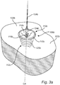
Fig. 3a is a perspective detail view of another anchor element of the suspended ceiling system ofFig. 1 . -
Fig. 3b is a cross sectional view of the anchor element ofFig. 3a . -
Fig. 4 is a cross sectional detail view of the suspended ceiling system ofFig. 1 . -
Fig. 5 is a perspective view of a suspended baffle. -
Fig. 6 is a perspective view of a suspended wall panel. - The present inventive concept will now be described more fully hereinafter with reference to the accompanying drawings, in which preferred variants of the inventive concept are shown. This inventive concept may, however, be embodied in many different forms and should not be construed as limited to the variants set forth herein; rather, these variants are provided for thoroughness and completeness, and fully convey the scope of the inventive concept to the skilled person. Like reference numerals refer to like elements throughout the description.
- Initially a tile system in form of a suspended
ceiling system 100 will be described with reference toFigs. 1-4 . Following the description of the suspended ceiling system 100 abaffle system 200 will be described with reference toFig. 5 and a tile system in form of awall panel system 300 will be described with reference toFig. 6 . -
Fig. 1 is a schematic perspective view of conceptually depicting atile system 100 in form of a suspendedceiling system 100. For reasons of simplicity there are six planar tiles or objects in form ofceiling tiles 102a-f illustrated inFig. 1 . It is however to be understood that any number of ceiling tiles may be used according to the present inventive concept. Eachceiling tile 102a-f has a first major surface intended to face an interior of a room and an opposing second major surface. Further, eachceiling tile 102a-e has four side edge surfaces 109a-e extending between the respective first and second major surfaces. However,ceiling tile 102f has a singleside edge surface 109f circumferencing theceiling tile 102f at an outer periphery thereof and extending between the first and second major surfaces. -
Fig 1 . Illustrates how theceiling tiles 102a-f, forming a suspended ceiling, are suspended from a structural ceiling of a building, not shown. - Each
ceiling tile 102a-f is suspended by means ofsuspension elements 104a-f, 104x in form of wires. Other relevant examples of suspension elements are a line, a cable, a cord, a thread, a rod, a string, a chain, a rope or a combination thereof. Theceiling tiles 102a-d are suspended using foursuspension elements 104a-d each.Ceiling tile 102e is suspended using fivesuspension elements 104e, whereasceiling tile 102f is suspended using threesuspension elements 104f. Eachsuspension elements 104a-f are attached to the ceiling tiles in corresponding attachment points. Each attachment point includes ananchor element 106a-f. -
Ceiling tile 102f is suspended belowceiling tile 102e, in the sense thatceiling tile 102f is located further below the structural ceiling and partially underceiling tile 102e.Ceiling tiles suspension element 104x, which is used for suspending bothceiling tile 102e andceiling tile 102f. The depictedsuspension element 104x is a wire likesuspension elements 104a-f. - The
ceiling tiles 102a-f, comprises compressed mineral fiber material. Suitable examples of compressed mineral fiber material are glass wool, mineral wool and rock wool, however other materials are also conceivable without departing from the scope of the inventive concept. Ceiling tiles comprising the exemplified materials are known to exhibit sound absorbing properties. - As can be seen in
Fig. 1 , theceiling tiles 102a-f are of different sizes and different shapes.Ceiling tiles 102a-d are all of a square shape and are of the same size.Ceiling tile 102e on the other hand is larger compared toceiling tiles 102a-d. Alsoceiling tile 102d is in the form of a square.Ceiling tile 102f on the other hand is exhibiting a circular shape. As is evident, the size of and shape of theceiling tiles 102a-f may be altered into any size and shape without departing from the scope of the present inventive concept. Also the arrangement in terms of how therespective ceiling tiles 102a-f are suspended with respect to each other and the room in which they are present may be altered to suit the needs presently at hand. For instance, theceiling tiles 102a-f may be arranged at different heights and/or may be inclined relative each other. - In
Fig. 1 theceiling tiles 102a-f are illustrated as being free hanging, meaning that therespective ceiling tiles 102a-f are not in contact with each other. It is however possible to arrange theceiling tiles 102a-f such that therespective ceiling tiles 102a-f are in contact with neighboring ceiling tiles or some of the neighboring ceiling tiles. - Further, the
ceiling tiles 102a-f may be provided with a layer, not shown, on the side facing the interior of the room in which theceiling tiles 102a-f are suspended. The layer may in turn be provided with decorative elements such a paint, a print, a sticker or similar. In other words, the appearance of theceiling tiles 102a-f may be altered to suit the needs of a particular installation. - It will now be described in greater detail, with reference to
Fig 2a and2b , howsuspension element 104a is used to suspendceiling tile 102a by being connected to theceiling tile 102a by means ofanchor element 106a. Also the design of theanchor element 106a will be described in greater detail. Although the below description will be made with reference toceiling tile 102a,suspension element 104a andanchor element 106a, the below description is equally valid for any of theceiling tiles 102a-f, any of thesuspension elements 104a-f and any of theanchor elements 106a-f. - In
Figs. 2a and2b it is depicted howanchor element 106a is screwed intoceiling tile 102a, at the secondmajor surface 108a thereof. The firstmajor surface 107a is facing the interior of the room in which theceiling tile 102a is suspended. Theanchor element 106a is screwed into theceiling tile 102a such that theanchor element 106a becomes completely recessed in theceiling tile 102a. As is depicted, the secondmajor surface 108a is deflected at the location of theanchor element 106a, such that theanchor element 106a becomes completely recessed in theceiling tile 102a. - The depicted
anchor element 106a ofFigs. 2a and2b comprises ahead portion 110a and a threadedportion 112a. Thehead portion 110a is located above the threadedportion 112a. In the depictedanchor element 106a thehead portion 110a and the threadedportion 112a are integrally formed by being molded form metal. The head portion of the depictedanchor element 106a has a diameter of 37 mm. However, diameters in the range of 10-100 mm are generally feasible depending e.g. on the thickness and weight of theceiling tile 102a to be suspended. - The
head portion 110a includes anopen cavity 114a. Thecavity 114a is facing thetop surface 116a of thehead portion 110a. In other words, thecavity 114a is open in the sense that it is accessible form thetop surface 116a of thehead portion 110a. Thecavity 114a is formed by molded separation walls. Thecavity 114a is elongated and has a conical cross section along a longitudinal direction thereof. Thecavity 114a has a rectangular cross section across the longitudinal direction thereof. - An
engagement member 118a is arranged in thecavity 114a. An upper surface of theengagement member 118a is flush with thetop surface 116a. In the depictedanchor element 106a, theengagement member 118a is formed as a bar structure traversing thecavity 114a. In other words, the bar structure forming theengagement member 118a is extending across thecavity 114a. Theengagement member 118a is integrally formed with thehead portion 110a and the threadedportion 112a of theanchor element 106a. - The
engagement member 118a is laterally displaced with respect to the central axis CA of theanchor element 106a. This means in practice that thecavity 114a is accessible by means of two differently sized openings, located on either side of theengagement member 118a. - The threaded
portion 112a includes athread 120a. The thread of the depictedanchor element 106a is conical in the sense that its radius increases towards thehead portion 110a. The depictedthread 120a has a radius of 10 mm at its starting point and a radius of 16.6 mm at its end point, i.e. where thethread 120a terminates at thehead portion 110a. The pitch of the thread 120 is 6 mm. This means that the separation between consecutive turns of thethread 120a is 6 mm. Examples of feasible pitches are between 4 and 10 mm. The periphery of thethread 120a is preferably relatively speaking sharp so as to cut through the material of theceiling tile 102a, thereby facilitating its insertion into theceiling tile 102a. Also the conical demolding of thethread 120a facilitates its insertion into the material of theceiling tile 102a. - The
anchor element 106a is provided with a throughhole 122a extending along the central axis CA of theanchor element 106a. The narrower bottom portion of the throughhole 122a has a diameter of 2.3 mm, thereby facilitating insertion of a wire or similar having a diameter of 2.0 mm. A central portion of the throughhole 122a may e.g. be provided with an internal M4 thread. The function of the throughhole 122a will be discussed in greater detail below with reference toFig. 4 . - As is seen in
Figs. 2a and2b , thesuspension element 104a includes ahook element 124a provided at the end of thesuspension element 104a. Thehook element 124a is hooked around theengagement member 118a, thereby providing a releasable coupling between theanchor element 106a and thesuspension element 104a. In other words, thehook element 124a may be coupled and de-coupled from theengagement member 118a. Thehook element 124a is provided with a spring-loadedsafety bar 126a in order to prevent undesired and unintentional de-coupling of thehook element 124a from theengagement member 118a. The spring-loadedsafety bar 126a enables a simple snap-in engagement where the spring-loadedsafety bar 126a does not have to be actuated separately. - The
hook element 124a is shaped such that the body of thesuspension element 104a aligns with the central axis CA of theanchor element 106a. In other words, the shape of thehook element 124a compensates for the lateral displacement of theengagement member 118a with respect to a central axis CA of theanchor element 106a, such that the body of thesuspension element 104a becomes aligned with the central axis CA of the anchor element. It is to be understood that the lateral displacement of theengagement member 118a and the shape of thehook element 124a may be varied while still resulting in that the body of thesuspension element 104a becomes aligned with the central axis CA of theanchor element 106a. It is also to be understood that the body of thesuspension element 104a may be offset with respect to the central axis CA of theanchor element 106a without departing from the present inventive concept. - The depicted
anchor element 106a has a length, i.e. an extension along the central axis CA of theanchor element 106a, of 32.5 mm. Typical feasible lengths are between 10-150 mm, depending e.g. on the thickness of the ceiling tiles to be suspended. - It will now be described in greater detail, with reference to
Fig 3a and3b , howsuspension element 104b is used to suspendceiling tile 102b by being connected to theceiling tile 102b by means ofanchor element 106b. Also the design of theanchor element 106b which is different from theanchor element 106a ofFigs. 2a and2b will be described in greater detail. Although the below description will be made with reference toceiling tile 102b,suspension element 104b andanchor element 106b, the below description is equally valid for any of theceiling tiles 102a-f, any of thesuspension elements 104a-f and any of theanchor elements 106a-f. - In
Figs. 3a and3b it is depicted howanchor element 106b is screwed intoceiling tile 102b, at the secondmajor surface 108b thereof. Theanchor element 106b is screwed into theceiling tile 102b such that theanchor element 106b becomes recessed in theceiling tile 102b. As is depicted, the secondmajor surface 108b is flat, i.e. not deflected, at the location of theanchor element 106b. Hence, a top portion of theanchor element 106b protrudes slightly above the secondmajor surface 108b. - The depicted
anchor element 106b ofFigs. 3a and3b comprises ahead portion 110b and a threadedportion 112b, like theanchor element 106a ofFigs. 2a and2b . Thehead portion 110b is located above the threadedportion 112b. In the depictedanchor element 106b thehead portion 110b and the threadedportion 112b are integrally formed by being molded form metal. The head portion of the depictedanchor element 106b has a diameter of 37 mm. However, diameters in the range of 10-100 mm are generally feasible depending e.g. on the thickness and weight of the ceiling tile to be suspended, as discussed above. - The
head portion 110b includes anopen cavity 114b. Thecavity 114b is facing atop surface 116b of thehead portion 110b. Thecavity 114b is formed by molded separation walls. Thecavity 114b is rotationally symmetric and has a conical cross section. - An
engagement member 118b is arranged in thecavity 114b. An uppermost portion of theengagement member 118b is located below thetop surface 116b of theanchor element 106b. Hence, theengagement member 118b is completely arranged within thecavity 114b. In the depictedanchor element 106b, theengagement member 118b is formed as a loop structure arranged in thecavity 114b of thehead portion 110b. Theengagement member 118b is formed separately from thehead portion 110b and the threadedportion 112b of theanchor element 106b, and subsequently fastened within thecavity 114b of thehead portion 110b. The depictedengagement member 118b is formed as a closed loop which is screwed into a threaded hole provided in therecess 114b. Theengagement member 118b, i.e. the loop, may however be fastened within thecavity 114b using other fastening techniques, such as soldering, welding or gluing to give a few non-limiting examples. Also other shapes of theengagement member 118b are feasible. For instance, theengagement member 118b may be formed as an open loop or like a hook. - The
engagement member 118b is aligned with respect to the central axis CA of theanchor element 106b. - The threaded
portion 112b includes athread 120b. Thethread 120b is similar to thethread 120a ofFigs. 2a and2b described above, why thethread 120b will not be described in greater detail to avoid undue repetition. - As is seen in
Figs. 3a and3b , thesuspension element 104b includes ahook element 124b provided at an end of thesuspension element 104b. Thehook element 124b is hooked around theengagement member 118b, thereby providing a releasable coupling between theanchor element 106b and thesuspension element 104b. In other words, thehook element 124b may be coupled and de-coupled from theengagement member 118b just like thehook element 124a ofFigs. 2a and2b . Thehook element 124b is formed as an open hook void of any safety bar or similar. - The
hook element 124b is shaped such that the body of thesuspension element 104b aligns with the central axis CA of theanchor element 106b. This means that thehook element 124b is aligned with the central axis CA of theanchor element 106b when hooking theengagement member 118b. It is however to be understood that thehook element 124b may be differently shaped so as to e.g. provide a lateral displacement with respect to the central axis CA of theanchor element 106b. - The length of the
anchor element 106b is similar to the length of theanchor element 106a ofFigs. 2a and2b , as described above. - Now referring to
Fig. 4 , here it is conceptually depicted in greater detail howceiling tiles common suspension element 104x, andrespective anchor elements -
Anchor element 106e used for suspendingceiling tile 102e is of the same type asanchor element 102a described above in relation toFigs. 2a and2b . Hence,anchor element 102e will not be described in greater detail to avoid undue repetition. -
Anchor element 106f used for suspendingceiling tile 102f is similar toanchor element 102a described above in relation toFigs. 2a and2b . However, thehead portion 110f is formed differently as compared to thehead portions head portion 110f ofanchor element 106f has a rotationally symmetric underside meaning that theopen cavity 114f is formed in an otherwise rotationallysymmetric head portion 110f as opposed to thehead portions open cavities anchor element 106f has a corresponding function to theanchor elements - As can be seen in
Fig. 4 , thesuspension element 104x is fed through the throughhole 122e ofanchor element 106e and theceiling tile 102e. Hence, thesuspension element r 104x exitsceiling tile 102e on its firstmajor surface 107e, i.e. the surface facing the interior of the room in which theceiling tile 102e is suspended. - The
suspension element 104x is fed through a through hole of the hook element 124e, meaning that thesuspension element 104x continues below or after the hook element 124e, as illustrated inFig. 4 . The hook element 124e is similar to thehook element 124a and will not be described in greater detail to avoid undue repetition. The hook element 124e hooks theengagement member 118e ofanchor element 106e. - A
hook element 124f is provided at the end ofsuspension element 104x, as illustrated inFig. 4 . Also hookelement 124f is similar to thehook element 124a and will not be described in greater detail to avoid undue repetition. Thehook element 124f hooks theengagement member 118f ofanchor element 106f. - By this arrangement,
ceiling tile 102e is suspended aboveceiling tile 102f using thecommon suspension element 104x, as described above. It is to be understood that three or more ceiling tiles may be suspended after each other in a vertical direction using a common suspension element r as described above. - Now referring to
Fig. 5 , here is conceptually depicted atile system 200 in form of abaffle system 200. For reasons of simplicity there is a single planar tile in form abaffle 202a illustrated inFig. 5 . It is however to be understood that any number ofbaffles 202a may be used according to the present inventive concept. Thebaffle 202a has a firstmajor surface 207a and an opposing second major surface. Further, thebaffle 202a has four side edge surfaces 209a extending between the respective first 207a and second major surfaces. - The
baffle 202a, comprises compressed mineral fiber material. Suitable examples of compressed mineral fiber material are glass wool, mineral wool and rock wool, however other materials are also conceivable without departing from the scope of the inventive concept. Baffles comprising the exemplified materials are known to exhibit sound absorbing properties. - The
baffle 202a is suspended by means of twosuspension elements 204a in form of wires. Other relevant examples of suspension elements are a line, a cable, a cord, a thread, a rod, a string, a chain, a rope or a combination thereof. Eachsuspension element 204a includes ahook element 224a provided at the end of thesuspension elements 204a. Eachsuspension element 204a is attached to thebaffle 202a in corresponding attachment points. Each attachment point includes ananchor element 206a. Theanchor elements 206a and thehook elements 124a are of the type described above in conjunction withFigs. 2a and2b . Accordingly, theanchor elements 206a and thehook elements 124a will not be described in detail below to avoid undue repetition. - The
anchor elements 206a are screwed into one of the side edge surfaces 209a of the baffle 202a. By screwing theanchor elements 206a into one of theside edge surfaces 209a the baffle 202a may be vertically suspended as illustrated inFig. 5 . - Now referring to
Fig. 6 , here is conceptually depicted atile system 300 in form of awall panel system 300. For reasons of simplicity there is a single planar tile in form awall panel 302a illustrated inFig. 6 . It is however to be understood that any number ofwall panels 302a may be used according to the present inventive concept. Thewall panel 302a has a first major surface and an opposing secondmajor surface 308a. Further, thewall panel 302a has four side edge surfaces 309a extending between the respective first and second 308a major surfaces. - The
wall panel 302a, comprises compressed mineral fiber material. Suitable examples of compressed mineral fiber material are glass wool, mineral wool and rock wool, however other materials are also conceivable without departing from the scope of the inventive concept. Wall panels comprising the exemplified materials are known to exhibit sound absorbing properties. - The
wall panel 302a is suspended by means of twosuspension elements 304a in form of wall mountedhooks 304a. Eachsuspension element 304a includes a hook element. Eachsuspension element 304a is attached to thewall panel 302a in corresponding attachment points. Each attachment point includes ananchor element 306a. The respective hook elements of thesuspension elements 304a are configured to engage the respective engagement members of the anchor elements 306a.Theanchor elements 306a are of the type described above in conjunction withFigs. 2a and2b . Accordingly, theanchor elements 306a will not be described in detail below to avoid undue repetition. - The
anchor elements 306a are screwed into the secondmajor surface 308a of thewall panel 302a. By screwing theanchor elements 306a into secondmajor surface 308a of thewall panel 302a, thewall panel 302a may be vertically suspended by means of the wall mountedhooks 304a as illustrated inFig. 6 . - As is understood, the respective types of
anchor elements 106a-f described above may be interchanged with each other to suit specific installation needs. Hence, a suspended ceiling may include a plurality of types ofanchor elements 106a-f. Similarly, a suspended ceiling may include a single type ofanchor elements 106a-f. Also the type ofsuspension elements 104a-f, 104x may be varied within a suspended ceiling or a single type ofsuspension element 104a-f, 104x may be used. Theanchor elements 106a-f described may advantageously be used to fasten or suspend vertically arranged panels or tiles, such assound absorbing baffles 202a orwall panels 302a, as described above. Also, atile system ceiling tiles 102a-f, baffles 202a andwall panels 302a. In other words, asingle tile system ceiling tiles 102a-f and a number ofbaffles 202a to give an example. - It will be appreciated that the present inventive concept is not limited to the variants shown. Several modifications and variations are thus conceivable within the scope of the invention which thus is exclusively defined by the appended claims.
Claims (15)
- A tile system (100, 200, 300) comprising:an absorber tile element (102a-f, 202a, 302a) comprising compressed mineral fiber material and having a first major surface (107a-b, 107e-f, 207a), an opposing second major surface (108a-b, 108e-f, 308a), and at least one side edge surface (109a-f, 209a, 309a) extending between the first major surface (107a-b, 107e-f, 207a) and the second major surface (108a-b, 108e-f, 308a),an anchor element (106a-f, 206a, 306a) associated with one of the first major surface (107a-b, 107e-f, 207a) and the second major surface (108a-b, 108e-f, 307a) or one of the at least one side edge surfaces (109a-f, 209a, 309a) of the absorber tile element (102a-f, 202a, 302a), anda suspension element (104a-104f, 104x, 204a, 304a) releasably coupled to the anchor element (106a-f, 206a, 306a) for suspension of the absorber tile element (102a-f, 202a, 302a),wherein the anchor element (106a-f, 206a, 306a) comprises a head portion (110a-b, 110e-f) and a threaded portion (112a-b, 112e-f),the head portion (110a-b, 110e-f) defining an open cavity (114a-b, 114e-f) facing a top surface (116a-b, 116e-f) of the head portion (110a-b, 110e-f), wherein an engagement member (118a-b, 118e-f) is arranged in the cavity (114a-b, 114e-f),the threaded portion (112a-b, 112e-f) being threaded into the absorber tile element (102a-f, 202a, 302a) from the surface (107a-b, 107e-f; 108a-b, 108e-f; 209a; 309a) associated with the anchor element (106a-f, 206a, 306a) such that the head portion (110a-b, 110e-f) becomes recessed in the absorber tile element (102a-f, 202a, 302a), andwherein the suspension element (104a-104f, 104x, 204a, 304a) comprises a hook element (124a-b, 124e-f) hooking the engagement member (118a-b, 118e-f) of the anchor element (106a-f, 206a, 306a).
- The tile system (100, 200, 300) according to claim 1, wherein the engagement member (118a, 118e-f) comprises an elongated bar structure traversing the cavity (114a, 114e-f) of the head portion (110a, 110e-f).
- The tile system (100, 200, 300) according to claim 1, wherein the engagement member (118b) comprises a loop structure arranged in the cavity (114b) of the head portion (110b).
- The tile system (100, 200, 300) according to claim 1, wherein the engagement member (118a-b, 118e-f) is laterally displaced with respect to a central axis (CA) of the anchor element (106a-f, 206a, 306a).
- The tile system (100, 200, 300) according to claim 1, wherein the engagement member (118a-b, 118e-f) and/or the hook element (124a-b, 124e-f) is/are configured to align a body of the suspension element (104a-104f, 104x, 204a) with a central axis (CA) of the anchor element (106a-f).
- The tile system (100, 200, 300) according to claim 1, wherein the anchor element (106a, 106c-f, 206a, 306a) is provided with a through hole (122a, 122e-f) extending along a central axis (CA) of the anchor element (106a, 106c-f).
- The tile system (100, 200, 300) according to claim 1, wherein the anchor element (106a-f, 206a, 306a) has an extension in the interval of 10-150 mm, preferably 15-100 mm, along a central axis (CA) thereof.
- The tile system (100, 200, 300) according to claim 1, wherein the anchor element (106a-f, 206a, 306a) has an extension in the interval of 10-100 mm, preferably 15-60 mm, in a direction transverse to a central axis (CA) thereof.
- The tile system according to claim 1, wherein the threaded portion (112a-b, 112e-f) of the anchor element (106a-f, 206a, 306a) comprises threads (120a-b, 120e-f) having a pitch in the interval of 4-10 mm, preferably 5-7 mm.
- An absorber tile element (102a-f, 202a, 302a) comprising compressed mineral fiber material and having a first major surface (107a-b, 107e-f, 207a), an opposing second major surface (108a-b, 108e-f, 308a), and at least one side edge surface (109a-f, 209a, 309a) extending between the first major surface (107a-b, 107e-f, 207a) and the second major surface (108a-b, 108e-f, 308a),
an anchor element (106a-f) associated with one of the first major surface (107a-b, 107e-f, 207a) and the second major surface (108a-b, 108e-f, 308a) or one of the at least one side edge surfaces (109a-f, 209a, 309a) of the absorber tile element (102a-f, 202a, 302a),
wherein the anchor element (106a-f, 206a, 306a) comprises a head portion (110a-b, 110e-f) and a threaded portion (112a-b, 112e-f),the head portion (110a-b, 110e-f) defining an open cavity (114a-b, 114e-f) facing a top surface (116a-b, 116e-f) of the head portion (110a-b, 110e-f), wherein an engagement member (118a-b, 118e-f) is arranged in the cavity (114a-b, 114e-f), and configured for engagement with a hook element (124a-b, 124e-f),the threaded portion (112a-b, 112e-f) being threaded into the absorber tile element (102a-f) from the surface (107a-b, 107e-f; 108a-b, 108e-f; 209a; 309a) associated with the anchor element (106a-f, 206a, 306a) such that the head portion (110a-b, 110e-f) becomes recessed in the absorber tile element (102a-f, 202a, 302a). - The absorber tile element (102a-f, 202a, 302a) according to claim 10, wherein the engagement member (118a, 118e-f) comprises an elongated bar structure traversing the cavity (114a, 114e-f) of the head portion (110a, 110e-f).
- The absorber tile element (102a-f, 202a, 302a) according to claim 10, wherein the engagement member (118b) comprises a loop structure arranged in the cavity (114b) of the head portion (110b).
- The absorber tile element (102a-f, 202a, 302a) according to claim 10, wherein the engagement member (118a-b, 118e-f) is laterally displaced with respect to a central axis (CA) of the anchor element (106a-f, 206a, 306a).
- The absorber tile element (102a-f, 202a, 302a) according to claim 10, wherein the anchor element (106a, 106c-f, 206a, 306a) is provided with a through hole (122a, 122e-f) extending along a central axis (CA) of the anchor element (106a, 106c-f, 206a, 306a).
- The absorber tile element (102a-f, 202a, 302a) according to claim 10, wherein the anchor element (106a-f, 206a, 306a) has an extension in the interval of 10-150 mm, preferably 15-100 mm, along a central axis (CA) thereof, wherein the anchor element (106a-f, 206a, 306a) has an extension in the interval of 10-100 mm, preferably 15-60 mm, in a direction transverse to the central axis (CA), and wherein the threaded portion (112a-b, 112e-f) of the anchor element (106a-f, 206a, 306a) comprises threads (120a-b, 120e-f) having a pitch in the interval of 4-10 mm, preferably 5-7 mm.
Priority Applications (4)
| Application Number | Priority Date | Filing Date | Title |
|---|---|---|---|
| EP18178271.5A EP3584382B1 (en) | 2018-06-18 | 2018-06-18 | Suspended tile system and absorber tile element |
| US16/973,629 US11274442B2 (en) | 2018-06-18 | 2019-06-11 | Suspended tile system and absorber tile element |
| CA3103184A CA3103184C (en) | 2018-06-18 | 2019-06-11 | Suspended tile system and absorber tile element |
| PCT/EP2019/065099 WO2019243103A1 (en) | 2018-06-18 | 2019-06-11 | Suspended tile system and absorber tile element |
Applications Claiming Priority (1)
| Application Number | Priority Date | Filing Date | Title |
|---|---|---|---|
| EP18178271.5A EP3584382B1 (en) | 2018-06-18 | 2018-06-18 | Suspended tile system and absorber tile element |
Publications (3)
| Publication Number | Publication Date |
|---|---|
| EP3584382A1 true EP3584382A1 (en) | 2019-12-25 |
| EP3584382C0 EP3584382C0 (en) | 2024-07-03 |
| EP3584382B1 EP3584382B1 (en) | 2024-07-03 |
Family
ID=62705490
Family Applications (1)
| Application Number | Title | Priority Date | Filing Date |
|---|---|---|---|
| EP18178271.5A Active EP3584382B1 (en) | 2018-06-18 | 2018-06-18 | Suspended tile system and absorber tile element |
Country Status (4)
| Country | Link |
|---|---|
| US (1) | US11274442B2 (en) |
| EP (1) | EP3584382B1 (en) |
| CA (1) | CA3103184C (en) |
| WO (1) | WO2019243103A1 (en) |
Cited By (3)
| Publication number | Priority date | Publication date | Assignee | Title |
|---|---|---|---|---|
| CN111809787A (en) * | 2020-07-31 | 2020-10-23 | 杭州航顶装饰材料有限公司 | But angle regulation's aluminum honeycomb panel hangs and connects structure |
| EP4112836A1 (en) * | 2021-07-01 | 2023-01-04 | Saint-Gobain Ecophon AB | Absorber tile element and tile system |
| EP4187108A1 (en) * | 2021-11-29 | 2023-05-31 | Saint-Gobain Ecophon AB | Tile element and tile system |
Families Citing this family (3)
| Publication number | Priority date | Publication date | Assignee | Title |
|---|---|---|---|---|
| GB201701736D0 (en) * | 2017-02-02 | 2017-03-22 | Gripple Ltd | Securing assembly |
| JP7813114B2 (en) * | 2021-09-24 | 2026-02-12 | 株式会社淺沼組 | suspended ceiling |
| US11524190B1 (en) * | 2022-05-13 | 2022-12-13 | Ilija Rokvic | Smoke baffle assembly and method of installation |
Citations (3)
| Publication number | Priority date | Publication date | Assignee | Title |
|---|---|---|---|---|
| EP2546430A1 (en) * | 2011-07-12 | 2013-01-16 | Saint-Gobain Ecophon AB | A suspended ceiling system and a method for suspending such a ceiling system |
| EP2884019A1 (en) * | 2013-12-13 | 2015-06-17 | Saint-Gobain Ecophon AB | Suspended ceiling system and method |
| EP2902559A1 (en) * | 2014-01-30 | 2015-08-05 | Saint-Gobain Ecophon AB | A suspended ceiling system and a method for mounting a suspended ceiling |
Family Cites Families (10)
| Publication number | Priority date | Publication date | Assignee | Title |
|---|---|---|---|---|
| US3004644A (en) * | 1959-01-30 | 1961-10-17 | Gen Motors Corp | Adjustable hanger |
| US3389524A (en) * | 1965-03-05 | 1968-06-25 | Weber Robert | Two holer support |
| DE2233933C3 (en) * | 1972-07-11 | 1981-04-09 | Dr.h.c. Artur 7244 Waldachtal Fischer | Suspension device for suspended ceilings, pipes and the like. |
| FR2634240B1 (en) * | 1988-07-13 | 1993-04-16 | Sari | PROCESS FOR PRODUCING A SUSPENDED CEILING; SUSPENDED CEILING LIKELY TO BE REALIZED BY THIS PROCESS; ANCHORING MEANS FOR THE IMPLEMENTATION OF THIS PROCESS |
| FR2642780B1 (en) * | 1989-01-16 | 1991-05-24 | Rapid Sa | DEVICE FOR FIXING PANELS FORMING, FOR EXAMPLE, CEILING TILES |
| CA2036955C (en) * | 1991-02-25 | 1995-03-21 | Raymond G. Faucher | Hanger nail for suspended ceiling |
| US20050211500A1 (en) * | 2004-03-26 | 2005-09-29 | Wendt Alan C | Fibrous faced ceiling panel |
| US20120317915A1 (en) * | 2011-06-16 | 2012-12-20 | Chicago Metallic Corporation | Self-Hanging Notched Ceiling Tile |
| FR2980498B1 (en) * | 2011-09-28 | 2015-05-01 | Ober | COMPLETE FIXING DEVICE FOR SUSPENDED CEILING WHICH SUSPENDS SLABS IN INCLINED POSITION OR / AND ON DIFFERENT LEVELS |
| US9556614B2 (en) * | 2015-05-13 | 2017-01-31 | Awi Licensing Llc | Mounting apparatus for suspended ceiling system |
-
2018
- 2018-06-18 EP EP18178271.5A patent/EP3584382B1/en active Active
-
2019
- 2019-06-11 US US16/973,629 patent/US11274442B2/en active Active
- 2019-06-11 WO PCT/EP2019/065099 patent/WO2019243103A1/en not_active Ceased
- 2019-06-11 CA CA3103184A patent/CA3103184C/en active Active
Patent Citations (3)
| Publication number | Priority date | Publication date | Assignee | Title |
|---|---|---|---|---|
| EP2546430A1 (en) * | 2011-07-12 | 2013-01-16 | Saint-Gobain Ecophon AB | A suspended ceiling system and a method for suspending such a ceiling system |
| EP2884019A1 (en) * | 2013-12-13 | 2015-06-17 | Saint-Gobain Ecophon AB | Suspended ceiling system and method |
| EP2902559A1 (en) * | 2014-01-30 | 2015-08-05 | Saint-Gobain Ecophon AB | A suspended ceiling system and a method for mounting a suspended ceiling |
Cited By (5)
| Publication number | Priority date | Publication date | Assignee | Title |
|---|---|---|---|---|
| CN111809787A (en) * | 2020-07-31 | 2020-10-23 | 杭州航顶装饰材料有限公司 | But angle regulation's aluminum honeycomb panel hangs and connects structure |
| EP4112836A1 (en) * | 2021-07-01 | 2023-01-04 | Saint-Gobain Ecophon AB | Absorber tile element and tile system |
| WO2023274735A1 (en) | 2021-07-01 | 2023-01-05 | Saint-Gobain Ecophon Ab | Absorber tile element and tile system |
| EP4187108A1 (en) * | 2021-11-29 | 2023-05-31 | Saint-Gobain Ecophon AB | Tile element and tile system |
| WO2023094036A1 (en) * | 2021-11-29 | 2023-06-01 | Saint-Gobain Ecophon Ab | Tile element and tile system |
Also Published As
| Publication number | Publication date |
|---|---|
| US20210164225A1 (en) | 2021-06-03 |
| EP3584382C0 (en) | 2024-07-03 |
| CA3103184A1 (en) | 2019-12-26 |
| EP3584382B1 (en) | 2024-07-03 |
| WO2019243103A1 (en) | 2019-12-26 |
| US11274442B2 (en) | 2022-03-15 |
| CA3103184C (en) | 2023-03-28 |
Similar Documents
| Publication | Publication Date | Title |
|---|---|---|
| CA3103184C (en) | Suspended tile system and absorber tile element | |
| US11952776B2 (en) | Suspended ceiling system, securing members, and process of installing a suspended ceiling system | |
| US9909312B2 (en) | Free span ceiling grid system | |
| EP2884019B1 (en) | Suspended ceiling system and method | |
| US20070246631A1 (en) | Automatic leveling suspension system for luminaires | |
| CN208832687U (en) | Ceiling Embedded Air Conditioner | |
| ES3039311T3 (en) | A system for mounting a suspended ceiling | |
| EP2546430B1 (en) | A suspended ceiling system and a method for suspending such a ceiling system | |
| US11946250B2 (en) | Ceiling system and method of installation | |
| US20150240477A1 (en) | Apparatus for securing insulation panels to a supporting structure and ceiling support assembly incorporating the same | |
| JP2014185508A5 (en) | ||
| JP2014185508A (en) | Connection metal fitting | |
| EP4469642B1 (en) | A suspension system for an acoustic ceiling island platform and an acoustic ceiling island platform | |
| US20080047213A1 (en) | Suspended ceiling clip and method of use | |
| US8714506B2 (en) | Mounting assembly for electrical fixture | |
| US20250012078A1 (en) | Tile element and tile system | |
| RU2771308C2 (en) | Suspension system | |
| EP4112836B1 (en) | Absorber tile element and tile system | |
| JP6346744B2 (en) | Blindfold board and its construction method | |
| JPH078680Y2 (en) | System ceiling | |
| US20130056600A1 (en) | Blocking support hanger | |
| AU2006201389A1 (en) | Attachment System for a Suspended Ceiling | |
| JPH0544289A (en) | Decorated ceiling |
Legal Events
| Date | Code | Title | Description |
|---|---|---|---|
| PUAI | Public reference made under article 153(3) epc to a published international application that has entered the european phase |
Free format text: ORIGINAL CODE: 0009012 |
|
| STAA | Information on the status of an ep patent application or granted ep patent |
Free format text: STATUS: THE APPLICATION HAS BEEN PUBLISHED |
|
| AK | Designated contracting states |
Kind code of ref document: A1 Designated state(s): AL AT BE BG CH CY CZ DE DK EE ES FI FR GB GR HR HU IE IS IT LI LT LU LV MC MK MT NL NO PL PT RO RS SE SI SK SM TR |
|
| AX | Request for extension of the european patent |
Extension state: BA ME |
|
| STAA | Information on the status of an ep patent application or granted ep patent |
Free format text: STATUS: REQUEST FOR EXAMINATION WAS MADE |
|
| 17P | Request for examination filed |
Effective date: 20200408 |
|
| RBV | Designated contracting states (corrected) |
Designated state(s): AL AT BE BG CH CY CZ DE DK EE ES FI FR GB GR HR HU IE IS IT LI LT LU LV MC MK MT NL NO PL PT RO RS SE SI SK SM TR |
|
| STAA | Information on the status of an ep patent application or granted ep patent |
Free format text: STATUS: EXAMINATION IS IN PROGRESS |
|
| 17Q | First examination report despatched |
Effective date: 20220516 |
|
| GRAP | Despatch of communication of intention to grant a patent |
Free format text: ORIGINAL CODE: EPIDOSNIGR1 |
|
| STAA | Information on the status of an ep patent application or granted ep patent |
Free format text: STATUS: GRANT OF PATENT IS INTENDED |
|
| INTG | Intention to grant announced |
Effective date: 20240208 |
|
| GRAS | Grant fee paid |
Free format text: ORIGINAL CODE: EPIDOSNIGR3 |
|
| GRAA | (expected) grant |
Free format text: ORIGINAL CODE: 0009210 |
|
| STAA | Information on the status of an ep patent application or granted ep patent |
Free format text: STATUS: THE PATENT HAS BEEN GRANTED |
|
| AK | Designated contracting states |
Kind code of ref document: B1 Designated state(s): AL AT BE BG CH CY CZ DE DK EE ES FI FR GB GR HR HU IE IS IT LI LT LU LV MC MK MT NL NO PL PT RO RS SE SI SK SM TR |
|
| REG | Reference to a national code |
Ref country code: CH Ref legal event code: EP |
|
| REG | Reference to a national code |
Ref country code: DE Ref legal event code: R096 Ref document number: 602018071215 Country of ref document: DE |
|
| U01 | Request for unitary effect filed |
Effective date: 20240703 |
|
| U07 | Unitary effect registered |
Designated state(s): AT BE BG DE DK EE FI FR IT LT LU LV MT NL PT SE SI Effective date: 20240711 |
|
| PG25 | Lapsed in a contracting state [announced via postgrant information from national office to epo] |
Ref country code: NO Free format text: LAPSE BECAUSE OF FAILURE TO SUBMIT A TRANSLATION OF THE DESCRIPTION OR TO PAY THE FEE WITHIN THE PRESCRIBED TIME-LIMIT Effective date: 20241003 |
|
| PG25 | Lapsed in a contracting state [announced via postgrant information from national office to epo] |
Ref country code: PL Free format text: LAPSE BECAUSE OF FAILURE TO SUBMIT A TRANSLATION OF THE DESCRIPTION OR TO PAY THE FEE WITHIN THE PRESCRIBED TIME-LIMIT Effective date: 20240703 Ref country code: GR Free format text: LAPSE BECAUSE OF FAILURE TO SUBMIT A TRANSLATION OF THE DESCRIPTION OR TO PAY THE FEE WITHIN THE PRESCRIBED TIME-LIMIT Effective date: 20241004 |
|
| PG25 | Lapsed in a contracting state [announced via postgrant information from national office to epo] |
Ref country code: IS Free format text: LAPSE BECAUSE OF FAILURE TO SUBMIT A TRANSLATION OF THE DESCRIPTION OR TO PAY THE FEE WITHIN THE PRESCRIBED TIME-LIMIT Effective date: 20241103 |
|
| PG25 | Lapsed in a contracting state [announced via postgrant information from national office to epo] |
Ref country code: HR Free format text: LAPSE BECAUSE OF FAILURE TO SUBMIT A TRANSLATION OF THE DESCRIPTION OR TO PAY THE FEE WITHIN THE PRESCRIBED TIME-LIMIT Effective date: 20240703 Ref country code: CZ Free format text: LAPSE BECAUSE OF FAILURE TO SUBMIT A TRANSLATION OF THE DESCRIPTION OR TO PAY THE FEE WITHIN THE PRESCRIBED TIME-LIMIT Effective date: 20240703 |
|
| PG25 | Lapsed in a contracting state [announced via postgrant information from national office to epo] |
Ref country code: RS Free format text: LAPSE BECAUSE OF FAILURE TO SUBMIT A TRANSLATION OF THE DESCRIPTION OR TO PAY THE FEE WITHIN THE PRESCRIBED TIME-LIMIT Effective date: 20241003 Ref country code: ES Free format text: LAPSE BECAUSE OF FAILURE TO SUBMIT A TRANSLATION OF THE DESCRIPTION OR TO PAY THE FEE WITHIN THE PRESCRIBED TIME-LIMIT Effective date: 20240703 |
|
| PG25 | Lapsed in a contracting state [announced via postgrant information from national office to epo] |
Ref country code: RS Free format text: LAPSE BECAUSE OF FAILURE TO SUBMIT A TRANSLATION OF THE DESCRIPTION OR TO PAY THE FEE WITHIN THE PRESCRIBED TIME-LIMIT Effective date: 20241003 Ref country code: PL Free format text: LAPSE BECAUSE OF FAILURE TO SUBMIT A TRANSLATION OF THE DESCRIPTION OR TO PAY THE FEE WITHIN THE PRESCRIBED TIME-LIMIT Effective date: 20240703 Ref country code: NO Free format text: LAPSE BECAUSE OF FAILURE TO SUBMIT A TRANSLATION OF THE DESCRIPTION OR TO PAY THE FEE WITHIN THE PRESCRIBED TIME-LIMIT Effective date: 20241003 Ref country code: IS Free format text: LAPSE BECAUSE OF FAILURE TO SUBMIT A TRANSLATION OF THE DESCRIPTION OR TO PAY THE FEE WITHIN THE PRESCRIBED TIME-LIMIT Effective date: 20241103 Ref country code: HR Free format text: LAPSE BECAUSE OF FAILURE TO SUBMIT A TRANSLATION OF THE DESCRIPTION OR TO PAY THE FEE WITHIN THE PRESCRIBED TIME-LIMIT Effective date: 20240703 Ref country code: GR Free format text: LAPSE BECAUSE OF FAILURE TO SUBMIT A TRANSLATION OF THE DESCRIPTION OR TO PAY THE FEE WITHIN THE PRESCRIBED TIME-LIMIT Effective date: 20241004 Ref country code: ES Free format text: LAPSE BECAUSE OF FAILURE TO SUBMIT A TRANSLATION OF THE DESCRIPTION OR TO PAY THE FEE WITHIN THE PRESCRIBED TIME-LIMIT Effective date: 20240703 Ref country code: CZ Free format text: LAPSE BECAUSE OF FAILURE TO SUBMIT A TRANSLATION OF THE DESCRIPTION OR TO PAY THE FEE WITHIN THE PRESCRIBED TIME-LIMIT Effective date: 20240703 |
|
| PG25 | Lapsed in a contracting state [announced via postgrant information from national office to epo] |
Ref country code: SM Free format text: LAPSE BECAUSE OF FAILURE TO SUBMIT A TRANSLATION OF THE DESCRIPTION OR TO PAY THE FEE WITHIN THE PRESCRIBED TIME-LIMIT Effective date: 20240703 |
|
| PG25 | Lapsed in a contracting state [announced via postgrant information from national office to epo] |
Ref country code: SK Free format text: LAPSE BECAUSE OF FAILURE TO SUBMIT A TRANSLATION OF THE DESCRIPTION OR TO PAY THE FEE WITHIN THE PRESCRIBED TIME-LIMIT Effective date: 20240703 |
|
| PLBE | No opposition filed within time limit |
Free format text: ORIGINAL CODE: 0009261 |
|
| STAA | Information on the status of an ep patent application or granted ep patent |
Free format text: STATUS: NO OPPOSITION FILED WITHIN TIME LIMIT |
|
| 26N | No opposition filed |
Effective date: 20250404 |
|
| U20 | Renewal fee for the european patent with unitary effect paid |
Year of fee payment: 8 Effective date: 20250516 |
|
| REG | Reference to a national code |
Ref country code: CH Ref legal event code: H13 Free format text: ST27 STATUS EVENT CODE: U-0-0-H10-H13 (AS PROVIDED BY THE NATIONAL OFFICE) Effective date: 20260127 |
|
| PG25 | Lapsed in a contracting state [announced via postgrant information from national office to epo] |
Ref country code: MC Free format text: LAPSE BECAUSE OF FAILURE TO SUBMIT A TRANSLATION OF THE DESCRIPTION OR TO PAY THE FEE WITHIN THE PRESCRIBED TIME-LIMIT Effective date: 20240703 |
|
| GBPC | Gb: european patent ceased through non-payment of renewal fee |
Effective date: 20250618 |
|
| PG25 | Lapsed in a contracting state [announced via postgrant information from national office to epo] |
Ref country code: GB Free format text: LAPSE BECAUSE OF NON-PAYMENT OF DUE FEES Effective date: 20250618 |
|
| PG25 | Lapsed in a contracting state [announced via postgrant information from national office to epo] |
Ref country code: IE Free format text: LAPSE BECAUSE OF NON-PAYMENT OF DUE FEES Effective date: 20250618 |
|
| PG25 | Lapsed in a contracting state [announced via postgrant information from national office to epo] |
Ref country code: RO Free format text: LAPSE BECAUSE OF FAILURE TO SUBMIT A TRANSLATION OF THE DESCRIPTION OR TO PAY THE FEE WITHIN THE PRESCRIBED TIME-LIMIT Effective date: 20240703 |
|
| PG25 | Lapsed in a contracting state [announced via postgrant information from national office to epo] |
Ref country code: CH Free format text: LAPSE BECAUSE OF NON-PAYMENT OF DUE FEES Effective date: 20250630 |
|
| U20 | Renewal fee for the european patent with unitary effect paid |
Year of fee payment: 9 Effective date: 20260625 |
|
| PG25 | Lapsed in a contracting state [announced via postgrant information from national office to epo] |
Ref country code: CY Free format text: LAPSE BECAUSE OF FAILURE TO SUBMIT A TRANSLATION OF THE DESCRIPTION OR TO PAY THE FEE WITHIN THE PRESCRIBED TIME-LIMIT Effective date: 20240703 |