EP3584036A1 - Part manufacturing system and part manufacturing method - Google Patents
Part manufacturing system and part manufacturing method Download PDFInfo
- Publication number
- EP3584036A1 EP3584036A1 EP18754120.6A EP18754120A EP3584036A1 EP 3584036 A1 EP3584036 A1 EP 3584036A1 EP 18754120 A EP18754120 A EP 18754120A EP 3584036 A1 EP3584036 A1 EP 3584036A1
- Authority
- EP
- European Patent Office
- Prior art keywords
- workpiece
- peening device
- shots
- section
- stringer
- Prior art date
- Legal status (The legal status is an assumption and is not a legal conclusion. Google has not performed a legal analysis and makes no representation as to the accuracy of the status listed.)
- Withdrawn
Links
Images




Classifications
-
- B—PERFORMING OPERATIONS; TRANSPORTING
- B24—GRINDING; POLISHING
- B24C—ABRASIVE OR RELATED BLASTING WITH PARTICULATE MATERIAL
- B24C1/00—Methods for use of abrasive blasting for producing particular effects; Use of auxiliary equipment in connection with such methods
- B24C1/10—Methods for use of abrasive blasting for producing particular effects; Use of auxiliary equipment in connection with such methods for compacting surfaces, e.g. shot-peening
-
- B—PERFORMING OPERATIONS; TRANSPORTING
- B24—GRINDING; POLISHING
- B24B—MACHINES, DEVICES, OR PROCESSES FOR GRINDING OR POLISHING; DRESSING OR CONDITIONING OF ABRADING SURFACES; FEEDING OF GRINDING, POLISHING, OR LAPPING AGENTS
- B24B27/00—Other grinding machines or devices
-
- B—PERFORMING OPERATIONS; TRANSPORTING
- B24—GRINDING; POLISHING
- B24C—ABRASIVE OR RELATED BLASTING WITH PARTICULATE MATERIAL
- B24C1/00—Methods for use of abrasive blasting for producing particular effects; Use of auxiliary equipment in connection with such methods
- B24C1/04—Methods for use of abrasive blasting for producing particular effects; Use of auxiliary equipment in connection with such methods for treating only selected parts of a surface, e.g. for carving stone or glass
-
- B—PERFORMING OPERATIONS; TRANSPORTING
- B24—GRINDING; POLISHING
- B24C—ABRASIVE OR RELATED BLASTING WITH PARTICULATE MATERIAL
- B24C3/00—Abrasive blasting machines or devices; Plants
- B24C3/32—Abrasive blasting machines or devices; Plants designed for abrasive blasting of particular work, e.g. the internal surfaces of cylinder blocks
-
- B—PERFORMING OPERATIONS; TRANSPORTING
- B25—HAND TOOLS; PORTABLE POWER-DRIVEN TOOLS; MANIPULATORS
- B25J—MANIPULATORS; CHAMBERS PROVIDED WITH MANIPULATION DEVICES
- B25J13/00—Controls for manipulators
- B25J13/08—Controls for manipulators by means of sensing devices, e.g. viewing or touching devices
-
- B—PERFORMING OPERATIONS; TRANSPORTING
- B64—AIRCRAFT; AVIATION; COSMONAUTICS
- B64F—GROUND OR AIRCRAFT-CARRIER-DECK INSTALLATIONS SPECIALLY ADAPTED FOR USE IN CONNECTION WITH AIRCRAFT; DESIGNING, MANUFACTURING, ASSEMBLING, CLEANING, MAINTAINING OR REPAIRING AIRCRAFT, NOT OTHERWISE PROVIDED FOR; HANDLING, TRANSPORTING, TESTING OR INSPECTING AIRCRAFT COMPONENTS, NOT OTHERWISE PROVIDED FOR
- B64F5/00—Designing, manufacturing, assembling, cleaning, maintaining or repairing aircraft, not otherwise provided for; Handling, transporting, testing or inspecting aircraft components, not otherwise provided for
- B64F5/10—Manufacturing or assembling aircraft, e.g. jigs therefor
-
- B—PERFORMING OPERATIONS; TRANSPORTING
- B64—AIRCRAFT; AVIATION; COSMONAUTICS
- B64C—AEROPLANES; HELICOPTERS
- B64C3/00—Wings
- B64C3/18—Spars; Ribs; Stringers
- B64C3/182—Stringers, longerons
-
- B—PERFORMING OPERATIONS; TRANSPORTING
- B64—AIRCRAFT; AVIATION; COSMONAUTICS
- B64C—AEROPLANES; HELICOPTERS
- B64C3/00—Wings
- B64C3/26—Construction, shape, or attachment of separate skins, e.g. panels
Definitions
- the present invention relates to a part manufacturing system and a part manufacturing method, and more particularly, to a part manufacturing system and a part manufacturing method for manufacturing an aircraft part which is manufactured by combining a skin, which is a plate-shaped member, and a stringer, which is an elongated member.
- an aircraft part such as a primary wing is formed by combining a skin, which is a plate-shamed member, and a stringer, which is an elongated member which is provided on the skin.
- the skin and the stringer are machined by a peen forming method into a shape having a predetermined curved surface.
- the peen forming method is a machining method of plastically deforming a workpiece by projecting steel balls (having a diameter of 5 mm, for example) called "shots" to the workpiece.
- peen forming is performed on an integrated member 50 including a flat plate-shaped skin 51 and stringers 52, which are provided on the skin 51, to plastically deform the integrated member 50.
- a saddle-shaped aircraft part 55 is formed, as shown in Fig. 9B .
- PTL1 mentioned below discloses a technology including a main machining step of forming, by projecting shots at a high speed to add a plastic strain, a surface of a flat plate section (primary wing outer plate) opposite a surface where a reinforcing section (stringer) is provided, and a corrective machining step, performed after the main machining step, of projecting shots at a high speed to the reinforcing section.
- the corrective machining step the plastic strain of a plate-shaped metal member in a direction along a longitudinal direction of the reinforcing section is corrected.
- a workpiece is continuously deformed while the shots (steel balls) are projected at a high speed to the workpiece, and positions that are hit by the shots are thereby changed, and thus, precise prediction of a deformation process is difficult. Accordingly, it is difficult to predict appropriate positions to be hit by the shots, and to set projection directions of the shots in advance by teaching or the like.
- the peen forming method includes a method of using a nozzle or an impeller (rotary blades including a plurality of blades) as a means for projecting shots, and in either case, the nozzle or the impeller has to be separated from the workpiece by a predetermined distance or more. Accordingly, there is a problem that it is difficult to accurately blast the shots.
- a machining part of the workpiece is divided into a plurality of regions in advance, and target values are set for each region with respect to a curvature radius and a plate thickness.
- projection conditions of shots such as a shot flow rate, or an air pressure in the case of a nozzle, or an impeller speed in the case of an impeller
- shots are continuously projected to the workpiece, and projection positions of the shots are moved as the projection conditions of the shots are being changed, and thus, projection of the shots is performed also while moving between two regions (transient period). Accordingly, because the shots are projected to the workpiece also while the projection conditions of the shots are not settled, unexpected deformation is possibly caused.
- the present invention has been made in view of such circumstances, and has its object to provide a part manufacturing system and a part manufacturing method which are capable of accurately blasting shots to a workpiece even while the workpiece is being deformed, and thus, of performing machining with high accuracy.
- a part manufacturing system includes a peening device including a nozzle section that projects a plurality of shots toward a workpiece, and a detection unit that detects a distance to the workpiece; and a robot device including a hand section to which the peening device is attached, and a control unit that adjusts a position or an orientation of the peening device by controlling the hand section based on the distance detected by the detection unit.
- a plurality of shots such as steel balls, are projected from the nozzle section to the workpiece, and the workpiece is deformed. Furthermore, the distance to the workpiece is detected by the detection unit, and the position or the orientation of the peening device is adjusted by the robot device, based on the distance detected by the detection unit. As a result, shots may be accurately blasted toward a predetermined position on the workpiece.
- the workpiece may be an elongated member, at least two detection units may be provided as the detection unit, and the control unit may adjust the position of the peening device based on an average distance to the workpiece that is calculated from the distances detected by the at least two detection units.
- the distance to the workpiece is detected by at least two detection units, and an average distance to the workpiece is calculated. Then, the position of the peening device is adjusted based on the calculated average distance.
- the workpiece may be an elongated member, at least two detection units may be provided as the detection unit, and the control unit may adjust the orientation of the peening device based on a tilt angle of the workpiece that is calculated from the distances detected by the at least two detection units.
- the distance to the workpiece is detected by at least two detection units, and the tilt angle of the workpiece is calculated. Then, the orientation of the peening device is adjusted based on the calculated tilt angle.
- the peening device may further include a protection section that covers a part of the workpiece.
- the peening device may further include a blocking section that can be installed at a passage section where the shots pass through from the nozzle section to the workpiece, and that can be installed outside the passage section, and when installed at the passage section, the blocking section may reflect the shots projected from the nozzle section, in a direction different from a direction of the workpiece.
- the blocking section is installed at the passage section where the shots pass through from the nozzle section to the workpiece, or is installed outside the passage section, and when the blocking section is installed at the passage section, the shots projected from the nozzle section are reflected in a direction different from the direction of the workpiece.
- the blocking section is installed at the passage section, the plurality of shots is not projected to the workpiece, and deformation of the workpiece is prevented.
- a part manufacturing method includes the steps of: projecting, by a nozzle section, a plurality of shots toward a workpiece; detecting, by a detection unit, a distance to the workpiece; and adjusting, by a robot device to which a peening device including the nozzle section and the detection unit is attached, a position or an orientation of the peening device based on the distance detected by the detection unit.
- shots may be accurately blasted to a workpiece even while the workpiece is being deformed, and thus, machining may be performed with high accuracy.
- An aircraft part manufacturing system 1 is capable of deforming a workpiece by a peen forming (peening machining) method.
- the aircraft part manufacturing system 1 is used to manufacture an aircraft part.
- An aircraft part here is a primary wing of an aircraft, for example.
- a skin which is a plate-shaped member
- stringers which are elongated members
- an integrated member 50 as shown in Fig. 9A , integrating a skin 51 and stringers 52, which is not yet machined by a peen forming method, and the skin 51 or the stringer 52 which is not yet machined will be referred to as "workpiece”.
- a direction parallel to a longitudinal direction of the stringer 52, as a workpiece will be given as an X-axis
- a direction parallel to a width direction of the stringer 52, which is perpendicular to the longitudinal direction will be given as a Y-axis
- a direction parallel to a height direction of the stringer 52 will be given as a Z-axis.
- a plurality of stringers 52 are disposed on one surface of the skin 51, in parallel along one direction, and are integrally combined with the skin 51. Then, peen forming is applied to the skin 51 and the stringers 52 (workpiece) which are integrated, and the integrated member 50 is plastically deformed, and an aircraft part such as a primary wing having a three-dimensional curved surface is manufactured.
- the peen forming method is a machining method of plastically deforming a workpiece by projecting steel balls (having a diameter of 5 mm, for example) called “shots" to the workpiece.
- shots steel balls
- an aircraft part 55 after peen forming has a saddle shape, for example. That is, a cross section cut in parallel with an XZ plane has a curved line which protrudes downward, and a cross section cut in parallel with a YZ plane has a curved line which protrudes upward.
- the stringer 52 as a workpiece, is divided into a plurality of regions along the longitudinal direction, and target values of a curvature radius and a plate thickness are changed for each region. Machining may thereby be performed such that integrated skin 51 and stringer 52 are formed not only into a simple curved shape bent in one direction (i.e., a conical shape or a cylindrical shape), but also into a complex curved shape bent in two directions (i.e., a saddle shape).
- the aircraft part manufacturing system 1 includes a peening device 2, a machining robot 3 having the peening device 2 attached to a hand 5, and the like.
- the machining robot 3 includes an arm 4, and the hand 5 to which the peening device 2 is fixed or which grasps the peening device 2 is attached at a tip end of the arm 4.
- the machining robot 3 adjusts a position or an orientation (posture) of the peening device 2 by controlling a position or an orientation (posture) of the hand 5.
- the machining robot 3 is controlled by a control unit 6.
- the peening device 2 includes a casing 7, a shot supply section 8, a nozzle 9, a blocking plate 10, a reflection plate 11, a sensor 12, a protection section 13, and the like.
- the above mentioned shot supply section 8, the nozzle 9, the blocking plate 10, the reflection plate 11, the sensor 12, the protection section 13, and the like are attached to the casing 7.
- the shot supply section 8 is connected to an external supply tube (not shown), and a plurality of shots are continuously supplied through the supply tube.
- the nozzle 9 is installed at a tip end of the shot supply section 8, or in other words, on a downstream side of a flow of shots. Shots are projected from the nozzle 9 toward a workpiece. Positions and orientations of the shot supply section 8 and the nozzle 9 are fixed with respect to the casing 7. As shown in Fig. 5 , in the present embodiment, a shot which is projected from the nozzle 9 hits the reflection plate 11, and then hits the stringer 52, which is the workpiece.
- Nozzles 9 are installed along a Y-axis direction, one on each side of the stringer 52, which is the workpiece. Shots may be projected to plate surfaces of both sides of the stringer 52 by the two nozzles 9.
- a shot passes through a passage section 15, from the nozzle 9 to the reflection plate 11.
- the blocking plate 10 is an example of a blocking section, and is movably installed to the casing 7 to be installed at the passage section 15 or to be installed outside the passage section 15.
- a shot which is projected from the nozzle 9 is reflected in a direction different from a direction toward the stringer 52.
- the blocking plate 10 is installed at the passage section 15, a plurality of shots is not projected to the stringer 52, and deformation of the stringer 52 is prevented.
- shots which are projected from the nozzle 9 are projected to the reflection plate 11, and the shots which are reflected by the reflection plate 11 are projected to the stringer 52.
- the reflection plate 11 is a plate-shaped member which is installed on a downstream side of the passage section 15, and which reflects the shots.
- a material which is not easily deformed when hit by a shot is used for the reflection plate 11.
- the reflection plate 11 is installed to change a flow direction of a shot, which is projected from the nozzle 9, toward the stringer 52.
- the flow direction of a shot toward the stringer is a direction which is approximately perpendicular to a plate surface of the stringer 52, or which forms an angle within a range of 60 degrees or more and 90 degrees or less with respect to the plate surface, for example.
- An opening section 16 where the stringer 52 can be inserted is formed at one end portion of the peening device 2. Furthermore, a recessed section 17 is formed at a side surface portion of the casing 7 so as to allow insertion of the stringer 52 having an elongated shape.
- a sealant 14 that prevents shots from hitting the skin 51 is provided on the opening section 16, along an X-axis direction.
- the sealant 14 is made of rubber, for example.
- the sensor 12 is installed on the casing 7, and detects a distance to the stringer 52 or the skin 51, as a workpiece.
- the sensor 12 is a laser displacement sensor, for example, and detects a distance to a measurement target by radiating laser light and receiving reflected laser light.
- Position and orientation of the sensor 12 are fixed with respect to the casing 7, and relative positions and relative directions of the nozzle 9 and the sensor 12 are constant. Accordingly, the position and the orientation of the nozzle 9 may be changed based on a detection result of the sensor 12. Additionally, an installation direction of the sensor 12 may, but does not have to, be perpendicular to the measurement target. The distance from the sensor 12 to the measurement target is detected based on a measurement value which is converted according to an installation angle of the sensor 12.
- sensors 12A, 12C are each disposed on one side of the stringer 52, along the longitudinal direction of the stringer 52 which is installed at the peening device 2, or in other words, along the X-axis direction.
- the sensor 12A, 12C is installed in a direction of radiating laser light toward a plate surface of the skin 51 when the workpiece is installed at the peening device 2.
- the sensor 12A, 12C detects a distance from the sensor 12A, 12C to the skin 51.
- sensors 12D, 12E are each disposed on the one side of the stringer 52, along the longitudinal direction of the stringer 52 which is installed at the peening device 2, or in other words, along the X-axis direction.
- the sensor 12D, 12E is installed in a direction of radiating laser light toward the plate surface of the stringer 52 when the workpiece is installed at the peening device 2.
- the sensor 12D, 12E detects a distance from the sensor 12D, 12E to the stringer 52.
- the sensors 12A, 12B are disposed sandwiching the stringer 52 along the width direction, which is a direction perpendicular to the longitudinal direction of the stringer 52 installed at the peening device 2, or in other words, along the Y-axis direction.
- the sensor 12A is disposed on the one side of the stringer 52, and the sensor 12B is disposed on the other side of the stringer 52.
- the sensor 12B is installed in a direction of radiating laser light toward a plate surface of the skin 51 when the workpiece is installed at the peening device 2.
- the sensor 12B detects a distance from the sensor 12B to the skin 51.
- the control unit 6 of the machining robot 3 includes position calculation units 18, 19, tilt calculation units 20, 21, 22, a position adjustment unit 23, a tilt adjustment unit 24, a projection control unit 25, a memory 26, and the like. Operation of the control unit 6 is implemented by executing programs that are recorded in advance, and by hardware resources such as a CPU.
- the position calculation unit 18 calculates an average distance from the sensors 12A, 12B, 12C to the skin 51, based on the distances detected by the sensor 12A and the sensor 12C, the distances detected by the sensor 12A and the sensor 12B, or the distances detected by the sensor 12A, the sensor 12B, and the sensor 12C. Additionally, installation positions of the sensors 12A, 12B, 12C are possibly not at a same height, and in such a case, the distance is calculated based on a weighted average.
- the position calculation unit 19 calculates an average distance from the sensors 12D, 12E to the stringer 52, based on the distances detected by the sensor 12D and the sensor 12E. Additionally, installation positions of the sensors 12D, 12E are possibly not at a same height, and in such a case, the distance is calculated based on a weighted average.
- the tilt calculation unit 20 calculates a tilt angle of the longitudinal direction of the stringer 52 with respect to a horizontal plane, based on the distances detected by the sensor 12A and the sensor 12C. That is, a rotation angle around the Y-axis is calculated by the tilt calculation unit 20.
- the tilt calculation unit 21 calculates a tilt angle of the width direction of the stringer with respect to the horizontal plane, based on the distances detected by the sensor 12A and the sensor 12B. That is, a rotation angle around the X-axis is calculated by the tilt calculation unit 21.
- the tilt calculation unit 22 calculates a tilt angle of the longitudinal direction of the stringer with respect to the X-axis direction, based on the distances detected by the sensor 12D and the sensor 12E. That is, a rotation angle around the Z-axis is calculated by the tilt calculation unit 22.
- the position adjustment unit 23 adjusts a position of the peening device 2, based on the average distances calculated by the position calculation units 18, 19.
- the position adjustment unit 23 adjusts a projection position in the Z-axis direction by using the average distance from the sensors 12A, 12C to the skin 51 calculated by the position calculation unit 18. Furthermore, the position adjustment unit 23 adjusts the projection position in the Y-axis direction by using the average distance from the sensors 12D, 12E to the stringer 52 calculated by the position calculation unit 19.
- the position adjustment unit 23 calculates a corrected distance in such a way that the calculated average distance to the skin 51 or the stringer 52 falls within a range set by predetermined thresholds. Then, the position adjustment unit 23 moves the arm 4 and the hand 5 of the machining robot 3 in the Z-axis direction or the Y-axis direction based on the calculated corrected distance, and thereby moves the position of the peening device 2.
- the predetermined thresholds are recorded in advance in the memory 26, for example.
- the tilt adjustment unit 24 adjusts the orientation of the peening device 2 based on the tilts calculated by the tilt calculation units 20, 21, 22.
- the tilt adjustment unit 24 adjusts the orientation (posture) of the peening device 2 around the Y-axis by using the rotation angle around the Y-axis calculated by the tilt calculation unit 20. Furthermore, the tilt adjustment unit 24 adjusts the orientation (posture) of the peening device 2 around the X-axis by using the rotation angle around the X-axis calculated by the tilt calculation unit 21. Furthermore, the tilt adjustment unit 24 adjusts the orientation (posture) of the peening device 2 around the Z-axis by using the rotation angle around the Z-axis calculated by the tilt calculation unit 22.
- the tilt adjustment unit 24 calculates correction angles in such a way that the calculated rotation angles around the X-axis, the Y-axis, and the Z-axis fall within ranges set by predetermined thresholds. Then, the tilt adjustment unit 24 causes the hand 5 of the machining robot 3 to be rotated around the X-axis, the Y-axis, and the Z-axis based on the calculated correction angles, and thereby changes the orientation of the peening device 2.
- the predetermined thresholds are recorded in advance in the memory 26, for example.
- the projection control unit 25 projects shots at the stringer 52. Shots may thus be projected with the position and the orientation of the peening device 2 being in an optimal state for peening.
- the projection control unit 25 moves the blocking plate 10 to outside the passage section 15 so that shots are projected to the stringer 52.
- the projection control unit 25 moves the blocking plate 10 to the passage section 15 so that shots are not projected to the stringer 52.
- the projection control unit 25 determines whether or not a plate thickness or a curvature of the stringer 52 reached a target value, based on a detection result of the plate thickness or the curvature of the stringer 52, and when the plate thickness or the curvature is determined to have reached the target value, projection of shots is stopped. In this case, a detection unit (not shown) that detects the plate thickness or the curvature of the stringer 52 is provided.
- the projection control unit 25 determines whether or not projection of a predetermined flow rate is completed, and when projection of a predetermined flow rate is determined to have been performed, projection of shots is stopped. To stop projection of shots, the projection control unit 25 moves the blocking plate 10 to the passage section 15.
- the protection section 13 includes a cover portion 27 that covers an upper end portion of the stringer 52, and an elastic portion 28 which is applied with a force in a direction of pressing the cover portion 27 against the stringer 52.
- the cover portion 27 is a member made of synthetic resin or rubber, and is a member that is long in one direction along the longitudinal direction of the stringer 52, or in other words, along the X-axis direction.
- a part of the workpiece is thereby covered by the cover portion 27 of the protection section 13, when a plurality of shots is projected from the nozzle 9 to the workpiece and the workpiece is deformed, and thus, deformation of the part of the workpiece covered by the cover portion 27 may be prevented.
- a shape of the cover portion 27 on a side that comes into contact with the stringer 52 is tilted in an umbrella shape, and thus, corners of the workpiece may be reliably protected.
- the elastic portion 28 is a compression spring or a cylinder mechanism. A force is applied to the elastic portion 28 in a direction of pressing the cover portion 27 against the stringer 52, when the stringer 52 is inserted into the opening section 16 and the upper end portion of the stringer 52 comes into contact with the cover portion 27.
- a sensor 12F may further be installed, as shown in Fig. 8 .
- the sensor 12F is disposed on the other side of the stringer 52 along the X-axis direction, together with the sensor 12B. Accordingly, the distance to the skin 51 may be more accurately detected in a case where the plate thickness of the skin 51 is different between the one side and the other side of the stringer 52.
- the peening device 2 is installed in a region, of a workpiece before machining, where peen forming is to be performed (step S1).
- the machining robot 3 may detect a region where machining is to be performed, based on a positioning mark or the like, and may move the peening device 2 based on the detection result.
- a detection unit (not shown) that detects a region where machining is to be performed is installed at the machining robot 3.
- step S2 When the stringer 52 is inserted into the opening section 16 of the peening device 2 (step S2), the cover portion 27 of the protection section 13 comes into contact with the stringer 52, and the elastic portion 28 applies a force in a direction of pressing the cover portion 27 against the stringer 52.
- the position calculation unit 18, 19 calculates an average distance to the skin 51 or the stringer 52 based on the distances detected by the sensors 12. Furthermore, the position adjustment unit 23 adjusts the position of the peening device 2 by using the calculated average distance to the skin 51 or the stringer 52. The position adjustment unit 23 moves the position of the peening device 2 by moving the hand 5 of the machining robot 3 along the Z-axis direction or the Y-axis direction based on a calculated correction distance (step S3).
- the tilt calculation units 20, 21, 22 calculate the tilt of the peening device 2 based on the distances detected by the sensors 12, and the tilt adjustment unit 24 adjusts the orientation of the peening device 2.
- the tilt adjustment unit 24 changes the orientation of the peening device 2 by rotating the hand 5 of the machining robot 3 around the X-axis, the Y-axis, and the Z-axis based on calculated correction angles (step S4).
- step S5 whether or not the distances and the angles calculated by the position calculation units 18, 19 and the tilt calculation units 20, 21, 22 are within ranges set by predetermined thresholds is determined.
- step S5 adjustment of the position and the orientation of the peening device 2 in steps S3 and S4 are continued.
- shots are projected to the stringer 52 (step S6). Whether or not the distances and the angles calculated by the position calculation units 18, 19 and the tilt calculation units 20, 21, 22 are within the ranges set by predetermined thresholds is determined while shots are being projected (step S7).
- the position and the orientation of the peening device 2 are adjusted in steps S3 and S4. That is, because the stringer 52 and the skin 51, as a workpiece, are continuously deformed during projection of shots, the position and the orientation of the peening device 2 continue to be adjusted so that the position and the orientation of the peening device 2 are constantly within predetermined ranges.
- step S8 After projection is started, whether or not the plate thickness or the curvature of the stringer 52 reached a target value is determined based on a detection result of the plate thickness or the curvature of the stringer 52 (step S8), and when the plate thickness or the curvature is determined to have reached the target value, projection of shots is stopped (step S9).
- step S8 If projection is started, whether or not projection of a predetermined flow rate completed is determined (step S8), and when projection of the predetermined flow rate is determined to be completed, projection of shots is stopped (step S9). At this time, the blocking plate 10 is moved to the passage section 15 to stop projection of shots to the stringer 52.
- step S10 whether or not peen forming is performed on all the regions where peen forming is to be performed is determined.
- the peening device 2 is moved to another region where peen forming is to be performed (step S11). After the peening device 2 is moved, peen forming is performed while detecting the position and the orientation of the peening device 2 by the method described above (step S1 and subsequent steps). On the other hand, in the case where peen forming is determined to be complete for all the regions, the series of operations is ended.
- the position and the orientation of the peening device 2 are detected, and the position and the orientation of the peening device 2 are adjusted.
- the position and the orientation of the peening device 2 are adjusted to predetermined position and orientation which are set in advance, even while the stringer 52 and the skin 51, as a workpiece, are being continuously deformed. Accordingly, shots may be constantly and accurately blasted to predetermined positions, which are set in advance, of the workpiece. As a result, accurate machining may be performed on the workpiece formed of the stringer 52 and the skin 51.
- the upper end portion of the stringer 52 is protected from the shots by the protection section 13, deformation of the corner of the stringer 52 due to being hit by a shot may be prevented, and occurrence of cracks and reduction in strength may be prevented.
- a rubber sheet or the like is used to prevent shots from directly hitting a region which should not be deformed, such as the corner of the stringer 52, but according to the present embodiment, the time and labor required to attach a rubber sheet may be eliminated, and use of sub-materials such as the rubber sheet may be reduced.
- the cover portion 27 is applied with a pressing force toward the stringer 52 while being protected by the protection section 13 attached to the casing 7, and thus, the protection section 13 does not come off while shots are being projected at a high speed. Accordingly, an end portion of the stringer 52 is reliably protected, compared with a case of attaching a rubber sheet.
- projection of shots may be stopped while moving between two regions where peen forming is to be performed (transient period). Accordingly, shots may be projected to the stringer 52 only when the position and the orientation of the peening device 2 are securely determined, and shots are not projected when projection conditions of shots are not stable, and thus, unexpected deformation is not easily caused. Accordingly, accurate machining may be performed on a workpiece formed of the stringer 52 and the skin 51.
Landscapes
- Engineering & Computer Science (AREA)
- Mechanical Engineering (AREA)
- Manufacturing & Machinery (AREA)
- Aviation & Aerospace Engineering (AREA)
- Human Computer Interaction (AREA)
- Robotics (AREA)
- Transportation (AREA)
- Manipulator (AREA)
Abstract
Description
- The present invention relates to a part manufacturing system and a part manufacturing method, and more particularly, to a part manufacturing system and a part manufacturing method for manufacturing an aircraft part which is manufactured by combining a skin, which is a plate-shaped member, and a stringer, which is an elongated member.
- For example, an aircraft part such as a primary wing is formed by combining a skin, which is a plate-shamed member, and a stringer, which is an elongated member which is provided on the skin. In the case where the aircraft part has a three-dimensional curved surface, such as a saddle shape, for example, the skin and the stringer are machined by a peen forming method into a shape having a predetermined curved surface. The peen forming method is a machining method of plastically deforming a workpiece by projecting steel balls (having a diameter of 5 mm, for example) called "shots" to the workpiece.
- For example, as shown in
Fig. 9A , peen forming is performed on an integratedmember 50 including a flat plate-shaped skin 51 andstringers 52, which are provided on theskin 51, to plastically deform the integratedmember 50. As a result, a saddle-shaped aircraft part 55 is formed, as shown inFig. 9B . - PTL1 mentioned below discloses a technology including a main machining step of forming, by projecting shots at a high speed to add a plastic strain, a surface of a flat plate section (primary wing outer plate) opposite a surface where a reinforcing section (stringer) is provided, and a corrective machining step, performed after the main machining step, of projecting shots at a high speed to the reinforcing section. In the corrective machining step, the plastic strain of a plate-shaped metal member in a direction along a longitudinal direction of the reinforcing section is corrected.
- [PTL 1]
the Publication of Japanese Patent No.3740103 - In the peen forming method, a workpiece is continuously deformed while the shots (steel balls) are projected at a high speed to the workpiece, and positions that are hit by the shots are thereby changed, and thus, precise prediction of a deformation process is difficult. Accordingly, it is difficult to predict appropriate positions to be hit by the shots, and to set projection directions of the shots in advance by teaching or the like.
- Furthermore, the peen forming method includes a method of using a nozzle or an impeller (rotary blades including a plurality of blades) as a means for projecting shots, and in either case, the nozzle or the impeller has to be separated from the workpiece by a predetermined distance or more. Accordingly, there is a problem that it is difficult to accurately blast the shots.
- If a shot hits a corner of a workpiece and the corner of the workpiece is deformed, strength is reduced, and thus, in the case of an aircraft part, cracks may be caused when a load is applied at the time of flying or the like. Accordingly, there is a technique of preventing a region which should not be deformed by the peen forming method, such as a corner of a workpiece, from being directly hit by the shots, by using a rubber sheet or the like. In this case, there is a problem that time and labor are required because a work of attaching a rubber sheet to the region which should not be hit by the shots has to be performed before performing peen forming. Moreover, the rubber sheet may be peeled off during high-speed projection of the shots, and if the rubber sheet is peeled off, the corner of the workpiece may be deformed by the shots.
- In the case of forming an aircraft part having a complex three-dimensional shape, a machining part of the workpiece is divided into a plurality of regions in advance, and target values are set for each region with respect to a curvature radius and a plate thickness. In this case, projection conditions of shots (such as a shot flow rate, or an air pressure in the case of a nozzle, or an impeller speed in the case of an impeller) are set for each region, according to the target values set for each region. With a conventional technique, shots are continuously projected to the workpiece, and projection positions of the shots are moved as the projection conditions of the shots are being changed, and thus, projection of the shots is performed also while moving between two regions (transient period). Accordingly, because the shots are projected to the workpiece also while the projection conditions of the shots are not settled, unexpected deformation is possibly caused.
- The present invention has been made in view of such circumstances, and has its object to provide a part manufacturing system and a part manufacturing method which are capable of accurately blasting shots to a workpiece even while the workpiece is being deformed, and thus, of performing machining with high accuracy.
- A part manufacturing system according to a first aspect of the present invention includes a peening device including a nozzle section that projects a plurality of shots toward a workpiece, and a detection unit that detects a distance to the workpiece; and a robot device including a hand section to which the peening device is attached, and a control unit that adjusts a position or an orientation of the peening device by controlling the hand section based on the distance detected by the detection unit.
- According to such a configuration, a plurality of shots, such as steel balls, are projected from the nozzle section to the workpiece, and the workpiece is deformed. Furthermore, the distance to the workpiece is detected by the detection unit, and the position or the orientation of the peening device is adjusted by the robot device, based on the distance detected by the detection unit. As a result, shots may be accurately blasted toward a predetermined position on the workpiece.
- In the aspect described above, the workpiece may be an elongated member, at least two detection units may be provided as the detection unit, and the control unit may adjust the position of the peening device based on an average distance to the workpiece that is calculated from the distances detected by the at least two detection units.
- According to such a configuration, the distance to the workpiece is detected by at least two detection units, and an average distance to the workpiece is calculated. Then, the position of the peening device is adjusted based on the calculated average distance.
- In the aspect described above, the workpiece may be an elongated member, at least two detection units may be provided as the detection unit, and the control unit may adjust the orientation of the peening device based on a tilt angle of the workpiece that is calculated from the distances detected by the at least two detection units.
- According to such a configuration, the distance to the workpiece is detected by at least two detection units, and the tilt angle of the workpiece is calculated. Then, the orientation of the peening device is adjusted based on the calculated tilt angle.
- In the aspect described above, the peening device may further include a protection section that covers a part of the workpiece.
- According to such a configuration, when the workpiece is to be deformed by projection of a plurality of shots, such as steel balls, from the nozzle section to the workpiece, a part of the workpiece is covered by the protection section, and thus, the part of the workpiece covered by the protection section may be prevented from becoming deformed.
- In the aspect described above, the peening device may further include a blocking section that can be installed at a passage section where the shots pass through from the nozzle section to the workpiece, and that can be installed outside the passage section, and when installed at the passage section, the blocking section may reflect the shots projected from the nozzle section, in a direction different from a direction of the workpiece.
- According to such a configuration, the blocking section is installed at the passage section where the shots pass through from the nozzle section to the workpiece, or is installed outside the passage section, and when the blocking section is installed at the passage section, the shots projected from the nozzle section are reflected in a direction different from the direction of the workpiece. As a result, while the blocking section is installed at the passage section, the plurality of shots is not projected to the workpiece, and deformation of the workpiece is prevented.
- A part manufacturing method according to a second aspect of the present invention includes the steps of: projecting, by a nozzle section, a plurality of shots toward a workpiece; detecting, by a detection unit, a distance to the workpiece; and adjusting, by a robot device to which a peening device including the nozzle section and the detection unit is attached, a position or an orientation of the peening device based on the distance detected by the detection unit.
- According to the present invention, shots may be accurately blasted to a workpiece even while the workpiece is being deformed, and thus, machining may be performed with high accuracy.
-
- [
Fig. 1 ]
Fig. 1 is a perspective view showing an aircraft part manufacturing system according to an embodiment of the present invention. - [
Fig. 2 ]
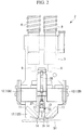
Fig. 2 is a front view showing a peening device according to the embodiment of the present invention. - [
Fig. 3 ]
Fig. 3 is a vertical cross-sectional view showing the peening device according to the embodiment of the present invention. - [
Fig. 4 ]
Fig. 4 is a perspective view showing the peening device according to the embodiment of the present invention. - [
Fig. 5 ]
Fig. 5 is a schematic diagram showing the peening device according to the embodiment of the present invention. - [
Fig. 6 ]
Fig. 6 is a block diagram showing the aircraft part manufacturing system according to the embodiment of the present invention. - [
Fig. 7 ]
Fig. 7 is a flowchart showing a method of manufacturing an aircraft part using the aircraft part manufacturing system according to the embodiment of the present invention. - [
Fig. 8 ]
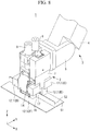
Fig. 8 is a perspective view showing a modification of the peening device according to the embodiment of the present invention. - [
Fig. 9A ]
Fig. 9 is a perspective view showing an integrated member. - [
Fig. 9B ]
Fig. 9B is a perspective view showing an aircraft part obtained by applying peen forming to the integrated member. - An aircraft
part manufacturing system 1 according to an embodiment of the present invention is capable of deforming a workpiece by a peen forming (peening machining) method. For example, the aircraftpart manufacturing system 1 is used to manufacture an aircraft part. An aircraft part here is a primary wing of an aircraft, for example. - In the following, a description will be given of a case where a skin, which is a plate-shaped member, and stringers, which are elongated members, are combined to manufacture a primary wing of an aircraft. In the following, an
integrated member 50, as shown inFig. 9A , integrating askin 51 andstringers 52, which is not yet machined by a peen forming method, and theskin 51 or thestringer 52 which is not yet machined will be referred to as "workpiece". - Furthermore, for the sake of convenience, a direction parallel to a longitudinal direction of the
stringer 52, as a workpiece, will be given as an X-axis, a direction parallel to a width direction of thestringer 52, which is perpendicular to the longitudinal direction, will be given as a Y-axis, and a direction parallel to a height direction of thestringer 52 will be given as a Z-axis. - A plurality of
stringers 52 are disposed on one surface of theskin 51, in parallel along one direction, and are integrally combined with theskin 51. Then, peen forming is applied to theskin 51 and the stringers 52 (workpiece) which are integrated, and theintegrated member 50 is plastically deformed, and an aircraft part such as a primary wing having a three-dimensional curved surface is manufactured. The peen forming method is a machining method of plastically deforming a workpiece by projecting steel balls (having a diameter of 5 mm, for example) called "shots" to the workpiece. As shown inFig. 9B , anaircraft part 55 after peen forming has a saddle shape, for example. That is, a cross section cut in parallel with an XZ plane has a curved line which protrudes downward, and a cross section cut in parallel with a YZ plane has a curved line which protrudes upward. - In the present embodiment, the
stringer 52, as a workpiece, is divided into a plurality of regions along the longitudinal direction, and target values of a curvature radius and a plate thickness are changed for each region. Machining may thereby be performed such thatintegrated skin 51 andstringer 52 are formed not only into a simple curved shape bent in one direction (i.e., a conical shape or a cylindrical shape), but also into a complex curved shape bent in two directions (i.e., a saddle shape). - As shown in
Fig. 1 , the aircraftpart manufacturing system 1 according to the present embodiment includes apeening device 2, amachining robot 3 having thepeening device 2 attached to ahand 5, and the like. - As shown in
Fig. 1 , themachining robot 3 includes anarm 4, and thehand 5 to which thepeening device 2 is fixed or which grasps thepeening device 2 is attached at a tip end of thearm 4. Themachining robot 3 adjusts a position or an orientation (posture) of thepeening device 2 by controlling a position or an orientation (posture) of thehand 5. Themachining robot 3 is controlled by acontrol unit 6. - As shown in
Figs. 1 to 3 , thepeening device 2 includes acasing 7, ashot supply section 8, anozzle 9, a blockingplate 10, areflection plate 11, asensor 12, aprotection section 13, and the like. - The above mentioned shot
supply section 8, thenozzle 9, the blockingplate 10, thereflection plate 11, thesensor 12, theprotection section 13, and the like are attached to thecasing 7. - The
shot supply section 8 is connected to an external supply tube (not shown), and a plurality of shots are continuously supplied through the supply tube. - The
nozzle 9 is installed at a tip end of theshot supply section 8, or in other words, on a downstream side of a flow of shots. Shots are projected from thenozzle 9 toward a workpiece. Positions and orientations of theshot supply section 8 and thenozzle 9 are fixed with respect to thecasing 7. As shown inFig. 5 , in the present embodiment, a shot which is projected from thenozzle 9 hits thereflection plate 11, and then hits thestringer 52, which is the workpiece. -
Nozzles 9 are installed along a Y-axis direction, one on each side of thestringer 52, which is the workpiece. Shots may be projected to plate surfaces of both sides of thestringer 52 by the twonozzles 9. - A shot passes through a
passage section 15, from thenozzle 9 to thereflection plate 11. The blockingplate 10 is an example of a blocking section, and is movably installed to thecasing 7 to be installed at thepassage section 15 or to be installed outside thepassage section 15. When the blockingplate 10 is moved and installed at thepassage section 15, a shot which is projected from thenozzle 9 is reflected in a direction different from a direction toward thestringer 52. As a result, while the blockingplate 10 is installed at thepassage section 15, a plurality of shots is not projected to thestringer 52, and deformation of thestringer 52 is prevented. On the other hand, when the blockingplate 10 is installed outside thepassage section 15, shots which are projected from thenozzle 9 are projected to thereflection plate 11, and the shots which are reflected by thereflection plate 11 are projected to thestringer 52. - The
reflection plate 11 is a plate-shaped member which is installed on a downstream side of thepassage section 15, and which reflects the shots. A material which is not easily deformed when hit by a shot is used for thereflection plate 11. For example, thereflection plate 11 is installed to change a flow direction of a shot, which is projected from thenozzle 9, toward thestringer 52. The flow direction of a shot toward the stringer is a direction which is approximately perpendicular to a plate surface of thestringer 52, or which forms an angle within a range of 60 degrees or more and 90 degrees or less with respect to the plate surface, for example. - An
opening section 16 where thestringer 52 can be inserted is formed at one end portion of thepeening device 2. Furthermore, a recessedsection 17 is formed at a side surface portion of thecasing 7 so as to allow insertion of thestringer 52 having an elongated shape. Asealant 14 that prevents shots from hitting theskin 51 is provided on theopening section 16, along an X-axis direction. Thesealant 14 is made of rubber, for example. - The
sensor 12 is installed on thecasing 7, and detects a distance to thestringer 52 or theskin 51, as a workpiece. Thesensor 12 is a laser displacement sensor, for example, and detects a distance to a measurement target by radiating laser light and receiving reflected laser light. Position and orientation of thesensor 12 are fixed with respect to thecasing 7, and relative positions and relative directions of thenozzle 9 and thesensor 12 are constant. Accordingly, the position and the orientation of thenozzle 9 may be changed based on a detection result of thesensor 12. Additionally, an installation direction of thesensor 12 may, but does not have to, be perpendicular to the measurement target. The distance from thesensor 12 to the measurement target is detected based on a measurement value which is converted according to an installation angle of thesensor 12. - As shown in
Fig. 4 ,sensors stringer 52, along the longitudinal direction of thestringer 52 which is installed at thepeening device 2, or in other words, along the X-axis direction. Thesensor skin 51 when the workpiece is installed at thepeening device 2. Thesensor sensor skin 51. - As shown in
Fig. 4 ,sensors stringer 52, along the longitudinal direction of thestringer 52 which is installed at thepeening device 2, or in other words, along the X-axis direction. Thesensor stringer 52 when the workpiece is installed at thepeening device 2. Thesensor sensor stringer 52. - As shown in
Fig. 4 , thesensors stringer 52 along the width direction, which is a direction perpendicular to the longitudinal direction of thestringer 52 installed at thepeening device 2, or in other words, along the Y-axis direction. Thesensor 12A is disposed on the one side of thestringer 52, and thesensor 12B is disposed on the other side of thestringer 52. Thesensor 12B is installed in a direction of radiating laser light toward a plate surface of theskin 51 when the workpiece is installed at thepeening device 2. Thesensor 12B detects a distance from thesensor 12B to theskin 51. - As shown in
Fig. 6 , thecontrol unit 6 of themachining robot 3 includesposition calculation units tilt calculation units position adjustment unit 23, atilt adjustment unit 24, aprojection control unit 25, amemory 26, and the like. Operation of thecontrol unit 6 is implemented by executing programs that are recorded in advance, and by hardware resources such as a CPU. - The
position calculation unit 18 calculates an average distance from thesensors skin 51, based on the distances detected by thesensor 12A and thesensor 12C, the distances detected by thesensor 12A and thesensor 12B, or the distances detected by thesensor 12A, thesensor 12B, and thesensor 12C. Additionally, installation positions of thesensors - The
position calculation unit 19 calculates an average distance from thesensors stringer 52, based on the distances detected by thesensor 12D and thesensor 12E. Additionally, installation positions of thesensors - The
tilt calculation unit 20 calculates a tilt angle of the longitudinal direction of thestringer 52 with respect to a horizontal plane, based on the distances detected by thesensor 12A and thesensor 12C. That is, a rotation angle around the Y-axis is calculated by thetilt calculation unit 20. - The
tilt calculation unit 21 calculates a tilt angle of the width direction of the stringer with respect to the horizontal plane, based on the distances detected by thesensor 12A and thesensor 12B. That is, a rotation angle around the X-axis is calculated by thetilt calculation unit 21. - The
tilt calculation unit 22 calculates a tilt angle of the longitudinal direction of the stringer with respect to the X-axis direction, based on the distances detected by thesensor 12D and thesensor 12E. That is, a rotation angle around the Z-axis is calculated by thetilt calculation unit 22. - The
position adjustment unit 23 adjusts a position of thepeening device 2, based on the average distances calculated by theposition calculation units - Specifically, the
position adjustment unit 23 adjusts a projection position in the Z-axis direction by using the average distance from thesensors skin 51 calculated by theposition calculation unit 18. Furthermore, theposition adjustment unit 23 adjusts the projection position in the Y-axis direction by using the average distance from thesensors stringer 52 calculated by theposition calculation unit 19. - At this time, the
position adjustment unit 23 calculates a corrected distance in such a way that the calculated average distance to theskin 51 or thestringer 52 falls within a range set by predetermined thresholds. Then, theposition adjustment unit 23 moves thearm 4 and thehand 5 of themachining robot 3 in the Z-axis direction or the Y-axis direction based on the calculated corrected distance, and thereby moves the position of thepeening device 2. The predetermined thresholds are recorded in advance in thememory 26, for example. - The
tilt adjustment unit 24 adjusts the orientation of thepeening device 2 based on the tilts calculated by thetilt calculation units - Specifically, the
tilt adjustment unit 24 adjusts the orientation (posture) of thepeening device 2 around the Y-axis by using the rotation angle around the Y-axis calculated by thetilt calculation unit 20. Furthermore, thetilt adjustment unit 24 adjusts the orientation (posture) of thepeening device 2 around the X-axis by using the rotation angle around the X-axis calculated by thetilt calculation unit 21. Furthermore, thetilt adjustment unit 24 adjusts the orientation (posture) of thepeening device 2 around the Z-axis by using the rotation angle around the Z-axis calculated by thetilt calculation unit 22. - At this time, the
tilt adjustment unit 24 calculates correction angles in such a way that the calculated rotation angles around the X-axis, the Y-axis, and the Z-axis fall within ranges set by predetermined thresholds. Then, thetilt adjustment unit 24 causes thehand 5 of themachining robot 3 to be rotated around the X-axis, the Y-axis, and the Z-axis based on the calculated correction angles, and thereby changes the orientation of thepeening device 2. The predetermined thresholds are recorded in advance in thememory 26, for example. - When the calculated distances and angles are determined to be within ranges set by predetermined thresholds, the
projection control unit 25 projects shots at thestringer 52. Shots may thus be projected with the position and the orientation of thepeening device 2 being in an optimal state for peening. - When the position and the orientation of the
peening device 2 are determined to be within the predetermined ranges, theprojection control unit 25 moves the blockingplate 10 to outside thepassage section 15 so that shots are projected to thestringer 52. On the other hand, when the position and the orientation of thepeening device 2 are determined to be outside the predetermined ranges, theprojection control unit 25 moves the blockingplate 10 to thepassage section 15 so that shots are not projected to thestringer 52. - After projection is started, the
projection control unit 25 determines whether or not a plate thickness or a curvature of thestringer 52 reached a target value, based on a detection result of the plate thickness or the curvature of thestringer 52, and when the plate thickness or the curvature is determined to have reached the target value, projection of shots is stopped. In this case, a detection unit (not shown) that detects the plate thickness or the curvature of thestringer 52 is provided. Alternatively, after projection is started, theprojection control unit 25 determines whether or not projection of a predetermined flow rate is completed, and when projection of a predetermined flow rate is determined to have been performed, projection of shots is stopped. To stop projection of shots, theprojection control unit 25 moves the blockingplate 10 to thepassage section 15. - As shown in
Figs. 2 and3 , theprotection section 13 includes acover portion 27 that covers an upper end portion of thestringer 52, and anelastic portion 28 which is applied with a force in a direction of pressing thecover portion 27 against thestringer 52. For example, thecover portion 27 is a member made of synthetic resin or rubber, and is a member that is long in one direction along the longitudinal direction of thestringer 52, or in other words, along the X-axis direction. A part of the workpiece is thereby covered by thecover portion 27 of theprotection section 13, when a plurality of shots is projected from thenozzle 9 to the workpiece and the workpiece is deformed, and thus, deformation of the part of the workpiece covered by thecover portion 27 may be prevented. A shape of thecover portion 27 on a side that comes into contact with thestringer 52 is tilted in an umbrella shape, and thus, corners of the workpiece may be reliably protected. - For example, the
elastic portion 28 is a compression spring or a cylinder mechanism. A force is applied to theelastic portion 28 in a direction of pressing thecover portion 27 against thestringer 52, when thestringer 52 is inserted into theopening section 16 and the upper end portion of thestringer 52 comes into contact with thecover portion 27. - Additionally, in the embodiment described above, a case where the
sensors stringer 52 along the X-axis direction is described, but asensor 12F may further be installed, as shown inFig. 8 . Thesensor 12F is disposed on the other side of thestringer 52 along the X-axis direction, together with thesensor 12B. Accordingly, the distance to theskin 51 may be more accurately detected in a case where the plate thickness of theskin 51 is different between the one side and the other side of thestringer 52. - Next, a method of manufacturing an aircraft part using the aircraft
part manufacturing system 1 according to the present embodiment will be described with reference toFig. 7 . - First, the
peening device 2 is installed in a region, of a workpiece before machining, where peen forming is to be performed (step S1). At this time, themachining robot 3 may detect a region where machining is to be performed, based on a positioning mark or the like, and may move thepeening device 2 based on the detection result. In this case, a detection unit (not shown) that detects a region where machining is to be performed is installed at themachining robot 3. - When the
stringer 52 is inserted into theopening section 16 of the peening device 2 (step S2), thecover portion 27 of theprotection section 13 comes into contact with thestringer 52, and theelastic portion 28 applies a force in a direction of pressing thecover portion 27 against thestringer 52. - Then, the
position calculation unit skin 51 or thestringer 52 based on the distances detected by thesensors 12. Furthermore, theposition adjustment unit 23 adjusts the position of thepeening device 2 by using the calculated average distance to theskin 51 or thestringer 52. Theposition adjustment unit 23 moves the position of thepeening device 2 by moving thehand 5 of themachining robot 3 along the Z-axis direction or the Y-axis direction based on a calculated correction distance (step S3). - Furthermore, the
tilt calculation units peening device 2 based on the distances detected by thesensors 12, and thetilt adjustment unit 24 adjusts the orientation of thepeening device 2. Thetilt adjustment unit 24 changes the orientation of thepeening device 2 by rotating thehand 5 of themachining robot 3 around the X-axis, the Y-axis, and the Z-axis based on calculated correction angles (step S4). - Furthermore, whether or not the distances and the angles calculated by the
position calculation units tilt calculation units peening device 2 in steps S3 and S4 are continued. - When the calculated distances and angles are determined to be within the ranges set by predetermined thresholds, shots are projected to the stringer 52 (step S6). Whether or not the distances and the angles calculated by the
position calculation units tilt calculation units peening device 2 are adjusted in steps S3 and S4. That is, because thestringer 52 and theskin 51, as a workpiece, are continuously deformed during projection of shots, the position and the orientation of thepeening device 2 continue to be adjusted so that the position and the orientation of thepeening device 2 are constantly within predetermined ranges. - After projection is started, whether or not the plate thickness or the curvature of the
stringer 52 reached a target value is determined based on a detection result of the plate thickness or the curvature of the stringer 52 (step S8), and when the plate thickness or the curvature is determined to have reached the target value, projection of shots is stopped (step S9). Alternatively, after projection is started, whether or not projection of a predetermined flow rate completed is determined (step S8), and when projection of the predetermined flow rate is determined to be completed, projection of shots is stopped (step S9). At this time, the blockingplate 10 is moved to thepassage section 15 to stop projection of shots to thestringer 52. - Then, whether or not peen forming is performed on all the regions where peen forming is to be performed is determined (step S10). In the case where peen forming is not performed on all the regions, the
peening device 2 is moved to another region where peen forming is to be performed (step S11). After thepeening device 2 is moved, peen forming is performed while detecting the position and the orientation of thepeening device 2 by the method described above (step S1 and subsequent steps). On the other hand, in the case where peen forming is determined to be complete for all the regions, the series of operations is ended. - As described above, according to the present embodiment, during projection of shots by the
peening device 2, the position and the orientation of thepeening device 2 are detected, and the position and the orientation of thepeening device 2 are adjusted. The position and the orientation of thepeening device 2 are adjusted to predetermined position and orientation which are set in advance, even while thestringer 52 and theskin 51, as a workpiece, are being continuously deformed. Accordingly, shots may be constantly and accurately blasted to predetermined positions, which are set in advance, of the workpiece. As a result, accurate machining may be performed on the workpiece formed of thestringer 52 and theskin 51. - Moreover, because the upper end portion of the
stringer 52 is protected from the shots by theprotection section 13, deformation of the corner of thestringer 52 due to being hit by a shot may be prevented, and occurrence of cracks and reduction in strength may be prevented. Conventionally, a rubber sheet or the like is used to prevent shots from directly hitting a region which should not be deformed, such as the corner of thestringer 52, but according to the present embodiment, the time and labor required to attach a rubber sheet may be eliminated, and use of sub-materials such as the rubber sheet may be reduced. Furthermore, thecover portion 27 is applied with a pressing force toward thestringer 52 while being protected by theprotection section 13 attached to thecasing 7, and thus, theprotection section 13 does not come off while shots are being projected at a high speed. Accordingly, an end portion of thestringer 52 is reliably protected, compared with a case of attaching a rubber sheet. - Moreover, because switching between projection and non-projection of shots may be performed by the blocking
plate 10, projection of shots may be stopped while moving between two regions where peen forming is to be performed (transient period). Accordingly, shots may be projected to thestringer 52 only when the position and the orientation of thepeening device 2 are securely determined, and shots are not projected when projection conditions of shots are not stable, and thus, unexpected deformation is not easily caused. Accordingly, accurate machining may be performed on a workpiece formed of thestringer 52 and theskin 51. -
- 1
- aircraft part manufacturing system
- 2
- peening devices
- 3
- machining robots
- 4
- arms
- 5
- hand
- 6
- control unit
- 7
- casing
- 8
- shot supply section
- 9
- nozzles
- 10
- blocking plate
- 11
- reflection plate
- 12
- sensors
- 12A
- sensor
- 12B
- sensor
- 12C
- sensor
- 12D
- sensor
- 12E
- sensor
- 12F
- sensor
- 13
- protection section
- 14
- sealants
- 15
- passage section
- 16
- opening section
- 17
- recessed section
- 18
- position calculation unit
- 19
- position calculation unit
- 20
- tilt calculation unit
- 21
- tilt calculation unit
- 22
- tilt calculation unit
- 23
- position adjustment unit
- 24
- tilt adjustment unit
- 25
- projection control unit
- 26
- memory
- 27
- cover portions
- 28
- elastic portions
- 50
- integrated members
- 51
- skin
- 52
- stringers
- 55
- aircraft part
Claims (6)
- A part manufacturing system comprising:a peening device includinga nozzle section that projects a plurality of shots toward a workpiece, anda detection unit that detects a distance to the workpiece; anda robot device includinga hand section to which the peening device is attached, anda control unit that adjusts a position or an orientation of the peening device by controlling the hand section based on the distance detected by the detection unit.
- The part manufacturing system according to claim 1, wherein
the workpiece is an elongated member,
at least two detection units are provided as the detection unit, and
the control unit adjusts the position of the peening device based on an average distance to the workpiece that is calculated from the distances detected by the at least two detection units. - The part manufacturing system according to claim 1 or 2, wherein
the workpiece is an elongated member,
at least two detection units are provided as the detection unit, and
the control unit adjusts the orientation of the peening device based on a tilt angle of the workpiece that is calculated from the distances detected by the at least two detection units. - The part manufacturing system according to any one of claims 1 to 3, wherein the peening device further includes a protection section that covers a part of the workpiece.
- The part manufacturing system according to any one of claims 1 to 4, wherein
the peening device further includes a blocking section that can be installed at a passage section where the shots pass through from the nozzle section to the workpiece, and that can be installed outside the passage section, and
when installed at the passage section, the blocking section reflects the shots projected from the nozzle section, in a direction different from a direction of the workpiece. - A part manufacturing method comprising the steps of:projecting, by a nozzle section, a plurality of shots toward a workpiece;detecting, by a detection unit, a distance to the workpiece; andadjusting, by a robot device to which a peening device including the nozzle section and the detection unit is attached, a position or an orientation of the peening device based on the distance detected by the detection unit.
Applications Claiming Priority (2)
| Application Number | Priority Date | Filing Date | Title |
|---|---|---|---|
| JP2017026204A JP6949503B2 (en) | 2017-02-15 | 2017-02-15 | Parts manufacturing system and parts manufacturing method |
| PCT/JP2018/005123 WO2018151168A1 (en) | 2017-02-15 | 2018-02-14 | Part manufacturing system and part manufacturing method |
Publications (2)
| Publication Number | Publication Date |
|---|---|
| EP3584036A1 true EP3584036A1 (en) | 2019-12-25 |
| EP3584036A4 EP3584036A4 (en) | 2020-12-02 |
Family
ID=63170385
Family Applications (1)
| Application Number | Title | Priority Date | Filing Date |
|---|---|---|---|
| EP18754120.6A Withdrawn EP3584036A4 (en) | 2017-02-15 | 2018-02-14 | PARTS MANUFACTURING SYSTEM AND PARTS MANUFACTURING PROCESS |
Country Status (6)
| Country | Link |
|---|---|
| US (1) | US11446786B2 (en) |
| EP (1) | EP3584036A4 (en) |
| JP (1) | JP6949503B2 (en) |
| CN (1) | CN110290896A (en) |
| CA (1) | CA3052133C (en) |
| WO (1) | WO2018151168A1 (en) |
Families Citing this family (7)
| Publication number | Priority date | Publication date | Assignee | Title |
|---|---|---|---|---|
| JP7259688B2 (en) * | 2019-10-02 | 2023-04-18 | 新東工業株式会社 | Shot processing apparatus and shot processing method |
| CN114786872A (en) * | 2019-12-12 | 2022-07-22 | 日本制铁株式会社 | Device for removing foreign matter on roll surface, method for removing foreign matter on roll surface, and method for manufacturing steel strip |
| CN111390732B (en) * | 2020-04-02 | 2021-09-24 | 中国民航大学 | Aircraft surface paint stripping and grinding device based on pressure control |
| CN115200982B (en) * | 2022-07-01 | 2025-07-15 | 中国航发贵州黎阳航空动力有限公司 | A shot peening strength testing method and shot peening fixture |
| CN115635004B (en) * | 2022-11-07 | 2024-02-23 | 中国航空制造技术研究院 | A shot peening method for saddle-shaped ribbed wall panels |
| US20240424640A1 (en) * | 2023-06-23 | 2024-12-26 | Electronics, Inc. | Distance and angle detection for shot peening nozzles |
| CN119304695B (en) * | 2024-11-02 | 2026-01-30 | 北京星航机电装备有限公司 | A manufacturing method for an automated grinding system for complex, irregularly shaped, thin-walled skins |
Family Cites Families (24)
| Publication number | Priority date | Publication date | Assignee | Title |
|---|---|---|---|---|
| US4432220A (en) * | 1981-09-10 | 1984-02-21 | United Technologies Corporation | Shot peening apparatus |
| US4694672A (en) * | 1984-01-05 | 1987-09-22 | Baughman Davis L | Method and apparatus for imparting a simple contour to a workpiece |
| JPH0683255U (en) * | 1993-03-25 | 1994-11-29 | 有限会社協同工業所 | Formwork cleaning device |
| JPH0890417A (en) * | 1994-09-20 | 1996-04-09 | Amada Co Ltd | Deburring method and device |
| JPH10560A (en) * | 1996-06-07 | 1998-01-06 | Sadayoshi Kawai | Blast processing equipment |
| JP2000225528A (en) * | 1999-02-05 | 2000-08-15 | Ishikawajima Harima Heavy Ind Co Ltd | High pressure water jetting device |
| CA2327846A1 (en) * | 1999-12-08 | 2001-06-08 | Nmf Canada Inc. | Improved automated method and apparatus for aircraft surface finishing |
| US6189356B1 (en) * | 2000-02-17 | 2001-02-20 | General Electric Company | Method and apparatus for peening |
| JP3740103B2 (en) | 2001-11-26 | 2006-02-01 | 三菱重工業株式会社 | Pean forming method and peen forming apparatus |
| US7032279B2 (en) * | 2002-10-18 | 2006-04-25 | General Electric Company | Apparatus and methods for repairing compressor airfoils in situ |
| JP2007136628A (en) * | 2005-11-21 | 2007-06-07 | Egawa Seisakusho Kk | Attachment for sand blast device |
| JP2008049369A (en) | 2006-08-24 | 2008-03-06 | Aikoku Alpha Corp | Method of forming metal sheet |
| JP5001762B2 (en) * | 2007-09-13 | 2012-08-15 | 三菱重工業株式会社 | Attitude control method and attitude control device |
| JP5401217B2 (en) * | 2009-09-03 | 2014-01-29 | エーエスアーベー カッティング システムズ ゲゼルシャフト ミット ベシュレンクテル ハフツング | A tool station that can be moved over the portal for processing, including a granular material injection unit and a marking tool |
| US7966856B1 (en) | 2009-12-15 | 2011-06-28 | General Electric Company | Robotic peening apparatus |
| TWI499483B (en) * | 2010-11-01 | 2015-09-11 | Sintokogio Ltd | Nozzle handling device |
| US9003936B2 (en) | 2011-07-29 | 2015-04-14 | Flow International Corporation | Waterjet cutting system with standoff distance control |
| CN202491181U (en) * | 2012-03-05 | 2012-10-17 | 山东开泰工业科技有限公司 | Strip steel through type shot blasting machine |
| JP6138450B2 (en) * | 2012-10-10 | 2017-05-31 | 三菱重工業株式会社 | Peening apparatus and peening method |
| JP6104725B2 (en) | 2013-06-12 | 2017-03-29 | 三菱重工業株式会社 | Torsion holding device, torsion holding method and torsion forming method for plate-like workpiece |
| EP2848367B1 (en) | 2013-09-11 | 2016-03-23 | Rolls-Royce Deutschland Ltd & Co KG | Apparatus and method for shot peening of blade mounting areas on a rotor arrangement disc |
| JP5780371B1 (en) * | 2014-03-10 | 2015-09-16 | 新東工業株式会社 | Shot processing device |
| JP6420095B2 (en) * | 2014-08-28 | 2018-11-07 | ブラスト工業株式会社 | Blasting apparatus and blasting method |
| JP7259688B2 (en) * | 2019-10-02 | 2023-04-18 | 新東工業株式会社 | Shot processing apparatus and shot processing method |
-
2017
- 2017-02-15 JP JP2017026204A patent/JP6949503B2/en active Active
-
2018
- 2018-02-14 CN CN201880009177.4A patent/CN110290896A/en active Pending
- 2018-02-14 WO PCT/JP2018/005123 patent/WO2018151168A1/en not_active Ceased
- 2018-02-14 CA CA3052133A patent/CA3052133C/en active Active
- 2018-02-14 US US16/482,117 patent/US11446786B2/en active Active
- 2018-02-14 EP EP18754120.6A patent/EP3584036A4/en not_active Withdrawn
Also Published As
| Publication number | Publication date |
|---|---|
| CA3052133A1 (en) | 2018-08-23 |
| CA3052133C (en) | 2023-06-13 |
| US20190389035A1 (en) | 2019-12-26 |
| WO2018151168A1 (en) | 2018-08-23 |
| JP2018130799A (en) | 2018-08-23 |
| EP3584036A4 (en) | 2020-12-02 |
| JP6949503B2 (en) | 2021-10-13 |
| CN110290896A (en) | 2019-09-27 |
| US11446786B2 (en) | 2022-09-20 |
Similar Documents
| Publication | Publication Date | Title |
|---|---|---|
| US11446786B2 (en) | Part manufacturing system and part manufacturing method | |
| US9636827B2 (en) | Robot system for performing force control | |
| EP2042278B1 (en) | Robot controller for halting a robot based on the speed of a robot hand portion | |
| US9008820B2 (en) | Method of compensation for a fluid cutting apparatus | |
| US9915516B2 (en) | Method for controlling shape measuring apparatus | |
| US10131025B2 (en) | Workpiece positioning device for positioning workpiece | |
| US11161697B2 (en) | Work robot system and work robot | |
| US20160052043A1 (en) | Compensating device for a tool unit and fitting method by means of the tool unit | |
| EP0104270A1 (en) | Robot control apparatus | |
| US10759064B2 (en) | Robot and method for designing robot shape | |
| GB2547200B (en) | Tool center point setting method for articulated robot | |
| US9889488B2 (en) | Peening device and peening method | |
| US20160008980A1 (en) | Inspection system for inspecting object using force sensor | |
| CN111977016B (en) | Mark knife bending shot blasting shape correction method for wing skin without ribs | |
| CN116100167B (en) | A three-dimensional five-axis cutting head and its control method | |
| EP2159657A1 (en) | Method and control system for synchronisation of robot and conveyor | |
| JP2688372B2 (en) | Robot trajectory control device | |
| CN104787356A (en) | Rudder position adjusting and measuring clamp and method | |
| EP4427880B1 (en) | Robotic polishing system and method for using same | |
| CN215749277U (en) | A anticollision piece for robot TCP detects | |
| US11420345B2 (en) | Robot | |
| EP3502672B1 (en) | Methods and systems for visual inspection | |
| EP3465081B1 (en) | Bending angle measurement system | |
| CN122007944A (en) | Self-adaptive presser foot device for robot end effector and end effector | |
| CN118081635A (en) | A fork-type shot peening gun capable of measuring machining gap in real time |
Legal Events
| Date | Code | Title | Description |
|---|---|---|---|
| STAA | Information on the status of an ep patent application or granted ep patent |
Free format text: STATUS: THE INTERNATIONAL PUBLICATION HAS BEEN MADE |
|
| PUAI | Public reference made under article 153(3) epc to a published international application that has entered the european phase |
Free format text: ORIGINAL CODE: 0009012 |
|
| STAA | Information on the status of an ep patent application or granted ep patent |
Free format text: STATUS: REQUEST FOR EXAMINATION WAS MADE |
|
| 17P | Request for examination filed |
Effective date: 20190729 |
|
| AK | Designated contracting states |
Kind code of ref document: A1 Designated state(s): AL AT BE BG CH CY CZ DE DK EE ES FI FR GB GR HR HU IE IS IT LI LT LU LV MC MK MT NL NO PL PT RO RS SE SI SK SM TR |
|
| AX | Request for extension of the european patent |
Extension state: BA ME |
|
| DAV | Request for validation of the european patent (deleted) | ||
| DAX | Request for extension of the european patent (deleted) | ||
| A4 | Supplementary search report drawn up and despatched |
Effective date: 20201029 |
|
| RIC1 | Information provided on ipc code assigned before grant |
Ipc: B23P 9/00 20060101ALI20201023BHEP Ipc: B64C 3/00 20060101ALI20201023BHEP Ipc: B24C 1/10 20060101AFI20201023BHEP Ipc: B64C 1/12 20060101ALI20201023BHEP Ipc: B24B 27/00 20060101ALI20201023BHEP Ipc: B21D 31/06 20060101ALN20201023BHEP Ipc: C21D 7/06 20060101ALI20201023BHEP Ipc: B24C 3/32 20060101ALI20201023BHEP Ipc: B24C 1/04 20060101ALI20201023BHEP Ipc: B64C 3/26 20060101ALI20201023BHEP Ipc: C21D 7/00 20060101ALI20201023BHEP Ipc: B25J 13/08 20060101ALI20201023BHEP Ipc: B64F 5/10 20170101ALI20201023BHEP |
|
| STAA | Information on the status of an ep patent application or granted ep patent |
Free format text: STATUS: EXAMINATION IS IN PROGRESS |
|
| 17Q | First examination report despatched |
Effective date: 20230118 |
|
| REG | Reference to a national code |
Ref country code: DE Ref legal event code: R079 Free format text: PREVIOUS MAIN CLASS: B24C0001100000 Ipc: B24C0001040000 |
|
| RIC1 | Information provided on ipc code assigned before grant |
Ipc: B64C 3/18 20060101ALI20230824BHEP Ipc: B64F 5/10 20170101ALI20230824BHEP Ipc: B64C 3/26 20060101ALI20230824BHEP Ipc: B25J 13/08 20060101ALI20230824BHEP Ipc: B24C 3/32 20060101ALI20230824BHEP Ipc: B24C 1/10 20060101ALI20230824BHEP Ipc: B24B 27/00 20060101ALI20230824BHEP Ipc: B24C 1/04 20060101AFI20230824BHEP |
|
| GRAP | Despatch of communication of intention to grant a patent |
Free format text: ORIGINAL CODE: EPIDOSNIGR1 |
|
| STAA | Information on the status of an ep patent application or granted ep patent |
Free format text: STATUS: GRANT OF PATENT IS INTENDED |
|
| INTG | Intention to grant announced |
Effective date: 20231116 |
|
| RAP3 | Party data changed (applicant data changed or rights of an application transferred) |
Owner name: SINTOKOGIO, LTD. Owner name: MITSUBISHI HEAVY INDUSTRIES, LTD. |
|
| STAA | Information on the status of an ep patent application or granted ep patent |
Free format text: STATUS: THE APPLICATION IS DEEMED TO BE WITHDRAWN |
|
| 18D | Application deemed to be withdrawn |
Effective date: 20240319 |