EP3583639B1 - Electric vehicle battery cell with solid state electrolyte - Google Patents
Electric vehicle battery cell with solid state electrolyte Download PDFInfo
- Publication number
- EP3583639B1 EP3583639B1 EP18718189.6A EP18718189A EP3583639B1 EP 3583639 B1 EP3583639 B1 EP 3583639B1 EP 18718189 A EP18718189 A EP 18718189A EP 3583639 B1 EP3583639 B1 EP 3583639B1
- Authority
- EP
- European Patent Office
- Prior art keywords
- battery
- current collector
- recited
- bipolar current
- frame
- Prior art date
- Legal status (The legal status is an assumption and is not a legal conclusion. Google has not performed a legal analysis and makes no representation as to the accuracy of the status listed.)
- Active
Links
Images




Classifications
-
- H—ELECTRICITY
- H01—ELECTRIC ELEMENTS
- H01M—PROCESSES OR MEANS, e.g. BATTERIES, FOR THE DIRECT CONVERSION OF CHEMICAL ENERGY INTO ELECTRICAL ENERGY
- H01M4/00—Electrodes
- H01M4/02—Electrodes composed of, or comprising, active material
- H01M4/64—Carriers or collectors
- H01M4/66—Selection of materials
- H01M4/665—Composites
- H01M4/667—Composites in the form of layers, e.g. coatings
-
- H—ELECTRICITY
- H01—ELECTRIC ELEMENTS
- H01M—PROCESSES OR MEANS, e.g. BATTERIES, FOR THE DIRECT CONVERSION OF CHEMICAL ENERGY INTO ELECTRICAL ENERGY
- H01M4/00—Electrodes
- H01M4/02—Electrodes composed of, or comprising, active material
- H01M4/64—Carriers or collectors
- H01M4/66—Selection of materials
- H01M4/664—Ceramic materials
-
- B—PERFORMING OPERATIONS; TRANSPORTING
- B60—VEHICLES IN GENERAL
- B60L—PROPULSION OF ELECTRICALLY-PROPELLED VEHICLES; SUPPLYING ELECTRIC POWER FOR AUXILIARY EQUIPMENT OF ELECTRICALLY-PROPELLED VEHICLES; ELECTRODYNAMIC BRAKE SYSTEMS FOR VEHICLES IN GENERAL; MAGNETIC SUSPENSION OR LEVITATION FOR VEHICLES; MONITORING OPERATING VARIABLES OF ELECTRICALLY-PROPELLED VEHICLES; ELECTRIC SAFETY DEVICES FOR ELECTRICALLY-PROPELLED VEHICLES
- B60L50/00—Electric propulsion with power supplied within the vehicle
- B60L50/50—Electric propulsion with power supplied within the vehicle using propulsion power supplied by batteries or fuel cells
- B60L50/60—Electric propulsion with power supplied within the vehicle using propulsion power supplied by batteries or fuel cells using power supplied by batteries
- B60L50/64—Constructional details of batteries specially adapted for electric vehicles
-
- H—ELECTRICITY
- H01—ELECTRIC ELEMENTS
- H01M—PROCESSES OR MEANS, e.g. BATTERIES, FOR THE DIRECT CONVERSION OF CHEMICAL ENERGY INTO ELECTRICAL ENERGY
- H01M10/00—Secondary cells; Manufacture thereof
- H01M10/04—Construction or manufacture in general
- H01M10/0413—Large-sized flat cells or batteries for motive or stationary systems with plate-like electrodes
- H01M10/0418—Large-sized flat cells or batteries for motive or stationary systems with plate-like electrodes with bipolar electrodes
-
- H—ELECTRICITY
- H01—ELECTRIC ELEMENTS
- H01M—PROCESSES OR MEANS, e.g. BATTERIES, FOR THE DIRECT CONVERSION OF CHEMICAL ENERGY INTO ELECTRICAL ENERGY
- H01M4/00—Electrodes
- H01M4/02—Electrodes composed of, or comprising, active material
- H01M4/64—Carriers or collectors
- H01M4/66—Selection of materials
- H01M4/661—Metal or alloys, e.g. alloy coatings
-
- H—ELECTRICITY
- H01—ELECTRIC ELEMENTS
- H01M—PROCESSES OR MEANS, e.g. BATTERIES, FOR THE DIRECT CONVERSION OF CHEMICAL ENERGY INTO ELECTRICAL ENERGY
- H01M4/00—Electrodes
- H01M4/02—Electrodes composed of, or comprising, active material
- H01M4/64—Carriers or collectors
- H01M4/66—Selection of materials
- H01M4/661—Metal or alloys, e.g. alloy coatings
- H01M4/662—Alloys
-
- H—ELECTRICITY
- H01—ELECTRIC ELEMENTS
- H01M—PROCESSES OR MEANS, e.g. BATTERIES, FOR THE DIRECT CONVERSION OF CHEMICAL ENERGY INTO ELECTRICAL ENERGY
- H01M50/00—Constructional details or processes of manufacture of the non-active parts of electrochemical cells other than fuel cells, e.g. hybrid cells
- H01M50/10—Primary casings; Jackets or wrappings
- H01M50/102—Primary casings; Jackets or wrappings characterised by their shape or physical structure
- H01M50/103—Primary casings; Jackets or wrappings characterised by their shape or physical structure prismatic or rectangular
-
- H—ELECTRICITY
- H01—ELECTRIC ELEMENTS
- H01M—PROCESSES OR MEANS, e.g. BATTERIES, FOR THE DIRECT CONVERSION OF CHEMICAL ENERGY INTO ELECTRICAL ENERGY
- H01M50/00—Constructional details or processes of manufacture of the non-active parts of electrochemical cells other than fuel cells, e.g. hybrid cells
- H01M50/10—Primary casings; Jackets or wrappings
- H01M50/116—Primary casings; Jackets or wrappings characterised by the material
- H01M50/121—Organic material
-
- H—ELECTRICITY
- H01—ELECTRIC ELEMENTS
- H01M—PROCESSES OR MEANS, e.g. BATTERIES, FOR THE DIRECT CONVERSION OF CHEMICAL ENERGY INTO ELECTRICAL ENERGY
- H01M50/00—Constructional details or processes of manufacture of the non-active parts of electrochemical cells other than fuel cells, e.g. hybrid cells
- H01M50/40—Separators; Membranes; Diaphragms; Spacing elements inside cells
- H01M50/409—Separators, membranes or diaphragms characterised by the material
- H01M50/431—Inorganic material
- H01M50/434—Ceramics
-
- H—ELECTRICITY
- H01—ELECTRIC ELEMENTS
- H01M—PROCESSES OR MEANS, e.g. BATTERIES, FOR THE DIRECT CONVERSION OF CHEMICAL ENERGY INTO ELECTRICAL ENERGY
- H01M50/00—Constructional details or processes of manufacture of the non-active parts of electrochemical cells other than fuel cells, e.g. hybrid cells
- H01M50/40—Separators; Membranes; Diaphragms; Spacing elements inside cells
- H01M50/409—Separators, membranes or diaphragms characterised by the material
- H01M50/431—Inorganic material
- H01M50/434—Ceramics
- H01M50/437—Glass
-
- H—ELECTRICITY
- H01—ELECTRIC ELEMENTS
- H01M—PROCESSES OR MEANS, e.g. BATTERIES, FOR THE DIRECT CONVERSION OF CHEMICAL ENERGY INTO ELECTRICAL ENERGY
- H01M4/00—Electrodes
- H01M4/02—Electrodes composed of, or comprising, active material
- H01M2004/026—Electrodes composed of, or comprising, active material characterised by the polarity
- H01M2004/029—Bipolar electrodes
-
- H—ELECTRICITY
- H01—ELECTRIC ELEMENTS
- H01M—PROCESSES OR MEANS, e.g. BATTERIES, FOR THE DIRECT CONVERSION OF CHEMICAL ENERGY INTO ELECTRICAL ENERGY
- H01M2220/00—Batteries for particular applications
- H01M2220/20—Batteries in motive systems, e.g. vehicle, ship, plane
-
- Y—GENERAL TAGGING OF NEW TECHNOLOGICAL DEVELOPMENTS; GENERAL TAGGING OF CROSS-SECTIONAL TECHNOLOGIES SPANNING OVER SEVERAL SECTIONS OF THE IPC; TECHNICAL SUBJECTS COVERED BY FORMER USPC CROSS-REFERENCE ART COLLECTIONS [XRACs] AND DIGESTS
- Y02—TECHNOLOGIES OR APPLICATIONS FOR MITIGATION OR ADAPTATION AGAINST CLIMATE CHANGE
- Y02E—REDUCTION OF GREENHOUSE GAS [GHG] EMISSIONS, RELATED TO ENERGY GENERATION, TRANSMISSION OR DISTRIBUTION
- Y02E60/00—Enabling technologies; Technologies with a potential or indirect contribution to GHG emissions mitigation
- Y02E60/10—Energy storage using batteries
-
- Y—GENERAL TAGGING OF NEW TECHNOLOGICAL DEVELOPMENTS; GENERAL TAGGING OF CROSS-SECTIONAL TECHNOLOGIES SPANNING OVER SEVERAL SECTIONS OF THE IPC; TECHNICAL SUBJECTS COVERED BY FORMER USPC CROSS-REFERENCE ART COLLECTIONS [XRACs] AND DIGESTS
- Y02—TECHNOLOGIES OR APPLICATIONS FOR MITIGATION OR ADAPTATION AGAINST CLIMATE CHANGE
- Y02P—CLIMATE CHANGE MITIGATION TECHNOLOGIES IN THE PRODUCTION OR PROCESSING OF GOODS
- Y02P70/00—Climate change mitigation technologies in the production process for final industrial or consumer products
- Y02P70/50—Manufacturing or production processes characterised by the final manufactured product
Definitions
- the present invention relates generally to electric vehicles and more particularly to batteries for electric vehicles.
- U.S. Patent Application Publication No. 2013/0157111 discloses a casing for a lithium bipolar electrochemical battery including a bipolar element.
- the casing includes a composite material including a matrix and at least one porous reinforcement, the matrix of which includes at least one hardened polymer impregnating the at least one porous reinforcement, wherein the at least one porous reinforcement and the at least one hardened polymer encase the bipolar element and maintain a determined pressure on either side of the bipolar element to maintain a determined contact between its constituents.
- the bipolar element includes lower and upper electrodes separated from a bipolar electrode by two separators, in which an electrolyte is present in a liquid or gel form. Sealing against the electrolytes of the battery between two constituted adjacent electrochemical cells is provided by a seal which is produced by deposition of resin or adhesive on the periphery of all the electrodes.
- U.S. Patent Application No. 2013/0101878 discloses a battery comprising a plurality of self-contained, substantially cuboid cell housings, in each of which a side face is formed at least in some regions as a negative pole and the opposite side face is designed at least in some regions as a positive pole.
- the cell housings bear against one another, with the pole on the pole, and extend between a positive contact and a negative contact, and wherein the cell housings are each enclosed by an electrically non-conductive, mechanically supporting frame.
- the cell housing is filled with electrolyte on both sides of a bimetal.
- U.S. Patent Application No. 2004/0253512 discloses a bipolar battery including a bipolar electrode and an electrolyte layer.
- the bipolar electrode includes a current collector, a positive electrode layer formed on one surface of the current collector, and a negative electrode layer formed on the other surface of the current collector.
- the bipolar electrode is sequentially laminated to provide connection in series via the electrolyte layer to form a stack structure.
- the positive electrode layer, the negative electrode layer and the electrolyte layer are potted with a resin portion.
- a polymer gel electrolyte can include a solid polymer electrolyte with an ion conductivity.
- U.S. Patent Application No. 2003/0013012 discloses an electrochemical element comprising electrochemical cells which are multiply stacked.
- the electrochemical cells are formed by stacking: i) a bicell having a cathode; a separator layer; an anode; another separator layer; and another cathode sequentially as a basic unit; or ii) a bicell having an anode; a separator layer; a cathode; another separator layer; and another anode sequentially as a basic unit.
- a separator film is interposed between each of the stacked bicells.
- U.S. Patent Application No. 2016/0141623 discloses a bipolar electrode having a solid electrolyte, an anode slurry and a cathode slurry, each of which may be provided on a first surface and a second surface of the solid electrolyte, respectively, spacers provided in the anode slurry and the cathode slurry, and a metal substrate provided on the anode slurry and the cathode slurry.
- the electrode can be dried and pressed, and stacked to form an all-solid state battery.
- U.S. Patent Application No. 2011/014520 discloses a thin bipolar solid-state battery that includes a positive electrode, a negative electrode, a bipolar electrode, electrolyte-containing separators, and a sealing member.
- the sealing member is in form of a frame that includes a rectangular hole formed at the center of the sealing member and is disposed between the positive electrode and the bipolar electrode, the positive electrode active material layer, the negative electrode active material layer, and the electrolyte-containing separator are inserted into this hole. http://www.toyota-global.com/innovation/environmental_technology/keytech/ describes some of the advantages of all solid-state batteries.
- the present invention advantageously creates a battery unit that is easily stackable, while using a solid-state electrolyte that can create battery cells that are connected internally in series to produce high-voltage battery cells.
- the battery using a bipolar current collector foil can have a reduced weight and enhanced safety.
- the cathode preferably is deposited on the bipolar current collector and the anode preferably is deposited as a film on a second side of the bipolar current collector foil opposite the first side.
- the bipolar current collector advantageously can be made of aluminum and coated with nickel, copper or their alloys or carbon.
- the foil also could be a graphite foil.
- the use of aluminum foil, especially coated with nickel, has a great advantage in the present invention, as the thickness of the current collector can be smaller than 15 micrometers, and even 10 micrometers or less. This can lead to large weight and cost reductions.
- the foil is fixedly attached to a polymer frame.
- the polymer frame can for example be a rigid structure or a dense foil, perforated foil, porous foil, adhesive tape or adhesive foil, and maybe for example be made of polyethylene, polypropylene or a mixture of the two, and has a window to permit for example a cathode or anode material to extend therethrough.
- the bipolar current collector foil can be attached to the frame for example by gluing, welding heat bonding, lamination or adhesive tape.
- a nickel-coated side of an aluminum bipolar current collector foil can be attached directly to the frame.
- the material deposited for the cathode can include such as lithium metal or carbon.
- the anode material can also be deposited on the bipolar current collector and can be made of similar materials.
- the present invention also provides a battery module comprising: a plurality of the battery units described above connected in series, as well as an electric vehicle battery comprising a plurality of the battery modules connected in series or in parallel.
- An electric vehicle comprising the battery is also provided.
- Fig. 1 shows a battery cell module 10 with five stackable battery components 11, 12, 13, 14, 15 having electrode components according to an embodiment of the present invention.
- Each battery component 11, 12, 13, 14, 15 includes an anode 24, a separator 28, a cathode 26 and a bipolar current collector 22.
- Each component also includes a polymer frame 20, which on a planar side 124 has the bipolar current collector 22 and on an opposite planar side 128 has the separator 28.
- Polymer frame 20 in this embodiment is a polymer foil, and the attachment of separator 28 to frame 20 will be described in more detail with respect to Figs. 3a, 3b and 3c .
- Polymer frame 20 can be made for example of polypropylene (PP), polyethylene (PE), acrylnitrile butadiene-styrene (ABS), polyamide (PA), polylactic acid (PLA), poly (methyl methacrylate) (PMMA), polycarbonate (PC), polyethylene terephthalate (PET), polystyrene (PS), polyvinyl chloride (PVC), polyphenylene sulfide (PPS), polyphenylene oxide (PPO), Polyetherimide (PEI), polyether ether ketone (PEEK), polyether sulfone (PES), polybenzimidazole (PBI), nylon und composite foil or multilayer foil made of aluminum foil coated with a polymer for example polypropylene. Most preferably, the polymer frame is a PE/PP mixture.
- the present invention uses solid-state electrolytes like lithium oxide or sulfide glasses or glass ceramics or ceramics as separator 28. Liquid or gel electrolytes thus advantageously can be dispensed with, and the polymer frame can provide support for the more fragile separator material.
- Bipolar current collector 22 can be made of copper or aluminum or nickel-coated aluminum or nickel for example.
- Anode 24 and cathode 26 can be deposited for example by vapor deposition or other film technology on bipolar current collector 22.
- Fig. 2 shows a side view of the embodiment of Fig. 1 with a housing 40 connected to the polymer frames 20 of the battery components 11 to 15 to form a battery module cell.
- the housing can have for example four walls to cover each side of polymer frames 20, which preferably have a rectangular outer shape.
- Housing 40 may be made of the same material as polymer frames 20 for example, or of a different polymer material.
- a rod 99 as shown in Fig. 1 can interact with feed holes in the polymer frames 20 as will be described, and can be removed after the stack is created and the housing is added.
- Figs. 3a, 3b and 3c show a top view of creation of the embodiment of the battery component of the present invention
- Fig. 3d shows an alternate battery component with the bipolar current collector 22 first connected to the polymer frame.
- Fig. 3a shows a side 128 of a polymer frame 20 with a rectangular window 60.
- frame 20 can be placed over separator 28, which can have an anode 24 on one side and cathode 26 on the other side as shown in Fig. 1 .
- Cathode 26 protrudes through window 60, as shown in Fig. 3c .
- Frame 20 likewise is attached to separator 28 around window 60.
- Bipolar current collector 22, anode 24 and cathode 26 can be connected to this stackable component as discussed above or also can added separately or later during assembly.
- the anode and the cathode advantageously can be made of polymer, glass, glassceramic or ceramic solid-state materials, and the mechanical properties are improved and much of the mechanical stress during the cell assembly process can be retained by the polymer frame, which lowers the requirements on the assembly process. In addition, small imperfections at the solid-state material edges can be tolerated and the amount of defective goods can be decreased.
- Fig. 3d shows an alternate embodiment which starts out with the same frame 20 as in Fig. 3a .
- Bipolar current collector 22 which can be a thin foil of aluminum coated with nickel, is placed nickel side down on the frame to overlap side 128. Gluing or other bonding can be used to attach the nickel coating to a PP/PE frame, which advantageously provides a stable connection compares to a PP/PE aluminum or copper connection.
- the thin foil of the current collector 22 is also stabilized well, and then the cathode 26, separator 28 and anode 24 can be added separately to the combined frame 20/current collector 22 component.
- Figs. 4a, 4b, 4c, 4d, 4e and 4f show various frame geometries of the polymer frames according to the present invention, with Fig. 4a being similar to Fig. 3a , and frames 201, 202, 203, 204, 205 having a window 301 with rounded edges, a circular window 302, a window 303 similar to window 301 but smaller for a same outer sized frame, a perfectly square window 304 and an oval window 305, respectively.
- Fig. 4g shows a polymer frame 206 with for example four windows 306, 307, 308, 309.
- Fig. 5 shows a polymer frame 203 according to the present invention with feed holes 305 for easing assembly.
- Assembly of the Fig.1 embodiment can occur as follows: endplate anode current collector 92 is provided, and then battery component 11 is added so that frame 20 is slid over rod 99 via a feed hole 305. Polymer frame 20 can be slid over further rods via feed holes 305. Components 12, 13, 14 and 15 then can be stacked over the rod 99 as shown in Fig. 1 , and finally cathode top plate 90 added to create the battery module 10. The anode 24 of a battery component 12, 13, 14, 15 thus can rest on the bipolar current collector 22 of the battery component 11, 12, 13, 14, respectively, below.
- the rod 99 can be removed and housing 40 sides can be added and attached to the polymer frames.
- Fig. 6 shows a battery with two modules, the top module 120 being similar to module 10 but having a plate or tab at the anode side extending in a different lateral direction, this plate being a so-called middle plate 94.
- the bottom frame of top module 120 can be omitted.
- the bottom module 130 can simply be the inverse, with an anode extending through a window contacting the middle plate 94 and the frames bonded together with the middle plate or tab 94 extending, preferably on a side opposite the cathode end plates.
- the end plates can be anode end plates and the cathode can extend in the middle.
- a battery module with simply one endplate at an end of the housing can be created, identified herein as a module EP, the endplate preferably extending laterally past the housing.
- a so-called module EMP with one endplate and one middle plate connector extending laterally from another side of the housing as the endplate, can be created.
- a module MP with solely one middle plate and no other endplate, and a module TMP with two middle plates can also be created.
- Fig. 6 thus shows a EMP/EP combination.
- Fig. 7 for example shows two modules EP in series with the frame bonded at a weld 210, and an extra end plate 190 to create a higher voltage battery.
- Fig. 8 shows schematically a further battery configuration with two EP modules and a TMP module in the middle.
- Other configurations such as EP/MP/EMP or EP/MP/TMP/EP are also possible.
- the battery cell module or stack 110 can be created for example with a much larger number of battery cells for providing power as an electric battery to an electric motor 200 for powering an electric vehicle 300.
- the bipolar current collector foil with the solid state separator material By using the bipolar current collector foil with the solid state separator material as above, several advantages result.
- the external wiring of the cells is sophisticated and expensive.
- the battery pack of s prior art eGolf consists of 22 modules with each 12 cells.
- the weight of the electrical wires and cell connectors contributes significantly to the cell weight and the costs of the battery pack. The weight and the costs depends strongly on the amount of current.
- Increasing voltage via an internal series connection as in the present invention, without wiring helps to reduce the amount of copper wires/connectors.
- the internal series connection of electrodes without wiring as in the present invention allows to build cells with very different voltages. Cells with nominal voltages around 12 volts, 24 volts, 48 volts up to 800 volts are preferred. These cells then can be connected in parallel or in series as desired, as described above.
- bipolar current collector material Even pure aluminum foil can used as bipolar current collector material.
- the bipolar current collector is thinner than in a conventional lithium-ion battery and parallel connection of electrodes internally leads to cost and weight reduction due to use of Al current collectors and less tabs in the cell.
- solid-state lithium cells also allow for the usage of aluminum foil as anode current collector foil, which may not be possible for conventional lithium ion cells due to lithium intercalation reaction into the aluminum, which causes cracking and corrosion of the aluminum.
- the battery can be made of a couple up to hundreds of small battery cells.
- a module cell is made of 140 cells of 10 ⁇ 15 cm electrode size, with 3.7 V per cell gives 518 V as the module cell voltage with a capacity of 0.45 Ah, and has similar energy to a classic 63 Ah, 3.7 V cell.
- the module cells are the parallel-connected cells, for example one module cell in serial and 12 in parallel. The same failure (short circuit of anode and cathode) in this battery would lead to a capacity loss of just 0.71% and in the case of a failure of a whole module, a capacity loss of 8.3%.
- Another advantage is that all module cells are parallel connected so that even if several malfunction, there is a loss in the battery capacity but never a shutdown of the whole battery-system.
- the present invention also enhances the manufacturing speed of high-voltage and ultra-high-voltage modules with additionally supporting the high-voltage and ultra-high-voltage module cells to get more shock/vibration resistance for the use in a horizontal or vertical battery position.
- the frame-supported separators do not just increase the speed of stacking the single battery cells to a module cell, further those frames can be used for fixing the stack (module cell) for transport and build/assemble modules faster.
- After stacking all single battery cells can, with the help of the frames, be glued, welded or laminated together without moving the stack. This stabilizes the stack/module cell; all cells remain their positions; immediately without moving the stack into an extra cell housing.
- This double-coated electrode or middle plate has the function of an "end plate” for two module cells and this middle plate connect both module cells with each other. This reduces the assembling time by stacking the module cells to a module also the internal wiring. The production time for a module will be decrease.
- a further advantage of the sealed module cell is the flexible polymer-frame, which stabilizes the each single battery cell and reduces the vibration force by absorbing energy through swinging.
- each fragile separator has its own suspension to lower the vibration/shock force.
Landscapes
- Chemical & Material Sciences (AREA)
- Engineering & Computer Science (AREA)
- Chemical Kinetics & Catalysis (AREA)
- Electrochemistry (AREA)
- General Chemical & Material Sciences (AREA)
- Materials Engineering (AREA)
- Ceramic Engineering (AREA)
- Inorganic Chemistry (AREA)
- Sustainable Energy (AREA)
- Manufacturing & Machinery (AREA)
- Life Sciences & Earth Sciences (AREA)
- Sustainable Development (AREA)
- Power Engineering (AREA)
- Transportation (AREA)
- Mechanical Engineering (AREA)
- Composite Materials (AREA)
- Secondary Cells (AREA)
- Battery Electrode And Active Subsutance (AREA)
Description
- The present invention relates generally to electric vehicles and more particularly to batteries for electric vehicles.
-
U.S. Patent Application Publication No. 2013/0157111 discloses a casing for a lithium bipolar electrochemical battery including a bipolar element. The casing includes a composite material including a matrix and at least one porous reinforcement, the matrix of which includes at least one hardened polymer impregnating the at least one porous reinforcement, wherein the at least one porous reinforcement and the at least one hardened polymer encase the bipolar element and maintain a determined pressure on either side of the bipolar element to maintain a determined contact between its constituents. The bipolar element includes lower and upper electrodes separated from a bipolar electrode by two separators, in which an electrolyte is present in a liquid or gel form. Sealing against the electrolytes of the battery between two constituted adjacent electrochemical cells is provided by a seal which is produced by deposition of resin or adhesive on the periphery of all the electrodes. -
U.S. Patent Application No. 2013/0101878 discloses a battery comprising a plurality of self-contained, substantially cuboid cell housings, in each of which a side face is formed at least in some regions as a negative pole and the opposite side face is designed at least in some regions as a positive pole. The cell housings bear against one another, with the pole on the pole, and extend between a positive contact and a negative contact, and wherein the cell housings are each enclosed by an electrically non-conductive, mechanically supporting frame. The cell housing is filled with electrolyte on both sides of a bimetal. -
U.S. Patent Application No. 2004/0253512 discloses a bipolar battery including a bipolar electrode and an electrolyte layer. The bipolar electrode includes a current collector, a positive electrode layer formed on one surface of the current collector, and a negative electrode layer formed on the other surface of the current collector. The bipolar electrode is sequentially laminated to provide connection in series via the electrolyte layer to form a stack structure. The positive electrode layer, the negative electrode layer and the electrolyte layer are potted with a resin portion. A polymer gel electrolyte can include a solid polymer electrolyte with an ion conductivity. -
U.S. Patent Application No. 2003/0013012 discloses an electrochemical element comprising electrochemical cells which are multiply stacked. The electrochemical cells are formed by stacking: i) a bicell having a cathode; a separator layer; an anode; another separator layer; and another cathode sequentially as a basic unit; or ii) a bicell having an anode; a separator layer; a cathode; another separator layer; and another anode sequentially as a basic unit. A separator film is interposed between each of the stacked bicells. -
U.S. Patent Application No. 2016/0141623 discloses a bipolar electrode having a solid electrolyte, an anode slurry and a cathode slurry, each of which may be provided on a first surface and a second surface of the solid electrolyte, respectively, spacers provided in the anode slurry and the cathode slurry, and a metal substrate provided on the anode slurry and the cathode slurry. The electrode can be dried and pressed, and stacked to form an all-solid state battery. -
U.S. Patent Application No. 2011/014520 discloses a thin bipolar solid-state battery that includes a positive electrode, a negative electrode, a bipolar electrode, electrolyte-containing separators, and a sealing member. The sealing member is in form of a frame that includes a rectangular hole formed at the center of the sealing member and is disposed between the positive electrode and the bipolar electrode, the positive electrode active material layer, the negative electrode active material layer, and the electrolyte-containing separator are inserted into this hole. http://www.toyota-global.com/innovation/environmental_technology/keytech/ describes some of the advantages of all solid-state batteries. - The present invention is defined by the appended claims.
- The present invention advantageously creates a battery unit that is easily stackable, while using a solid-state electrolyte that can create battery cells that are connected internally in series to produce high-voltage battery cells. The battery using a bipolar current collector foil can have a reduced weight and enhanced safety.
- The cathode preferably is deposited on the bipolar current collector and the anode preferably is deposited as a film on a second side of the bipolar current collector foil opposite the first side.
- The bipolar current collector advantageously can be made of aluminum and coated with nickel, copper or their alloys or carbon. The foil also could be a graphite foil.
- The use of aluminum foil, especially coated with nickel, has a great advantage in the present invention, as the thickness of the current collector can be smaller than 15 micrometers, and even 10 micrometers or less. This can lead to large weight and cost reductions.
- According to the invention, to support the use of the bipolar current collector foil, the foil is fixedly attached to a polymer frame.
- The polymer frame can for example be a rigid structure or a dense foil, perforated foil, porous foil, adhesive tape or adhesive foil, and maybe for example be made of polyethylene, polypropylene or a mixture of the two, and has a window to permit for example a cathode or anode material to extend therethrough.
- The bipolar current collector foil can be attached to the frame for example by gluing, welding heat bonding, lamination or adhesive tape. Advantageously, a nickel-coated side of an aluminum bipolar current collector foil can be attached directly to the frame.
- The material deposited for the cathode can include such as lithium metal or carbon. The anode material can also be deposited on the bipolar current collector and can be made of similar materials.
- The present invention also provides a battery module comprising: a plurality of the battery units described above connected in series, as well as an electric vehicle battery comprising a plurality of the battery modules connected in series or in parallel. An electric vehicle comprising the battery is also provided.
- The following describe several nonlimiting embodiments of the present invention, in which:
-
Fig. 1 shows a side view of a plurality of stacked battery components in a first embodiment of the present invention; -
Fig. 2 shows a side view of the embodiment ofFig. 1 with a housing connected to the polymer frames of the battery components to form a battery module cell; -
Figs. 3a, 3b, 3c show a top view of creation of the embodiment of the battery component of the present invention, andFig. 3d shows an alternate embodiment of the battery component; -
Figs. 4a, 4b, 4c, 4d, 4e and 4f show various frame geometries of the polymer frame according to the present invention, andFig. 4g shows a frame with a plurality of windows. -
Fig. 5 shows a polymer frame according to the present invention with feed holes for easing assembly; -
Fig. 6 shows two modules connected in parallel via a middle plate; -
Fig. 7 shows schematically two modules connected in series; -
Fig. 8 shows three modules connected in a further configuration; and -
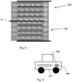
Fig. 9 shows schematically an electric or hybrid vehicle with an electric battery made of the battery module cells. -
Fig. 1 shows abattery cell module 10 with fivestackable battery components - Each
battery component anode 24, aseparator 28, acathode 26 and a bipolarcurrent collector 22. Each component also includes apolymer frame 20, which on aplanar side 124 has the bipolarcurrent collector 22 and on an oppositeplanar side 128 has theseparator 28.Polymer frame 20 in this embodiment is a polymer foil, and the attachment ofseparator 28 toframe 20 will be described in more detail with respect toFigs. 3a, 3b and 3c . -
Polymer frame 20 can be made for example of polypropylene (PP), polyethylene (PE), acrylnitrile butadiene-styrene (ABS), polyamide (PA), polylactic acid (PLA), poly (methyl methacrylate) (PMMA), polycarbonate (PC), polyethylene terephthalate (PET), polystyrene (PS), polyvinyl chloride (PVC), polyphenylene sulfide (PPS), polyphenylene oxide (PPO), Polyetherimide (PEI), polyether ether ketone (PEEK), polyether sulfone (PES), polybenzimidazole (PBI), nylon und composite foil or multilayer foil made of aluminum foil coated with a polymer for example polypropylene. Most preferably, the polymer frame is a PE/PP mixture. - The present invention uses solid-state electrolytes like lithium oxide or sulfide glasses or glass ceramics or ceramics as
separator 28. Liquid or gel electrolytes thus advantageously can be dispensed with, and the polymer frame can provide support for the more fragile separator material. Bipolarcurrent collector 22 can be made of copper or aluminum or nickel-coated aluminum or nickel for example.Anode 24 andcathode 26 can be deposited for example by vapor deposition or other film technology on bipolarcurrent collector 22. -
Fig. 2 shows a side view of the embodiment ofFig. 1 with ahousing 40 connected to the polymer frames 20 of thebattery components 11 to 15 to form a battery module cell. The housing can have for example four walls to cover each side of polymer frames 20, which preferably have a rectangular outer shape. -
Housing 40 may be made of the same material as polymer frames 20 for example, or of a different polymer material. - A
rod 99 as shown inFig. 1 can interact with feed holes in the polymer frames 20 as will be described, and can be removed after the stack is created and the housing is added. -
Figs. 3a, 3b and 3c show a top view of creation of the embodiment of the battery component of the present invention, andFig. 3d shows an alternate battery component with the bipolarcurrent collector 22 first connected to the polymer frame. -
Fig. 3a shows aside 128 of apolymer frame 20 with arectangular window 60. - As shown in
Fig. 3b ,frame 20 can be placed overseparator 28, which can have ananode 24 on one side andcathode 26 on the other side as shown inFig. 1 .Cathode 26 protrudes throughwindow 60, as shown inFig. 3c . Bipolarcurrent collector 22, which can be a thin metal foil, then can be added overcathode 26 and attached to theframe 20 at its edges.Frame 20 likewise is attached toseparator 28 aroundwindow 60. -
Frame 20 andseparator 28, fixedly connected, thus create an easilystackable battery component 98. Bipolarcurrent collector 22,anode 24 andcathode 26 can be connected to this stackable component as discussed above or also can added separately or later during assembly. - The anode and the cathode advantageously can be made of polymer, glass, glassceramic or ceramic solid-state materials, and the mechanical properties are improved and much of the mechanical stress during the cell assembly process can be retained by the polymer frame, which lowers the requirements on the assembly process. In addition, small imperfections at the solid-state material edges can be tolerated and the amount of defective goods can be decreased.
-
Fig. 3d shows an alternate embodiment which starts out with thesame frame 20 as inFig. 3a . Bipolarcurrent collector 22, which can be a thin foil of aluminum coated with nickel, is placed nickel side down on the frame to overlapside 128. Gluing or other bonding can be used to attach the nickel coating to a PP/PE frame, which advantageously provides a stable connection compares to a PP/PE aluminum or copper connection. The thin foil of thecurrent collector 22 is also stabilized well, and then thecathode 26,separator 28 andanode 24 can be added separately to the combinedframe 20/current collector 22 component. -
Figs. 4a, 4b, 4c, 4d, 4e and 4f show various frame geometries of the polymer frames according to the present invention, withFig. 4a being similar toFig. 3a , and frames 201, 202, 203, 204, 205 having awindow 301 with rounded edges, acircular window 302, awindow 303 similar towindow 301 but smaller for a same outer sized frame, a perfectlysquare window 304 and anoval window 305, respectively. -
Fig. 4g shows apolymer frame 206 with for example fourwindows -
Fig. 5 shows apolymer frame 203 according to the present invention withfeed holes 305 for easing assembly. - Assembly of the
Fig.1 embodiment can occur as follows: endplate anodecurrent collector 92 is provided, and thenbattery component 11 is added so thatframe 20 is slid overrod 99 via afeed hole 305.Polymer frame 20 can be slid over further rods via feed holes 305.Components rod 99 as shown inFig. 1 , and finallycathode top plate 90 added to create thebattery module 10. Theanode 24 of abattery component current collector 22 of thebattery component - To create the
Fig. 2 embodiment therod 99 can be removed andhousing 40 sides can be added and attached to the polymer frames. -
Fig. 6 shows a battery with two modules, thetop module 120 being similar tomodule 10 but having a plate or tab at the anode side extending in a different lateral direction, this plate being a so-calledmiddle plate 94. The bottom frame oftop module 120 can be omitted. Thebottom module 130 can simply be the inverse, with an anode extending through a window contacting themiddle plate 94 and the frames bonded together with the middle plate ortab 94 extending, preferably on a side opposite the cathode end plates. As an alternative, the end plates can be anode end plates and the cathode can extend in the middle. - Different battery modules with different endplate configurations advantageously can be created, and then connected in series or in parallel to create different battery capacities or voltages. Specifically, a battery module with simply one endplate at an end of the housing, either a cathode or anode endplate, can be created, identified herein as a module EP, the endplate preferably extending laterally past the housing. For parallel connection with such a module EP, a so-called module EMP with one endplate and one middle plate connector, extending laterally from another side of the housing as the endplate, can be created. A module MP with solely one middle plate and no other endplate, and a module TMP with two middle plates can also be created. These modules, EP, EMP, MP and TMP can be combined in series or parallel to create different battery capacities and voltages. The bipolar current collectors can weld together, as can the frames at the connections.
-
Fig. 6 thus shows a EMP/EP combination. -
Fig. 7 for example shows two modules EP in series with the frame bonded at a weld 210, and anextra end plate 190 to create a higher voltage battery. -
Fig. 8 shows schematically a further battery configuration with two EP modules and a TMP module in the middle. Other configurations such as EP/MP/EMP or EP/MP/TMP/EP are also possible. - As shown in
Fig. 9 , in one application, the battery cell module or stack 110 can be created for example with a much larger number of battery cells for providing power as an electric battery to anelectric motor 200 for powering anelectric vehicle 300. - By using the bipolar current collector foil with the solid state separator material as above, several advantages result. In electric and hybrid vehicles, the external wiring of the cells is sophisticated and expensive. For example, the battery pack of s prior art eGolf consists of 22 modules with each 12 cells. The weight of the electrical wires and cell connectors contributes significantly to the cell weight and the costs of the battery pack. The weight and the costs depends strongly on the amount of current. Increasing voltage via an internal series connection as in the present invention, without wiring, helps to reduce the amount of copper wires/connectors. Also, the internal series connection of electrodes without wiring as in the present invention allows to build cells with very different voltages. Cells with nominal voltages around 12 volts, 24 volts, 48 volts up to 800 volts are preferred. These cells then can be connected in parallel or in series as desired, as described above.
- Even pure aluminum foil can used as bipolar current collector material. The bipolar current collector is thinner than in a conventional lithium-ion battery and parallel connection of electrodes internally leads to cost and weight reduction due to use of Al current collectors and less tabs in the cell.
- Further, solid-state lithium cells also allow for the usage of aluminum foil as anode current collector foil, which may not be possible for conventional lithium ion cells due to lithium intercalation reaction into the aluminum, which causes cracking and corrosion of the aluminum.
- While with a solid-electrolyte (ceramic or polymer) there may be a surface reaction with the aluminum, without of a liquid phase present, no Al3+ will or can be dissolve and migrate to the cathode. For even better corrosion prevention, carbon or nickel coated aluminum foil may be advantageous as the material for the current collector bipolar plate. In the prior art, a small short circuit between cathode and anode can has a big impact on the battery cell and its module. If one cell in a 4 series/3 parallel module-system, like the eGolf module, has a short circuit failure, a series of four battery cells will cut off; the result is a capacity loss of 33.3%. The remaining eight cells receive a 50% higher stress. The likelihood of the faster aging of this module is much high. A module-failure then would lead to a complete battery-system failure because all modules are serial connected.
- In the present invention, the battery can be made of a couple up to hundreds of small battery cells. For example, a module cell is made of 140 cells of 10∗15 cm electrode size, with 3.7 V per cell gives 518 V as the module cell voltage with a capacity of 0.45 Ah, and has similar energy to a classic 63 Ah, 3.7 V cell. However, the module cells are the parallel-connected cells, for example one module cell in serial and 12 in parallel. The same failure (short circuit of anode and cathode) in this battery would lead to a capacity loss of just 0.71% and in the case of a failure of a whole module, a capacity loss of 8.3%. Another advantage is that all module cells are parallel connected so that even if several malfunction, there is a loss in the battery capacity but never a shutdown of the whole battery-system.
- The present invention also enhances the manufacturing speed of high-voltage and ultra-high-voltage modules with additionally supporting the high-voltage and ultra-high-voltage module cells to get more shock/vibration resistance for the use in a horizontal or vertical battery position.
- The frame-supported separators do not just increase the speed of stacking the single battery cells to a module cell, further those frames can be used for fixing the stack (module cell) for transport and build/assemble modules faster. After stacking all single battery cells can, with the help of the frames, be glued, welded or laminated together without moving the stack. This stabilizes the stack/module cell; all cells remain their positions; immediately without moving the stack into an extra cell housing.
- Depending of the module the bunch of module cells can assembled without internal wiring, this can be achieved with double-coated electrode (only with anode or cathode material). This double- coated electrode or middle plate has the function of an "end plate" for two module cells and this middle plate connect both module cells with each other. This reduces the assembling time by stacking the module cells to a module also the internal wiring. The production time for a module will be decrease.
- A further advantage of the sealed module cell is the flexible polymer-frame, which stabilizes the each single battery cell and reduces the vibration force by absorbing energy through swinging. With the polymer frame, each fragile separator has its own suspension to lower the vibration/shock force.
Claims (10)
- A battery unit comprising:a polymer frame (20) having an outer shape, a window (60) arranged within the outer shape, a planar side (124) and an opposite planar side (128), wherein the planar side (124) and the opposite planar side (128) are parallel to each other and perpendicular to the outer shape and the window of the polymer frame;a bipolar current collector foil (22), the bipolar current collector foil being fixedly connected to the planar side (124) of the polymer frame (20) at its edges around the window (60);a separator (28) including a solid-state electrolyte, the separator (28) being fixedly connected to the opposite planar side (128) of the polymer frame at its edges around the window (60);a cathode (26) deposited as a film on a first side of the bipolar current collector foil (22) or on the separator (28); andan anode (24).
- The battery unit as recited in claim 1, wherein the cathode (26) is deposited on the bipolar current collector foil (22).
- The battery unit as recited in claim 2, wherein the anode (24) is deposited as a film on a second side of the bipolar current collector foil opposite the first side.
- The battery unit as recited in any of the preceding claims, wherein a thickness of the bipolar current collector foil (22) is smaller than 15 micrometers.
- The battery unit as recited in any of the preceding claims, wherein the bipolar current collector foil (22) is attached to the polymer frame (20) by gluing, welding heat bonding, lamination or adhesive tape.
- The battery unit as recited in any of the preceding claims, wherein the bipolar current collector foil (22) is made of aluminum foil coated with nickel, and the nickel is attached directly to the frame.
- The battery unit as recited in any of the preceding claims, wherein the separator is made of lithium oxide or sulfide glasses or glass ceramics or ceramics.
- A battery module comprising a plurality of the battery units as recited in any of the preceding claims connected in series.
- An electric vehicle battery comprising a plurality of the battery modules as recited in claim 8, connected in series or in parallel.
- An electric vehicle comprising the battery as recited in claim 9.
Applications Claiming Priority (2)
| Application Number | Priority Date | Filing Date | Title |
|---|---|---|---|
| US15/432,328 US11362338B2 (en) | 2017-02-14 | 2017-02-14 | Electric vehicle battery cell with solid state electrolyte |
| PCT/IB2018/000333 WO2018150277A1 (en) | 2017-02-14 | 2018-02-12 | Electric vehicle battery cell with solid state electrolyte |
Publications (2)
| Publication Number | Publication Date |
|---|---|
| EP3583639A1 EP3583639A1 (en) | 2019-12-25 |
| EP3583639B1 true EP3583639B1 (en) | 2023-11-01 |
Family
ID=62002159
Family Applications (1)
| Application Number | Title | Priority Date | Filing Date |
|---|---|---|---|
| EP18718189.6A Active EP3583639B1 (en) | 2017-02-14 | 2018-02-12 | Electric vehicle battery cell with solid state electrolyte |
Country Status (4)
| Country | Link |
|---|---|
| US (1) | US11362338B2 (en) |
| EP (1) | EP3583639B1 (en) |
| CN (1) | CN110402502B (en) |
| WO (1) | WO2018150277A1 (en) |
Families Citing this family (9)
| Publication number | Priority date | Publication date | Assignee | Title |
|---|---|---|---|---|
| US10797284B2 (en) | 2017-02-14 | 2020-10-06 | Volkswagen Ag | Electric vehicle battery cell with polymer frame for battery cell components |
| US11870028B2 (en) | 2017-02-14 | 2024-01-09 | Volkswagen Ag | Electric vehicle battery cell with internal series connection stacking |
| US11362371B2 (en) | 2017-02-14 | 2022-06-14 | Volkswagen Ag | Method for manufacturing electric vehicle battery cells with polymer frame support |
| US11888178B2 (en) * | 2018-09-10 | 2024-01-30 | Volkswagen Ag | Method for producing an electric battery with separator material on a current collector base |
| DE102019216545A1 (en) * | 2019-10-28 | 2021-04-29 | Volkswagen Aktiengesellschaft | High-voltage battery of a motor vehicle |
| CN112768811B (en) * | 2019-11-01 | 2024-09-24 | 通用汽车环球科技运作有限责任公司 | Capacitor-assisted electrochemical device with hybrid architecture |
| DE102020209759A1 (en) | 2020-08-03 | 2022-02-03 | Volkswagen Aktiengesellschaft | high-voltage cell |
| US12244037B2 (en) | 2021-07-09 | 2025-03-04 | Lg Energy Solution, Ltd. | Manufacturing method for electrode assembly |
| US20250158113A1 (en) * | 2022-02-18 | 2025-05-15 | Northeastern University | Sulfide Based All-Solid-State Batteries Enabled by Bipolar Stacking |
Citations (2)
| Publication number | Priority date | Publication date | Assignee | Title |
|---|---|---|---|---|
| US20110014520A1 (en) * | 2008-07-25 | 2011-01-20 | Tomohiro Ueda | Bipolar battery |
| US20140349147A1 (en) * | 2011-10-24 | 2014-11-27 | Advanced Battery Concepts, LLC | Bipolar battery assembly |
Family Cites Families (76)
| Publication number | Priority date | Publication date | Assignee | Title |
|---|---|---|---|---|
| US3819412A (en) * | 1972-02-07 | 1974-06-25 | Tyco Laboratories Inc | Plates for lead acid batteries |
| US4164068A (en) * | 1977-08-18 | 1979-08-14 | Exxon Research & Engineering Co. | Method of making bipolar carbon-plastic electrode structure-containing multicell electrochemical device |
| US4539268A (en) | 1981-07-02 | 1985-09-03 | California Institute Of Technology | Sealed bipolar multi-cell battery |
| DE3340264A1 (en) | 1983-11-08 | 1985-05-15 | Brown, Boveri & Cie Ag, 6800 Mannheim | ELECTROCHEMICAL STORAGE CELL |
| GB8509957D0 (en) | 1985-04-18 | 1985-05-30 | Ici Plc | Electrode |
| US5162172A (en) | 1990-12-14 | 1992-11-10 | Arch Development Corporation | Bipolar battery |
| US5618641A (en) * | 1993-12-03 | 1997-04-08 | Bipolar Power Corporation | Bipolar battery construction |
| US5518839A (en) | 1995-04-12 | 1996-05-21 | Olsen; Ib I. | Current collector for solid electrochemical cell |
| US5688615A (en) | 1995-11-03 | 1997-11-18 | Globe-Union, Inc. | Bipolar battery and method of making same |
| GB9607398D0 (en) | 1996-04-10 | 1996-06-12 | Nat Power Plc | Process for the fabrication of electrochemical cell components |
| JP4038699B2 (en) | 1996-12-26 | 2008-01-30 | 株式会社ジーエス・ユアサコーポレーション | Lithium ion battery |
| US5910378A (en) | 1997-10-10 | 1999-06-08 | Minnesota Mining And Manufacturing Company | Membrane electrode assemblies |
| CN1180506C (en) | 1999-03-26 | 2004-12-15 | 松下电器产业株式会社 | laminated sheet packaged battery |
| KR100515571B1 (en) | 2000-02-08 | 2005-09-20 | 주식회사 엘지화학 | Stacked electrochemical cell |
| SG103298A1 (en) | 2000-06-16 | 2004-04-29 | Nisshin Spinning | Polymer battery and method of manufacture |
| US6752842B2 (en) | 2001-06-18 | 2004-06-22 | Power Paper Ltd. | Manufacture of flexible thin layer electrochemical cell |
| SE520007C8 (en) | 2001-09-19 | 2006-05-16 | Nilar Europ Ab | A bipolar battery, a method of manufacturing a bipolar battery and car plate composition |
| US6908711B2 (en) | 2002-04-10 | 2005-06-21 | Pacific Lithium New Zealand Limited | Rechargeable high power electrochemical device |
| JP4144312B2 (en) | 2002-10-08 | 2008-09-03 | 日産自動車株式会社 | Bipolar battery |
| JP4135473B2 (en) | 2002-11-07 | 2008-08-20 | 日産自動車株式会社 | Bipolar battery |
| US7195690B2 (en) | 2003-05-28 | 2007-03-27 | 3M Innovative Properties Company | Roll-good fuel cell fabrication processes, equipment, and articles produced from same |
| JP4238645B2 (en) | 2003-06-12 | 2009-03-18 | 日産自動車株式会社 | Bipolar battery |
| JP3972884B2 (en) | 2003-10-10 | 2007-09-05 | 日産自動車株式会社 | Assembled battery |
| JP2005259379A (en) | 2004-03-09 | 2005-09-22 | Nissan Motor Co Ltd | Bipolar battery |
| US8345988B2 (en) * | 2004-06-22 | 2013-01-01 | Sri International | Method and apparatus for recognizing 3-D objects |
| JP5098150B2 (en) | 2004-12-07 | 2012-12-12 | 日産自動車株式会社 | Bipolar battery and manufacturing method thereof |
| US8076021B2 (en) | 2004-12-10 | 2011-12-13 | Nissan Motor Co., Ltd. | Bipolar battery |
| FR2879824A1 (en) * | 2004-12-16 | 2006-06-23 | Snecma Moteurs Sa | BIPOLAR PLATE FOR FUEL CELL |
| BRPI0614743A2 (en) | 2005-08-09 | 2011-04-12 | Polyplus Battery Co Inc | flexible sealing frames for protected active metal anodes |
| CN1912522A (en) | 2005-08-10 | 2007-02-14 | 李建新 | Radiator suitable for aluminium alloy cavity nickel coated anti-corrosion |
| US7553582B2 (en) | 2005-09-06 | 2009-06-30 | Oak Ridge Micro-Energy, Inc. | Getters for thin film battery hermetic package |
| JP5286650B2 (en) | 2006-07-19 | 2013-09-11 | トヨタ自動車株式会社 | Secondary battery |
| US20090092903A1 (en) | 2007-08-29 | 2009-04-09 | Johnson Lonnie G | Low Cost Solid State Rechargeable Battery and Method of Manufacturing Same |
| JP5205920B2 (en) | 2007-11-01 | 2013-06-05 | 日産自動車株式会社 | Bipolar battery manufacturing method and manufacturing apparatus |
| KR20120002519A (en) | 2008-10-29 | 2012-01-05 | 세람테크 게엠베하 | Separation layer for separating anode and cathode in lithium ion accumulators or batteries |
| JP5381078B2 (en) | 2008-12-19 | 2014-01-08 | 日産自動車株式会社 | Electrode and manufacturing method thereof |
| KR20120016252A (en) | 2009-04-24 | 2012-02-23 | 지4 시너제틱스 인크. | Energy storage device with monopole and dipole cells electrically coupled in series and in parallel |
| JP2010277811A (en) | 2009-05-28 | 2010-12-09 | Abe Tomomi | Cell unit of redox flow battery and its cell stack structure |
| JP5504708B2 (en) * | 2009-06-25 | 2014-05-28 | 日産自動車株式会社 | Bipolar secondary battery |
| DE102009027346A1 (en) * | 2009-06-30 | 2011-01-05 | Robert Bosch Gmbh | Method and electrical circuit for operating an electric motor, in particular a servomotor for a component of an internal combustion engine |
| GB2477552B (en) | 2010-02-08 | 2016-01-27 | Qinetiq Ltd | Thin electrochemical cell |
| DE102010013031A1 (en) | 2010-03-26 | 2011-09-29 | Daimler Ag | Battery e.g. lithium-ion high-voltage battery, used in e.g. hybrid car, has electrical isolating frame formed between metal sheets, and electrical isolating spacer element arranged at frame among deformed regions of sheets |
| DE102010018731A1 (en) | 2010-04-29 | 2011-11-03 | Li-Tec Battery Gmbh | Lithium-sulfur battery |
| WO2011158948A1 (en) | 2010-06-18 | 2011-12-22 | Semiconductor Energy Laboratory Co., Ltd. | Method of manufacturing power storage device |
| DE102010031543A1 (en) | 2010-07-20 | 2012-01-26 | Evonik Litarion Gmbh | Battery containing a bimetal |
| FR2964256B1 (en) * | 2010-08-24 | 2012-09-28 | Commissariat Energie Atomique | BIPOLAR ELECTROCHEMICAL ACCUMULATOR WITH IMPROVED PACKAGING |
| US9368830B2 (en) | 2010-11-04 | 2016-06-14 | Samsung Sdi Co., Ltd. | Battery |
| DE102011003186A1 (en) | 2011-01-26 | 2012-07-26 | Evonik Degussa Gmbh | Thin, macroporous polymer films |
| WO2012124108A1 (en) | 2011-03-17 | 2012-09-20 | トヨタ自動車株式会社 | Solid-state battery and solid-state battery manufacturing method |
| FR2974674B1 (en) | 2011-04-26 | 2013-06-28 | Commissariat Energie Atomique | BIPOLAR LI-ION ELECTROCHEMICAL ACCUMULATOR WITH INCREASED CAPABILITY |
| JP2014517470A (en) | 2011-05-13 | 2014-07-17 | イースト ペン マニュファクチュアリング カンパニー | Composite current collector and method thereof |
| US9941546B2 (en) | 2011-09-09 | 2018-04-10 | East Penn Manufacturing Co., Inc. | Bipolar battery and plate |
| US9349542B2 (en) | 2011-12-21 | 2016-05-24 | Nanotek Instruments, Inc. | Stacks of internally connected surface-mediated cells and methods of operating same |
| JP2015509269A (en) | 2012-01-17 | 2015-03-26 | バラスト エナジー インコーポレイテッド | Electrodes and batteries |
| DE102012004161A1 (en) | 2012-03-05 | 2013-09-05 | Treofan Germany Gmbh & Co. Kg | Highly porous separator film with partial coating |
| DE102012213110B4 (en) | 2012-07-26 | 2016-12-01 | Leichtbau-Zentrum Sachsen Gmbh | Method for producing a film battery, method for preparing a film stack and lithium-ion battery element |
| KR101483239B1 (en) | 2012-08-30 | 2015-01-16 | 주식회사 엘지화학 | Packaging for a cable-type secondary battery and cable-type secondary battery including the same |
| CN103840212A (en) | 2012-11-23 | 2014-06-04 | 海洋王照明科技股份有限公司 | Making method of solid-state lithium ion battery |
| GB2512919B (en) * | 2013-04-12 | 2015-08-12 | Demetrios Georgiou Papadopoulos | Improvements in load release means for telescopic props |
| FR3006116B1 (en) | 2013-05-21 | 2015-06-26 | Commissariat Energie Atomique | BIPOLAR LI-ON BATTERY WITH IMPROVED SEALING AND METHOD OF MAKING THE SAME. |
| DE102013009629B4 (en) | 2013-06-10 | 2019-09-12 | Carl Freudenberg Kg | Electrode module and arrangement with electrode modules |
| CN103334147A (en) | 2013-06-24 | 2013-10-02 | 沈阳化工大学 | Method for preparing nickel-coated aluminum powder composite coating by utilizing pulse plating |
| US9484595B2 (en) * | 2013-08-15 | 2016-11-01 | Robert Bosch Gmbh | Li/metal battery with composite solid electrolyte |
| JP2017027652A (en) | 2013-12-05 | 2017-02-02 | 日立マクセル株式会社 | Non-aqueous electrolyte secondary battery and manufacturing method thereof |
| JP6571091B2 (en) * | 2013-12-30 | 2019-09-04 | グリッドテンシャル エナジー インコーポレイテッドGridtential Energy,Inc. | Sealed bipolar battery assembly and manufacturing method thereof |
| US20150280177A1 (en) | 2014-03-28 | 2015-10-01 | Intel Corporation | Method for providing a sealing compound on a battery cell |
| US20180013185A1 (en) | 2014-10-06 | 2018-01-11 | Eos Energy Storage, Llc | Electrolyte for rechargeable electrochemical cell |
| DE102015210806A1 (en) | 2014-11-14 | 2016-05-19 | Hyundai Motor Company | Bipolar electrode, bipolar all-solid-state battery manufactured using same, and manufacturing method thereof |
| US10147968B2 (en) | 2014-12-02 | 2018-12-04 | Polyplus Battery Company | Standalone sulfide based lithium ion-conducting glass solid electrolyte and associated structures, cells and methods |
| CN108028411A (en) | 2015-08-21 | 2018-05-11 | 住友电气工业株式会社 | Frame body, cell frame for redox flow battery, and redox flow battery |
| WO2017136545A1 (en) | 2016-02-02 | 2017-08-10 | Research Foundation Of The City University Of New York | Rechargeable alkaline manganese dioxide-zinc bipolar batteries |
| US10147957B2 (en) | 2016-04-07 | 2018-12-04 | Lockheed Martin Energy, Llc | Electrochemical cells having designed flow fields and methods for producing the same |
| US10381674B2 (en) | 2016-04-07 | 2019-08-13 | Lockheed Martin Energy, Llc | High-throughput manufacturing processes for making electrochemical unit cells and electrochemical unit cells produced using the same |
| US11870028B2 (en) | 2017-02-14 | 2024-01-09 | Volkswagen Ag | Electric vehicle battery cell with internal series connection stacking |
| US10797284B2 (en) | 2017-02-14 | 2020-10-06 | Volkswagen Ag | Electric vehicle battery cell with polymer frame for battery cell components |
| US11362371B2 (en) | 2017-02-14 | 2022-06-14 | Volkswagen Ag | Method for manufacturing electric vehicle battery cells with polymer frame support |
-
2017
- 2017-02-14 US US15/432,328 patent/US11362338B2/en active Active
-
2018
- 2018-02-12 CN CN201880011689.4A patent/CN110402502B/en active Active
- 2018-02-12 EP EP18718189.6A patent/EP3583639B1/en active Active
- 2018-02-12 WO PCT/IB2018/000333 patent/WO2018150277A1/en not_active Ceased
Patent Citations (2)
| Publication number | Priority date | Publication date | Assignee | Title |
|---|---|---|---|---|
| US20110014520A1 (en) * | 2008-07-25 | 2011-01-20 | Tomohiro Ueda | Bipolar battery |
| US20140349147A1 (en) * | 2011-10-24 | 2014-11-27 | Advanced Battery Concepts, LLC | Bipolar battery assembly |
Also Published As
| Publication number | Publication date |
|---|---|
| EP3583639A1 (en) | 2019-12-25 |
| CN110402502B (en) | 2024-07-19 |
| US11362338B2 (en) | 2022-06-14 |
| WO2018150277A1 (en) | 2018-08-23 |
| CN110402502A (en) | 2019-11-01 |
| US20180233752A1 (en) | 2018-08-16 |
Similar Documents
| Publication | Publication Date | Title |
|---|---|---|
| EP3583639B1 (en) | Electric vehicle battery cell with solid state electrolyte | |
| EP3583651B1 (en) | Electric vehicle battery cell with internal series connection stacking | |
| EP3583652B1 (en) | Electric vehicle battery cell with polymer frame for battery cell components | |
| US8472164B2 (en) | Stacking type electrochemical cell having quasi-bipolar structure | |
| EP3583640B1 (en) | Method for manufacturing electric vehicle battery cells with polymer frame support | |
| KR102401809B1 (en) | Method for manufacturing an electrode unit for a battery cell, and an electrode unit | |
| JP6836631B2 (en) | Horizontal composite power supply structure | |
| KR20200068019A (en) | Composite battery cell | |
| KR20150034611A (en) | Pouch type secondary battery | |
| KR20220002540A (en) | cell battery | |
| JP2002353078A (en) | Multilayer electric double layer capacitor module | |
| KR20180060763A (en) | Battery pack improved in fixing structure of cell lead | |
| US11978873B2 (en) | Battery module with cooling cartridge and battery system thereof | |
| KR101746628B1 (en) | Battery Cell Providing Suppressed Exposure of Electrode and Method for Manufacturing the Same | |
| CN120359659A (en) | Battery pack and method for manufacturing same | |
| CN120322905A (en) | Battery pack and method of manufacturing the same | |
| KR20170086349A (en) | Battery cell and manufacturing method thereof | |
| CN115117497A (en) | Battery module with heat dissipation box body and battery system thereof | |
| EP2523202A1 (en) | Electrical double - layer capacitor, and method for manufacturing such a capacitor |
Legal Events
| Date | Code | Title | Description |
|---|---|---|---|
| STAA | Information on the status of an ep patent application or granted ep patent |
Free format text: STATUS: UNKNOWN |
|
| STAA | Information on the status of an ep patent application or granted ep patent |
Free format text: STATUS: THE INTERNATIONAL PUBLICATION HAS BEEN MADE |
|
| PUAI | Public reference made under article 153(3) epc to a published international application that has entered the european phase |
Free format text: ORIGINAL CODE: 0009012 |
|
| STAA | Information on the status of an ep patent application or granted ep patent |
Free format text: STATUS: REQUEST FOR EXAMINATION WAS MADE |
|
| 17P | Request for examination filed |
Effective date: 20190913 |
|
| AK | Designated contracting states |
Kind code of ref document: A1 Designated state(s): AL AT BE BG CH CY CZ DE DK EE ES FI FR GB GR HR HU IE IS IT LI LT LU LV MC MK MT NL NO PL PT RO RS SE SI SK SM TR |
|
| AX | Request for extension of the european patent |
Extension state: BA ME |
|
| RIN1 | Information on inventor provided before grant (corrected) |
Inventor name: SCHEFFLER, ROUVEN Inventor name: HERMANN, MIRKO Inventor name: SPEIDEL, ANGELA |
|
| DAV | Request for validation of the european patent (deleted) | ||
| DAX | Request for extension of the european patent (deleted) | ||
| STAA | Information on the status of an ep patent application or granted ep patent |
Free format text: STATUS: EXAMINATION IS IN PROGRESS |
|
| 17Q | First examination report despatched |
Effective date: 20200827 |
|
| REG | Reference to a national code |
Ref legal event code: R079 Ipc: H01M0004660000 Ref country code: DE Ref legal event code: R079 Ref document number: 602018060338 Country of ref document: DE Free format text: PREVIOUS MAIN CLASS: H01M0002020000 Ipc: H01M0004660000 |
|
| RIC1 | Information provided on ipc code assigned before grant |
Ipc: B60L 50/64 20190101ALI20230510BHEP Ipc: H01M 50/437 20210101ALI20230510BHEP Ipc: H01M 50/434 20210101ALI20230510BHEP Ipc: H01M 50/121 20210101ALI20230510BHEP Ipc: H01M 50/46 20210101ALI20230510BHEP Ipc: H01M 50/14 20210101ALI20230510BHEP Ipc: H01M 50/103 20210101ALI20230510BHEP Ipc: H01M 10/04 20060101ALI20230510BHEP Ipc: H01M 4/66 20060101AFI20230510BHEP |
|
| GRAP | Despatch of communication of intention to grant a patent |
Free format text: ORIGINAL CODE: EPIDOSNIGR1 |
|
| STAA | Information on the status of an ep patent application or granted ep patent |
Free format text: STATUS: GRANT OF PATENT IS INTENDED |
|
| P01 | Opt-out of the competence of the unified patent court (upc) registered |
Effective date: 20230529 |
|
| INTG | Intention to grant announced |
Effective date: 20230623 |
|
| GRAS | Grant fee paid |
Free format text: ORIGINAL CODE: EPIDOSNIGR3 |
|
| GRAA | (expected) grant |
Free format text: ORIGINAL CODE: 0009210 |
|
| STAA | Information on the status of an ep patent application or granted ep patent |
Free format text: STATUS: THE PATENT HAS BEEN GRANTED |
|
| AK | Designated contracting states |
Kind code of ref document: B1 Designated state(s): AL AT BE BG CH CY CZ DE DK EE ES FI FR GB GR HR HU IE IS IT LI LT LU LV MC MK MT NL NO PL PT RO RS SE SI SK SM TR |
|
| REG | Reference to a national code |
Ref country code: GB Ref legal event code: FG4D |
|
| REG | Reference to a national code |
Ref country code: CH Ref legal event code: EP |
|
| REG | Reference to a national code |
Ref country code: IE Ref legal event code: FG4D |
|
| REG | Reference to a national code |
Ref country code: DE Ref legal event code: R096 Ref document number: 602018060338 Country of ref document: DE |
|
| REG | Reference to a national code |
Ref country code: LT Ref legal event code: MG9D |
|
| REG | Reference to a national code |
Ref country code: NL Ref legal event code: MP Effective date: 20231101 |
|
| PG25 | Lapsed in a contracting state [announced via postgrant information from national office to epo] |
Ref country code: GR Free format text: LAPSE BECAUSE OF FAILURE TO SUBMIT A TRANSLATION OF THE DESCRIPTION OR TO PAY THE FEE WITHIN THE PRESCRIBED TIME-LIMIT Effective date: 20240202 |
|
| PG25 | Lapsed in a contracting state [announced via postgrant information from national office to epo] |
Ref country code: IS Free format text: LAPSE BECAUSE OF FAILURE TO SUBMIT A TRANSLATION OF THE DESCRIPTION OR TO PAY THE FEE WITHIN THE PRESCRIBED TIME-LIMIT Effective date: 20240301 |
|
| PG25 | Lapsed in a contracting state [announced via postgrant information from national office to epo] |
Ref country code: LT Free format text: LAPSE BECAUSE OF FAILURE TO SUBMIT A TRANSLATION OF THE DESCRIPTION OR TO PAY THE FEE WITHIN THE PRESCRIBED TIME-LIMIT Effective date: 20231101 |
|
| REG | Reference to a national code |
Ref country code: AT Ref legal event code: MK05 Ref document number: 1628259 Country of ref document: AT Kind code of ref document: T Effective date: 20231101 |
|
| PG25 | Lapsed in a contracting state [announced via postgrant information from national office to epo] |
Ref country code: NL Free format text: LAPSE BECAUSE OF FAILURE TO SUBMIT A TRANSLATION OF THE DESCRIPTION OR TO PAY THE FEE WITHIN THE PRESCRIBED TIME-LIMIT Effective date: 20231101 |
|
| PG25 | Lapsed in a contracting state [announced via postgrant information from national office to epo] |
Ref country code: AT Free format text: LAPSE BECAUSE OF FAILURE TO SUBMIT A TRANSLATION OF THE DESCRIPTION OR TO PAY THE FEE WITHIN THE PRESCRIBED TIME-LIMIT Effective date: 20231101 |
|
| PG25 | Lapsed in a contracting state [announced via postgrant information from national office to epo] |
Ref country code: ES Free format text: LAPSE BECAUSE OF FAILURE TO SUBMIT A TRANSLATION OF THE DESCRIPTION OR TO PAY THE FEE WITHIN THE PRESCRIBED TIME-LIMIT Effective date: 20231101 |
|
| PG25 | Lapsed in a contracting state [announced via postgrant information from national office to epo] |
Ref country code: NL Free format text: LAPSE BECAUSE OF FAILURE TO SUBMIT A TRANSLATION OF THE DESCRIPTION OR TO PAY THE FEE WITHIN THE PRESCRIBED TIME-LIMIT Effective date: 20231101 Ref country code: LT Free format text: LAPSE BECAUSE OF FAILURE TO SUBMIT A TRANSLATION OF THE DESCRIPTION OR TO PAY THE FEE WITHIN THE PRESCRIBED TIME-LIMIT Effective date: 20231101 Ref country code: IS Free format text: LAPSE BECAUSE OF FAILURE TO SUBMIT A TRANSLATION OF THE DESCRIPTION OR TO PAY THE FEE WITHIN THE PRESCRIBED TIME-LIMIT Effective date: 20240301 Ref country code: GR Free format text: LAPSE BECAUSE OF FAILURE TO SUBMIT A TRANSLATION OF THE DESCRIPTION OR TO PAY THE FEE WITHIN THE PRESCRIBED TIME-LIMIT Effective date: 20240202 Ref country code: ES Free format text: LAPSE BECAUSE OF FAILURE TO SUBMIT A TRANSLATION OF THE DESCRIPTION OR TO PAY THE FEE WITHIN THE PRESCRIBED TIME-LIMIT Effective date: 20231101 Ref country code: BG Free format text: LAPSE BECAUSE OF FAILURE TO SUBMIT A TRANSLATION OF THE DESCRIPTION OR TO PAY THE FEE WITHIN THE PRESCRIBED TIME-LIMIT Effective date: 20240201 Ref country code: AT Free format text: LAPSE BECAUSE OF FAILURE TO SUBMIT A TRANSLATION OF THE DESCRIPTION OR TO PAY THE FEE WITHIN THE PRESCRIBED TIME-LIMIT Effective date: 20231101 Ref country code: PT Free format text: LAPSE BECAUSE OF FAILURE TO SUBMIT A TRANSLATION OF THE DESCRIPTION OR TO PAY THE FEE WITHIN THE PRESCRIBED TIME-LIMIT Effective date: 20240301 |
|
| PG25 | Lapsed in a contracting state [announced via postgrant information from national office to epo] |
Ref country code: SE Free format text: LAPSE BECAUSE OF FAILURE TO SUBMIT A TRANSLATION OF THE DESCRIPTION OR TO PAY THE FEE WITHIN THE PRESCRIBED TIME-LIMIT Effective date: 20231101 Ref country code: RS Free format text: LAPSE BECAUSE OF FAILURE TO SUBMIT A TRANSLATION OF THE DESCRIPTION OR TO PAY THE FEE WITHIN THE PRESCRIBED TIME-LIMIT Effective date: 20231101 Ref country code: PL Free format text: LAPSE BECAUSE OF FAILURE TO SUBMIT A TRANSLATION OF THE DESCRIPTION OR TO PAY THE FEE WITHIN THE PRESCRIBED TIME-LIMIT Effective date: 20231101 Ref country code: NO Free format text: LAPSE BECAUSE OF FAILURE TO SUBMIT A TRANSLATION OF THE DESCRIPTION OR TO PAY THE FEE WITHIN THE PRESCRIBED TIME-LIMIT Effective date: 20240201 Ref country code: LV Free format text: LAPSE BECAUSE OF FAILURE TO SUBMIT A TRANSLATION OF THE DESCRIPTION OR TO PAY THE FEE WITHIN THE PRESCRIBED TIME-LIMIT Effective date: 20231101 Ref country code: HR Free format text: LAPSE BECAUSE OF FAILURE TO SUBMIT A TRANSLATION OF THE DESCRIPTION OR TO PAY THE FEE WITHIN THE PRESCRIBED TIME-LIMIT Effective date: 20231101 |
|
| PG25 | Lapsed in a contracting state [announced via postgrant information from national office to epo] |
Ref country code: DK Free format text: LAPSE BECAUSE OF FAILURE TO SUBMIT A TRANSLATION OF THE DESCRIPTION OR TO PAY THE FEE WITHIN THE PRESCRIBED TIME-LIMIT Effective date: 20231101 |
|
| PG25 | Lapsed in a contracting state [announced via postgrant information from national office to epo] |
Ref country code: CZ Free format text: LAPSE BECAUSE OF FAILURE TO SUBMIT A TRANSLATION OF THE DESCRIPTION OR TO PAY THE FEE WITHIN THE PRESCRIBED TIME-LIMIT Effective date: 20231101 |
|
| PG25 | Lapsed in a contracting state [announced via postgrant information from national office to epo] |
Ref country code: SK Free format text: LAPSE BECAUSE OF FAILURE TO SUBMIT A TRANSLATION OF THE DESCRIPTION OR TO PAY THE FEE WITHIN THE PRESCRIBED TIME-LIMIT Effective date: 20231101 |
|
| PG25 | Lapsed in a contracting state [announced via postgrant information from national office to epo] |
Ref country code: SM Free format text: LAPSE BECAUSE OF FAILURE TO SUBMIT A TRANSLATION OF THE DESCRIPTION OR TO PAY THE FEE WITHIN THE PRESCRIBED TIME-LIMIT Effective date: 20231101 Ref country code: SK Free format text: LAPSE BECAUSE OF FAILURE TO SUBMIT A TRANSLATION OF THE DESCRIPTION OR TO PAY THE FEE WITHIN THE PRESCRIBED TIME-LIMIT Effective date: 20231101 Ref country code: IT Free format text: LAPSE BECAUSE OF FAILURE TO SUBMIT A TRANSLATION OF THE DESCRIPTION OR TO PAY THE FEE WITHIN THE PRESCRIBED TIME-LIMIT Effective date: 20231101 Ref country code: EE Free format text: LAPSE BECAUSE OF FAILURE TO SUBMIT A TRANSLATION OF THE DESCRIPTION OR TO PAY THE FEE WITHIN THE PRESCRIBED TIME-LIMIT Effective date: 20231101 Ref country code: DK Free format text: LAPSE BECAUSE OF FAILURE TO SUBMIT A TRANSLATION OF THE DESCRIPTION OR TO PAY THE FEE WITHIN THE PRESCRIBED TIME-LIMIT Effective date: 20231101 Ref country code: CZ Free format text: LAPSE BECAUSE OF FAILURE TO SUBMIT A TRANSLATION OF THE DESCRIPTION OR TO PAY THE FEE WITHIN THE PRESCRIBED TIME-LIMIT Effective date: 20231101 |
|
| REG | Reference to a national code |
Ref country code: DE Ref legal event code: R097 Ref document number: 602018060338 Country of ref document: DE |
|
| PLBE | No opposition filed within time limit |
Free format text: ORIGINAL CODE: 0009261 |
|
| STAA | Information on the status of an ep patent application or granted ep patent |
Free format text: STATUS: NO OPPOSITION FILED WITHIN TIME LIMIT |
|
| PG25 | Lapsed in a contracting state [announced via postgrant information from national office to epo] |
Ref country code: MC Free format text: LAPSE BECAUSE OF FAILURE TO SUBMIT A TRANSLATION OF THE DESCRIPTION OR TO PAY THE FEE WITHIN THE PRESCRIBED TIME-LIMIT Effective date: 20231101 |
|
| REG | Reference to a national code |
Ref country code: CH Ref legal event code: PL |
|
| 26N | No opposition filed |
Effective date: 20240802 |
|
| PG25 | Lapsed in a contracting state [announced via postgrant information from national office to epo] |
Ref country code: LU Free format text: LAPSE BECAUSE OF NON-PAYMENT OF DUE FEES Effective date: 20240212 |
|
| PG25 | Lapsed in a contracting state [announced via postgrant information from national office to epo] |
Ref country code: CH Free format text: LAPSE BECAUSE OF NON-PAYMENT OF DUE FEES Effective date: 20240229 |
|
| PG25 | Lapsed in a contracting state [announced via postgrant information from national office to epo] |
Ref country code: SI Free format text: LAPSE BECAUSE OF FAILURE TO SUBMIT A TRANSLATION OF THE DESCRIPTION OR TO PAY THE FEE WITHIN THE PRESCRIBED TIME-LIMIT Effective date: 20231101 |
|
| PG25 | Lapsed in a contracting state [announced via postgrant information from national office to epo] |
Ref country code: SI Free format text: LAPSE BECAUSE OF FAILURE TO SUBMIT A TRANSLATION OF THE DESCRIPTION OR TO PAY THE FEE WITHIN THE PRESCRIBED TIME-LIMIT Effective date: 20231101 Ref country code: LU Free format text: LAPSE BECAUSE OF NON-PAYMENT OF DUE FEES Effective date: 20240212 Ref country code: CH Free format text: LAPSE BECAUSE OF NON-PAYMENT OF DUE FEES Effective date: 20240229 |
|
| REG | Reference to a national code |
Ref country code: BE Ref legal event code: MM Effective date: 20240229 |
|
| PG25 | Lapsed in a contracting state [announced via postgrant information from national office to epo] |
Ref country code: BE Free format text: LAPSE BECAUSE OF NON-PAYMENT OF DUE FEES Effective date: 20240229 |
|
| PG25 | Lapsed in a contracting state [announced via postgrant information from national office to epo] |
Ref country code: IE Free format text: LAPSE BECAUSE OF NON-PAYMENT OF DUE FEES Effective date: 20240212 |
|
| PG25 | Lapsed in a contracting state [announced via postgrant information from national office to epo] |
Ref country code: IE Free format text: LAPSE BECAUSE OF NON-PAYMENT OF DUE FEES Effective date: 20240212 Ref country code: BE Free format text: LAPSE BECAUSE OF NON-PAYMENT OF DUE FEES Effective date: 20240229 |
|
| PG25 | Lapsed in a contracting state [announced via postgrant information from national office to epo] |
Ref country code: RO Free format text: LAPSE BECAUSE OF FAILURE TO SUBMIT A TRANSLATION OF THE DESCRIPTION OR TO PAY THE FEE WITHIN THE PRESCRIBED TIME-LIMIT Effective date: 20231101 |
|
| PG25 | Lapsed in a contracting state [announced via postgrant information from national office to epo] |
Ref country code: CY Free format text: LAPSE BECAUSE OF FAILURE TO SUBMIT A TRANSLATION OF THE DESCRIPTION OR TO PAY THE FEE WITHIN THE PRESCRIBED TIME-LIMIT; INVALID AB INITIO Effective date: 20180212 |
|
| PG25 | Lapsed in a contracting state [announced via postgrant information from national office to epo] |
Ref country code: HU Free format text: LAPSE BECAUSE OF FAILURE TO SUBMIT A TRANSLATION OF THE DESCRIPTION OR TO PAY THE FEE WITHIN THE PRESCRIBED TIME-LIMIT; INVALID AB INITIO Effective date: 20180212 |
|
| PG25 | Lapsed in a contracting state [announced via postgrant information from national office to epo] |
Ref country code: FI Free format text: LAPSE BECAUSE OF FAILURE TO SUBMIT A TRANSLATION OF THE DESCRIPTION OR TO PAY THE FEE WITHIN THE PRESCRIBED TIME-LIMIT Effective date: 20231101 |
|
| PG25 | Lapsed in a contracting state [announced via postgrant information from national office to epo] |
Ref country code: TR Free format text: LAPSE BECAUSE OF FAILURE TO SUBMIT A TRANSLATION OF THE DESCRIPTION OR TO PAY THE FEE WITHIN THE PRESCRIBED TIME-LIMIT Effective date: 20231101 |
|
| PGFP | Annual fee paid to national office [announced via postgrant information from national office to epo] |
Ref country code: GB Payment date: 20260223 Year of fee payment: 9 |
|
| PGFP | Annual fee paid to national office [announced via postgrant information from national office to epo] |
Ref country code: DE Payment date: 20260228 Year of fee payment: 9 |
|
| PGFP | Annual fee paid to national office [announced via postgrant information from national office to epo] |
Ref country code: FR Payment date: 20260224 Year of fee payment: 9 |