EP3583584B1 - Method for operating a sensor arrangement on the basis of a dsi protocol and a corresponding sensor arrangement - Google Patents
Method for operating a sensor arrangement on the basis of a dsi protocol and a corresponding sensor arrangement Download PDFInfo
- Publication number
- EP3583584B1 EP3583584B1 EP18705894.6A EP18705894A EP3583584B1 EP 3583584 B1 EP3583584 B1 EP 3583584B1 EP 18705894 A EP18705894 A EP 18705894A EP 3583584 B1 EP3583584 B1 EP 3583584B1
- Authority
- EP
- European Patent Office
- Prior art keywords
- active sensor
- processing unit
- sensor units
- phase
- unit
- Prior art date
- Legal status (The legal status is an assumption and is not a legal conclusion. Google has not performed a legal analysis and makes no representation as to the accuracy of the status listed.)
- Active
Links
- 238000000034 method Methods 0.000 title claims description 29
- 238000012545 processing Methods 0.000 claims description 55
- 230000005540 biological transmission Effects 0.000 claims description 37
- 230000006854 communication Effects 0.000 claims description 14
- 238000004891 communication Methods 0.000 claims description 14
- 238000013480 data collection Methods 0.000 claims description 4
- 230000000737 periodic effect Effects 0.000 claims description 4
- 230000007175 bidirectional communication Effects 0.000 claims description 3
- 238000004146 energy storage Methods 0.000 claims 2
- 238000005259 measurement Methods 0.000 description 16
- 230000006870 function Effects 0.000 description 11
- 230000009131 signaling function Effects 0.000 description 9
- 238000012546 transfer Methods 0.000 description 5
- 239000003990 capacitor Substances 0.000 description 4
- 230000000694 effects Effects 0.000 description 3
- 238000011017 operating method Methods 0.000 description 3
- 238000013461 design Methods 0.000 description 2
- 230000007423 decrease Effects 0.000 description 1
- 230000001419 dependent effect Effects 0.000 description 1
- 238000010586 diagram Methods 0.000 description 1
- 238000004904 shortening Methods 0.000 description 1
- 230000001960 triggered effect Effects 0.000 description 1
Images


Classifications
-
- G—PHYSICS
- G08—SIGNALLING
- G08C—TRANSMISSION SYSTEMS FOR MEASURED VALUES, CONTROL OR SIMILAR SIGNALS
- G08C19/00—Electric signal transmission systems
-
- G—PHYSICS
- G01—MEASURING; TESTING
- G01S—RADIO DIRECTION-FINDING; RADIO NAVIGATION; DETERMINING DISTANCE OR VELOCITY BY USE OF RADIO WAVES; LOCATING OR PRESENCE-DETECTING BY USE OF THE REFLECTION OR RERADIATION OF RADIO WAVES; ANALOGOUS ARRANGEMENTS USING OTHER WAVES
- G01S13/00—Systems using the reflection or reradiation of radio waves, e.g. radar systems; Analogous systems using reflection or reradiation of waves whose nature or wavelength is irrelevant or unspecified
- G01S13/88—Radar or analogous systems specially adapted for specific applications
- G01S13/93—Radar or analogous systems specially adapted for specific applications for anti-collision purposes
- G01S13/931—Radar or analogous systems specially adapted for specific applications for anti-collision purposes of land vehicles
-
- G—PHYSICS
- G06—COMPUTING; CALCULATING OR COUNTING
- G06V—IMAGE OR VIDEO RECOGNITION OR UNDERSTANDING
- G06V20/00—Scenes; Scene-specific elements
- G06V20/50—Context or environment of the image
- G06V20/56—Context or environment of the image exterior to a vehicle by using sensors mounted on the vehicle
-
- H—ELECTRICITY
- H04—ELECTRIC COMMUNICATION TECHNIQUE
- H04L—TRANSMISSION OF DIGITAL INFORMATION, e.g. TELEGRAPHIC COMMUNICATION
- H04L12/00—Data switching networks
- H04L12/28—Data switching networks characterised by path configuration, e.g. LAN [Local Area Networks] or WAN [Wide Area Networks]
- H04L12/40—Bus networks
- H04L12/40006—Architecture of a communication node
- H04L12/40013—Details regarding a bus controller
-
- G—PHYSICS
- G01—MEASURING; TESTING
- G01S—RADIO DIRECTION-FINDING; RADIO NAVIGATION; DETERMINING DISTANCE OR VELOCITY BY USE OF RADIO WAVES; LOCATING OR PRESENCE-DETECTING BY USE OF THE REFLECTION OR RERADIATION OF RADIO WAVES; ANALOGOUS ARRANGEMENTS USING OTHER WAVES
- G01S13/00—Systems using the reflection or reradiation of radio waves, e.g. radar systems; Analogous systems using reflection or reradiation of waves whose nature or wavelength is irrelevant or unspecified
- G01S13/88—Radar or analogous systems specially adapted for specific applications
- G01S13/93—Radar or analogous systems specially adapted for specific applications for anti-collision purposes
- G01S13/931—Radar or analogous systems specially adapted for specific applications for anti-collision purposes of land vehicles
- G01S2013/9327—Sensor installation details
- G01S2013/93275—Sensor installation details in the bumper area
-
- H—ELECTRICITY
- H04—ELECTRIC COMMUNICATION TECHNIQUE
- H04L—TRANSMISSION OF DIGITAL INFORMATION, e.g. TELEGRAPHIC COMMUNICATION
- H04L12/00—Data switching networks
- H04L12/28—Data switching networks characterised by path configuration, e.g. LAN [Local Area Networks] or WAN [Wide Area Networks]
- H04L12/40—Bus networks
- H04L2012/40267—Bus for use in transportation systems
- H04L2012/40273—Bus for use in transportation systems the transportation system being a vehicle
Definitions
- the invention relates to a method for operating a sensor arrangement based on a DSI protocol in a motor vehicle and to a sensor arrangement in a motor vehicle that is operated by means of a method according to the invention.
- the DSI protocol ( Distributed System Interface, see: DSI3 Bus Standard, Revision 1.00 from February 16, 2011 ), the specification of which is hereby made part of this disclosure of this invention by explicit inclusion, is a protocol which allows a sensor network to be built on the basis of very simple two-wire cabling, in which a central entity (master) with one or more satellite entities (Slaves) communicated via a bus.
- the DSI protocol is primarily aimed at use in the vehicle in order to query and / or control a plurality of satellite entities, in particular sensors and actuators, by means of the central entity.
- a sensor arrangement comprising at least one central instance and at least one satellite instance, can be operated in one of two operating classes, on the one hand the "Signal Function Class” and on the other hand the "Power Function Class".
- the protocol also provides for three different types of use of the bus between the central instance and the satellite instance:
- CRM mode Common and Response mode
- the central instance sends a command to which the satellite instance responds (response). This is used, for example, to configure the satellite instances or to request specific values from a satellite instance.
- the satellite entities transmit comparatively large amounts of data to the central entity within a specified time slot, the transmission activity of the central entity being limited to a Synchronization signal (Broadcast Read Command) to provide the satellite entities with a reference point for determining this time slot.
- the satellite entities have already been provided with information on their respective time slot beforehand, so that they can determine their respective transmission time interval in response to the synchronization signal and, on the basis of this, can send their sensor data to the central entity.
- the "signal function class" mentioned at the beginning according to the above specification is primarily used to connect sensor satellite entities with a low energy requirement and a comparatively high volume of data that is to be sent from the satellite entity to the central entity.
- a phase of communication in CRM mode takes place between the central entity and the satellite entity, during which the satellite entity is usually configured, for example with regard to the parameters of the above-mentioned PDCM timeslot Satellite instance.
- the sensor arrangement switches to PCDM mode, in which the sensor satellite entity or the sensor satellite entities always send the recorded data in the assigned time slot to the central entity in response to the synchronization signal from the central entity.
- This phase in the PDCM mode is usually not left until the operation of the sensor arrangement is interrupted.
- a power phase is not provided in accordance with the "Signal Function Class" and is also not required due to the aforementioned low energy requirement.
- the so-called "Power Function Class” primarily serves to connect actuator satellite entities with a comparatively high energy requirement and a comparatively low volume of data to be sent from the central entity to the satellite entity.
- phases of communication between the central instance and the satellite instance in CRM mode and power phases alternate.
- the power phases usually clearly predominate.
- actuators in particular can be operated, this usually being based on control commands previously transmitted from the central entity to the satellite entity in the CRM phase.
- the PDCM mode is not used because it is not necessary for the actuators mentioned due to the low volume of data.
- the DSI3 specifications define two options for operating the sensor arrangement, on the one hand for the operation of sensors with low energy requirements and high data volumes and on the other hand for the operation of actuators with high Energy requirements and low data volume are well suited.
- Mixed operation of "signal function class” satellite entities and "power function class” satellite entities is possible according to the specification mentioned if the bus is operated as a "power function class” bus and the "signal function class” satellite entity is designed in this way are that they withstand the increased voltage in the aforementioned power phase without damage.
- a further disadvantage of the DSI3 standard in accordance with the specified specification arises in the case of sensor arrangements, the sensors of which, on a case-by-case basis, record different amounts of data and pass them on to the central instance.
- the DSI3 standard allows the amount of data available for data transmission to the central instance to be flexibly defined in PDCM mode.
- the central entity in order to enable this dynamically during operation, the central entity must first set the time slots for the satellite entities anew in CRM mode. The amount of data required for this is comparatively large and has to be distributed over several commands from the central instance, so that the amount of data that can be transmitted from the satellite instances to the central instance decreases accordingly.
- the object of the invention is to provide a method for operating a sensor arrangement in a vehicle on the basis of a DSI protocol, which method reduces the disadvantages of insufficient support for active sensors and variable amounts of data.
- this is done according to a first aspect of the invention by means of the following method, which is used in a sensor arrangement that has at least one Processing unit (as master / central unit) and at least one active sensor unit (as slave / satellite unit), which are connected to one another via a bus consisting of two lines.
- the active sensor unit can in particular be designed as an ultrasonic sensor unit with a transmitter and receiver.
- the communication between the processing unit and the active sensor units or the at least one active sensor unit takes place with a repeating sequence of three phases, the specific sequence not being important.
- a first phase the processing unit and the active sensor unit communicate bidirectionally in CRM mode.
- commands are sent from the processing unit to one or more active sensor units once or repeatedly, these commands serving in particular the purpose of supplying the active sensor units with parameters of an upcoming measurement cycle.
- This includes in particular the command to transmit a signal (Tx signal), the echo of which (Rx signal) is then sensed.
- the active sensor units are supplied with energy.
- this phase no data is transmitted, but when the bus voltage is increased, the energy that is transmitted to the active sensor units is that they need for operation and, in particular, for the transmission of the signal whose echo is then to be sensed.
- This energy is preferably partially buffered in the active sensor units, so that sufficient energy is available until the next energy supply phase.
- the active sensor unit sends the sensor data to the processing unit in PDCM mode.
- the processing unit only sends a synchronization signal, which serves as a reference, so that the active sensor unit or the active sensor units then send their respective data in respectively previously defined time slots.
- a repeated sending of the synchronization signal by the processing unit can be provided so that the active sensor units send the respective data distributed over several time slots.
- this method according to the first aspect of the invention is a method based on the DSI standard.
- This means that the data transmission phases mentioned in CRM mode and PDCM mode as well as the energy transmission phase preferably meet the following parameters in full or in part in accordance with the DSI specification mentioned.
- the PDCM mode is accordingly regarded as a data transmission mode in which an essentially unidirectional data transmission takes place from the active sensor unit or the active sensor units to the processing unit.
- the transmission activity of the active sensor unit is based on a previously transmitted assignment of time slots and a synchronization signal from the processing unit with a length of one to three bits as a time reference.
- the sequence takes place, starting with the synchronization signal of the processing unit and then with the data transmission from the active sensor units to the processing unit, usually several times in succession.
- the CRM mode is a data transmission mode in which the processing unit sends a command or global command, usually addressed using the bus identifier for an active sensor unit, to the bus, and the active sensor unit addressed hereby responds with a response that depends on the content of the command .
- both the command and the response are preferably 32 bits long.
- the data transfer from the processing unit to the active sensor unit in CRM mode and in PDCM mode takes place in accordance with the DSI specification by voltage modulation of the bus voltage.
- Two voltages V low of 2 V (+/- 0.25 V) and V high of 4 V (+/- 0.5 V) as well as a Manchester coding are used for data transmission.
- a transmission speed of 8 microseconds / bit is preferably provided.
- a transmission speed between 2.7 ⁇ sec / chip and 10 ⁇ sec / chip is preferably provided.
- V Idle a voltage above V High
- the energy transfer preferably takes place at a voltage of at least 6 V, so that it can be distinguished from the active sensor units of V High .
- the first aspect of the invention described above provides that, deviating from the DSI standard and in particular to connect active sensors, the communication between the processing unit and the active sensor units includes both a phase of fast data transmission (PDCM phase) and a phase of the energy supply (power Phase).
- PDCM phase phase of fast data transmission
- power Phase phase of the energy supply
- the operating method is intended for the operation of active sensor units.
- An active sensor unit in this sense is understood to mean a sensor unit which comprises a transmitter for transmitting a signal and a receiver for receiving a reflection of this signal, that is to say an echo signal.
- the operating methods described here are intended for a sensor arrangement with active ultrasonic sensor units. These have both a very high power requirement and a high volume of data.
- the transmission of the signal by such an active sensor unit takes place preferably during the power phase, in which the sensor unit is supplied with comparatively high power by the processing unit, so that the transmitter can be operated directly from the bus supplied power can be fed.
- the sensor units preferably have an energy store, in particular in the form of a capacitor, by means of which the energy transmitted in the power phase can be buffered in the sensor unit until the next power phase.
- a method is proposed which, in practice, is preferably implemented together with the described method according to the first aspect of the invention, but can in principle also be implemented independently thereof.
- the method is used in a sensor arrangement which has at least one processing unit (master) and at least one active sensor unit (slave), which are connected to one another via a bus consisting of two lines.
- this method is particularly useful in the case of a bus with a plurality of active sensor units.
- the communication between the processing unit and the at least one active sensor unit takes place with a usually repeating sequence of at least the two following partial phases.
- a first phase the processing unit and the active sensor unit communicate bidirectionally in CRM mode.
- commands are sent simply or repeatedly from the processing unit to one or more active sensor units, with a command from the processing unit of the active sensor unit being given a release through which this active sensor unit adds an additional time slot in addition to a time slot permanently assigned to the active sensor unit Gets assigned time slot.
- this release is assigned to one of the two active sensor units.
- the active sensor units each send sensor data essentially unidirectionally to the processing unit.
- that active sensor unit which was previously given the approval for an additional time slot in the CRM phase, sends data to the processing unit both in the time slot assigned to it and in the additional time slot assigned to it.
- the time slots which are defined for the transmission of data to the processing unit and which are characteristic of the data transmission in PDCM mode have already been defined beforehand by the processing unit and preferably during an initial phase of data transmission in CRM mode to the active one Sensor unit has been transmitted.
- the processing unit defines more time slots than there are active sensor units on the bus, so that in addition to the time slots that are permanently assigned to an active sensor unit, at least one time slot remains that can be variably assigned, i.e. can be assigned to different active sensor units in different measuring cycles.
- This at least one variably assignable time slot can be understood as a time slot of a virtual, non-real sensor unit (virtual slave).
- the additional time slot is released in the course of the CRM phase, it is assigned at least one variably assignable time slot to one of the active sensor units, in particular by transmitting an identification code for this time slot or the virtual sensor unit to which this time slot is assigned.
- the relevant active sensor unit can use the data about the time slots that were already available beforehand to determine in which additional time slot it is now authorized to transmit.
- the processing unit defines only a virtual sensor unit including a time slot, which can then be variably assigned to one of the real active sensor units.
- several virtual sensor units are defined, which then each have a variably assignable time slot, so that several real active sensor units for the same PDCM phase can each be assigned an additional time slot or a real active sensor unit for a PDCM Phase several additional time slots can be assigned.
- the time slots do not have to have a uniform length. It is therefore also conceivable, for example, to design the time slots of the real active sensor unit and the virtual slaves of different lengths if the specific design of the active sensor unit regularly results in either very little data or very much data being generated.
- the assignment of the at least one variably assignable time slot to a real active sensor unit is carried out by the processing unit, preferably as a function of the parameters of the respective measurement cycle, in particular as a function of which active sensor unit receives a command to send a signal.
- this determines at which sensors an echo of such signals can be expected. For example, two echo signals can be expected to arrive at a receiver of a sensor unit when the transmitters of two adjacent sensor units arranged to the left and right of this sensor unit receive the command to transmit a signal.
- the arrangement of the time slots of the virtual sensor units i.e. the time slots that can be variably and dynamically assigned to a real active sensor unit, preferably provides that these are arranged in the order of the time slots at the end, i.e. after the time slots permanently assigned to the real active sensor units. This makes it possible not to use the variably assigned time slots in every measurement cycle, but to forego their use on a case-by-case basis.
- the processing unit can then return to the CRM mode on the last permanently assigned time slot, without having to wait for the variably assignable time slot.
- the invention also relates to a sensor arrangement, in particular an ultrasonic sensor arrangement for a motor vehicle, which has at least one processing unit and at least one active sensor unit, which are connected to one another via a bus with two lines.
- the at least one active sensor unit or the preferably multiple active sensor units are each designed to detect the generation of an electromagnetic signal or an ultrasonic signal and to detect a corresponding echo signal.
- This sensor arrangement or the processing unit and the at least one active sensor unit are designed for operation in accordance with at least one of the above methods.
- the invention also encompasses a correspondingly designed driver assistance system and a motor vehicle with such a driver assistance system.
- Fig. 1 shows a schematic view of a motor vehicle 10 which has a driver assistance system according to the invention.
- a sensor arrangement 12 according to the invention, which in the present case is designed purely by way of example as a sensor arrangement with sensor units on the front bumper of the motor vehicle 10.
- the sensor arrangement 12 is a sensor arrangement 12 with active sensor units 20A-20F, that is to say with sensor units which each combine a transmitter 21 and a receiver 22, as shown by the enlarged sensor 20F in FIG Fig. 1 is recognizable.
- the reflection of a signal emitted by the transmitter 21 can therefore be received by the receiver 22 of the same sensor unit or also another sensor unit in order to draw conclusions about the surroundings of the vehicle from the reflection.
- they can be sensor units 20A-20F which are equipped with an ultrasonic transmitter 21 and an ultrasonic receiver 22.
- the sensor arrangement 12 comprises a control unit (ECU) 14 as the central instance of the sensor arrangement.
- This includes a control unit and the bus master in terms of the DSI3 specification.
- This control unit 14 is connected via a two-wire bus 16 to the total of six sensor units 20A-20F (slaves). These sensor units 20A - 20F are either connected in parallel or in what is known as a daisy chain arrangement on bus 16 connected.
- the connection options result from the DSI3 specification for the "Distributed System Interface".
- the very simple bus with only two lines means that the effort required for cabling is very low.
- the bus 16 is operated in a special manner, described below, in order to ensure both the energy supply of the sensor units and fast and flexible data transmission despite the only two lines.
- Fig. 2 shows a section of the communication that includes the commissioning of the bus and a total of two so-called measurement cycles.
- the X-axis in the diagram of the Fig. 2 represents the time.
- a measurement cycle comprises the command communication from the control device 14 to the affected sensor units 20A-20F with regard to the signals to be sent, the energy supply of the sensor units 20A-20F and the return of data from the sensor units 20A-20F to the control device.
- the communication required for this comprises three different phases per measurement cycle, which are described below.
- the first phase 40 is the so-called CRM phase (command and response).
- the control device communicates bidirectionally with the sensor units and sends in particular commands 41 by which the sensor units 20A-20F are informed about which of the sensor units has to send out an ultrasonic signal in the relevant measurement cycle.
- the sensor units 20A-20F send responses 42 as necessary in this CRM phase.
- the energy supply of the sensor units 20A-20F takes place via the bus 16, in particular those sensor units which received the command to emit the ultrasonic signal in the first phase 40.
- This electrical energy is temporarily stored within an energy store 23 of the sensor units 20A-20F, in particular in a capacitor 23 provided for this purpose.
- the sensor units 20A-20F concerned send the in.
- ultrasonic signal 30 from and receive, depending on the vehicle environment, its echo signal, i.e. the reflection of the transmitted signal, and possibly also echo signals from the transmitters of the other sensor units.
- the third and last phase 44 of the measurement cycle is followed by the transmission of the data of this echo signal to the control unit 14.
- This unidirectional transmission takes place in PDCM mode (Periodic Data Collection Mode). It is characteristic of this PDCM phase 44 that, unlike in CRM mode, the control device does not send commands via the bus to which the respective addressed sensor unit then reacts. Instead, the control device 14 sends only a synchronization signal 45. This is received by all sensor units and used as a reference time.
- Each sensor unit 20A-20F has a bus identifier for unique addressing in CRM mode.
- the six sensor units 20A-20F have the bus IDs "1" (20A) to "6" (20F) as an example.
- the sensor units 20A-20F determine the time slots 47 that are assigned to their respective bus identifier and in which they then write their data blocks 46 to the bus 16 for transmission to the control unit 14 in accordance with PDCM mode, so that they can be read by the control device 14 for further processing.
- the mentioned time slots 47 in which the sensor units 20A - 20F each transmit exclusively, have been transmitted to them beforehand in the form of a type of time slot table and within the framework of the first initial CRM phase 40 as time intervals calculated by the synchronization signal 45. Such a time slot 47 is assigned to each bus identifier “1” to “6”.
- the mentioned time slot table is preferably transmitted when the sensor arrangement 12 is put into operation. This is also the reason why the first CRM phase 40 in FIG Fig. 2 longer than the subsequent CRM phases 40 is shown. Alternatively, the time slot table can also be stored persistently in the sensor units 20A-20F.
- the number of data blocks 46 and the time slots provided for this after the synchronization signal 45 is eight, although only six sensor units with the bus identifiers "1" to "6" are actually provided.
- the control device 14 not only assigns a time slot to these six real sensor units 20A-20F, but also two virtual slaves which receive the bus identifiers "7" and "8". So two time slots are defined which are not shared by any of the sensor units 20A-20F are permanently assigned, but can be assigned variably, as will be explained below.
- the position of these additional time slots relative to the synchronization signal 45 are also transmitted to the sensor units 20A-20F or are stored persistently in them. These time slots are arranged very last in the chronology of the PDCM phase 44.
- the control device 14 not only transmits to the sensor units 20A-20F which of the sensor units 20A-20F is or are provided for transmitting the ultrasonic signal 30, but also which sensor unit 20A-20F in addition to its fixed one predetermined time slot an additional time slot of the two time slots 47 of the virtual slaves with the bus IDs "7" and "8" is assigned. It is also possible that the additional, variably assignable time slots are not assigned to any of the sensor units, so that each sensor unit 20A-20F only has its permanently assigned time slot available.
- control device 14 assigns the variably assignable time slots 47 to a sensor unit depends on the driving situation and the sensor data requirement given as a function of the driving situation. This is explained below using three examples.
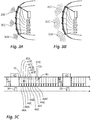
- Figures 3A to 3C shows a situation that can arise, for example, when parking the vehicle. In this situation it is necessary to recognize the environment as precisely as possible in order to avoid collisions.
- FIG. 3A shows, it is provided for this that three of the six sensor units, namely in the present case the sensor units 20A, 20C and 20E, are to transmit a signal.
- a command to this effect is transmitted to the relevant sensor units in the CRM phase 40.
- these sensor units 20A, 20C, 20E can also be informed in this phase 40 how the signal to be transmitted is to be individualized, for example by defining a particular transmission frequency so that the echo signals can later be distinguished.
- the sensor units 20A-20F always individualize the signal when it is transmitted using a parameter dependent on their bus identifier, for example by encoding the bus identifier in the signal to be transmitted.
- the control device 14 transmits to the sensor units 20B, 20D the bus identifier of one of the two virtual slaves described above, in this case the "7" and the "8" as an example.
- the commands in this regard tell the two sensor units 20B, 20D that they each have two time slots available for data transmission to the control device 14 in the subsequent PDCM phase, namely the fixed one specified their bus identifiers ("2" or "4") assigned and one variably assigned ("7” or "8").
- the control device After completion of the CRM phase 40, the control device increases the bus voltage in the manner already described to a value beyond the highest voltage usual for data transmission and thus initiates the power phase 43.
- the sensor units hereby charge their respective capacitors 23 and the selected sensor units 20A, 20C, 20E then each transmit their ultrasonic signal 30A, 30C, 30E.
- the control device 14 Using the first synchronization signal 45, the control device 14 initiates the data transmission from the sensor units 20A to 20E to the control device 14. First of all, all six sensor units 20A-20F send the recorded data of a first echo signal to the control device in their permanently assigned time slot 47A-47F. As soon as this has happened, the two sensor units 20B, 20D send the recorded data of the second echo signal which were recorded by them in the time slots 47G, 47H additionally assigned to them for this measuring cycle.
- the time slots are not sufficient to completely transmit the recorded data of an echo signal to the control device, so that the control device sends a second synchronization signal 45, which again gives each sensor unit 20A-20F the opportunity to convert the remaining data into their respective time slot 47A-47F.
- the sensor units 20B, 20D also transmit in the time slot 47G, 47H additionally assigned to them for this measurement cycle.
- the second example of the Figures 4A to 4C represents a driving situation that can arise in city traffic.
- the sensor units 20D and 20F that are to emit ultrasonic signals.
- the sensor unit 20A should also emit an ultrasonic signal by means of which the oncoming traffic can be observed.
- commands are therefore issued from the control device 14 to these sensor units 20A, 20D, 20F that they have to send out signals, possibly supplemented by parameters for the signal to be sent out, so that they remain distinguishable from one another.
- a command is sent to the sensor 20E, by means of which the time slot 47G of one of the two virtual slaves is assigned to this sensor, in this case the virtual slave with the bus identifier "7".
- the virtual slave with the bus identifier "8" and its time slot 47H are not assigned to any of the sensor units in this second example.
- the selected sensor units 20B, 20D, 20F now send their respective ultrasonic signals 32B, 32D, 32F in the power phase 43, as in FIG Figure 4A is made clear. These ultrasonic signals are in turn reflected on reflective surfaces and reach the sensor units as echo signals 33B, 33D, 33F.
- the sensor unit 20E then uses the time slot 47G, which is assigned to the bus identifier “7”, in order to transmit its larger amount of data to the control device 14 compared to the other sensor units.
- the specialty in this second example is that the time slot 47H, which is assigned to the bus identifier "8" and which was not assigned to any of the sensor units 20A to 20F, does not have to be waited for. After receiving the data of the time slot 47F with the bus identifier "7", the control unit 14 immediately sends the second synchronization signal 45, since it knows that it has assigned the bus identifier "8" and therefore no more data can be expected.
- the signal emitted by said sensor units 20B, 20F is reflected, it returns to the sensor units as echo signal 35B, 35F, sensor units 20A to 20C detecting echo signal 36B and sensor units 20D to 20F detecting echo signal 36F.
- the data transmission by the sensor units 20A to 20F is initiated. All sensor units 20A-20F transmit the recorded data in their respective time slot 47A-47F.
- the control device 14 sends the second synchronization signal 45 in order to receive the remaining data in the second time slots 47A-47F. The control device 14 then switches back to the CRM mode and thus initiates the next measurement cycle.
- the total of eight time slots 47A to 47H do not result in an extension of the measurement cycle in this third example, unless this is required by the amount of data.
- the third example also shows that the measuring cycle then if there is no increased amount of data, it is not extended compared to a conception of the sensor arrangement completely without virtual slaves
- the main advantage of the shortening of the measuring cycles according to the second and third example is a higher measuring frequency. While a lower measurement frequency can be tolerated in the parking situation of the first example due to the low speeds usually given here, in the city traffic situation of example 2 as well as the highway situation of example 3 and due to the higher speeds prevailing here, it is very advantageous that measurement cycles are shortened and the measuring frequency is increased
Description
Die Erfindung betrifft Verfahren zum Betrieb einer Sensoranordnung auf Basis eines DSI-Protokolls in einem Kraftfahrzeug sowie eine Sensoranordnung in einem Kraftfahrzeug, die mittels eines erfindungsgemäßen Verfahrens betrieben wird.The invention relates to a method for operating a sensor arrangement based on a DSI protocol in a motor vehicle and to a sensor arrangement in a motor vehicle that is operated by means of a method according to the invention.
Das DSI-Protokoll (
Die Spezifikation des DSI-Protokolls sieht dabei vor, dass eine solche Sensoranordnung, umfassend mindestens eine Zentralinstanz und mindestens eine Satelliteninstanz, in einer von zwei Betriebsklassen betrieben werden kann, einerseits der "Signal Function Class", andererseits der "Power Function Class".The specification of the DSI protocol provides that such a sensor arrangement, comprising at least one central instance and at least one satellite instance, can be operated in one of two operating classes, on the one hand the "Signal Function Class" and on the other hand the "Power Function Class".
Das Protokoll sieht weiterhin grundsätzlich drei unterschiedliche Typen der Nutzung des Busses zwischen der Zentralinstanz und der Satelliteninstanz vor:
Im CRM-Modus (Command and Response Modus) findet eine bidirektionale Kommunikation zwischen der Zentralinstanz und der Satelliteninstanz statt. Die Zentralinstanz sendet ein Kommando (Command), auf das die Satelliteninstanz antwortet (Response). Dies wird beispielsweise verwendet, um die Satelliteninstanzen zu konfigurieren oder um bestimmte Werte gezielt von einer Satelliteninstanz abzufragen.The protocol also provides for three different types of use of the bus between the central instance and the satellite instance:
In the CRM mode (Command and Response mode) there is bidirectional communication between the central instance and the satellite instance. The central instance sends a command to which the satellite instance responds (response). This is used, for example, to configure the satellite instances or to request specific values from a satellite instance.
Im PDCM-Modus (Periodic Data Collection Mode) übertragen die Satelliteninstanzen vergleichsweise große Datenmengen innerhalb eines vorgegebenen Zeitschlitzes an die Zentralinstanz, wobei die Sendetätigkeit der Zentralinstanz sich darauf beschränkt, durch ein Synchronisierungssignal (Broadcast Read Command) den Satelliteninstanzen einen Bezugspunkt zur Bestimmung dieses Zeitschlitzes zur Verfügung zu stellen. Die Satelliteninstanzen sind bereits zuvor mit Informationen zu ihrem jeweiligen Zeitschlitz ausgestattet worden, so dass sie in Reaktion auf das Synchronisierungssignal ihr jeweiliges Sendezeitintervall bestimmen können und auf Basis dessen ihre Sensordaten an die Zentralinstanz senden können.In PDCM mode (Periodic Data Collection Mode), the satellite entities transmit comparatively large amounts of data to the central entity within a specified time slot, the transmission activity of the central entity being limited to a Synchronization signal (Broadcast Read Command) to provide the satellite entities with a reference point for determining this time slot. The satellite entities have already been provided with information on their respective time slot beforehand, so that they can determine their respective transmission time interval in response to the synchronization signal and, on the basis of this, can send their sensor data to the central entity.
In der Power-Phase findet die Übertragung von vergleichsweise großen Mengen elektrischer Energie statt, um Satelliteninstanzen mit hohem Energiebedarf mit dieser zu versorgen.In the power phase, comparatively large amounts of electrical energy are transmitted in order to supply satellite entities with high energy requirements.
Die eingangs genannte "Signal Function Class" gemäß der oben genannten Spezifikation dient primär der Anbindung von Sensor-Satelliteninstanzen mit geringem Energiebedarf und vergleichsweise hohem Datenaufkommen, welches von der Satelliteninstanz zur Zentralinstanz zu senden ist. Nach Inbetriebnahme einer Sensoranordnung der "Signal Function Class" findet zunächst eine Phase der Kommunikation im CRM-Modus zwischen der Zentralinstanz und der Satelliteninstanz statt, im Rahmen derer die Satelliteninstanz üblicherweise konfiguriert wird, beispielsweise in Hinblick auf die Parameter des oben genannten PDCM-Zeitschlitzes dieser Satelliteninstanz. Ist diese Phase abgeschlossen, so geht die Sensoranordnung in den PCDM-Modus über, in dem immer in Reaktion auf das Synchronisierungssignal der Zentralinstanz die Sensor-Satelliteninstanz oder die Sensor-Satelliteninstanzen die erfassten Daten im jeweils zugeordneten Zeitschlitz an die Zentralinstanz senden. Diese Phase im PDCM-Modus wird üblicherweise nicht mehr verlassen, bis der Betrieb der Sensoranordnung unterbrochen wird. Eine Power-Phase ist gemäß "Signal Function Class" nicht vorgesehen und aufgrund des genannten geringen Energiebedarfs auch nicht erforderlich.The "signal function class" mentioned at the beginning according to the above specification is primarily used to connect sensor satellite entities with a low energy requirement and a comparatively high volume of data that is to be sent from the satellite entity to the central entity. After commissioning a sensor arrangement of the "signal function class", a phase of communication in CRM mode takes place between the central entity and the satellite entity, during which the satellite entity is usually configured, for example with regard to the parameters of the above-mentioned PDCM timeslot Satellite instance. When this phase is completed, the sensor arrangement switches to PCDM mode, in which the sensor satellite entity or the sensor satellite entities always send the recorded data in the assigned time slot to the central entity in response to the synchronization signal from the central entity. This phase in the PDCM mode is usually not left until the operation of the sensor arrangement is interrupted. A power phase is not provided in accordance with the "Signal Function Class" and is also not required due to the aforementioned low energy requirement.
Die genannte "Power Function Class" dient primär der Anbindung von Aktor-Satelliteninstanzen mit vergleichsweise hohem Energiebedarf und vergleichsweise geringem Datenaufkommen, welches von der Zentralinstanz zur Satelliteninstanz zu senden ist. Im Betrieb einer Sensoranordnung der "Power Function Class" finden im Wechsel Phasen der Kommunikation zwischen der Zentralinstanz und der Satelliteninstanz im CRM-Modus sowie Power-Phasen statt. Dabei überwiegen zeitlich üblicherweise die Power-Phasen deutlich. Durch die Speisung der Satelliteninstanzen in diesen Phasen mit vergleichsweise viel Energie bei verglichen mit dem CRM-Modus höherer Spannung können insbesondere Aktoren betrieben werden, wobei dies üblicherweise auf Basis von zuvor in der CRM-Phase von der Zentralinstanz an die Satelliteninstanz übertragenen Steuerbefehlen erfolgt. Der PDCM-Modus findet gemäß "Power Function Class" keine Anwendung, da er bei den genannten Aktoren aufgrund geringen Datenaufkommens auch nicht erforderlich ist.The so-called "Power Function Class" primarily serves to connect actuator satellite entities with a comparatively high energy requirement and a comparatively low volume of data to be sent from the central entity to the satellite entity. In operation of a sensor arrangement of the "power function class", phases of communication between the central instance and the satellite instance in CRM mode and power phases alternate. In terms of time, the power phases usually clearly predominate. By supplying the satellite entities in these phases with a comparatively large amount of energy at a higher voltage than in the CRM mode, actuators in particular can be operated, this usually being based on control commands previously transmitted from the central entity to the satellite entity in the CRM phase. According to the "Power Function Class", the PDCM mode is not used because it is not necessary for the actuators mentioned due to the low volume of data.
Die DSI3-Spezifikationen legen also mit der "Signal Function Class" und der "Power Function Class" zwei Möglichkeiten des Betriebs der Sensoranordnung fest, die einerseits für den Betrieb von Sensoren mit geringem Energiebedarf und hohen Datenaufkommen und andererseits für den Betrieb von Aktoren mit hohem Energiebedarf und geringem Datenaufkommen gut geeignet sind. Ein gemischter Betrieb von "Signal Function Class"-Satelliteninstanzen und "Power Function Class"-Satelliteninstanzen ist gemäß der genannten Spezifikation möglich, wenn der Bus als "Power Function Class"-Bus betrieben wird und die "Signal Function Class"-Satelliteninstanz derart ausgelegt sind, dass sie die erhöhte Spannung in der genannten Power-Phase schadlos überstehen. Es ist jedoch schwierig, auf Basis dieser beiden Funktionsklassen den Betrieb von aktiven Sensoreinheiten zu ermöglichen, zu denen insbesondere Satelliteninstanzen mit Sensoren zählen, die auf Basis eines aktiv von der Satelliteninstanz erzeugten Signals bzw. dessen Echo die Umgebung eines Fahrzeugs sensieren.With the "Signal Function Class" and the "Power Function Class", the DSI3 specifications define two options for operating the sensor arrangement, on the one hand for the operation of sensors with low energy requirements and high data volumes and on the other hand for the operation of actuators with high Energy requirements and low data volume are well suited. Mixed operation of "signal function class" satellite entities and "power function class" satellite entities is possible according to the specification mentioned if the bus is operated as a "power function class" bus and the "signal function class" satellite entity is designed in this way are that they withstand the increased voltage in the aforementioned power phase without damage. However, it is difficult to enable the operation of active sensor units on the basis of these two functional classes, which include in particular satellite entities with sensors that sense the surroundings of a vehicle on the basis of a signal actively generated by the satellite entity or its echo.
Ein weiterer Nachteil des DSI3-Standards gemäß der genannten Spezifikation ergibt sich im Falle von Sensoranordnungen, deren Sensoren fallweise unterschiedliche Datenmengen erfassen und an die Zentralinstanz weitergeben müssen. Zwar erlaubt es der DSI3-Standard, die zur Datenübermittlung an die Zentralinstanz verfügbare Datenmenge im PDCM-Modus flexibel festzulegen. Um dies jedoch dynamisch im Betrieb zu ermöglichen, muss die Zentralinstanz zunächst im CRM-Modus die Zeitschlitze für die Satelliteninstanzen neu festsetzen. Die hierfür erforderliche Datenmenge ist vergleichsweise groß und muss auf mehrere Befehle der Zentralinstanz verteilt werden, so dass die übertragbare Datenmenge von den Satelliteninstanzen zur Zentralinstanz entsprechend sinkt.A further disadvantage of the DSI3 standard in accordance with the specified specification arises in the case of sensor arrangements, the sensors of which, on a case-by-case basis, record different amounts of data and pass them on to the central instance. The DSI3 standard allows the amount of data available for data transmission to the central instance to be flexibly defined in PDCM mode. However, in order to enable this dynamically during operation, the central entity must first set the time slots for the satellite entities anew in CRM mode. The amount of data required for this is comparatively large and has to be distributed over several commands from the central instance, so that the amount of data that can be transmitted from the satellite instances to the central instance decreases accordingly.
Aus der
Aufgabe der Erfindung ist es, ein Verfahren zum Betrieb einer Sensoranordnung in einem Fahrzeug auf Basis eines DSI-Protokolls zur Verfügung zu stellen, welches die Nachteile der unzureichenden Unterstützung aktiver Sensoren und variabler Datenmengen verringert.The object of the invention is to provide a method for operating a sensor arrangement in a vehicle on the basis of a DSI protocol, which method reduces the disadvantages of insufficient support for active sensors and variable amounts of data.
Erfindungsgemäß erfolgt dies gemäß einem ersten Aspekt der Erfindung mittels des folgenden Verfahrens, welches in einer Sensoranordnung Anwendung findet, die über mindestens eine Verarbeitungseinheit (als Master / Zentraleinheit) und mindestens eine aktive Sensoreinheit (als Slave / Satelliteneinheit) verfügt, die über einen Bus aus zwei Leitungen miteinander verbunden sind. Die aktive Sensoreinheit kann insbesondere als Ultraschall-Sensoreinheit mit Sender und Empfänger ausgebildet sein.According to the invention, this is done according to a first aspect of the invention by means of the following method, which is used in a sensor arrangement that has at least one Processing unit (as master / central unit) and at least one active sensor unit (as slave / satellite unit), which are connected to one another via a bus consisting of two lines. The active sensor unit can in particular be designed as an ultrasonic sensor unit with a transmitter and receiver.
Gemäß dem Verfahren erfolgt die Kommunikation zwischen der Verarbeitungseinheit und den aktiven Sensoreinheiten oder der mindestens einen aktiven Sensoreinheit mit einer sich wiederholenden Sequenz dreier Phasen, wobei es auf die konkrete Reihenfolge nicht ankommt.According to the method, the communication between the processing unit and the active sensor units or the at least one active sensor unit takes place with a repeating sequence of three phases, the specific sequence not being important.
In einer ersten Phase kommunizieren die Verarbeitungseinheit und die aktive Sensoreinheit bidirektional im CRM-Modus. In dieser Phase werden also einfach oder wiederholt Befehle von der Verarbeitungseinheit an eine oder mehrere aktive Sensoreinheiten gesendet, wobei diese Befehle insbesondere dem Zweck dienen, die aktiven Sensoreinheiten mit Parametern eines anstehenden Messzyklus zu versorgen. Hierzu gehört insbesondere der Befehl zum Aussenden eines Signals (Tx-Signal), dessen Echo (Rx-Signal) anschließend sensiert wird.In a first phase, the processing unit and the active sensor unit communicate bidirectionally in CRM mode. In this phase, commands are sent from the processing unit to one or more active sensor units once or repeatedly, these commands serving in particular the purpose of supplying the active sensor units with parameters of an upcoming measurement cycle. This includes in particular the command to transmit a signal (Tx signal), the echo of which (Rx signal) is then sensed.
In einer zweiten Phase erfolgt die Energieversorgung der aktiven Sensoreinheiten. In dieser Phase werden keine Daten übermittelt, sondern es wird bei erhöhter Busspannung jene Energie zu den aktiven Sensoreinheiten übertragen, die diese für den Betrieb und insbesondere für das Aussenden des Signals, dessen Echo anschließend sensiert werden soll, benötigen. Diese Energie wird vorzugsweise teilweise in den aktiven Sensoreinheiten gepuffert, so dass bis zur folgenden Energieversorgungsphase ausreichend Energie zur Verfügung steht.In a second phase, the active sensor units are supplied with energy. In this phase, no data is transmitted, but when the bus voltage is increased, the energy that is transmitted to the active sensor units is that they need for operation and, in particular, for the transmission of the signal whose echo is then to be sensed. This energy is preferably partially buffered in the active sensor units, so that sufficient energy is available until the next energy supply phase.
Im Falle einer Sensoranordnung mit Ultraschallsensoren oder anderweitigen aktiven Sensoren, die nur phasenweise hohe Energie benötigen, ist es von Vorteil, wenn diese Phasen hohen Energiebedarfs sich zumindest teilweise mit der Phase der Energieversorgung überlappen. Im Falle von Ultraschall-Sensoreinheiten oder anderen aktiven Sensoren mit Sender und Empfänger ist es insbesondere von Vorteil, wenn das Aussenden des Ultraschallimpulses oder eines elektromagnetischen Impulses während der Phase der Energieversorgung stattfindet, so dass die hierfür erforderliche Energie nicht zuvor in der aktiven Sensoreinheit gepuffert werden muss.In the case of a sensor arrangement with ultrasonic sensors or other active sensors that only require high energy in phases, it is advantageous if these phases of high energy demand at least partially overlap with the phase of the energy supply. In the case of ultrasonic sensor units or other active sensors with transmitter and receiver, it is particularly advantageous if the ultrasonic pulse or an electromagnetic pulse is emitted during the energy supply phase, so that the energy required for this is not previously buffered in the active sensor unit got to.
In einer dritten Phase sendet die aktive Sensoreinheit im PDCM-Modus die Sensordaten an die Verarbeitungseinheit. Hierbei handelt es sich um eine unidirektionale Datenübertragung. Die Verarbeitungseinheit sendet lediglich ein Synchronisierungssignal, das als Referenz dient, damit die aktive Sensoreinheit bzw. die aktiven Sensoreinheiten anschließend in jeweils zuvor festgelegten Zeitschlitzen ihre jeweiligen Daten senden. Dabei kann in dieser Phase je nach Datenmenge auch ein wiederholtes Senden des Synchronisierungssignals durch die Verarbeitungseinheit vorgesehen sein, so dass die aktiven Sensoreinheiten die jeweiligen Daten verteilt auf mehrere Zeitschlitze senden.In a third phase, the active sensor unit sends the sensor data to the processing unit in PDCM mode. This is a unidirectional data transfer. The processing unit only sends a synchronization signal, which serves as a reference, so that the active sensor unit or the active sensor units then send their respective data in respectively previously defined time slots. In this phase, depending on the amount of data, a repeated sending of the synchronization signal by the processing unit can be provided so that the active sensor units send the respective data distributed over several time slots.
Wie eingangs bereits erwähnt, handelt es sich bei diesem Verfahren gemäß dem ersten Aspekt der Erfindung ebenso wie auch beim Verfahren gemäß dem im Weiteren noch erläuterten zweiten Aspekt der Erfindung um ein Verfahren auf Basis des DSI-Standards. Dies bedeutet, dass die genannten Datenübertragungs-Phasen im CRM-Modus und im PDCM-Modus sowie die Energieübertragungs-Phase vorzugsweise entsprechend der genannten DSI-Spezifikation die folgenden Parameter vollständig oder teilweise erfüllen.As already mentioned at the beginning, this method according to the first aspect of the invention, as well as the method according to the second aspect of the invention explained below, is a method based on the DSI standard. This means that the data transmission phases mentioned in CRM mode and PDCM mode as well as the energy transmission phase preferably meet the following parameters in full or in part in accordance with the DSI specification mentioned.
Als PDCM-Modus wird demnach ein Datenübermittlungs-Modus angesehen, in dem eine im Wesentlichen unidirektionale Datenübermittlung von der aktiven Sensoreinheit oder den aktiven Sensoreinheiten zur Verarbeitungseinheit stattfindet. Die Sendetätigkeit der aktiven Sensoreinheit richtet sich dabei nach einer zuvor übermittelten Zuordnung von Zeitschlitzen sowie einem Synchronisierungssignal der Verarbeitungseinheit von einem bis drei Bit Länge als Zeitreferenz. In der PDCM-Phase erfolgt der Ablauf, beginnend mit dem Synchronisierungssignal der Verarbeitungseinheit und anschließend mit der Datenübermittlung von den aktiven Sensoreinheiten an die Verarbeitungseinheit üblicherweise mehrfach hintereinander.The PDCM mode is accordingly regarded as a data transmission mode in which an essentially unidirectional data transmission takes place from the active sensor unit or the active sensor units to the processing unit. The transmission activity of the active sensor unit is based on a previously transmitted assignment of time slots and a synchronization signal from the processing unit with a length of one to three bits as a time reference. In the PDCM phase, the sequence takes place, starting with the synchronization signal of the processing unit and then with the data transmission from the active sensor units to the processing unit, usually several times in succession.
Als CRM-Modus wird ein Datenübermittlungs-Modus angesehen, in dem die Verarbeitungseinheit einen meist anhand der Buskennung für eine aktive Sensoreinheit adressierten Befehl oder globalen Befehl auf den Bus sendet und die ggf. hiermit adressierte aktive Sensoreinheit mit einer vom Inhalt des Befehls abhängigen Antwort antwortet. Dabei sind vorzugsweise entsprechend der DSI-Spezifikation sowohl der Befehl als auch die Antwort jeweils 32 Bit lang.The CRM mode is a data transmission mode in which the processing unit sends a command or global command, usually addressed using the bus identifier for an active sensor unit, to the bus, and the active sensor unit addressed hereby responds with a response that depends on the content of the command . In accordance with the DSI specification, both the command and the response are preferably 32 bits long.
Die Datenübermittlung von der Verarbeitungseinheit auf die aktive Sensoreinheit im CRM-Modus und im PDCM-Modus erfolgt gemäß der DSI-Spezifikation durch Spannungsmodulation der Busspannung. Hierbei werden zur Datenübermittlung zwei Spannungen VLow von 2 V (+/- 0,25 V) und VHigh von 4 V (+/- 0,5 V) sowie eine Manchesterkodierung benutzt. Es ist vorzugsweise eine Übertragungsgeschwindigkeit von 8 µsec/Bit vorgesehen.The data transfer from the processing unit to the active sensor unit in CRM mode and in PDCM mode takes place in accordance with the DSI specification by voltage modulation of the bus voltage. Two voltages V low of 2 V (+/- 0.25 V) and V high of 4 V (+/- 0.5 V) as well as a Manchester coding are used for data transmission. A transmission speed of 8 microseconds / bit is preferably provided.
In der Richtung von den aktiven Sensoreinheiten zur Verarbeitungseinheit im CRM-Modus und im PDCM-Modus erfolgt die Datenübermittlung gemäß der DSI-Spezifikation durch Stromstärkenmodulation, wobei die Stromstärke zwischen drei Niveaus wechselt, um statt eines Bits mit zwei möglichen Zuständen drei mögliche Zustände zu ermöglichen. Diese Informationseinheit, die drei Werte annehmen kann, wird als "Chip" bezeichnet. Es ist vorzugsweise eine Übertragungsgeschwindigkeit zwischen 2,7 µsec/Chip und 10 µsec/Chip vorgesehen.In the direction from the active sensor units to the processing unit in CRM mode and in PDCM mode, data is transmitted in accordance with the DSI specification by current intensity modulation, with the current intensity changing between three levels in order to enable three possible states instead of one bit with two possible states . These Information unit that can take on three values is called a "chip". A transmission speed between 2.7 μsec / chip and 10 μsec / chip is preferably provided.
In der Energieübertragungsphase findet eine oberhalb von VHigh liegende Spannung Verwendung, die in der Spezifikation mit VIdle bezeichnet ist und die gemäß Spezifikation maximal 25 V betragen darf. Vorliegend findet die Energieübertragung vorzugweise mindestens mit einer Spannung von 6 V statt, damit diese von den aktiven Sensoreinheiten von VHigh zu unterscheiden ist.In the energy transfer phase, a voltage above V High is used, which is referred to in the specification as V Idle and which, according to the specification, may not exceed 25 V. In the present case, the energy transfer preferably takes place at a voltage of at least 6 V, so that it can be distinguished from the active sensor units of V High .
Der oben beschriebene erste Aspekt der Erfindung sieht vor, dass abweichend vom DSI-Standard und insbesondere zur Anbindung aktiver Sensoren die Kommunikation zwischen der Verarbeitungseinheit und den aktiven Sensoreinheiten sowohl eine Phase schneller Datenübermittlung (PDCM-Phase) als auch eine Phase der Energieversorgung (Power-Phase) beinhaltet. Es werden hierdurch die beiden Besonderheiten der eingangs genannten "Signal Function Class" und der "Power Function Class" in einem gemeinsamen Betriebsmodus vereinigt.The first aspect of the invention described above provides that, deviating from the DSI standard and in particular to connect active sensors, the communication between the processing unit and the active sensor units includes both a phase of fast data transmission (PDCM phase) and a phase of the energy supply (power Phase). The two special features of the "Signal Function Class" and the "Power Function Class" mentioned at the beginning are combined in a common operating mode.
Hierdurch entfällt die anderenfalls erforderliche Anbindung des aktiven Sensors an eine separate Stromversorgung und es kann eine sehr einfache und kostengünstige Verkabelung verwendet werden.This eliminates the otherwise necessary connection of the active sensor to a separate power supply and very simple and inexpensive cabling can be used.
Trotz der Änderung der Bus-Kommunikation entgegen dem DSI3-Standard bleibt die Kompatibilität vorhanden. Bei Wahl der Betriebsparametern gemäß der Spezifikation ist auch ein gemischter Betrieb mit Geräten möglich, die nur zu Kommunikation gemäß den DSI3-Spezifikationen ("Signal Power Class" oder "Signal Function Class") ausgebildet sind, da diese die Ihnen nicht zugänglichen Buskommunikationsphasen ignorieren.Despite the change in bus communication contrary to the DSI3 standard, the compatibility remains. If the operating parameters are selected in accordance with the specification, mixed operation with devices that are only designed for communication in accordance with the DSI3 specifications ("Signal Power Class" or "Signal Function Class") is possible, as these ignore the bus communication phases that are not accessible to you.
Das Betriebsverfahrens ist für den Betrieb von aktiven Sensoreinheiten vorgesehen. Unter einer aktiven Sensoreinheit in diesem Sinne wird eine Sensoreinheit verstanden, die einen Sender zum Aussenden eines Signals und einen Empfänger zum Empfangen einer Reflexion dieses Signals, also eines Echo-Signals, umfasst. Insbesondere sind die hier beschriebenen Betriebsverfahren für eine Sensoranordnung mit aktiven Ultraschall-Sensoreinheiten vorgesehen. Diese weisen sowohl einen recht hohen Leistungsbedarf als auch ein hohes Aufkommen an Daten auf.The operating method is intended for the operation of active sensor units. An active sensor unit in this sense is understood to mean a sensor unit which comprises a transmitter for transmitting a signal and a receiver for receiving a reflection of this signal, that is to say an echo signal. In particular, the operating methods described here are intended for a sensor arrangement with active ultrasonic sensor units. These have both a very high power requirement and a high volume of data.
Das Aussenden des Signals durch eine solche aktive Sensoreinheit erfolgt vorzugsweise während der Power-Phase, in der die Sensoreinheit von der Verarbeitungseinheit mit vergleichsweise hoher Leistung versorgt wird, so dass der Betrieb des Senders unmittelbar aus der über den Bus zugeführten Leistung gespeist werden kann. Dennoch weisen die Sensoreinheiten vorzugsweise einen Energiespeicher, insbesondere in Form eines Kondensators, auf, mittels dessen die in der Power-Phase übertragene Energie bis zur nächsten Power-Phase in der Sensoreinheit gepuffert werden kann.The transmission of the signal by such an active sensor unit takes place preferably during the power phase, in which the sensor unit is supplied with comparatively high power by the processing unit, so that the transmitter can be operated directly from the bus supplied power can be fed. Nevertheless, the sensor units preferably have an energy store, in particular in the form of a capacitor, by means of which the energy transmitted in the power phase can be buffered in the sensor unit until the next power phase.
Ob die Sensoreinheit ein Signal und ggf. weitergehende Parameter zu dem auszusendenden Signal aussenden soll, wird der Sensoreinheit vorzugsweise in der genannten CRM-Phase übermittelt.Whether the sensor unit should send out a signal and, if necessary, further parameters for the signal to be sent out, is preferably transmitted to the sensor unit in the CRM phase mentioned.
Gemäß dem zweiten Aspekt der Erfindung wird ein Verfahren vorgeschlagen, welches in der Praxis vorzugsweise gemeinsam mit dem beschriebenen Verfahren gemäß dem ersten Aspekt der Erfindung realisiert ist, grundsätzlich jedoch auch unabhängig hiervon realisiert sein kann. Das Verfahren findet in einer Sensoranordnung Anwendung, die über mindestens eine Verarbeitungseinheit (Master) und mindestens eine aktive Sensoreinheit (Slave) verfügt, die über einen Bus aus zwei Leitungen miteinander verbunden sind. Besonders zweckmäßig ist dieses Verfahren jedoch bei einem Bus mit einer Mehrzahl von aktiven Sensoreinheiten.According to the second aspect of the invention, a method is proposed which, in practice, is preferably implemented together with the described method according to the first aspect of the invention, but can in principle also be implemented independently thereof. The method is used in a sensor arrangement which has at least one processing unit (master) and at least one active sensor unit (slave), which are connected to one another via a bus consisting of two lines. However, this method is particularly useful in the case of a bus with a plurality of active sensor units.
Gemäß diesem Verfahren erfolgt die Kommunikation zwischen der Verarbeitungseinheit und der mindestens einen aktiven Sensoreinheit mit einer sich üblicherweise wiederholenden Sequenz mindestens der beiden folgenden Teilphasen.According to this method, the communication between the processing unit and the at least one active sensor unit takes place with a usually repeating sequence of at least the two following partial phases.
In einer ersten Phase kommunizieren die Verarbeitungseinheit und die aktive Sensoreinheit bidirektional im CRM-Modus. In dieser Phase werden einfach oder wiederholt Befehle von der Verarbeitungseinheit an eine oder mehrere aktive Sensoreinheiten gesendet, wobei mittels eines Befehles der Verarbeitungseinheit der aktiven Sensoreinheit eine Freigabe erteilt wird, durch die diese aktive Sensoreinheit zusätzlich zu einem der aktiven Sensoreinheit fest zugeordneten Zeitschlitz einen zusätzlichen ergänzenden Zeitschlitz zugeordnet bekommt. Bei einer Sensoranordnung mit mindestens zwei aktiven Sensoreinheiten wird diese Freigabe einer der beiden aktiven Sensoreinheiten zugeordnet.In a first phase, the processing unit and the active sensor unit communicate bidirectionally in CRM mode. In this phase, commands are sent simply or repeatedly from the processing unit to one or more active sensor units, with a command from the processing unit of the active sensor unit being given a release through which this active sensor unit adds an additional time slot in addition to a time slot permanently assigned to the active sensor unit Gets assigned time slot. In the case of a sensor arrangement with at least two active sensor units, this release is assigned to one of the two active sensor units.
In einer anschließenden weiteren Phase im PDCM-Modus senden die aktiven Sensoreinheiten jeweils Sensordaten im Wesentlichen unidirektional an die Verarbeitungseinheit. Hierbei sendet jene aktive Sensoreinheit, der zuvor in der CRM-Phase die Freigabe für einen ergänzenden Zeitschlitz erteilt worden ist, sowohl in dem ihr fest zugeordneten Zeitschlitz als auch in dem ihr zugeordneten ergänzenden Zeitschlitz Daten an die Verarbeitungseinheit.In a subsequent further phase in PDCM mode, the active sensor units each send sensor data essentially unidirectionally to the processing unit. In this case, that active sensor unit, which was previously given the approval for an additional time slot in the CRM phase, sends data to the processing unit both in the time slot assigned to it and in the additional time slot assigned to it.
Die Zeitschlitze, die für die Übermittlung von Daten an die Verarbeitungseinheit definiert sind und die charakteristisch für die Datenübermittlung im PDCM-Modus sind, sind bereits zuvor durch die Verarbeitungseinheit festgelegt worden und vorzugsweise im Rahmen einer initialen Phase der Datenübermittlung im CRM-Modus an die aktive Sensoreinheit übermittelt worden. Hierbei definiert die Verarbeitungseinheit mehr Zeitschlitze als aktive Sensoreinheiten am Bus vorgesehen sind, so dass zusätzlich zu den Zeitschlitzen, die fest einer aktiven Sensoreinheit zugeordnet sind, mindestens ein Zeitschlitz verbleibt, der variabel zugeordnet werden kann, also in verschiedenen Messzyklen verschiedenen aktiven Sensoreinheit zuordenbar ist. Dieser mindestens eine variabel zuordenbare Zeitschlitz kann als Zeitschlitz einer virtuellen, nicht real existenten, Sensoreinheit verstanden werden (virtueller Slave).The time slots which are defined for the transmission of data to the processing unit and which are characteristic of the data transmission in PDCM mode have already been defined beforehand by the processing unit and preferably during an initial phase of data transmission in CRM mode to the active one Sensor unit has been transmitted. The processing unit defines more time slots than there are active sensor units on the bus, so that in addition to the time slots that are permanently assigned to an active sensor unit, at least one time slot remains that can be variably assigned, i.e. can be assigned to different active sensor units in different measuring cycles. This at least one variably assignable time slot can be understood as a time slot of a virtual, non-real sensor unit (virtual slave).
Wenn im Zuge der CRM-Phase die Freigabe des zusätzlichen Zeitschlitzes erfolgt, wird dieser mindestens eine variabel zuordenbare Zeitschlitz einer der aktiven Sensoreinheiten zugeordnet, insbesondere durch Übermittlung einer Identifikationskennung dieses Zeitschlitzes bzw. der virtuellen Sensoreinheit, der dieser Zeitschlitz zugeordnet ist. Die betreffende aktive Sensoreinheit kann auf Basis dessen anhand der schon zuvor vorliegenden Daten über die Zeitschlitze ermitteln, in welchem zusätzlichen Zeitschlitz sie nun zum Senden berechtigt ist.If the additional time slot is released in the course of the CRM phase, it is assigned at least one variably assignable time slot to one of the active sensor units, in particular by transmitting an identification code for this time slot or the virtual sensor unit to which this time slot is assigned. On the basis of this, the relevant active sensor unit can use the data about the time slots that were already available beforehand to determine in which additional time slot it is now authorized to transmit.
Im einfachsten Falle definiert die Verarbeitungseinheit nur eine virtuelle Sensoreinheit mitsamt einem Zeitschlitz, der dann variabel einer der realen aktiven Sensoreinheit zugeordnet werden kann. Es ist jedoch auch denkbar, dass mehrere virtuelle Sensoreinheiten definiert werden, die dann jeweils einen variabel zuordenbaren Zeitschlitz aufweisen, so dass mehreren realen aktiven Sensoreinheiten für die gleiche PDCM-Phase jeweils ein zusätzlicher Zeitschlitz zugeordnet werden kann oder einer realen aktiven Sensoreinheit für eine PDCM-Phase mehrere zusätzliche Zeitschlitze zugeordnet werden können. Die Zeitschlitze müssen gemäß Spezifikation keine einheitliche Länge haben. Es ist also beispielsweise auch denkbar, die Zeitschlitze der realen aktiven Sensoreinheit und der virtuellen Slaves unterschiedlich lang auszugestalten, wenn die spezifische Gestaltung der aktiven Sensoreinheit regelmäßig dazu führt, dass entweder sehr wenig Daten oder sehr viele Daten anfallen.In the simplest case, the processing unit defines only a virtual sensor unit including a time slot, which can then be variably assigned to one of the real active sensor units. However, it is also conceivable that several virtual sensor units are defined, which then each have a variably assignable time slot, so that several real active sensor units for the same PDCM phase can each be assigned an additional time slot or a real active sensor unit for a PDCM Phase several additional time slots can be assigned. According to the specification, the time slots do not have to have a uniform length. It is therefore also conceivable, for example, to design the time slots of the real active sensor unit and the virtual slaves of different lengths if the specific design of the active sensor unit regularly results in either very little data or very much data being generated.
Eine alternative Möglichkeit zur erfindungsgemäßen Definition zusätzlicher und variabel zuordenbarer Zeitschlitze und zur fallweisen Freigabe derer läge darin, stattdessen dynamisch die Größe der Zeitschlitze zu verändern. Dies jedoch würde dazu führen, dass eine erheblich größere Datenmenge von der Verarbeitungseinheit auf die aktive Sensoreinheit übertragen werden müsste, um alle aktiven Sensoreinheiten wiederholt über die geänderte Anordnung der Zeitschlitze zu informieren.An alternative possibility for the definition of additional and variably assignable time slots according to the invention and for enabling them on a case-by-case basis would be to dynamically change the size of the time slots instead. However, this would mean that a considerably larger amount of data would have to be transmitted from the processing unit to the active sensor unit in order to repeatedly inform all active sensor units about the changed arrangement of the time slots.
Die Zuordnung des mindestens einen variabel zuzuordnenden Zeitschlitzes zu einer realen aktiven Sensoreinheit erfolgt durch die Verarbeitungseinheit vorzugsweise in Abhängigkeit der Parameter des jeweiligen Messzyklus, insbesondere in Abhängigkeit davon, welche aktive Sensoreinheit einen Befehl zum Senden eines Signals erhält. Je nach Konfiguration des Sensornetzwerkes ergibt sich hieraus, an welchen Sensoren ein Echo solcher Signale zu erwarten ist. So ist beispielsweise an einem Empfänger einer Sensoreinheit das Eintreffen zweier Echo-Signale zu erwarten, wenn die Sender zweier links und rechts neben dieser Sensoreinheit angeordneter benachbarter Sensoreinheiten den Befehl zum Aussenden eines Signals erhalten.The assignment of the at least one variably assignable time slot to a real active sensor unit is carried out by the processing unit, preferably as a function of the parameters of the respective measurement cycle, in particular as a function of which active sensor unit receives a command to send a signal. Depending on the configuration of the sensor network, this determines at which sensors an echo of such signals can be expected. For example, two echo signals can be expected to arrive at a receiver of a sensor unit when the transmitters of two adjacent sensor units arranged to the left and right of this sensor unit receive the command to transmit a signal.
Die Anordnung der Zeitschlitze der virtuellen Sensoreinheiten, also der variabel und dynamisch einer realen aktiven Sensoreinheit zuordenbaren Zeitschlitze, sieht vorzugsweise vor, dass diese in der Reihenfolge der Zeitschlitze am Ende angeordnet sind, also hinter den fest den realen aktiven Sensoreinheiten zugeordneten Zeitschlitzen. Dies gestattet es, die variabel zuzuordnenden Zeitschlitze nicht in jedem Messzyklus zu verwenden, sondern fallweise auf deren Nutzung zu verzichten. Die Verarbeitungseinheit kann dann nach der Datenübermittlung auf dem letzten fest zugeordneten Zeitschlitz bereits in den CRM-Modus zurückkehren, ohne dass der variabel zuordenbare Zeitschlitz abgewartet werden muss.The arrangement of the time slots of the virtual sensor units, i.e. the time slots that can be variably and dynamically assigned to a real active sensor unit, preferably provides that these are arranged in the order of the time slots at the end, i.e. after the time slots permanently assigned to the real active sensor units. This makes it possible not to use the variably assigned time slots in every measurement cycle, but to forego their use on a case-by-case basis. After the data has been transmitted, the processing unit can then return to the CRM mode on the last permanently assigned time slot, without having to wait for the variably assignable time slot.
Die Erfindung betrifft neben den beschriebenen Betriebsverfahren auch eine Sensoranordnung, insbesondere eine Ultraschall-Sensoranordnung für ein Kraftfahrzeug, die mindestens eine Verarbeitungseinheit und mindestens eine aktive Sensoreinheit aufweist, die über einen Bus mit zwei Leitungen miteinander verbunden sind. Die mindestens eine aktive Sensoreinheit bzw. die vorzugsweise mehreren aktiven Sensoreinheiten sind jeweils für die Erfassung die Erzeugung eines elektromagnetischen Signals oder eines Ultraschallsignals sowie für die Erfassung eines entsprechenden Echo-Signals ausgebildet.In addition to the operating methods described, the invention also relates to a sensor arrangement, in particular an ultrasonic sensor arrangement for a motor vehicle, which has at least one processing unit and at least one active sensor unit, which are connected to one another via a bus with two lines. The at least one active sensor unit or the preferably multiple active sensor units are each designed to detect the generation of an electromagnetic signal or an ultrasonic signal and to detect a corresponding echo signal.
Diese Sensoranordnung bzw. die Verarbeitungseinheit und die mindestens eine aktive Sensoreinheit, sind für den Betrieb gemäß mindestens einem der vorstehenden Verfahren ausgebildet.This sensor arrangement or the processing unit and the at least one active sensor unit are designed for operation in accordance with at least one of the above methods.
Alle im DSI3-Standard vorgesehenen Bus-Topologien, also "Point-to-Point", "Daisy Chain" und "Parallele Bus-Topologie" können hierbei Verwendung finden.All bus topologies provided for in the DSI3 standard, ie "point-to-point", "daisy chain" and "parallel bus topology" can be used here.
Von der Erfindung umfasst sind weiterhin noch ein entsprechend ausgebildetes Fahrerassistenzsystem sowie ein Kraftfahrzeug mit einem solchen Fahrerassistenzsystem.The invention also encompasses a correspondingly designed driver assistance system and a motor vehicle with such a driver assistance system.
Weitere Vorteile und Aspekte der Erfindung ergeben sich aus den Ansprüchen und aus der nachfolgenden Beschreibung von bevorzugten Ausführungsbeispielen der Erfindung, die nachfolgend anhand der Figuren erläutert sind.
-
Fig. 1 zeigt ein Kraftfahrzeug, an dem eine erfindungsgemäße Sensoranordnung vorgesehen ist. -
Fig. 2 zeigt die Buskommunikation auf dem Bussystem der Sensoranordnung gemäßFig. 1 -
Fig. 3A bis 3C zeigen die Funktionsweise der Sensoranordnung in einer ersten Fahrsituation. -
Fig. 4A bis 4C zeigen die Funktionsweise der Sensoranordnung in einer zweiten Fahrsituation. -
Fig. 5A bis 5C zeigen die Funktionsweise der Sensoranordnung in einer dritten Fahrsituation.
-
Fig. 1 shows a motor vehicle on which a sensor arrangement according to the invention is provided. -
Fig. 2 shows the bus communication on the bus system of the sensor arrangement according to FIGFig. 1 -
Figures 3A to 3C show the functioning of the sensor arrangement in a first driving situation. -
Figures 4A to 4C show the functioning of the sensor arrangement in a second driving situation. -
Figures 5A to 5C show the functioning of the sensor arrangement in a third driving situation.
Bei der Sensoranordnung 12 handelt es sich um eine Sensoranordnung 12 mit aktiven Sensoreinheiten 20A - 20F, also mit Sensoreinheiten, die jeweils einen Sender 21 und einen Empfänger 22 in sich vereinen, wie anhand des vergrößerten Sensors 20F in
Die Sensoranordnung 12 umfasst ein Steuergerät (ECU) 14 als Zentralinstanz der Sensoranordnung. In dieser sind ein Steuergerät und der Busmaster im Sinne der DSI3-Spezifikation enthalten. Dieses Steuergerät 14 ist über einen Zweidraht-Bus 16 mit den insgesamt sechs Sensoreinheiten 20A - 20F (Slaves) verbunden. Diese Sensoreinheiten 20A - 20F sind entweder parallel geschaltet oder in einer so genannten Daisy-Chain-Anordnung am Bus 16 angeschlossen. Die Möglichkeiten der Verbindung ergeben sich aus der DSI3-Spezifikation zum "Distributed System Interface". Durch den sehr einfachen Bus mit nur zwei Leitungen ist der für die Verkabelung erforderliche Aufwand sehr gering.The
Der Bus 16 wird auf besondere, nachfolgend beschriebene Art betrieben, um trotz der nur zwei Leitungen sowohl die Energieversorgung der Sensoreinheiten als auch eine schnelle und flexible Datenübertragung zu gewährleisten.The
Ein Messzyklus umfasst dabei jeweils die Befehlskommunikation von vom Steuergerät 14 an die betroffenen Sensoreinheiten 20A - 20F in Hinblick auf die auszusendenden Signale, die Energieversorgung der Sensoreinheiten 20A - 20F und die Rücklieferung von Daten von den Sensoreinheiten 20A - 20F an das Steuergerät.A measurement cycle comprises the command communication from the
Die hierfür erforderliche Kommunikation umfasst je Messzyklus drei unterschiedliche Phasen, die im Weiteren beschrieben sind.The communication required for this comprises three different phases per measurement cycle, which are described below.
Innerhalb eines jeden Messzyklus ist die erste Phase 40 die so genannte CRM-Phase (Command and Response). In dieser Phase 40 kommuniziert das Steuergerät bidirektional mit den Sensoreinheiten und sendet dabei insbesondere Befehle 41, durch die die Sensoreinheiten 20A - 20F darüber in Kenntnis gesetzt werden, welche der Sensoreinheiten im betreffenden Messzyklus ein Ultraschall-Signal auszusenden hat. Die Sensoreinheiten 20A-20F senden in dieser CRM-Phase soweit erforderlich Antworten 42.Within each measurement cycle, the
In der sich daran anschließenden zweiten Phase 43 findet über den Bus 16 die Energieversorgung der Sensoreinheiten 20A - 20F statt, insbesondere jener Sensoreinheiten, die in der ersten Phase 40 den Befehl zum Aussenden des Ultraschall-Signals erhalten haben. Diese elektrische Energie wird innerhalb eines Energiespeichers 23 der Sensoreinheiten 20A - 20F zwischengespeichert, insbesondere in einem hierfür vorgesehenen Kondensator 23.In the subsequent
Noch während die Energieübertragung über den Bus 16 erfolgt, senden die betroffenen Sensoreinheiten 20A - 20F mittels ihres jeweiligen Senders 21 und gespeist vom Kondensator 23 oder gespeist unmittelbar über den Bus 16 das in
Es folgt als dritte und letzte Phase 44 des Messzyklus die Übermittlung der Daten dieses Echo-Signals an das Steuergerät 14. Diese unidirektionale Übermittlung erfolgt im PDCM-Modus (Periodic Data Collection Mode). Für diese PDCM-Phase 44 ist charakteristisch, dass nicht wie im CRM-Modus das Steuergerät über den Bus Befehle sendet, auf die die jeweils angesprochene Sensoreinheit dann reagiert. Stattdessen sendet das Steuergerät 14 nur ein Synchronisierungssignal 45. Dieses wird von allen Sensoreinheiten empfangen und als Referenzzeitpunkt genutzt.The third and
Jede Sensoreinheit 20A - 20F weist zur eindeutigen Adressierung im CRM-Modus eine Buskennung auf. Vorliegend verfügen die sechs Sensoreinheiten 20A - 20F exemplarisch über die Buskennungen "1" (20A) bis "6" (20F).Each
Ausgehend von dem durch das Synchronisierungssignal 45 gesetzten Referenzzeitpunkt ermitteln die Sensoreinheiten 20A - 20F dann die Zeitschlitze 47, die ihrer jeweiligen Buskennung zugeordnet sind und in denen sie anschließend gemäß PDCM-Modus ihre Datenblöcke 46 zur Übertragung an das Steuergerät 14 auf den Bus 16 schreiben, so dass sie vom Steuergerätt 14 zur Weiterverarbeitung gelesen werden können.On the basis of the reference time set by the
Die genannten Zeitschlitze 47, in denen die Sensoreinheiten 20A - 20F jeweils exklusiv senden, sind ihnen zuvor in Form einer Art Zeitschlitztabelle und im Rahmen der ersten initialen CRM-Phase 40 als Zeitintervalle, berechnet vom Synchronisierungssignal 45, übermittelt worden. Jeder Buskennung "1" bis "6" ist ein solcher Zeitschlitz 47 zugeordnet. Die Übermittlung der genannten Zeitschlitztabelle erfolgt vorzugsweise bei Inbetriebnahme der Sensoranordnung 12. Dies ist auch der Grund, warum die erste CRM-Phase 40 in
Wie sich anhand der
In der CRM-Phase 40 übermittelt das Steuergerät 14 an die Sensoreinheiten 20A - 20F nicht nur, welche der Sensoreinheiten 20A - 20F für das Aussenden des Ultraschall-Signals 30 vorgesehen ist oder sind, sondern auch, welcher Sensoreinheit 20A - 20F zusätzlich zu ihrem fest vorgegebenen Zeitschlitz ein zusätzlicher Zeitschlitz von den beiden Zeitschlitzen 47 der virtuellen Slaves mit den Buskennungen "7" und "8" zugeordnet ist. Auch ist es möglich, dass die zusätzlich, variabel zuordenbaren Zeitschlitze keiner der Sensoreinheiten zugeordnet werden, so dass jeder Sensoreinheit 20A - 20F jeweils nur ihr fest zugeordneter Zeitschlitz zur Verfügung steht.In the
Ob das Steuergerät 14 die variabel zuordenbaren Zeitschlitze 47 einer Sensoreinheit zuordnet, hängt von der Fahrsituation und den in Abhängigkeit der Fahrsituation gegebenen Sensordatenbedarf ab. Dies wird nachfolgend anhand von drei Beispielen erläutert.Whether the
Das Beispiel der
Wie
Ebenfalls in der CRM-Phase 40 übermitteln das Steuergerät 14 and die Sensoreinheiten 20B, 20D die Buskennung jeweils eines der beiden oben beschriebenen virtuellen Slaves, vorliegend also exemplarisch die "7" und die "8". Durch die dahingehenden Befehle erfahren die beiden Sensoreinheiten 20B, 20D, dass sie für die Datenübermittlung an das Steuergerät 14 in der nachfolgenden PDCM-Phase jeweils zwei Zeitschlitze zur Verfügung haben, nämlich den fest vorgegebenen ihren Buskennungen ("2" bzw. "4") zugeordneten und einen variabel zugeordneten ("7" oder "8").Also in the
Nach Abschluss der CRM-Phase 40 erhöht das Steuergerät in der schon beschriebenen Art und Weise die Busspannung auf einen Wert jenseits der höchsten bei der Datenübermittlung üblichen Spannung und leitet damit die Power-Phase 43 ein. Die Sensoreinheiten laden hiermit jeweils ihre Kondensatoren 23 auf und die ausgewählten Sensoreinheiten 20A, 20C, 20E senden dann jeweils ihr Ultraschallsignal 30A, 30C, 30E aus.After completion of the
In
Durch das erste Synchronisierungssignal 45 leitet das Steuergerät 14 die Datenübermittlung von den Sensoreinheiten 20A bis 20E an das Steuergerät 14 ein. Zunächst senden alle sechs Sensoreinheiten 20A - 20F in ihrem fest zugeordneten Zeitschlitz 47A - 47F die erfassten Daten eines ersten Echo-Signals an das Steuergerät . Sobald dies geschehen ist, senden die beiden Sensoreinheiten 20B, 20D in den ihnen für diesen Messzyklus zusätzlich zugeordneten Zeitschlitzen 47G, 47H die erfassten Daten des zweiten Echo-Signals, welche durch sie erfasst wurden.Using the
Beim vorliegenden Beispiel reichen die Zeitschlitze jedoch jeweils nicht, um die erfassten Daten eines Echo-Signals vollständig an das Steuergerät zu übermitteln, so dass das Steuergerät ein zweites Synchronisierungssignal 45 sendet, welches nochmals jeder Sensoreinheit 20A - 20F die Gelegenheit gibt, die verbliebenen Daten in ihrem jeweiligen Zeitschlitz 47A - 47F zu senden. Auch bei diesem zweiten Zyklus innerhalb der PDCM-Phase 44 senden die Sensoreinheiten 20B, 20D wiederum zusätzlich in dem ihnen für diesen Messzyklus zusätzlich zugeordneten Zeitschlitz 47G, 47H.In the present example, however, the time slots are not sufficient to completely transmit the recorded data of an echo signal to the control device, so that the control device sends a
Der aufgrund der doppelten Datenmenge größere erforderliche Übertragungsbedarf von den Sensoreinheiten 20B, 20D wird also über die zusätzlichen Zeitschlitze 47G, 47H gedeckt. Trotz des Konzeptes der Zeitschlitze führt der höhere Übertragungsbedarf nur zu einer gering erhöhten Übertragungszeit.The transmission requirement from the
Das zweite Beispiel der
Um in besonderem Maße die im Falle von Rechtsverkehr auf der rechten Seite parkenden Fahrzeuge oder von rechts kommenden Fahrzeuge im Blick zu behalten, ist hier vorgesehen, dass es die Sensoreinheiten 20D und 20F sind, die Ultraschallsignale aussenden sollen. Zusätzlich soll auch die Sensoreinheit 20A ein Ultraschallsignal aussenden, mittels dessen der Gegenverkehr beobachtet werden kann.In order to particularly keep an eye on the vehicles parked on the right-hand side in the case of right-hand traffic or vehicles coming from the right, it is provided here that it is the
In der CRM-Phase 40 ergehen daher Befehle vom Steuergerät 14 an diese Sensoreinheiten 20A, 20D, 20F, dass sie Signale auszusenden haben, ggf. ergänzt um Parameter für das auszusendende Signal, damit diese voneinander unterscheidbar bleiben. Ebenfalls in der CRM-Phase 40 wird ein Befehl an den Sensor 20E gesendet, mittels dessen diesem Sensor der Zeitschlitz 47G eines der beiden virtuellen Slaves zugeordnet wird, in diesem Fall des virtuellen Slaves mit der Buskennung "7".In the
Der virtuelle Slave mit der Buskennung "8" und sein Zeitschlitz 47H werden in diesem zweiten Beispiel keiner der Sensoreinheiten zugeordnet.The virtual slave with the bus identifier "8" and its
Ähnlich dem ersten Beispiel senden nun die ausgewählten Sensoreinheiten 20B, 20D, 20F in der Power-Phase 43 ihr jeweiliges Ultraschallsignal 32B, 32D, 32F, wie in
In diesem zweiten Beispiel ist es jedoch nur die Sensoreinheit 20E, die aufgrund der Anordnung zwischen den sendenden Sensoreinheiten 20D, 20F zwei Echo-Signale empfängt, nämlich die Echo-Signale 33D, 33F.In this second example, however, it is only the
Ähnlich dem ersten Beispiel erfolgt anschließend in der PDCM-Phase die durch das Synchronisierungssignal 45 das Steuergerät 14 ausgelöste Übermittlung von Daten von den Sensoreinheiten 20A bis 20F an das Steuergerät 14. Wiederum senden alle Sensoreinheit 20A - 20F zunächst in ihren fest zugeordneten Zeitschlitzen 47A - 47F. Anschließend nutzt die Sensoreinheit 20E den Zeitschlitz 47G, der der Buskennung "7" zugeordnet ist, um ihre gegenüber den anderen Sensoreinheiten größere Datenmenge an das Steuergerät 14 zu übersenden.Similar to the first example, the transmission of data from the
Die Besonderheit in diesem zweiten Beispiel ist nun, dass der Zeitschlitz 47H, der der Buskennung "8" zugeordnet ist und der keiner der Sensoreinheiten 20A bis 20F zugeordnet wurde, nicht abgewartet werden muss. Nach Eingang der Daten des Zeitschlitzes 47F mit der Buskennung "7" sendet das Steuergerät 14 unmittelbar das zweite Synchronisierungssignal 45, da sie weiß, dass sie die Buskennung "8" vergeben hat und daher keine Daten mehr zu erwarten sind.The specialty in this second example is that the
Ergebnis dessen ist, dass die Datenübermittlung schneller vonstattengeht. Trotz der Tatsache, dass insgesamt acht Zeitschlitze 47A - 47H für die Buskennungen "1" bis "8" definiert wurden und bei Bedarf zur Verfügung stehen, sind die Messzyklen in diesem zweiten Beispiel nur so lang, wie es bei sieben Zeitschlitzen der Fall wäre, da das Steuergerät 14 den Zeitschlitz 47H der Buskennung "8" nicht abwarten muss, sondern direkt fortfahren kann.The result is that the data transfer is faster. Despite the fact that a total of eight
Ähnliches verdeutlicht auch das letzte Beispiel der
In der CRM-Phase 40 des Messzyklus ergeht in dieser Situation der Befehl an die beiden Sensoreinheiten 20B, 20F, demzufolge diese Sensoreinheiten ein Ultraschallsignal 34B, 34F auszusenden haben. Eine Zuordnung der Zeitschlitze der Buskennungen "7" und "8" erfolgt dagegen hier nicht.In this situation, in the
Sofern das von den genannten Sensoreinheiten 20B, 20F ausgesendete Signal reflektiert wird, gelangt es als Echosignal 35B, 35F zurück zu den Sensoreinheiten, wobei die Sensoreinheiten 20A bis 20C das Echosignal 36B erfassen und die Sensoreinheiten 20D bis 20F das Echosignal 36F erfassen.If the signal emitted by said
Nach Einleitung der PDCM-Phase 44 durch Senden des ersten Synchronisierungssignals 45 ist die Datenübermittlung durch die Sensoreinheiten 20A bis 20F eingeleitet. Alle Sensoreinheiten 20A - 20F übermitteln in ihrem jeweiligen Zeitschlitz 47A - 47F die erfassten Daten. Sobald der letzte dieser sechs Zeitschlitze 47A - 47F abgeschlossen ist, sendet das Steuergerät 14 das zweite Synchronisierungssignal 45, um in den jeweils zweiten Zeitschlitzen 47A - 47F die verbliebenen Daten übermittelt zu bekommen. Anschließend geht das Steuergerät 14 wieder in den CRM-Modus über und leitet damit den nächsten Messzyklus ein.After the
Wie auch beim zweiten Beispiel führen die insgesamt acht Zeitschlitze 47A bis 47H also auch in diesem dritten Beispiel nicht zu einer Verlängerung des Messzyklus, soweit dies nicht durch die Datenmenge geboten ist. Das dritte Beispiel verdeutlicht darüber hinaus, dass der Messzyklus dann, wenn keine erhöhte Datenmenge vorliegt, gegenüber einer Konzeption der Sensoranordnung vollständig ohne virtuelle Slaves nicht verlängert istAs in the second example, the total of eight
Die Verkürzung der Messzyklen gemäß dem zweiten und dem dritten Beispiel hat vor allem den Vorteil einer höheren Messfrequenz. Während in der Parksituation des ersten Beispiels aufgrund der hier üblicherweise gegebenen geringen Geschwindigkeiten eine geringere Messfrequenz verschmerzbar ist, ist es in der Stadtverkehrssituation des Beispiels 2 sowie der Autobahnsituation des Beispiels 3 und aufgrund der hier herrschenden höheren Geschwindigkeiten sehr von Vorteil, dass hier Messzyklen verkürzt und die Messfrequenz erhöht istThe main advantage of the shortening of the measuring cycles according to the second and third example is a higher measuring frequency. While a lower measurement frequency can be tolerated in the parking situation of the first example due to the low speeds usually given here, in the city traffic situation of example 2 as well as the highway situation of example 3 and due to the higher speeds prevailing here, it is very advantageous that measurement cycles are shortened and the measuring frequency is increased
Claims (14)
- Method for operating a sensor arrangement (12) in a motor vehicle on the basis of a DSI protocol, having the following features:a. the sensor arrangement (12) comprises at least one processing unit (14) and at least one active sensor unit (20A - 20F) having a transmitter (21) for transmitting a signal (30, 32, 34) and a receiver (22) for receiving an echo signal (31, 33, 35), said transmitter and receiver being connected to one another via a bus (16) of two lines, andb. the communication between the processing unit (14) and the active sensor unit (20A - 20F) occurs repeatedly in a sequence having the following part phases:∘ in a CRM phase "Command and Response Mode" (40), bidirectional communication takes place between the processing unit (14) and the active sensor unit (20A - 20F),∘ in a power phase (43), a transmission of energy from the processing unit (14) to the active sensor unit (20A - 20F) takes place, and∘ in a PDCM phase "Periodic Data Collection Mode" (44), after a synchronizing signal (45) that is transmitted from the processing unit, a unidirectional transmission of data takes place from the active sensor unit (20A - 20F) to the processing unit (14).
- Method according to Claim 1, having the following additional feature: the at least one active sensor unit (20A - 20F) is embodied as an ultrasonic sensor unit (20A - 20F) having an ultrasonic transmitter (21) and an ultrasonic receiver (22).
- Method according to Claim 2, having the following additional feature: the transmitter (21) transmits the signal (30, 32, 34) during the power phase (43) and the echo signal (31, 33, 35) of said signal is subsequently ascertained by the receiver (22).
- Method according to any one of Claims 1 to 3, having the following additional feature: the active sensor unit (20A - 20F) comprises an energy storage device (23) for storing electrical energy, said energy storage device being charged during the power phase (43) .
- Method according to any one of the preceding claims, having the following additional feature: in the CRM phase (40), data is transmitted from the processing unit (14) to the active sensor unit (20A - 20F), said data comprising parameters for transmitting the signal (30, 32, 34) and/or parameters for receiving the echo signal (31, 33, 35) by means of the receiver (22).
- Method for operating a sensor arrangement (12) in a motor vehicle on the basis of a DSI protocol, having the following features:a. the sensor arrangement (12) comprises at least one processing unit (14) and at least two active sensor units (20A - 20F) having a transmitter (21) for transmitting a signal (30, 32, 34) and a receiver (22) for receiving an echo signal (31, 33, 35), said transmitter and receiver being connected to one another via a bus (16) of two lines, andb. the communication between the processing unit (14) and the active sensor units (20A - 20F) occurs repeatedly in a sequence having the following part phases:∘ in a CRM phase "Command and Response Mode" (40), bidirectional communication takes place between the processing unit (14) and the active sensor units (20A - 20F), during which, in addition to a time slot (47A - 47F) that is fixedly allocated to one of the active sensor units, the processing unit (14) allocates a variable supplementary time slot (47G, 47H) to one of the active sensor units (20A - 20F) by means of a releasing procedure, and∘ in a PDCM phase "Periodic Data Collection Mode" (44), after a synchronizing signal (45) that is transmitted from the processing unit (14), a unidirectional transmission of data takes place from the at least two active sensor units (20A - 20F) to the processing unit (14) in different time slots (45A - 47H), wherein any active sensor unit (20A - 20F) that previously in the CRM phase (40) has been granted the release for a supplementary time slot (47G, 47H) transmits data to the processing unit both in the time slot (47A - 47F) that is fixedly allocated to said sensor unit as well as in the supplementary time slot (47G, 47H) that is allocated to said sensor unit.
- Method according to Claim 6 having the following additional feature: the active sensor units (20A - 20F) are embodied as ultrasonic sensor units (20A - 20F) having an ultrasonic transmitter (21) and an ultrasonic receiver (22), and in the CRM phase (40) at least two of the active sensor units (20A - 20F) are granted a command to transmit respectively a signal (30, 32, 34), and the supplementary time slot (47G, 47H) is allocated to one of the at least two active sensor units (20A - 20F) in dependence upon which one of the active sensor units (20A - 20F) is predicted owing to the arrangement of the active sensor units (20A - 20F) to receive echo signals (31, 33, 35) of the at least two signals (30, 32, 34) that are transmitted.
- Method according to any one of Claims 6 or 7 having the following additional feature: as the sensor arrangement (12) is brought into operation, the processing unit (14) transmits information to the active sensor units (20A - 20F) regarding the chronological relative position of the fixedly allocated time slots (47A - 47F) of one of any active sensor units (20A - 20F) and the at least one variable supplementary time slot (47G, 47H).
- Method according to any one of Claims 6 to 8 having the following additional feature: the time slots (47A - 47H) are allocated chronological relative positions in a sequence, said relative positions being arranged according to the fixedly allocated time slots (47A - 47F) chronologically prior to the supplementary time slots (47G, 47H) that may be variably allocated.
- Method according to any one of Claims 6 to 9 having the following additional feature: the additional time slot (47G, 47H) is allocated to one of the active sensor units (20A - 20F) by means of transmitting an identification that is not assigned to a real active sensor unit (20A - 20F).
- Method according to any one of the preceding claims having at least one of the following additional features: in the PDCM phase (44) the processing unit (14) simply or repeatedly transmits a synchronizing signal (45), which is received by the at least one active sensor unit (20A - 20F), wherein the active sensor units (20A - 20F) subsequently start to transmit data to the processing unit (14) on the basis of information that is stored beforehand in the active sensor units (20A - 20F) or information that is transmitted from the processing unit regarding the relative position of time slots (47A - 47H) of one of any active sensor units (20A - 20F) and/or in the CRM phase (40) the processing unit (14) transmits addressed commands (41) of 32 bit length to one of the active sensor units (20A - 20F), wherein the addressed active sensor unit (20A - 20F) preferably then transmits a response (42) of 32 bit length and/or the transmission of data from the processing unit (14) to the active sensor units (20A - 20F) is then performed in a voltage modulated manner, wherein Manchester coding and/or two voltage levels VLow of 2 V (+/- 0.25V) and .VHigh of 4 V (+/- 0.5V) are preferably used and/or the transmission of data from an active sensor unit (20A - 20F) to the processing unit (14) is then performed in a voltage modulated manner, wherein the data is preferably coded in current strengths of three discreet levels that are preferably identically spaced from one another, and/or in the power phase (43) the processing unit (14) increases the voltage VIdle that is prevailing at the bus (16) to at least 6V.
- Sensor arrangement (12), in particular ultrasonic sensor arrangement (12), for a motor vehicle (10), having the following features:a. the sensor arrangement (12) comprises at least one central instance (14) and at least one active sensor unit (20A - 20F) that are connected to one another via a bus (16) of two lines, andb. each active sensor unit (20A - 20F) preferably includes an ultrasonic transmitter (21) and an ultrasonic receiver (22), andc. the sensor arrangement (12) is embodied so as to operate in accordance with one of the methods of the preceding claims.
- Driver assist system for a vehicle having the following feature: the driver assist system comprises a sensor arrangement (12) according to Claim 12.
- Vehicle (10) having the following feature: the vehicle (10) comprises a driver assist system according to Claim 13, wherein the sensor arrangement (12) is preferably embodied as an ultrasonic sensor arrangement (12) in the region of a bumper of the vehicle (10).
Applications Claiming Priority (2)
| Application Number | Priority Date | Filing Date | Title |
|---|---|---|---|
| DE102017103117.0A DE102017103117A1 (en) | 2017-02-16 | 2017-02-16 | Method for operating a sensor arrangement based on a DSI protocol in a motor vehicle and a corresponding sensor arrangement in a motor vehicle |
| PCT/EP2018/053758 WO2018149908A1 (en) | 2017-02-16 | 2018-02-15 | Method for operating a sensor arrangement on the basis of a dsi protocol and a corresponding sensor arrangement |
Publications (2)
| Publication Number | Publication Date |
|---|---|
| EP3583584A1 EP3583584A1 (en) | 2019-12-25 |
| EP3583584B1 true EP3583584B1 (en) | 2021-01-20 |
Family
ID=61244595
Family Applications (1)
| Application Number | Title | Priority Date | Filing Date |
|---|---|---|---|
| EP18705894.6A Active EP3583584B1 (en) | 2017-02-16 | 2018-02-15 | Method for operating a sensor arrangement on the basis of a dsi protocol and a corresponding sensor arrangement |
Country Status (4)
| Country | Link |
|---|---|
| US (1) | US11313964B2 (en) |
| EP (1) | EP3583584B1 (en) |
| DE (1) | DE102017103117A1 (en) |
| WO (1) | WO2018149908A1 (en) |
Families Citing this family (10)
| Publication number | Priority date | Publication date | Assignee | Title |
|---|---|---|---|---|
| DE102017118565A1 (en) * | 2017-08-15 | 2019-02-21 | Valeo Schalter Und Sensoren Gmbh | Method for operating a sensor arrangement in a motor vehicle on the basis of a DSI protocol |
| DE102018206535A1 (en) * | 2018-04-27 | 2019-10-31 | Robert Bosch Gmbh | Radar sensor device |
| DE102018114225A1 (en) | 2018-06-14 | 2019-12-19 | Valeo Schalter Und Sensoren Gmbh | Method for operating a sensor arrangement in a motor vehicle based on a DSI protocol |
| DE102018119533A1 (en) | 2018-08-10 | 2020-02-13 | Valeo Schalter Und Sensoren Gmbh | Method and device for providing a digital sensor signal from an ultrasonic sensor |
| EP3624510A1 (en) * | 2018-09-17 | 2020-03-18 | KNORR-BREMSE Systeme für Nutzfahrzeuge GmbH | Apparatus and method for synchronizing end nodes |
| JP7165882B2 (en) * | 2019-03-14 | 2022-11-07 | パナソニックIpマネジメント株式会社 | Communication equipment and communication system |
| DE102019112230A1 (en) * | 2019-05-10 | 2020-11-12 | Stego-Holding Gmbh | Sensor hub, sensor system, method for transmitting sensor signals and computer-readable storage medium |
| JP7245993B2 (en) * | 2019-07-18 | 2023-03-27 | パナソニックIpマネジメント株式会社 | Communication equipment and communication system |
| USD966201S1 (en) | 2019-11-11 | 2022-10-11 | Stego-Holding Gmbh | Junction box for data conductors |
| DE102022209468A1 (en) | 2022-09-12 | 2024-03-14 | Robert Bosch Gesellschaft mit beschränkter Haftung | Ultrasound system for a vehicle and vehicle |
Family Cites Families (8)
| Publication number | Priority date | Publication date | Assignee | Title |
|---|---|---|---|---|
| US7746114B2 (en) | 2007-11-14 | 2010-06-29 | Denso Corporation | Bus switch and electronic switch |
| JP5268125B2 (en) | 2008-06-30 | 2013-08-21 | フリースケール セミコンダクター インコーポレイテッド | Communication bus failure management |
| US8193828B2 (en) | 2008-07-31 | 2012-06-05 | Freescale Semiconductor, Inc. | Buffer apparatus, integrated circuit and method of reducing a portion of an oscillation of an output signal |
| JP5045797B2 (en) * | 2010-02-24 | 2012-10-10 | 株式会社デンソー | Slave for communication |
| DE102010002679B4 (en) | 2010-03-09 | 2023-01-05 | Robert Bosch Gmbh | Procedure for supplying at least one bus user |
| DE102012222891A1 (en) | 2012-12-12 | 2014-06-12 | Robert Bosch Gmbh | Driving assist system installed in vehicle, has master sensor associated with control module that is connected for communication with on-vehicle component and mobile component to vehicle network |
| US9588155B2 (en) | 2014-10-16 | 2017-03-07 | Freescale Semiconductor, Inc. | Current detection circuit with over-current protection |
| JP6573104B2 (en) * | 2015-06-05 | 2019-09-11 | ローム株式会社 | Index deriving device, wearable device and portable device |
-
2017
- 2017-02-16 DE DE102017103117.0A patent/DE102017103117A1/en not_active Withdrawn
-
2018
- 2018-02-15 EP EP18705894.6A patent/EP3583584B1/en active Active
- 2018-02-15 US US16/486,242 patent/US11313964B2/en active Active
- 2018-02-15 WO PCT/EP2018/053758 patent/WO2018149908A1/en unknown
Non-Patent Citations (1)
| Title |
|---|
| None * |
Also Published As
| Publication number | Publication date |
|---|---|
| US11313964B2 (en) | 2022-04-26 |
| DE102017103117A1 (en) | 2018-08-16 |
| WO2018149908A1 (en) | 2018-08-23 |
| US20200241130A1 (en) | 2020-07-30 |
| EP3583584A1 (en) | 2019-12-25 |
Similar Documents
| Publication | Publication Date | Title |
|---|---|---|
| EP3583584B1 (en) | Method for operating a sensor arrangement on the basis of a dsi protocol and a corresponding sensor arrangement | |
| EP3669550B1 (en) | Method for operating a sensor assembly in a motor vehicle on the basis of a dsi protocol | |
| EP1368212B1 (en) | Control and evaluation system for a compound sensor | |
| DE102017124645A1 (en) | On-board network system, communication control procedures in the on-board network system and on-board gateway | |
| DE102008000570A1 (en) | Ultrasound-based driver assistance system | |
| DE102011012379A1 (en) | Method and radar sensor arrangement for detecting location and speed of objects relative to a vehicle | |
| DE102006019833A1 (en) | Device for discovering an obstacle | |
| EP1979790B1 (en) | Method and device for assigning addresses in a system comprising several generator units arranged in parallel | |
| EP2549295B1 (en) | Sensor device for a motor vehicle, motor vehicle and method for operating at least two sensors in a motor vehicle | |
| DE102008000571A1 (en) | System for addressing multiple transmitting and receiving units for ultrasonic distance measurement by transmitting ultrasonic signals and receiving echo reflected from external object, has address allocation device for allocating unique | |
| EP0406718A2 (en) | Communication method for a single wire data bus for a motor vehicle | |
| EP2957075B1 (en) | Master bus device for a vehicle communication bus of a motor vehicle | |
| EP1979793B1 (en) | Method and device for assigning addresses in a system comprising several generator units arranged in parallel | |
| EP1298451B1 (en) | Environment monitoring device | |
| EP2527869B1 (en) | Sensor device for a motor vehicle, motor vehicle and method for operating at least two sensors in a motor vehicle | |
| EP3669527A1 (en) | Method for operating a sensor arrangement in a motor vehicle on the basis of a dsi protocol | |
| EP2788785B1 (en) | Sensor system for operating a sensor system | |
| DE102014118566A1 (en) | Method for operating a sensor arrangement for a motor vehicle with selection of sensor data, sensor arrangement and motor vehicle | |
| EP2560845B1 (en) | Method for operating drive control units in a motor vehicle, and motor vehicle | |
| EP2772043B1 (en) | Method for automatically assigning a specific identifier to each of a plurality of sensors of a motor vehicle, system and computing device | |
| DE102017204394A1 (en) | Self-organizing sensor arrangement and method for its operation, in particular for a motor vehicle with PSI5 interface | |
| EP4018603B1 (en) | Method for detecting the position of at least one bus subscriber | |
| EP1478943A1 (en) | Method and device for transmitting measurement data via a can bus in an object detection system for motor vehicles | |
| DE102018112587A1 (en) | Method for operating a sensor arrangement in a motor vehicle on the basis of a DSI protocol | |
| WO2024012638A1 (en) | Sensor device, vehicle and method for operating a sensor device |
Legal Events
| Date | Code | Title | Description |
|---|---|---|---|
| STAA | Information on the status of an ep patent application or granted ep patent |
Free format text: STATUS: UNKNOWN |
|
| STAA | Information on the status of an ep patent application or granted ep patent |
Free format text: STATUS: THE INTERNATIONAL PUBLICATION HAS BEEN MADE |
|
| PUAI | Public reference made under article 153(3) epc to a published international application that has entered the european phase |
Free format text: ORIGINAL CODE: 0009012 |
|
| STAA | Information on the status of an ep patent application or granted ep patent |
Free format text: STATUS: REQUEST FOR EXAMINATION WAS MADE |
|
| 17P | Request for examination filed |
Effective date: 20190723 |
|
| AK | Designated contracting states |
Kind code of ref document: A1 Designated state(s): AL AT BE BG CH CY CZ DE DK EE ES FI FR GB GR HR HU IE IS IT LI LT LU LV MC MK MT NL NO PL PT RO RS SE SI SK SM TR |
|
| AX | Request for extension of the european patent |
Extension state: BA ME |
|
| DAV | Request for validation of the european patent (deleted) | ||
| DAX | Request for extension of the european patent (deleted) | ||
| GRAP | Despatch of communication of intention to grant a patent |
Free format text: ORIGINAL CODE: EPIDOSNIGR1 |
|
| STAA | Information on the status of an ep patent application or granted ep patent |
Free format text: STATUS: GRANT OF PATENT IS INTENDED |
|
| INTG | Intention to grant announced |
Effective date: 20200907 |
|
| GRAS | Grant fee paid |
Free format text: ORIGINAL CODE: EPIDOSNIGR3 |
|
| GRAA | (expected) grant |
Free format text: ORIGINAL CODE: 0009210 |
|
| STAA | Information on the status of an ep patent application or granted ep patent |
Free format text: STATUS: THE PATENT HAS BEEN GRANTED |
|
| AK | Designated contracting states |
Kind code of ref document: B1 Designated state(s): AL AT BE BG CH CY CZ DE DK EE ES FI FR GB GR HR HU IE IS IT LI LT LU LV MC MK MT NL NO PL PT RO RS SE SI SK SM TR |
|
| REG | Reference to a national code |
Ref country code: GB Ref legal event code: FG4D Free format text: NOT ENGLISH |
|
| REG | Reference to a national code |
Ref country code: CH Ref legal event code: EP |
|
| REG | Reference to a national code |
Ref country code: DE Ref legal event code: R096 Ref document number: 502018003722 Country of ref document: DE |
|
| REG | Reference to a national code |
Ref country code: AT Ref legal event code: REF Ref document number: 1357056 Country of ref document: AT Kind code of ref document: T Effective date: 20210215 |
|
| REG | Reference to a national code |
Ref country code: IE Ref legal event code: FG4D Free format text: LANGUAGE OF EP DOCUMENT: GERMAN |
|
| REG | Reference to a national code |
Ref country code: SE Ref legal event code: TRGR |
|
| REG | Reference to a national code |
Ref country code: NL Ref legal event code: MP Effective date: 20210120 |
|
| REG | Reference to a national code |
Ref country code: LT Ref legal event code: MG9D |
|
| PG25 | Lapsed in a contracting state [announced via postgrant information from national office to epo] |
Ref country code: GR Free format text: LAPSE BECAUSE OF FAILURE TO SUBMIT A TRANSLATION OF THE DESCRIPTION OR TO PAY THE FEE WITHIN THE PRESCRIBED TIME-LIMIT Effective date: 20210421 Ref country code: HR Free format text: LAPSE BECAUSE OF FAILURE TO SUBMIT A TRANSLATION OF THE DESCRIPTION OR TO PAY THE FEE WITHIN THE PRESCRIBED TIME-LIMIT Effective date: 20210120 Ref country code: FI Free format text: LAPSE BECAUSE OF FAILURE TO SUBMIT A TRANSLATION OF THE DESCRIPTION OR TO PAY THE FEE WITHIN THE PRESCRIBED TIME-LIMIT Effective date: 20210120 Ref country code: BG Free format text: LAPSE BECAUSE OF FAILURE TO SUBMIT A TRANSLATION OF THE DESCRIPTION OR TO PAY THE FEE WITHIN THE PRESCRIBED TIME-LIMIT Effective date: 20210420 Ref country code: LT Free format text: LAPSE BECAUSE OF FAILURE TO SUBMIT A TRANSLATION OF THE DESCRIPTION OR TO PAY THE FEE WITHIN THE PRESCRIBED TIME-LIMIT Effective date: 20210120 Ref country code: PT Free format text: LAPSE BECAUSE OF FAILURE TO SUBMIT A TRANSLATION OF THE DESCRIPTION OR TO PAY THE FEE WITHIN THE PRESCRIBED TIME-LIMIT Effective date: 20210520 Ref country code: NO Free format text: LAPSE BECAUSE OF FAILURE TO SUBMIT A TRANSLATION OF THE DESCRIPTION OR TO PAY THE FEE WITHIN THE PRESCRIBED TIME-LIMIT Effective date: 20210420 |
|
| PG25 | Lapsed in a contracting state [announced via postgrant information from national office to epo] |
Ref country code: LV Free format text: LAPSE BECAUSE OF FAILURE TO SUBMIT A TRANSLATION OF THE DESCRIPTION OR TO PAY THE FEE WITHIN THE PRESCRIBED TIME-LIMIT Effective date: 20210120 Ref country code: RS Free format text: LAPSE BECAUSE OF FAILURE TO SUBMIT A TRANSLATION OF THE DESCRIPTION OR TO PAY THE FEE WITHIN THE PRESCRIBED TIME-LIMIT Effective date: 20210120 Ref country code: PL Free format text: LAPSE BECAUSE OF FAILURE TO SUBMIT A TRANSLATION OF THE DESCRIPTION OR TO PAY THE FEE WITHIN THE PRESCRIBED TIME-LIMIT Effective date: 20210120 |
|
| PG25 | Lapsed in a contracting state [announced via postgrant information from national office to epo] |
Ref country code: IS Free format text: LAPSE BECAUSE OF FAILURE TO SUBMIT A TRANSLATION OF THE DESCRIPTION OR TO PAY THE FEE WITHIN THE PRESCRIBED TIME-LIMIT Effective date: 20210520 |
|
| REG | Reference to a national code |
Ref country code: DE Ref legal event code: R097 Ref document number: 502018003722 Country of ref document: DE |
|
| REG | Reference to a national code |
Ref country code: BE Ref legal event code: MM Effective date: 20210228 |
|
| PG25 | Lapsed in a contracting state [announced via postgrant information from national office to epo] |
Ref country code: LU Free format text: LAPSE BECAUSE OF NON-PAYMENT OF DUE FEES Effective date: 20210215 Ref country code: MC Free format text: LAPSE BECAUSE OF FAILURE TO SUBMIT A TRANSLATION OF THE DESCRIPTION OR TO PAY THE FEE WITHIN THE PRESCRIBED TIME-LIMIT Effective date: 20210120 Ref country code: LI Free format text: LAPSE BECAUSE OF NON-PAYMENT OF DUE FEES Effective date: 20210228 Ref country code: CZ Free format text: LAPSE BECAUSE OF FAILURE TO SUBMIT A TRANSLATION OF THE DESCRIPTION OR TO PAY THE FEE WITHIN THE PRESCRIBED TIME-LIMIT Effective date: 20210120 Ref country code: EE Free format text: LAPSE BECAUSE OF FAILURE TO SUBMIT A TRANSLATION OF THE DESCRIPTION OR TO PAY THE FEE WITHIN THE PRESCRIBED TIME-LIMIT Effective date: 20210120 Ref country code: CH Free format text: LAPSE BECAUSE OF NON-PAYMENT OF DUE FEES Effective date: 20210228 Ref country code: SM Free format text: LAPSE BECAUSE OF FAILURE TO SUBMIT A TRANSLATION OF THE DESCRIPTION OR TO PAY THE FEE WITHIN THE PRESCRIBED TIME-LIMIT Effective date: 20210120 |
|
| PLBE | No opposition filed within time limit |
Free format text: ORIGINAL CODE: 0009261 |
|
| STAA | Information on the status of an ep patent application or granted ep patent |
Free format text: STATUS: NO OPPOSITION FILED WITHIN TIME LIMIT |
|
| PG25 | Lapsed in a contracting state [announced via postgrant information from national office to epo] |
Ref country code: DK Free format text: LAPSE BECAUSE OF FAILURE TO SUBMIT A TRANSLATION OF THE DESCRIPTION OR TO PAY THE FEE WITHIN THE PRESCRIBED TIME-LIMIT Effective date: 20210120 Ref country code: SK Free format text: LAPSE BECAUSE OF FAILURE TO SUBMIT A TRANSLATION OF THE DESCRIPTION OR TO PAY THE FEE WITHIN THE PRESCRIBED TIME-LIMIT Effective date: 20210120 Ref country code: RO Free format text: LAPSE BECAUSE OF FAILURE TO SUBMIT A TRANSLATION OF THE DESCRIPTION OR TO PAY THE FEE WITHIN THE PRESCRIBED TIME-LIMIT Effective date: 20210120 |
|
| 26N | No opposition filed |
Effective date: 20211021 |
|
| PG25 | Lapsed in a contracting state [announced via postgrant information from national office to epo] |
Ref country code: IE Free format text: LAPSE BECAUSE OF NON-PAYMENT OF DUE FEES Effective date: 20210215 Ref country code: AL Free format text: LAPSE BECAUSE OF FAILURE TO SUBMIT A TRANSLATION OF THE DESCRIPTION OR TO PAY THE FEE WITHIN THE PRESCRIBED TIME-LIMIT Effective date: 20210120 Ref country code: ES Free format text: LAPSE BECAUSE OF FAILURE TO SUBMIT A TRANSLATION OF THE DESCRIPTION OR TO PAY THE FEE WITHIN THE PRESCRIBED TIME-LIMIT Effective date: 20210120 |
|
| PG25 | Lapsed in a contracting state [announced via postgrant information from national office to epo] |
Ref country code: SI Free format text: LAPSE BECAUSE OF FAILURE TO SUBMIT A TRANSLATION OF THE DESCRIPTION OR TO PAY THE FEE WITHIN THE PRESCRIBED TIME-LIMIT Effective date: 20210120 |
|
| PG25 | Lapsed in a contracting state [announced via postgrant information from national office to epo] |
Ref country code: IS Free format text: LAPSE BECAUSE OF FAILURE TO SUBMIT A TRANSLATION OF THE DESCRIPTION OR TO PAY THE FEE WITHIN THE PRESCRIBED TIME-LIMIT Effective date: 20210520 |
|
| PG25 | Lapsed in a contracting state [announced via postgrant information from national office to epo] |
Ref country code: BE Free format text: LAPSE BECAUSE OF NON-PAYMENT OF DUE FEES Effective date: 20210228 |
|
| PGFP | Annual fee paid to national office [announced via postgrant information from national office to epo] |
Ref country code: FR Payment date: 20230227 Year of fee payment: 6 |
|
| PGFP | Annual fee paid to national office [announced via postgrant information from national office to epo] |
Ref country code: SE Payment date: 20230220 Year of fee payment: 6 Ref country code: IT Payment date: 20230209 Year of fee payment: 6 Ref country code: GB Payment date: 20230222 Year of fee payment: 6 Ref country code: DE Payment date: 20230207 Year of fee payment: 6 |
|
| PG25 | Lapsed in a contracting state [announced via postgrant information from national office to epo] |
Ref country code: NL Free format text: LAPSE BECAUSE OF NON-PAYMENT OF DUE FEES Effective date: 20210120 Ref country code: CY Free format text: LAPSE BECAUSE OF FAILURE TO SUBMIT A TRANSLATION OF THE DESCRIPTION OR TO PAY THE FEE WITHIN THE PRESCRIBED TIME-LIMIT Effective date: 20210120 |
|
| P01 | Opt-out of the competence of the unified patent court (upc) registered |
Effective date: 20230528 |
|
| PG25 | Lapsed in a contracting state [announced via postgrant information from national office to epo] |
Ref country code: HU Free format text: LAPSE BECAUSE OF FAILURE TO SUBMIT A TRANSLATION OF THE DESCRIPTION OR TO PAY THE FEE WITHIN THE PRESCRIBED TIME-LIMIT; INVALID AB INITIO Effective date: 20180215 |
|
| REG | Reference to a national code |
Ref country code: AT Ref legal event code: MM01 Ref document number: 1357056 Country of ref document: AT Kind code of ref document: T Effective date: 20230215 |
|
| PG25 | Lapsed in a contracting state [announced via postgrant information from national office to epo] |
Ref country code: AT Free format text: LAPSE BECAUSE OF NON-PAYMENT OF DUE FEES Effective date: 20230215 |