EP3583395B1 - Insertion and withdrawal force measurement system - Google Patents
Insertion and withdrawal force measurement system Download PDFInfo
- Publication number
- EP3583395B1 EP3583395B1 EP18754326.9A EP18754326A EP3583395B1 EP 3583395 B1 EP3583395 B1 EP 3583395B1 EP 18754326 A EP18754326 A EP 18754326A EP 3583395 B1 EP3583395 B1 EP 3583395B1
- Authority
- EP
- European Patent Office
- Prior art keywords
- sled
- withdrawal
- force
- user interface
- graphical user
- Prior art date
- Legal status (The legal status is an assumption and is not a legal conclusion. Google has not performed a legal analysis and makes no representation as to the accuracy of the status listed.)
- Active
Links
- 238000003780 insertion Methods 0.000 title claims description 62
- 230000037431 insertion Effects 0.000 title claims description 62
- 238000005259 measurement Methods 0.000 title 1
- 238000000034 method Methods 0.000 claims description 34
- 230000000977 initiatory effect Effects 0.000 claims description 6
- 230000003068 static effect Effects 0.000 claims description 6
- 230000014759 maintenance of location Effects 0.000 claims description 5
- 230000037361 pathway Effects 0.000 claims description 5
- 230000003362 replicative effect Effects 0.000 claims description 2
- 238000012360 testing method Methods 0.000 description 60
- 229910052782 aluminium Inorganic materials 0.000 description 9
- XAGFODPZIPBFFR-UHFFFAOYSA-N aluminium Chemical compound [Al] XAGFODPZIPBFFR-UHFFFAOYSA-N 0.000 description 9
- 239000000463 material Substances 0.000 description 9
- 238000004891 communication Methods 0.000 description 6
- 230000006835 compression Effects 0.000 description 3
- 238000007906 compression Methods 0.000 description 3
- 229910052751 metal Inorganic materials 0.000 description 3
- 239000002184 metal Substances 0.000 description 3
- 150000002739 metals Chemical class 0.000 description 3
- 239000007787 solid Substances 0.000 description 3
- 230000000052 comparative effect Effects 0.000 description 2
- 239000002131 composite material Substances 0.000 description 2
- 230000008878 coupling Effects 0.000 description 2
- 238000010168 coupling process Methods 0.000 description 2
- 238000005859 coupling reaction Methods 0.000 description 2
- 230000002093 peripheral effect Effects 0.000 description 2
- 229920000642 polymer Polymers 0.000 description 2
- -1 without limitation Substances 0.000 description 2
- 229910000851 Alloy steel Inorganic materials 0.000 description 1
- 229910000831 Steel Inorganic materials 0.000 description 1
- 229910001069 Ti alloy Inorganic materials 0.000 description 1
- RTAQQCXQSZGOHL-UHFFFAOYSA-N Titanium Chemical compound [Ti] RTAQQCXQSZGOHL-UHFFFAOYSA-N 0.000 description 1
- 239000000919 ceramic Substances 0.000 description 1
- 238000010586 diagram Methods 0.000 description 1
- 239000013536 elastomeric material Substances 0.000 description 1
- 239000011521 glass Substances 0.000 description 1
- 238000005339 levitation Methods 0.000 description 1
- 229910001092 metal group alloy Inorganic materials 0.000 description 1
- RGCLLPNLLBQHPF-HJWRWDBZSA-N phosphamidon Chemical compound CCN(CC)C(=O)C(\Cl)=C(/C)OP(=O)(OC)OC RGCLLPNLLBQHPF-HJWRWDBZSA-N 0.000 description 1
- 239000002861 polymer material Substances 0.000 description 1
- 238000012545 processing Methods 0.000 description 1
- 239000010959 steel Substances 0.000 description 1
- 239000000758 substrate Substances 0.000 description 1
- 239000010936 titanium Substances 0.000 description 1
- 238000012795 verification Methods 0.000 description 1
- 230000000007 visual effect Effects 0.000 description 1
Images


Classifications
-
- G—PHYSICS
- G01—MEASURING; TESTING
- G01L—MEASURING FORCE, STRESS, TORQUE, WORK, MECHANICAL POWER, MECHANICAL EFFICIENCY, OR FLUID PRESSURE
- G01L5/00—Apparatus for, or methods of, measuring force, work, mechanical power, or torque, specially adapted for specific purposes
- G01L5/0028—Force sensors associated with force applying means
- G01L5/0033—Force sensors associated with force applying means applying a pulling force
-
- A—HUMAN NECESSITIES
- A61—MEDICAL OR VETERINARY SCIENCE; HYGIENE
- A61B—DIAGNOSIS; SURGERY; IDENTIFICATION
- A61B90/00—Instruments, implements or accessories specially adapted for surgery or diagnosis and not covered by any of the groups A61B1/00 - A61B50/00, e.g. for luxation treatment or for protecting wound edges
- A61B90/06—Measuring instruments not otherwise provided for
-
- G—PHYSICS
- G01—MEASURING; TESTING
- G01L—MEASURING FORCE, STRESS, TORQUE, WORK, MECHANICAL POWER, MECHANICAL EFFICIENCY, OR FLUID PRESSURE
- G01L5/00—Apparatus for, or methods of, measuring force, work, mechanical power, or torque, specially adapted for specific purposes
- G01L5/0028—Force sensors associated with force applying means
- G01L5/0038—Force sensors associated with force applying means applying a pushing force
-
- G—PHYSICS
- G01—MEASURING; TESTING
- G01N—INVESTIGATING OR ANALYSING MATERIALS BY DETERMINING THEIR CHEMICAL OR PHYSICAL PROPERTIES
- G01N3/00—Investigating strength properties of solid materials by application of mechanical stress
- G01N3/02—Details
- G01N3/06—Special adaptations of indicating or recording means
-
- A—HUMAN NECESSITIES
- A61—MEDICAL OR VETERINARY SCIENCE; HYGIENE
- A61B—DIAGNOSIS; SURGERY; IDENTIFICATION
- A61B90/00—Instruments, implements or accessories specially adapted for surgery or diagnosis and not covered by any of the groups A61B1/00 - A61B50/00, e.g. for luxation treatment or for protecting wound edges
- A61B90/06—Measuring instruments not otherwise provided for
- A61B2090/064—Measuring instruments not otherwise provided for for measuring force, pressure or mechanical tension
Definitions
- the present disclosure is directed to devices, systems, and methods to determine and compare insertion and withdrawal forces of various devices that may include, without limitation, medical devices.
- the instant disclosure also includes a software interface with an associated hardware testing component to provide graphical and numerical data concerning the insertion and withdrawal forces generated as a function of time, path distance, and/or path boundary material.
- US 8052621 B2 discloses (Abstract): "A method for estimating the force on a distal end of a working catheter includes positioning a portion of a robotically controlled guide catheter and working catheter into a body lumen wherein a distal end of the working catheter projects distally from a distal end of the guide catheter.
- the working catheter and guide catheter are dithered with respect to one another using a dithering device operatively connected to a proximal portion of the working catheter.
- the coupling may occur directly to the working catheter or via a seal such as a Touhy seal.
- the force experienced by the working catheter at a proximal region is measured through at least one dithering cycle.
- the force at the distal end of the working catheter is then estimated based on the measured force at the proximal region.
- the estimated force may be displayed to a physician on, for example, a monitor.” It is noted that this publication teaches a ditherer 50 coupled to a working instrument 30 (e.g., an endoscope) that is reciprocated with respect to a guide instrument 4 and sheath 6.
- a working instrument 30 e.g., an endoscope
- None of the working instrument 30, guide instrument 4, or sheath 6 includes a static shape to replicate or resemble a patient bodily channel.
- Other publications dealing with force measuring instruments for medical applications include EP 2908112 A1 , US 6981945 B1 , WO 2016/097140 A1 , DE 19645334 A1 , US 2010/000328 A1 , G H Zoarski et al. (AJNR Am J Neuroradiol. 1998 Sep;19(8): 1571-6, PMID: 9763396 ), and EP 2848911 A1 .
- the transducer comprises a load cell.
- the tortuous conduit is removably mounted to the sled, and the sled includes a pair of upstanding arms that cooperatively engage a retention cap to selectively mount the tortuous conduit to the sled.
- the sled is at least one of pivotally repositionable and slidably repositionable with respect to the base.
- the sled is pivotally repositionable with respect to the base, and a lever operatively couples the sled and the base and provides for the sled to pivot with respect to the base.
- the lever comprises a plurality of levers.
- At least one of the sled and the base includes a cavity into which the lever is at least partially inserted, the lever includes a pair of hollowed areas configured to receive cylindrical pins, the sled includes a sled opening sized to receive a first one of the cylindrical pins, and the base includes a base opening sized to receive a second one of the cylindrical pins.
- the sled is slidably repositionable with respect to the stationary base, and a slide operatively couples the sled and the stationary base and provides for the sled to slide with respect to the stationary base.
- the devices may be medical devices.
- the tortuous conduit is rigidly mounted to a load cell, the load cell is configured to output signals having a magnitude proportional to a force applied to the tortuous conduit, and the load cell is communicatively coupled to a programmed computer utilizing the signals and calculating the insertion forces and calculating the withdrawal forces.
- the programmed computer supports a graphical user interface, and the graphical user interface displays the insertion forces and the withdrawal forces.
- the insertion forces include a maximum insertion force
- the withdrawal forces include a maximum withdrawal force
- the graphical user interface displays the maximum insertion force and the maximum insertion force as part of a graph depicting force as a function of time, and the graphical user interface displays a separate graph for the first device and a second device.
- the graphical user interface also displays the maximum insertion force separate from the graph
- the graphical user interface also displays the maximum withdrawal force separate from the graph
- the graphical user interface displays a separate reading for the maximum withdrawal force and the maximum insertion force for the first device and a second device.
- the insertion forces are displayed on the graphical user interface in real-time, and the withdrawal forces are displayed on the graphical user interface in real-time.
- the graphical user interface includes a button to be clicked for initiating recordation of the insertion data, and the graphical user interface includes a button to be clicked for concluding recordation of the withdrawal data.
- the button initiating recordation of the insertion data is the same as the button concluding recordation of the withdrawal data.
- the graphical user interface includes a separate button initiating recordation of the insertion data for first device and a separate button for concluding recordation of the withdrawal data for the second device.
- the tortuous conduit is representative of a bodily conduit the first and second devices would traverse when used during a medical procedure.
- the first and second devices comprise a first catheter and a second catheter.
- exemplary embodiments of the present disclosure are described and illustrated below to encompass exemplary testing devices/systems, methods, displays, and outputs associated with the foregoing devices/systems.
- exemplary embodiments as discussed below may include optional steps, methods, and features that one of ordinary skill should recognize as not being a requisite to fall within the scope of the present invention.
- an exemplary force analytic system 100 includes a measuring device 102 communicatively coupled to a computer 104.
- the communicative coupling may be wired 103 or wireless between the computer 104 and the measuring device 102, both wired and wireless connections being well known to those skilled in the art and need not be discussed in greater detail for purposes of brevity.
- the exemplary measuring device 102 comprises a platform 106 having a series of through holes 110, 112 extending between opposed top and bottom surfaces 114, 116.
- the top and bottom surfaces 114, 116 are planar and bridged by a constant height circumferential surface 118 delineating a rounded, rectangular boundary.
- a plurality of feet 120 are mounted to the bottom surface 116 via individual fasteners 122 such as, without limitation, threaded screws.
- the feet 120 are positioned in proximity to, but inset with respect to, the four corners of the platform 106.
- the feet 120 may embody a frustro-pyramidal shape and be formed of an elastomeric or polymer material. But it should also be noted that the feet 120 may embody any number of shapes and be fabricated from any number and variety of materials. In any event, the feet 120 are mounted to the platform 106 opposite the other components of the measuring device 102.
- a vertical support 130 embodying a rectangular cuboid shape is mounted to the platform 106 by threaded fasteners 132 extending from the bottom surface 116, through two of the holes 110, and above the top surface 114.
- the vertical support may be fabricated from a block of aluminum.
- a bottom face of the vertical support 130 includes a pair of threaded cavities 134 that are configured to receive portions of the threaded fasteners 132 that extend above the top surface 114 in order to secure the vertical support 130 to the platform 106.
- a dominant longitudinal dimension of the vertical support 130 extends perpendicularly with respect to the top surface 114 so that a mounting hole 140 extends parallel to the top surface 114 and perpendicular with respect to the cavities 134.
- the mounting hole 140 is sized to receive a threaded fastener 142 that engages a corresponding cavity 143 of a load cell 144.
- An opposite side of the load cell 144 housing includes a second cavity 145 to receive a second threaded fastener 146 that extends through a passage 148 in a sled 150, thereby mounting the load cell to the sled.
- the load cell 144 comprises a transducer creating electrical signals whose magnitude is directly proportional to the force applied to the load cell.
- Exemplary load cells 144 that may be used as part of the exemplary measuring device include, without limitation, the Mini Tension/Compression Force Sensor, MR04-2, commercially available from Mark-10 Corporation, 11 Dixon Avenue, Copiague, NY 11726 USA.
- the sled 150 comprises a block U-shaped support, which may be fabricated from a solid block of aluminum, having a pair of towers 152, 154 extending perpendicularly away from opposing lateral ends of a connecting bridge 156. Proximate the corners of the bridge 156, where the bridge and towers 152, 154 meet, is a pair of through holes 158 configured to receive fasteners 160 to pivotally mount the sled to a series of pivot levers 162. In exemplary form, the through holes 158 extend perpendicular to the dominant longitudinal dimensions of the bridge 156 and the towers 152, 154.
- An underside surface 164 generally opposite the direction that both towers 152, 154 extend, includes four cavities 166, with each cavity configured to receive a portion of a respective pivot lever 162.
- two of the four cavities 166 intersect a first of the through holes 158, while the other two of the four cavities 166 intersect a second of the through holes 158.
- a respective fastener 160 extends through a respective hole 158 and through a corresponding hole 174 of each of two of the pivot levers 162 in order to pivotally mount the sled 150 to the levers.
- the pivot levers 162 are also pivotally mounted to a baseplate 180 secured to the top surface 114 of the plate 106.
- the sled may alternatively be mounted to the baseplate using any number of structures that provide for movement between the sled and baseplate.
- the pivot levers 162 may be replaced by a roller slide, a roller conveyor, ball bearings, magnetic levitation, and air bearings.
- the baseplate 180 comprises a solid rectangular cuboid that may be fabricated from a solid block of aluminum and has a pair of through holes 182 located near respective upper corners on opposing surfaces. More specifically, the through holes 182 extend between opposing longitudinal surfaces 184, where the longitudinal opposed surfaces embody the dominant longitudinal dimension of the baseplate 180.
- One of the connecting surfaces 188, 190 of the baseplate 180, which spans the surfaces 184, 186 through which the holes 182 extend, has four cavities 196 formed therein.
- a series of threaded cavities 198 are formed through the second connecting surface 190 and aligned to overlap respective openings 112 of the platform 106 and are configured to receive fasteners 200 that mount the baseplate 180 to the platform.
- the second set of cavities 196 is formed through the first connecting surface 188 to expose the through holes 182.
- the cavities 196 are bounded by opposing planar surfaces 204 connected by a curved surface 206.
- the dimensions of the cavities 198 allow pivotal motion of the levers 162 so that the sled 150 may be repositioned with respect to the baseplate 180.
- the sled 150 is repositionable with respect to the baseplate 180, which is stationary with respect to the platform 106.
- the sled 150 is pivotally repositionable with respect to the baseplate 180 by way of a connection to the levers 162.
- Each lever 162 comprises a pair of oblong, planar surfaces 210 that are spanned by constant height peripheral surface 212.
- the levers may be fabricated from aluminum.
- the peripheral surface 212 includes a pair of planar surface segments that are spanned by arcuate surfaces having a semi-circular profile.
- Each oblong planar surface 212 is identically sized and includes a pair of holes 174 that interconnect to counterpart holes 158, 182 to delineate a pair of cylindrical channels that extend through the levers 162 and respectively through the sled 150 and baseplate 180. Each of these channels is sized to receive a fastener 160, 216, such as a shoulder bolt.
- respective fasteners 216 extend through baseplate holes 182 and extend through respective lower holes 214 of the levers 162, while a first end of each lever 162 is positioned within respective cavities 198 of the baseplate 180, thereby allowing the lever 162 to pivot with respect to the baseplate 180 and around a collar 218 of the fasteners 216.
- respective fasteners 160 extend through sled holes 158 and extend through respective upper holes 158 of the levers 162 while a second end of each lever 162 is positioned within respective cavities 166 of the sled 150, thereby allowing the lever 162 to pivot with respect to the sled 150 and around a collar 220 of the fasteners 160.
- the underside of the sled 150 includes a rounded rectangular recess 230 that outlines a rounded rectangular plateau 232 of the baseplate 180.
- relative motion between the sled 150 and baseplate 180 is indicative of forces applied to a test conduit 240 resulting from resistance to insertion or withdrawal of a medical device 300, 302 into or from a test conduit 240.
- the test conduit 240 is secured to the sled 150 and comprises a tortuous, hollow pathway that is shaped to replicate or resemble a patient bodily channel.
- the test conduit 240 may be fabricated from any number of materials such as, without limitation, polymers, ceramics (including glass), metals, composites, and any other material capable of delineating a hollow pathway.
- the test conduit 240 may embody a constant geometric profile (e.g., a circular profile) or may have profiles that vary along the length of the pathway. Opposing ends of the test conduit 240 are open to provide for egress of medical instruments 300, 302 such as, without limitation, medical catheters.
- each of the retention caps 246 (that may be fabricated from aluminum) and the towers 152, 154 includes respective arcuate depressions 248, 250 that are configured to circumscribe terminal portions of the test conduit 240 when the retention caps are mounted to the towers.
- the arcuate depressions 248, 250 have a profile (e.g., semicircular) matching the outer profile of the test conduit 240 in order to hold the test conduit in position with respect to the sled 150 when the caps 246 are in place.
- each cap In order to mount the caps 246 to the sled 150, and thereby sandwich the test conduit 240 between the caps and sled, each cap includes two through holes 252 sized to receive corresponding threaded fasteners 254 that extend into corresponding threaded cavities 256 on the top of the towers 152, 154. In this fashion, inserting the threaded fasteners 254 through the holes 252 and into engagement with the threaded cavities 256 and torquing the fasteners is operative to mount the caps 246 to the sled 150 and sandwich the test conduit therebetween so that relative motion between the test conduit, sled, and caps is minimized or eliminated. In this fashion, after the test conduit 240 is secured in place, forces applied to the test conduit 240 result in the load cell 144 generating outputs that are communicated to the computer 104 via the communication link 103.
- the exemplary force analytic system 100 may be utilized to provide quantitative data as to the force required to cause insertion or withdrawal of a device through the test conduit 240.
- the device may comprise a medical device.
- devices and articles other than medical devices may tested to evaluate insertion and withdrawal forces.
- These other exemplary devices and articles that may be tested include, without limitation, cables, wires, and any other substrate for which insertion and withdrawal forces are sought to be determined as being within the scope of the instant disclosure.
- test conduit 240 may be fabricated from any number of materials and have any number of shapes and cross-sections. Regardless of the shape and material of the test conduit 240, presuming the same test conduit is utilized to standardize the data received from the load cell 144 across multiple medical devices tested, the exemplary force analytic system 100 generates force data (in dynes) as a function of time when one inserts and/or withdraws a medical device 300, 302 with respect to the test conduit.
- force data in dynes
- utilizing the exemplary force analytic system 100 presumes the measuring device 102 is fully assembled to allow the sled 150 to be repositioned with respect to the baseplate 180. Likewise, it is presumed that the test conduit 240 is secured to the sled 150 so that relative movement between the test conduit and sled is avoided. Moreover, it is presumed that the load cell 144 is communicatively coupled to the computer 104 and that the computer is programmed with a data acquisition program utilizing the output signals from the load cell to calculate a resultant force. With these presumptions in place, utilizing the exemplary force analytic system 100 will be described in exemplary form.
- a process 400 for using the force analytic system 100 makes use of two or more catheters as the tested medical devices 300, 302.
- medical devices 300, 302 other than catheters may be tested in accordance with the instant disclosure such as, without limitation, guidewires, access sheaths, baskets, snares, stents, stylets, and scopes. Accordingly, when the following exemplary process refers to a catheter, it should be understood that this reference refers generally to any medical device 300, 302.
- a prefatory step 402 includes initializing and verifying the communication link 103 between the load cell 144 and the computer 104 is operative. In order to do so, one may establish a wired or wireless data communication link 103 between the computer 104 and load cell 144 so that electrical signals output from the load cell are communicated to the computer and utilized by the computer to compute force acting on the load cell 144.
- the process includes a zeroing step 404 to ensure signals from the load cell 144, transmitted via the communication link 103, to the computer 104 account for a static state (i.e., to zero the reading from the load cell 144) where no medical insertion device 300, 302 is inserted into or withdrawn from the test conduit 240.
- the load cell 144 may be sending signals to the computer 104, but these signals may represent forces that are constantly acting on the load cell and need to be factored out during the insertion force testing sequence.
- the force testing portion of the process 400 may commence.
- the computer 104 includes a data acquisition program operative to record electrical signals from the load cell 144 (via the communication link 103) and utilizes these signals to compute applied force.
- the computed applied force is representative of the amount of force at a given time required to cause the medical device 300, 302 to traverse the test conduit 240, whether the traversal is the result of insertion into or withdrawal from the test conduit.
- the computer 104 includes an internal clock communicating with the data acquisition program to allow for data acquisition as a function of time.
- the data acquisition program of the computer 104 includes a graphical user interface component 107 that may be displayed on a computer monitor 109 or any associated electronic visual display communicatively coupled to the computer 104.
- an exemplary graphical user interface (GUI) component 107 may include a first numerical display 430 providing data representative of the maximum insertion force of a first tested medical device 300 throughout the testing process 400.
- a second numerical display 432 of the GUI component 107 may provide data representative of the maximum removal/withdrawal force of the first tested medical device 300 throughout the testing process 400.
- the GUI component 107 may also include a button 434 that may be activated using a cursor (via a mouse or touchpad) associated with the computer 104 to commence a data acquisition step 406. Data is acquired from the load cell 144 as a function of time while a user inserts the tested medical device 300 (e.g., catheter) into the open end of the test conduit opposite the load cell 144.
- a first graphical display 436 may depict a continuous series of data points reflecting how insertion force (measured in dynes) changes with respect to time (measured in milliseconds).
- the data points are displayed on the graphical display 436 in real-time.
- the GUI component 107 may also include a first magnified view window 438 that may display in real-time a running and changing measured force as a function of time for a snippet range (approximately a 200 millisecond band) across the testing total time of the first tested medical device 300.
- This first magnified view window 438 provides the advantage of more precise, real-time viewing of the measured force as a function of time.
- the insertion may be stopped and withdrawal of the first medical device commenced.
- the data acquisition program tracks/records the greatest insertion force calculated and the greatest withdrawal forced calculated. These two maximum forces are updated in real-time in the respective numerical displays 430, 432. Data continues to be displayed on the displays/windows 430-438 and is updated until a stop button 440 associated with the GUI component 107 is activated (using a cursor associated with the computer 104) to conclude data acquisition 408 associated with the first tested medical device 300.
- positive calculated numerical forces are indicative of insertion forces needed to direct the first tested medical device 300 through the test conduit 240 in a direction toward the load cell 144.
- negative calculated numerical forces are indicative of withdrawal forces needed to direct the first tested medical device 300 through the test conduit 240 in a direction away from the load cell 144.
- a zero calculated numerical force represents a state where either the first tested medical device 300 is stationary, or where the medical device is moving along the test conduit 240 without measurable resistance, or where the medical device experiences rebound forces resulting from linear compression of the device itself.
- the first medical device 300 was inserted into the test conduit 240 and began applying a force to the test conduit 240 and load cell 144 at approximately 550 milliseconds and continued applying some positive force until reaching 1000 milliseconds.
- the maximum insertion force calculated is 128 dynes, which is displayed in the first numerical display 430.
- the medical device 300 may be withdrawn from the test conduit 240.
- withdrawal of the first medical device 300 took approximately 100 milliseconds, with a maximum withdrawal force calculated as -48 dynes. This maximum withdrawal force is displayed in the second numerical display 432 as the absolute value of the calculated maximum withdrawal force.
- the testing of the second medical device may commence at step 410.
- the exemplary graphical user interface (GUI) component 107 may include a third numerical display 450 providing data representative of the maximum insertion force of a second tested medical device 302 throughout the testing process 400.
- a fourth numerical display 452 of the GUI component 107 may provide data representative of the maximum removal/withdrawal force of the second tested medical device 302 throughout the testing process 400.
- the GUI component 107 may also include a comparative button 454 that may be activated using a cursor (via a mouse or touchpad) associated with the computer 104 to commence the data acquisition step 410 for the second medical device 302.
- Data is acquired from the load cell 144 as a function of time while a user inserts the tested medical device 302 (e.g., catheter) into the open end of the test conduit opposite the load cell 144.
- a second graphical display 456 depicts a continuous series of data points reflecting how insertion force (measured in dynes) changes with respect to time (measured in milliseconds).
- the data points are displayed on the graphical display 456 in real-time.
- the GUI component 107 may also include a second magnified view window 458 that may display in real-time a running and changing calculated force as a function of time for a snippet range (approximately a 200 millisecond band) across the testing total time of the second tested medical device 302.
- This second magnified view window 458 provides the advantage of more precise, real-time viewing of the measured force as a function of time.
- the insertion may be stopped and withdrawal of the second medical device commenced.
- the data acquisition program tracks/records the greatest insertion force calculated and the greatest withdrawal forced calculated for the second medical device 302. These two maximum forces are updated in real-time in the respective numerical displays 450, 452. Data continues to be displayed on the displays/windows 450-458 and updated until a comparative stop button 460 associated with the GUI component 107 is activated (using a cursor associated with the computer 104) to conclude data acquisition 412 associated with the second tested medical device 302.
- positive calculated numerical forces are indicative of insertion forces needed to direct the second tested medical device 302 through the test conduit 240 in a direction toward the load cell 144.
- negative calculated numerical forces are indicative of withdrawal forces needed to direct the second tested medical device 302 through the test conduit 240 in a direction away from the load cell 144.
- a zero calculated numerical force represents a state where either the second tested medical device 302 is stationary, or where the medical device is moving along the test conduit 240 without measurable resistance, or where the medical device experiences rebound forces resulting from linear compression of the device itself.
- the second medical device 302 was inserted into the test conduit 240 and began applying a force to the test conduit and load cell 144 at approximately 350 milliseconds and continued applying some positive force until reaching 825 milliseconds. During this insertion traversal, the maximum insertion force calculated was 328.5 dynes, which is displayed in the third numerical display 450. After reaching maximum insertion (or a predetermined insertion location or length), the medical device 302 may be withdrawn from the test conduit 240. As is reflected in the second graphical display 456, withdrawal of the second medical device 302 took approximately 150 milliseconds, with a maximum withdrawal force being calculated as -128.5 dynes. This maximum withdrawal force is displayed in the fourth numerical display 452 as the absolute value of the calculated maximum withdrawal force for the second medical device 302. Post completion of the withdrawal of the second medical device 302 from the test conduit 240, the process 400 is concluded.
- fasteners may be fabricated from any number of materials including, without limitation, metals such aluminum, steel, titanium, and steel alloys. It should also be noted that while many of the foregoing components are described as being fabricated from blocks of aluminum (and subsequently machined), it is also within the scope of the invention for these materials to be fabricated from materials other than aluminum such as, without limitation, polymers, composites, and metals and metal alloys other than pure aluminum.
Landscapes
- Physics & Mathematics (AREA)
- General Physics & Mathematics (AREA)
- Analytical Chemistry (AREA)
- Chemical & Material Sciences (AREA)
- Health & Medical Sciences (AREA)
- Life Sciences & Earth Sciences (AREA)
- Pathology (AREA)
- General Health & Medical Sciences (AREA)
- Surgery (AREA)
- Biochemistry (AREA)
- Immunology (AREA)
- Medical Informatics (AREA)
- Oral & Maxillofacial Surgery (AREA)
- Engineering & Computer Science (AREA)
- Biomedical Technology (AREA)
- Heart & Thoracic Surgery (AREA)
- Nuclear Medicine, Radiotherapy & Molecular Imaging (AREA)
- Molecular Biology (AREA)
- Animal Behavior & Ethology (AREA)
- Public Health (AREA)
- Veterinary Medicine (AREA)
- Measuring And Recording Apparatus For Diagnosis (AREA)
- Force Measurement Appropriate To Specific Purposes (AREA)
- Endoscopes (AREA)
Description
- The present disclosure is directed to devices, systems, and methods to determine and compare insertion and withdrawal forces of various devices that may include, without limitation, medical devices. The instant disclosure also includes a software interface with an associated hardware testing component to provide graphical and numerical data concerning the insertion and withdrawal forces generated as a function of time, path distance, and/or path boundary material.
US 8052621 B2 discloses (Abstract): "A method for estimating the force on a distal end of a working catheter includes positioning a portion of a robotically controlled guide catheter and working catheter into a body lumen wherein a distal end of the working catheter projects distally from a distal end of the guide catheter. The working catheter and guide catheter are dithered with respect to one another using a dithering device operatively connected to a proximal portion of the working catheter. The coupling may occur directly to the working catheter or via a seal such as a Touhy seal. The force experienced by the working catheter at a proximal region is measured through at least one dithering cycle. The force at the distal end of the working catheter is then estimated based on the measured force at the proximal region. The estimated force may be displayed to a physician on, for example, a monitor." It is noted that this publication teaches aditherer 50 coupled to a working instrument 30 (e.g., an endoscope) that is reciprocated with respect to a guide instrument 4 and sheath 6. None of the working instrument 30, guide instrument 4, or sheath 6 includes a static shape to replicate or resemble a patient bodily channel.
Other publications dealing with force measuring instruments for medical applications includeEP 2908112 A1 ,US 6981945 B1 ,WO 2016/097140 A1 ,DE 19645334 A1 ,US 2010/000328 A1 , G H Zoarski et al. (AJNR Am J Neuroradiol. 1998 Sep;19(8): 1571-6, PMID: 9763396), andEP 2848911 A1 . - It is a first aspect of the present invention to provide a force measuring system for medical devices according to claim 1 comprising: (a) a tortuous conduit, having a static shaped hollow pathway replicating or resembling a patient bodily channel, operatively coupled to a transducer; and, (b) a computer communicatively coupled to the transducer, the computer programmed to utilize signals output from the transducer to calculate forces acting on the transducer, the computer programmed to support a graphical user interface for displaying the calculated forces; wherein a first portion of the transducer is mounted to a base, and a second portion of the transducer is mounted to a sled repositionably mounted to the base.
- In a more detailed embodiment of the first aspect, the transducer comprises a load cell. In a further detailed embodiment, the tortuous conduit is removably mounted to the sled, and the sled includes a pair of upstanding arms that cooperatively engage a retention cap to selectively mount the tortuous conduit to the sled. In still a further detailed embodiment, the sled is at least one of pivotally repositionable and slidably repositionable with respect to the base. In a more detailed embodiment, the sled is pivotally repositionable with respect to the base, and a lever operatively couples the sled and the base and provides for the sled to pivot with respect to the base. In a more detailed embodiment, the lever comprises a plurality of levers. In another more detailed embodiment, at least one of the sled and the base includes a cavity into which the lever is at least partially inserted, the lever includes a pair of hollowed areas configured to receive cylindrical pins, the sled includes a sled opening sized to receive a first one of the cylindrical pins, and the base includes a base opening sized to receive a second one of the cylindrical pins. In yet another more detailed embodiment, the sled is slidably repositionable with respect to the stationary base, and a slide operatively couples the sled and the stationary base and provides for the sled to slide with respect to the stationary base.
- It is a second aspect of the present invention to provide a process according to claim 9 for comparing insertion and withdrawal forces associated with at least two devices using a device as defined in claim 1, the process comprising: (a) inserting a first device into the tortuous conduit having a static shape to replicate or resemble a patient bodily channel; (b) recording insertion data indicative of insertion forces applied to the first device traveling in a first direction in the tortuous conduit; (c) withdrawing the first device from the tortuous conduit; (d) recording withdrawal data indicative of withdrawal forces applied to the first device traveling in a second direction in the tortuous conduit, where the second direction is generally opposite the first direction; (e) repeating the foregoing steps by replacing the first device with a second device; and, (f) comparing the insertion data and withdrawal data between at least the first and second devices.
- In a more detailed embodiment of the second aspect, the devices may be medical devices. In a further detailed embodiment of the second aspect, the tortuous conduit is rigidly mounted to a load cell, the load cell is configured to output signals having a magnitude proportional to a force applied to the tortuous conduit, and the load cell is communicatively coupled to a programmed computer utilizing the signals and calculating the insertion forces and calculating the withdrawal forces. In yet another more detailed embodiment, the programmed computer supports a graphical user interface, and the graphical user interface displays the insertion forces and the withdrawal forces. In a further detailed embodiment, the insertion forces include a maximum insertion force, the withdrawal forces include a maximum withdrawal force, the graphical user interface displays the maximum insertion force and the maximum insertion force as part of a graph depicting force as a function of time, and the graphical user interface displays a separate graph for the first device and a second device. In still a further detailed embodiment, the graphical user interface also displays the maximum insertion force separate from the graph, the graphical user interface also displays the maximum withdrawal force separate from the graph, and the graphical user interface displays a separate reading for the maximum withdrawal force and the maximum insertion force for the first device and a second device. In a more detailed embodiment, the insertion forces are displayed on the graphical user interface in real-time, and the withdrawal forces are displayed on the graphical user interface in real-time. In a more detailed embodiment, the graphical user interface includes a button to be clicked for initiating recordation of the insertion data, and the graphical user interface includes a button to be clicked for concluding recordation of the withdrawal data. In another more detailed embodiment, the button initiating recordation of the insertion data is the same as the button concluding recordation of the withdrawal data. In yet another more detailed embodiment, the graphical user interface includes a separate button initiating recordation of the insertion data for first device and a separate button for concluding recordation of the withdrawal data for the second device. In still another more detailed embodiment, the tortuous conduit is representative of a bodily conduit the first and second devices would traverse when used during a medical procedure. In yet another more detailed embodiment, the first and second devices comprise a first catheter and a second catheter.
-
-
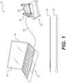
FIG. 1 is an elevated perspective view of an exemplary force analytic system in accordance with the instant disclosure. -
FIG. 2 is an elevated perspective view of an exemplary measuring device comprising part of the exemplary system ofFIG. 1 . -
FIG. 3 is an exploded view, from an elevated perspective, of the exemplary measuring device ofFIG. 2 . -
FIG. 4 is an exploded view, from a lowered perspective, of the exemplary measuring device ofFIG. 2 . -
FIG. 5 is an exploded view of the sled, levers, baseplate, and fasteners comprising a part of the exemplary measuring device ofFIG. 2 . -
FIG. 6 is a lowered perspective view of the sled ofFIG. 5 . -
FIG. 7 is an exemplary process flow diagram for a testing a medical device in accordance with the instant disclosure. -
FIG. 8 is a screen shot of an exemplary graphical user interface in accordance with the instant disclosure. - The exemplary embodiments of the present disclosure are described and illustrated below to encompass exemplary testing devices/systems, methods, displays, and outputs associated with the foregoing devices/systems. However, for clarity and precision, the exemplary embodiments as discussed below may include optional steps, methods, and features that one of ordinary skill should recognize as not being a requisite to fall within the scope of the present invention.
- Referencing
FIG. 1 , an exemplary forceanalytic system 100 includes ameasuring device 102 communicatively coupled to acomputer 104. The communicative coupling may be wired 103 or wireless between thecomputer 104 and themeasuring device 102, both wired and wireless connections being well known to those skilled in the art and need not be discussed in greater detail for purposes of brevity. - Referring to
FIGS. 2-6 , the exemplarymeasuring device 102 comprises aplatform 106 having a series of throughholes bottom surfaces bottom surfaces circumferential surface 118 delineating a rounded, rectangular boundary. A plurality offeet 120 are mounted to thebottom surface 116 viaindividual fasteners 122 such as, without limitation, threaded screws. Thefeet 120 are positioned in proximity to, but inset with respect to, the four corners of theplatform 106. In exemplary form, thefeet 120 may embody a frustro-pyramidal shape and be formed of an elastomeric or polymer material. But it should also be noted that thefeet 120 may embody any number of shapes and be fabricated from any number and variety of materials. In any event, thefeet 120 are mounted to theplatform 106 opposite the other components of themeasuring device 102. - A
vertical support 130 embodying a rectangular cuboid shape is mounted to theplatform 106 by threadedfasteners 132 extending from thebottom surface 116, through two of theholes 110, and above thetop surface 114. By way of example, the vertical support may be fabricated from a block of aluminum. In particular, a bottom face of thevertical support 130 includes a pair of threadedcavities 134 that are configured to receive portions of the threadedfasteners 132 that extend above thetop surface 114 in order to secure thevertical support 130 to theplatform 106. A dominant longitudinal dimension of thevertical support 130 extends perpendicularly with respect to thetop surface 114 so that amounting hole 140 extends parallel to thetop surface 114 and perpendicular with respect to thecavities 134. In exemplary form, themounting hole 140 is sized to receive a threadedfastener 142 that engages acorresponding cavity 143 of aload cell 144. An opposite side of theload cell 144 housing includes asecond cavity 145 to receive a second threadedfastener 146 that extends through apassage 148 in asled 150, thereby mounting the load cell to the sled. In this exemplary embodiment, theload cell 144 comprises a transducer creating electrical signals whose magnitude is directly proportional to the force applied to the load cell.Exemplary load cells 144 that may be used as part of the exemplary measuring device include, without limitation, the Mini Tension/Compression Force Sensor, MR04-2, commercially available from Mark-10 Corporation, 11 Dixon Avenue, Copiague, NY 11726 USA. - In exemplary form, the
sled 150 comprises a block U-shaped support, which may be fabricated from a solid block of aluminum, having a pair oftowers bridge 156. Proximate the corners of thebridge 156, where the bridge andtowers holes 158 configured to receivefasteners 160 to pivotally mount the sled to a series ofpivot levers 162. In exemplary form, thethrough holes 158 extend perpendicular to the dominant longitudinal dimensions of thebridge 156 and thetowers underside surface 164, generally opposite the direction that bothtowers cavities 166, with each cavity configured to receive a portion of arespective pivot lever 162. In this exemplary embodiment, two of the fourcavities 166 intersect a first of the throughholes 158, while the other two of the fourcavities 166 intersect a second of the throughholes 158. In this fashion, arespective fastener 160 extends through arespective hole 158 and through acorresponding hole 174 of each of two of the pivot levers 162 in order to pivotally mount thesled 150 to the levers. And the pivot levers 162 are also pivotally mounted to abaseplate 180 secured to thetop surface 114 of theplate 106. - It should be noted that the sled may alternatively be mounted to the baseplate using any number of structures that provide for movement between the sled and baseplate. By way of example, the pivot levers 162 may be replaced by a roller slide, a roller conveyor, ball bearings, magnetic levitation, and air bearings. These alternative structures are known in the art and need not be described in exhaustive detail in furtherance of brevity.
- By way of example, the
baseplate 180 comprises a solid rectangular cuboid that may be fabricated from a solid block of aluminum and has a pair of throughholes 182 located near respective upper corners on opposing surfaces. More specifically, the throughholes 182 extend between opposinglongitudinal surfaces 184, where the longitudinal opposed surfaces embody the dominant longitudinal dimension of thebaseplate 180. One of the connectingsurfaces baseplate 180, which spans thesurfaces 184, 186 through which theholes 182 extend, has fourcavities 196 formed therein. A series of threadedcavities 198 are formed through the second connectingsurface 190 and aligned to overlaprespective openings 112 of theplatform 106 and are configured to receivefasteners 200 that mount thebaseplate 180 to the platform. The second set ofcavities 196 is formed through the first connectingsurface 188 to expose the throughholes 182. In exemplary form, thecavities 196 are bounded by opposing planar surfaces 204 connected by a curved surface 206. As will be discussed in more detail hereafter, the dimensions of thecavities 198 allow pivotal motion of thelevers 162 so that thesled 150 may be repositioned with respect to thebaseplate 180. - In exemplary form, the
sled 150 is repositionable with respect to thebaseplate 180, which is stationary with respect to theplatform 106. In particular, thesled 150 is pivotally repositionable with respect to thebaseplate 180 by way of a connection to thelevers 162. Eachlever 162 comprises a pair of oblong,planar surfaces 210 that are spanned by constant heightperipheral surface 212. In this exemplary embodiment, the levers may be fabricated from aluminum. Theperipheral surface 212 includes a pair of planar surface segments that are spanned by arcuate surfaces having a semi-circular profile. Each oblongplanar surface 212 is identically sized and includes a pair ofholes 174 that interconnect to counterpart holes 158, 182 to delineate a pair of cylindrical channels that extend through thelevers 162 and respectively through thesled 150 andbaseplate 180. Each of these channels is sized to receive afastener respective fasteners 216 extend throughbaseplate holes 182 and extend through respectivelower holes 214 of thelevers 162, while a first end of eachlever 162 is positioned withinrespective cavities 198 of thebaseplate 180, thereby allowing thelever 162 to pivot with respect to thebaseplate 180 and around acollar 218 of thefasteners 216. Similarly,respective fasteners 160 extend throughsled holes 158 and extend through respectiveupper holes 158 of thelevers 162 while a second end of eachlever 162 is positioned withinrespective cavities 166 of thesled 150, thereby allowing thelever 162 to pivot with respect to thesled 150 and around acollar 220 of thefasteners 160. In this exemplary embodiment, the underside of thesled 150 includes a roundedrectangular recess 230 that outlines a roundedrectangular plateau 232 of thebaseplate 180. As will be discussed in more detail hereafter, relative motion between thesled 150 andbaseplate 180 is indicative of forces applied to atest conduit 240 resulting from resistance to insertion or withdrawal of amedical device test conduit 240. - According to the invention, the
test conduit 240 is secured to thesled 150 and comprises a tortuous, hollow pathway that is shaped to replicate or resemble a patient bodily channel. By way of example, thetest conduit 240 may be fabricated from any number of materials such as, without limitation, polymers, ceramics (including glass), metals, composites, and any other material capable of delineating a hollow pathway. By way of further example, thetest conduit 240 may embody a constant geometric profile (e.g., a circular profile) or may have profiles that vary along the length of the pathway. Opposing ends of thetest conduit 240 are open to provide for egress ofmedical instruments test conduit 240 to thesled 150, retention caps 246 are fastened to thesled 150. More specifically, each of the retention caps 246 (that may be fabricated from aluminum) and thetowers arcuate depressions test conduit 240 when the retention caps are mounted to the towers. Thearcuate depressions test conduit 240 in order to hold the test conduit in position with respect to thesled 150 when thecaps 246 are in place. In order to mount thecaps 246 to thesled 150, and thereby sandwich thetest conduit 240 between the caps and sled, each cap includes two throughholes 252 sized to receive corresponding threadedfasteners 254 that extend into corresponding threadedcavities 256 on the top of thetowers fasteners 254 through theholes 252 and into engagement with the threadedcavities 256 and torquing the fasteners is operative to mount thecaps 246 to thesled 150 and sandwich the test conduit therebetween so that relative motion between the test conduit, sled, and caps is minimized or eliminated. In this fashion, after thetest conduit 240 is secured in place, forces applied to thetest conduit 240 result in theload cell 144 generating outputs that are communicated to thecomputer 104 via thecommunication link 103. - Referring back to
FIG. 1 , the exemplary forceanalytic system 100 may be utilized to provide quantitative data as to the force required to cause insertion or withdrawal of a device through thetest conduit 240. By way of example, the device may comprise a medical device. But it should also be understood, however, that devices and articles other than medical devices may tested to evaluate insertion and withdrawal forces. These other exemplary devices and articles that may be tested include, without limitation, cables, wires, and any other substrate for which insertion and withdrawal forces are sought to be determined as being within the scope of the instant disclosure. - As mentioned previously, the
test conduit 240 may be fabricated from any number of materials and have any number of shapes and cross-sections. Regardless of the shape and material of thetest conduit 240, presuming the same test conduit is utilized to standardize the data received from theload cell 144 across multiple medical devices tested, the exemplary forceanalytic system 100 generates force data (in dynes) as a function of time when one inserts and/or withdraws amedical device analytic system 100 follows. - Referring to
FIG. 7 , as an initial matter, utilizing the exemplary forceanalytic system 100 presumes the measuringdevice 102 is fully assembled to allow thesled 150 to be repositioned with respect to thebaseplate 180. Likewise, it is presumed that thetest conduit 240 is secured to thesled 150 so that relative movement between the test conduit and sled is avoided. Moreover, it is presumed that theload cell 144 is communicatively coupled to thecomputer 104 and that the computer is programmed with a data acquisition program utilizing the output signals from the load cell to calculate a resultant force. With these presumptions in place, utilizing the exemplary forceanalytic system 100 will be described in exemplary form. - For purposes of explanation only, the following exemplary description of a
process 400 for using the forceanalytic system 100 makes use of two or more catheters as the testedmedical devices medical devices medical device - Before any
medical device prefatory step 402 includes initializing and verifying thecommunication link 103 between theload cell 144 and thecomputer 104 is operative. In order to do so, one may establish a wired or wirelessdata communication link 103 between thecomputer 104 andload cell 144 so that electrical signals output from the load cell are communicated to the computer and utilized by the computer to compute force acting on theload cell 144.Post communication link 103 initialization and verification, the process includes a zeroingstep 404 to ensure signals from theload cell 144, transmitted via thecommunication link 103, to thecomputer 104 account for a static state (i.e., to zero the reading from the load cell 144) where nomedical insertion device test conduit 240. In other words, theload cell 144 may be sending signals to thecomputer 104, but these signals may represent forces that are constantly acting on the load cell and need to be factored out during the insertion force testing sequence. After zeroing the signals from theload cell 144 to represent a static state, the force testing portion of theprocess 400 may commence. - As part of this
exemplary embodiment 100 andtesting process 400, thecomputer 104 includes a data acquisition program operative to record electrical signals from the load cell 144 (via the communication link 103) and utilizes these signals to compute applied force. The computed applied force is representative of the amount of force at a given time required to cause themedical device test conduit 240, whether the traversal is the result of insertion into or withdrawal from the test conduit. As part of the recordation of these electrical signals from theload cell 144, thecomputer 104 includes an internal clock communicating with the data acquisition program to allow for data acquisition as a function of time. Specifically, the data acquisition program of thecomputer 104 includes a graphicaluser interface component 107 that may be displayed on acomputer monitor 109 or any associated electronic visual display communicatively coupled to thecomputer 104. - Referring to
FIG. 8 , an exemplary graphical user interface (GUI)component 107 may include a firstnumerical display 430 providing data representative of the maximum insertion force of a first testedmedical device 300 throughout thetesting process 400. A secondnumerical display 432 of theGUI component 107 may provide data representative of the maximum removal/withdrawal force of the first testedmedical device 300 throughout thetesting process 400. TheGUI component 107 may also include abutton 434 that may be activated using a cursor (via a mouse or touchpad) associated with thecomputer 104 to commence adata acquisition step 406. Data is acquired from theload cell 144 as a function of time while a user inserts the tested medical device 300 (e.g., catheter) into the open end of the test conduit opposite theload cell 144. As the firstmedical device 300 is inserted into thetest conduit 240, a firstgraphical display 436 may depict a continuous series of data points reflecting how insertion force (measured in dynes) changes with respect to time (measured in milliseconds). In exemplary form, the data points are displayed on thegraphical display 436 in real-time. Given the variance in scale that may be depicted as part of thegraphical display 436 to account for the test time and maximum forces measured, which may make precise reading of the firstgraphical display 436 more difficult, theGUI component 107 may also include a first magnifiedview window 438 that may display in real-time a running and changing measured force as a function of time for a snippet range (approximately a 200 millisecond band) across the testing total time of the first testedmedical device 300. This first magnifiedview window 438 provides the advantage of more precise, real-time viewing of the measured force as a function of time. Depending upon the desired insertion length chosen by a user for the firstmedical device 300 tested, the insertion may be stopped and withdrawal of the first medical device commenced. Throughout thetesting process 400, the data acquisition program tracks/records the greatest insertion force calculated and the greatest withdrawal forced calculated. These two maximum forces are updated in real-time in the respectivenumerical displays stop button 440 associated with theGUI component 107 is activated (using a cursor associated with the computer 104) to concludedata acquisition 408 associated with the first testedmedical device 300. - As is depicted in the first
graphical display 436, positive calculated numerical forces are indicative of insertion forces needed to direct the first testedmedical device 300 through thetest conduit 240 in a direction toward theload cell 144. Conversely, negative calculated numerical forces are indicative of withdrawal forces needed to direct the first testedmedical device 300 through thetest conduit 240 in a direction away from theload cell 144. A zero calculated numerical force represents a state where either the first testedmedical device 300 is stationary, or where the medical device is moving along thetest conduit 240 without measurable resistance, or where the medical device experiences rebound forces resulting from linear compression of the device itself. - As is reflected by the first graphical display436, the first
medical device 300 was inserted into thetest conduit 240 and began applying a force to thetest conduit 240 andload cell 144 at approximately 550 milliseconds and continued applying some positive force until reaching 1000 milliseconds. During this insertion traversal, the maximum insertion force calculated is 128 dynes, which is displayed in the firstnumerical display 430. After reaching maximum insertion (or a predetermined insertion location or length), themedical device 300 may be withdrawn from thetest conduit 240. As is reflected in the firstgraphical display 436, withdrawal of the firstmedical device 300 took approximately 100 milliseconds, with a maximum withdrawal force calculated as -48 dynes. This maximum withdrawal force is displayed in the secondnumerical display 432 as the absolute value of the calculated maximum withdrawal force. Post completion of the testing and withdrawal of the firstmedical device 300, the testing of the second medical device may commence atstep 410. - The exemplary graphical user interface (GUI)
component 107 may include a thirdnumerical display 450 providing data representative of the maximum insertion force of a second testedmedical device 302 throughout thetesting process 400. A fourthnumerical display 452 of theGUI component 107 may provide data representative of the maximum removal/withdrawal force of the second testedmedical device 302 throughout thetesting process 400. TheGUI component 107 may also include acomparative button 454 that may be activated using a cursor (via a mouse or touchpad) associated with thecomputer 104 to commence thedata acquisition step 410 for the secondmedical device 302. - Data is acquired from the
load cell 144 as a function of time while a user inserts the tested medical device 302 (e.g., catheter) into the open end of the test conduit opposite theload cell 144. As the secondmedical device 302 is inserted into thetest conduit 240, a secondgraphical display 456 depicts a continuous series of data points reflecting how insertion force (measured in dynes) changes with respect to time (measured in milliseconds). In exemplary form, the data points are displayed on thegraphical display 456 in real-time. Given the variance in scale that may be depicted as part of the graphical display to account for the test time and maximum forces measured, which may make precise reading of the secondgraphical display 456 more difficult, theGUI component 107 may also include a second magnifiedview window 458 that may display in real-time a running and changing calculated force as a function of time for a snippet range (approximately a 200 millisecond band) across the testing total time of the second testedmedical device 302. This second magnifiedview window 458 provides the advantage of more precise, real-time viewing of the measured force as a function of time. Depending upon the desired insertion length chosen by a user for the secondmedical device 302 tested, the insertion may be stopped and withdrawal of the second medical device commenced. Throughout thetesting process 400, the data acquisition program tracks/records the greatest insertion force calculated and the greatest withdrawal forced calculated for the secondmedical device 302. These two maximum forces are updated in real-time in the respectivenumerical displays comparative stop button 460 associated with theGUI component 107 is activated (using a cursor associated with the computer 104) to concludedata acquisition 412 associated with the second testedmedical device 302. - As is depicted in the second
graphical display 456, positive calculated numerical forces are indicative of insertion forces needed to direct the second testedmedical device 302 through thetest conduit 240 in a direction toward theload cell 144. Conversely, negative calculated numerical forces are indicative of withdrawal forces needed to direct the second testedmedical device 302 through thetest conduit 240 in a direction away from theload cell 144. A zero calculated numerical force represents a state where either the second testedmedical device 302 is stationary, or where the medical device is moving along thetest conduit 240 without measurable resistance, or where the medical device experiences rebound forces resulting from linear compression of the device itself. As is reflected by the secondgraphical display 456, the secondmedical device 302 was inserted into thetest conduit 240 and began applying a force to the test conduit andload cell 144 at approximately 350 milliseconds and continued applying some positive force until reaching 825 milliseconds. During this insertion traversal, the maximum insertion force calculated was 328.5 dynes, which is displayed in the thirdnumerical display 450. After reaching maximum insertion (or a predetermined insertion location or length), themedical device 302 may be withdrawn from thetest conduit 240. As is reflected in the secondgraphical display 456, withdrawal of the secondmedical device 302 took approximately 150 milliseconds, with a maximum withdrawal force being calculated as -128.5 dynes. This maximum withdrawal force is displayed in the fourthnumerical display 452 as the absolute value of the calculated maximum withdrawal force for the secondmedical device 302. Post completion of the withdrawal of the secondmedical device 302 from thetest conduit 240, theprocess 400 is concluded. - It should be noted that the foregoing fasteners may be fabricated from any number of materials including, without limitation, metals such aluminum, steel, titanium, and steel alloys. It should also be noted that while many of the foregoing components are described as being fabricated from blocks of aluminum (and subsequently machined), it is also within the scope of the invention for these materials to be fabricated from materials other than aluminum such as, without limitation, polymers, composites, and metals and metal alloys other than pure aluminum.
- Following from the above description, it should be apparent to those of ordinary skill in the art that, while the methods, devices, and systems herein described constitute exemplary embodiments of the present disclosure, the embodiments described herein are not limited to any precise embodiment and that changes may be made to such embodiments without departing from the scope of the disclosure as defined by the claims. Additionally, it is to be understood that the invention is defined by the claims and it is not intended that any limitations or elements describing the exemplary embodiments set forth herein are to be incorporated into the interpretation of any claim element unless such limitation or element is explicitly stated. Likewise, it is to be understood that it is not necessary to meet any or all of the identified advantages or objects of the invention disclosed herein in order to fall within the scope of any claims, since the invention is defined by the claims and since inherent and/or unforeseen advantages of the present exemplary embodiments may exist even though they may not have been explicitly discussed herein.
Claims (19)
- A force measuring system (100) comprising:a tortuous conduit (240), having a static shaped hollow pathway replicating or resembling a patient bodily channel, operatively coupled to a transducer; and,a computer (104) communicatively coupled to the transducer, the computer (104) programmed to utilize signals output from the transducer to calculate forces acting on the transducer, the computer (104) programmed to support a graphical user interface (107) for displaying the calculated forces;wherein a first portion of the transducer is mounted to a base (180), and a second portion of the transducer is mounted to a sled (150) repositionably mounted to the base (180).
- The measuring system (100) of claim 1, wherein:the tortuous conduit (240) is removably mounted to the sled (150); and,the sled (150) includes a pair of upstanding arms (152, 154) that cooperatively engage a retention cap (246) to selectively mount the tortuous conduit (240) to the sled (150).
- The measuring system (100) of claim 1, wherein the sled (150) is at least one of pivotally repositionable and slidably repositionable with respect to the base (180).
- The measuring system (100) of claim 3, wherein:the sled (150) is pivotally repositionable with respect to the base (180); and,a lever operatively couples the sled (150) and the base (180) and provides for the sled (150) to pivot with respect to the base (180).
- The measuring system (100) of claim 4, wherein the lever comprises a plurality of levers (162).
- The measuring system (100) of claim 4, wherein:at least one of the sled (150) and the base (180) includes a cavity (166, 196) into which the lever is at least partially inserted;the lever includes a pair of hollowed areas (174, 214) configured to receive cylindrical pins (160, 216);the sled (150) includes a sled opening (158) sized to receive a first one of the cylindrical pins (160); and,the base (180) includes a base opening (182) sized to receive a second one of the cylindrical pins (216).
- The measuring system (100) of claim 3, wherein:the sled (150) is slidably repositionable with respect to the stationary base (180); and,a slide operatively couples the sled (150) and the stationary base (180) and provides for the sled (150) to slide with respect to the stationary base (180).
- The measuring system (100) of any one of claims 1 to 7, wherein the transducer comprises a load cell (144).
- A process for comparing at least one of insertion and withdrawal forces associated with at least two devices using a device as defined in claim 1, the process comprising:inserting a first device into the tortuous conduit (240);recording insertion data indicative of insertion forces applied to the first device traveling in a first direction in the tortuous conduit (240);withdrawing the first device from the tortuous conduit (240);recording withdrawal data indicative of withdrawal forces applied to the first device traveling in a second direction in the tortuous conduit (240), where the second direction is generally opposite the first direction;repeating the foregoing steps by replacing the first device with a second device; and,comparing the insertion data and withdrawal data between at least the first and second devices.
- The process of claim 9, wherein:the tortuous conduit (240) is rigidly mounted to a load cell (144);the load cell (144) is configured to output signals having a magnitude proportional to a force applied to the tortuous conduit (240); and,the load cell (144) is communicatively coupled to a programmed computer (104) utilizing the signals and calculating the insertion forces and calculating the withdrawal forces.
- The process of claim 10, wherein:the programmed computer (104) supports a graphical user interface (107); and,the graphical user interface (107) displays the insertion forces and the withdrawal forces.
- The process of claim 11, wherein:the insertion forces include a maximum insertion force;the withdrawal forces include a maximum withdrawal force;the graphical user interface (107) displays the maximum insertion force and the maximum insertion force as part of a graph depicting force as a function of time; and,the graphical user interface (107) displays a separate graph for the first medical device and a second medical device.
- The process of claim 12, wherein:the graphical user interface (107) also displays the maximum insertion force separate from the graph;the graphical user interface (107) also displays the maximum withdrawal force separate from the graph; and,the graphical user interface (107) displays a separate reading for the maximum withdrawal force and the maximum insertion force for the first medical device and a second medical device.
- The process of either one of claims 12 or 13, wherein:the insertion forces are displayed on the graphical user interface (107) in real-time; and,the withdrawal forces are displayed on the graphical user interface (107) in real-time.
- The process of any of claims 11-14, wherein:the graphical user interface (107) includes a button (434, 454) to be clicked for initiating recordation of the insertion data; and,the graphical user interface (107) includes a button (440, 460) to be clicked for concluding recordation of the withdrawal data.
- The process of claim 15, wherein the button initiating recordation of the insertion data is the same as the button concluding recordation of the withdrawal data.
- The process of claim 15, wherein graphical user interface (107) includes a separate button (434) initiating recordation of the insertion data for first device and a separate button (460) for concluding recordation of the withdrawal data for the second device.
- The process of any one of claims 9-17, wherein the tortuous conduit is representative of a bodily conduit the first and second devices would traverse when used during a medical procedure.
- The process of any one of claims 9-18, wherein the first and second devices comprise a first catheter and a second catheter.
Applications Claiming Priority (2)
| Application Number | Priority Date | Filing Date | Title |
|---|---|---|---|
| US15/434,900 US11248973B2 (en) | 2017-02-16 | 2017-02-16 | Insertion and withdrawal force measurement system |
| PCT/US2018/015167 WO2018151916A1 (en) | 2017-02-16 | 2018-01-25 | Insertion and withdrawal force measurement system |
Publications (4)
| Publication Number | Publication Date |
|---|---|
| EP3583395A1 EP3583395A1 (en) | 2019-12-25 |
| EP3583395A4 EP3583395A4 (en) | 2020-12-30 |
| EP3583395C0 EP3583395C0 (en) | 2024-04-10 |
| EP3583395B1 true EP3583395B1 (en) | 2024-04-10 |
Family
ID=63106380
Family Applications (1)
| Application Number | Title | Priority Date | Filing Date |
|---|---|---|---|
| EP18754326.9A Active EP3583395B1 (en) | 2017-02-16 | 2018-01-25 | Insertion and withdrawal force measurement system |
Country Status (5)
| Country | Link |
|---|---|
| US (1) | US11248973B2 (en) |
| EP (1) | EP3583395B1 (en) |
| JP (1) | JP2020509359A (en) |
| KR (1) | KR20190118578A (en) |
| WO (1) | WO2018151916A1 (en) |
Families Citing this family (1)
| Publication number | Priority date | Publication date | Assignee | Title |
|---|---|---|---|---|
| CN112504529A (en) * | 2020-11-11 | 2021-03-16 | 上海平高天灵开关有限公司 | Force measuring device for main shaft assembly contact piece |
Family Cites Families (19)
| Publication number | Priority date | Publication date | Assignee | Title |
|---|---|---|---|---|
| JPS5140932B2 (en) * | 1971-12-29 | 1976-11-06 | ||
| DE19645334B4 (en) | 1996-11-04 | 2004-01-22 | Kunststoff-Zentrum in Leipzig gemeinnützige Gesellschaft mbH | Method and device for testing the kink stability |
| GB0415223D0 (en) * | 2004-07-07 | 2004-08-11 | Sensornet Ltd | Intervention rod |
| US6981945B1 (en) | 2004-11-12 | 2006-01-03 | Artann Laboratories, Inc. | Colonoscope handgrip with force and torque monitor |
| US7765841B2 (en) * | 2006-02-16 | 2010-08-03 | Oes, Inc. | Quality analysis of tube bending processes including mandrel fault detection |
| US8052621B2 (en) | 2006-02-22 | 2011-11-08 | Hansen Medical, Inc. | Method of sensing forces on a working instrument |
| JP4878513B2 (en) * | 2006-03-27 | 2012-02-15 | 国立大学法人 名古屋工業大学 | Apparatus and method for measuring compressive force of flexible linear body |
| JP4878526B2 (en) * | 2006-09-05 | 2012-02-15 | 国立大学法人 名古屋工業大学 | Apparatus for measuring compressive force of flexible linear body |
| JP4905691B2 (en) * | 2007-03-02 | 2012-03-28 | 国立大学法人 名古屋工業大学 | Apparatus for measuring compressive force of flexible linear body |
| JP5171535B2 (en) | 2007-12-14 | 2013-03-27 | Ntn株式会社 | Load detection device and load detection method |
| US7770466B2 (en) | 2008-07-02 | 2010-08-10 | Abbott Cardiovascular Systems Inc. | Method for measuring stent dislodgement force |
| US8915908B2 (en) | 2009-03-20 | 2014-12-23 | Atricure, Inc. | Cryogenic probe |
| DE102011075785A1 (en) * | 2011-05-13 | 2012-11-15 | Karl Storz Gmbh & Co. Kg | Medical tubular shaft instrument and method for producing a power transmission element thereof |
| US9458905B2 (en) * | 2012-09-20 | 2016-10-04 | Steelcase Inc. | Spring assembly and method |
| JP2014077691A (en) * | 2012-10-10 | 2014-05-01 | Ntn Corp | Calibration device of measuring device and calibration method |
| US9618069B2 (en) * | 2013-05-21 | 2017-04-11 | The Boeing Company | Adjustable compression, adjustable tension rod indicator, and adjustable extension rod |
| EP2848911B1 (en) | 2013-09-12 | 2016-10-19 | BIOTRONIK SE & Co. KG | Test apparatus with gimbaled mount for catheters |
| CN105916529B (en) * | 2014-01-21 | 2019-06-25 | 心脏起搏器股份公司 | The medical device mixed polymer structure and coating of lubricity and durability with raising |
| US20170348496A1 (en) | 2014-12-17 | 2017-12-07 | Norton (Waterford) Limited | Can and Actuator Assembly |
-
2017
- 2017-02-16 US US15/434,900 patent/US11248973B2/en active Active
-
2018
- 2018-01-25 KR KR1020197023840A patent/KR20190118578A/en not_active Application Discontinuation
- 2018-01-25 JP JP2019543757A patent/JP2020509359A/en not_active Ceased
- 2018-01-25 WO PCT/US2018/015167 patent/WO2018151916A1/en unknown
- 2018-01-25 EP EP18754326.9A patent/EP3583395B1/en active Active
Also Published As
| Publication number | Publication date |
|---|---|
| KR20190118578A (en) | 2019-10-18 |
| JP2020509359A (en) | 2020-03-26 |
| US20180231426A1 (en) | 2018-08-16 |
| US11248973B2 (en) | 2022-02-15 |
| WO2018151916A1 (en) | 2018-08-23 |
| EP3583395C0 (en) | 2024-04-10 |
| EP3583395A4 (en) | 2020-12-30 |
| EP3583395A1 (en) | 2019-12-25 |
Similar Documents
| Publication | Publication Date | Title |
|---|---|---|
| JP7116136B2 (en) | A system for collecting vascular-related data | |
| US8257269B2 (en) | Apparatus for analysing pulse using array of pressure sensors | |
| Takashima et al. | Contact and friction between catheter and blood vessel | |
| CN103796578B (en) | Ink vessel transfusing method for sensing and system | |
| EP0506520B1 (en) | Blood flow detection apparatus | |
| Mayhew et al. | Performance characteristics of the Kin-Com® dynamometer | |
| US20070093989A1 (en) | Method and Apparatus for Reducing Errors in Screening-Test Administration | |
| WO2006061814A1 (en) | Method and apparatus for finding the tubular organs blood velocity and flow and related parameters | |
| RU2621414C2 (en) | Simulation system for medical procedure with visualization control, method for control of simulation system for medical procedure and simulation system operating unit | |
| EP3583395B1 (en) | Insertion and withdrawal force measurement system | |
| EP2747694B1 (en) | Method or determining the shape of a surgical instrument and surgical instrument having a deformable body | |
| Xu et al. | A miniature multiaxis force/torque sensor for acupuncture | |
| Hartquist et al. | Quantification of the flexural rigidity of peripheral arterial endovascular catheters and sheaths | |
| R Carrick et al. | Metrological performance of instruments used in clinical evaluation of balance | |
| CN107300569A (en) | The acquisition methods of dew point of hydrogen temperature in generator | |
| Mencattelli et al. | Customized load cell for three-dimensional force-moment measurements in orthodontics | |
| Jex | A proposed set of standardized sub-critical tasks for tracking workload calibration | |
| JP2021529950A (en) | Tester speed verification system | |
| US20220327962A1 (en) | Testing surface for advanced medical training | |
| Walendziuk | Measurement uncertainty analysis of the strain gauge based stabilographic platform | |
| US20240215844A1 (en) | Methodology for Assessing Coronary Flow and Microvascular System Through Pressurewires -- Pressure Dilution Curve | |
| Han et al. | Force Model for Needle-Tissue Interaction | |
| Cebeiro et al. | Low flow measurement for infusion pumps: implementation and uncertainty determination of the normalized method | |
| Choi et al. | Potential errors in fiber length measurements resulting from lever arm rotation during mechanical testing of muscle cells | |
| Poursartip et al. | Performance Evaluation of a Sensorized Arthroscopic Grasper |
Legal Events
| Date | Code | Title | Description |
|---|---|---|---|
| STAA | Information on the status of an ep patent application or granted ep patent |
Free format text: STATUS: THE INTERNATIONAL PUBLICATION HAS BEEN MADE |
|
| PUAI | Public reference made under article 153(3) epc to a published international application that has entered the european phase |
Free format text: ORIGINAL CODE: 0009012 |
|
| STAA | Information on the status of an ep patent application or granted ep patent |
Free format text: STATUS: REQUEST FOR EXAMINATION WAS MADE |
|
| 17P | Request for examination filed |
Effective date: 20190808 |
|
| AK | Designated contracting states |
Kind code of ref document: A1 Designated state(s): AL AT BE BG CH CY CZ DE DK EE ES FI FR GB GR HR HU IE IS IT LI LT LU LV MC MK MT NL NO PL PT RO RS SE SI SK SM TR |
|
| AX | Request for extension of the european patent |
Extension state: BA ME |
|
| DAV | Request for validation of the european patent (deleted) | ||
| DAX | Request for extension of the european patent (deleted) | ||
| RAP1 | Party data changed (applicant data changed or rights of an application transferred) |
Owner name: C.R. BARD, INC. |
|
| REG | Reference to a national code |
Ref country code: DE Ref legal event code: R079 Ref document number: 602018067865 Country of ref document: DE Free format text: PREVIOUS MAIN CLASS: G01L0005040000 Ipc: G01L0005000000 Ref country code: DE Ref legal event code: R079 Free format text: PREVIOUS MAIN CLASS: G01L0005040000 Ipc: G01L0005000000 |
|
| A4 | Supplementary search report drawn up and despatched |
Effective date: 20201126 |
|
| RIC1 | Information provided on ipc code assigned before grant |
Ipc: G01L 5/00 20060101AFI20201123BHEP Ipc: A61B 90/00 20160101ALI20201123BHEP |
|
| STAA | Information on the status of an ep patent application or granted ep patent |
Free format text: STATUS: EXAMINATION IS IN PROGRESS |
|
| 17Q | First examination report despatched |
Effective date: 20221104 |
|
| GRAP | Despatch of communication of intention to grant a patent |
Free format text: ORIGINAL CODE: EPIDOSNIGR1 |
|
| STAA | Information on the status of an ep patent application or granted ep patent |
Free format text: STATUS: GRANT OF PATENT IS INTENDED |
|
| INTG | Intention to grant announced |
Effective date: 20231110 |
|
| GRAS | Grant fee paid |
Free format text: ORIGINAL CODE: EPIDOSNIGR3 |
|
| GRAA | (expected) grant |
Free format text: ORIGINAL CODE: 0009210 |
|
| STAA | Information on the status of an ep patent application or granted ep patent |
Free format text: STATUS: THE PATENT HAS BEEN GRANTED |
|
| AK | Designated contracting states |
Kind code of ref document: B1 Designated state(s): AL AT BE BG CH CY CZ DE DK EE ES FI FR GB GR HR HU IE IS IT LI LT LU LV MC MK MT NL NO PL PT RO RS SE SI SK SM TR |
|
| REG | Reference to a national code |
Ref country code: GB Ref legal event code: FG4D |
|
| REG | Reference to a national code |
Ref country code: CH Ref legal event code: EP |
|
| REG | Reference to a national code |
Ref country code: DE Ref legal event code: R096 Ref document number: 602018067865 Country of ref document: DE |
|
| REG | Reference to a national code |
Ref country code: IE Ref legal event code: FG4D |
|
| U01 | Request for unitary effect filed |
Effective date: 20240425 |
|
| U07 | Unitary effect registered |
Designated state(s): AT BE BG DE DK EE FI FR IT LT LU LV MT NL PT SE SI Effective date: 20240517 |