EP3583000B1 - Refrigerating or warming apparatus, and vehicle - Google Patents
Refrigerating or warming apparatus, and vehicle Download PDFInfo
- Publication number
- EP3583000B1 EP3583000B1 EP18754627.0A EP18754627A EP3583000B1 EP 3583000 B1 EP3583000 B1 EP 3583000B1 EP 18754627 A EP18754627 A EP 18754627A EP 3583000 B1 EP3583000 B1 EP 3583000B1
- Authority
- EP
- European Patent Office
- Prior art keywords
- machine room
- refrigerating
- console
- cavity
- warming apparatus
- Prior art date
- Legal status (The legal status is an assumption and is not a legal conclusion. Google has not performed a legal analysis and makes no representation as to the accuracy of the status listed.)
- Active
Links
Images


Classifications
-
- B—PERFORMING OPERATIONS; TRANSPORTING
- B60—VEHICLES IN GENERAL
- B60H—ARRANGEMENTS OF HEATING, COOLING, VENTILATING OR OTHER AIR-TREATING DEVICES SPECIALLY ADAPTED FOR PASSENGER OR GOODS SPACES OF VEHICLES
- B60H3/00—Other air-treating devices
-
- B—PERFORMING OPERATIONS; TRANSPORTING
- B60—VEHICLES IN GENERAL
- B60H—ARRANGEMENTS OF HEATING, COOLING, VENTILATING OR OTHER AIR-TREATING DEVICES SPECIALLY ADAPTED FOR PASSENGER OR GOODS SPACES OF VEHICLES
- B60H1/00—Heating, cooling or ventilating [HVAC] devices
- B60H1/00507—Details, e.g. mounting arrangements, desaeration devices
- B60H1/00514—Details of air conditioning housings
- B60H1/0055—Details of air conditioning housings the housing or parts thereof being integrated in other devices, e.g. dashboard
-
- B—PERFORMING OPERATIONS; TRANSPORTING
- B60—VEHICLES IN GENERAL
- B60H—ARRANGEMENTS OF HEATING, COOLING, VENTILATING OR OTHER AIR-TREATING DEVICES SPECIALLY ADAPTED FOR PASSENGER OR GOODS SPACES OF VEHICLES
- B60H1/00—Heating, cooling or ventilating [HVAC] devices
- B60H1/00507—Details, e.g. mounting arrangements, desaeration devices
- B60H1/00592—Add-on devices, e.g. heat/cooling boxes, compartment dividers, upgrade sets
-
- B—PERFORMING OPERATIONS; TRANSPORTING
- B60—VEHICLES IN GENERAL
- B60R—VEHICLES, VEHICLE FITTINGS, OR VEHICLE PARTS, NOT OTHERWISE PROVIDED FOR
- B60R7/00—Stowing or holding appliances inside vehicle primarily intended for personal property smaller than suit-cases, e.g. travelling articles, or maps
- B60R7/04—Stowing or holding appliances inside vehicle primarily intended for personal property smaller than suit-cases, e.g. travelling articles, or maps in driver or passenger space, e.g. using racks
-
- F—MECHANICAL ENGINEERING; LIGHTING; HEATING; WEAPONS; BLASTING
- F25—REFRIGERATION OR COOLING; COMBINED HEATING AND REFRIGERATION SYSTEMS; HEAT PUMP SYSTEMS; MANUFACTURE OR STORAGE OF ICE; LIQUEFACTION SOLIDIFICATION OF GASES
- F25D—REFRIGERATORS; COLD ROOMS; ICE-BOXES; COOLING OR FREEZING APPARATUS NOT OTHERWISE PROVIDED FOR
- F25D17/00—Arrangements for circulating cooling fluids; Arrangements for circulating gas, e.g. air, within refrigerated spaces
- F25D17/04—Arrangements for circulating cooling fluids; Arrangements for circulating gas, e.g. air, within refrigerated spaces for circulating air, e.g. by convection
- F25D17/06—Arrangements for circulating cooling fluids; Arrangements for circulating gas, e.g. air, within refrigerated spaces for circulating air, e.g. by convection by forced circulation
- F25D17/067—Evaporator fan units
-
- F—MECHANICAL ENGINEERING; LIGHTING; HEATING; WEAPONS; BLASTING
- F25—REFRIGERATION OR COOLING; COMBINED HEATING AND REFRIGERATION SYSTEMS; HEAT PUMP SYSTEMS; MANUFACTURE OR STORAGE OF ICE; LIQUEFACTION SOLIDIFICATION OF GASES
- F25D—REFRIGERATORS; COLD ROOMS; ICE-BOXES; COOLING OR FREEZING APPARATUS NOT OTHERWISE PROVIDED FOR
- F25D27/00—Lighting arrangements
-
- F—MECHANICAL ENGINEERING; LIGHTING; HEATING; WEAPONS; BLASTING
- F25—REFRIGERATION OR COOLING; COMBINED HEATING AND REFRIGERATION SYSTEMS; HEAT PUMP SYSTEMS; MANUFACTURE OR STORAGE OF ICE; LIQUEFACTION SOLIDIFICATION OF GASES
- F25D—REFRIGERATORS; COLD ROOMS; ICE-BOXES; COOLING OR FREEZING APPARATUS NOT OTHERWISE PROVIDED FOR
- F25D29/00—Arrangement or mounting of control or safety devices
- F25D29/003—Arrangement or mounting of control or safety devices for movable devices
-
- F—MECHANICAL ENGINEERING; LIGHTING; HEATING; WEAPONS; BLASTING
- F25—REFRIGERATION OR COOLING; COMBINED HEATING AND REFRIGERATION SYSTEMS; HEAT PUMP SYSTEMS; MANUFACTURE OR STORAGE OF ICE; LIQUEFACTION SOLIDIFICATION OF GASES
- F25D—REFRIGERATORS; COLD ROOMS; ICE-BOXES; COOLING OR FREEZING APPARATUS NOT OTHERWISE PROVIDED FOR
- F25D29/00—Arrangement or mounting of control or safety devices
- F25D29/005—Mounting of control devices
-
- B—PERFORMING OPERATIONS; TRANSPORTING
- B60—VEHICLES IN GENERAL
- B60N—SEATS SPECIALLY ADAPTED FOR VEHICLES; VEHICLE PASSENGER ACCOMMODATION NOT OTHERWISE PROVIDED FOR
- B60N3/00—Arrangements or adaptations of other passenger fittings, not otherwise provided for
- B60N3/10—Arrangements or adaptations of other passenger fittings, not otherwise provided for of receptacles for food or beverages, e.g. refrigerated
- B60N3/104—Arrangements or adaptations of other passenger fittings, not otherwise provided for of receptacles for food or beverages, e.g. refrigerated with refrigerating or warming systems
-
- F—MECHANICAL ENGINEERING; LIGHTING; HEATING; WEAPONS; BLASTING
- F25—REFRIGERATION OR COOLING; COMBINED HEATING AND REFRIGERATION SYSTEMS; HEAT PUMP SYSTEMS; MANUFACTURE OR STORAGE OF ICE; LIQUEFACTION SOLIDIFICATION OF GASES
- F25D—REFRIGERATORS; COLD ROOMS; ICE-BOXES; COOLING OR FREEZING APPARATUS NOT OTHERWISE PROVIDED FOR
- F25D2201/00—Insulation
- F25D2201/10—Insulation with respect to heat
- F25D2201/14—Insulation with respect to heat using subatmospheric pressure
-
- F—MECHANICAL ENGINEERING; LIGHTING; HEATING; WEAPONS; BLASTING
- F25—REFRIGERATION OR COOLING; COMBINED HEATING AND REFRIGERATION SYSTEMS; HEAT PUMP SYSTEMS; MANUFACTURE OR STORAGE OF ICE; LIQUEFACTION SOLIDIFICATION OF GASES
- F25D—REFRIGERATORS; COLD ROOMS; ICE-BOXES; COOLING OR FREEZING APPARATUS NOT OTHERWISE PROVIDED FOR
- F25D23/00—General constructional features
- F25D23/003—General constructional features for cooling refrigerating machinery
-
- F—MECHANICAL ENGINEERING; LIGHTING; HEATING; WEAPONS; BLASTING
- F25—REFRIGERATION OR COOLING; COMBINED HEATING AND REFRIGERATION SYSTEMS; HEAT PUMP SYSTEMS; MANUFACTURE OR STORAGE OF ICE; LIQUEFACTION SOLIDIFICATION OF GASES
- F25D—REFRIGERATORS; COLD ROOMS; ICE-BOXES; COOLING OR FREEZING APPARATUS NOT OTHERWISE PROVIDED FOR
- F25D23/00—General constructional features
- F25D23/006—General constructional features for mounting refrigerating machinery components
-
- F—MECHANICAL ENGINEERING; LIGHTING; HEATING; WEAPONS; BLASTING
- F25—REFRIGERATION OR COOLING; COMBINED HEATING AND REFRIGERATION SYSTEMS; HEAT PUMP SYSTEMS; MANUFACTURE OR STORAGE OF ICE; LIQUEFACTION SOLIDIFICATION OF GASES
- F25D—REFRIGERATORS; COLD ROOMS; ICE-BOXES; COOLING OR FREEZING APPARATUS NOT OTHERWISE PROVIDED FOR
- F25D2323/00—General constructional features not provided for in other groups of this subclass
- F25D2323/002—Details for cooling refrigerating machinery
- F25D2323/0026—Details for cooling refrigerating machinery characterised by the incoming air flow
- F25D2323/00265—Details for cooling refrigerating machinery characterised by the incoming air flow through the front top part
-
- F—MECHANICAL ENGINEERING; LIGHTING; HEATING; WEAPONS; BLASTING
- F25—REFRIGERATION OR COOLING; COMBINED HEATING AND REFRIGERATION SYSTEMS; HEAT PUMP SYSTEMS; MANUFACTURE OR STORAGE OF ICE; LIQUEFACTION SOLIDIFICATION OF GASES
- F25D—REFRIGERATORS; COLD ROOMS; ICE-BOXES; COOLING OR FREEZING APPARATUS NOT OTHERWISE PROVIDED FOR
- F25D2323/00—General constructional features not provided for in other groups of this subclass
- F25D2323/002—Details for cooling refrigerating machinery
- F25D2323/0027—Details for cooling refrigerating machinery characterised by the out-flowing air
- F25D2323/00276—Details for cooling refrigerating machinery characterised by the out-flowing air from the bottom
-
- F—MECHANICAL ENGINEERING; LIGHTING; HEATING; WEAPONS; BLASTING
- F25—REFRIGERATION OR COOLING; COMBINED HEATING AND REFRIGERATION SYSTEMS; HEAT PUMP SYSTEMS; MANUFACTURE OR STORAGE OF ICE; LIQUEFACTION SOLIDIFICATION OF GASES
- F25D—REFRIGERATORS; COLD ROOMS; ICE-BOXES; COOLING OR FREEZING APPARATUS NOT OTHERWISE PROVIDED FOR
- F25D2323/00—General constructional features not provided for in other groups of this subclass
- F25D2323/002—Details for cooling refrigerating machinery
- F25D2323/0027—Details for cooling refrigerating machinery characterised by the out-flowing air
- F25D2323/00277—Details for cooling refrigerating machinery characterised by the out-flowing air from the side
-
- F—MECHANICAL ENGINEERING; LIGHTING; HEATING; WEAPONS; BLASTING
- F25—REFRIGERATION OR COOLING; COMBINED HEATING AND REFRIGERATION SYSTEMS; HEAT PUMP SYSTEMS; MANUFACTURE OR STORAGE OF ICE; LIQUEFACTION SOLIDIFICATION OF GASES
- F25D—REFRIGERATORS; COLD ROOMS; ICE-BOXES; COOLING OR FREEZING APPARATUS NOT OTHERWISE PROVIDED FOR
- F25D2400/00—General features of, or devices for refrigerators, cold rooms, ice-boxes, or for cooling or freezing apparatus not covered by any other subclass
- F25D2400/10—Refrigerator top-coolers
-
- F—MECHANICAL ENGINEERING; LIGHTING; HEATING; WEAPONS; BLASTING
- F25—REFRIGERATION OR COOLING; COMBINED HEATING AND REFRIGERATION SYSTEMS; HEAT PUMP SYSTEMS; MANUFACTURE OR STORAGE OF ICE; LIQUEFACTION SOLIDIFICATION OF GASES
- F25D—REFRIGERATORS; COLD ROOMS; ICE-BOXES; COOLING OR FREEZING APPARATUS NOT OTHERWISE PROVIDED FOR
- F25D2700/00—Means for sensing or measuring; Sensors therefor
- F25D2700/12—Sensors measuring the inside temperature
-
- F—MECHANICAL ENGINEERING; LIGHTING; HEATING; WEAPONS; BLASTING
- F25—REFRIGERATION OR COOLING; COMBINED HEATING AND REFRIGERATION SYSTEMS; HEAT PUMP SYSTEMS; MANUFACTURE OR STORAGE OF ICE; LIQUEFACTION SOLIDIFICATION OF GASES
- F25D—REFRIGERATORS; COLD ROOMS; ICE-BOXES; COOLING OR FREEZING APPARATUS NOT OTHERWISE PROVIDED FOR
- F25D31/00—Other cooling or freezing apparatus
- F25D31/005—Combined cooling and heating devices
Definitions
- the present disclosure relates to a refrigerating or warming apparatus and a vehicle.
- Refrigerators are apparatuses for storing products such as foods received in the refrigerator at a low temperature including sub-zero temperatures. As a result of this action, there is an advantage that user's intake with respect to the products may be improved, or a storage period of the products may be lengthened.
- Refrigerators are classified into indoor refrigerators using a commercial power source or outdoor refrigerator using a portable power source.
- a refrigerator for a vehicle which is used after fixedly mounted on the vehicle, is increasing in supply.
- the refrigerator for the vehicle is more increasing in demand due to an increase in supply of vehicles and an increase in premium-class vehicle.
- thermoelement there is an example in which heat in the refrigerator is forcibly discharged to the outside of the refrigerator by using a thermoelement.
- a cooling rate is slow due to low thermal efficiency of the thermoelement to deteriorate user's satisfaction.
- a refrigerant or cold air is drawn from an air conditioning system installed for air-conditioning an entire interior of the vehicle and used as a cooling source for the refrigerator for the vehicle.
- a part constituting the refrigeration cycle since a part constituting the refrigeration cycle is large in size, most of the parts are mounted on a trunk, and only a door of a door of the refrigerator is opened to the inside of the vehicle. In this case, there is a limitation that a position for installing the refrigerator for the vehicle is limited. Also, there is a limitation that the trunk is significantly reduced in volume to reduce an amount of cargo that is capable of being loaded in the trunk.
- US 4545211 A describes a cold box for a vehicle which is provided with a pedestal comprising a cooling aggregate and a condenser.
- a cooling chamber is placed on top of the pedestal on the cooling aggregate.
- a forced air cooling system is provided for the condenser. Grills for the inlet and exhaust air flow are incorporated in the region of front and/or rear walls of the pedestal.
- a blower controlled by a drive control of the motor of the refrigeration compressor creates a forced one-directional convection and a cooling effect for the condenser.
- WO 2011/021798 A2 relates to a refrigerator including a body formed to have a freezing chamber and a refrigerating chamber, a machine room provided on a top of the body to have a front region and a rear region, a vibration isolating member for attenuating vibration in the machine room, and a blocking member for attenuating noise in the machine room.
- the front region has the compressor mounted thereto, and the rear region has a condenser and the cooling fan mounted thereto.
- the front region has a first guide member for guiding an air flow toward the compressor from the cooling fan
- the rear region has a second guide member for guiding an air flow toward the condenser.
- the air flow is provided through front holes and side holes in a cover member of the machine room.
- a refrigerating or warming apparatus is configured as described in independent claim 1.
- a refrigerating or warming apparatus includes: a cavity of which at least a portion of a wall is provided as a vacuum adiabatic body; a machine room disposed at a side outside the cavity; a compressor accommodated in the machine room to compress a refrigerator; a first heat exchange module accommodated in the machine room to allow the refrigerant to be heat-exchanged; and a second heat exchange module accommodated in the cavity to allow the refrigerant to be heat-exchanged.
- the refrigerating or warming apparatus may further include a machine room cover which covers the machine room to separate a passage and in which the internal air flow and the external air flow have directions opposite to each other.
- air introduced into the suction port 5 moves to a left side of the vehicle refrigerator through a space between the vacuum adiabatic body 101 defining a front wall of the cavity 100 and an inner front surface of the console space 4. Since a heating source is not provided at a right side of the vehicle refrigerator, the suction air may be maintained at its original temperature.
- the machine room cover 700 may have a height that gradually increases backward from the front surface 710. Also, to provide a region in which the controller 900 is disposed, and prevent the parts within the machine room from interfering in position with each other, a stepped part may be disposed on the top surface of the machine room 700.
- a first step portion 732, a second stepped part 733, and a third stepped part 735 may be successively provided backward from the front surface.
- a controller placing part 734 having the same height as the third stepped part is disposed on the second stepped part 733. According to this structure, the controller 900 may be disposed in parallel to the third stepped part 735 and the controller placing part 734.
- the air moving along the top surface of the machine room cover 700 may cool the controller 900 on the flow path. Although the air may be slightly heated while cooling the controller, a degree of the temperature rise may be insignificant.
- a large cover suction hole (see reference numeral 751 of Fig. 5 ) that is opened in the rear surface of the machine room cover 700 may be provided.
- a predetermined space may be provided between the rear surface of the machine room cover 700 and the rear surface of the console space 4.
- the cover suction hole 751 is provided in the rear surface 750 of the machine room cover 700. Air may be introduced forward from the rear surface of the machine room through the cover suction hole 751.
- the air introduced through the cover suction hole 751 may pass through the condensation module 500 to perform a condensation action of the refrigerant and thereby to be heated. Then, heat exchange action with respect to the driver and the expansion valve is performed. Thereafter, the refrigerant cools the compressor 201 and is discharged to the bottom surface of the machine room 200.
- the refrigerant discharged from the machine room 200 is discharged to a left side through a hole defined in the machine room bottom frame 210 provided below the compressor and the passage guide 81 of the refrigerator bottom frame 8.
- the passage guide 81 is aligned with the exhaust port 6 of the console, and the heated air is discharged to the assistant driver.
- a grill of the exhaust port 6 is provided to be inclined downward, and hot air may be discharged to the under seat of the assistant driver.
- the air is generally suctioned to the driver and generally discharged to the assistant driver, i.e., the left direction.
- a path through which the air suctioned from the right side through the suction portion 5 moves in the right direction from the cavity 100 to the machine room a path through which the moves from a region of machine room to the outside of the machine room, a path through which the air moves downward from an upper side of the machine room, a path through which the air moves forward from the inside of the machine room, a path through which the air moves downward from a front portion of the machine room, and a path through which the air moves from the machine room to the left side and then exhausted through the exhaust port 6.
- the above-described paths are configurations that satisfy the spatial integration for perfectly performing the operation of the vehicle refrigerator while mounting the refrigerant system in the narrow space.
- Power for drawing the air flow may be generated by the condensation fan 501 provided in the condensation module 500.
- the air to be suctioned into the condensation fan 501 may be disposed outside the machine room.
- the discharged air may be blown to the inside of the machine room with respect to the condensation fan 501.
- the air discharged from the condensation fan 501 may be discharged only through the passage guide 81.
- the reason is for preventing the hot air discharged to the outside of the machine room cover 700 does not recirculate to the suction-side of the condensation fan 501.
- the inside of the machine room surrounded by the machine room cover 700 may not communicate with the other sides except for the passage guide 81.
- the air discharged from the inside of the machine room 200 may not be discharged to the outside of the console space 4, but flow again into the inside of the machine room 200 to have great influence on the efficiency reduction of the refrigeration system.
- the air in the machine room may be discharged only through the flow guide 81 and not discharged to the other parts, and the air discharged through the flow guide 81 may be smoothly discharged to the exhaust port. If the air discharged through the passage guide is stagnated in the console space 4 without being discharged through the exhaust port 6, some of the air may eventually flow into the machine room 200. This causes severe cooling efficiency deterioration.
- the maximum rotation rate of the condensing fan 501 is preferably limited to about 2,000 rpm.
- Fig. 7 is a front perspective view of the machine room cover.
- the machine room cover 700 has a front surface 710, a top surface 730, and a left surface 700 as described above.
- a hole may be defined in a rear surface to allow air to be introduced.
- the inner space of the machine room 100 may be defined by the machine room cover 700, and the right and bottom surfaces of the machine room cover 700 may be provided as empty spaces.
- the left surface of the machine room 100 becomes the right surface of the cavity, and the bottom surface of the machine room 100 may be the bottom of the machine room. According to the above-described constituents, the inner space of the machine room may be defined.
- the upper surface 730 is provided with stepped parts 732, 733, and 735 to smoothly flow the air and prevent problem in positions of the internal parts disposed inside the machine room and the external parts disposed outside the machine room from occurring.
- a controller placing part 734 protruding upward from a top surface of the second stepped part 733 is provided.
- a top surface of the controller placing part 734 and a bottom surface of the third stepped part 375 may have the same height.
- the controller 900 may be disposed in a horizontal state.
- a recess part 733 having the same height as the top surface of the second stepped part 733 may be defined between the controller placing part 734 and the bottom surface of the third stepped part 735.
- the recess part 733 may provide a space through which air below the controller 900 flows, and external air may be introduced into or discharged from the space.
- cooling of the controller 900 may be performed through the upper portion and the lower portion thereof.
- the cooling of the controller 900 may be more smoothly performed, and an operation temperature of the controller may be satisfied in the narrow space within the console 3.
- the machine room cover may be coupled to an outer wall of the vacuum adiabatic body 101 defining the cavity 100.
- a cavity coupling part 742 may be disposed at the right side of the machine room cover 700, and the machine room cover 700 and the cavity 100 may be provided as one body.
- the machine room cover 700 completely seals a left surface of the cavity, the air within the machine room may not leak to the outside. Thus, the recirculation of the air may be prevented to improve the cooling efficiency.
- the controller 900 is installed in the inner spaces between the second stepped part 733 and the third stepped part 735.
- the controller 900 is coupled and fixed to the machine room cover 700, and controller coupling parts 737 and 738 for the coupling of the controller are provided.
- a through-hole 741 guiding the refrigerant conduit 600 that guides the refrigerant into the cavity through the upper opening of the cavity is defined in the right side of the machine room cover 700.
- the refrigerant conduit 600 passing through the through-hole 741 may correspond to the regeneration conduit adiabatic member.
- the regeneration conduit adiabatic member may be a member for thermally insulating a regeneration conduit system that exchanges heat of the first refrigerant conduit, which is introduced into the evaporation module 400, and heat of the second refrigerant conduit, which is discharged from the evaporation module.
- the regeneration conduit system may constitute a portion of the refrigerant conduit 600.
- Fig. 8 is a perspective view of the controller
- Fig. 9 is an exploded perspective view of the controller.
- the controller includes a lower case 910 and an upper cover 920, which provide an inner space.
- Cover coupling parts 941 and 942 which are aligned with the control coupling parts 737 and 738 of the machine room cover 700, may be provided in the lower case 910 and be horizontally seated on the top surface of the machine room cover 700.
- a connection terminal 943 may be disposed on one side of the lower case 910 to perform electrical connection of a power source and a sensor.
- All electrical connection terminals provided in the vehicle refrigerator may use a double lock connection terminals so as not to release the coupling due to the driving of the vehicle and vibration due to the driving.
- a control board 950 is disposed in an inner space defined by the lower case 910 and the upper cover 920.
- a plurality of heat generation sources are mounted on the control board 950.
- the compressor driving circuit for driving the compressor 201 includes a switching circuit, and a large amount of heat is generated because relatively large current flows through the compressor.
- the compressor driving circuit is generally coupled to a side surface of the compressor.
- the inner space of the machine room is narrow as the vehicle refrigerator, and the position of the compressor is located just before the discharge of the machine room, the temperature of the air flowing is high. Thus, it is inappropriate to install the compressor driving circuit in a space close to the compressor.
- the compressor driving circuit is provided together with the control board 950 that controls the whole of the vehicle refrigerator, the space of the vehicle refrigerator may be more compact.
- a heat dissipation structure having high cooling efficiency is provided because a large amount of heat more increases by mounting a plurality of parts on the narrow control board 950, which may affect the operation of the parts.
- a heat sink 930 is provided which comes into contact with a heat generation portion of the control board 950 to promote the heat radiation of the control board 950.
- a cover hole 921 that is opened to a top surface is provided in the upper cover 920. The heat sink 930 is exposed to the outside through the cover hole 921.
- the exposed heat sink is cooled by the air passing through the spacing part between the machine room cover 700 and the console cover 300.
- the spacing part between the machine room cover 700 and the console cover 300 relatively cool air in which the air introduced into the console space 4 does not cool other parts, flows. Therefore, the cooling action of the heat sink 930 may be smoothly performed.
- the control board 950 may be smoothly cooled to improve operational reliability.
- a configuration of the controller 900 will be described in more detail.
- Fig. 10 is a schematic circuit diagram of the control board.
- the control board 950 includes a refrigerator control circuit 956 for controlling an operation of the vehicle refrigerator and a compressor control circuit 951 for controlling an operation of the compressor 201.
- the refrigerator control circuit 956 may perform functions such as door opening/closing, a fan operation, data storage, state determination, and a command.
- the compressor control circuit 951 is configured to control rotation of a motor of the compressor and has a high heat generation value due to execution of the switching operation and supply of the driving current.
- a temperature sensor 952 is provided in the vicinity of the compressor control circuit 951 to stop the compressor 201 when the temperature sensor 952 senses a temperature equal to or higher than a threshold value. Therefore, it is important that the temperature sensor 952 should not rise above the threshold value.
- Another circuit part having a high heat generation value in the control board is a DC-DC converter 953 and a diode 954 for boosting a voltage from about 12 volts to about 40 volts.
- a DC-DC converter 953 and a diode 954 for boosting a voltage from about 12 volts to about 40 volts.
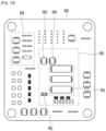
- a region including the compressor control circuit 951 and the temperature sensor 952 and also including the DC-DC converter 953 and the diode 954 is referred to as a heat sink corresponding portion 955, and the heat sink 930 may come into direct or indirect contact with the region corresponding to the heat sink 955.
- an installation place of the heat sink 930 is a place where relatively cool air flows as the outer space of the machine room cover 700, the cooling operation through the heat sink 930 may be performed smoothly. Thus, the cooling of the heat generation parts may be smoothly performed.
- Fig. 11 is a block diagram for explaining control of the vehicle refrigerator.
- the vehicle refrigerator may be divided into a cavity 100, a machine room 200, a door 800, and a control board 950 for controlling the cavity, the machine room, and the door according to control functions.
- the cavity 100 is provided with a temperature sensor 181 for measuring a temperature in the cavity, an evaporation fan 182 included in the evaporation module 400 to cause cold air circulation inside the cavity, and a light source 183 that brightens the inside of the cavity.
- a control unit 961 of the control board 950 Each of the parts is controlled by a control unit 961 of the control board 950.
- a condensation fan 281 that draws an air flow inside the machine room and a compressor 282 that draws a refrigerant flow from the refrigeration system are provided in the machine room 200.
- the condensation fan 281 and the compressor 282 are controlled by the control unit 961.
- a magnet 891 may be installed on the door 800, and a corresponding operation may be performed by the controller 961 when the access of the magnet 891 is detected by the sensor 964.
- a relay switch 966 operates under the control of the control unit 961, and voltage regulators 965 and 967 control an operation of fans 182 and 281.
- An UART port for inputting data may be provided on the control board 950. Necessary data may be stored by the UART port.
- a power switch 963 for interrupting power supplied from a 12-volt power source is disposed on the control board 950.
- the control unit 961 may be provided with a refrigerator control unit and a compressor control unit in a single chip.
- a compressor control circuit for switching the compressor 282 and supplying a high voltage to the compressor 282 is provided in plurality of chips on the board between the compressor 282 and the controller 961.
- the compressor control circuit 951 may operate by a control command of the control unit 961 to supply energy to the compressor 282.
- the compressor 282, the condensing fan 281, and the evaporation fan 2 may operate to correspond to a temperature inside the cavity.
- an intermittent operation may naturally occur depending on an operation state such as a supercooled state. The intermittent operation is sensed by the temperature sensor 181 and then controlled.
- An on/off operation of the compressor 282, the condensing fan 281, and the evaporation fan 2 may not be said to be performed together, and an on/off state may be different depending on a flow of the refrigerant and the current temperature.
- the sensor 964 senses a change in magnetic field due to disengagement or approach of the magnet, which may be determined as opening of the door 800. Thereafter, the compressor 282 may be turned off, or the fans 182 and 281 may be stopped. When the opening of the door 800 is sensed, the evaporation fan 182 may be turned off at all times. This is for preventing cold air from being lost.
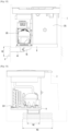
- Fig. 12 is a front view of the vehicle refrigerator.
- the vehicle refrigerator is disposed in the console space 4.
- the air inside the machine room which passes through a previously set path, is directed to the exhaust port 6 through the passage guide 81.
- the passage guide 81 is provided to be recessed in the refrigerator bottom frame, and at least a portion thereof is provided to be inclined in a direction toward the exhaust port 6.
- connection passage 65 may be provided in a path between the passage guide 81 and the exhaust port 6.
- the connection passage 65 is a member for connecting the passage guide 81 provided in the refrigerator bottom frame 8 to an inlet end of the exhaust port 6.
- connection passage 65 a laminar flow flowing through the passage guide 81 may be continuous.
- the air flow may be stably guided.
- the recirculation of the machine room discharge air may be considerably attenuated by making an outlet of the connection passage 81 to be placed at a position adjacent to the inlet end of the exhaust port 6. This leads to a great effect in improving heat efficiency.
- the exhaust port 6 has a height H2 greater than that H1 of the outlet end of the passage guide 81. This is intended to reduce discomfort of the assistant driver by the hot air discharged from the exhaust port 6 and to suppress recirculation of the discharged air. According to this, the air discharged from the passage guide 81 is diffused, and a flow velocity thereof is slowed down so that an effect of preventing direct contact with the assistant driver is obtained.
- Fig. 13 is a left view of the vehicle refrigerator.
- the exhaust port has a width W2 greater than that of the passage guide 81. According to this, the air discharged from the passage guide 81 is diffused, and a flow velocity thereof is slowed down so that an effect of preventing direct contact with the assistant driver is obtained. Also, a smooth exhaust operation may be obtained, and the recirculation of the discharged air may be suppressed.
- the center of the exhaust port When comparing a height of a center of the exhaust port with a height of a discharge end of the passage guide 81, the center of the exhaust port has a relatively low height when comparing centers of the members. This is because the air discharged from the passage guide 81 is directed downward so that natural air flow is maximized.
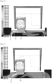
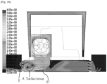
- Figs. 14 to 18 are diagrams of simulations for explaining various structures of the passage guide.
- the passage guide 81 may have an inclined part that is gradually lowered in the left direction to guide the flow.
- the passage guide 81 is provided by a method such as cutting and drawing of a plate-shaped refrigerator bottom frame 8 and has a size and a structure similar to an area of the cut plate.
- the air discharged from the machine room 200 is recirculated to the console space through the spacing part between the refrigerator bottom frame 8 and the console space 4.
- the recirculated air may be reintroduced into the machine room 200 to lead to reduction in efficiency of the refrigeration system.
- the passage guide 81 of this example has the inclined part that is lowered in the left direction to guide the flow and is provided by a method such as cutting and drawing in the plate-like refrigerator bottom frame 8 to provide a size and structure similar to those of the area of the cut plate. Also, a blocking wall 66 extending downward from a lower end of the discharge end of the passage guide is provided.
- the spacing part between the refrigerator bottom frame 8 and the console space 4 is blocked by the blocking wall 66, and the discharged air does not flow therebetween.
- hot air recirculated to the machine room 200 i.e., the inlet side of the condensation module 500, may be removed.
- the blocking wall 66 may be a preferred means for preventing the recirculation of the exhaust air of the machine room.
- the passage guide 81 of this example has the inclined part that is lowered in the left direction to guide the flow and is provided by a method such as cutting and drawing in the plate-like refrigerator bottom frame 8 to provide a size and structure similar to those of the area of the cut plate. Also, the connection passage 65 further extending to the exhaust port 6 of the discharge end of the passage guide 81 is provided.
- connection passage 65 extends to the vicinity of the inlet end of the exhaust port 6 and does not come into contact with the exhaust port 6. This is because the discharged air of the connection passage 65 is directly discharged through the exhaust port 6, thereby preventing a large flow rate from being generated and causing the user to feel uncomfortable. Also, it is possible to prevent the recirculation of the machine room discharge air by such a structure.
- connection passage 65 may have a size greater than that of the inlet side of the connection passage 65.
- connection passage 65 may act as a diffuser by itself.
- the outlet end of the connection passage 65 may be aligned with the size of the exhaust port 6, and the outlet end of the connection passage 65 may come into contact with the inlet end of the exhaust port 6 when the diffuser is employed. In this case, the discomfort of the assistant driver may be eliminated.
- the passage guide 81 of this example does not have the inclined part that is lowered in the left direction and is provided by a method such as cutting and drawing in the plate-like refrigerator bottom frame 8 to provide a size and structure similar to those of the area of the cut plate.
- a turbulence generation inside the flow guide 81 increases, and the turbulence inside the flow guide 81 propagates to the outside. Thus, it is confirmed that the flow reaches the spacing part between the refrigerator bottom frame 8 and the console space 4, and recirculation of the machine room discharge air occurs.
- the recirculation of the machine room discharge air adversely affects the heat exchange performance, the efficiency of the refrigerator deteriorates, and the internal temperature of the cavity becomes worse.
- the passage guide 81 may have an inclined part that is gradually lowered in the left direction to guide the flow. Also, the passage guide 81 is provided by a method such as cutting and drawing in the plate-like refrigerator bottom frame 8 so as to have the size and structure similar to the area of the cut plate. In addition, the passage guide 81 is further downward so as to have a height and an up-and-down width equal to that of the exhaust port 8.
- the turbulence region A is generated in the discharge part of the passage guide 81 due to the size of the excess flow guide and the influence of the turbulence region A is generated between the refrigerator bottom frame 8 and the console space 4 so that the flow reaches the spacing part. As a result, it is seen that recirculation of the discharged air occurs.
- the application of the blocking wall 66 and the connection passage 65 is a preferable means for preventing the recirculation of the machine room discharge air discharged from the discharge end of the passage guide 81.
- Fig. 19 is a view illustrating an internal configuration of a vacuum adiabatic body according to various embodiments.
- a vacuum space part 50 is provided in a third space having a different pressure from first and second spaces, preferably, a vacuum state, thereby reducing adiabatic loss.
- the third space may be provided at a temperature between the temperature of the first space and the temperature of the second space.
- a constituent that resists heat transfer between the first space and the second space may be called a heat resistance unit.
- all various constituents may be applied, or the various constituents may be selectively applied.
- the third space is provided as a space in the vacuum state
- the first and second plate members 10 and 20 receive a force contracting in a direction in which they approach each other due to a force corresponding to a pressure difference between the first and second spaces. Therefore, the vacuum space part 50 may be deformed in a direction in which it is reduced. In this case, adiabatic loss may be caused due to an increase in amount of heat radiation, caused by the contraction of the vacuum space part 50, and an increase in amount of heat conduction, caused by contact between the plate members 10 and 20.
- the vacuum adiabatic body may be fabricated without using the supporting unit 30.
- the porous substance 33 may simultaneously serve as the radiation resistance sheet 32 and the supporting unit 30.
Landscapes
- Engineering & Computer Science (AREA)
- Physics & Mathematics (AREA)
- Thermal Sciences (AREA)
- Mechanical Engineering (AREA)
- Chemical & Material Sciences (AREA)
- Combustion & Propulsion (AREA)
- General Engineering & Computer Science (AREA)
- Transportation (AREA)
- Devices That Are Associated With Refrigeration Equipment (AREA)
- Compressor (AREA)
- Air-Conditioning For Vehicles (AREA)
Description
- The present disclosure relates to a refrigerating or warming apparatus and a vehicle.
- Refrigerators are apparatuses for storing products such as foods received in the refrigerator at a low temperature including sub-zero temperatures. As a result of this action, there is an advantage that user's intake with respect to the products may be improved, or a storage period of the products may be lengthened.
- Refrigerators are classified into indoor refrigerators using a commercial power source or outdoor refrigerator using a portable power source. In addition, in recent years, a refrigerator for a vehicle, which is used after fixedly mounted on the vehicle, is increasing in supply. The refrigerator for the vehicle is more increasing in demand due to an increase in supply of vehicles and an increase in premium-class vehicle.
- A conventional configuration of the refrigerator for the vehicle will be described.
- First, there is an example in which heat in the refrigerator is forcibly discharged to the outside of the refrigerator by using a thermoelement. However, there is a limitation in that a cooling rate is slow due to low thermal efficiency of the thermoelement to deteriorate user's satisfaction.
- For another example, there is an example in which a refrigerant or cold air is drawn from an air conditioning system installed for air-conditioning an entire interior of the vehicle and used as a cooling source for the refrigerator for the vehicle.
- In this example, there is a disadvantage that a separate flow path of air or refrigerant is required to draw the air or refrigerator from the air conditioning system of the vehicle. Also, there is a limitation that low-temperature energy is lost during the movement of the air or refrigerant through the flow path. Also, there is a limitation that a position at which the refrigerator for the vehicle is installed is limited to a position that is adjacent to the air conditioning system of the vehicle due to the above-described limitations.
- For another example, there is an example in which a refrigeration cycle using a refrigerant is applied.
- In this example, since a part constituting the refrigeration cycle is large in size, most of the parts are mounted on a trunk, and only a door of a door of the refrigerator is opened to the inside of the vehicle. In this case, there is a limitation that a position for installing the refrigerator for the vehicle is limited. Also, there is a limitation that the trunk is significantly reduced in volume to reduce an amount of cargo that is capable of being loaded in the trunk.
- Further configurations of a cooling apparatus are known from
US 4545211 A andWO 2011/021798 A2 . -
US 4545211 A describes a cold box for a vehicle which is provided with a pedestal comprising a cooling aggregate and a condenser. A cooling chamber is placed on top of the pedestal on the cooling aggregate. A forced air cooling system is provided for the condenser. Grills for the inlet and exhaust air flow are incorporated in the region of front and/or rear walls of the pedestal. A blower controlled by a drive control of the motor of the refrigeration compressor creates a forced one-directional convection and a cooling effect for the condenser.WO 2011/021798 A2 relates to a refrigerator including a body formed to have a freezing chamber and a refrigerating chamber, a machine room provided on a top of the body to have a front region and a rear region, a vibration isolating member for attenuating vibration in the machine room, and a blocking member for attenuating noise in the machine room. The front region has the compressor mounted thereto, and the rear region has a condenser and the cooling fan mounted thereto. Moreover, the front region has a first guide member for guiding an air flow toward the compressor from the cooling fan, and the rear region has a second guide member for guiding an air flow toward the condenser. The air flow is provided through front holes and side holes in a cover member of the machine room. - Embodiments also provide a refrigerating or warming apparatus to which a driver is directly accessible while using refrigeration cycle, and a vehicle.
- Embodiments also provide a refrigerating or warming apparatus that is capable of increasing a capacity of a refrigerator, and a vehicle.
- Embodiments provide a refrigerating or warming apparatus that is capable of improving energy efficiency, and a vehicle.
- Such a refrigerating or warming apparatus is configured as described in
independent claim 1. In one embodiment, to allow a driver to be directly accessible by using a refrigeration cycle, a refrigerating or warming apparatus includes: a cavity of which at least a portion of a wall is provided as a vacuum adiabatic body; a machine room disposed at a side outside the cavity; a compressor accommodated in the machine room to compress a refrigerator; a first heat exchange module accommodated in the machine room to allow the refrigerant to be heat-exchanged; and a second heat exchange module accommodated in the cavity to allow the refrigerant to be heat-exchanged. - To increase a capacity of a refrigerator and realize high integration of the machine room, the refrigerating or warming apparatus may further include a machine room cover which covers the machine room to separate a passage and in which the internal air flow and the external air flow have directions opposite to each other.
- To improve energy efficiency and heat dissipation performance, the refrigerating or warming apparatus may further include a passage guide for guiding discharge-side air of the internal air flow to the direction opposite to the cavity.
- The refrigerating or warming apparatus may further include a connection passage further provided on a discharge end of the passage guide to suppress recirculation of hot air, thereby more improving the heat dissipation performance.
- Inlet-side air of the external air flow may flow to the cavity to more suppress the recirculation of the hot air.
- To improve energy efficiency and realize high integration of the machine room, the external air flow may have a width that gradually decreases as the air flow proceeds.
- To achieve sufficient heat dissipation performance, the machine room cover may have at least two stepped parts. A controller may be disposed on the stepped part.
- To improve integration, a compressor driving circuit and a refrigerating or warming apparatus control circuit may be provided together in the controller.
- Moreover, a vehicle comprising a refrigerating or warming apparatus with the features of
independent claim 1 is provided. To obtain a vehicle on which a refrigerating or warming apparatus having a quick temperature adjustment performance is mounted, a vehicle is provided which includes: a console; a suction port and an exhaust port, which are provided in left and right sides of the console; a cavity and a machine room, which are horizontally provided in an inner space of the console; a compressor and a first heat exchange module, which are provided in the machine room; and a second heat exchange module accommodated in the cavity. - To secure capacity of a refrigerator and realize high integration, the external air flow outside the machine room cover covering the machine room and the internal air flow inside the machine room cover may have directions opposite to each other.
- To increase energy efficiency and secure sufficient heat dissipation performance, the vehicle may further include a passage guide provided in the refrigerator bottom frame to guide a flow of air discharged to the outside of the machine room to the exhaust port.
- To prevent air discharged from the passage guide from recirculating, the vehicle may further include a connection passage between an inlet end of the exhaust port and a discharge end of the passage guide. The vehicle may further include a blocking wall blocking a space between a bottom of an inner space of the console and the discharge end of the passage guide.
- To increase energy efficiency and secure sufficient heat dissipation performance, the passage guide may be vertically aligned with the compressor.
- In further another embodiment, to safely control the refrigerating or warming apparatus, the refrigerating or warming apparatus includes: a cavity and a machine room, which are horizontally aligned with each other; a compressor accommodated in the machine room; and a machine room cover which covers the machine room to separate a passage and outside which a controller is disposed.
- To realize high integration of the refrigerating or warming apparatus, the controller may include a compressor driving circuit for driving the compressor.
- To secure cooling performance of the controller, air heated by cooling the controller may be introduced into the machine room.
- To secure high integration of the machine room and the refrigerating or warming apparatus together with heat dissipation performance, air through which the controller and air flowing through the machine room may have directions opposite to each other.
- According to the refrigerating or warming apparatus including: a cavity of which at least a portion of the wall is provided as the vacuum adiabatic body; the machine room disposed at a side of the outside of the cavity; the compressor accommodated in the machine room to compressor the refrigerant; the first heat exchange module accommodated in the machine room to allow the refrigerant to be heat-exchanged; and the second heat exchange module accommodated in the cavity to allow the refrigerant to be heat-exchanged, the refrigerating or warming apparatus may be disposed at the position that is close to the driver.
- The refrigerating or warming apparatus further includes the machine room cover which covers the machine room to separate the passage and in which the internal air flow and the external air flow have the directions opposite to each other. Thus, the air flow within the machine room may be accurately separated to reduce the machine room, thereby increasing in capacity of the cavity.
- The passage guide for guiding the discharge-side air of the internal air flow to the direction opposite to the cavity may be provided. Thus, the hot air may not be applied the cavity to reduce the heat load.
- Since the width of the air flow decreases ad the external air flow proceeds, the sufficient space for cooling each of the parts provided inside and outside the machine room and dissipating the heat of the parts may be secured.
- The controller may be disposed on the stepped part of the machine room cover, and the compressor driving circuit for driving the compressor and the refrigerating or warming apparatus driving circuit may be provided together in the controller to more improve the integration of the refrigerating or warming apparatus and the operation reliability of the refrigerating or warming apparatus.
- The vehicle including: the console; the suction port and the exhaust port, which are provided in the left and right sides of the console; the cavity and the machine room, which are horizontally provided in the inner space of the console; the compressor and the first heat exchange module, which are provided in the machine room; and the second heat exchange module accommodated in the cavity may be provided. Thus, the user of the vehicle may quickly provide the accommodation product at the desired temperature condition.
- The external air flow outside the machine room cover covering the machine room and the internal air flow inside the machine room cover may have the directions opposite to each other. Thus, the refrigeration cycle may be sufficiently accommodated in the narrow space.
- The high-temperature air may be prevented from influencing the cavity by the passage guide for guiding the passage of the air discharged to the outside of the machine room toward the exhaust port.
- The passage guide may be vertically aligned with the compressor to quickly discharge the air and realize the high-integration of the machine room.
- The refrigerating or warming apparatus including: the cavity and the machine room, which are horizontally aligned with each other; the compressor accommodated in the machine room; and the machine room cover which covers the machine room to separate the passage and outside which the controller is disposed may be provided. Thus, the controller may be prevented from being broken down in the narrow space to stably drive the refrigerating or warming apparatus.
- The compressor driving circuit for driving the compressor may be provided in the controller to more reduce the inner space of the machine room.
- The air flowing through the controller may be introduced into the machine room to satisfy the heat dissipation conditions of the controller.
- Since the air flowing through the controller and the air flowing through the machine room are provided in opposite directions, the inner and outer spaces of the narrow machine room may be sufficiently utilized to perform the cooling.
-
-
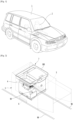
Fig. 1 is a perspective view of a vehicle according to an embodiment. -
Fig. 2 is an enlarged perspective view illustrating a console of the vehicle. -
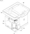
Fig. 3 is a schematic perspective view illustrating the inside of a vehicle refrigerator. -
Fig. 4 is a view for explaining an air flow outside a machine room of the vehicle refrigerator. -
Fig. 5 is a bottom perspective view of a machine room cover. -
Fig. 6 is a view illustrating the inside of the machine room from which the machine room cover is removed. -
Fig. 7 is a front perspective view of the machine room cover. -
Fig. 8 is a perspective view of a controller. -
Fig. 9 is an exploded perspective view of the controller. -
Fig. 10 is a schematic circuit diagram of a control board. -
Fig. 11 is a block diagram for explaining control of the vehicle refrigerator. -
Fig. 12 is a front view of the vehicle refrigerator. -
Fig. 13 is a left view of the vehicle refrigerator. -
Figs. 14 to 18 are diagrams of simulations for explaining various structures of a passage guide. -
Fig. 19 is a view illustrating an internal configuration of a vacuum adiabatic body according to various embodiments. -
Fig. 20 is a view of a conductive resistance sheet and a peripheral portion of the conductive resistance sheet. -
Fig. 21 is a graph illustrating results obtained by observing a time and a pressure in a process of exhausting the inside of the vacuum adiabatic body when a supporting unit is used. -
Fig. 22 is a graph obtained by comparing a vacuum pressure with gas conductivity. - In the following description according to embodiments with reference to the drawings, the same reference numerals are given to different drawings in the case of the same constituents.
- Also, in the description of each drawing, the description will be made with reference to the direction in which the vehicle is viewed from the front of the vehicle, rather than the front viewed by the driver based on the traveling direction of the vehicle. For example, the driver is on the right, and the assistant driver is on the left.
-
Fig. 1 is a perspective view of a vehicle according to an embodiment. - Referring to
Fig. 1 , aseat 2 on which a user is seated is provided in avehicle 1. Theseat 2 may be provided in a pair to be horizontally spaced apart from each other. A console is disposed between theseats 2, and a driver places items that are necessary for driving or components that are necessary for manipulating the vehicle in the console. Front seats on which the driver and the assistant driver are seated may be described as an example of theseats 2. - It should be understood that the vehicle includes various components, which are necessary for driving the vehicle, such as a moving device such as a wheel, a driving device such as an engine, and a steering device such as a steering wheel.
- The refrigerator for the vehicle according to an embodiment may be preferably placed in the console. However, an embodiment of the present disclosure is not limited thereto. For example, the vehicle refrigerator may be installed in various spaces. For example, the vehicle refrigerator may be installed in a space between rear seats, a door, a globe box, and a center fascia. This is one of factors that the vehicle refrigerator according to an embodiment is capable of being installed only when power is supplied, and a minimum space is secured. However, it is an advantage of the embodiment in that it may be installed in the console between the seats, which is limited in space due to limitations in vehicle design.
-
Fig. 2 is an enlarged perspective view illustrating the console of the vehicle. - Referring to
Fig. 2 , aconsole 3 may be provided as a separate part that is made of a material such as a resin. Asteel frame 98 may be further provided below theconsole 3 to maintain strength of the vehicle, and asensor part 99 such as a sensor may be disposed in a spacing part between theconsole 3 and thesteel frame 98. Thesensor part 99 may be a part that is necessary for accurately sensing an external signal and measuring a signal at a position of the driver. For example, an airbag sensor that is directly connected to the life of the driver may be mounted. - The
console 3 may have aconsole space 4 therein, and theconsole space 4 may be covered by aconsole cover 300. Theconsole cover 300 may be fixed to theconsole 3 in a fixed type. Thus, it is difficult that external foreign substances are introduced into the console through theconsole cover 300. Avehicle refrigerator 7 is seated in theconsole space 4. - A
suction port 5 may be provided in a right surface of theconsole 3 to introduce air within the vehicle into theconsole space 4. Thesuction port 5 may face the driver. Anexhaust port 6 may be provided in a left surface of theconsole 3 to exhaust warmed air while the vehicle refrigerator operates from the inside of theconsole space 4. Theexhaust port 6 may face the assistant driver. A grill may be provided in each of thesuction port 5 and theexhaust port 6 to prevent user's hand from being inserted and thereby to provide safety, prevent an object, which falls from an upper side, from being introduced, and allow air to be exhausted to flow downward so as not to be directed to the person. -
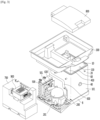
Fig. 3 is a schematic perspective view illustrating the inside of the vehicle refrigerator.
Referring toFig. 3 , thevehicle refrigerator 7 includes arefrigerator bottom frame 8 supporting parts, amachine room 200 provided in a left side of therefrigerator bottom frame 8, and acavity 100 provided in a right side of therefrigerator bottom frame 8. Themachine room 200 may be covered by amachine room cover 700, and an upper side of thecavity 100 may be covered by theconsole cover 300 and adoor 800. - The
machine room cover 700 may not only guide a passage of the cooling air, but also prevent foreign substances from being introduced into themachine room 200. - In more detail, air flows (a first flow) into a spacing part between the
machine room cover 700 and theconsole cover 300 and then flows (a second flow) into themachine room cover 700. Also, the first flow and the second flow are provided in opposite directions. Thus, cooling performance may be maximized in the narrow space. - A
controller 900 may be disposed on themachine room cover 700 to control an overall operation of thevehicle refrigerator 7. Since thecontroller 900 is installed at the above-described position, thevehicle refrigerator 7 may operate without problems in a proper temperature range in a narrow space inside theconsole space 4. - That is to say, the
controller 900 may be cooled by air flowing through a gap between themachine room cover 700 and theconsole cover 300 and separated from an inner space of themachine room 200 by themachine room cover 700. Thus, thecontroller 900 may not be affected by heat within themachine room 200. - The
console cover 300 may not only cover an opened upper portion of theconsole space 4, but also cover an upper end edge of thecavity 100. Adoor 800 may be further installed on theconsole cover 300 to allow the user to cover an opening through which products are accessible to thecavity 100. - The
door 800 may be opened by using rear portions of theconsole cover 300 and thecavity 100 as hinge points. Here, the opening of theconsole cover 300, thedoor 800, and thecavity 100 may be performed by conveniently manipulating thedoor 800 by the user because theconsole cover 300, thedoor 800, and thecavity 100 are horizontally disposed when viewed from the user and also disposed at a rear side of the console. - A
condensation module 500, adryer 630, and acompressor 201 may be successively installed in themachine room 200 in a flow direction of the cooling air. Arefrigerant conduit 600 for allowing the refrigerant to smoothly flow is provided in themachine room 200. A portion of therefrigerant conduit 600 may extend to the inside of thecavity 100 to supply the refrigerant. Therefrigerant conduit 600 may extend to the outside of thecavity 100 through the upper opening through which the products are accessible to thecavity 100. - The
cavity 100 has an opened top surface and five surfaces that are covered by a vacuumadiabatic body 101. Each of surfaces of thecavity 100 may be thermally insulated by an individual vacuum adiabatic body or at least one or more vacuum adiabatic bodies communicating with each other. Thecavity 100 may be provided by the vacuumadiabatic body 101. Also, thecavity 100 through which the products is accessible through one surface opened by the vacuumadiabatic body 101 may be provided. - The vacuum
adiabatic body 101 may include afirst plate member 10 providing a boundary of a low-temperature inner space of thecavity 100, asecond plate member 20 providing a boundary of a high-temperature outer space, and aconductive resistance sheet 60 blocking heat transfer between theplate members adiabatic body 101 has a thin adiabatic thickness to maximally obtain adiabatic efficiency, thecavity 100 having large capacity may be realized. - An exhaust and getter port for the exhaust of the inner space of the vacuum
adiabatic body 101 and for installing a getter that maintains the vacuum state may be provided on one surface. The exhaust andgetter port 40 may provide the exhaust and getter together to more contribute to miniaturization of thevehicle refrigerator 7. - Details of the vacuum
adiabatic body 101 will be described later. - An
evaporation module 400 may be installed in thecavity 100 provided as the vacuumadiabatic body 101. Theevaporation module 400 may forcibly blow the evaporation heat introduced into thecavity 100 through therefrigerant conduit 600 into thecavity 100. The evaporation module may be disposed at a rear side within thecavity 100. -
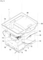
Fig. 4 is a view for explaining an air flow outside a machine room of the vehicle refrigerator. - Referring to
Fig. 4 , air introduced into thesuction port 5 moves to a left side of the vehicle refrigerator through a space between the vacuumadiabatic body 101 defining a front wall of thecavity 100 and an inner front surface of theconsole space 4. Since a heating source is not provided at a right side of the vehicle refrigerator, the suction air may be maintained at its original temperature. - The air moving to the left side of the vehicle refrigerator may be changed in direction to a rear side to move along a top surface of the
machine room 700 outside themachine room 200. - To smoothly guide the air flow, the
machine room cover 700 may have a height that gradually increases backward from thefront surface 710. Also, to provide a region in which thecontroller 900 is disposed, and prevent the parts within the machine room from interfering in position with each other, a stepped part may be disposed on the top surface of themachine room 700. - In detail, a
first step portion 732, a second steppedpart 733, and a third steppedpart 735 may be successively provided backward from the front surface. Acontroller placing part 734 having the same height as the third stepped part is disposed on the second steppedpart 733. According to this structure, thecontroller 900 may be disposed in parallel to the third steppedpart 735 and thecontroller placing part 734. - The air moving along the top surface of the
machine room cover 700 may cool thecontroller 900 on the flow path. Although the air may be slightly heated while cooling the controller, a degree of the temperature rise may be insignificant. - The air moving up to the rear side of the
machine room cover 700 flows downward. A large cover suction hole (seereference numeral 751 ofFig. 5 ) that is opened in the rear surface of themachine room cover 700 may be provided. For this, a predetermined space may be provided between the rear surface of themachine room cover 700 and the rear surface of theconsole space 4. - The flow within the
machine room 200 will be described with reference to the bottom perspective view of the machine room cover inFig. 5 and the view of the machine room, from which the machine room cover is removed, inFig. 6 . - Referring to
Figs. 4 to 6 , thecover suction hole 751 is provided in therear surface 750 of themachine room cover 700. Air may be introduced forward from the rear surface of the machine room through thecover suction hole 751. - The air introduced through the
cover suction hole 751 may pass through thecondensation module 500 to perform a condensation action of the refrigerant and thereby to be heated. Then, heat exchange action with respect to the driver and the expansion valve is performed. Thereafter, the refrigerant cools thecompressor 201 and is discharged to the bottom surface of themachine room 200. - The refrigerant discharged from the
machine room 200 is discharged to a left side through a hole defined in the machineroom bottom frame 210 provided below the compressor and thepassage guide 81 of therefrigerator bottom frame 8. Thepassage guide 81 is aligned with theexhaust port 6 of the console, and the heated air is discharged to the assistant driver. Here, to prevent inconvenience to the assistant driver, a grill of theexhaust port 6 is provided to be inclined downward, and hot air may be discharged to the under seat of the assistant driver. - The air flow will be described again with respect to a flow direction.
- First, the air is generally suctioned to the driver and generally discharged to the assistant driver, i.e., the left direction.
- In detail, there are a path through which the air suctioned from the right side through the
suction portion 5 moves in the right direction from thecavity 100 to the machine room, a path through which the moves from a region of machine room to the outside of the machine room, a path through which the air moves downward from an upper side of the machine room, a path through which the air moves forward from the inside of the machine room, a path through which the air moves downward from a front portion of the machine room, and a path through which the air moves from the machine room to the left side and then exhausted through theexhaust port 6. - The above-described paths are configurations that satisfy the spatial integration for perfectly performing the operation of the vehicle refrigerator while mounting the refrigerant system in the narrow space.
- Power for drawing the air flow may be generated by the
condensation fan 501 provided in thecondensation module 500. Thus, in view of the flow path of air, the air to be suctioned into thecondensation fan 501 may be disposed outside the machine room. The discharged air may be blown to the inside of the machine room with respect to thecondensation fan 501. - The air discharged from the
condensation fan 501 may be discharged only through thepassage guide 81. - The reason is for preventing the hot air discharged to the outside of the
machine room cover 700 does not recirculate to the suction-side of thecondensation fan 501. For this, the inside of the machine room surrounded by themachine room cover 700 may not communicate with the other sides except for thepassage guide 81. - As may be seen, the air discharged from the inside of the
machine room 200 may not be discharged to the outside of theconsole space 4, but flow again into the inside of themachine room 200 to have great influence on the efficiency reduction of the refrigeration system. - In order to prevent this influence, the air in the machine room may be discharged only through the
flow guide 81 and not discharged to the other parts, and the air discharged through theflow guide 81 may be smoothly discharged to the exhaust port. If the air discharged through the passage guide is stagnated in theconsole space 4 without being discharged through theexhaust port 6, some of the air may eventually flow into themachine room 200. This causes severe cooling efficiency deterioration. - When a fan rate of the
condensation fan 501 increases, efficiency of the system may be obtained even though the recirculation air exists. However, when a rotation rate of the condensation fan increases, a loud noise is generated, and the noise is inconvenient to the driver. The vehicle refrigerator according to an embodiment is adjacent to the driver since the vehicle refrigerator is installed in the console. Therefore, the noise problem becomes more series. Due to such a background, the maximum rotation rate of the condensingfan 501 is preferably limited to about 2,000 rpm. -
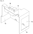
Fig. 7 is a front perspective view of the machine room cover. - Referring to
Fig. 7 , themachine room cover 700 has afront surface 710, atop surface 730, and aleft surface 700 as described above. A hole may be defined in a rear surface to allow air to be introduced. - The inner space of the
machine room 100 may be defined by themachine room cover 700, and the right and bottom surfaces of themachine room cover 700 may be provided as empty spaces. The left surface of themachine room 100 becomes the right surface of the cavity, and the bottom surface of themachine room 100 may be the bottom of the machine room. According to the above-described constituents, the inner space of the machine room may be defined. - The
upper surface 730 is provided with steppedparts - A
controller placing part 734 protruding upward from a top surface of the second steppedpart 733 is provided. A top surface of thecontroller placing part 734 and a bottom surface of the third stepped part 375 may have the same height. Thus, thecontroller 900 may be disposed in a horizontal state. - A
recess part 733 having the same height as the top surface of the second steppedpart 733 may be defined between thecontroller placing part 734 and the bottom surface of the third steppedpart 735. Therecess part 733 may provide a space through which air below thecontroller 900 flows, and external air may be introduced into or discharged from the space. Thus, cooling of thecontroller 900 may be performed through the upper portion and the lower portion thereof. Thus, the cooling of thecontroller 900 may be more smoothly performed, and an operation temperature of the controller may be satisfied in the narrow space within theconsole 3. - The machine room cover may be coupled to an outer wall of the vacuum
adiabatic body 101 defining thecavity 100. For this, acavity coupling part 742 may be disposed at the right side of themachine room cover 700, and themachine room cover 700 and thecavity 100 may be provided as one body. - Since the
machine room cover 700 completely seals a left surface of the cavity, the air within the machine room may not leak to the outside. Thus, the recirculation of the air may be prevented to improve the cooling efficiency. - The
controller 900 is installed in the inner spaces between the second steppedpart 733 and the third steppedpart 735. Thecontroller 900 is coupled and fixed to themachine room cover 700, andcontroller coupling parts - A through-
hole 741 guiding therefrigerant conduit 600 that guides the refrigerant into the cavity through the upper opening of the cavity is defined in the right side of themachine room cover 700. Therefrigerant conduit 600 passing through the through-hole 741 may correspond to the regeneration conduit adiabatic member. The regeneration conduit adiabatic member may be a member for thermally insulating a regeneration conduit system that exchanges heat of the first refrigerant conduit, which is introduced into theevaporation module 400, and heat of the second refrigerant conduit, which is discharged from the evaporation module. - The regeneration conduit system may constitute a portion of the
refrigerant conduit 600. -
Fig. 8 is a perspective view of the controller, andFig. 9 is an exploded perspective view of the controller. - Referring to
Figs. 8 and9 , the controller includes alower case 910 and anupper cover 920, which provide an inner space. -
Cover coupling parts control coupling parts machine room cover 700, may be provided in thelower case 910 and be horizontally seated on the top surface of themachine room cover 700. Aconnection terminal 943 may be disposed on one side of thelower case 910 to perform electrical connection of a power source and a sensor. - All electrical connection terminals provided in the vehicle refrigerator may use a double lock connection terminals so as not to release the coupling due to the driving of the vehicle and vibration due to the driving.
- A
control board 950 is disposed in an inner space defined by thelower case 910 and theupper cover 920. - A plurality of heat generation sources are mounted on the
control board 950. Among them, the compressor driving circuit for driving thecompressor 201 includes a switching circuit, and a large amount of heat is generated because relatively large current flows through the compressor. - The compressor driving circuit is generally coupled to a side surface of the compressor. However, in the case of the embodiment, since the inner space of the machine room is narrow as the vehicle refrigerator, and the position of the compressor is located just before the discharge of the machine room, the temperature of the air flowing is high. Thus, it is inappropriate to install the compressor driving circuit in a space close to the compressor.
- As a solution to this problem, if the compressor driving circuit is provided together with the
control board 950 that controls the whole of the vehicle refrigerator, the space of the vehicle refrigerator may be more compact. However, it is preferable that a heat dissipation structure having high cooling efficiency is provided because a large amount of heat more increases by mounting a plurality of parts on thenarrow control board 950, which may affect the operation of the parts. - To solve this problem, a
heat sink 930 is provided which comes into contact with a heat generation portion of thecontrol board 950 to promote the heat radiation of thecontrol board 950. Acover hole 921 that is opened to a top surface is provided in theupper cover 920. Theheat sink 930 is exposed to the outside through thecover hole 921. - The exposed heat sink is cooled by the air passing through the spacing part between the
machine room cover 700 and theconsole cover 300. In the spacing part between themachine room cover 700 and theconsole cover 300, relatively cool air in which the air introduced into theconsole space 4 does not cool other parts, flows. Therefore, the cooling action of theheat sink 930 may be smoothly performed. Moreover, thecontrol board 950 may be smoothly cooled to improve operational reliability. - A configuration of the
controller 900 will be described in more detail. -
Fig. 10 is a schematic circuit diagram of the control board. - Referring to
Fig. 10 , thecontrol board 950 includes arefrigerator control circuit 956 for controlling an operation of the vehicle refrigerator and acompressor control circuit 951 for controlling an operation of thecompressor 201. - The
refrigerator control circuit 956 may perform functions such as door opening/closing, a fan operation, data storage, state determination, and a command. Thecompressor control circuit 951 is configured to control rotation of a motor of the compressor and has a high heat generation value due to execution of the switching operation and supply of the driving current. - High-temperature heat generated in the
compressor control circuit 951 affects other circuits of thecontrol board 950 and causes a risk of fire. Thus, atemperature sensor 952 is provided in the vicinity of thecompressor control circuit 951 to stop thecompressor 201 when thetemperature sensor 952 senses a temperature equal to or higher than a threshold value. Therefore, it is important that thetemperature sensor 952 should not rise above the threshold value. - Another circuit part having a high heat generation value in the control board is a DC-
DC converter 953 and adiode 954 for boosting a voltage from about 12 volts to about 40 volts. Although these part are not the same as thecompressor control circuit 951, the parts act as large factors of the temperature rise, and if the parts do not operate normally, the parts may lead to malfunction of the vehicle refrigerator. - A region including the
compressor control circuit 951 and thetemperature sensor 952 and also including the DC-DC converter 953 and thediode 954 is referred to as a heatsink corresponding portion 955, and theheat sink 930 may come into direct or indirect contact with the region corresponding to theheat sink 955. - As described above, since an installation place of the
heat sink 930 is a place where relatively cool air flows as the outer space of themachine room cover 700, the cooling operation through theheat sink 930 may be performed smoothly. Thus, the cooling of the heat generation parts may be smoothly performed. -
Fig. 11 is a block diagram for explaining control of the vehicle refrigerator. - Referring to
Fig. 11 , the vehicle refrigerator may be divided into acavity 100, amachine room 200, adoor 800, and acontrol board 950 for controlling the cavity, the machine room, and the door according to control functions. - The
cavity 100 is provided with atemperature sensor 181 for measuring a temperature in the cavity, anevaporation fan 182 included in theevaporation module 400 to cause cold air circulation inside the cavity, and alight source 183 that brightens the inside of the cavity. Each of the parts is controlled by acontrol unit 961 of thecontrol board 950. - A
condensation fan 281 that draws an air flow inside the machine room and acompressor 282 that draws a refrigerant flow from the refrigeration system are provided in themachine room 200. Thecondensation fan 281 and thecompressor 282 are controlled by thecontrol unit 961. - A
magnet 891 may be installed on thedoor 800, and a corresponding operation may be performed by thecontroller 961 when the access of themagnet 891 is detected by thesensor 964. - A
relay switch 966 operates under the control of thecontrol unit 961, andvoltage regulators fans - An UART port for inputting data may be provided on the
control board 950. Necessary data may be stored by the UART port. - A
power switch 963 for interrupting power supplied from a 12-volt power source is disposed on thecontrol board 950. - The
control unit 961 may be provided with a refrigerator control unit and a compressor control unit in a single chip. - When the
control unit 961 is interpreted as a single physical chip, a compressor control circuit for switching thecompressor 282 and supplying a high voltage to thecompressor 282 is provided in plurality of chips on the board between thecompressor 282 and thecontroller 961. Thecompressor control circuit 951 may operate by a control command of thecontrol unit 961 to supply energy to thecompressor 282. - An operation of each part will be described sequentially.
- When the vehicle refrigerator normally operates, i.e., in a state I which the door is not opened, the
compressor 282, the condensingfan 281, and theevaporation fan 2 may operate to correspond to a temperature inside the cavity. Of course, an intermittent operation may naturally occur depending on an operation state such as a supercooled state. The intermittent operation is sensed by thetemperature sensor 181 and then controlled. An on/off operation of thecompressor 282, the condensingfan 281, and theevaporation fan 2 may not be said to be performed together, and an on/off state may be different depending on a flow of the refrigerant and the current temperature. - When the
door 800 is opened during the operation of the vehicle refrigerator, thesensor 964 senses a change in magnetic field due to disengagement or approach of the magnet, which may be determined as opening of thedoor 800. Thereafter, thecompressor 282 may be turned off, or thefans door 800 is sensed, theevaporation fan 182 may be turned off at all times. This is for preventing cold air from being lost. - Hereinafter, a detailed description will be given of a passage of air discharged through the passage guide and a method for suppressing the recirculation of machine room discharge air.
-
Fig. 12 is a front view of the vehicle refrigerator. - Referring to
Fig. 12 , the vehicle refrigerator is disposed in theconsole space 4. The air inside the machine room, which passes through a previously set path, is directed to theexhaust port 6 through thepassage guide 81. - The
passage guide 81 is provided to be recessed in the refrigerator bottom frame, and at least a portion thereof is provided to be inclined in a direction toward theexhaust port 6. - A
connection passage 65 may be provided in a path between thepassage guide 81 and theexhaust port 6. Theconnection passage 65 is a member for connecting thepassage guide 81 provided in therefrigerator bottom frame 8 to an inlet end of theexhaust port 6. - According to the
connection passage 65, a laminar flow flowing through thepassage guide 81 may be continuous. Thus, the air flow may be stably guided. However, it is unnecessary to ensure that theconnection passage 81 comes into contact with the inlet end of theexhaust port 6. The recirculation of the machine room discharge air may be considerably attenuated by making an outlet of theconnection passage 81 to be placed at a position adjacent to the inlet end of theexhaust port 6. This leads to a great effect in improving heat efficiency. - The
exhaust port 6 has a height H2 greater than that H1 of the outlet end of thepassage guide 81. This is intended to reduce discomfort of the assistant driver by the hot air discharged from theexhaust port 6 and to suppress recirculation of the discharged air. According to this, the air discharged from thepassage guide 81 is diffused, and a flow velocity thereof is slowed down so that an effect of preventing direct contact with the assistant driver is obtained. -
Fig. 13 is a left view of the vehicle refrigerator. - Referring to
Fig. 13 , the exhaust port has a width W2 greater than that of thepassage guide 81. According to this, the air discharged from thepassage guide 81 is diffused, and a flow velocity thereof is slowed down so that an effect of preventing direct contact with the assistant driver is obtained. Also, a smooth exhaust operation may be obtained, and the recirculation of the discharged air may be suppressed. - When comparing a height of a center of the exhaust port with a height of a discharge end of the
passage guide 81, the center of the exhaust port has a relatively low height when comparing centers of the members. This is because the air discharged from thepassage guide 81 is directed downward so that natural air flow is maximized. -
Figs. 14 to 18 are diagrams of simulations for explaining various structures of the passage guide. - Referring to
Fig. 14 , thepassage guide 81 according to this embodiment may have an inclined part that is gradually lowered in the left direction to guide the flow. Thepassage guide 81 is provided by a method such as cutting and drawing of a plate-shaped refrigeratorbottom frame 8 and has a size and a structure similar to an area of the cut plate. - In this embodiment, it is seen that the air discharged from the
machine room 200 is recirculated to the console space through the spacing part between therefrigerator bottom frame 8 and theconsole space 4. The recirculated air may be reintroduced into themachine room 200 to lead to reduction in efficiency of the refrigeration system. - In drawing, a deep blue is a portion without flow, and the thicker the red, the faster the flow. This also applies to other drawings.
- Referring to
Fig. 15 , thepassage guide 81 of this example has the inclined part that is lowered in the left direction to guide the flow and is provided by a method such as cutting and drawing in the plate-like refrigeratorbottom frame 8 to provide a size and structure similar to those of the area of the cut plate. Also, a blockingwall 66 extending downward from a lower end of the discharge end of the passage guide is provided. - The spacing part between the
refrigerator bottom frame 8 and theconsole space 4 is blocked by the blockingwall 66, and the discharged air does not flow therebetween. Thus, hot air recirculated to themachine room 200, i.e., the inlet side of thecondensation module 500, may be removed. - The blocking
wall 66 may be a preferred means for preventing the recirculation of the exhaust air of the machine room. - Referring to
Fig. 16 , thepassage guide 81 of this example has the inclined part that is lowered in the left direction to guide the flow and is provided by a method such as cutting and drawing in the plate-like refrigeratorbottom frame 8 to provide a size and structure similar to those of the area of the cut plate. Also, theconnection passage 65 further extending to theexhaust port 6 of the discharge end of thepassage guide 81 is provided. - The
connection passage 65 extends to the vicinity of the inlet end of theexhaust port 6 and does not come into contact with theexhaust port 6. This is because the discharged air of theconnection passage 65 is directly discharged through theexhaust port 6, thereby preventing a large flow rate from being generated and causing the user to feel uncomfortable. Also, it is possible to prevent the recirculation of the machine room discharge air by such a structure. - The outlet side of the
connection passage 65 may have a size greater than that of the inlet side of theconnection passage 65. In this case, theconnection passage 65 may act as a diffuser by itself. The outlet end of theconnection passage 65 may be aligned with the size of theexhaust port 6, and the outlet end of theconnection passage 65 may come into contact with the inlet end of theexhaust port 6 when the diffuser is employed. In this case, the discomfort of the assistant driver may be eliminated. - Referring to
Fig. 17 , thepassage guide 81 of this example does not have the inclined part that is lowered in the left direction and is provided by a method such as cutting and drawing in the plate-like refrigeratorbottom frame 8 to provide a size and structure similar to those of the area of the cut plate. - In this embodiment, a turbulence generation inside the
flow guide 81 increases, and the turbulence inside theflow guide 81 propagates to the outside. Thus, it is confirmed that the flow reaches the spacing part between therefrigerator bottom frame 8 and theconsole space 4, and recirculation of the machine room discharge air occurs. - As described above, the recirculation of the machine room discharge air adversely affects the heat exchange performance, the efficiency of the refrigerator deteriorates, and the internal temperature of the cavity becomes worse.
- Referring to
Fig. 18 , thepassage guide 81 according to this embodiment may have an inclined part that is gradually lowered in the left direction to guide the flow. Also, thepassage guide 81 is provided by a method such as cutting and drawing in the plate-like refrigeratorbottom frame 8 so as to have the size and structure similar to the area of the cut plate. In addition, thepassage guide 81 is further downward so as to have a height and an up-and-down width equal to that of theexhaust port 8. - The turbulence region A is generated in the discharge part of the
passage guide 81 due to the size of the excess flow guide and the influence of the turbulence region A is generated between therefrigerator bottom frame 8 and theconsole space 4 so that the flow reaches the spacing part. As a result, it is seen that recirculation of the discharged air occurs. - As a result of the above experiment, it was confirmed that the application of the blocking
wall 66 and theconnection passage 65 is a preferable means for preventing the recirculation of the machine room discharge air discharged from the discharge end of thepassage guide 81. - The structure and action of the vacuum adiabatic body will be described in more detail.
-
Fig. 19 is a view illustrating an internal configuration of a vacuum adiabatic body according to various embodiments. - First, referring to
Fig. 19a , avacuum space part 50 is provided in a third space having a different pressure from first and second spaces, preferably, a vacuum state, thereby reducing adiabatic loss. The third space may be provided at a temperature between the temperature of the first space and the temperature of the second space. - A constituent that resists heat transfer between the first space and the second space may be called a heat resistance unit. Hereinafter, all various constituents may be applied, or the various constituents may be selectively applied.
- The third space is provided as a space in the vacuum state Thus, the first and
second plate members vacuum space part 50 may be deformed in a direction in which it is reduced. In this case, adiabatic loss may be caused due to an increase in amount of heat radiation, caused by the contraction of thevacuum space part 50, and an increase in amount of heat conduction, caused by contact between theplate members - A supporting
unit 30 may be provided to reduce the deformation of thevacuum space part 50. The supportingunit 30 includesbars 31. Thebars 31 may extend in a direction substantially vertical to the first andsecond plate members second plate members support plate 35 may be additionally provided to at least one end of thebar 31. Thesupport plate 35 connects at least twobars 31 to each other, and may extend in a direction horizontal to the first andsecond plate members - The
support plate 35 may be provided in a plate shape, or may be provided in a lattice shape such that its area contacting the first orsecond plate member bars 31 and thesupport plate 35 are fixed to each other at at least one portion, to be inserted together between the first andsecond plate members support plate 35 contacts at least one of the first andsecond plate members second plate members bars 31, a total sectional area of thesupport plate 35 is provided to be greater than that of thebars 31, so that heat transferred through thebars 31 may be diffused through thesupport plate 35. - A material of the supporting
unit 30 may include a resin selected from the group consisting of PC, glass fiber PC, low outgassing PC, PPS, and LCP so as to obtain high compressive strength, low outgassing and water absorption, low thermal conductivity, high compressive strength at high temperature, and excellent machinability. - A
radiation resistance sheet 32 for reducing heat radiation between the first andsecond plate members vacuum space part 50 will be described. The first andsecond plate members unit 30 made of the resin has a lower emissivity than the plate members, and is not entirely provided to inner surfaces of the first andsecond plate members unit 30 does not have great influence on radiation heat. Therefore, theradiation resistance sheet 32 may be provided in a plate shape over a majority of the area of thevacuum space part 50 so as to concentrate on reduction of radiation heat transferred between the first andsecond plate members - A product having a low emissivity may be preferably used as the material of the
radiation resistance sheet 32. In an embodiment, an aluminum foil having an emissivity of 0.02 may be used as theradiation resistance sheet 32. Also, at least one sheet ofradiation resistance sheet 32 may be provided at a certain distance so as not to contact each other. At least one radiation resistance sheet may be provided in a state in which it contacts the inner surface of the first orsecond plate member vacuum space part 50 has a low height, one sheet of radiation resistance sheet may be inserted. In case of thevehicle refrigerator 7, one sheet of radiation resistance sheet may be inserted so that the vacuumadiabatic body 101 has a thin thickness, and the inner capacity of thecavity 100 is secured. - Referring to
Fig. 19b , the distance between the plate members is maintained by the supportingunit 30, and aporous substance 33 may be filled in thevacuum space part 50. Theporous substance 33 may have a higher emissivity than the stainless material of the first andsecond plate members porous substance 33 is filled in thevacuum space part 50, theporous substance 33 has a high efficiency for resisting the radiation heat transfer. - In this embodiment, the vacuum adiabatic body may be fabricated without using the
radiation resistance sheet 32. - Referring to
Fig. 19c , the supportingunit 30 maintaining thevacuum space part 50 is not provided. Instead of the supportingunit 30, theporous substance 33 is provided in a state in which it is surrounded by a film 34. In this case, theporous substance 33 may be provided in a state in which it is compressed so as to maintain the gap of thevacuum space part 50. The film 34 is made of, for example, a PE material, and may be provided in a state in which holes are formed therein. - In this embodiment, the vacuum adiabatic body may be fabricated without using the supporting
unit 30. In other words, theporous substance 33 may simultaneously serve as theradiation resistance sheet 32 and the supportingunit 30. -
Fig. 20 is a view of a conductive resistance sheet and a peripheral portion of the conductive resistance sheet. - Referring to
Fig. 20a , the first andsecond plate members conductive resistance sheet 60 is provided to prevent heat conduction between two different kinds of plate members. - The
conductive resistance sheet 60 may be provided with sealingparts 61 at which both ends of theconductive resistance sheet 60 are sealed to defining at least one portion of the wall for the third space and maintain the vacuum state. Theconductive resistance sheet 60 may be provided as a thin foil in unit of micrometer so as to reduce the amount of heat conducted along the wall for the third space. The sealingparts 61 may be provided as welding parts. That is, theconductive resistance sheet 60 and theplate members conductive resistance sheet 60 and theplate members conductive resistance sheet 60 and theplate members parts 61 are not limited to the welding parts, and may be provided through a process such as cocking. Theconductive resistance sheet 60 may be provided in a curved shape. Thus, a heat conduction distance of theconductive resistance sheet 60 is provided longer than the linear distance of each plate member, so that the amount of heat conduction may be further reduced. - A change in temperature occurs along the
conductive resistance sheet 60. Therefore, in order to block heat transfer to the exterior of theconductive resistance sheet 60, a shieldingpart 62 may be provided at the exterior of theconductive resistance sheet 60 such that an adiabatic action occurs. In other words, in thevehicle refrigerator 7, thesecond plate member 20 has a high temperature and thefirst plate member 10 has a low temperature. In addition, heat conduction from high temperature to low temperature occurs in theconductive resistance sheet 60, and hence the temperature of theconductive resistance sheet 60 is suddenly changed. Therefore, when theconductive resistance sheet 60 is opened to the exterior thereof, heat transfer through the opened place may seriously occur. - In order to reduce heat loss, the shielding
part 62 is provided at the exterior of theconductive resistance sheet 60. For example, when theconductive resistance sheet 60 is exposed to any one of the low-temperature space and the high-temperature space, theconductive resistance sheet 60 does not serve as a conductive resistor as well as the exposed portion thereof, which is not preferable. - The shielding
part 62 may be provided as a porous substance contacting an outer surface of theconductive resistance sheet 60, may be provided as an adiabatic structure, e.g., a separate gasket, which is placed at the exterior of theconductive resistance sheet 60, or may be provided as theconsole cover 300 disposed at a position facing theconductive resistance sheet 60. - A heat transfer path between the first and
second plate members surface conduction heat ① conducted along a surface of the vacuum adiabatic body, more specifically, theconductive resistance sheet 60,supporter conduction heat ② conducted along the supportingunit 30 provided inside the vacuum adiabatic body,gas conduction heat ③ conducted through an internal gas in the vacuum space part, and radiation transfer heat④ transferred through the vacuum space part. - The transfer heat may be changed depending on various depending on various design dimensions. For example, the supporting unit may be changed such that the first and
second plate members - By performing a relative analysis on heat transfer amounts of the vacuum adiabatic body of the embodiment, a heat transfer amount by the
gas conduction heat ③ may become smallest. For example, the heat transfer amount by thegas conduction heat ③ may be controlled to be equal to or smaller than 4% of the total heat transfer amount. A heat transfer amount by solid conduction heat defined as a sum of thesurface conduction heat ① and thesupporter conduction heat ② is largest. For example, the heat transfer amount by the solid conduction heat may reach 75% of the total heat transfer amount. A heat transfer amount by theradiation transfer heat ④ is smaller than the heat transfer amount by the solid conduction heat but larger than the heat transfer amount of thegas conduction heat ③. For example, the heat transfer amount by theradiation transfer heat ④ may occupy about 20% of the total heat transfer amount. - According to such a heat transfer distribution, effective heat transfer coefficients (eK: effective K) (W/mK) of the
surface conduction heat ①, thesupporter conduction heat ②, thegas conduction heat ③, and theradiation transfer heat ④ may have an order of MathFigure 1 .
[MathFigure 1 ] Here, the effective heat transfer coefficient (eK) is a value that may be measured using a shape and temperature differences of a target product. The effective heat transfer coefficient (eK) is a value that may be obtained by measuring a total heat transfer amount eK solid conduction heat > eK radiation transfer heat > eK gas conduction heat and a temperature at least one portion at which heat is transferred. For example, a calorific value (W) is measured using a heating source that may be quantitatively measured in the refrigerator, a temperature distribution (K) of the door is measured using heats respectively transferred through a main body and an edge of the door of the refrigerator, and a path through which heat is transferred is calculated as a conversion value (m), thereby evaluating an effective heat transfer coefficient. - The effective heat transfer coefficient (eK) of the entire vacuum adiabatic body is a value given by k=QL/A△T. Here, Q denotes a calorific value (W) and may be obtained using a calorific value of a heater. A denotes a sectional area (m2) of the vacuum adiabatic body, L denotes a thickness (m) of the vacuum adiabatic body, and △T denotes a temperature difference.
- For the surface conduction heat, a conductive calorific value may be obtained through a temperature difference (△T) between an entrance and an exit of the
conductive resistance sheet 60, a sectional area (A) of the conductive resistance sheet, a length (L) of the conductive resistance sheet, and a thermal conductivity (k) of the conductive resistance sheet (the thermal conductivity of the conductive resistance sheet is a material property of a material and may be obtained in advance). For the supporter conduction heat, a conductive calorific value may be obtained through a temperature difference (△T) between an entrance and an exit of the supportingunit 30, a sectional area (A) of the supporting unit, a length (L) of the supporting unit, and a thermal conductivity (k) of the supporting unit. Here, the thermal conductivity of the supporting unit is a material property of a material and may be obtained in advance. The sum of thegas conduction heat ③, and theradiation transfer heat ④ may be obtained by subtracting the surface conduction heat and the supporter conduction heat from the heat transfer amount of the entire vacuum adiabatic body. A ratio of thegas conduction heat ③, and theradiation transfer heat ④ may be obtained by evaluating radiation transfer heat when no gas conduction heat exists by remarkably lowering a vacuum degree of thevacuum space part 50. - When a porous substance is provided inside the
vacuum space part 50, poroussubstance conduction heat ⑤ may be a sum of thesupporter conduction heat ② and theradiation transfer heat ④. The poroussubstance conduction heat ⑤ may be changed depending on various variables including a kind, an amount, and the like of the porous substance. - In the second plate member, a temperature difference between an average temperature of the second plate and a temperature at a point at which a heat transfer path passing through the
conductive resistance sheet 60 meets the second plate may be largest. For example, when the second space is a region hotter than the first space, the temperature at the point at which the heat transfer path passing through the conductive resistance sheet meets the second plate member becomes lowest. Similarly, when the second space is a region colder than the first space, the temperature at the point at which the heat transfer path passing through the conductive resistance sheet meets the second plate member becomes highest. - This means that the amount of heat transferred through other points except the surface conduction heat passing through the conductive resistance sheet should be controlled, and the entire heat transfer amount satisfying the vacuum adiabatic body may be achieved only when the surface conduction heat occupies the largest heat transfer amount. To this end, a temperature variation of the conductive resistance sheet may be controlled to be larger than that of the plate member.
- Physical characteristics of the parts constituting the vacuum adiabatic body will be described. In the vacuum adiabatic body, a force by vacuum pressure is applied to all of the parts. Therefore, a material having strength (N/m2) of a certain level may be used.
- Referring to
Fig. 20b , this configuration is the same as that ofFig. 20a except that portions at which thefirst plate member 10, thesecond plate member 20 are coupled to theconductive resistance sheet 60. Thus, the same part omits the description and only the characteristic changes are described in detail. - Ends of the
plate members flange part 65. Awelding part 61 may be disposed on a top surface of theflange part 65 to couple theconductive resistance sheet 60 to theflange part 65. In this embodiment, the worker may perform welding while facing only any one surface. Thus, since it is unnecessary to perform two processes, the process may be convenient. - It is more preferable to apply the case in which welding of the inside and the outside are difficult as illustrated in
Fig. 20a because a space of thevacuum space part 50 is narrow like thevehicle refrigerator 7. -
Fig. 21 is a graph illustrating results obtained by observing a time and a pressure in a process of exhausting the inside of the vacuum adiabatic body when a supporting unit is used. - Referring to
Fig. 21 , in order to create thevacuum space part 50 to be in the vacuum state, a gas in thevacuum space part 50 is exhausted by a vacuum pump while evaporating a latent gas remaining in the parts of thevacuum space part 50 through heating. However, if the vacuum pressure reaches a certain level or more, there exists a point at which the level of the vacuum pressure is not increased any more (△t1). After that, the getter is activated by disconnecting thevacuum space part 50 from the vacuum pump and applying heat to the vacuum space part 50 (△t2). If the getter is activated, the pressure in thevacuum space part 50 is decreased for a certain period of time, but then normalized to maintain a vacuum pressure of a certain level. The vacuum pressure that maintains the certain level after the activation of the getter is approximately 1.8×10⁻⁶ Torr. - In the embodiment, a point at which the vacuum pressure is not substantially decreased any more even though the gas is exhausted by operating the vacuum pump is set to the lowest limit of the vacuum pressure used in the vacuum adiabatic body, thereby setting the minimum internal pressure of the
vacuum space part 50 to 1.8×10⁻⁶ Torr. -
Fig. 22 is a graph obtained by comparing a vacuum pressure with gas conductivity. - Referring to
Fig. 22 , gas conductivities with respect to vacuum pressures depending on sizes of a gap in thevacuum space part 50 are represented as graphs of effective heat transfer coefficients (eK). Effective heat transfer coefficients (eK) were measured when the gap in thevacuum space part 50 has three sizes of 2.76 mm, 6.5 mm, and 12.5 mm. The gap in thevacuum space part 50 is defined as follows. When theradiation resistance sheet 32 exists insidevacuum space part 50, the gap is a distance between theradiation resistance sheet 32 and the plate member adjacent thereto. When theradiation resistance sheet 32 does not exist insidevacuum space part 50, the gap is a distance between the first and second plate members. - It may be seen that, since the size of the gap is small at a point corresponding to a typical effective heat transfer coefficient of 0.0196 W/mK, which is provided to an adiabatic material formed by foaming polyurethane, the vacuum pressure is 2.65×10⁻¹ Torr even when the size of the gap is 2.76 mm. Meanwhile, it may be seen that the point at which reduction in adiabatic effect caused by gas conduction heat is saturated even though the vacuum pressure is decreased is a point at which the vacuum pressure is approximately 4.5×10⁻³ Torr. The vacuum pressure of 4.5×10⁻³ Torr may be defined as the point at which the reduction in adiabatic effect caused by gas conduction heat is saturated. Also, when the effective heat transfer coefficient is 0.1 W/mK, the vacuum pressure is 1.2×10⁻² Torr.
- When the
vacuum space part 50 is not provided with the supporting unit but provided with the porous substance, the size of the gap ranges from a few micrometers to a few hundreds of micrometers. In this case, the amount of radiation heat transfer is small due to the porous substance even when the vacuum pressure is relatively high, i.e., when the vacuum degree is low. Therefore, an appropriate vacuum pump is used to adjust the vacuum pressure. The vacuum pressure appropriate to the corresponding vacuum pump is approximately 2.0×10⁻⁴ Torr. Also, the vacuum pressure at the point at which the reduction in adiabatic effect caused by gas conduction heat is saturated is approximately 4.7×10⁻² Torr. Also, the pressure where the reduction in adiabatic effect caused by gas conduction heat reaches the typical effective heat transfer coefficient of 0.0196 W/mK is 730 Torr. - When the supporting unit and the porous substance are provided together in the vacuum space part, a vacuum pressure may be created and used, which is middle between the vacuum pressure when only the supporting unit is used and the vacuum pressure when only the porous substance is used.
- Hereinafter, another embodiment will be described.
- In above-described embodiment, the refrigerator applied to the vehicle has been mainly described. However, the embodiment of the present disclosure is not limited thereto. For example, the ideas of the present disclosure may be applied to a warming apparatus and a refrigerating or warming apparatus.
- Particularly, in the case of the warming apparatus, a direction of the refrigerant may be configured to be opposite to that of the refrigerator. In the case of the refrigerating or warming apparatus, four sides that reverse the direction of the refrigerant may be installed on the refrigerant passage according to whether the refrigerant operates as a refrigerator or a warming apparatus.
- The condensation module may be referred to as a first heat exchange module, and the evaporation module may be referred to as a second heat exchange module regardless of the change of the refrigerator and the warming apparatus. Here, the first and second meanings denote the division of the heat exchange module and may be exchanged with each other.
- According to the embodiments, the vehicle refrigerator that receives only power from the outside and is independent apparatus may be efficiently realized.
- According to the present disclosure, the satisfaction of the user may be improved because the vehicle quickly provides food in a desired state by the user.
Claims (15)
- A refrigerating or warming apparatus adapted to be installed in a console space (4) of a car, said apparatus comprising:a cavity (100) of which at least a portion of a wall is provided as a vacuum adiabatic body (101);a machine room (200) provided at a side outside the cavity (100);a compressor (201) provided in the machine room (200) to compress a refrigerant;a first heat exchange module (500) provided in the machine room (200) to allow the refrigerant to be heat-exchanged;a second heat exchange module (400) provided in the cavity (100) to allow the refrigerant to be heat-exchanged; anda machine room cover (700),wherein the machine room cover (700) has a height that gradually increases backward from a front surface (710), and a cover suction hole (751) is provided in a rear surface (750) of the machine room cover (700), andwherein the machine room cover (700) is configured to cover the machine room (200) and to guide a passage of cooling air,wherein the passage provides an internal air flow inside the machine room cover (700) and an external air flow outside the machine room cover (700) along a top surface of the machine room cover (700), wherein a recess part (733) is provided defining a space through which external air flow is introduced,wherein the internal air flow and the external air flow have directions opposite to each other.
- The refrigerating or warming apparatus according to claim 1, wherein the first heat exchange module (500) and the compressor (201) are successively arranged within the machine room (200) in a direction of internal air flow.
- The refrigerating or warming apparatus according to claim 1, further comprising a passage guide (81) provided below the compressor (201) to guide air to be discharged of the internal air flow in a direction away from the cavity (100).
- The refrigerating or warming apparatus according to claim 3, further comprising a connection passage (65) provided on a discharge end of the passage guide (81) to provide a path between the passage guide (81) and an exhaust port (6).
- The refrigerating or warming apparatus according to claim 1, wherein inlet-side air of the external air flow flows parallel to a wall of the cavity (100).
- The refrigerating or warming apparatus according to claim 1, wherein a passage along which the external air flows has a width that gradually decreases in direction of the air flow.
- The refrigerating or warming apparatus according to claim 1, wherein the machine room cover (700) has at least two stepped parts (732, 733, 735).
- The refrigerating or warming apparatus according to claim 7, further comprising a controller (900) seated on an outer surface of the machine room cover (700).
- The refrigerating or warming apparatus according to claim 8, wherein a compressor driving circuit (951) and a refrigerating or warming apparatus control circuit (956) are provided together in the controller (900).
- A car having a machine room heat dissipation passage, the car comprising:a plurality of seats (2) spaced apart from each other;a console (3) provided between adjacent seats and having a console space (4) therein;a suction port (5) provided in a first side of the console (3) to face a driver seat;an exhaust port (6) provided in a second side of the console (3) to face an assistant driver seat; anda refrigerating or warming apparatus according to claim 1,the refrigerating or warming apparatus further comprisinga refrigerator bottom frame (8) provided on a bottom portion of the console space (4);a console cover (300) configured to be in contact with at least a portion of an upper end edge of the cavity (100) to seal the cavity (100); andan expansion valve disposed in the machine room (200) to expand the refrigerant;wherein the cavity (100) is provided at the first side of the console (3) above the refrigerator bottom frame (8) and,wherein the machine room (200) is provided at the second side of the console (3).
- The car according to claim 10, further comprising a passage guide (81) provided in the refrigerator bottom frame (8) to guide a flow of air to be discharged to the outside of the machine room (200) to the exhaust port (6).
- The car according to claim 11, further comprising a connection passage (65) between an inlet end of the exhaust port (6) and a discharge end of the passage guide (81).
- The car according to claim 11, further comprising a blocking wall (66) blocking air flow from entering a space between a bottom of the console space (4) and the discharge end of the passage guide (81).
- The car according to claim 12, wherein the passage guide (81) is vertically aligned with the compressor (201).
- The refrigerating or warming apparatus according to claim 8, wherein the controller (900) comprises a compressor driving circuit for driving the compressor (201).
Priority Applications (1)
| Application Number | Priority Date | Filing Date | Title |
|---|---|---|---|
| EP25160633.1A EP4538075A3 (en) | 2017-02-17 | 2018-02-13 | Refrigerating or warming apparatus, and vehicle |
Applications Claiming Priority (2)
| Application Number | Priority Date | Filing Date | Title |
|---|---|---|---|
| KR1020170021560A KR102658454B1 (en) | 2017-02-17 | 2017-02-17 | Refrigerating or warming apparatus, and vehicle |
| PCT/KR2018/001861 WO2018151494A1 (en) | 2017-02-17 | 2018-02-13 | Refrigerating or warming apparatus, and vehicle |
Related Child Applications (2)
| Application Number | Title | Priority Date | Filing Date |
|---|---|---|---|
| EP25160633.1A Division-Into EP4538075A3 (en) | 2017-02-17 | 2018-02-13 | Refrigerating or warming apparatus, and vehicle |
| EP25160633.1A Division EP4538075A3 (en) | 2017-02-17 | 2018-02-13 | Refrigerating or warming apparatus, and vehicle |
Publications (3)
| Publication Number | Publication Date |
|---|---|
| EP3583000A1 EP3583000A1 (en) | 2019-12-25 |
| EP3583000A4 EP3583000A4 (en) | 2020-12-23 |
| EP3583000B1 true EP3583000B1 (en) | 2025-04-02 |
Family
ID=63169490
Family Applications (2)
| Application Number | Title | Priority Date | Filing Date |
|---|---|---|---|
| EP25160633.1A Pending EP4538075A3 (en) | 2017-02-17 | 2018-02-13 | Refrigerating or warming apparatus, and vehicle |
| EP18754627.0A Active EP3583000B1 (en) | 2017-02-17 | 2018-02-13 | Refrigerating or warming apparatus, and vehicle |
Family Applications Before (1)
| Application Number | Title | Priority Date | Filing Date |
|---|---|---|---|
| EP25160633.1A Pending EP4538075A3 (en) | 2017-02-17 | 2018-02-13 | Refrigerating or warming apparatus, and vehicle |
Country Status (7)
| Country | Link |
|---|---|
| US (2) | US11618299B2 (en) |
| EP (2) | EP4538075A3 (en) |
| KR (3) | KR102658454B1 (en) |
| CN (3) | CN114523893B (en) |
| AU (1) | AU2018220496B2 (en) |
| RU (1) | RU2729140C1 (en) |
| WO (1) | WO2018151494A1 (en) |
Families Citing this family (2)
| Publication number | Priority date | Publication date | Assignee | Title |
|---|---|---|---|---|
| KR101738787B1 (en) * | 2015-12-15 | 2017-06-08 | 엘지전자 주식회사 | Vacuum adiabatic body, container, container for vehicle, and vehicle |
| KR20230106394A (en) * | 2022-01-06 | 2023-07-13 | 한온시스템 주식회사 | electric compressor for vehicle and heat exchanger module |
Family Cites Families (34)
| Publication number | Priority date | Publication date | Assignee | Title |
|---|---|---|---|---|
| DE3328120C1 (en) * | 1983-08-04 | 1984-10-18 | Ernst 7500 Karlsruhe Gaus | Cool box for motor vehicles or similar mobile devices, especially for passenger cars |
| US4637222A (en) * | 1984-06-08 | 1987-01-20 | Nippondenso Co., Ltd. | Refrigerator for vehicle |
| US4759190A (en) * | 1987-04-22 | 1988-07-26 | Leonard Trachtenberg | Vehicle thermoelectric cooling and heating food and drink appliance |
| JPH0526563A (en) * | 1991-07-23 | 1993-02-02 | Toshiba Corp | Refrigerator |
| RU5951U1 (en) | 1996-11-13 | 1998-02-16 | Аозт "Экохол" | CAR REFRIGERATOR-HEATER-ARMREST |
| JPH11223451A (en) * | 1998-02-09 | 1999-08-17 | Sharp Corp | Refrigerator and its cooling mechanism |
| JP3886295B2 (en) | 1999-06-15 | 2007-02-28 | 松下冷機株式会社 | Power control device and compressor for refrigeration system |
| AU2001273031A1 (en) | 2000-06-28 | 2002-01-08 | Textron Automotive Company Inc. | Console heating and cooling apparatus |
| CN2443869Y (en) * | 2000-09-05 | 2001-08-22 | 胡春福 | Refrigerator for vehicle |
| RU16715U1 (en) | 2000-09-28 | 2001-02-10 | Дорошенко Сергей Павлович | MINI REFRIGERATOR FOR VOLGA CAR |
| KR100848512B1 (en) * | 2002-03-29 | 2008-07-25 | 삼성전자주식회사 | Kimchi Refrigerator |
| CN1331770C (en) | 2002-11-12 | 2007-08-15 | 牛晓军 | Flocculant of cation of millicron SiOx compound polyacrylamide and preparing method thereof |
| KR100506605B1 (en) * | 2003-05-09 | 2005-08-08 | 삼성전자주식회사 | Refrigerator |
| CN2691933Y (en) | 2004-03-06 | 2005-04-13 | 江苏阪神电器股份有限公司 | On-vehicle moving refrigerator |
| KR100744504B1 (en) | 2004-12-02 | 2007-08-01 | 엘지전자 주식회사 | Air conditioning system |
| DE102004058196A1 (en) * | 2004-12-02 | 2006-06-08 | BSH Bosch und Siemens Hausgeräte GmbH | Installation The refrigerator |
| JP3819014B2 (en) * | 2004-12-15 | 2006-09-06 | シャープ株式会社 | refrigerator |
| KR101319434B1 (en) * | 2005-12-27 | 2013-10-17 | 한라비스테온공조 주식회사 | A cooling and heating cabinet device of rear seat for vehicle using thermoelectric element |
| DE102007011114A1 (en) * | 2007-03-07 | 2008-09-11 | BSH Bosch und Siemens Hausgeräte GmbH | The refrigerator |
| KR101387489B1 (en) * | 2007-07-11 | 2014-04-21 | 엘지전자 주식회사 | Refrigerator |
| US20090058120A1 (en) * | 2007-08-29 | 2009-03-05 | Mazda Motor Corporation | Center console structure of vehicle |
| KR20110019074A (en) * | 2009-08-19 | 2011-02-25 | 엘지전자 주식회사 | A refrigerator |
| CN102494465A (en) * | 2011-12-08 | 2012-06-13 | 合肥美的荣事达电冰箱有限公司 | Refrigerator and refrigerating device for refrigerator |
| CN203116352U (en) * | 2012-06-07 | 2013-08-07 | 太仓京和机电有限公司 | Machine unit with lifting handle and top cover being separated and brown rice refrigerating storage tank using machine unit |
| KR101974360B1 (en) * | 2012-07-06 | 2019-05-03 | 삼성전자주식회사 | Refrigerator |
| CN103453630B (en) * | 2013-06-04 | 2015-12-09 | 湖南吉利汽车部件有限公司 | A kind of Vehicular cold-warm storage box |
| US10160365B2 (en) * | 2013-06-06 | 2018-12-25 | Gentherm Gmbh | Beverage holder for vehicles |
| KR101592708B1 (en) * | 2014-06-13 | 2016-02-15 | 현대자동차주식회사 | Cooling and heating cup holder |
| KR102529853B1 (en) | 2015-08-03 | 2023-05-08 | 엘지전자 주식회사 | Vacuum adiabatic body, fabricating method for the Vacuum adiabatic body, porous substance package, and refrigerator |
| KR102529852B1 (en) * | 2015-08-03 | 2023-05-08 | 엘지전자 주식회사 | Vacuum adiabatic body and refrigerator |
| US10488083B2 (en) * | 2015-12-18 | 2019-11-26 | Friedrich Air Conditioning Co., Ltd. | Variable refrigerant package |
| CN205536749U (en) * | 2016-01-21 | 2016-08-31 | 周小能 | Adjustable volume's on -vehicle refrigerator |
| KR102658453B1 (en) | 2017-02-02 | 2024-04-17 | 엘지전자 주식회사 | refrigerator for vehicle, and vehicle |
| KR102658800B1 (en) | 2017-02-02 | 2024-04-19 | 엘지전자 주식회사 | refrigerator for vehicle, and vehicle |
-
2017
- 2017-02-17 KR KR1020170021560A patent/KR102658454B1/en active Active
-
2018
- 2018-02-13 AU AU2018220496A patent/AU2018220496B2/en active Active
- 2018-02-13 CN CN202210152222.XA patent/CN114523893B/en active Active
- 2018-02-13 EP EP25160633.1A patent/EP4538075A3/en active Pending
- 2018-02-13 CN CN202210153185.4A patent/CN114523894B/en active Active
- 2018-02-13 EP EP18754627.0A patent/EP3583000B1/en active Active
- 2018-02-13 WO PCT/KR2018/001861 patent/WO2018151494A1/en not_active Ceased
- 2018-02-13 US US16/486,865 patent/US11618299B2/en active Active
- 2018-02-13 CN CN201880012558.8A patent/CN110300681B/en active Active
- 2018-02-13 RU RU2019129086A patent/RU2729140C1/en active
-
2023
- 2023-02-10 US US18/108,254 patent/US20230182530A1/en active Pending
-
2024
- 2024-04-12 KR KR1020240049621A patent/KR102817801B1/en active Active
-
2025
- 2025-05-13 KR KR1020250062118A patent/KR20250076473A/en active Pending
Also Published As
| Publication number | Publication date |
|---|---|
| AU2018220496A1 (en) | 2019-08-29 |
| KR20180095280A (en) | 2018-08-27 |
| CN114523893A (en) | 2022-05-24 |
| AU2018220496B2 (en) | 2022-07-14 |
| WO2018151494A1 (en) | 2018-08-23 |
| CN114523894B (en) | 2023-11-28 |
| CN114523893B (en) | 2023-12-12 |
| EP4538075A2 (en) | 2025-04-16 |
| KR102817801B1 (en) | 2025-06-09 |
| US20230182530A1 (en) | 2023-06-15 |
| EP3583000A4 (en) | 2020-12-23 |
| KR102658454B1 (en) | 2024-04-17 |
| KR20240056691A (en) | 2024-04-30 |
| RU2020124274A3 (en) | 2022-01-17 |
| US20190381856A1 (en) | 2019-12-19 |
| EP3583000A1 (en) | 2019-12-25 |
| EP4538075A3 (en) | 2025-07-02 |
| CN110300681A (en) | 2019-10-01 |
| CN110300681B (en) | 2022-03-08 |
| RU2020124274A (en) | 2020-09-09 |
| RU2729140C1 (en) | 2020-08-04 |
| CN114523894A (en) | 2022-05-24 |
| US11618299B2 (en) | 2023-04-04 |
| KR20250076473A (en) | 2025-05-29 |
Similar Documents
| Publication | Publication Date | Title |
|---|---|---|
| US20230365044A1 (en) | Vacuum adiabatic body, refrigerating or warming apparatus, and vehicle | |
| US11912190B2 (en) | Refrigerator for vehicle and vehicle | |
| US12263772B2 (en) | Refrigerator for vehicle and vehicle | |
| KR102817801B1 (en) | Refrigerating or warming apparatus, and vehicle | |
| RU2775367C2 (en) | Device with cooling and heating function and vehicle | |
| KR20260020987A (en) | refrigerator for vehicle, and vehicle |
Legal Events
| Date | Code | Title | Description |
|---|---|---|---|
| STAA | Information on the status of an ep patent application or granted ep patent |
Free format text: STATUS: THE INTERNATIONAL PUBLICATION HAS BEEN MADE |
|
| PUAI | Public reference made under article 153(3) epc to a published international application that has entered the european phase |
Free format text: ORIGINAL CODE: 0009012 |
|
| STAA | Information on the status of an ep patent application or granted ep patent |
Free format text: STATUS: REQUEST FOR EXAMINATION WAS MADE |
|
| 17P | Request for examination filed |
Effective date: 20190906 |
|
| AK | Designated contracting states |
Kind code of ref document: A1 Designated state(s): AL AT BE BG CH CY CZ DE DK EE ES FI FR GB GR HR HU IE IS IT LI LT LU LV MC MK MT NL NO PL PT RO RS SE SI SK SM TR |
|
| AX | Request for extension of the european patent |
Extension state: BA ME |
|
| DAV | Request for validation of the european patent (deleted) | ||
| DAX | Request for extension of the european patent (deleted) | ||
| A4 | Supplementary search report drawn up and despatched |
Effective date: 20201125 |
|
| RIC1 | Information provided on ipc code assigned before grant |
Ipc: B60N 3/10 20060101AFI20201119BHEP Ipc: B60H 1/00 20060101ALI20201119BHEP Ipc: F25D 31/00 20060101ALI20201119BHEP |
|
| STAA | Information on the status of an ep patent application or granted ep patent |
Free format text: STATUS: EXAMINATION IS IN PROGRESS |
|
| 17Q | First examination report despatched |
Effective date: 20221123 |
|
| GRAP | Despatch of communication of intention to grant a patent |
Free format text: ORIGINAL CODE: EPIDOSNIGR1 |
|
| STAA | Information on the status of an ep patent application or granted ep patent |
Free format text: STATUS: GRANT OF PATENT IS INTENDED |
|
| INTG | Intention to grant announced |
Effective date: 20241009 |
|
| GRAS | Grant fee paid |
Free format text: ORIGINAL CODE: EPIDOSNIGR3 |
|
| GRAA | (expected) grant |
Free format text: ORIGINAL CODE: 0009210 |
|
| STAA | Information on the status of an ep patent application or granted ep patent |
Free format text: STATUS: THE PATENT HAS BEEN GRANTED |
|
| AK | Designated contracting states |
Kind code of ref document: B1 Designated state(s): AL AT BE BG CH CY CZ DE DK EE ES FI FR GB GR HR HU IE IS IT LI LT LU LV MC MK MT NL NO PL PT RO RS SE SI SK SM TR |
|
| REG | Reference to a national code |
Ref country code: GB Ref legal event code: FG4D |
|
| REG | Reference to a national code |
Ref country code: CH Ref legal event code: EP |
|
| REG | Reference to a national code |
Ref country code: DE Ref legal event code: R096 Ref document number: 602018080716 Country of ref document: DE |
|
| REG | Reference to a national code |
Ref country code: IE Ref legal event code: FG4D |
|
| REG | Reference to a national code |
Ref country code: NL Ref legal event code: MP Effective date: 20250402 |
|
| PG25 | Lapsed in a contracting state [announced via postgrant information from national office to epo] |
Ref country code: NL Free format text: LAPSE BECAUSE OF FAILURE TO SUBMIT A TRANSLATION OF THE DESCRIPTION OR TO PAY THE FEE WITHIN THE PRESCRIBED TIME-LIMIT Effective date: 20250402 |
|
| REG | Reference to a national code |
Ref country code: AT Ref legal event code: MK05 Ref document number: 1780987 Country of ref document: AT Kind code of ref document: T Effective date: 20250402 |
|
| PG25 | Lapsed in a contracting state [announced via postgrant information from national office to epo] |
Ref country code: FI Free format text: LAPSE BECAUSE OF FAILURE TO SUBMIT A TRANSLATION OF THE DESCRIPTION OR TO PAY THE FEE WITHIN THE PRESCRIBED TIME-LIMIT Effective date: 20250402 Ref country code: ES Free format text: LAPSE BECAUSE OF FAILURE TO SUBMIT A TRANSLATION OF THE DESCRIPTION OR TO PAY THE FEE WITHIN THE PRESCRIBED TIME-LIMIT Effective date: 20250402 Ref country code: PT Free format text: LAPSE BECAUSE OF FAILURE TO SUBMIT A TRANSLATION OF THE DESCRIPTION OR TO PAY THE FEE WITHIN THE PRESCRIBED TIME-LIMIT Effective date: 20250804 |
|
| REG | Reference to a national code |
Ref country code: LT Ref legal event code: MG9D |
|
| PG25 | Lapsed in a contracting state [announced via postgrant information from national office to epo] |
Ref country code: GR Free format text: LAPSE BECAUSE OF FAILURE TO SUBMIT A TRANSLATION OF THE DESCRIPTION OR TO PAY THE FEE WITHIN THE PRESCRIBED TIME-LIMIT Effective date: 20250703 Ref country code: NO Free format text: LAPSE BECAUSE OF FAILURE TO SUBMIT A TRANSLATION OF THE DESCRIPTION OR TO PAY THE FEE WITHIN THE PRESCRIBED TIME-LIMIT Effective date: 20250702 |
|
| PG25 | Lapsed in a contracting state [announced via postgrant information from national office to epo] |
Ref country code: PL Free format text: LAPSE BECAUSE OF FAILURE TO SUBMIT A TRANSLATION OF THE DESCRIPTION OR TO PAY THE FEE WITHIN THE PRESCRIBED TIME-LIMIT Effective date: 20250402 |
|
| PG25 | Lapsed in a contracting state [announced via postgrant information from national office to epo] |
Ref country code: BG Free format text: LAPSE BECAUSE OF FAILURE TO SUBMIT A TRANSLATION OF THE DESCRIPTION OR TO PAY THE FEE WITHIN THE PRESCRIBED TIME-LIMIT Effective date: 20250402 |
|
| PG25 | Lapsed in a contracting state [announced via postgrant information from national office to epo] |
Ref country code: HR Free format text: LAPSE BECAUSE OF FAILURE TO SUBMIT A TRANSLATION OF THE DESCRIPTION OR TO PAY THE FEE WITHIN THE PRESCRIBED TIME-LIMIT Effective date: 20250402 |
|
| PG25 | Lapsed in a contracting state [announced via postgrant information from national office to epo] |
Ref country code: AT Free format text: LAPSE BECAUSE OF FAILURE TO SUBMIT A TRANSLATION OF THE DESCRIPTION OR TO PAY THE FEE WITHIN THE PRESCRIBED TIME-LIMIT Effective date: 20250402 |
|
| PG25 | Lapsed in a contracting state [announced via postgrant information from national office to epo] |
Ref country code: RS Free format text: LAPSE BECAUSE OF FAILURE TO SUBMIT A TRANSLATION OF THE DESCRIPTION OR TO PAY THE FEE WITHIN THE PRESCRIBED TIME-LIMIT Effective date: 20250702 |
|
| PG25 | Lapsed in a contracting state [announced via postgrant information from national office to epo] |
Ref country code: IS Free format text: LAPSE BECAUSE OF FAILURE TO SUBMIT A TRANSLATION OF THE DESCRIPTION OR TO PAY THE FEE WITHIN THE PRESCRIBED TIME-LIMIT Effective date: 20250802 |
|
| PG25 | Lapsed in a contracting state [announced via postgrant information from national office to epo] |
Ref country code: LV Free format text: LAPSE BECAUSE OF FAILURE TO SUBMIT A TRANSLATION OF THE DESCRIPTION OR TO PAY THE FEE WITHIN THE PRESCRIBED TIME-LIMIT Effective date: 20250402 |
|
| PG25 | Lapsed in a contracting state [announced via postgrant information from national office to epo] |
Ref country code: DK Free format text: LAPSE BECAUSE OF FAILURE TO SUBMIT A TRANSLATION OF THE DESCRIPTION OR TO PAY THE FEE WITHIN THE PRESCRIBED TIME-LIMIT Effective date: 20250402 Ref country code: SM Free format text: LAPSE BECAUSE OF FAILURE TO SUBMIT A TRANSLATION OF THE DESCRIPTION OR TO PAY THE FEE WITHIN THE PRESCRIBED TIME-LIMIT Effective date: 20250402 |
|
| PG25 | Lapsed in a contracting state [announced via postgrant information from national office to epo] |
Ref country code: CZ Free format text: LAPSE BECAUSE OF FAILURE TO SUBMIT A TRANSLATION OF THE DESCRIPTION OR TO PAY THE FEE WITHIN THE PRESCRIBED TIME-LIMIT Effective date: 20250402 |
|
| PG25 | Lapsed in a contracting state [announced via postgrant information from national office to epo] |
Ref country code: EE Free format text: LAPSE BECAUSE OF FAILURE TO SUBMIT A TRANSLATION OF THE DESCRIPTION OR TO PAY THE FEE WITHIN THE PRESCRIBED TIME-LIMIT Effective date: 20250402 |
|
| PG25 | Lapsed in a contracting state [announced via postgrant information from national office to epo] |
Ref country code: RO Free format text: LAPSE BECAUSE OF FAILURE TO SUBMIT A TRANSLATION OF THE DESCRIPTION OR TO PAY THE FEE WITHIN THE PRESCRIBED TIME-LIMIT Effective date: 20250402 Ref country code: SK Free format text: LAPSE BECAUSE OF FAILURE TO SUBMIT A TRANSLATION OF THE DESCRIPTION OR TO PAY THE FEE WITHIN THE PRESCRIBED TIME-LIMIT Effective date: 20250402 |
|
| PG25 | Lapsed in a contracting state [announced via postgrant information from national office to epo] |
Ref country code: IT Free format text: LAPSE BECAUSE OF FAILURE TO SUBMIT A TRANSLATION OF THE DESCRIPTION OR TO PAY THE FEE WITHIN THE PRESCRIBED TIME-LIMIT Effective date: 20250402 |
|
| PLBE | No opposition filed within time limit |
Free format text: ORIGINAL CODE: 0009261 |
|
| STAA | Information on the status of an ep patent application or granted ep patent |
Free format text: STATUS: NO OPPOSITION FILED WITHIN TIME LIMIT |
|
| REG | Reference to a national code |
Ref country code: CH Ref legal event code: L10 Free format text: ST27 STATUS EVENT CODE: U-0-0-L10-L00 (AS PROVIDED BY THE NATIONAL OFFICE) Effective date: 20260211 |