EP3582984B1 - Vehicle suspension - Google Patents
Vehicle suspension Download PDFInfo
- Publication number
- EP3582984B1 EP3582984B1 EP17764982.9A EP17764982A EP3582984B1 EP 3582984 B1 EP3582984 B1 EP 3582984B1 EP 17764982 A EP17764982 A EP 17764982A EP 3582984 B1 EP3582984 B1 EP 3582984B1
- Authority
- EP
- European Patent Office
- Prior art keywords
- bolster
- spring
- load cushion
- view
- vehicle suspension
- Prior art date
- Legal status (The legal status is an assumption and is not a legal conclusion. Google has not performed a legal analysis and makes no representation as to the accuracy of the status listed.)
- Active
Links
Images












Classifications
-
- B—PERFORMING OPERATIONS; TRANSPORTING
- B60—VEHICLES IN GENERAL
- B60G—VEHICLE SUSPENSION ARRANGEMENTS
- B60G11/00—Resilient suspensions characterised by arrangement, location or kind of springs
- B60G11/22—Resilient suspensions characterised by arrangement, location or kind of springs having rubber springs only
- B60G11/24—Resilient suspensions characterised by arrangement, location or kind of springs having rubber springs only characterised by means specially adapted for attaching the spring to axle or sprung part of the vehicle
-
- B—PERFORMING OPERATIONS; TRANSPORTING
- B60—VEHICLES IN GENERAL
- B60G—VEHICLE SUSPENSION ARRANGEMENTS
- B60G11/00—Resilient suspensions characterised by arrangement, location or kind of springs
- B60G11/22—Resilient suspensions characterised by arrangement, location or kind of springs having rubber springs only
-
- B—PERFORMING OPERATIONS; TRANSPORTING
- B60—VEHICLES IN GENERAL
- B60G—VEHICLE SUSPENSION ARRANGEMENTS
- B60G5/00—Resilient suspensions for a set of tandem wheels or axles having interrelated movements
- B60G5/02—Resilient suspensions for a set of tandem wheels or axles having interrelated movements mounted on a single pivoted arm, e.g. the arm being rigid
-
- F—MECHANICAL ENGINEERING; LIGHTING; HEATING; WEAPONS; BLASTING
- F16—ENGINEERING ELEMENTS AND UNITS; GENERAL MEASURES FOR PRODUCING AND MAINTAINING EFFECTIVE FUNCTIONING OF MACHINES OR INSTALLATIONS; THERMAL INSULATION IN GENERAL
- F16F—SPRINGS; SHOCK-ABSORBERS; MEANS FOR DAMPING VIBRATION
- F16F1/00—Springs
- F16F1/36—Springs made of rubber or other material having high internal friction, e.g. thermoplastic elastomers
- F16F1/40—Springs made of rubber or other material having high internal friction, e.g. thermoplastic elastomers consisting of a stack of similar elements separated by non-elastic intermediate layers
- F16F1/41—Springs made of rubber or other material having high internal friction, e.g. thermoplastic elastomers consisting of a stack of similar elements separated by non-elastic intermediate layers the spring consisting of generally conically arranged elements
-
- B—PERFORMING OPERATIONS; TRANSPORTING
- B60—VEHICLES IN GENERAL
- B60G—VEHICLE SUSPENSION ARRANGEMENTS
- B60G2200/00—Indexing codes relating to suspension types
- B60G2200/30—Rigid axle suspensions
- B60G2200/318—Rigid axle suspensions two or more axles being mounted on a longitudinal rocking or walking beam
-
- B—PERFORMING OPERATIONS; TRANSPORTING
- B60—VEHICLES IN GENERAL
- B60G—VEHICLE SUSPENSION ARRANGEMENTS
- B60G2202/00—Indexing codes relating to the type of spring, damper or actuator
- B60G2202/10—Type of spring
- B60G2202/14—Plastic spring, e.g. rubber
-
- B—PERFORMING OPERATIONS; TRANSPORTING
- B60—VEHICLES IN GENERAL
- B60G—VEHICLE SUSPENSION ARRANGEMENTS
- B60G2202/00—Indexing codes relating to the type of spring, damper or actuator
- B60G2202/10—Type of spring
- B60G2202/14—Plastic spring, e.g. rubber
- B60G2202/142—Plastic spring, e.g. rubber subjected to shear, e.g. Neidhart type
- B60G2202/1422—Axial
-
- B—PERFORMING OPERATIONS; TRANSPORTING
- B60—VEHICLES IN GENERAL
- B60G—VEHICLE SUSPENSION ARRANGEMENTS
- B60G2204/00—Indexing codes related to suspensions per se or to auxiliary parts
- B60G2204/10—Mounting of suspension elements
- B60G2204/12—Mounting of springs or dampers
- B60G2204/125—Mounting of rubber type springs
-
- B—PERFORMING OPERATIONS; TRANSPORTING
- B60—VEHICLES IN GENERAL
- B60G—VEHICLE SUSPENSION ARRANGEMENTS
- B60G2300/00—Indexing codes relating to the type of vehicle
- B60G2300/02—Trucks; Load vehicles
- B60G2300/026—Heavy duty trucks
- B60G2300/0262—Multi-axle trucks
Definitions
- a bolster spring for a vehicle suspension is provided as claimed in claim 1.
- vehicle refers to a vehicle or a trailer.
- a vehicle frame refers to a vehicle frame or a trailer frame.
- left side of a vehicle refers to a side of the vehicle on an observer's left-hand side when the observer faces the back of the vehicle
- the right side of the vehicle refers to a side of the vehicle on an observer's right-hand side when the observer faces the back of the vehicle.
- outboard refers to a position further away from a center line, running from the front to the back of a vehicle, relative to "inboard” which refers to a position closer to that same center line.
- the reduced apex angle ⁇ allows the springs to be positioned closer together, and thereby taking up less space longitudinally.
- a greater clearance between the vehicle tires and the bolster spring arrangement is provided, which may provide greater tire chain clearance or allow for the use of larger tires.
- the bolster springs are put more into a shear, rather than compression. As a result, a lower primary vehicle spring rate may be achieved, while at the same time providing for increased longitudinal stiffness.
- apex angle ⁇ between the bolster springs has advantageously resulted in a reduction in the primary suspension spring rate to 1.5-2.0 kN/mm depending upon the elastomer used to create the bolster springs.
- a secondary spring rate of the vehicle suspension when the load cushion is engaged measured at 1.0g ranges from 2.0-3.5 kN/mm depending upon the elastomers chosen for both the bolster springs and initial gap between the load cushion and its reaction plate.
- Figure 6 shows a top view of vehicle suspension 50.
- shock absorbers 120 and 122 can be seen secured to the inboard side of saddle using shock absorber mounts 106, 108, 13, and 69.
- a gap 105 is shown on the surface of beam hubs 104 and 102 as a result of the offset d of center-plane 100c.
- load cushion mount 94 is shown extending from an outboard side of saddle 60 and load cushion mount 92 is shown extending from an inboard side of saddle 60.
- central flange 64 is shown positioned on top surface 91 of saddle 60 attached to frame attachment portion 62.
- upwardly extending flange 230 of bolster spring 70 is directly mounted to a corresponding upwardly extending flange 230 of bolster spring 72 using common fasteners, with a portion of spring saddle 193 positioned therebetween.
- the bolster springs flanges 230 may be directly mounted to each other using common fasteners without a portion of a spring saddle positioned between them.
- apex angle ⁇ is formed between the bottom plates of bolster springs 70 and 72.
- a tie-bar 130 is used to tie outboard bolster spring 70 to inboard bolster spring 71 (shown in Figure 3 and Figure 5 ) and tie-bar 132 is used to tie inboard bolster spring 72 to inboard bolster spring 73 (shown in Figure 3 and Figure 5 ).
- the tie-bar is mounted in an intermediate plate located at a midpoint between the top plate and bottom plate of the bolster spring. The midpoint is the point most susceptible to buckling, bulging, or splaying. Therefore, the tie-bar serves to react the inboard and outboard bolster springs to prevent buckling or bulging at the most vulnerable point on the bolster spring. The tie-bar therefore provides greater rigidity and strength to the bolster spring assembly.
- FIGS 11-15 are views of a bolster spring 200.
- Bolster springs 70, 71, 72, and 73 may be configured as bolster spring 200.
- bolster spring 200 includes a base plate 220 and a top plate 210.
- Bolster spring 200 includes an elastomeric section 260 between base plate 220 and intermediate plate 250, an elastomeric section 262 between intermediate plate 250 and intermediate plate 252, an elastomeric section 264 between intermediate plate 252 and intermediate plate 254, and an elastomeric section 266 between intermediate plate 254 and top plate 210. It should be noted that in other examples a greater or lesser number of intermediate plates can be used, including no intermediate plates.
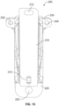
- FIG 15 is a top view of bolster spring 200.
- mounting hole 222 of the bottom plate 220 extends beyond the elastomer zone.
- mounting holes 232 and 234 on angled flange 230 extend outwardly from the bottom plate 220 and have a spacing that is wider than the width of the bottom plate 220 and the top plate 210. This wide spacing of the mounting holes 232 and 234 on angled flange 230 advantageously provides for greater contact between the angled flange surfaces when mounted as shown in Figure 26 , resulting in a stronger mechanical j oint being formed between the angled flanges of the bolster springs.
- bolster spring 200 The particular configuration of the base plate 220, top plate 210, and intermediate plates 250, 252, and 254 of bolster spring 200 is illustrative only, and these components may have a variety of geometries and configurations.
- the bolster spring 200 is not required to have, but may have, the geometry shown in Figures 9-15 .
- the use of a tie-bar may be, but is not required to be, included.
- Elastomeric sections 260, 262, 264, and 266 may comprise an elastomeric material (i.e., an elastomer) such as natural rubber, synthetic rubber, styrene butadiene, synthetic polyisoprene, butyl rubber, nitrile rubber, ethylene propylene rubber, polyacrylic rubber, high-density polyethylene, thermoplastic elastomer, a thermoplastic olefin (TPO), urethane, polyurethane, a thermoplastic polyurethane (TPU), or some other type of elastomer.
- an elastomeric material i.e., an elastomer
- an elastomeric material such as natural rubber, synthetic rubber, styrene butadiene, synthetic polyisoprene, butyl rubber, nitrile rubber, ethylene propylene rubber, polyacrylic rubber, high-density polyethylene, thermoplastic elastomer, a thermoplastic olef
- the load cushion 300 may be mounted with the cushion portion 330 extending either above or below the bottom plate 310. Likewise, the load cushion 300 may be mounted such that the top plate 310 extends beneath the bottom plate 320. Therefore, the use of the terms “top” and “bottom” are used simply to describe the plates 310 and 320 that are attached to the load cushion portion 330, and do not in any way require that the load cushion 300 is mounted in any particular configuration.
- Figure 24 is a perspective view of the inboard side of equalizing beam 100 and Figure 25 is a top view of equalizing beam 100.
- Beam hubs 102 and 104 are located on opposite ends of the equalizing beam 100.
- Shock absorber mount 106 having mounting hole 106a and shock absorber mount 108 having mounting hole 108a are shown positioned on the inboard side of the equalizing beam 100.
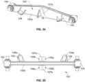
- Bolster spring mounts 107a and 107b extend from opposite sides of the center of equalizing beam 100.
- ears 436 and 438 of the suspension subassembly shown in Figures 34-36 may be secured to a corresponding suspension subassembly with a common fastener in the same manner as shown in suspension 50 and bolster springs 200.
- the nut-shaped head on an M12 bolt has a thickness of 12mm, whereas the low-profile head on an equivalent bolt may have a thickness of 3-6 mm.
- the head of fasteners 443b', 441b', 441a', and 443a' is shown as round, although it could other shapes, such as square or hexagonal.
- fasteners 443b' and 441b' may have a stud that is knurled and which may be advantageously press fit into corresponding holes in rearwardly extending mounting flange 440b and a bottom of the low profile head may be drawn into engagement with surfaces 474 and 472 respectively of tie-bar 470 by tightening a nut onto a threaded end of the stud.
- Fasteners 441a' and 443b' may be configured in the same manner and press fit into corresponding rearwardly extending mounting flange 440a and drawn into engagement with surfaces of tie-bar 470 in the same manner.
Landscapes
- Engineering & Computer Science (AREA)
- Mechanical Engineering (AREA)
- General Engineering & Computer Science (AREA)
- Architecture (AREA)
- Springs (AREA)
- Vehicle Body Suspensions (AREA)
Description
- The present invention generally relates to vehicle suspensions. More particularly, the present invention relates to vehicle suspensions using bolster springs.
WO2016/053360 discloses a bolster spring in accordance with the preamble of claim 1 and describes a vehicle suspension including first and second bolster springs, including upwardly extending flanges with mounting holes, on the bottom of the first and second bolster springs. - In one aspect, a bolster spring for a vehicle suspension is provided as claimed in claim 1.
- Exemplary embodiments of the invention are described herein with reference to the drawings, wherein like parts are designated by like reference numerals, and wherein:
-
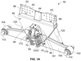
Figure 1A is a perspective view of the outboard side ofvehicle suspension 50, according to a non-claimed example; -
Figure 1B is a perspective view ofvehicle suspension 50 shown inFigure 1 and oppositely disposedvehicle suspension 50; -
Figure 2 is a front view of the outboard side ofvehicle suspension 50 shown inFigures 1A and1B ; -
Figure 3 is a perspective view of the inboard side ofvehicle suspension 50 shown inFigures 1A ,1B , and2 ; -
Figure 4 is a rear view of the inboard side ofvehicle suspension 50 shown inFigures 2 and 3 ; -
Figure 5 is a bottom view ofvehicle suspension 50 shown inFigures 1A-4 ; -
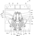
Figure 6 is a top view ofvehicle suspension 50 shown inFigures 1A-5 ; -
Figure 7 is a right side view ofvehicle suspension 50 shown inFigures 1A-6 ; -
Figure 8 is a left side view ofvehicle suspension 50 shown inFigures 1A-7 ; -
Figure 9 is a close up front view ofvehicle suspension 50 showingbolster springs -
Figure 10 is a close up front perspective view ofvehicle suspension 50 shown inFigure 9 ; -
Figure 11 is a perspective view ofbolster spring 200, according to a non-claimed example, provided for reference purposes; -
Figure 12 is a perspective bottom view ofbolster spring 200 shown inFigure 11 ; -
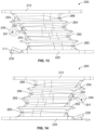
Figure 13 is a left side view ofbolster spring 200 shown inFigures 11 and 12 ; -
Figure 14 is a right side view ofbolster spring 200 shown inFigures 11-13 ; -
Figure 15 is a top view ofbolster spring 200 shown inFigures 11-14 ; -
Figure 16A is a perspective top view ofload cushion 300, according to a non-claimed example; -
Figure 16B is a perspective bottom view ofload cushion 300 shown inFigure 16A ; -
Figure 17 is a right side view ofload cushion 300 shown inFigures 16A-16B ; -
Figure 18 is frontview load cushion 300 shown inFigures 16A-17 ; -
Figure 19 is a bottom view ofload cushion 300 shown inFigures 16A-18 ; -
Figure 20 is a top view ofload cushion 300 shown inFigures 16A-19 ; -
Figure 21A is a cross-sectional, perspective view of the inboard side ofvehicle suspension 50, taken alongline 21A-21A inFigure 4 ; -
Figure 21B is a cross-sectional, perspective view of the outboard ofvehicle suspension 50, taken alongline 21B-21B inFigure 2 ; -
Figure 22A is a cross-sectional, perspective view of the inboard side ofvehicle suspension 50, taken alongline 22A-22A inFigure 4 ; -
Figure 22B is a cross-sectional, perspective view of the outboard ofvehicle suspension 50, taken alongline 22B-22B inFigure 2 ; -
Figure 23A is a cross-sectional, perspective view of the inboard side ofvehicle suspension 50, taken alongline 23A-23A inFigure 4 ; -
Figure 23B is a cross-sectional, perspective view of the outboard ofvehicle suspension 50, taken alongline 23B-23B inFigure 2 ; -
Figure 24 is a perspective view of equalizingbeam 100 ofvehicle suspension 50 shown inFigures 1A-10 ; according to a non-claimed example; -
Figure 25 is a top view of equalizingbeam 100 shown inFigure 24 ; -
Figure 26 is a close up view showing howbolster springs -
Figure 27 is a perspective view ofbolster spring 400 according to an embodiment of the claimed invention; -
Figure 28 is a rear view ofbolster spring 400; -
Figure 29 is a front view ofbolster spring 400; -
Figure 30 is a right side view ofbolster spring 400; -
Figure 31 is a left side view ofbolster spring 400; -
Figure 32 is a top view ofbolster spring 400; -
Figure 33 is a bottom view ofbolster spring 400; -
Figure 34 is a bottom view of a suspension subassembly includingbolster springs -
Figure 35 is a perspective view of a suspension subassembly includingbolster springs Figure 34 ; -
Figure 36 is another perspective view of a suspension subassembly shown inFigures 34 and35 , includingbolster springs -
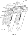
Figure 37 is a perspective view of a suspension subassembly includingbolster springs -
Figure 38 is another perspective view of a suspension subassembly shown inFigure 37 ; and -
Figure 39 is a perspective view of tie-bar 470 shown inFigures 37 and38 withfasteners 443b' and 441b'. -
Figures 1A-10 provide various views ofvehicle suspension 50.Vehicle suspension 50 is designed to support longitudinally extending vehicle frame rails (not shown) which can be of various types that are positioned above laterally extending vehicle axles. As will be appreciated by those skilled in the art, components ofvehicle suspension 50 are duplicated on each side of the vehicle as shown inFigure 1B . It will also be appreciated that vehicle wheels may be mounted to the ends of the vehicle axles in a known manner. Further, it will be appreciated that the vehicle frame rails may be connected by one or more vehicle frame cross members. - Those skilled in the art will further understand that a suspension, arranged in accordance with the
suspension 50 and the components thereof, alternatively may be attached to frame rails of a trailer (for example, a trailer that connects to a semi-tractor). The frame rails of a trailer may comprise frame rails such as those described above or another type of frame rail. - For purposes of this description, unless specifically described otherwise, hereinafter, "vehicle" refers to a vehicle or a trailer. In this way, for example, a vehicle frame refers to a vehicle frame or a trailer frame. Furthermore, for purposes of this description, the left side of a vehicle refers to a side of the vehicle on an observer's left-hand side when the observer faces the back of the vehicle, and the right side of the vehicle refers to a side of the vehicle on an observer's right-hand side when the observer faces the back of the vehicle. Furthermore still, for purposes of this description, "outboard" refers to a position further away from a center line, running from the front to the back of a vehicle, relative to "inboard" which refers to a position closer to that same center line.
-
Figure 1A is a perspective view of an outboard side ofvehicle suspension 50 having aframe attachment portion 62 that is adapted for attachment to a vehicle frame or frame rail with a plurality ofmounting holes 63.Frame attachment portion 62 includesouter gussets central flange 64 that provide additional strength and rigidity to thevehicle suspension 50.Frame attachment portion 62 is attached to saddle 60. Bolstersprings saddle 60 and a bottom attached to walls of bolsterspring mount 107b positioned on equalizingbeam 100.Equalizing beam 100 has abeam hub 102 on a first end and abeam hub 104 on a second end.Beam hub 102 includes abar pin 110 adapted for attachment to a first axle (not shown) andbeam hub 104 includes abar pin 112 adapted for attachment to a second axle (not shown). - A pair of
shock absorbers beam 100 and another end mounted to saddle 60 on the inboard side ofvehicle suspension 50. In some applications, shock absorbers may not be used. Aload cushion 90 is mounted to loadcushion mount 94 extending fromsaddle 60 andload cushion 90 is positioned beneathsaddle 60 and positioned inwardly from and generally above bolstersprings first rebound strap 80 is mounted to loadcushion mount 94, and a second rebound strap is mounted to load cushion mount 92 (shown inFigure 3 ). Abracket 191 having U-shaped ends that are used to mount rebound straps 80 may be positioned between the load cushion and the load cushion mounts 92 and 94. In addition, shims of varying thickness may positioned between theload cushion 90 andbracket 191 to change the ride characteristics of thevehicle suspension 50. -
Figure 1B includes asecond vehicle suspension 50a that is a mirror image ofvehicle suspension 50, and may be positioned on an opposite side of a vehicle frame. Accordingly,Figure 1B provides a perspective view of the inboard side ofvehicle suspension 50a.Vehicle suspension 50a includes aframe attachment portion 62a that is adapted for attachment to a vehicle frame or frame rail with a plurality of mountingholes 63a.Frame attachment 62a further includesouter gussets vehicle suspension 50a.Frame attachment portion 62a is attached to saddle 60a. Bolstersprings 71a and 73a are provided that each have a top attached to bolster spring spring mounts extending from the inboard side ofsaddle 60a and a bottom attached to bolsterspring mount 107a positioned on equalizingbeam 100a. Equalizingbeam 100a has abeam hub 102a on a first end and abeam hub 104a on a second end.Beam hub 102a includes abar pin 110a adapted for attachment to a second axle (not shown) andbeam hub 104a includes abar pin 112a adapted for attachment to a first axle (not shown). - A pair of
shock absorbers beam 100a and another end mounted to the inboard side ofsaddle 60a. A load cushion is mounted to loadcushion mount 92a extending fromsaddle 60a. Arebound strap 80a is mounted to loadcushion mount 92a. -
Figure 2 provides a front view of the outboard side ofvehicle suspension 50 andFigures 3 and4 provide views of the inboard side ofvehicle suspension 50. InFigure 2 ,load cushion 90 is shown mounted to loadcushion mount 94 extending fromsaddle 60. Bolstersprings outboard wall 65 ofsaddle 60, and also to bolsterspring mount 107b on the outboard side of the equalizingbeam 100. As shown inFigure 3 , bolstersprings inboard wall 67 ofsaddle 60 and to walls of bolsterspring mount 107a positioned on the inboard side of the equalizingbeam 100. The configuration of bolster springs 70-73 results in a balanced, split bolster spring arrangement where one pair of bolstersprings beam 100 and one pair of bolstersprings beam 100. - As shown in
Figure 3 ,shock absorber 120 has a first end secured to mount 108 positioned on equalingbeam 100 and a second end secured to mount 69 positioned onsaddle 60, andshock absorber 122 has a first end secured to mount 106 positioned on equalizingbeam 100 and a second end secured to mount 13 positioned onsaddle 60. In other examples, the second ends ofshock absorbers - Prior vehicle suspensions employing bolster springs typically provided an acute angle, or apex angle, between the bottoms of the bolster springs of 53 degrees, which has become a de facto industry standard. However, as best shown in
Figures 2 and9 ,vehicle suspension 50 significantly departs from the de facto apex angle standard of 53 degrees. In particular, an apex angle α is provided that is significantly less than 53 degrees. In the examples shown inFigures 1-10 , the apex angle α between the bottom of bolstersprings 72 and 70 (and the apex angle between bolstersprings 71 and 73) is 37 degrees. While an apex angle of 37 degrees is preferred, the apex angle α may range between 34-40 degrees, or from 30-45 degrees, all lower than a standard apex angle of 53 degrees. - By reducing the apex angle α to 37 degrees, a number of important advantages are achieved. For example, the reduced apex angle α allows the springs to be positioned closer together, and thereby taking up less space longitudinally. In turn, a greater clearance between the vehicle tires and the bolster spring arrangement is provided, which may provide greater tire chain clearance or allow for the use of larger tires. In addition, by reducing the apex angle α, the bolster springs are put more into a shear, rather than compression. As a result, a lower primary vehicle spring rate may be achieved, while at the same time providing for increased longitudinal stiffness. The present configuration of the bolster springs with an apex angle α of 37 degrees has increased the longitudinal stiffness of the suspension resulting in a corresponding decrease in the longitudinal deflection to less than an inch. As a result, the reduced apex angle α has resulted in reduced axle translation along the SAE X-Axis during braking and acceleration.
- Reducing the apex angle α between the bolster springs has advantageously resulted in a reduction in the primary suspension spring rate to 1.5-2.0 kN/mm depending upon the elastomer used to create the bolster springs. Furthermore, a secondary spring rate of the vehicle suspension when the load cushion is engaged measured at 1.0g ranges from 2.0-3.5 kN/mm depending upon the elastomers chosen for both the bolster springs and initial gap between the load cushion and its reaction plate. These primary and second vehicle suspension spring rates are orders of magnitude lower than traditional elastomeric suspensions and are on the same order of magnitude as parabolic 6-rod suspensions.
- Additionally, as discussed in more detail below with respect to
Figure 26 , in addition to reducing the apex angle α between the bolstersprings vehicle suspension 50 also incorporates a unique bolster spring mounting arrangement wherein anangled flange 230 on thebottom plate 220 of bolsterspring 70 is directly mounted to a correspondingangled flange 230 onbottom plate 220 of bolsterspring 72 using a pair of common fasteners for retention. Bolstersprings - Directly mounting bolster
springs springs - As known to those skilled in the art, a mechanical joint formed between two components improves retention integrity and can permit the use of smaller fasteners compared to typical bolster spring designs. A benefit of smaller fasteners is improved clearances to surrounding packages, a more weight optimized design, and improved serviceability because smaller fasteners require less torque to achieve design load as a percent of proof load. Therefore, smaller fasteners are more easily and likely to be tightened appropriately.
-
Figure 5 is a bottom view ofvehicle suspension 50. From this view, the equalizingbeam 100 is shown with beam hub104 havinginboard side 104a on one end withbar pin 112 and withbeam hub 102 havinginboard side 102a withbar pin 110. A center-plane 100c of equalizingbeam 100 is shown offset towardsinboard side 104a andinboard side 102a a distance d from a center-plane ofbeam hubs - In
Figure 5 , there is a clear view of bolsterspring 70 and bolsterspring 72 mounted to opposing walls of bolsterspring mount 107b extending from an outboard side thevehicle suspension 50, as well as of bolsterspring 71 and bolsterspring 73 mounted to opposing walls of bolsterspring mount 107a extending from the inboard side ofvehicle suspension 50. -
Figure 6 shows a top view ofvehicle suspension 50. InFigures 5 and 6 ,shock absorbers gap 105 is shown on the surface ofbeam hubs plane 100c. InFigure 6 ,load cushion mount 94 is shown extending from an outboard side ofsaddle 60 andload cushion mount 92 is shown extending from an inboard side ofsaddle 60. In addition,central flange 64 is shown positioned ontop surface 91 ofsaddle 60 attached to frameattachment portion 62. -
Figure 7 is a right side view ofvehicle suspension 50 andFigure 8 is a left side view ofvehicle suspension 50.Beam hub 102 is shown withbar pin 110 adapted for attachment to a first axle (not shown) andbeam hub 104 is shown withbar pin 112 adapted for attachment for a second axle (not shown).Frame attachment portion 62 withgussets outboard wall 65 andinboard wall 67 of the saddle andload cushion mount 94 is shown extending from the outboard side ofvehicle suspension 50.Shock absorber 122 is shown mounted toshock absorber mount 13 andshock absorber 120 is shown mounted toshock absorber mount 69. In addition, a pair of rebound straps 80 are shown extending from inboard and outboards sides of thevehicle suspension 50. Rebound straps 80 serve to prevent bolster springs 70-73 from being overstretched and overstressed whenvehicle suspension 50 is placed in hang or rebound, such as when a vehicle is lifted with an outrigger, hits a large pothole, or during a sudden drop when going over a steep drop in the road. -
Figure 9 is a close up front view of, andFigure 10 is a close up perspective view of, the bolstersprings load cushion 90 on the outboard side ofvehicle suspension 50. Bolsterspring 70 is attached to bolsterspring mount 170 onsaddle 60 usingfasteners spring mount 107a on the equalizingbeam 100 usingfastener 270a. Similarly, bolsterspring 72 is attached to bolsterspring mount 172 onsaddle 60 usingfasteners spring mount 107a on the equalizingbeam 100 usingfastener 272a. As illustrated inFigure 26 , upwardly extendingflange 230 of bolsterspring 70 is directly mounted to a corresponding upwardly extendingflange 230 of bolsterspring 72 using common fasteners, with a portion ofspring saddle 193 positioned therebetween. In other examples, the bolstersprings flanges 230 may be directly mounted to each other using common fasteners without a portion of a spring saddle positioned between them. As discussed above, apex angle α is formed between the bottom plates of bolstersprings - To further strengthen the bolster spring assembly, a tie-
bar 130 is used to tie outboard bolsterspring 70 to inboard bolster spring 71 (shown inFigure 3 andFigure 5 ) and tie-bar 132 is used to tie inboard bolsterspring 72 to inboard bolster spring 73 (shown inFigure 3 andFigure 5 ). In this example, the tie-bar is mounted in an intermediate plate located at a midpoint between the top plate and bottom plate of the bolster spring. The midpoint is the point most susceptible to buckling, bulging, or splaying. Therefore, the tie-bar serves to react the inboard and outboard bolster springs to prevent buckling or bulging at the most vulnerable point on the bolster spring. The tie-bar therefore provides greater rigidity and strength to the bolster spring assembly. - Furthermore, by directly mounting bolster
spring 70 to bolsterspring 72 with common fasteners and directly mounting bolsterspring 71 to bolsterspring 73 with common fasteners, and by connecting bolsterspring 70 to bolsterspring 71 using tie-bar 130 and by connecting bolsterspring 72 to bolsterspring 73 using tie-bar 132, all four bolstersprings - In addition, as shown in
Figures 9 and10 ,load cushion 90 is secured to outboard load cushion mount 94 (and to inboardload cushion mount 92 shown inFigure 4 ), and is positioned abovereaction plate 190. Reboundstrap 80 is attached to reboundstrap flange 80a and to reboundstrap flange 80b. Thereaction plate 190 is secured via attachment to reboundstrap flange 80b. In this example, a bottom surface of theload cushion 90 is positioned a distance D above thereaction plate 190. Distance D may preferably be 19 mm. Therefore, a primary spring rate is based on the bolster springs, and when theload cushion 90 engages thereaction plate 190, a secondary spring rate that includes theload cushion 90 is provided. In this example, a hard stop has been included at 68 mm of travel to protect the bolster springs and load cushion from becoming overcompressed. - The hard stop feature is best shown in
Figures 22A and 22B , wherefasteners 290a used to mount theload cushion 90 downwardly extend towards thereaction plate 190.Sleeves 291 are positioned around thefasteners 290a and in thisexample fasteners 290a have ahead 293 extending from the end ofsleeves 291. Whenload cushion 90 is significantly compressed, e.g. at 50% compression, theheads 293 offasteners 290a that contact thereaction plate 190 to provide a hard stop and prevent further compression of theload cushion 90. In other examples, the bottom ofsleeves 291 may be counterbored to enclosehead 293 so that thehead 293 does not extend from the bottom of thesleeve 291 and instead the bottom of thesleeve 291 contacts thereaction plate 190 to provide the hard stop. The bottom of thesleeve 291 has a greater surface area thanhead 293 offasteners 290a to spread the forces upon impact with thereaction plate 190. As a result of the hard stop, there is a ceiling on the amount of strain that will experienced by the bolster springs and load cushion. In this example, therebound strap 80 is comprised of woven material that is advantageously removable to allow for easy repair or replacement of therebound strap 80. It should be noted that depending upon the application, the disclosed vehicle suspensions may be used without a load cushion. - The components of the
vehicle suspension 50 shown inFigures 1-10 may comprise cast or fabricated metal or composite material, including iron, steel, or aluminum.Frame attachment portion 62 andsaddle 60, and equalizingbeam 100 could also be cast with any suitable castable material. Similarly, thesaddle 60 may comprise cast or fabricated metal or composite material. Depending on the application, the metal may, for example, be nodular ductile iron (or more simply, ductile iron), steel, such as a high strength low alloy steel, or aluminum. Typically, high strength low alloy steels are a preferred material to use for the frame hanger and the saddle, although aluminum is often desired when weight considerations are of greater importance. -
Figures 11-15 are views of a bolsterspring 200. Bolster springs 70, 71, 72, and 73 may be configured as bolsterspring 200. As shown inFigures 11-14 , bolsterspring 200 includes abase plate 220 and atop plate 210. Bolsterspring 200 includes anelastomeric section 260 betweenbase plate 220 andintermediate plate 250, anelastomeric section 262 betweenintermediate plate 250 andintermediate plate 252, anelastomeric section 264 betweenintermediate plate 252 andintermediate plate 254, and anelastomeric section 266 betweenintermediate plate 254 andtop plate 210. It should be noted that in other examples a greater or lesser number of intermediate plates can be used, including no intermediate plates. -
Top plate 210 includes mountingholes hole 212 located on a flange on a first end oftop plate 210 and mountinghole 214 located on a flange on a second end oftop plate 210. Such a mounting hole arrangement allows for mounting to a bolster spring mount without using studs extending from the elastomer zone.Bottom plate 220 includes mountinghole 222 that is positioned on a flange on a first end ofbottom plate 220 that is also beyond the elastomer zone. Anangled flange 230 extends from a second end ofbottom plate 220.Angled flange 230 includes a pair of spaced mountingholes Figure 26 .Top plate 210 andbottom plate 220 advantageously extend beyond the elastomer zone, and may be formed complementary in shape with the mounting surface of a bolster spring mount to provide a larger mounting surface area, which forms a stronger mechanical joint. - As shown in
Figures 13 and 14 ,angled flange 230 may extend at an angle that is one half of apex angle α, so that when directly mounted to the angled flange of an adjacent bolster spring having the same configuration, an apex angle α is formed between the bottom surfaces of the directly connected bolster springs. In addition, a tie-bar mounting extension 240 having a throughhole 241 through which a tie-bar may extend is shown extending from centerintermediate plate 252. -
Figure 15 is a top view of bolsterspring 200. As can be seen, mountinghole 222 of thebottom plate 220 extends beyond the elastomer zone. In addition, mountingholes angled flange 230 extend outwardly from thebottom plate 220 and have a spacing that is wider than the width of thebottom plate 220 and thetop plate 210. This wide spacing of the mountingholes angled flange 230 advantageously provides for greater contact between the angled flange surfaces when mounted as shown inFigure 26 , resulting in a stronger mechanical j oint being formed between the angled flanges of the bolster springs. - The particular configuration of the
base plate 220,top plate 210, andintermediate plates spring 200 is illustrative only, and these components may have a variety of geometries and configurations. Thus, the bolsterspring 200 is not required to have, but may have, the geometry shown inFigures 9-15 . Furthermore, the use of a tie-bar may be, but is not required to be, included. - A bolster spring is typically constructed from relatively flat first and second end plates with an elastomer connected between them. This spring will then have compressive and shear rates corresponding to the chosen material, cross-section, and thickness of elastomer. In accordance with the disclosed examples, bolster
spring 200 may be constructed ofelastomeric sections plates Elastomeric sections elastomeric sections - In another respect,
elastomeric sections spring 200 is under a load within a given range and when that load is removed, and (ii) has non-elastic characteristics (for example, does not return to an original non-loaded shape) if the applied load exceeds the greatest load of the given range. The given range may extend from no load to a maximum expected load plus a given threshold. The given threshold accounts for possible overloading of bolsterspring 200. As an example, the viscoelastomeric material may comprise amorphous polymers, semi-crystalline polymers, and biopolymers. Other examples of the viscoelastomeric material are also possible. - In accordance with the examples,
elastomeric sections elastomeric sections - Bolster
spring 200 may be formed, for example, by inserting theplates - In a preferred example any exposed portion of the plates (for example, a portion of the plates not covered by the elastomeric material) is protected against corrosion by a means other than the elastomeric material. In other examples, some exposed portions of the plates (e.g., the edges of the plates) may not be protected against corrosion, whereas any other exposed portions of the plates are protected against corrosion.
- The
plates plates -
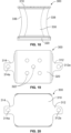
Figures 16A and 16B are perspective views of anexample load cushion 300 for use invehicle suspension 50.Figure 17 is a side view,Figure 18 is a front view,Figure 19 is a bottom view, andFigure 20 is a top view ofload cushion 300.Load cushion 90 shown invehicle suspension 50 inFigures 1-10 may be arranged asload cushion 300. - As shown in one or more of
Figures 16A-20 ,load cushion 300 includes atop plate 310, abottom plate 320, and aload cushion portion 330.Top plate 310 includes mountingflange 312 with mountinghole 312a and mountingflange 314 with mountinghole 314a adapted for mounting to load cushion mounts 92 and 94 (shown inFigures 2 and4 ) ofvehicle suspension 50. In this example, a horizontal cross section of thecushion portion 330 is generally square with rounded corners, although it could also be generally circular, rectangular, or conic. As shown inFigure 16B and19 , thebottom plate 320 includesholes 322 that are used during the molding process to provide a passage for the elastomeric material that forms thecushion portion 330. - As shown in
Figure 17 , theload cushion portion 330 has a unique symmetrical shape that includes curvilinear front and rearouter surfaces top plate 310 andbottom plate 320 such that the narrowest thickness of theload cushion 330 occurs at the midpoint. Similarly, as shown inFigure 18 , theload cushion portion 330 has a unique symmetrical shape that includes curvilinear left and rightouter surfaces top plate 310 andbottom plate 320 such that the narrowest thickness of theload cushion 330 occurs at the midpoint. -
Load cushion 330 may have a cross section where front and rearouter surfaces cushion 330 may have a cross section where left and rightouter surfaces load cushion portion 330 may be shaped as a hyperboloid. The curved outer surfaces of the load cushion portion result in a much lower elastomeric strain on the load cushion for the same deflection as compared to a linearly reduced cross-section. - The
load cushion 90 may undergo 50% compression at full jounce, or when the hard stop discussed above is reached. At this point, the cross-section of theload cushion portion 330 changes from a negative Gaussian curvature to a 0 or slightly positive Gaussian curvature. As used herein the term, 0 Gaussian curvature means that the outer surfaces of the cross-section are parallel, and a "slightly positive Gaussian curvature" means that the midpoint of theload cushion portion 330 becomes wider than the end sections, by up to 1 cm on each side of the load cushion portion. - It will be appreciated that
bottom plate 320 is not required, and theload cushion 330 may have an exposed surface instead of havingbottom plate 320. The use of abottom plate 320 does not affect in any significant way the load cushion load versus deflection curve. However, thebottom plate 320 may be incorporated to protect the active elastomer of theload cushion portion 330 from debris such as rocks that could inadvertently end up on the reaction plate that is positioned beneath the load cushion. Debris could become embedded temporarily or permanently into the elastomer and create an undesirable crack initiation site. - The
bottom plate 320 may be encapsulated to provide for improved corrosion resistance, elimination of metal to metal contact resulting in noise reduction upon contact with the reaction plate, improved friction between theload cushion 300 and the reaction plate 190 (shown inFigures 9 and10 ) to reduce or minimize wear between thebottom plate 320 and thereaction plate 190 during vehicle motion because relative motion is decreased or eliminated. In addition, encapsulation may be used as a service wear and replacement indicator similar to wear bars found between tire treads. -
Load cushion 300 may have a continuously increasing spring rate as an applied load increases and a continuously decreasing spring rate as an applied load decreases, due to it generally conic shape. - The
top plate 310 andbase plate 320 may be constructed of any of a variety of suitable materials, including, but not limited to, iron, steel, aluminum, plastic, and a composite material. As an example, the base plate can comprise a plate having a thickness between a range of 0.188 inches (3.00 mm) to 0.25 inches (6.35 mm), or more. The plates can be encapsulated in elastomer and/or bonded to the load cushion portion using a bonding agent. The plate dimensions and shape can be varied to any dimension or shape desired for packaging, weight, and aesthetics. Preferably, the load cushiontop plate 310 is dimensioned to (i) match the surface of the load cushion mount described herein, such as load cushion mounts 92 and 94, (ii) locate mounting holes for securing theload cushion 300 to the load cushion mounts 92 and 94, and (iii) minimize overall mass. - The size and dimensions of the elastomer used for the
cushion portion 330 ofload cushion 300 may be optimized for the vertical spring rate requirements. As noted above, the vertical spring rate for the load cushions 300 may continuously increase with increasing load and continuously decreases with decreasing load, defining a curvilinear shape with no discontinuities on a graph illustrating spring rate as a function of sprung load. - Preferably,
load cushion portion 330 has a generally conic shape as it extends towards a midpoint betweentop plate 310 andbottom plate 320. With this preferred shape, the vertical spring rate for theload cushion 300 linearly increases with increasing load and linearly decreases with decreasing load. In this regard,load cushion 300 is operable as a progressive spring rate load cushion. In one example, the cross section ofload cushion portion 330 adjacenttop plate 310 and adjacentbottom plate 320 is 110 mm by 110 mm. At the midpoint between thetop plate 310 and thebottom plate 320 theload cushion portion 330 the cross section is 88 mm by 88 mm, and the height ofload cushion portion 330 is 105 mm not including plates or wear layer encapsulation. Other example dimensions of portions ofload cushion 300 are also possible. For a given geometry, the spring rate ofload cushion 300 may be optimized by varying the durometer of the elastomer. By varying the durometer, a family of interchangeable progressive spring rate load cushions can be created. - It will further be appreciated that the
load cushion 300 may be mounted with thecushion portion 330 extending either above or below thebottom plate 310. Likewise, theload cushion 300 may be mounted such that thetop plate 310 extends beneath thebottom plate 320. Therefore, the use of the terms "top" and "bottom" are used simply to describe theplates load cushion portion 330, and do not in any way require that theload cushion 300 is mounted in any particular configuration. -
Figure 21A is a cross sectional inboard perspective view ofvehicle suspension 50 taken alongline 21A-21A shown inFigure 4 , andFigure 21B is a cross sectional inboard perspective view ofvehicle suspension 50 taken alongline 21B-21B shown inFigure 2 .Frame attachment portion 62 with mountingholes 63 is shown extending upwardly fromupper surface 91 of the saddle withcentral flange 64 andgusset 68.Shock absorber 122 is shown mounted toinboard surface 67 of the saddle and reboundstrap 80 is shown extending beneathload cushion mount 92. Bolstersprings beam 100. Similarly, bolstersprings beam 100. In addition,common fastener 71b is shown directly mounting bolsterspring 71 to bolsterspring 73 andcommon fastener 70b is shown directly mounting bolsterspring 70 to bolsterspring 72. -
Figure 22A is a cross sectional inboard perspective view ofvehicle suspension 50 taken alongline 22A-22A shown inFigure 4 , andFigure 22B is a cross sectional outboard perspective view ofvehicle suspension 50 taken alongline 22B-22B shown inFigure 2 .Frame attachment portion 62 with mountingholes 63 is shown extending upwardly fromupper surface 91 of the saddle withcentral flange 64 andgusset 68.Shock absorber 122 is shown mounted toinboard surface 67 of the saddle and reboundstraps 80 are shown extending on opposite sides ofload cushion 90.Load cushion 90 can be seen positioned directly abovereaction plate 190.Load cushion 90 is also shown mounted to the load cushion mounts extending fromwalls saddle using fasteners 290a. -
Spring saddle 193 is shown supportingreaction plate 190.Throughhole 70d is positioned inreaction plate 190 to allow a fastener to extend therethrough for mounting together the angled flanges of bolstersprings reaction plate 190 to allow a fastener to extend therethrough for mounting together the angled flanges of bolstersprings - In addition, equalizing
beam 100 is shown having a U-shaped cross section withopposed walls bolt 101 having asleeve 103 is used to tie the twowalls bolt 101 is used to relieve stress in the equalizingbeam 100 where the bolster springs 70-73 are attached by "pinching"walls sleeve 103. -
Figure 23A is a cross sectional inboard perspective view ofvehicle suspension 50 taken alongline 23A-23A shown inFigure 4 , andFigure 23B is an outboard perspective cross sectional view ofvehicle suspension 50 taken alongline 23B-23B shown inFigure 2 .Frame attachment portion 62 with mountingholes 63 is shown extending upwardly fromupper surface 91 of the saddle withcentral flange 64 andgusset 68.Shock absorber 122 is shown mounted toinboard surface 67 of the saddle and reboundstraps 80 are shown extending on opposite sides ofload cushion 90.Load cushion 90 can be seen positioned directly abovereaction plate 190.Load cushion 90 is also shown mounted to the load cushion mounts extending fromwalls -
Figure 24 is a perspective view of the inboard side of equalizingbeam 100 andFigure 25 is a top view of equalizingbeam 100.Beam hubs beam 100.Shock absorber mount 106 having mountinghole 106a andshock absorber mount 108 having mountinghole 108a are shown positioned on the inboard side of the equalizingbeam 100. Bolster spring mounts 107a and 107b extend from opposite sides of the center of equalizingbeam 100. On the inboard side, the walls of bolsterspring mount 107a include mountingholes springs 71 and 73 (shown inFigure 3 ), and on the outboard side, the walls of bolsterspring mount 107b include mountingholes springs 70 and 72 (shown inFigure 2 ). - The equalizing
beam 100 is shown in an illustrative configuration. However, equalizingbeam 100 may be constructed in any of a variety of arrangements and with a variety of configurations and/or materials. -
Figure 26 provides an illustration showing how bolster springs 70 and 72 may be directly mounted to each other using common fasteners. In particular,flanges 230 of bolstersprings spring saddle 193 extending therebetween, wherein a pair of common fasteners may be used to directly mount the bolstersprings Spring saddle 193 may be formed from a pair of bent plates having a thickness of 6mm, such that theflanges 230 are positioned 12 mm apart. In addition, apex angle α is shown between the bottom surfaces ofbottom plates 220 of bolstersprings -
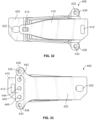
Figures 27-33 show various view of bolsterspring 400, that may be used insuspension assembly 50 described above. Bolsterspring 400 includes atop plate 410 having mountingapertures spring 400 also includes abottom plate 420 having mountingaperture 422.Intermediate plates top plate 410.Elastomeric section 460 is positioned betweenbottom plate 420 andintermediate plate 450.Elastomeric section 462 is positioned betweenintermediate plate 450 andintermediate plate 452.Elastomeric section 464 is positioned betweenintermediate plate 452 andintermediate plate 454.Elastomeric section 466 is positioned betweenintermediate plate 454 andtop plate 410.Elastomeric sections spring 200. In addition,top plate 410,bottom plate 420, andintermediate plates spring 200. -
Bottom plate 420 includes an extendingsection 430 from which upwardly extendingears gap 439 extends betweenears Ear 436 includes a mountingaperture 432 andear 438 includes a mountingaperture 434.Ears Intermediate plate 452 advantageously includes arearwardly extending flange 440 that includes mountingapertures -
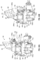
Figure 34 is a bottom view of a suspension subassembly including bolstersprings Figure 35 is a perspective view of a suspension subassembly including bolstersprings Figure 34 .Figure 36 is another perspective view of a suspension subassembly shown inFigures 34 and35 , including bolstersprings - Bolster
springs bar 470. Inparticular bolts bar 470 to rearwardly extendingflange 440a with nuts 445a and 447a respectively. Similarly,bolts bar 470 to rearwardly extendingflange 440b with nuts 445b and 447b.Gap 439 betweenears 436 and 438 (shown inFigure 27 ) provides clearance for the bolts to connect with therearwardly extending flange - It will be appreciated that
ears Figures 34-36 may be secured to a corresponding suspension subassembly with a common fastener in the same manner as shown insuspension 50 and bolstersprings 200. -
Figures 37-39 showalternate fasteners 443b' and 441b' that may be used to secure tie-bar 470 to rearwardly extending mountingflange 440b with nuts 447b and 445b, and alsoalternate fasteners 441a' and 443a' that may be used to secure tie-bar 470 to rearwardly extending mountingflange 440a with nuts 445a and 445b.Fasteners 443b', 441b', 441a', and 443a' differ fromfasteners fasteners 443b', 441b', 441a', and 443a' have a round, low-profile head that is much thinner than the nut-shaped head offasteners fasteners 443b', 441b', 441a', and 443a' is shown as round, although it could other shapes, such as square or hexagonal. - Although not required,
fasteners 443b' and 441b' may have a stud that is knurled and which may be advantageously press fit into corresponding holes in rearwardly extending mountingflange 440b and a bottom of the low profile head may be drawn into engagement withsurfaces bar 470 by tightening a nut onto a threaded end of the stud.Fasteners 441a' and 443b' may be configured in the same manner and press fit into corresponding rearwardly extending mountingflange 440a and drawn into engagement with surfaces of tie-bar 470 in the same manner. In other applications, thefasteners 443b', 441b', 441a', and 443a' may not have a knurled surface and may not be press fit into the corresponding mounting holes of rearwardly extending mountingflanges - The current tie-bar setup shown in
Figures 27-38 , with its fastener (rearwardly extending flange 440) that bolts two rate plates together is great for articulation levels up to a certain degree. In high severity applications, the bolster twists to the point where the curl plate itself (shown in bolster spring 200) starts to overcome the preload on the bolt, put the bolt in bending, and stress up the curl plates to where expensive material options would be the only fix (without affected packaging). - With the tie-bar forging with the
rearwardly extending flange 440 shown inFigures 27-38 , the bending stiffness can be tuned in multiple directions so that in severe applications the bar itself stresses up, keeps load out of the bolts, and allows the plates to rotate relative to one another (with the forging bending and/or twisting in between). This increases integrity of the entire joint, as the 1 main bolt moves to 4 separate bolts, distributing load, and the forging stresses up instead of the rate plates. - This has the added benefit of keeping high strength steel rate plates out of the mold, which are harder to use in processing. The forging doesn't need to go in the mold and can be tuned (material and process/design wise) for different applications of the same bolster.
- Example embodiments of the present invention have been described above. Those skilled in the art will understand that changes and modifications may be made to the described embodiments without departing from the scope of the present invention, which is defined by the claims.
Claims (1)
- A bolster spring (400) for a vehicle suspension comprising:a base plate (420);a top plate (410);elastomeric material (460, 462, 464, 466) positioned between the base plate (420) and the top plate (410);a first flange (430) having a bottom mounting surface upwardly extending from a first end of the base plate (420) at an angle 1/2 α;whereinthe first flange (430) comprising a pair of ears (436, 438); andone or more mounting holes (423, 434) positioned in the pair of ears (436, 438) in the first flange (430) adapted for attachment to a pair of ears on an upwardly extending flange on a second bolster spring; characterized in thatthe one or more mounting holes (432, 434) on the pair of ears (436, 438) on the first flange (430) have a gap positioned therebetween.
Applications Claiming Priority (2)
| Application Number | Priority Date | Filing Date | Title |
|---|---|---|---|
| US15/432,344 US10766325B2 (en) | 2014-09-29 | 2017-02-14 | Vehicle suspension |
| PCT/US2017/049266 WO2018151755A1 (en) | 2017-02-14 | 2017-08-30 | Vehicle suspension |
Publications (3)
| Publication Number | Publication Date |
|---|---|
| EP3582984A1 EP3582984A1 (en) | 2019-12-25 |
| EP3582984B1 true EP3582984B1 (en) | 2025-04-16 |
| EP3582984B8 EP3582984B8 (en) | 2025-05-28 |
Family
ID=59846680
Family Applications (1)
| Application Number | Title | Priority Date | Filing Date |
|---|---|---|---|
| EP17764982.9A Active EP3582984B8 (en) | 2017-02-14 | 2017-08-30 | Vehicle suspension |
Country Status (5)
| Country | Link |
|---|---|
| EP (1) | EP3582984B8 (en) |
| CN (1) | CN110494306A (en) |
| AU (1) | AU2017399666B2 (en) |
| CA (1) | CA3055906C (en) |
| WO (1) | WO2018151755A1 (en) |
Families Citing this family (4)
| Publication number | Priority date | Publication date | Assignee | Title |
|---|---|---|---|---|
| TR201922885A2 (en) * | 2019-12-31 | 2021-07-26 | Sem Lastik Sanayii Ve Ticaret Anonim Sirketi | CONNECTION WEDGE |
| CN112389146B (en) * | 2020-11-17 | 2024-09-13 | 梁乐 | Plate support for automobile suspension |
| CN114030437B (en) * | 2021-11-30 | 2024-01-19 | 电子科技大学长三角研究院(湖州) | A negative Gaussian curvature surface energy-absorbing structure |
| US12311721B2 (en) * | 2023-10-09 | 2025-05-27 | Good Rv Equipment Inc | Single axle suspension system and associated methods |
Family Cites Families (9)
| Publication number | Priority date | Publication date | Assignee | Title |
|---|---|---|---|---|
| US2216715A (en) * | 1937-04-09 | 1940-10-01 | Budd Edward G Mfg Co | Flexible support |
| GB648516A (en) * | 1948-11-03 | 1951-01-03 | Metalastik Ltd | Improvements relating to interleaved rubber springs |
| NL187015B (en) * | 1952-09-03 | Ashland Oil Inc | PROCESS FOR PREPARING METHYL, ETHYL OR PROPYLISOBUTYRATE. | |
| GB2252276A (en) * | 1991-01-29 | 1992-08-05 | Gkn Tadchurch Limited | Tandem axle vehicle suspension |
| US6206407B1 (en) * | 1998-12-18 | 2001-03-27 | Freightliner Llc | Vehicle suspension system |
| US6585286B2 (en) | 2000-12-12 | 2003-07-01 | The Boler Company | Vehicle suspension |
| US8302988B2 (en) * | 2008-03-10 | 2012-11-06 | Hendrickson Usa, L.L.C. | Suspension assembly with tie-plate |
| CN103192674B (en) * | 2013-04-17 | 2015-04-01 | 株洲时代新材料科技股份有限公司 | Autocrane rubber suspension system |
| US9604517B2 (en) * | 2014-09-29 | 2017-03-28 | Hendrickson Usa, L.L.C. | Vehicle suspension |
-
2017
- 2017-08-30 WO PCT/US2017/049266 patent/WO2018151755A1/en not_active Ceased
- 2017-08-30 EP EP17764982.9A patent/EP3582984B8/en active Active
- 2017-08-30 CA CA3055906A patent/CA3055906C/en active Active
- 2017-08-30 CN CN201780089593.5A patent/CN110494306A/en active Pending
- 2017-08-30 AU AU2017399666A patent/AU2017399666B2/en active Active
Also Published As
| Publication number | Publication date |
|---|---|
| EP3582984A1 (en) | 2019-12-25 |
| CA3055906A1 (en) | 2018-08-23 |
| CA3055906C (en) | 2024-04-09 |
| WO2018151755A1 (en) | 2018-08-23 |
| AU2017399666A1 (en) | 2019-09-12 |
| EP3582984B8 (en) | 2025-05-28 |
| AU2017399666B2 (en) | 2023-08-03 |
| CN110494306A (en) | 2019-11-22 |
Similar Documents
| Publication | Publication Date | Title |
|---|---|---|
| AU2018256534B2 (en) | Bolster spring | |
| JP5596050B2 (en) | Suspension assembly tie plate and frame hanger | |
| US8276927B1 (en) | Vehicle suspension and improved method of assembly | |
| US8720937B2 (en) | Load cushion for vehicle suspension | |
| US8152195B2 (en) | Modular suspension system and components thereof | |
| US8657315B2 (en) | Vehicle suspension and improved method of assembly | |
| US9004512B2 (en) | Shear spring useful for vehicle suspension | |
| EP3582984B1 (en) | Vehicle suspension | |
| US10766325B2 (en) | Vehicle suspension |
Legal Events
| Date | Code | Title | Description |
|---|---|---|---|
| STAA | Information on the status of an ep patent application or granted ep patent |
Free format text: STATUS: UNKNOWN |
|
| STAA | Information on the status of an ep patent application or granted ep patent |
Free format text: STATUS: THE INTERNATIONAL PUBLICATION HAS BEEN MADE |
|
| PUAI | Public reference made under article 153(3) epc to a published international application that has entered the european phase |
Free format text: ORIGINAL CODE: 0009012 |
|
| STAA | Information on the status of an ep patent application or granted ep patent |
Free format text: STATUS: REQUEST FOR EXAMINATION WAS MADE |
|
| 17P | Request for examination filed |
Effective date: 20190913 |
|
| AK | Designated contracting states |
Kind code of ref document: A1 Designated state(s): AL AT BE BG CH CY CZ DE DK EE ES FI FR GB GR HR HU IE IS IT LI LT LU LV MC MK MT NL NO PL PT RO RS SE SI SK SM TR |
|
| AX | Request for extension of the european patent |
Extension state: BA ME |
|
| DAV | Request for validation of the european patent (deleted) | ||
| DAX | Request for extension of the european patent (deleted) | ||
| STAA | Information on the status of an ep patent application or granted ep patent |
Free format text: STATUS: EXAMINATION IS IN PROGRESS |
|
| 17Q | First examination report despatched |
Effective date: 20210127 |
|
| GRAP | Despatch of communication of intention to grant a patent |
Free format text: ORIGINAL CODE: EPIDOSNIGR1 |
|
| STAA | Information on the status of an ep patent application or granted ep patent |
Free format text: STATUS: GRANT OF PATENT IS INTENDED |
|
| INTG | Intention to grant announced |
Effective date: 20241106 |
|
| GRAS | Grant fee paid |
Free format text: ORIGINAL CODE: EPIDOSNIGR3 |
|
| GRAA | (expected) grant |
Free format text: ORIGINAL CODE: 0009210 |
|
| STAA | Information on the status of an ep patent application or granted ep patent |
Free format text: STATUS: THE PATENT HAS BEEN GRANTED |
|
| AK | Designated contracting states |
Kind code of ref document: B1 Designated state(s): AL AT BE BG CH CY CZ DE DK EE ES FI FR GB GR HR HU IE IS IT LI LT LU LV MC MK MT NL NO PL PT RO RS SE SI SK SM TR |
|
| GRAT | Correction requested after decision to grant or after decision to maintain patent in amended form |
Free format text: ORIGINAL CODE: EPIDOSNCDEC |
|
| P01 | Opt-out of the competence of the unified patent court (upc) registered |
Free format text: CASE NUMBER: APP_11012/2025 Effective date: 20250306 |
|
| REG | Reference to a national code |
Ref country code: GB Ref legal event code: FG4D |
|
| REG | Reference to a national code |
Ref country code: CH Ref legal event code: PK Free format text: BERICHTIGUNG B8 Ref country code: CH Ref legal event code: EP |
|
| REG | Reference to a national code |
Ref country code: IE Ref legal event code: FG4D |
|
| REG | Reference to a national code |
Ref country code: DE Ref legal event code: R096 Ref document number: 602017088940 Country of ref document: DE |
|
| RAP4 | Party data changed (patent owner data changed or rights of a patent transferred) |
Owner name: HENDRICKSON USA, L.L.C. |
|
| REG | Reference to a national code |
Ref country code: SE Ref legal event code: TRGR |
|
| REG | Reference to a national code |
Ref country code: NL Ref legal event code: FP |
|
| PGFP | Annual fee paid to national office [announced via postgrant information from national office to epo] |
Ref country code: NL Payment date: 20250723 Year of fee payment: 9 |
|
| REG | Reference to a national code |
Ref country code: AT Ref legal event code: MK05 Ref document number: 1785367 Country of ref document: AT Kind code of ref document: T Effective date: 20250416 |
|
| PG25 | Lapsed in a contracting state [announced via postgrant information from national office to epo] |
Ref country code: ES Free format text: LAPSE BECAUSE OF FAILURE TO SUBMIT A TRANSLATION OF THE DESCRIPTION OR TO PAY THE FEE WITHIN THE PRESCRIBED TIME-LIMIT Effective date: 20250416 Ref country code: FI Free format text: LAPSE BECAUSE OF FAILURE TO SUBMIT A TRANSLATION OF THE DESCRIPTION OR TO PAY THE FEE WITHIN THE PRESCRIBED TIME-LIMIT Effective date: 20250416 Ref country code: PT Free format text: LAPSE BECAUSE OF FAILURE TO SUBMIT A TRANSLATION OF THE DESCRIPTION OR TO PAY THE FEE WITHIN THE PRESCRIBED TIME-LIMIT Effective date: 20250818 |
|
| PGFP | Annual fee paid to national office [announced via postgrant information from national office to epo] |
Ref country code: DE Payment date: 20250724 Year of fee payment: 9 |
|
| REG | Reference to a national code |
Ref country code: LT Ref legal event code: MG9D |
|
| PG25 | Lapsed in a contracting state [announced via postgrant information from national office to epo] |
Ref country code: NO Free format text: LAPSE BECAUSE OF FAILURE TO SUBMIT A TRANSLATION OF THE DESCRIPTION OR TO PAY THE FEE WITHIN THE PRESCRIBED TIME-LIMIT Effective date: 20250716 Ref country code: GR Free format text: LAPSE BECAUSE OF FAILURE TO SUBMIT A TRANSLATION OF THE DESCRIPTION OR TO PAY THE FEE WITHIN THE PRESCRIBED TIME-LIMIT Effective date: 20250717 |
|
| PG25 | Lapsed in a contracting state [announced via postgrant information from national office to epo] |
Ref country code: PL Free format text: LAPSE BECAUSE OF FAILURE TO SUBMIT A TRANSLATION OF THE DESCRIPTION OR TO PAY THE FEE WITHIN THE PRESCRIBED TIME-LIMIT Effective date: 20250416 |
|
| PGFP | Annual fee paid to national office [announced via postgrant information from national office to epo] |
Ref country code: IT Payment date: 20250723 Year of fee payment: 9 |
|
| PG25 | Lapsed in a contracting state [announced via postgrant information from national office to epo] |
Ref country code: BG Free format text: LAPSE BECAUSE OF FAILURE TO SUBMIT A TRANSLATION OF THE DESCRIPTION OR TO PAY THE FEE WITHIN THE PRESCRIBED TIME-LIMIT Effective date: 20250416 |
|
| PGFP | Annual fee paid to national office [announced via postgrant information from national office to epo] |
Ref country code: GB Payment date: 20250724 Year of fee payment: 9 |
|
| PG25 | Lapsed in a contracting state [announced via postgrant information from national office to epo] |
Ref country code: HR Free format text: LAPSE BECAUSE OF FAILURE TO SUBMIT A TRANSLATION OF THE DESCRIPTION OR TO PAY THE FEE WITHIN THE PRESCRIBED TIME-LIMIT Effective date: 20250416 |
|
| PG25 | Lapsed in a contracting state [announced via postgrant information from national office to epo] |
Ref country code: AT Free format text: LAPSE BECAUSE OF FAILURE TO SUBMIT A TRANSLATION OF THE DESCRIPTION OR TO PAY THE FEE WITHIN THE PRESCRIBED TIME-LIMIT Effective date: 20250416 |
|
| PGFP | Annual fee paid to national office [announced via postgrant information from national office to epo] |
Ref country code: FR Payment date: 20250725 Year of fee payment: 9 |
|
| PGFP | Annual fee paid to national office [announced via postgrant information from national office to epo] |
Ref country code: SE Payment date: 20250723 Year of fee payment: 9 |
|
| PG25 | Lapsed in a contracting state [announced via postgrant information from national office to epo] |
Ref country code: RS Free format text: LAPSE BECAUSE OF FAILURE TO SUBMIT A TRANSLATION OF THE DESCRIPTION OR TO PAY THE FEE WITHIN THE PRESCRIBED TIME-LIMIT Effective date: 20250716 |
|
| PG25 | Lapsed in a contracting state [announced via postgrant information from national office to epo] |
Ref country code: IS Free format text: LAPSE BECAUSE OF FAILURE TO SUBMIT A TRANSLATION OF THE DESCRIPTION OR TO PAY THE FEE WITHIN THE PRESCRIBED TIME-LIMIT Effective date: 20250816 |
|
| PG25 | Lapsed in a contracting state [announced via postgrant information from national office to epo] |
Ref country code: LV Free format text: LAPSE BECAUSE OF FAILURE TO SUBMIT A TRANSLATION OF THE DESCRIPTION OR TO PAY THE FEE WITHIN THE PRESCRIBED TIME-LIMIT Effective date: 20250416 |
|
| PG25 | Lapsed in a contracting state [announced via postgrant information from national office to epo] |
Ref country code: SM Free format text: LAPSE BECAUSE OF FAILURE TO SUBMIT A TRANSLATION OF THE DESCRIPTION OR TO PAY THE FEE WITHIN THE PRESCRIBED TIME-LIMIT Effective date: 20250416 Ref country code: DK Free format text: LAPSE BECAUSE OF FAILURE TO SUBMIT A TRANSLATION OF THE DESCRIPTION OR TO PAY THE FEE WITHIN THE PRESCRIBED TIME-LIMIT Effective date: 20250416 |
|
| REG | Reference to a national code |
Ref country code: DE Ref legal event code: R097 Ref document number: 602017088940 Country of ref document: DE |
|
| PG25 | Lapsed in a contracting state [announced via postgrant information from national office to epo] |
Ref country code: CZ Free format text: LAPSE BECAUSE OF FAILURE TO SUBMIT A TRANSLATION OF THE DESCRIPTION OR TO PAY THE FEE WITHIN THE PRESCRIBED TIME-LIMIT Effective date: 20250416 |
|
| PG25 | Lapsed in a contracting state [announced via postgrant information from national office to epo] |
Ref country code: RO Free format text: LAPSE BECAUSE OF FAILURE TO SUBMIT A TRANSLATION OF THE DESCRIPTION OR TO PAY THE FEE WITHIN THE PRESCRIBED TIME-LIMIT Effective date: 20250416 Ref country code: SK Free format text: LAPSE BECAUSE OF FAILURE TO SUBMIT A TRANSLATION OF THE DESCRIPTION OR TO PAY THE FEE WITHIN THE PRESCRIBED TIME-LIMIT Effective date: 20250416 |
|
| PLBE | No opposition filed within time limit |
Free format text: ORIGINAL CODE: 0009261 |
|
| STAA | Information on the status of an ep patent application or granted ep patent |
Free format text: STATUS: NO OPPOSITION FILED WITHIN TIME LIMIT |
|
| REG | Reference to a national code |
Ref country code: CH Ref legal event code: L10 Free format text: ST27 STATUS EVENT CODE: U-0-0-L10-L00 (AS PROVIDED BY THE NATIONAL OFFICE) Effective date: 20260225 |
|
| REG | Reference to a national code |
Ref country code: CH Ref legal event code: H13 Free format text: ST27 STATUS EVENT CODE: U-0-0-H10-H13 (AS PROVIDED BY THE NATIONAL OFFICE) Effective date: 20260324 |
|
| 26N | No opposition filed |
Effective date: 20260119 |
|
| PG25 | Lapsed in a contracting state [announced via postgrant information from national office to epo] |
Ref country code: MC Free format text: LAPSE BECAUSE OF FAILURE TO SUBMIT A TRANSLATION OF THE DESCRIPTION OR TO PAY THE FEE WITHIN THE PRESCRIBED TIME-LIMIT Effective date: 20250416 |
|
| PG25 | Lapsed in a contracting state [announced via postgrant information from national office to epo] |
Ref country code: LU Free format text: LAPSE BECAUSE OF NON-PAYMENT OF DUE FEES Effective date: 20250830 |
|
| PG25 | Lapsed in a contracting state [announced via postgrant information from national office to epo] |
Ref country code: CH Free format text: LAPSE BECAUSE OF NON-PAYMENT OF DUE FEES Effective date: 20250831 |