EP3582907B1 - Vibratory apparatus with structural resilient member - Google Patents
Vibratory apparatus with structural resilient member Download PDFInfo
- Publication number
- EP3582907B1 EP3582907B1 EP17832874.6A EP17832874A EP3582907B1 EP 3582907 B1 EP3582907 B1 EP 3582907B1 EP 17832874 A EP17832874 A EP 17832874A EP 3582907 B1 EP3582907 B1 EP 3582907B1
- Authority
- EP
- European Patent Office
- Prior art keywords
- deck
- webs
- side walls
- plates
- coupled
- Prior art date
- Legal status (The legal status is an assumption and is not a legal conclusion. Google has not performed a legal analysis and makes no representation as to the accuracy of the status listed.)
- Active
Links
Images



Classifications
-
- B—PERFORMING OPERATIONS; TRANSPORTING
- B65—CONVEYING; PACKING; STORING; HANDLING THIN OR FILAMENTARY MATERIAL
- B65G—TRANSPORT OR STORAGE DEVICES, e.g. CONVEYORS FOR LOADING OR TIPPING, SHOP CONVEYOR SYSTEMS OR PNEUMATIC TUBE CONVEYORS
- B65G27/00—Jigging conveyors
- B65G27/08—Supports or mountings for load-carriers, e.g. framework, bases, spring arrangements
-
- B—PERFORMING OPERATIONS; TRANSPORTING
- B06—GENERATING OR TRANSMITTING MECHANICAL VIBRATIONS IN GENERAL
- B06B—METHODS OR APPARATUS FOR GENERATING OR TRANSMITTING MECHANICAL VIBRATIONS OF INFRASONIC, SONIC, OR ULTRASONIC FREQUENCY, e.g. FOR PERFORMING MECHANICAL WORK IN GENERAL
- B06B1/00—Methods or apparatus for generating mechanical vibrations of infrasonic, sonic, or ultrasonic frequency
- B06B1/10—Methods or apparatus for generating mechanical vibrations of infrasonic, sonic, or ultrasonic frequency making use of mechanical energy
- B06B1/16—Methods or apparatus for generating mechanical vibrations of infrasonic, sonic, or ultrasonic frequency making use of mechanical energy operating with systems involving rotary unbalanced masses
-
- B—PERFORMING OPERATIONS; TRANSPORTING
- B65—CONVEYING; PACKING; STORING; HANDLING THIN OR FILAMENTARY MATERIAL
- B65G—TRANSPORT OR STORAGE DEVICES, e.g. CONVEYORS FOR LOADING OR TIPPING, SHOP CONVEYOR SYSTEMS OR PNEUMATIC TUBE CONVEYORS
- B65G27/00—Jigging conveyors
- B65G27/02—Jigging conveyors comprising helical or spiral channels or conduits for elevation of materials
-
- B—PERFORMING OPERATIONS; TRANSPORTING
- B65—CONVEYING; PACKING; STORING; HANDLING THIN OR FILAMENTARY MATERIAL
- B65G—TRANSPORT OR STORAGE DEVICES, e.g. CONVEYORS FOR LOADING OR TIPPING, SHOP CONVEYOR SYSTEMS OR PNEUMATIC TUBE CONVEYORS
- B65G27/00—Jigging conveyors
- B65G27/04—Load carriers other than helical or spiral channels or conduits
-
- B—PERFORMING OPERATIONS; TRANSPORTING
- B65—CONVEYING; PACKING; STORING; HANDLING THIN OR FILAMENTARY MATERIAL
- B65G—TRANSPORT OR STORAGE DEVICES, e.g. CONVEYORS FOR LOADING OR TIPPING, SHOP CONVEYOR SYSTEMS OR PNEUMATIC TUBE CONVEYORS
- B65G27/00—Jigging conveyors
- B65G27/10—Applications of devices for generating or transmitting jigging movements
- B65G27/16—Applications of devices for generating or transmitting jigging movements of vibrators, i.e. devices for producing movements of high frequency and small amplitude
- B65G27/18—Mechanical devices
- B65G27/20—Mechanical devices rotating unbalanced masses
-
- B—PERFORMING OPERATIONS; TRANSPORTING
- B65—CONVEYING; PACKING; STORING; HANDLING THIN OR FILAMENTARY MATERIAL
- B65G—TRANSPORT OR STORAGE DEVICES, e.g. CONVEYORS FOR LOADING OR TIPPING, SHOP CONVEYOR SYSTEMS OR PNEUMATIC TUBE CONVEYORS
- B65G27/00—Jigging conveyors
- B65G27/10—Applications of devices for generating or transmitting jigging movements
- B65G27/16—Applications of devices for generating or transmitting jigging movements of vibrators, i.e. devices for producing movements of high frequency and small amplitude
- B65G27/26—Applications of devices for generating or transmitting jigging movements of vibrators, i.e. devices for producing movements of high frequency and small amplitude with elastic coupling between vibrator and load carrier
Definitions
- This patent is directed to a vibratory apparatus having a resilient member formed of a structural member and a method for manufacturing and operating a vibratory apparatus with a resilient member formed of a structural member.
- US Patent No. 5,131,525 illustrates an embodiment of a vibratory conveyor where the trough is carried on a plurality of vertical legs.
- the legs are constructed of a dimension in the direction transverse to the path of conveyance much larger than a dimension (i.e., its thickness) in the direction along the path of conveyance, the legs are caused to act as resilient means of a leaf-spring type.
- This leaf-type spring permits displacement of the trough only in the direction of conveyance.
- Such slat-type springs present certain disadvantages relative to other resilient members, or springs, such as coil springs.
- the slat-type springs are more difficult to connect to the trough, adding to the expense of the vibratory apparatus.
- Coil springs present a separate set of issues, however. For example, because of the manufacturing processes used to make coil springs, not all materials can be used, because not all materials can be formed into coil springs using conventional manufacturing methods. Furthermore, coil springs typically are available only in standard sizes, causing issues should a non-standard sized spring be a more optimal solution for a particular apparatus. In addition, coil springs can present issues for installation/maintenance/replacement, considering that coil springs typically have a loop formed at either end, which loop can be difficult to reach using conventional tools.
- EP 0 288 706 A2 relates to a vibrating conveyor with a vibrating plate suitable, for example, for holding a container.
- FIG. 1-4 A single deck conveyor according to embodiments of the present disclosure is illustrated in Figs. 1-4 .
- the embodiment of a single deck apparatus 100 of Figs. 1 and 2 is a two-mass vibratory apparatus, including a first mass (or exciter) 102 and a second mass (or trough) 104. Connected between the first mass 102 and the second mass 104 are a number of resilient members 106 (or reactor springs), which are formed from structural elements of the apparatus 100. While the embodiment of the single deck apparatus 100 of Figs. 1 and 2 is a two-mass feeder, the embodiments of this disclosure are not limited to feeders, but may be applicable to other types of vibratory apparatuses, such as conveyors, screens, shakeouts and the like.
- the exciter 102 may include a base 110 that is supported on a reference surface.
- the base 110 may be supported on the reference surface by resilient members 112, such as coil springs or marshmallow springs, which resilient members or springs 112 may also be referred to as isolation members or springs.
- the isolation members may be simply rubber pads. For the reasons provided below, the isolation springs 112 even may be omitted from embodiments of the present apparatus 100.
- the base 110 may include a platform 114 and first and second side walls 116, 118 that are coupled to the platform 114 along opposing edges of the platform 114.
- the platform 114 extends from a first end to a second end, and the side walls 116, 118 also extend or depend from the first end to the second end of the platform 114, although the side walls 116, 118 may not extend or depend from the first end to the second end.
- the side walls 116, 118 are used to couple the exciter 102 to the trough 104 as explained below.
- the exciter 102 is coupled, mounted or supported on the platform 114.
- the exciter 102 further includes a shaft 120 with a shaft axis 122 (see Fig. 1 ) that is disposed coupled to the platform 114, and may extend transverse to the path of travel along the trough 104, further comprising one or more eccentric or eccentric weights 124 coupled to the shaft 120.
- the shaft 120 is the shaft of an electric motor 126, which motor is coupled 126 (e.g., by fasteners) to the platform 114.
- the shaft 120 is coupled to a shaft of an electric motor, which motor is mounted off the apparatus (e.g., to the side of the apparatus).
- the exciter 102 may include a plurality of shafts, each with eccentric weights mounted thereon, with each of the shafts being defined by one of a plurality of motors.
- the motor (or motors) 126 may be electrically coupled to a controller 128 (see Fig. 2 ), which controller 128 may include a microprocessor and memory.
- the controller 128 may be configured (e.g., programmed) to control the operation of the motor 126 (and thus the shaft 120) to vary the motion of the material on the trough 104.
- the trough 104 includes a deck 130, and to the extent the trough 104 is connected to the exciter 104 by the resilient members 106, it may be said that the deck 130 is connected to the exciter 104 by the resilient members 106.
- the deck 130 has a first end 132 and a second end 134, and material may be moved along the deck 130 with a path of travel between a first point and a second point, e.g., between the first and second ends 132, 134.
- the deck 130 may have opposing surfaces, which for ease of illustration may be referred to as a first, or top, surface 136 and a second, or bottom, surface 138 (see Fig. 1 ).
- the top surface 136 of the deck 130 may be treated or may have one or more protective layers disposed thereon to protect the deck 130 as material is moved between the first and second ends 132, 134.
- the deck 130 may have openings or passages that extend between the surfaces 136, 138 to permit the separation of material moving over the top surface 136 of the deck 130. Separation of materials may also be achieved with a deck 130 that is defined by spaced structures, such as fingers, that define openings between them and permit the passage of certain materials through the openings while retarding the passage of other materials therethrough.
- the first end 132 of the deck 130 is at substantially the same elevation as the second end 134 of the deck 130 relative to a reference surface (i.e., the deck is horizontal).
- the reference surface may be defined by a foundation, which in turn may be the ground story of a building or an upper story of such a structure.
- the first end 132 of the deck 130 may be above or below the second end 134 of the deck 130 (i.e., the deck 130 is tilted or sloped, for example to allow gravity to assist or retard motion of material along the deck 130).
- the trough 104 also includes a first side wall 140 and a second side wall 142 extending or depending from the first end 132 to the second end 134, although the side walls 140, 142 may not extend or depend from the first end 132 to the second end 134.
- the first and second side walls 140, 142 each have facing surfaces that with the surface 136 of the deck 130 define an open-topped volume (although according to certain embodiments, the trough 104 may also include a hood that closes or covers the open top).
- first side wall 140 has an inner-facing surface 144
- second side wall 142 has an inner-facing surface 146
- the inner-facing surface 144 of the first side wall 140 faces (or opposes) the inner-facing surface 146 of the second side wall142.
- the deck 130 is disposed between the first and second side walls 140, 142 (as illustrated) and is coupled to the first and second side walls 140, 142.
- the deck 130 is said to be coupled to the side walls 140, 142 when the deck and side walls are directly connected or indirectly connected (for example, when the side walls 140, 142 are connected by cross-members and the deck 130 is connected to the cross-members).
- the deck 130 has a first edge 148 that is coupled to the first side wall 140 (specifically, the inner-facing surface 144) and a second edge 150 that is coupled to the second side wall 142 (specifically, the inner-facing surface 146).
- the deck 130 is integrally connected to the first and second side walls 140, 142 so that the deck 130 and first and second side walls 140, 142 are part of a unitary (i.e. one-piece) assembly.
- the deck 130 and side walls 140, 142 may be formed as a unitary assembly by bending a single piece of metal to define the deck 130 and side walls 140, 142, for example. This need not be the case for all embodiments of the apparatus 100.
- the illustrated embodiment includes a deck 130 that defines a straight path between the first and second ends 132, 134, it is possible that the deck 130 be curved instead.
- the side walls 140, 142 may also be curved, to confine materials moving along the deck 130 to the curved path, although the materials may move along the deck 130 in a curved path without the need to include curved side walls 140, 142.
- the apparatus 100 also includes a plurality of plates 170 disposed to a first side and a second side of the deck 130.
- a plate 170 is a thin sheet of metal or other material, which may be flat or two-dimensional in quality (i.e., planar) or may be shaped (e.g., curved) to be three-dimensional in quality. Where the plate 170 is three-dimensional, the plate 170 retains a thickness that is considerably smaller in dimension that the length and/or width of the plate 170. As illustrated, four plates 170 are arranged about the apparatus 100, one pair at the first end 132 and one pair at the second end 134 with one plate 170 of each pair disposed on either the first side or the second side of the deck 130 (and thus the trough 104).
- the plates 170 are joined at a first end 172 to the exciter 102 (and in particular to one of the side walls 116, 118) and at a second end 174 to the trough 104 (and in particular to one of the side walls 140, 142).
- the plates 170 are joined to the exciter 102 and the trough 104 with fasteners (e.g., bolts/nuts, rivets, etc.), for example.
- the connection of the plates 170 to the sides 140, 142 of the deck 130 as illustrated may provide for a better transfer of forces between the exciter 102 and the trough 104, as the fastener (e.g.
- a spacer may be disposed between the plates 170 and the exciter 102 or the trough 104. In particular, these spacers may be disposed between the first end 172 and the side walls 116, 118 of the base 110 and the second end 174 and the side walls 140, 142 of the trough 104.
- the plates 170 have at least one opening 176 formed in through the plate 170.
- the opening 176 defines a plurality of webs 178 that join the exciter 102 to the trough 104.
- These webs 178 have a thickness that is disposed transverse to the path of travel of material along the deck 130 between the first end 132 and the second end 134.
- the thickness of the webs 178 is considerably smaller in dimension that the length and/or width of the plate 170.
- the webs 178 define the plurality of resilient members or springs 106 coupled between the trough 104 and base 110 (and thus the exciter 102).
- each opening 176 of this embodiment is of a generally oval shape, having a major axis 180.
- the three openings 176 are arranged on the plate 170 with two of the openings disposed to the right and the left (as illustrated in Fig. 2 ) of a central opening.
- the major axes 180 of the three openings 176 are parallel to each other.
- the three openings 176 define two webs 178 on either side of the central opening, and two additional webs 178, one to the left of the leftmost opening and one to the right of the rightmost opening.
- the webs 178 have longitudinal axes between first and second ends 182, 184 that are substantially parallel to the major axes 180 of the openings 176.
- each of the webs 178 thus formed is substantially smaller in thickness and width than in length (i.e., the dimension in the direction along the longitudinal axis of the web 178 between the ends 182, 184).
- the illustrated webs 178 have ends 182, 184 that are larger in width than at the midpoint of the webs 178.
- the ends 182, 184 taper toward the midpoint of the web 178, although that may not be true of other embodiments. It fact, it will be recognized that the thickness of the plate 170 may be varied relative to a web 178 having a common (or identical) width to achieve certain spring characteristics, which could result in a family of springs with similar shape but differing spring rates. In addition or in the alternative, the web width may be varied to vary the spring characteristics, such as resultant rocking frequencies.
- each of the openings 176 and webs 178 is disposed at an angle to the path of travel of the materials along the deck 130 between the first end 132 and the second end 134.
- the axes 180 are disposed at an angle to the path of travel of the materials along the deck 130, and similarly the longitudinal axes of the webs 178 between the ends 182, 184 would be so inclined.
- the specific angle of the openings 176 and the webs 178 need not be the same for other embodiments.
- the openings 176 and webs 178 may be oriented generally upright (i.e., perpendicular to the deck 130).
- the webs 178 are generally of the same shape between the ends 182, 184. According to other embodiments, the webs 178 formed by the openings 176 may have different shapes, such that each individual web 178 may even have a different shape. However, certain advantages may be associated with a plate having webs 178 of a similar size and shape as illustrated.
- resilient members 106 in the form of webs 178 formed from the plates 170 may provide one or more of the following advantages.
- the resilient member is not in the form of a coil spring, it is not necessary to limit the material selection according to the requirements of coil spring fabrication. Consequently, materials that might not be fabricated easily into a coil spring, such as stainless steel, may be used for the resilient members in the form of webs 178.
- the use of stainless steel is particularly advantageous where the apparatus 100 is intended to meet a food-grade specification.
- the webs 178 can be fashioned to provide a variety of stroke and spring rate characteristics based not only on the material selection, but also based on the amount of material removed/remaining (i.e., openings 176/webs 178). Consequently, a greater range of strokes and spring rates may be accommodated than may be the case with coil springs, which are conventionally manufactured in a standard set of sizes/rates. In fact, the greater range of strokes and spring rates possible provides for greater facility to customize a particular apparatus 100 to meet a customer's specific needs.
- the manufacturing methods used to form openings 176 in the plates 170 may also be much simpler than the methods used to form coil springs. Forming the openings 176 (e.g., burning) in the plates 170 may also be more economically efficient and cost less.
- the use of resilient members in the form of webs 178 permits the exciter 102 to provide high frequency (e.g., kHz range and above, or more particularly above 3600 Hz) vibration. Operation that provides high frequency, low stroke has a number of advantages.
- High frequency vibration for example, is better in certain applications, such as fines screening, and has a tendency to fluidize material and cause piled material to spread. High frequency may also be beneficial for use in conveying materials that are more fragile. High frequency operation may also lead to lower noise levels.
- low stroke operation involves small dynamic forces. Consequently, the apparatus 100 can be disposed directly on the foundation without special requirements (e.g., without isolation springs 112), other than accepting the static load of the machine. Alternatively, the mechanism used for isolation may be much simpler (e.g., rubber pads). Further, the transfer points on and off the apparatus 100 require very little clearance, with smoother start up and shut down and lower risk of injury to the operator. This in turn may lead to a lesser potential for accidents to occur around the transfer points. Low stroke operation may also have advantages when conveying fragile materials.
- While the stroke and spring rate may be varied through the selection of materials and amount of material removed/retained to form the webs, according to the invention, at lest one additional plate 170 is added. These plates, like the plates 170, have openings formed therethrough to define a particular stroke and spring rate. The plates are also mounted with their thickness transverse to the path of travel. The additional plates are mounted outwardly from the first set of plates170.
- Figs. 3 and 4 illustrate the embodiment according to the invention wherein multiple plates are included. Because this embodiment is similar in structure to that of Fig. 1 and 2 , those elements in common with the first embodiment are numbered similarly, except that those of the embodiment of Figs. 3 and 4 are denoted with a prime. While two sets of plates are illustrated in the embodiment of Figs. 3 and 4 , it will be understood that additional sets of plates (e.g., three, four or more sets) may be used in a particular embodiment.
- the apparatus 100' includes an exciter 102' and a trough 104'. Similar to the embodiment of Figs. 1 and 2 , the exciter 102' includes a base 110' supported on isolation springs 112', the base 110' having a platform 114' with side walls 116', 118', and a motor 126' with shaft 120' with eccentric weights 124' disposed on the base 110' (and in particular the platform 114').
- the trough 104' has a deck 130' and side walls 140', 142', the side walls 140', 142' coupled to the side edges 148', 150' of the deck 130'.
- the motor 126' may be coupled to a controller (not shown) as illustrated in Fig. 2 .
- the apparatus 100' also includes a set of inner plates 190 and a set of outer plates 192 disposed transversely outwardly from the inner plates 190.
- the inner plates 190 include a first end 194 that is coupled to one of the side walls 116', 118', and a second end 196 that is coupled to one of the side walls 140', 142'.
- the outer plates 192 include a first end 198 that is coupled to one of the side walls 116', 118', and a second end 200 that is coupled to one of the side walls 140', 142'.
- the plates 190, 192 are joined to the exciter 102' and the trough 104' with fasteners (e.g., bolts/nuts, rivets, etc.), for example. As illustrated, common set of fasteners are used to attach both the inner plates 190 and the outer plates 192.
- fasteners e.g., bolts/nuts, rivets, etc.
- the inner plates 190 and outer plates 192 have openings 202, 204 and webs 206, 208, as best seen in Fig. 3 .
- the inner plates 190 and the outer plates 192 have openings 202, 204 of generally the same shape and generally the same area in the plane of the respective plate 190, 192, with generally the same placement on the plate 190, 192. Consequently, the webs 206, 208 have generally the same shape, size and placement as well. Consequently, it would be expected that the spring characteristics of the individual plates 190, 192 are substantially the same.
- the openings 202, 204 may vary, for example, as to one or more of their shape (e.g., oval, rectangular, etc.), their area in the plane of the plate 190, 192, and their placement on the plate 190, 192. Consequently, the webs 206, 208 would differ between the plates 190, 192. These differences may be used to vary the spring characteristics of the individual plates 190, 192, which thus could be used to vary the composite spring characteristics for the combined plates 190, 192 relative to what could be obtained simply by using plates 190, 192 with openings 202, 204 having similar shape, size and placement. Moreover, the plates 190, 192 may be made of different materials, so as to vary the spring characteristics of the plates 190, 192, and thus to vary the spring characteristics of the composite spring(s).
- their shape e.g., oval, rectangular, etc.
- the plates 190, 192 may be spaced from the base 110' and the trough 104', as well as from each other, according to certain embodiments.
- the illustrated embodiment includes spacers 210 that are disposed between the first end 194 of the inner plates 190 and the side walls 116', 118' of the base 110', and spacers 212 are disposed between the second end 196 of the inner plates 190 and the side walls 140', 142' of the trough 104' (i.e., to either side of the deck 130').
- spacers 214 are disposed between the first ends 194, 198 of the plates 190, 192 and spacers 216 are disposed between the second ends 196, 200 of the plates 190, 192.
- one or more of the plates may be formed as a single piece (i.e., integrally) with the side walls of the base 110, 110' (and thus the exciter 102, 102'). Such an embodiment would eliminate the need to fasten the first ends of the plates (and the first ends of the webs) to the side walls of the base 110, 110'.
- one or more of the plates may be formed as a single piece (i.e., integrally) with the side walls of the trough 104, 104'. Such an embodiment would eliminate the need to fasten the second ends of the plates (and the second ends of the webs) to the side walls of the trough 104, 104'.
- a single embodiment may have the plates formed as a single piece with the side walls of the base 110, 110' and the side walls of the trough 104, 104'.
- FIG. 5 and 6 A linear, multi-deck apparatus 250 according to embodiments of the present disclosure is illustrated in Figs. 5 and 6 .
- This embodiment also illustrates an embodiment that would be structurally and operationally similar to the one-deck apparatuses 100, 100' if the plates 170, 190 were formed as a single piece with the side walls of the base 110, 110' and the trough 104, 104'.
- a multi-deck apparatus 250 of Figs. 5 and 6 is a two-mass vibratory apparatus, including a first mass 252 and a second mass 254. Connected between the first mass 252 and the second mass 254 are a number of resilient members 256 (or reactor springs), which are formed from structural elements of the apparatus 250.
- Each mass 252, 254 defines a trough 258, 260.
- Each trough 258, 260 includes a deck 262, 264.
- the second deck 264 is above, or at a higher elevation than the first deck 262 relative to a reference surface.
- the reference surface may be defined by a foundation, which in turn may be the ground story of a building or an upper story of such a structure.
- the second deck 264 may be referred to as the top deck 264
- the first deck 262 may be referred to as the bottom deck 262.
- Each deck 262, 264 has a first end 266, 268 and a second end 270, 272. Material may be moved along each deck 262, 264 with a path of travel between a first point and a second point, e.g., between the first and second ends 266, 268, 270, 272.
- the deck 262, 264 also may have opposing surfaces, which for ease of illustration may be referred to as a first, or top, surface 274, 276 and a second, or bottom, surface 278, 280, considering the orientation of the apparatus 250 in Figs. 5 and 6 .
- the top surfaces 274, 276 of the decks 262, 264 may be treated or may have one or more protective layers disposed thereon to protect the deck 262, 264 as material is moved between the first and second ends 266, 268, 270 , 272.
- the deck 262, 264 may have openings or passages that extend between the surfaces 274, 276, 278, 280 to permit the separation of material moving over the top surfaces 274, 276 of the decks 262, 264.
- the deck 264 may have openings or passages, while the deck 262 does not; alternatively, the deck 264 may have openings or passages of a particular size or shape, and the deck 262 may have openings or passages of a different size or shape, such that one size of materials passes along deck 264, a smaller sized material passes along deck 262, and a still smaller sized material passes through the deck 262.
- the first ends 266, 268 of the decks 262, 264 are at substantially the same elevation as the second end 270, 272 of the decks 262, 264 relative to a reference surface (i.e., the deck is horizontal).
- the reference surface may be defined by a foundation, which in turn may be the ground story of a building or an upper story of such a structure.
- the first end 266, 268 of the deck 262, 264 may be above or below the second end 270, 272 of the deck 262, 264 (i.e., the deck 262, 264 is tilted or sloped, for example to allow gravity to assist or retard motion of material along the deck 262, 264). Further, it is not necessary that the slope or inclination of the deck 262 be the same or in the same direction as that of the deck 264.
- the trough 258 may also include a first side wall 282 and a second side wall 284 extending or depending from the first end 266 to the second end 270, although not all embodiments of the apparatus 250 necessarily require such side walls 282, 284 (e.g., the side walls 282, 284 may not extend or depend from the first end 266 to the second end 270).
- the first and second side walls 282, 284 have facing surfaces 286, 288 that with the surface 274 of the deck 262 and the surface 280 of the deck 264 define an closed-topped volume.
- the trough 260 may also include a first side wall 292 and a second side wall 294 extending or depending from the first end 268 to the second end 272, although the side walls 292, 294 may not extend or depend from the first end 268 to the second end 272.
- the first and second side walls 292, 294 have facing surfaces 296, 298 that with the surface 276 of the deck 264 define an open-topped volume (although other embodiments may include a hood.
- the decks 262, 264 are disposed between the first and second side walls 282, 284, 292, 294 and are coupled to the first and second side walls 282, 284, 292, 294.
- the decks 262, 264 are coupled to the side walls 282, 284, 292, 294 when the deck and side walls are directly connected or indirectly connected (for example, when the side walls are connected by cross-members and the deck is connected to the cross-members).
- the deck 262 has a first edge 300 that is coupled to the first side wall 282 (specifically, the inner-facing surface 286) and a second edge 302 that is coupled to the second side edge 284 (specifically, the inner-facing surface 288).
- the deck 264 has a first edge 304 that is coupled to the first side wall 292 (specifically, the inner-facing surface 296) and a second edge 306 that is coupled to the second side edge 294 (specifically, the inner-facing surface 298).
- the apparatus 250 also includes a shaft 310 which may be disposed transverse to the path of travel along the troughs 258, 260.
- the shaft 310 is coupled to the mass 252, and particularly the surface 278 of the deck 262, and one or more eccentric or eccentric weights 314 are coupled to the shaft 310.
- the shaft 310 is the shaft of an electric motor 316, which motor 316 is coupled (e.g., by fasteners) to the deck 264.
- the shaft 310 is coupled to a shaft of an electric motor, which motor is mounted off the apparatus (e.g., to the side of the apparatus 250).
- the shaft 310, weights 314 and motor 316 have been omitted from Fig. 6 to simplify the discussion of certain other elements of the apparatus 250.
- a plurality of shafts may be used, each with eccentric weights mounted thereon, with each of the shafts being defined by one of a plurality of motors.
- the motor 316 may be electrically coupled to a controller 318, which controller 318 may include a microprocessor and memory.
- the controller 318 may be configured (e.g., programmed) to control the operation of the motor 316 (and thus the shaft 310) to vary the motion of the material on the decks 262, 264.
- the masses 252, 254 may stroke 180 degrees out of phase to each other, but may convey materials in the same direction (e.g., from ends 266, 268 to ends 270, 272).
- the side walls 282, 292 and the side walls 284, 294 are formed from a single plate 320, 322.
- the first and second plates 320, 322 may have a plurality of openings 324 formed in through the plates 320, 322.
- the plurality of openings 324 may be generally disposed along a linear path from the first ends 266, 268 of the decks 262, 264 to the second ends 270, 272 of the decks 262, 264.
- the openings 324 may be disposed such that the openings are formed in the plates 320, 322 between the attachment points between first and second deck sections 262, 264 and the plates 320, 322 (and thus the side walls 282, 284, 292, 294).
- the openings 324 define a plurality of webs 326 that join the portion of the first side wall 282 and second side wall 284 supporting the first deck section 262 with the portions of the first side wall 292 and second side wall 294 supporting the second deck section 264.
- These webs 326 have a thickness that is disposed transverse to the path of travel of material along the decks 262, 264 between the first ends 266, 268 and the second end 270, 272.
- the webs 326 may also have a width that is comparable to their thickness, both of which dimensions are smaller than the length of the webs 326 from one end of the web to the other. In fact, much of the discussion above relative to the webs 178 applies with equal force to the webs 326.
- the webs 326 thus define a plurality of resilient members or springs coupled between the side wall portions 282, 284 supporting the first deck section 262 and the side wall portions 292, 294 supporting the second deck section 264.
- the side wall portions 282, 284 and first deck section 262 may be referred to as the first tier
- the side wall portions 292, 294 and the second deck section 264 may be referred to as the second tier.
- the webs 326 may be described as being coupled to the first tier at a first end 328 and the second tier at a second end 330.
- the conveyor may include additional decks defining additional tiers (e.g., third, fourth, fifth and sixth tiers).
- additional tiers e.g., third, fourth, fifth and sixth tiers.
- the plurality of webs may be disposed between the first and second tiers, such that the first tier defines the first mass and the second through sixth tiers define the second mass.
- the webs may be defined between the third and fourth tiers, such that the first, second, and third tiers define the first mass, and the fourth, fifth and sixth tiers define the second mass.
- Other alternatives are possible.
- additional plates are attached outside the side walls of an apparatus, such as illustrated in Figs. 5 and 6 , to vary the spring characteristics.
- the additional plates may be added as is illustrated in the embodiment of Figs. 3 and 4 , except that the inner set of plates would be defined by the side walls having openings therethrough to define the webs acting as springs, such as is illustrated in Figs. 5 and 6 .
- the outer set of plates may not depend or extend to the top and bottom of the side walls, but may be located only in that region of the apparatus that substantially overlies the webs formed in the side walls of the apparatus.
- first and second tiers are coupled to plates, such as are illustrated in Figs. 1-4 , that are in turn secured to side walls, instead of forming the webs from plates that are formed as one piece (i.e., integrally) with the side walls.
- multi-deck or multi-tier embodiments of Figs. 5 and 6 are linear between the opposing ends.
- multi-tier embodiments may be defined for an apparatus having a curved deck.
- Certain multi-tier embodiments may be defined for an apparatus having a spiral deck.
- the spiral deck has a continuous (or substantially continuous) deck between an inlet end and an outlet end.
- a spiral conveyor 350 is illustrated in Figs. 7 and 8 .
- Spiral conveyors are often used to heat or cool work pieces or granular material. For example, red-hot castings (which may have a temperature of approximately 1000 degrees F. or more) are fed into the spiral conveyor. Cool air is directed over the castings as the castings travel up the spiral, thereby to reduce the temperature of the castings.
- the spiral conveyor 350 includes a curved deck 352 that extends between a first end 354 and a second end 356.
- the curved deck 352 may have a spiral shape, and thus the conveyor 350 may be referred to as a spiral conveyor.
- spiral includes helical and helicoid shapes.
- the curved deck 352 may have opposing surfaces, which for ease of illustration may be referred to as a first, or top, surface 360 and a second, or bottom, surface 362.
- material may move in a curved path of travel over the top surface 360 of the spiral deck 352 between the first end 354 and the second end 356 of the deck 352.
- the top surface 360 of the spiral deck 352 may be treated or may have one or more protective layers disposed thereon to protect the deck 352 as material is moved between the first and second ends 354, 356.
- the elevation of the material may increase or decrease relative to a reference surface.
- the reference surface may be defined by a foundation, which in turn may be the ground story of a building or an upper story of such a structure.
- the spiral deck 352 may increase in elevation from the first end 354 to the second end 356, such that a first deck section 370 may be disposed below a second deck section 372 relative to the reference surface on which the spiral conveyor 350 is disposed.
- the first end 354 of the deck 352 may be designated the lowest point or elevation, while the second end 356 of the deck 352 may be designated the highest point or elevation.
- first deck section 370 is joined to the second deck section 372 to form a substantially continuous surface between the first end 354 and the second end 356 of the deck 352. Moreover, given the increasing elevation of successive deck sections 370, 372 as described relative to Figs. 1 and 2 , the top surface 360 of the first section 370 faces the bottom surface 362 of the second section 372.
- a shaft 380 with eccentric weights 382 mounted on the shaft 380 is coupled to the first section 370.
- the shaft 380 may be defined by a motor 384, similar to the embodiments illustrated in Figs. 1-6 . While only one assembly of shaft 380, weights 382, and motor 384 is illustrated, multiple assemblies will likely be mounted to the first section 370.
- the action of the assembly of shaft 380, weights 382, and motor 384 moves material, such as work pieces (e.g., hot castings), from the first end 354 to the second end 356 (i.e., upward or vertically upward).
- the assembly/assemblies may cause material to move along the top surface 360 of the spiral deck 352 from the second end 356 to the first end 354, so that the material is conveyed vertically downward along the spiral deck 352.
- the spiral deck 352 may be coupled to a frame 390 that is supported on the reference surface.
- the frame 390 may be supported on the reference surface by resilient members 392, such as coil springs or marshmallow springs, which resilient members or springs 392 may also be referred to as isolation members or springs.
- resilient members 392 such as coil springs or marshmallow springs, which resilient members or springs 392 may also be referred to as isolation members or springs.
- the springs 392 may be omitted according to other embodiments, and are considered optional in the illustrated embodiment.
- the frame 390 may include a cylindrical inner wall 394 and a cylindrical outer wall 396.
- the cylindrical inner wall 394 may have a first diameter
- the cylindrical outer wall 396 may have a second diameter.
- the first diameter may be smaller than the second diameter, such that the inner wall 394 may be disposed within the outer wall 396.
- the inner wall 394 and the outer wall 396 may have a common center, although this need not be the case according to all embodiments.
- the inner wall 394 and the outer wall 396 have inner-facing and outer-facing surfaces.
- the inner wall 394 has an inner-facing surface 398 and an outer-facing surface 400
- the outer wall 396 has an inner-facing surface 402 and an outer-facing surface 404.
- the inner-facing surface 402 of the outer wall 396 faces the outer-facing surface 400 of the inner wall 394.
- the spiral deck 352 may have an inner edge 406 and an outer edge 408, the inner edge 406 being closer to the center in a radial direction than the outer edge 408 (alternatively, the outer edge 408 is further from the center in a radial direction than the inner edge 406).
- a diameter taken at the inner edge 406 may be greater than or equal to the first diameter of the cylindrical inner wall 394, and a diameter taken at the outer edge 408 may be less than or equal to the second diameter of the cylindrical outer wall 396.
- the spiral deck 352 is disposed between and coupled to the inner wall 394 and the outer wall 396.
- the spiral deck may be coupled to the inner and outer walls 394, 396 directly.
- the inner edge 406 of the spiral deck 352 is joined to the outer-facing surface 400 of the inner wall 394, and the outer edge 408 of the spiral deck 352 is joined to the inner-facing surface 402 of the outer wall 396.
- the edges 406, 408 and surfaces 400, 402 may be joined by welding the edges 406, 408 and surfaces 400, 402, for example.
- the edges 406, 480 may be coupled to the surfaces 400, 402 with clamps, as in U.S. Pat. No. 7,296,951 .
- the inner and outer edges 406, 408 of the spiral deck 352 are spaced from the inner and outer walls 394, 396. That is the inner edge 406 of the deck 352 is spaced from the outer-facing surface 400 of the inner wall 394, and the outer edge 408 of the deck 352 is spaced from the inner-facing surface 402 of the outer wall 396 to form a first gap 410 between the inner edge/outer-facing surface 406, 400 and a second gap 412 between the outer edge/inner-facing surface 408, 402.
- cross-supports 414 may be joined at a first end 416 to the inner wall 394 and at a second end 418 to the outer wall 396, and the bottom surface 362 of the spiral deck 352 may be disposed on the cross-supports 414.
- the bottom surface 362 of the spiral deck 352 may be directly connected (e.g., with fasteners) to the cross-supports 414.
- guide rails may be disposed at the inner and outer edges 406, 408 of the spiral deck 352.
- the inner and outer walls 394, 396 may have a plurality of openings 420 formed in through the inner and outer walls 394, 396 (of which only the openings 420 in the outer wall 396 are visible in Fig. 7 ).
- the plurality of openings 420 may be formed generally along a curved or spiral path through the inner and outer walls 394, 396.
- the openings 420 may be disposed such that the openings 420 are formed in the inner and outer walls 394, 396 between the attachment points between first and second deck sections 370, 372 and the inner and outer walls 394, 396.
- the openings 420 define a plurality of webs 422 that join the portion of the inner wall 394 and outer wall 396 supporting the first deck section 370 with the portions of the inner wall 394 and outer wall 396 supporting the second deck section 372.
- These webs 422 have a thickness that is disposed transverse to the path of travel of material along the curved deck 352 between the first end 354 and the second end 356 that is much smaller than the length and width of the walls 394, 396.
- the webs 422 may also have a width that is comparable to their thickness, both of which dimensions are smaller than the length of the webs 422 from one end of the web to the other. In fact, much of the discussion above relative to the webs 178 applies with equal force to the webs 422.
- the webs 422 thus define a plurality of resilient members or springs coupled between portions or sections of the inner and outer wall 394, 396 supporting the first deck section 370 and the portions or sections of inner and outer wall 394, 396 supporting the second deck section 372. See Fig. 7 .
- the inner and outer wall 394, 396 and first deck section 370 may be referred to as the first tier
- the inner and outer wall 394, 396 and the second deck section 372 may be referred to as the second tier.
- the first and second tier may be defined such that the length of the path of travel from the first end 354 to the junction between the first and second tiers is the same as the junction between the first and second tiers and the second end 356.
- the webs 422 may be described as being coupled to the first tier at a first end 424 and the second tier at a second end 426.
- the shafts/weights 380, 382 may be coupled to the first tier directly, for example by providing cross-members that connect the inner and outer walls 394, 396 below the bottom of the lowest portion of the spiral deck 352 and connecting the shafts/weights 380, 382 directly to those cross-members.
- the assembly of shaft/weights 380, 382 and the first tier of the conveyor may thus define a first mass of a two-mass vibratory conveyor, while the second tier defines the second mass of the two-mass vibratory conveyor.
- the spiral conveyor may include additional tiers (e.g., third, fourth, fifth and sixth tiers).
- the plurality of webs may be disposed between the first and second tiers, such that the first tier defines the first mass and the second through sixth tiers define the second mass.
- the webs may be defined between the third and fourth tiers, such that the first, second, and third tiers define the first mass, and the fourth, fifth and sixth tiers define the second mass.
- Other alternatives are possible.
- a vibratory conveyor thus may provide one or more of the following advantages, some of which also may have been mentioned above.
- the cost of using resilient members in the form of webs may be much less than the cost of using coil springs, which are formed using a more complicated manufacturing process.
- materials may be used for the resilient members in the form of webs that are not suitable for use in coil springs, such as stainless steel.
- the resilient members in the form of webs both provide a particular spring rate and limit the direction of the motion, and consequently provide a reduced cost relative to apparatuses using coil springs, because a leg or linkage is required in such coil spring installations to limit the direction of motion and the additional equipment increases the overall cost.
- the resilient member in the form of webs disposed as the sides of the apparatus (i.e., parallel to the direction of motion instead of transverse) permit a less complicated, costly installation and limit or eliminate the localized stresses involved with the use of slat springs.
- the resilient member comprises at least one additional plate, which is disposed outside of the bulk of the apparatus.
- the at least one additional plate may be used to vary spring characteristics.
- brute force apparatuses can be limited in length by the effect of vertical deflections.
- the spring according to the present disclosure enables a design better able to distribute driving forces down the length of the unit. This may reduce cantilever length, unintended deflections, and stress making it possible to design longer high frequency units
- the cross-members 414 may be hollow and fitted with one or more nozzles. Cooling air, generated by a fan for example, may be passed through the hollow cross-members and nozzles, and directed on the material passing along the deck to cool the material. See, e.g., U.S. Pat. No. 7,540,694 .
- the spiral conveyor also be configured to provide a fines collection system, such as also is described in U.S. Pat. No. 7,540,694 .
Landscapes
- Engineering & Computer Science (AREA)
- Mechanical Engineering (AREA)
- Jigging Conveyors (AREA)
- Vibration Prevention Devices (AREA)
Description
- This patent is directed to a vibratory apparatus having a resilient member formed of a structural member and a method for manufacturing and operating a vibratory apparatus with a resilient member formed of a structural member.
- It is not uncommon to use slat-type springs in the manufacture of a vibratory apparatus, such as a vibratory conveyor. For example,
US Patent No. 5,131,525 illustrates an embodiment of a vibratory conveyor where the trough is carried on a plurality of vertical legs. As explained therein, because the legs are constructed of a dimension in the direction transverse to the path of conveyance much larger than a dimension (i.e., its thickness) in the direction along the path of conveyance, the legs are caused to act as resilient means of a leaf-spring type. This leaf-type spring permits displacement of the trough only in the direction of conveyance. - Such slat-type springs present certain disadvantages relative to other resilient members, or springs, such as coil springs. The slat-type springs are more difficult to connect to the trough, adding to the expense of the vibratory apparatus. Furthermore, there are higher localized stresses at the point of attachment for slat-type springs, which can increase the potential for early replacement. As a consequence, coil springs are used in many applications.
- Coil springs present a separate set of issues, however. For example, because of the manufacturing processes used to make coil springs, not all materials can be used, because not all materials can be formed into coil springs using conventional manufacturing methods. Furthermore, coil springs typically are available only in standard sizes, causing issues should a non-standard sized spring be a more optimal solution for a particular apparatus. In addition, coil springs can present issues for installation/maintenance/replacement, considering that coil springs typically have a loop formed at either end, which loop can be difficult to reach using conventional tools.
EP 0 288 706 A2 relates to a vibrating conveyor with a vibrating plate suitable, for example, for holding a container. - It would be advantageous to overcome or substantially ameliorate one or more of the disadvantages of such existing springs, or at least to provide a useful alternative.
- The above is achieved at least partially by the subject-matter of the independent claim. Preferred embodiments are the subject-matter of the dependent claims. Any "aspect", "embodiment", "example" etc. described in the following and not falling within the scope of the claimed invention is to be interpreted as background information provided to facilitate the understanding of the claimed invention. According to the first aspect, the invention refers to a vibratory apparatus according to claim 1.
- Preferred embodiments are defined in the dependent claims.
- It is believed that the disclosure will be more fully understood from the following description taken in conjunction with the accompanying drawings. Some of the figures may have been simplified by the omission of selected elements for the purpose of more clearly showing other elements. Such omissions of elements in some figures are not necessarily indicative of the presence or absence of particular elements in any of the exemplary embodiments, except as may be explicitly delineated in the corresponding written description. None of the drawings is necessarily to scale.
-
Fig. 1 is a perspective view of an embodiment of a vibratory apparatus having a single deck; -
Fig. 2 is a side view of the vibratory apparatus ofFig. 1 ; -
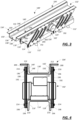
Fig. 3 is a perspective view of another embodiment of a vibratory apparatus having a single deck; -
Fig. 4 is a rear end view of the vibratory apparatus ofFig. 3 ; -
Fig. 5 is a side view of an embodiment of a vibratory apparatus having multiple decks; -
Fig. 6 is a rear end view of the vibratory apparatus ofFig. 5 ; -
Fig. 7 is a perspective view of an embodiment of a vibratory apparatus having a spiral deck; and -
Fig. 8 is a plan view of the vibratory apparatus ofFig. 7 . - A single deck conveyor according to embodiments of the present disclosure is illustrated in
Figs. 1-4 . - The embodiment of a
single deck apparatus 100 ofFigs. 1 and 2 is a two-mass vibratory apparatus, including a first mass (or exciter) 102 and a second mass (or trough) 104. Connected between thefirst mass 102 and thesecond mass 104 are a number of resilient members 106 (or reactor springs), which are formed from structural elements of theapparatus 100. While the embodiment of thesingle deck apparatus 100 ofFigs. 1 and 2 is a two-mass feeder, the embodiments of this disclosure are not limited to feeders, but may be applicable to other types of vibratory apparatuses, such as conveyors, screens, shakeouts and the like. - The
exciter 102 may include abase 110 that is supported on a reference surface. In particular, thebase 110 may be supported on the reference surface byresilient members 112, such as coil springs or marshmallow springs, which resilient members orsprings 112 may also be referred to as isolation members or springs. According to certain embodiments, the isolation members may be simply rubber pads. For the reasons provided below, theisolation springs 112 even may be omitted from embodiments of thepresent apparatus 100. - As best seen in
Fig. 1 , thebase 110 may include aplatform 114 and first andsecond side walls platform 114 along opposing edges of theplatform 114. Theplatform 114 extends from a first end to a second end, and theside walls platform 114, although theside walls - The
side walls exciter 102 to thetrough 104 as explained below. - The remainder of the
exciter 102 is coupled, mounted or supported on theplatform 114. Theexciter 102 further includes ashaft 120 with a shaft axis 122 (seeFig. 1 ) that is disposed coupled to theplatform 114, and may extend transverse to the path of travel along thetrough 104, further comprising one or more eccentric oreccentric weights 124 coupled to theshaft 120. According to certain embodiments, theshaft 120 is the shaft of anelectric motor 126, which motor is coupled 126 (e.g., by fasteners) to theplatform 114. According to other embodiments, theshaft 120 is coupled to a shaft of an electric motor, which motor is mounted off the apparatus (e.g., to the side of the apparatus). - It will be recognized that according to other embodiments, the
exciter 102 may include a plurality of shafts, each with eccentric weights mounted thereon, with each of the shafts being defined by one of a plurality of motors. In addition, the motor (or motors) 126 may be electrically coupled to a controller 128 (seeFig. 2 ), whichcontroller 128 may include a microprocessor and memory. Thecontroller 128 may be configured (e.g., programmed) to control the operation of the motor 126 (and thus the shaft 120) to vary the motion of the material on thetrough 104. - The
trough 104 includes adeck 130, and to the extent thetrough 104 is connected to theexciter 104 by theresilient members 106, it may be said that thedeck 130 is connected to theexciter 104 by theresilient members 106. Thedeck 130 has afirst end 132 and asecond end 134, and material may be moved along thedeck 130 with a path of travel between a first point and a second point, e.g., between the first andsecond ends deck 130 may have opposing surfaces, which for ease of illustration may be referred to as a first, or top,surface 136 and a second, or bottom, surface 138 (seeFig. 1 ). - The
top surface 136 of thedeck 130 may be treated or may have one or more protective layers disposed thereon to protect thedeck 130 as material is moved between the first andsecond ends deck 130 may have openings or passages that extend between thesurfaces top surface 136 of thedeck 130. Separation of materials may also be achieved with adeck 130 that is defined by spaced structures, such as fingers, that define openings between them and permit the passage of certain materials through the openings while retarding the passage of other materials therethrough. - In the illustrated embodiment, the
first end 132 of thedeck 130 is at substantially the same elevation as thesecond end 134 of thedeck 130 relative to a reference surface (i.e., the deck is horizontal). The reference surface may be defined by a foundation, which in turn may be the ground story of a building or an upper story of such a structure. According to other embodiments, thefirst end 132 of thedeck 130 may be above or below thesecond end 134 of the deck 130 (i.e., thedeck 130 is tilted or sloped, for example to allow gravity to assist or retard motion of material along the deck 130). - The
trough 104 also includes afirst side wall 140 and asecond side wall 142 extending or depending from thefirst end 132 to thesecond end 134, although theside walls first end 132 to thesecond end 134. The first andsecond side walls surface 136 of thedeck 130 define an open-topped volume (although according to certain embodiments, thetrough 104 may also include a hood that closes or covers the open top). For example, thefirst side wall 140 has an inner-facingsurface 144, and thesecond side wall 142 has an inner-facingsurface 146, and the inner-facingsurface 144 of thefirst side wall 140 faces (or opposes) the inner-facingsurface 146 of the second side wall142. - The
deck 130 is disposed between the first andsecond side walls 140, 142 (as illustrated) and is coupled to the first andsecond side walls deck 130 is said to be coupled to theside walls side walls deck 130 is connected to the cross-members). As illustrated inFig. 1 , thedeck 130 has afirst edge 148 that is coupled to the first side wall 140 (specifically, the inner-facing surface 144) and asecond edge 150 that is coupled to the second side wall 142 (specifically, the inner-facing surface 146). - As also illustrated, the
deck 130 is integrally connected to the first andsecond side walls deck 130 and first andsecond side walls deck 130 andside walls deck 130 andside walls apparatus 100. - While the illustrated embodiment includes a
deck 130 that defines a straight path between the first and second ends 132, 134, it is possible that thedeck 130 be curved instead. To this end, theside walls deck 130 to the curved path, although the materials may move along thedeck 130 in a curved path without the need to includecurved side walls - The
apparatus 100 also includes a plurality ofplates 170 disposed to a first side and a second side of thedeck 130. Aplate 170 is a thin sheet of metal or other material, which may be flat or two-dimensional in quality (i.e., planar) or may be shaped (e.g., curved) to be three-dimensional in quality. Where theplate 170 is three-dimensional, theplate 170 retains a thickness that is considerably smaller in dimension that the length and/or width of theplate 170. As illustrated, fourplates 170 are arranged about theapparatus 100, one pair at thefirst end 132 and one pair at thesecond end 134 with oneplate 170 of each pair disposed on either the first side or the second side of the deck 130 (and thus the trough 104). - The
plates 170 are joined at afirst end 172 to the exciter 102 (and in particular to one of theside walls 116, 118) and at asecond end 174 to the trough 104 (and in particular to one of theside walls 140, 142). Theplates 170 are joined to theexciter 102 and thetrough 104 with fasteners (e.g., bolts/nuts, rivets, etc.), for example. The connection of theplates 170 to thesides deck 130 as illustrated may provide for a better transfer of forces between theexciter 102 and thetrough 104, as the fastener (e.g. bolts) which may be used to jointrough 104,exciter 102, andplates 170 together may perform better under the shear conditions created than in the compression/tension cycling created, for example, when slats are used and arranged transverse to thetrough 104. In addition, a spacer may be disposed between theplates 170 and theexciter 102 or thetrough 104. In particular, these spacers may be disposed between thefirst end 172 and theside walls base 110 and thesecond end 174 and theside walls trough 104. - As illustrated, the
plates 170 have at least oneopening 176 formed in through theplate 170. Theopening 176 defines a plurality ofwebs 178 that join theexciter 102 to thetrough 104. Thesewebs 178 have a thickness that is disposed transverse to the path of travel of material along thedeck 130 between thefirst end 132 and thesecond end 134. The thickness of thewebs 178 is considerably smaller in dimension that the length and/or width of theplate 170. Thewebs 178 define the plurality of resilient members or springs 106 coupled between thetrough 104 and base 110 (and thus the exciter 102). - As is also illustrated, the embodiment of
Figs. 1 and 2 hasplates 170 with threeopenings 176 each. While other embodiments may use other shapes, each opening 176 of this embodiment is of a generally oval shape, having amajor axis 180. The threeopenings 176 are arranged on theplate 170 with two of the openings disposed to the right and the left (as illustrated inFig. 2 ) of a central opening. Themajor axes 180 of the threeopenings 176 are parallel to each other. The threeopenings 176 define twowebs 178 on either side of the central opening, and twoadditional webs 178, one to the left of the leftmost opening and one to the right of the rightmost opening. Thewebs 178 have longitudinal axes between first and second ends 182, 184 that are substantially parallel to themajor axes 180 of theopenings 176. - The removal of the material from the
plate 170 defines an embodiment withwebs 178 that have a width in the plane of theplate 170 that is comparable in dimension to the thickness in the direction transverse to the path of travel of material along the deck 130 (although other embodiments may have other dimensions). Consequently, each of thewebs 178 thus formed is substantially smaller in thickness and width than in length (i.e., the dimension in the direction along the longitudinal axis of theweb 178 between theends 182, 184). In addition, because of the oval shape of theopenings 176, the illustratedwebs 178 have ends 182, 184 that are larger in width than at the midpoint of thewebs 178. In fact, as illustrated, theends web 178, although that may not be true of other embodiments. It fact, it will be recognized that the thickness of theplate 170 may be varied relative to aweb 178 having a common (or identical) width to achieve certain spring characteristics, which could result in a family of springs with similar shape but differing spring rates. In addition or in the alternative, the web width may be varied to vary the spring characteristics, such as resultant rocking frequencies. - As is illustrated, each of the
openings 176 andwebs 178 is disposed at an angle to the path of travel of the materials along thedeck 130 between thefirst end 132 and thesecond end 134. For example, theaxes 180 are disposed at an angle to the path of travel of the materials along thedeck 130, and similarly the longitudinal axes of thewebs 178 between theends openings 176 and thewebs 178 need not be the same for other embodiments. For example, according to certain embodiments, theopenings 176 andwebs 178 may be oriented generally upright (i.e., perpendicular to the deck 130). - In the embodiment of
Figs. 1 and 2 , thewebs 178 are generally of the same shape between theends webs 178 formed by theopenings 176 may have different shapes, such that eachindividual web 178 may even have a different shape. However, certain advantages may be associated with aplate having webs 178 of a similar size and shape as illustrated. - The use of
resilient members 106 in the form ofwebs 178 formed from theplates 170 may provide one or more of the following advantages. - Where the resilient member is not in the form of a coil spring, it is not necessary to limit the material selection according to the requirements of coil spring fabrication. Consequently, materials that might not be fabricated easily into a coil spring, such as stainless steel, may be used for the resilient members in the form of
webs 178. The use of stainless steel is particularly advantageous where theapparatus 100 is intended to meet a food-grade specification. - The
webs 178 can be fashioned to provide a variety of stroke and spring rate characteristics based not only on the material selection, but also based on the amount of material removed/remaining (i.e.,openings 176/webs 178). Consequently, a greater range of strokes and spring rates may be accommodated than may be the case with coil springs, which are conventionally manufactured in a standard set of sizes/rates. In fact, the greater range of strokes and spring rates possible provides for greater facility to customize aparticular apparatus 100 to meet a customer's specific needs. - The manufacturing methods used to form
openings 176 in theplates 170 may also be much simpler than the methods used to form coil springs. Forming the openings 176 (e.g., burning) in theplates 170 may also be more economically efficient and cost less. - In addition, the use of resilient members in the form of
webs 178 permits theexciter 102 to provide high frequency (e.g., kHz range and above, or more particularly above 3600 Hz) vibration. Operation that provides high frequency, low stroke has a number of advantages. - High frequency vibration, for example, is better in certain applications, such as fines screening, and has a tendency to fluidize material and cause piled material to spread. High frequency may also be beneficial for use in conveying materials that are more fragile. High frequency operation may also lead to lower noise levels.
- On the other hand, low stroke operation involves small dynamic forces. Consequently, the
apparatus 100 can be disposed directly on the foundation without special requirements (e.g., without isolation springs 112), other than accepting the static load of the machine. Alternatively, the mechanism used for isolation may be much simpler (e.g., rubber pads). Further, the transfer points on and off theapparatus 100 require very little clearance, with smoother start up and shut down and lower risk of injury to the operator. This in turn may lead to a lesser potential for accidents to occur around the transfer points. Low stroke operation may also have advantages when conveying fragile materials. - While the stroke and spring rate may be varied through the selection of materials and amount of material removed/retained to form the webs, according to the invention, at lest one
additional plate 170 is added. These plates, like theplates 170, have openings formed therethrough to define a particular stroke and spring rate. The plates are also mounted with their thickness transverse to the path of travel. The additional plates are mounted outwardly from the first set of plates170. -
Figs. 3 and 4 illustrate the embodiment according to the invention wherein multiple plates are included. Because this embodiment is similar in structure to that ofFig. 1 and 2 , those elements in common with the first embodiment are numbered similarly, except that those of the embodiment ofFigs. 3 and 4 are denoted with a prime. While two sets of plates are illustrated in the embodiment ofFigs. 3 and 4 , it will be understood that additional sets of plates (e.g., three, four or more sets) may be used in a particular embodiment. - As seen in
Fig. 3 , the apparatus 100' includes an exciter 102' and a trough 104'. Similar to the embodiment ofFigs. 1 and 2 , the exciter 102' includes a base 110' supported on isolation springs 112', the base 110' having a platform 114' with side walls 116', 118', and a motor 126' with shaft 120' with eccentric weights 124' disposed on the base 110' (and in particular the platform 114'). The trough 104' has a deck 130' and side walls 140', 142', the side walls 140', 142' coupled to the side edges 148', 150' of the deck 130'. The motor 126' may be coupled to a controller (not shown) as illustrated inFig. 2 . - As illustrated in
Fig. 3 but better visualized inFig. 4 , the apparatus 100' also includes a set ofinner plates 190 and a set ofouter plates 192 disposed transversely outwardly from theinner plates 190. Theinner plates 190 include afirst end 194 that is coupled to one of the side walls 116', 118', and asecond end 196 that is coupled to one of the side walls 140', 142'. Similarly, theouter plates 192 include afirst end 198 that is coupled to one of the side walls 116', 118', and asecond end 200 that is coupled to one of the side walls 140', 142'. Theplates inner plates 190 and theouter plates 192. - The
inner plates 190 andouter plates 192 haveopenings webs Fig. 3 . As illustrated, theinner plates 190 and theouter plates 192 haveopenings respective plate plate webs individual plates - According to other embodiments, the
openings plate plate webs plates individual plates plates plates openings plates plates - As can be seen in
Fig. 4 , theplates spacers 210 that are disposed between thefirst end 194 of theinner plates 190 and the side walls 116', 118' of the base 110', andspacers 212 are disposed between thesecond end 196 of theinner plates 190 and the side walls 140', 142' of the trough 104' (i.e., to either side of the deck 130'). In a similar fashion,spacers 214 are disposed between the first ends 194, 198 of theplates spacers 216 are disposed between the second ends 196, 200 of theplates - According to still another embodiment, one or more of the plates may be formed as a single piece (i.e., integrally) with the side walls of the
base 110, 110' (and thus theexciter 102, 102'). Such an embodiment would eliminate the need to fasten the first ends of the plates (and the first ends of the webs) to the side walls of thebase 110, 110'. According to still another embodiment, one or more of the plates may be formed as a single piece (i.e., integrally) with the side walls of thetrough 104, 104'. Such an embodiment would eliminate the need to fasten the second ends of the plates (and the second ends of the webs) to the side walls of thetrough 104, 104'. In fact, a single embodiment may have the plates formed as a single piece with the side walls of thebase 110, 110' and the side walls of thetrough 104, 104'. - A linear,
multi-deck apparatus 250 according to embodiments of the present disclosure is illustrated inFigs. 5 and 6 . This embodiment also illustrates an embodiment that would be structurally and operationally similar to the one-deck apparatuses 100, 100' if theplates base 110, 110' and thetrough 104, 104'. - The embodiment of a
multi-deck apparatus 250 ofFigs. 5 and 6 is a two-mass vibratory apparatus, including afirst mass 252 and asecond mass 254. Connected between thefirst mass 252 and thesecond mass 254 are a number of resilient members 256 (or reactor springs), which are formed from structural elements of theapparatus 250. - Each
mass trough trough deck second deck 264 is above, or at a higher elevation than thefirst deck 262 relative to a reference surface. The reference surface may be defined by a foundation, which in turn may be the ground story of a building or an upper story of such a structure. As such, thesecond deck 264 may be referred to as thetop deck 264, and thefirst deck 262 may be referred to as thebottom deck 262. - Each
deck first end second end deck deck surface surface apparatus 250 inFigs. 5 and 6 . - As was the case above, the
top surfaces decks deck deck surfaces top surfaces decks deck 264 may have openings or passages, while thedeck 262 does not; alternatively, thedeck 264 may have openings or passages of a particular size or shape, and thedeck 262 may have openings or passages of a different size or shape, such that one size of materials passes alongdeck 264, a smaller sized material passes alongdeck 262, and a still smaller sized material passes through thedeck 262. - In the illustrated embodiment, the first ends 266, 268 of the
decks second end decks first end deck second end deck 262, 264 (i.e., thedeck deck 262, 264). Further, it is not necessary that the slope or inclination of thedeck 262 be the same or in the same direction as that of thedeck 264. - The
trough 258 may also include afirst side wall 282 and asecond side wall 284 extending or depending from thefirst end 266 to thesecond end 270, although not all embodiments of theapparatus 250 necessarily requiresuch side walls 282, 284 (e.g., theside walls first end 266 to the second end 270). The first andsecond side walls surfaces surface 274 of thedeck 262 and thesurface 280 of thedeck 264 define an closed-topped volume. - The
trough 260 may also include afirst side wall 292 and asecond side wall 294 extending or depending from thefirst end 268 to thesecond end 272, although theside walls first end 268 to thesecond end 272. The first andsecond side walls surfaces surface 276 of thedeck 264 define an open-topped volume (although other embodiments may include a hood. - The
decks second side walls second side walls decks side walls deck 262 has afirst edge 300 that is coupled to the first side wall 282 (specifically, the inner-facing surface 286) and asecond edge 302 that is coupled to the second side edge 284 (specifically, the inner-facing surface 288). Similarly, thedeck 264 has afirst edge 304 that is coupled to the first side wall 292 (specifically, the inner-facing surface 296) and asecond edge 306 that is coupled to the second side edge 294 (specifically, the inner-facing surface 298). - As illustrated in
Fig. 5 , theapparatus 250 also includes ashaft 310 which may be disposed transverse to the path of travel along thetroughs shaft 310 is coupled to themass 252, and particularly thesurface 278 of thedeck 262, and one or more eccentric oreccentric weights 314 are coupled to theshaft 310. It will be recognized that an alternative arrangement, not forming part of the present invention, would be for the assembly ofshaft 310 andweights 314 to be coupled instead to themass 254, as either option is acceptable. According to certain embodiments, theshaft 310 is the shaft of anelectric motor 316, which motor 316 is coupled (e.g., by fasteners) to thedeck 264. According to other embodiments, theshaft 310 is coupled to a shaft of an electric motor, which motor is mounted off the apparatus (e.g., to the side of the apparatus 250). Theshaft 310,weights 314 andmotor 316 have been omitted fromFig. 6 to simplify the discussion of certain other elements of theapparatus 250. - According to other embodiments, a plurality of shafts may be used, each with eccentric weights mounted thereon, with each of the shafts being defined by one of a plurality of motors. In addition, the
motor 316 may be electrically coupled to acontroller 318, whichcontroller 318 may include a microprocessor and memory. Thecontroller 318 may be configured (e.g., programmed) to control the operation of the motor 316 (and thus the shaft 310) to vary the motion of the material on thedecks masses ends 270, 272). - As illustrated, in an example not forming part of the invention, the
side walls side walls single plate second plates openings 324 formed in through theplates openings 324 may be generally disposed along a linear path from the first ends 266, 268 of thedecks decks openings 324 may be disposed such that the openings are formed in theplates second deck sections plates 320, 322 (and thus theside walls - The
openings 324 define a plurality ofwebs 326 that join the portion of thefirst side wall 282 andsecond side wall 284 supporting thefirst deck section 262 with the portions of thefirst side wall 292 andsecond side wall 294 supporting thesecond deck section 264. Thesewebs 326 have a thickness that is disposed transverse to the path of travel of material along thedecks second end webs 326 may also have a width that is comparable to their thickness, both of which dimensions are smaller than the length of thewebs 326 from one end of the web to the other. In fact, much of the discussion above relative to thewebs 178 applies with equal force to thewebs 326. - The
webs 326 thus define a plurality of resilient members or springs coupled between theside wall portions first deck section 262 and theside wall portions second deck section 264. Alternatively, theside wall portions first deck section 262 may be referred to as the first tier, and theside wall portions second deck section 264 may be referred to as the second tier. As such, thewebs 326 may be described as being coupled to the first tier at afirst end 328 and the second tier at asecond end 330. - While an embodiment having a first and second tier has been illustrated, it will be recognized that other embodiments of the conveyor according to the present disclosure may include additional decks defining additional tiers (e.g., third, fourth, fifth and sixth tiers). According to such embodiments, the plurality of webs may be disposed between the first and second tiers, such that the first tier defines the first mass and the second through sixth tiers define the second mass. As one alternative, the webs may be defined between the third and fourth tiers, such that the first, second, and third tiers define the first mass, and the fourth, fifth and sixth tiers define the second mass. Other alternatives are possible.
- According to the invention, additional plates are attached outside the side walls of an apparatus, such as illustrated in
Figs. 5 and 6 , to vary the spring characteristics. In this regard, the additional plates may be added as is illustrated in the embodiment ofFigs. 3 and 4 , except that the inner set of plates would be defined by the side walls having openings therethrough to define the webs acting as springs, such as is illustrated inFigs. 5 and 6 . The outer set of plates may not depend or extend to the top and bottom of the side walls, but may be located only in that region of the apparatus that substantially overlies the webs formed in the side walls of the apparatus. - For that matter, it may be possible to design a multi-tier apparatus wherein the first and second tiers are coupled to plates, such as are illustrated in
Figs. 1-4 , that are in turn secured to side walls, instead of forming the webs from plates that are formed as one piece (i.e., integrally) with the side walls. - The multi-deck or multi-tier embodiments of
Figs. 5 and 6 are linear between the opposing ends. On the other hand, multi-tier embodiments may be defined for an apparatus having a curved deck. Certain multi-tier embodiments may be defined for an apparatus having a spiral deck. Preferably, the spiral deck has a continuous (or substantially continuous) deck between an inlet end and an outlet end. - A
spiral conveyor 350 is illustrated inFigs. 7 and 8 . Spiral conveyors are often used to heat or cool work pieces or granular material. For example, red-hot castings (which may have a temperature of approximately 1000 degrees F. or more) are fed into the spiral conveyor. Cool air is directed over the castings as the castings travel up the spiral, thereby to reduce the temperature of the castings. - The
spiral conveyor 350 includes acurved deck 352 that extends between afirst end 354 and asecond end 356. In particular, thecurved deck 352 may have a spiral shape, and thus theconveyor 350 may be referred to as a spiral conveyor. As used herein, spiral includes helical and helicoid shapes. - The
curved deck 352 may have opposing surfaces, which for ease of illustration may be referred to as a first, or top,surface 360 and a second, or bottom,surface 362. In operation, material may move in a curved path of travel over thetop surface 360 of thespiral deck 352 between thefirst end 354 and thesecond end 356 of thedeck 352. Thetop surface 360 of thespiral deck 352 may be treated or may have one or more protective layers disposed thereon to protect thedeck 352 as material is moved between the first and second ends 354, 356. - As material follows a curved path of travel along the
spiral deck 352, the elevation of the material may increase or decrease relative to a reference surface. The reference surface may be defined by a foundation, which in turn may be the ground story of a building or an upper story of such a structure. As illustrated, thespiral deck 352 may increase in elevation from thefirst end 354 to thesecond end 356, such that afirst deck section 370 may be disposed below asecond deck section 372 relative to the reference surface on which thespiral conveyor 350 is disposed. As illustrated, thefirst end 354 of thedeck 352 may be designated the lowest point or elevation, while thesecond end 356 of thedeck 352 may be designated the highest point or elevation. - As illustrated, the
first deck section 370 is joined to thesecond deck section 372 to form a substantially continuous surface between thefirst end 354 and thesecond end 356 of thedeck 352. Moreover, given the increasing elevation ofsuccessive deck sections Figs. 1 and 2 , thetop surface 360 of thefirst section 370 faces thebottom surface 362 of thesecond section 372. - A
shaft 380 witheccentric weights 382 mounted on theshaft 380 is coupled to thefirst section 370. Theshaft 380 may be defined by amotor 384, similar to the embodiments illustrated inFigs. 1-6 . While only one assembly ofshaft 380,weights 382, andmotor 384 is illustrated, multiple assemblies will likely be mounted to thefirst section 370. According to certain embodiments, the action of the assembly ofshaft 380,weights 382, andmotor 384 moves material, such as work pieces (e.g., hot castings), from thefirst end 354 to the second end 356 (i.e., upward or vertically upward). According to other embodiments, the assembly/assemblies may cause material to move along thetop surface 360 of thespiral deck 352 from thesecond end 356 to thefirst end 354, so that the material is conveyed vertically downward along thespiral deck 352. - The
spiral deck 352 may be coupled to aframe 390 that is supported on the reference surface. In particular, theframe 390 may be supported on the reference surface byresilient members 392, such as coil springs or marshmallow springs, which resilient members or springs 392 may also be referred to as isolation members or springs. However, thesprings 392 may be omitted according to other embodiments, and are considered optional in the illustrated embodiment. - The
frame 390 may include a cylindricalinner wall 394 and a cylindricalouter wall 396. The cylindricalinner wall 394 may have a first diameter, and the cylindricalouter wall 396 may have a second diameter. The first diameter may be smaller than the second diameter, such that theinner wall 394 may be disposed within theouter wall 396. As illustrated, theinner wall 394 and theouter wall 396 may have a common center, although this need not be the case according to all embodiments. - The
inner wall 394 and theouter wall 396 have inner-facing and outer-facing surfaces. For example, theinner wall 394 has an inner-facingsurface 398 and an outer-facingsurface 400, and theouter wall 396 has an inner-facingsurface 402 and an outer-facingsurface 404. As illustrated, the inner-facingsurface 402 of theouter wall 396 faces the outer-facingsurface 400 of theinner wall 394. - The
spiral deck 352 may have aninner edge 406 and anouter edge 408, theinner edge 406 being closer to the center in a radial direction than the outer edge 408 (alternatively, theouter edge 408 is further from the center in a radial direction than the inner edge 406). According to certain embodiments, a diameter taken at theinner edge 406 may be greater than or equal to the first diameter of the cylindricalinner wall 394, and a diameter taken at theouter edge 408 may be less than or equal to the second diameter of the cylindricalouter wall 396. - The
spiral deck 352 is disposed between and coupled to theinner wall 394 and theouter wall 396. - According to certain embodiments, the spiral deck may be coupled to the inner and
outer walls inner edge 406 of thespiral deck 352 is joined to the outer-facingsurface 400 of theinner wall 394, and theouter edge 408 of thespiral deck 352 is joined to the inner-facingsurface 402 of theouter wall 396. Theedges edges edges 406, 480 may be coupled to thesurfaces U.S. Pat. No. 7,296,951 . - According to the illustrated embodiment in
Fig. 8 , the inner andouter edges spiral deck 352 are spaced from the inner andouter walls inner edge 406 of thedeck 352 is spaced from the outer-facingsurface 400 of theinner wall 394, and theouter edge 408 of thedeck 352 is spaced from the inner-facingsurface 402 of theouter wall 396 to form afirst gap 410 between the inner edge/outer-facingsurface second gap 412 between the outer edge/inner-facingsurface first end 416 to theinner wall 394 and at asecond end 418 to theouter wall 396, and thebottom surface 362 of thespiral deck 352 may be disposed on the cross-supports 414. In fact, thebottom surface 362 of thespiral deck 352 may be directly connected (e.g., with fasteners) to the cross-supports 414. According to such an embodiment, guide rails may be disposed at the inner andouter edges spiral deck 352. - As illustrated, the inner and
outer walls openings 420 formed in through the inner andouter walls 394, 396 (of which only theopenings 420 in theouter wall 396 are visible inFig. 7 ). The plurality ofopenings 420 may be formed generally along a curved or spiral path through the inner andouter walls openings 420 may be disposed such that theopenings 420 are formed in the inner andouter walls second deck sections outer walls - The
openings 420 define a plurality ofwebs 422 that join the portion of theinner wall 394 andouter wall 396 supporting thefirst deck section 370 with the portions of theinner wall 394 andouter wall 396 supporting thesecond deck section 372. Thesewebs 422 have a thickness that is disposed transverse to the path of travel of material along thecurved deck 352 between thefirst end 354 and thesecond end 356 that is much smaller than the length and width of thewalls webs 422 may also have a width that is comparable to their thickness, both of which dimensions are smaller than the length of thewebs 422 from one end of the web to the other. In fact, much of the discussion above relative to thewebs 178 applies with equal force to thewebs 422. - The
webs 422 thus define a plurality of resilient members or springs coupled between portions or sections of the inner andouter wall first deck section 370 and the portions or sections of inner andouter wall second deck section 372. SeeFig. 7 . Furthermore, the inner andouter wall first deck section 370 may be referred to as the first tier, and the inner andouter wall second deck section 372 may be referred to as the second tier. In particular, the first and second tier may be defined such that the length of the path of travel from thefirst end 354 to the junction between the first and second tiers is the same as the junction between the first and second tiers and thesecond end 356. As such, thewebs 422 may be described as being coupled to the first tier at a first end 424 and the second tier at asecond end 426. - According to such embodiments, the shafts/
weights outer walls spiral deck 352 and connecting the shafts/weights weights - While an embodiment having a first and second tier has been illustrated, it will be recognized that other embodiments of the spiral conveyor according to the present disclosure may include additional tiers (e.g., third, fourth, fifth and sixth tiers). According to such embodiments, the plurality of webs may be disposed between the first and second tiers, such that the first tier defines the first mass and the second through sixth tiers define the second mass. As one alternative, the webs may be defined between the third and fourth tiers, such that the first, second, and third tiers define the first mass, and the fourth, fifth and sixth tiers define the second mass. Other alternatives are possible.
- A vibratory conveyor according to the above embodiments thus may provide one or more of the following advantages, some of which also may have been mentioned above. The cost of using resilient members in the form of webs, such as may be formed by forming an opening in a plate or side wall, may be much less than the cost of using coil springs, which are formed using a more complicated manufacturing process. In addition, materials may be used for the resilient members in the form of webs that are not suitable for use in coil springs, such as stainless steel. The resilient members in the form of webs both provide a particular spring rate and limit the direction of the motion, and consequently provide a reduced cost relative to apparatuses using coil springs, because a leg or linkage is required in such coil spring installations to limit the direction of motion and the additional equipment increases the overall cost. The resilient members in the form of webs disposed as the sides of the apparatus (i.e., parallel to the direction of motion instead of transverse) permit a less complicated, costly installation and limit or eliminate the localized stresses involved with the use of slat springs. According to the invention, the resilient member comprises at least one additional plate, which is disposed outside of the bulk of the apparatus. The at least one additional plate may be used to vary spring characteristics. When used as a two-mass vibratory apparatus, a smaller motor may be used than with vibratory apparatuses using a brute force arrangement with the motor directly driving the trough. The two-mass arrangement may also provide better load response and smoother start and stop, while still providing high frequency performance. In addition, brute force apparatuses can be limited in length by the effect of vertical deflections. The spring according to the present disclosure enables a design better able to distribute driving forces down the length of the unit. This may reduce cantilever length, unintended deflections, and stress making it possible to design longer high frequency units
- While certain equipment has been described relative to the illustrated embodiments, additional equipment could be included as well. For example, relative to the spiral conveyor, the cross-members 414 may be hollow and fitted with one or more nozzles. Cooling air, generated by a fan for example, may be passed through the hollow cross-members and nozzles, and directed on the material passing along the deck to cool the material. See, e.g.,
U.S. Pat. No. 7,540,694 . The spiral conveyor also be configured to provide a fines collection system, such as also is described inU.S. Pat. No. 7,540,694 . - Although the preceding text sets forth a detailed description of different embodiments of the invention, it should be understood that the legal scope of the invention is defined by the words of the claims set forth at the end of this patent. The detailed description is to be construed as exemplary only and does not describe every possible embodiment of the invention since describing every possible embodiment would be impractical, if not impossible. Numerous alternative embodiments could be implemented, using either current technology or technology developed after the filing date of this patent, as long as they are within the scope defined by the appended claims.
- It should also be understood that, unless a term is expressly defined in this patent using the sentence "As used herein, the term '_' is hereby defined to mean..." or a similar sentence, there is no intent to limit the meaning of that term, either expressly or by implication, beyond its plain or ordinary meaning, and such term should not be interpreted to be limited in scope based on any statement made in any section of this patent (other than the language of the claims). To the extent that any term recited in the claims at the end of this patent is referred to in this patent in a manner consistent with a single meaning, that is done for sake of clarity only so as to not confuse the reader, and it is not intended that such claim term be limited, by implication or otherwise, to that single meaning.
Claims (3)
- A vibratory apparatus (100) comprising:a first mass (102) having a platform (114);a second mass (104) having a deck (130) with a path of travel between a first point (132) and a second point (134) along the deck (130),at least one resilient member (106) in the form of a plate (170) having a thickness, the plate (170) coupled at a first end (172) to the first mass (102) and at a second end (174) to the second mass (104) with the thickness disposed transverse to the path of travel along the deck (130), the plate (170) having at least one opening (176) formed therethrough to form a web (178) having a spring characteristic;wherein the platform (114) has side walls (116, 118) and the second mass (104) has side walls (140, 142) coupled to either side of the deck (130),characterized in that it further comprisesa shaft (120) coupled to the platform (114), the shaft (120) having at least one eccentric weight (124) coupled thereto; anda motor (126) coupled to the shaft; whereinthe at least one resilient member (106) comprises at least two plates (170) comprising an inner plate (190) and an outer plate (192) disposed transversely outwardly from the inner plate (190),the inner plate (190) and the outer plate (192) each having a first end (194, 198) coupled to one of the side walls (116, 118) of the platform (114) of the first mass (102) and a second end (196, 200) to one of the side walls (140, 142) of the second mass (104) with the thickness disposed transverse to the path of travel along the deck (130),each plate (190, 192) having at least one opening (202, 204) formed therethrough to form a web (206, 208) having a spring characteristic.
- The vibratory apparatus (100) according to claim 1, wherein the plates (190, 192) have a plurality of openings (202, 204) formed therethrough to form a plurality of webs (206, 208).
- The vibratory apparatus (100) according to claim 2, wherein the openings (202, 204) and the webs (206, 208) are disposed at an angle to the deck (130).
Applications Claiming Priority (2)
| Application Number | Priority Date | Filing Date | Title |
|---|---|---|---|
| US15/432,564 US10046916B1 (en) | 2017-02-14 | 2017-02-14 | Vibratory apparatus with structural resilient member |
| PCT/US2017/068763 WO2018151796A1 (en) | 2017-02-14 | 2017-12-28 | Vibratory apparatus with structural resilient member |
Publications (2)
| Publication Number | Publication Date |
|---|---|
| EP3582907A1 EP3582907A1 (en) | 2019-12-25 |
| EP3582907B1 true EP3582907B1 (en) | 2025-02-19 |
Family
ID=61018024
Family Applications (1)
| Application Number | Title | Priority Date | Filing Date |
|---|---|---|---|
| EP17832874.6A Active EP3582907B1 (en) | 2017-02-14 | 2017-12-28 | Vibratory apparatus with structural resilient member |
Country Status (5)
| Country | Link |
|---|---|
| US (2) | US10046916B1 (en) |
| EP (1) | EP3582907B1 (en) |
| DK (1) | DK3582907T3 (en) |
| ES (1) | ES3027569T3 (en) |
| WO (1) | WO2018151796A1 (en) |
Families Citing this family (4)
| Publication number | Priority date | Publication date | Assignee | Title |
|---|---|---|---|---|
| US10046916B1 (en) * | 2017-02-14 | 2018-08-14 | General Kinematics Corporation | Vibratory apparatus with structural resilient member |
| EP3947213A4 (en) | 2019-04-05 | 2023-01-04 | Blue Sky Ventures (Ontario) Inc. | VIBRATING CONVEYOR FOR CONVEYING ARTICLES, MACHINE AND RELATED FILLING METHODS |
| WO2020236821A1 (en) * | 2019-05-20 | 2020-11-26 | General Kinematics Corporation | Vibratory drum with circular motion |
| IT202100013355A1 (en) * | 2021-05-24 | 2022-11-24 | Brovind Vibratori S P A | DOUBLE MASS VIBRATORY CONVEYOR UNIT AND VIBRATION DAMPER KIT FOR A DOUBLE MASS VIBRATORY CONVEYOR UNIT. |
Family Cites Families (21)
| Publication number | Priority date | Publication date | Assignee | Title |
|---|---|---|---|---|
| US2901110A (en) | 1955-12-06 | 1959-08-25 | Ajax Flexible Coupling Co Inc | Vibratory conveyors |
| US3575620A (en) * | 1970-03-18 | 1971-04-20 | Illinois Tool Works | Vibratory drive unit |
| US4007825A (en) | 1975-08-05 | 1977-02-15 | Fmc Corporation | Vibratory parts feeder driven by rotating eccentric weights |
| US4795025A (en) * | 1985-06-28 | 1989-01-03 | Kabushiki Kaisha Toshiba | Parts feeding apparatus of the piezoelectric drive type |
| DE3713979C2 (en) | 1987-04-25 | 1996-08-29 | Vossloh Schwabe Gmbh | Vibratory conveyor |
| DE3713980A1 (en) * | 1987-04-25 | 1988-11-03 | Schwabe Gmbh | VIBRATING CONVEYOR |
| US5024320A (en) | 1987-05-08 | 1991-06-18 | General Kinematics Corporation | Vibratory spiral elevator |
| US5131525A (en) | 1989-10-17 | 1992-07-21 | General Kinematics Corporation | Vibratory conveyor |
| US5934446A (en) | 1997-06-05 | 1999-08-10 | General Kinematics Corporation | Bi-directional vibratory conveyor |
| US6029796A (en) | 1997-08-26 | 2000-02-29 | General Kinematics Corporation | Two way vibratory conveyor |
| US6155404A (en) | 1999-06-18 | 2000-12-05 | General Kinematics Corporation | Vibratory conveyors |
| US6298200B1 (en) * | 1999-11-19 | 2001-10-02 | Eastman Kodak Company | Exposure count indicator for camera |
| US6298978B1 (en) | 2000-05-01 | 2001-10-09 | Carrier Vibrating Equipment, Inc. | Reversing natural frequency vibratory conveyor system |
| CN1380234A (en) * | 2001-04-06 | 2002-11-20 | 神钢电机株式会社 | Piezoelectric driving vibratory feeder and piezoelectric element driving feeder |
| DE60330597D1 (en) | 2002-12-23 | 2010-01-28 | Gen Kinematics Corp | BENDING VIBRATION CONVEYOR |
| TW200508117A (en) * | 2003-01-14 | 2005-03-01 | Shinko Electric Co Ltd | Piezoelectric part feeder |
| US7296951B2 (en) | 2004-08-25 | 2007-11-20 | General Kinematics Corporation | Vibratory spiral conveyor |
| US7296694B2 (en) * | 2004-10-12 | 2007-11-20 | Weymouth Bret M | Tower-type grease removal apparatus for commercial grease trap assemblies |
| US9776805B2 (en) * | 2013-05-13 | 2017-10-03 | Key Technology, Inc. | Linear motion conveyor |
| DE102014111166B4 (en) | 2014-08-06 | 2017-10-19 | Afag Holding Ag | Vibratory conveyor and method for operating a vibrating conveyor |
| US10046916B1 (en) * | 2017-02-14 | 2018-08-14 | General Kinematics Corporation | Vibratory apparatus with structural resilient member |
-
2017
- 2017-02-14 US US15/432,564 patent/US10046916B1/en active Active
- 2017-12-28 ES ES17832874T patent/ES3027569T3/en active Active
- 2017-12-28 EP EP17832874.6A patent/EP3582907B1/en active Active
- 2017-12-28 DK DK17832874.6T patent/DK3582907T3/en active
- 2017-12-28 WO PCT/US2017/068763 patent/WO2018151796A1/en not_active Ceased
-
2018
- 2018-08-13 US US16/102,706 patent/US10532890B2/en active Active
Also Published As
| Publication number | Publication date |
|---|---|
| WO2018151796A1 (en) | 2018-08-23 |
| US10532890B2 (en) | 2020-01-14 |
| US20180354724A1 (en) | 2018-12-13 |
| ES3027569T3 (en) | 2025-06-16 |
| US10046916B1 (en) | 2018-08-14 |
| DK3582907T3 (en) | 2025-04-14 |
| EP3582907A1 (en) | 2019-12-25 |
| US20180229940A1 (en) | 2018-08-16 |
Similar Documents
| Publication | Publication Date | Title |
|---|---|---|
| US10532890B2 (en) | Vibratory apparatus with structural resilient member | |
| US20230226574A1 (en) | Vibrating screening feeder and method of use | |
| US5533650A (en) | Hopper with moving wall and method of making and using the same | |
| CA2204682C (en) | Excited base conveyor system | |
| EP3104984B1 (en) | Transport and assembly method for a vibratory apparatus | |
| AU2014357355B2 (en) | Vibratory apparatus with dynamic balancer and balancing method | |
| US7195121B2 (en) | Sifting device | |
| US3362524A (en) | Material handling vibrating apparatus | |
| US11938455B2 (en) | Continuous acoustic mixer | |
| EP1634666A2 (en) | Vibratory spiral conveyor | |
| US20180044115A1 (en) | Vibratory feeder drive | |
| US2251586A (en) | Vibratory feeder and screen | |
| US4858749A (en) | Mass flow spiral with absorber drive | |
| US3056488A (en) | Elastic strut conveyor mount | |
| CN209321925U (en) | A kind of blanking conveying device | |
| US20070125624A1 (en) | Vibratory conveyor | |
| CN215753216U (en) | Material finishing device and material production and processing equipment | |
| JP5080994B2 (en) | Combination weighing device | |
| SU1532093A1 (en) | Vibrating friction separator | |
| CZ2004541A3 (en) | Fluid-type vibration table |
Legal Events
| Date | Code | Title | Description |
|---|---|---|---|
| STAA | Information on the status of an ep patent application or granted ep patent |
Free format text: STATUS: UNKNOWN |
|
| STAA | Information on the status of an ep patent application or granted ep patent |
Free format text: STATUS: THE INTERNATIONAL PUBLICATION HAS BEEN MADE |
|
| PUAI | Public reference made under article 153(3) epc to a published international application that has entered the european phase |
Free format text: ORIGINAL CODE: 0009012 |
|
| STAA | Information on the status of an ep patent application or granted ep patent |
Free format text: STATUS: REQUEST FOR EXAMINATION WAS MADE |
|
| 17P | Request for examination filed |
Effective date: 20190912 |
|
| AK | Designated contracting states |
Kind code of ref document: A1 Designated state(s): AL AT BE BG CH CY CZ DE DK EE ES FI FR GB GR HR HU IE IS IT LI LT LU LV MC MK MT NL NO PL PT RO RS SE SI SK SM TR |
|
| AX | Request for extension of the european patent |
Extension state: BA ME |
|
| DAV | Request for validation of the european patent (deleted) | ||
| DAX | Request for extension of the european patent (deleted) | ||
| STAA | Information on the status of an ep patent application or granted ep patent |
Free format text: STATUS: EXAMINATION IS IN PROGRESS |
|
| 17Q | First examination report despatched |
Effective date: 20220413 |
|
| GRAP | Despatch of communication of intention to grant a patent |
Free format text: ORIGINAL CODE: EPIDOSNIGR1 |
|
| STAA | Information on the status of an ep patent application or granted ep patent |
Free format text: STATUS: GRANT OF PATENT IS INTENDED |
|
| INTG | Intention to grant announced |
Effective date: 20240917 |
|
| GRAS | Grant fee paid |
Free format text: ORIGINAL CODE: EPIDOSNIGR3 |
|
| GRAA | (expected) grant |
Free format text: ORIGINAL CODE: 0009210 |
|
| STAA | Information on the status of an ep patent application or granted ep patent |
Free format text: STATUS: THE PATENT HAS BEEN GRANTED |
|
| AK | Designated contracting states |
Kind code of ref document: B1 Designated state(s): AL AT BE BG CH CY CZ DE DK EE ES FI FR GB GR HR HU IE IS IT LI LT LU LV MC MK MT NL NO PL PT RO RS SE SI SK SM TR |
|
| REG | Reference to a national code |
Ref country code: GB Ref legal event code: FG4D |
|
| REG | Reference to a national code |
Ref country code: CH Ref legal event code: EP |
|
| P01 | Opt-out of the competence of the unified patent court (upc) registered |
Free format text: CASE NUMBER: APP_4763/2025 Effective date: 20250129 |
|
| REG | Reference to a national code |
Ref country code: DE Ref legal event code: R096 Ref document number: 602017087901 Country of ref document: DE |
|
| REG | Reference to a national code |
Ref country code: IE Ref legal event code: FG4D |
|
| REG | Reference to a national code |
Ref country code: DK Ref legal event code: T3 Effective date: 20250410 |
|
| REG | Reference to a national code |
Ref country code: SE Ref legal event code: TRGR |
|
| REG | Reference to a national code |
Ref country code: NL Ref legal event code: FP |
|
| REG | Reference to a national code |
Ref country code: ES Ref legal event code: FG2A Ref document number: 3027569 Country of ref document: ES Kind code of ref document: T3 Effective date: 20250616 |
|
| PG25 | Lapsed in a contracting state [announced via postgrant information from national office to epo] |
Ref country code: RS Free format text: LAPSE BECAUSE OF FAILURE TO SUBMIT A TRANSLATION OF THE DESCRIPTION OR TO PAY THE FEE WITHIN THE PRESCRIBED TIME-LIMIT Effective date: 20250519 |
|
| PG25 | Lapsed in a contracting state [announced via postgrant information from national office to epo] |
Ref country code: FI Free format text: LAPSE BECAUSE OF FAILURE TO SUBMIT A TRANSLATION OF THE DESCRIPTION OR TO PAY THE FEE WITHIN THE PRESCRIBED TIME-LIMIT Effective date: 20250219 |
|
| PG25 | Lapsed in a contracting state [announced via postgrant information from national office to epo] |
Ref country code: PL Free format text: LAPSE BECAUSE OF FAILURE TO SUBMIT A TRANSLATION OF THE DESCRIPTION OR TO PAY THE FEE WITHIN THE PRESCRIBED TIME-LIMIT Effective date: 20250219 |
|
| REG | Reference to a national code |
Ref country code: LT Ref legal event code: MG9D |
|
| PG25 | Lapsed in a contracting state [announced via postgrant information from national office to epo] |
Ref country code: IS Free format text: LAPSE BECAUSE OF FAILURE TO SUBMIT A TRANSLATION OF THE DESCRIPTION OR TO PAY THE FEE WITHIN THE PRESCRIBED TIME-LIMIT Effective date: 20250619 Ref country code: NO Free format text: LAPSE BECAUSE OF FAILURE TO SUBMIT A TRANSLATION OF THE DESCRIPTION OR TO PAY THE FEE WITHIN THE PRESCRIBED TIME-LIMIT Effective date: 20250519 |
|
| PG25 | Lapsed in a contracting state [announced via postgrant information from national office to epo] |
Ref country code: HR Free format text: LAPSE BECAUSE OF FAILURE TO SUBMIT A TRANSLATION OF THE DESCRIPTION OR TO PAY THE FEE WITHIN THE PRESCRIBED TIME-LIMIT Effective date: 20250219 |
|
| PG25 | Lapsed in a contracting state [announced via postgrant information from national office to epo] |
Ref country code: PT Free format text: LAPSE BECAUSE OF FAILURE TO SUBMIT A TRANSLATION OF THE DESCRIPTION OR TO PAY THE FEE WITHIN THE PRESCRIBED TIME-LIMIT Effective date: 20250620 Ref country code: LV Free format text: LAPSE BECAUSE OF FAILURE TO SUBMIT A TRANSLATION OF THE DESCRIPTION OR TO PAY THE FEE WITHIN THE PRESCRIBED TIME-LIMIT Effective date: 20250219 |
|
| PG25 | Lapsed in a contracting state [announced via postgrant information from national office to epo] |
Ref country code: GR Free format text: LAPSE BECAUSE OF FAILURE TO SUBMIT A TRANSLATION OF THE DESCRIPTION OR TO PAY THE FEE WITHIN THE PRESCRIBED TIME-LIMIT Effective date: 20250520 Ref country code: BG Free format text: LAPSE BECAUSE OF FAILURE TO SUBMIT A TRANSLATION OF THE DESCRIPTION OR TO PAY THE FEE WITHIN THE PRESCRIBED TIME-LIMIT Effective date: 20250219 |
|
| REG | Reference to a national code |
Ref country code: AT Ref legal event code: MK05 Ref document number: 1767820 Country of ref document: AT Kind code of ref document: T Effective date: 20250219 |
|
| PG25 | Lapsed in a contracting state [announced via postgrant information from national office to epo] |
Ref country code: SM Free format text: LAPSE BECAUSE OF FAILURE TO SUBMIT A TRANSLATION OF THE DESCRIPTION OR TO PAY THE FEE WITHIN THE PRESCRIBED TIME-LIMIT Effective date: 20250219 |
|
| PG25 | Lapsed in a contracting state [announced via postgrant information from national office to epo] |
Ref country code: AT Free format text: LAPSE BECAUSE OF FAILURE TO SUBMIT A TRANSLATION OF THE DESCRIPTION OR TO PAY THE FEE WITHIN THE PRESCRIBED TIME-LIMIT Effective date: 20250219 |
|
| PG25 | Lapsed in a contracting state [announced via postgrant information from national office to epo] |
Ref country code: EE Free format text: LAPSE BECAUSE OF FAILURE TO SUBMIT A TRANSLATION OF THE DESCRIPTION OR TO PAY THE FEE WITHIN THE PRESCRIBED TIME-LIMIT Effective date: 20250219 Ref country code: CZ Free format text: LAPSE BECAUSE OF FAILURE TO SUBMIT A TRANSLATION OF THE DESCRIPTION OR TO PAY THE FEE WITHIN THE PRESCRIBED TIME-LIMIT Effective date: 20250219 |
|
| PG25 | Lapsed in a contracting state [announced via postgrant information from national office to epo] |
Ref country code: RO Free format text: LAPSE BECAUSE OF FAILURE TO SUBMIT A TRANSLATION OF THE DESCRIPTION OR TO PAY THE FEE WITHIN THE PRESCRIBED TIME-LIMIT Effective date: 20250219 |
|
| PG25 | Lapsed in a contracting state [announced via postgrant information from national office to epo] |
Ref country code: SK Free format text: LAPSE BECAUSE OF FAILURE TO SUBMIT A TRANSLATION OF THE DESCRIPTION OR TO PAY THE FEE WITHIN THE PRESCRIBED TIME-LIMIT Effective date: 20250219 |
|
| REG | Reference to a national code |
Ref country code: DE Ref legal event code: R097 Ref document number: 602017087901 Country of ref document: DE |
|
| PLBE | No opposition filed within time limit |
Free format text: ORIGINAL CODE: 0009261 |
|
| STAA | Information on the status of an ep patent application or granted ep patent |
Free format text: STATUS: NO OPPOSITION FILED WITHIN TIME LIMIT |
|
| 26N | No opposition filed |
Effective date: 20251120 |
|
| PGFP | Annual fee paid to national office [announced via postgrant information from national office to epo] |
Ref country code: SE Payment date: 20260323 Year of fee payment: 9 |
|
| PGFP | Annual fee paid to national office [announced via postgrant information from national office to epo] |
Ref country code: GB Payment date: 20260317 Year of fee payment: 9 |
|
| PGFP | Annual fee paid to national office [announced via postgrant information from national office to epo] |
Ref country code: ES Payment date: 20260319 Year of fee payment: 9 |
|
| PGFP | Annual fee paid to national office [announced via postgrant information from national office to epo] |
Ref country code: DE Payment date: 20260223 Year of fee payment: 9 Ref country code: DK Payment date: 20260317 Year of fee payment: 9 |
|
| PGFP | Annual fee paid to national office [announced via postgrant information from national office to epo] |
Ref country code: NL Payment date: 20260323 Year of fee payment: 9 |
|
| PGFP | Annual fee paid to national office [announced via postgrant information from national office to epo] |
Ref country code: FR Payment date: 20260324 Year of fee payment: 9 |
|
| PGFP | Annual fee paid to national office [announced via postgrant information from national office to epo] |
Ref country code: TR Payment date: 20260313 Year of fee payment: 9 |