EP3582587A1 - Method for controlling two cooking zones of an induction cooking hob - Google Patents
Method for controlling two cooking zones of an induction cooking hob Download PDFInfo
- Publication number
- EP3582587A1 EP3582587A1 EP18178151.9A EP18178151A EP3582587A1 EP 3582587 A1 EP3582587 A1 EP 3582587A1 EP 18178151 A EP18178151 A EP 18178151A EP 3582587 A1 EP3582587 A1 EP 3582587A1
- Authority
- EP
- European Patent Office
- Prior art keywords
- cooking
- zone
- zones
- power
- requested
- Prior art date
- Legal status (The legal status is an assumption and is not a legal conclusion. Google has not performed a legal analysis and makes no representation as to the accuracy of the status listed.)
- Granted
Links
- 238000010411 cooking Methods 0.000 title claims abstract description 220
- 230000006698 induction Effects 0.000 title claims abstract description 34
- 238000000034 method Methods 0.000 title claims abstract description 27
- 230000003213 activating effect Effects 0.000 claims abstract description 6
- 230000004913 activation Effects 0.000 claims description 25
- 230000001276 controlling effect Effects 0.000 claims description 17
- 230000001105 regulatory effect Effects 0.000 claims description 6
- 101100152663 Caenorhabditis elegans tdc-1 gene Proteins 0.000 claims description 5
- 238000010586 diagram Methods 0.000 description 14
- 230000005534 acoustic noise Effects 0.000 description 7
- 238000012986 modification Methods 0.000 description 2
- 230000004048 modification Effects 0.000 description 2
- 230000033228 biological regulation Effects 0.000 description 1
- 238000007796 conventional method Methods 0.000 description 1
- 230000008878 coupling Effects 0.000 description 1
- 238000010168 coupling process Methods 0.000 description 1
- 238000005859 coupling reaction Methods 0.000 description 1
- 230000005294 ferromagnetic effect Effects 0.000 description 1
- 230000005291 magnetic effect Effects 0.000 description 1
Images


Classifications
-
- H—ELECTRICITY
- H05—ELECTRIC TECHNIQUES NOT OTHERWISE PROVIDED FOR
- H05B—ELECTRIC HEATING; ELECTRIC LIGHT SOURCES NOT OTHERWISE PROVIDED FOR; CIRCUIT ARRANGEMENTS FOR ELECTRIC LIGHT SOURCES, IN GENERAL
- H05B6/00—Heating by electric, magnetic or electromagnetic fields
- H05B6/02—Induction heating
- H05B6/06—Control, e.g. of temperature, of power
- H05B6/062—Control, e.g. of temperature, of power for cooking plates or the like
- H05B6/065—Control, e.g. of temperature, of power for cooking plates or the like using coordinated control of multiple induction coils
-
- G—PHYSICS
- G05—CONTROLLING; REGULATING
- G05B—CONTROL OR REGULATING SYSTEMS IN GENERAL; FUNCTIONAL ELEMENTS OF SUCH SYSTEMS; MONITORING OR TESTING ARRANGEMENTS FOR SUCH SYSTEMS OR ELEMENTS
- G05B19/00—Programme-control systems
- G05B19/02—Programme-control systems electric
- G05B19/04—Programme control other than numerical control, i.e. in sequence controllers or logic controllers
- G05B19/042—Programme control other than numerical control, i.e. in sequence controllers or logic controllers using digital processors
-
- F—MECHANICAL ENGINEERING; LIGHTING; HEATING; WEAPONS; BLASTING
- F24—HEATING; RANGES; VENTILATING
- F24C—DOMESTIC STOVES OR RANGES ; DETAILS OF DOMESTIC STOVES OR RANGES, OF GENERAL APPLICATION
- F24C7/00—Stoves or ranges heated by electric energy
- F24C7/08—Arrangement or mounting of control or safety devices
- F24C7/082—Arrangement or mounting of control or safety devices on ranges, e.g. control panels, illumination
- F24C7/083—Arrangement or mounting of control or safety devices on ranges, e.g. control panels, illumination on tops, hot plates
-
- G—PHYSICS
- G05—CONTROLLING; REGULATING
- G05B—CONTROL OR REGULATING SYSTEMS IN GENERAL; FUNCTIONAL ELEMENTS OF SUCH SYSTEMS; MONITORING OR TESTING ARRANGEMENTS FOR SUCH SYSTEMS OR ELEMENTS
- G05B2219/00—Program-control systems
- G05B2219/20—Pc systems
- G05B2219/26—Pc applications
- G05B2219/2643—Oven, cooking
Definitions
- the present invention relates to a method for controlling a first cooking zone and a second cooking zone of an induction cooking hob.
- acoustic noise may occur, if two or more cooking zones are working with slightly different frequencies at the same time.
- the acoustic noise is generated by interference between the slightly different frequencies.
- WO 2016/010492 A1 discloses a method for reducing the audible noise in an induction cooking hob with a plurality of resonant inductors. The presence of cooking vessels is detected. A master resonant inductor is defined. A common switching frequency is determined for all resonant inductors.
- the object is achieved by the method according to claim 1.
- a method for controlling a first cooking zone and a second cooking zone of an induction cooking hob wherein each cooking zone is supplied by a corresponding generator, and wherein the method comprises the steps of:
- the core of the present invention is the selection of a suitable algorithm from the set of algorithms, if both cooking zones have to be activated. Said selection depends on the requested powers for the cooking zones. However, if only one cooking zone has to be activated, then a conventional method would be sufficient.
- the selection of the algorithm depends on the values of the requested powers for the cooking zones.
- the selection of the algorithm depends on the relationship of the requested powers for the cooking zones to each other.
- the selection of the algorithm depends on the relationship between the requested powers for the cooking zones and the maximum deliverable powers and/or the minimum deliverable powers of said cooking zones.
- a continuous mode is activated, wherein the frequency of the generator is regulated to meet the requested power without any interruptions during the duty-cycle.
- a pulsed mode is activated, wherein interruptions of said pulsed mode depend on the requested power for the cooking zone, and wherein preferably the frequency of the generator is regulated to meet a minimum deliverable power of said cooking zone.
- the minimum and maximum deliverable powers are limited.
- the minimum deliverable power may be several hundred watts. If the requested powers is lower than said minimum deliverable power, then the pulsed mode should be activated.
- a coupled alternate patterns algorithm is activated, if the sum of the requested powers in relation to the respective maximum deliverable power of said cooking zones is between 50% and 100%, but the requested power of one of the cooking zones is below 25% of the of the related maximum deliverable power of said cooking zone.
- a coupled half-time patterns algorithm is activated, if the sum of the requested powers for the cooking zones in relation to the respective maximum deliverable powers of said cooking zones is between 50% and 100%, but the requested power of any cooking zone is not below 25% of the respective maximum deliverable power.
- the cooking zones are alternatingly activated for the same time period, so that one of the cooking zones is always activated.
- each cooking zone doubles the minimum deliverable power of said cooking zones, while the average power of each cooking zone corresponds with the request power for said of said cooking zones.
- a coupled pulsed strings algorithm is activated, if sum of the requested powers for the cooking zones in relation to the respective maximum deliverable powers of said cooking zones is below 50%.
- a coupled continuous patterns algorithm is activated, if at least one of the requested powers for the cooking zones is bigger than 50% of the maximum deliverable power of said cooking zone.
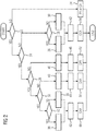
- FIG 1 illustrates a schematic diagram of a circuit for two cooking zones 18 and 20 of an induction cooking hob according to a preferred embodiment of the present invention.
- the circuit comprises a user interface 10, a micro controller 12, a first generator 14, a second generator 16, a first cooking zone 18 and a second cooking zone 20.
- the first cooking zone 18 corresponds with a first induction coil
- the second cooking zone 20 corresponds with a second induction coil.
- each cooking zone 18 and 20 may comprise one or more induction coils, wherein the induction coils of the same cooking zone 18 or 20 are supplied with the same frequency by a common generator 14 or 16, respectively.
- the induction coils of the first and second cooking zones 18 and 20 in FIG 1 are supplied with different frequencies by the first and second generators 14 and 16, respectively.
- the cooking zone 18 and/or 20 would comprise more induction coils, then the induction coils of the same cooking zone 18 or 20 are supplied with the same frequency by the common generator.
- the user interface 10 is operated by the user.
- the user selects a first requested power P1 for the first cooking zone 18 and/or a second requested power P2 for the second cooking zone 20 of said user interface 10.
- the micro controller 12 controls the first generator 14 and the second generator 16.
- the first generator 14 and the second generator 16 supply the cooking zones 18 and 20, respectively, with frequencies corresponding with the requested powers P1 and P2.
- the induction coils of the cooking zones 18 and 20 provide alternating magnetic fields for generating eddy currents in ferromagnetic portions of cooking utensils on the induction cooking hob in order to heat up said cooking utensils.
- the first generator 14 and the second generator 16 are never simultaneously activated in order to avoid acoustic noise. Either the first generator 14 or the second generator 16 is separately activated or both generators 14 and 16 are deactivated.
- the present invention provides four different algorithms for controlling the first generator 14 and the second generator 16, if the first requested power P1 and the second requested power P2 are both bigger than zero. The selection of one of said four algorithms depends on the amount and the relationship of the first requested power P1 for the first cooking zone 18 and the second requested power P2 for the second cooking zone 20. If one of the requested powers P1 and P2 is zero, then one of two conventional algorithms is activated.
- FIG 2 illustrates a schematic flow chart diagram for selecting the algorithm for controlling the both cooking zones 18 and 20 of the induction cooking hob according to the preferred embodiment of the present invention.
- the selection of the algorithm bases on six conditions 22, 24, 26 28, 30 and 32 for the first requested power P1 and the second requested power P2.
- the selection starts after the user has input the first requested power P1 and the second requested power P2 into the user interface 10.
- the first condition 22 is defined as P 1 > 0 AND P 2 > 0.
- the conventional algorithm 34 may be either a continuous mode or a pulsed mode. In the continuous mode the frequency of the generator 14 or 16 is regulated to meet the requested power P1 or P2, respectively, without any interruptions during the duty-cycle. In the pulsed mode the frequency of the generator 14 or 16 is regulated to meet a minimum deliverable power minDP, wherein the interruptions depend on the requested power P1 or P2.
- the second condition 24 is defined as P 1 ⁇ 50 % AND P 2 ⁇ 50 % in relation to the maximum deliverable power maxDP1 and maxDP2 of the first cooking zone 18 and second cooking zone 20, respectively.
- the third condition 26 is defined as P 1 + P 2 > 50 % , in relation to the respective maximum deliverable power maxDP1 and maxDP2 of the first cooking zone 18 and second cooking zone 20, while the fourth condition 28 is defined as P 1 > P 2.
- a step 36 the first cooking zone 18 is defined as a primary zone, while the second cooking zone 20 is defined a secondary zone. Otherwise, in a step 38 the second cooking zone 20 is defined as the primary zone, while the first cooking zone 18 is defined the secondary zone.
- a patterns adaptable period duty-cycle is evaluated in a step 42.
- a coupled continuous patterns algorithm is performed.
- the first cooking zone 18 and the second cooking zone 20 are defined as independent zones in a step 40.
- no primary or secondary zones are defined.
- a six-seconds-period duty-cycle is evaluated in a step 46.
- a coupled pulsed string algorithm (CPA) is performed.
- the fifth condition 30 is defined as P 1 ⁇ 25 % OR P 2 ⁇ 25 % in relation to the maximum deliverable power maxDP1 and maxDP2 of the first cooking zone 18 and second cooking zone 20, respectively.
- the first cooking zone 18 and the second cooking zone 20 are defined as independent zones in the step 40.
- no primary or secondary zones are defined.
- a patterns fixed period duty-cycle is evaluated in a step 44.
- a coupled half-time patterns algorithm (CHA) is performed.
- the sixth condition 32 is defined as P 1 ⁇ P 2.
- the first cooking zone 18 is defined as the secondary zone, while the second cooking zone 20 is defined as the primary zone, in the step 38.
- the first cooking zone 18 is defined as the primary zone, while the second cooking zone 20 is defined as the secondary zone, in the step 36.
- a patterns adaptable period duty-cycle is evaluated in the step 42.
- a coupled alternate patterns algorithm (CAA) is performed.
- FIG 3 illustrates a schematic time diagram of the coupled pulsed strings algorithm (CPA) for controlling the both cooking zones 18 and 20 of the induction cooking hob according to the preferred embodiment of the present invention.
- CPA coupled pulsed strings algorithm
- the coupled pulsed strings algorithm (CPA) is activated, if the requested powers P1 and P2 for the cooking zones 18 and 20, respectively, are bigger than zero and the sum of said requested powers P1 and P2 in relation to the respective maximum deliverable powers maxDP1 and maxDP2 of said cooking zones 18 and 20 are below 50%.
- the pulsed cycle period Tcp is six seconds.
- the table below shows the numerical values for the five cases of the coupled pulsed strings algorithm (CPA) shown in FIG 3 .
- first cooking zone second cooking zone both cooking zones
- FIG 4 illustrates a schematic time diagram of the coupled alternate patterns algorithm (CAA) for controlling the both cooking zones 18 and 20 of the induction cooking hob according to the preferred embodiment of the present invention.
- CAA coupled alternate patterns algorithm
- the coupled alternate patterns algorithm is activated, if the requested powers P1 and P2 of the cooking zones 18 and 20, respectively, are bigger than zero and the sum of said requested powers P1 and P2 in relation to the respective maximum deliverable powers maxDP1 and maxDP2 of said cooking zones 18 and 20 is between 50% and 100%, but the requested power P1 or P2 of one of the cooking zones 18 and 20 is below 25% of the related maximum deliverable power maxDP1 or maxDP2, respectively.
- the cooking zone 18 or 20 with the lower requested power P1 or P2, respectively, is selected as the primary zone, while the other one will be defined as the secondary zone.
- the first cooking zone 18 is the primary zone
- the second cooking zone 20 is the secondary zone.
- target power primary minDP 1
- target power secondary 100 * minDP 2 / Tpdc % secondary .
- the patterns are followed by time spread configurations, wherein the adaptable cycle period Tadcp of each cooking zone 18 and 20 changes according to the requested power P1 and P2 and the pattern duty-cycle activation time Tpdc. For example, a granularity of about 10% minimizes the power-off phase and preserves system from flickering noise.
- FIG 4 clarifies that never both cooking zones 18 and 20 area activated at the same time. Thus, no acoustic noise may occur.
- FIG 5 illustrates a schematic time diagram of the coupled half-time patterns algorithm (CHA) for controlling the both cooking zones 18 and 20 of the induction cooking hob according to the preferred embodiment of the present invention.
- CHA coupled half-time patterns algorithm
- the coupled half-time patterns algorithm (CHA) is activated, if the requested powers P1 and P2 of the cooking zones 18 and 20, respectively, are bigger than zero, the sum of said requested powers P1 and P2 in relation to the respective maximum deliverable power maxDP1 and maxDP2 is between 50% and 100%, but the requested powers P1 and P2 of any cooking zone 18 and 20 are not below 25% of the related maximum deliverable powers maxDP1 and maxDP2.
- the sum of duty-cycles will be always 100%, since both cooking zones 18 and 20 have the same cycle period.
- the frequency of each generator 14 and 16 is controlled, wherein the emitted power during the active phase doubles the minimum deliverable power minDP and the average level will meet the requested power P1 and P2.
- the patterns are followed a time spread configuration with a fixed cycle period Tfcp. For example, a granularity of about 10% minimizes the power-off phase and preserves system from flickering noise.
- FIG 5 clarifies that never both cooking zones 18 and 20 are activated at the same time, so that no acoustic noise may occur.
- FIG 6 illustrates a schematic time diagram of the coupled continuous patterns algorithm (CCA) for controlling the both cooking zones 18 and 20 of the induction cooking hob according to the preferred embodiment of the present invention.
- CCA coupled continuous patterns algorithm
- the coupled continuous patterns algorithm is activated, if the requested powers P1 and P2 of the cooking zones 18 and 20, respectively, are bigger than zero and at least one of said requested powers P1 and P2 is bigger than 50% of the maximum deliverable power maxDP1 and maxDP2, respectively.
- the cooking zone 18 or 20 with the higher requested power P1 or P2, respectively, is defined as the primary zone, while the other one is defined as the secondary zone.
- the second cooking zone 20 is defined as the primary zone.
- the generators 14 and 16 are controlled to work at similar frequencies defined to have a proper gap between each other.
- the second generator 16 for the primary zone is kept as reference.
- the value of the frequency difference is selected according to operative conditions and must be within a proper range in order to meet low acoustic beats interference on the one hand and minimized radiated and conducted emissions on the other hand.
- the target power corresponds with the requested power level P2.
- Each cooking zone 18 and 20 of the induction cooking hob has different characteristics. This results in a big influence on the power switch, i.e. IGBT, driving frequency. Additionally, each cooking vessel introduces a different parameter into the power control loop. At the moment of the frequency definition for the primary zone, the generator 14 for the secondary zone will be forced to operate using a driving period that depends on the primary zone. Constraints of this process are imposed by the system, e.g. the architecture of the generators 14 and 16, the induction coils, the characteristics of the cooking vessel and the driving method itself, in particular the frequency gap for the power distribution.
- FIG 7 illustrates a detailed time diagram of the coupled continuous patterns algorithm (CCA) for controlling the both cooking zones 18 and 20 of the induction cooking hob according to the preferred embodiment of the present invention.
- CCA coupled continuous patterns algorithm
- a first gate driving signal 56 and a second gate driving signal 58 for the power switches, i.e. IGBT, of the generators 14 and 16, respectively, are shown.
- the period of the primary zone is 40 ⁇ s, which corresponds with a driving frequency of 25.5kHz.
- the power-om period is 14 ⁇ s, while the power-off period is 26 ⁇ s.
- the time gap between the primary and secondary zones is about 2.5 ⁇ s.
- the period of the secondary zone is 37.5 ⁇ s, which corresponds with a driving frequency of 26.7kHz.
- the power-om period is 13 ⁇ s, while the power-off period is 24.5 ⁇ s.
- the activation time of the secondary zone depends on the PWM period of the primary zone related to power request P2. Further, the activation time depends on the coupling parameter of the induction coil and the cooking vessel. Moreover, the activation time depends on the frequency gap of the power distribution.
- the secondary pattern follows a time spread configuration, wherein the adaptable cycle period Tadcp changes according to the requested power and the target power of the secondary zone. For example, a granularity of 10% minimizes the power-off phase and preserves system from flickering noise.
Abstract
Description
- The present invention relates to a method for controlling a first cooking zone and a second cooking zone of an induction cooking hob.
- In an induction cooking hob acoustic noise may occur, if two or more cooking zones are working with slightly different frequencies at the same time. The acoustic noise is generated by interference between the slightly different frequencies.
-
WO 2016/010492 A1 discloses a method for reducing the audible noise in an induction cooking hob with a plurality of resonant inductors. The presence of cooking vessels is detected. A master resonant inductor is defined. A common switching frequency is determined for all resonant inductors. - It is an object of the present invention to provide a method for controlling two cooking zones of an induction cooking hob, which allows a reduced acoustic noise.
- The object is achieved by the method according to
claim 1. - According to the present invention a method for controlling a first cooking zone and a second cooking zone of an induction cooking hob is provided, wherein each cooking zone is supplied by a corresponding generator, and wherein the method comprises the steps of:
- inputting a requested power for each cooking zone,
- activating a one-zone mode, if the requested power for one cooking zone is bigger than zero and the requested power for the other one cooking zone is zero,
- activating a two-zones mode, if the requested powers for both cooking zones are bigger than zero, and
- if the two-zones mode is activated, then selecting an algorithm from a set of algorithms in dependence of the requested powers for the cooking zones.
- The core of the present invention is the selection of a suitable algorithm from the set of algorithms, if both cooking zones have to be activated. Said selection depends on the requested powers for the cooking zones. However, if only one cooking zone has to be activated, then a conventional method would be sufficient.
- Preferably, the selection of the algorithm depends on the values of the requested powers for the cooking zones.
- Further, the selection of the algorithm depends on the relationship of the requested powers for the cooking zones to each other.
- Moreover, the selection of the algorithm depends on the relationship between the requested powers for the cooking zones and the maximum deliverable powers and/or the minimum deliverable powers of said cooking zones.
- For example, in the one-zone mode a continuous mode is activated, wherein the frequency of the generator is regulated to meet the requested power without any interruptions during the duty-cycle.
- Alternatively, in the one-zone mode a pulsed mode is activated, wherein interruptions of said pulsed mode depend on the requested power for the cooking zone, and wherein preferably the frequency of the generator is regulated to meet a minimum deliverable power of said cooking zone.
- In the continuous mode the minimum and maximum deliverable powers are limited. For example, the minimum deliverable power may be several hundred watts. If the requested powers is lower than said minimum deliverable power, then the pulsed mode should be activated.
- According to one example, in the two-zones mode a coupled alternate patterns algorithm is activated, if the sum of the requested powers in relation to the respective maximum deliverable power of said cooking zones is between 50% and 100%, but the requested power of one of the cooking zones is below 25% of the of the related maximum deliverable power of said cooking zone.
- Preferably, the cooking zone with the lower requested power is defined as a primary zone, while the other one cooking zone is defined as a secondary zone, wherein a pattern duty-cycle activation time for the primary zone is defined as:


- According to another example, in the two-zones mode a coupled half-time patterns algorithm is activated, if the sum of the requested powers for the cooking zones in relation to the respective maximum deliverable powers of said cooking zones is between 50% and 100%, but the requested power of any cooking zone is not below 25% of the respective maximum deliverable power.
- In particular, the cooking zones are alternatingly activated for the same time period, so that one of the cooking zones is always activated.
- Preferably, during a power-on phase the emitted power of each cooking zone doubles the minimum deliverable power of said cooking zones, while the average power of each cooking zone corresponds with the request power for said of said cooking zones.
- According to a further example, in the two-zones mode a coupled pulsed strings algorithm is activated, if sum of the requested powers for the cooking zones in relation to the respective maximum deliverable powers of said cooking zones is below 50%.
- In particular, for each cooking zone a dedicated duty-cycle activation time related to a pulsed cycle period is calculated by


- According to an additional example, in the two-zones mode a coupled continuous patterns algorithm is activated, if at least one of the requested powers for the cooking zones is bigger than 50% of the maximum deliverable power of said cooking zone.
- Preferably, the cooking zone with the higher requested power is defined as a primary zone, while the other one cooking zone is defined as a secondary zone, wherein the primary zone runs in a continuous mode in order to meet the requested power, while the secondary zone uses the pattern duty-cycle activation time Tpdc related to an adaptable cycle period Tadcp:

- Novel and inventive features of the present invention are set forth in the appended claims.
- The present invention will be described in further detail with reference to the drawing, in which
- FIG 1
- illustrates a schematic diagram of a circuit for two cooking zones of an induction cooking hob according to a preferred embodiment of the present invention,
- FIG 2
- illustrates a schematic flow chart diagram for selecting an algorithm for controlling the both cooking zones of the induction cooking hob according to the preferred embodiment of the present invention,
- FIG 3
- illustrates a schematic time diagram of a coupled pulsed strings algorithm (CPA) for controlling the both cooking zones of the induction cooking hob according to the preferred embodiment of the present invention,
- FIG 4
- illustrates a schematic time diagram of a coupled alternate patterns algorithm (CAA) for controlling the both cooking zones of the induction cooking hob according to the preferred embodiment of the present invention,
- FIG 5
- illustrates a schematic time diagram of a coupled half-time patterns algorithm (CHA) for controlling the both cooking zones of the induction cooking hob according to the preferred embodiment of the present invention,
- FIG 6
- illustrates a schematic time diagram of a coupled continuous patterns algorithm (CCA) for controlling the both cooking zones of the induction cooking hob according to the preferred embodiment of the present invention, and
- FIG 7
- illustrates a detailed time diagram of the coupled continuous patterns algorithm (CCA) for controlling the both cooking zones of the induction cooking hob according to the preferred embodiment of the present invention.
-
FIG 1 illustrates a schematic diagram of a circuit for twocooking zones - The circuit comprises a
user interface 10, amicro controller 12, afirst generator 14, asecond generator 16, afirst cooking zone 18 and asecond cooking zone 20. In this example, thefirst cooking zone 18 corresponds with a first induction coil, while thesecond cooking zone 20 corresponds with a second induction coil. In general, eachcooking zone same cooking zone common generator second cooking zones FIG 1 are supplied with different frequencies by the first andsecond generators cooking zone 18 and/or 20 would comprise more induction coils, then the induction coils of thesame cooking zone - The
user interface 10 is operated by the user. In particular, the user selects a first requested power P1 for thefirst cooking zone 18 and/or a second requested power P2 for thesecond cooking zone 20 of saiduser interface 10. - The
micro controller 12 controls thefirst generator 14 and thesecond generator 16. Thefirst generator 14 and thesecond generator 16 supply thecooking zones - The induction coils of the
cooking zones - The
first generator 14 and thesecond generator 16 are never simultaneously activated in order to avoid acoustic noise. Either thefirst generator 14 or thesecond generator 16 is separately activated or bothgenerators first generator 14 and thesecond generator 16, if the first requested power P1 and the second requested power P2 are both bigger than zero. The selection of one of said four algorithms depends on the amount and the relationship of the first requested power P1 for thefirst cooking zone 18 and the second requested power P2 for thesecond cooking zone 20. If one of the requested powers P1 and P2 is zero, then one of two conventional algorithms is activated. -
FIG 2 illustrates a schematic flow chart diagram for selecting the algorithm for controlling the bothcooking zones - In this example, the selection of the algorithm bases on six
conditions user interface 10. Thefirst condition 22 is defined as
- If the
first condition 22 is fulfilled, then bothcooking zones cooking zones conventional algorithm 34. In theconventional algorithm 34 only one of thegenerators conventional algorithm 34 may be either a continuous mode or a pulsed mode. In the continuous mode the frequency of thegenerator generator - If the
first condition 22 is fulfilled, then thesecond condition 24 has to be checked. Thesecond condition 24 is defined as
first cooking zone 18 andsecond cooking zone 20, respectively. - If the
second condition 24 is fulfilled, then thethird condition 26 has to be checked. Otherwise, thefourth condition 28 has to be checked. Thethird condition 26 is defined as
first cooking zone 18 andsecond cooking zone 20, while thefourth condition 28 is defined as
- If the
fourth condition 28 is fulfilled, then in astep 36 thefirst cooking zone 18 is defined as a primary zone, while thesecond cooking zone 20 is defined a secondary zone. Otherwise, in astep 38 thesecond cooking zone 20 is defined as the primary zone, while thefirst cooking zone 18 is defined the secondary zone. Then, after thestep step 42. Then, in a step 54 a coupled continuous patterns algorithm (CCA) is performed. - If the
third condition 26 is not fulfilled, then thefirst cooking zone 18 and thesecond cooking zone 20 are defined as independent zones in astep 40. In thestep 40, no primary or secondary zones are defined. Then, a six-seconds-period duty-cycle is evaluated in astep 46. Then, in a step 52 a coupled pulsed string algorithm (CPA) is performed. - If the
third condition 26 is fulfilled, then thefifth condition 30 has to be checked. Thefifth condition 30 is defined as
first cooking zone 18 andsecond cooking zone 20, respectively. - If the
fifth condition 30 is not fulfilled, then thefirst cooking zone 18 and thesecond cooking zone 20 are defined as independent zones in thestep 40. In saidstep 40, no primary or secondary zones are defined. Then, a patterns fixed period duty-cycle is evaluated in astep 44. Then, in a step 50 a coupled half-time patterns algorithm (CHA) is performed. - If the
fifth condition 30 is fulfilled, then asixth condition 32 has to be checked. Thesixth condition 32 is defined as
- If the
sixth condition 32 is not fulfilled, then thefirst cooking zone 18 is defined as the secondary zone, while thesecond cooking zone 20 is defined as the primary zone, in thestep 38. In contrast, if thesixth condition 32 is fulfilled, then thefirst cooking zone 18 is defined as the primary zone, while thesecond cooking zone 20 is defined as the secondary zone, in thestep 36. - Then, after the
step step 42. Then, in a step 48 a coupled alternate patterns algorithm (CAA) is performed. -
FIG 3 illustrates a schematic time diagram of the coupled pulsed strings algorithm (CPA) for controlling the bothcooking zones - The coupled pulsed strings algorithm (CPA) is activated, if the requested powers P1 and P2 for the
cooking zones cooking zones cooking zone 18 and 20 a dedicated duty-cycle activation time Tdc related to a pulsed cycle period Tcp is calculated by

cooking zone 
- Since the sum of the requested powers P1 and P2 is below 50% of the maximum deliverable power maxDP, the total duty-cycle activation time Tdc is always below 100%.
- The table below shows the numerical values for the five cases of the coupled pulsed strings algorithm (CPA) shown in
FIG 3 .first cooking zone second cooking zone both cooking zones Case maxDP1 = 1400W maxDP2 = 2000W maxDP = 3400W minDP1 = 700W minDP2 = 1000W minDP = 1700W P1: Tdc%: P2: Tdc%: P1+P2: Tdc%: 1 490W (35%) 70% 300W (15%) 30% 790W (50%) 100% 2 210W (15%) 30% 700W (35%) 70% 910W (50%) 100% 3 140W (10%) 20% 500W (25%) 50% 640W (35%) 70% 4 350W (25%) 50% 200W (10%) 20% 550W (35%) 70% 5 140W (10%) 20% 200W (10%) 20% 340W (20%) 40% - Always, at the most one of the both
cooking zones -
FIG 4 illustrates a schematic time diagram of the coupled alternate patterns algorithm (CAA) for controlling the bothcooking zones - The coupled alternate patterns algorithm (CAA) is activated, if the requested powers P1 and P2 of the
cooking zones cooking zones cooking zones - The
cooking zone first cooking zone 18 is the primary zone, while thesecond cooking zone 20 is the secondary zone. - The primary zone imposes a pattern duty-cycle activation time Tpdc related to an adaptable cycle period Tadcp:


- The sum of the duty-cycles must be always 100% of the selected cycle period in order to meet that the primary zone generates a power equal to the minimum deliverable power minDP during the active phase:


- The patterns are followed by time spread configurations, wherein the adaptable cycle period Tadcp of each
cooking zone - The table below shows the numerical values for the five cases of the coupled alternate patterns algorithm (CAA) shown in
FIG 4 .Case first cooking zone second cooking zone both cooking zones maxDP1 = 1400W maxDP2 = 2000W maxDP = 3400W minDP1 = 700W minDP2 = 1000W minDP = 1700W P1: Tpdc%: P2: Tpdc%: P1+P2: Tpdc%: 1 70W (5%) 10% 1000W (50%) 90% 1070W (55%) 100% 2 560W (40%) 80% 200W (10%) 20% 960W (60%) 100% 3 350W (15%) 30% 800W (40%) 70% 1150W (65%) 100% 4 630W (45%) 60% 400W (20%) 40% 1130W (70%) 100% 5 700W (50%) 50% 500W (25%) 50% 1130W (75%) 100% -
FIG 4 clarifies that never bothcooking zones -
FIG 5 illustrates a schematic time diagram of the coupled half-time patterns algorithm (CHA) for controlling the bothcooking zones - The coupled half-time patterns algorithm (CHA) is activated, if the requested powers P1 and P2 of the
cooking zones cooking zone - In the coupled half-time patterns algorithm (CHA) the selection of primary and secondary zone is not required, since both
cooking zones 

- The sum of duty-cycles will be always 100%, since both
cooking zones generator - The table below shows the numerical values for the five cases of the coupled half-time patterns algorithm (CHA) shown in
FIG 5 .first cooking zone second cooking zone both cooking zones Case maxDP1 = 1400W maxDP2 = 2000W maxDP = 3400W minDP1 = 700W minDP2 = 1000W minDP = 1700W P1: Tdc%: P2: Tdc%: P1+P2: Tdc%: 1 350W (25%) 50% 600W (30%) 50% 1070W (55%) 100% 2 420W (30%) 50% 700W (35%) 50% 960W (65%) 100% 3 490W (35%) 50% 800W (40%) 50% 1150W (75%) 100% 4 560W (40%) 50% 900W (45%) 50% 1130W (85%) 100% 5 630W (45%) 50% 1000W (50%) 50% 1130W (95%) 100% -
FIG 5 clarifies that never bothcooking zones -
FIG 6 illustrates a schematic time diagram of the coupled continuous patterns algorithm (CCA) for controlling the bothcooking zones - The coupled continuous patterns algorithm (CCA) is activated, if the requested powers P1 and P2 of the
cooking zones - The
cooking zone second cooking zone 20 is defined as the primary zone. - The
generators second generator 16 for the primary zone is kept as reference. The value of the frequency difference is selected according to operative conditions and must be within a proper range in order to meet low acoustic beats interference on the one hand and minimized radiated and conducted emissions on the other hand. - The reference switching frequency is imposed by the primary zone, wherein said primary zone runs in a continuous mode in order to meet the requested power level P2:

- In standard conditions, the target power corresponds with the requested power level P2.
- The
first cooking zone 18, i.e. the secondary zone, uses the pattern duty-cycle activation time Tpdc related to an adaptable cycle period Tadcp, which depends on its target power and is imposed by the primary zone:

- The table below shows the numerical values for the eight cases of the coupled continuous patterns algorithm (CCA) shown in
FIG 6 .first cooking zone second cooking zones maxDP1 = 1400W maxDP2 = 3400W Case minDP1 = 700W minDP2 = 1700W target power: P1: Tdc%: P2: frequency: 1 700W (50%) 140W (10%) 20% 1200W (60%) 28kHz 2 560W (40%) 210W (10%) 30% 1200W (60%) 28kHz 3 350W (15%) 400W (40%) 40% 1500W (75%) 26kHz 4 630W (45%) 500W (20%) 50% 1500W (75%) 26kHz 5 700W (50%) 700W (25%) 60% 1750W (87%) 24kHz 6 350W (15%) 800W (40%) 70% 1750W (87%) 24kHz 7 1300W (45%) 1050W (20%) 80% 2000W (100%) 22kHz 8 1300W (50%) 1200W (25%) 90% 2000W (100%) 22kHz - Each
cooking zone generator 14 for the secondary zone will be forced to operate using a driving period that depends on the primary zone. Constraints of this process are imposed by the system, e.g. the architecture of thegenerators -
FIG 7 illustrates a detailed time diagram of the coupled continuous patterns algorithm (CCA) for controlling the bothcooking zones - A first
gate driving signal 56 and a secondgate driving signal 58 for the power switches, i.e. IGBT, of thegenerators - The period of the primary zone is 40µs, which corresponds with a driving frequency of 25.5kHz. The power-om period is 14µs, while the power-off period is 26 µs. The time gap between the primary and secondary zones is about 2.5µs. Thus, the period of the secondary zone is 37.5µs, which corresponds with a driving frequency of 26.7kHz. The power-om period is 13µs, while the power-off period is 24.5µs.
- The activation time of the secondary zone depends on the PWM period of the primary zone related to power request P2. Further, the activation time depends on the coupling parameter of the induction coil and the cooking vessel. Moreover, the activation time depends on the frequency gap of the power distribution.
- In order to achieve requested power, only the driving frequency of the primary zone will be directly adjusted within a specified range, while the selection of the pattern and the regulation of the time gap act on the power for the secondary zone. The secondary pattern follows a time spread configuration, wherein the adaptable cycle period Tadcp changes according to the requested power and the target power of the secondary zone. For example, a granularity of 10% minimizes the power-off phase and preserves system from flickering noise.
- Although an illustrative embodiment of the present invention has been described herein with reference to the accompanying drawings, it is to be understood that the present invention is not limited to that precise embodiment, and that various other changes and modifications may be affected therein by one skilled in the art without departing from the scope or spirit of the invention. All such changes and modifications are intended to be included within the scope of the invention as defined by the appended claims.
-
- 10
- user interface
- 12
- micro controller
- 14
- first generator
- 16
- second generator
- 18
- first cooking zone
- 20
- second cooking zone
- 22
- first condition
- 24
- second condition
- 26
- third condition
- 28
- fourth condition
- 30
- fifth condition
- 32
- sixth condition
- 34
- step of performing the conventional algorithm
- 36
- step of defining the first cooking zone as primary zone and the second cooking zone as secondary zone
- 38
- step of defining the first cooking zone as secondary zone and the second cooking zone as primary zone
- 40
- step of defining both cooking zones as independent zones
- 42
- step of evaluating patterns adaptable period duty-cycle
- 44
- step of evaluating patterns forced period duty-cycle
- 46
- step of evaluating six-seconds period duty-cycle
- 48
- step of performing the coupled alternate patterns algorithm
- 50
- step of performing the coupled half-time patterns algorithm
- 52
- step of performing the coupled pulsed strings algorithm
- 54
- step of performing the coupled continuous patterns algorithm
- 56
- first gate driving signal
- 58
- second gate driving signal
- P1
- requested power of the first cooking zone
- P2
- requested power of the second cooking zone
- maxDP1
- maximum deliverable power of the first cooking zone
- maxDP2
- maximum deliverable power of the second cooking zone
- maxDP
- total maximum deliverable power
- minDP1
- minimum deliverable power of the first cooking zone
- minDP2
- minimum deliverable power of the second cooking zone
- minDP
- total minimum deliverable power
- Tdc
- duty-cycle activation time
- Tdc1
- duty-cycle activation time of the first cooking zone
- Tdc2
- duty-cycle activation time of the second cooking zone
- Tdc%
- percentage duty-cycle activation time
- Tcp
- pulsed cycle period
- Tpdc
- pattern duty-cycle activation time
- Tadcp
- adaptable cycle period
Claims (15)
- A method for controlling a first cooking zone (18) and a second cooking zone (20) of an induction cooking hob, wherein each cooking zone (18, 20) is supplied by a corresponding generator (14, 16), and wherein the method comprises the steps of:- inputting a requested power (P1, P2) for each cooking zone (18, 20),- activating a one-zone mode, if the requested power (P1, P2) for one cooking zone (18, 20) is bigger than zero and the requested power (P2, P1) for the other one cooking zone (18, 20) is zero,- activating a two-zones mode, if the requested powers (P1, P2) for both cooking zones (18, 20) are bigger than zero, and- if the two-zones mode is activated, then selecting an algorithm (48, 50, 52, 54) from a set of algorithms (48, 50, 52, 54) in dependence of the requested powers (P1, P2) for the cooking zones (18, 20).
- The method according to claim 1,
characterised in that
the selection of the algorithm (48, 50, 52, 54) depends on the values of the requested powers (P1, P2) for the cooking zones (18, 20). - The method according to claim 1 or 2,
characterised in that
the selection of the algorithm (48, 50, 52, 54) depends on the relationship of the requested powers (P1, P2) for the cooking zones (18, 20) to each other. - The method according to any one of the preceding claims,
characterised in that
the selection of the algorithm (48, 50, 52, 54) depends on the relationship between the requested powers (P1, P2) for the cooking zones (18, 20) and the maximum deliverable powers (maxDP1, maxDP2) and/or the minimum deliverable powers (minDP1, minDP2) of said cooking zones (18, 20). - The method according to any one of the preceding claims,
characterised in that
in the one-zone mode a continuous mode is activated, wherein the frequency of the generator (14, 16) is regulated to meet the requested power P1 or P2, respectively, without any interruptions during the duty-cycle. - The method according to any one of the claims 1 to 4,
characterised in that
in the one-zone mode a pulsed mode is activated, wherein interruptions of said pulsed mode depend on the requested power (P1, P2) for the cooking zone (18, 20), and wherein preferably the frequency of the generator (14, 16) is regulated to meet a minimum deliverable power (minDP1, minDP2) of said cooking zone (18, 20). - The method according to any one of the preceding claims,
characterised in that
in the two-zones mode a coupled alternate patterns algorithm (48) is activated, if the sum of the requested powers (P1, P2) in relation to the respective maximum deliverable power (maxDP1, maxDP2) of said cooking zones (18, 20) is between 50% and 100%, but the requested power (P1, P2) of one of the cooking zones (18, 20) is below 25% of the of the related maximum deliverable power (maxDP1, maxDP2) of said cooking zone (18, 20). - The method according to claim 7,
characterised in that
the cooking zone (18, 20) with the lower requested power (P1, P2) is defined as a primary zone, while the other one cooking zone (18, 20) is defined as a secondary zone, wherein a pattern duty-cycle activation time (Tpdc) for the primary zone is defined as:

while the remaining time is provided for the pattern duty-cycle activation time (Tpdc) for the secondary zone, wherein Tadcp is an adaptable cycle period and minDP1 and minDP2 are the maximum deliverable power of the first and second cooking zone (18, 20), respectively. - The method according to any one of the preceding claims,
characterised in that
in the two-zones mode a coupled half-time patterns algorithm (50) is activated, if the sum of the requested powers (P1, P2) for the cooking zones (18, 20) in relation to the respective maximum deliverable power (maxDP1, maxDP2) of said cooking zones (18, 20) is between 50% and 100%, but the requested power (P1, P2) of any cooking zone (18, 20) is not below 25% of the respective maximum deliverable power (maxDP1, maxDP2). - The method according to claim 9,
characterised in that
the cooking zones (18, 20) are alternatingly activated for the same time period, so that one of the cooking zones (18, 20) is always activated. - The method according to claim 9 or 10,
characterised in that
during a power-on phase the emitted power of each cooking zone (18, 20) doubles the minimum deliverable powers (minDP1, minDP2) of said cooking zones (18, 20), while the average power of each cooking zone (18, 20) corresponds with the request power (P1, P2) for said of said cooking zones (18, 20). - The method according to any one of the preceding claims,
characterised in that
in the two-zones mode a coupled pulsed strings algorithm (52) is activated, if the sum of the requested powers (P1, P2) for the cooking zones (18, 20) in relation to the respective maximum deliverable power (maxDP1, maxDP2) of said cooking zones (18, 20) is below 50%. - The method according to claim 9,
characterised in that
for each cooking zone (18, 20) a dedicated duty-cycle activation time (Tdc1, Tdcl2) related to a pulsed cycle period (Tcp) is calculated by

- The method according to any one of the preceding claims,
characterised in that
in the two-zones mode a coupled continuous patterns algorithm (54) is activated, if at least one the requested powers (P1, P2) for the cooking zones (18, 20) is bigger than 50% of the maximum deliverable power (maxDP1, maxDP2) of said cooking zone (18, 20). - The method according to claim 14,
characterised in that
the cooking zone (18, 20) with the higher requested power (P1, P2) is defined as a primary zone, while the other one cooking zone (18, 20) is defined as a secondary zone, wherein the primary zone runs in a continuous mode in order to meet the requested power (P1, p2), while the secondary zone uses the pattern duty-cycle activation time (Tpdc) related to an adaptable cycle period (Tadcp):
Priority Applications (6)
| Application Number | Priority Date | Filing Date | Title |
|---|---|---|---|
| EP18178151.9A EP3582587B1 (en) | 2018-06-16 | 2018-06-16 | Method for controlling two cooking zones of an induction cooking hob |
| PCT/EP2019/064308 WO2019238448A1 (en) | 2018-06-16 | 2019-06-03 | Method for controlling two cooking zones of an induction cooking hob |
| CN201980037090.2A CN112219448B (en) | 2018-06-16 | 2019-06-03 | Method for controlling two cooking zones of an induction cooking hob |
| BR112020025544-0A BR112020025544A2 (en) | 2018-06-16 | 2019-06-03 | METHOD TO CONTROL TWO COOKING ZONES OF AN INDUCTION COOKING PLATE |
| US17/059,964 US20210212174A1 (en) | 2018-06-16 | 2019-06-03 | Method for controlling two cooking zones of an induction cooking hob |
| AU2019284796A AU2019284796B2 (en) | 2018-06-16 | 2019-06-03 | Method for controlling two cooking zones of an induction cooking hob |
Applications Claiming Priority (1)
| Application Number | Priority Date | Filing Date | Title |
|---|---|---|---|
| EP18178151.9A EP3582587B1 (en) | 2018-06-16 | 2018-06-16 | Method for controlling two cooking zones of an induction cooking hob |
Publications (2)
| Publication Number | Publication Date |
|---|---|
| EP3582587A1 true EP3582587A1 (en) | 2019-12-18 |
| EP3582587B1 EP3582587B1 (en) | 2022-09-28 |
Family
ID=62705450
Family Applications (1)
| Application Number | Title | Priority Date | Filing Date |
|---|---|---|---|
| EP18178151.9A Active EP3582587B1 (en) | 2018-06-16 | 2018-06-16 | Method for controlling two cooking zones of an induction cooking hob |
Country Status (6)
| Country | Link |
|---|---|
| US (1) | US20210212174A1 (en) |
| EP (1) | EP3582587B1 (en) |
| CN (1) | CN112219448B (en) |
| AU (1) | AU2019284796B2 (en) |
| BR (1) | BR112020025544A2 (en) |
| WO (1) | WO2019238448A1 (en) |
Families Citing this family (1)
| Publication number | Priority date | Publication date | Assignee | Title |
|---|---|---|---|---|
| EP4195875A1 (en) * | 2021-12-10 | 2023-06-14 | SABAF S.p.A. | Induction cooktop and method for controlling an induction cooktop |
Citations (4)
| Publication number | Priority date | Publication date | Assignee | Title |
|---|---|---|---|---|
| EP0844807A1 (en) * | 1996-11-21 | 1998-05-27 | Balay S.A. | Optimal Control of the installed power in domestic induction cooking hobs with re-configurable structure topology |
| US20110163086A1 (en) * | 2008-09-30 | 2011-07-07 | BSH Bosch und Siemens Hausgeräte GmbH | Cooktop and method for operating a cooktop |
| US20140151365A1 (en) * | 2012-12-03 | 2014-06-05 | Dooyong OH | Electronic induction heating cooker and output level control method thereof |
| WO2016010492A1 (en) | 2014-07-15 | 2016-01-21 | Arçeli̇k Anoni̇m Şi̇rketi̇ | System and method for improving noise performance of multi-zone quasi-resonant inverter induction heater |
Family Cites Families (1)
| Publication number | Priority date | Publication date | Assignee | Title |
|---|---|---|---|---|
| ES2645734T3 (en) * | 2011-03-30 | 2017-12-07 | BSH Hausgeräte GmbH | Induction heating device |
-
2018
- 2018-06-16 EP EP18178151.9A patent/EP3582587B1/en active Active
-
2019
- 2019-06-03 WO PCT/EP2019/064308 patent/WO2019238448A1/en active Application Filing
- 2019-06-03 US US17/059,964 patent/US20210212174A1/en active Pending
- 2019-06-03 AU AU2019284796A patent/AU2019284796B2/en active Active
- 2019-06-03 BR BR112020025544-0A patent/BR112020025544A2/en unknown
- 2019-06-03 CN CN201980037090.2A patent/CN112219448B/en active Active
Patent Citations (4)
| Publication number | Priority date | Publication date | Assignee | Title |
|---|---|---|---|---|
| EP0844807A1 (en) * | 1996-11-21 | 1998-05-27 | Balay S.A. | Optimal Control of the installed power in domestic induction cooking hobs with re-configurable structure topology |
| US20110163086A1 (en) * | 2008-09-30 | 2011-07-07 | BSH Bosch und Siemens Hausgeräte GmbH | Cooktop and method for operating a cooktop |
| US20140151365A1 (en) * | 2012-12-03 | 2014-06-05 | Dooyong OH | Electronic induction heating cooker and output level control method thereof |
| WO2016010492A1 (en) | 2014-07-15 | 2016-01-21 | Arçeli̇k Anoni̇m Şi̇rketi̇ | System and method for improving noise performance of multi-zone quasi-resonant inverter induction heater |
Also Published As
| Publication number | Publication date |
|---|---|
| EP3582587B1 (en) | 2022-09-28 |
| US20210212174A1 (en) | 2021-07-08 |
| BR112020025544A2 (en) | 2021-03-16 |
| AU2019284796B2 (en) | 2023-07-06 |
| WO2019238448A1 (en) | 2019-12-19 |
| CN112219448B (en) | 2023-09-22 |
| AU2019284796A1 (en) | 2020-12-10 |
| CN112219448A (en) | 2021-01-12 |
Similar Documents
| Publication | Publication Date | Title |
|---|---|---|
| US11700675B2 (en) | Induction cooking hob including a cooking area with three or more induction coils and a method for controlling a cooking area | |
| EP3771288B1 (en) | Method for supplying power to induction cooking zones of an induction cooking hob having a plurality of power converters, and induction cooking hob using such method | |
| US11064573B2 (en) | Determining resonant frequency for quasi-resonant induction cooking devices | |
| EP2836053B1 (en) | Induction hob and method for operating an induction hob | |
| EP3582587B1 (en) | Method for controlling two cooking zones of an induction cooking hob | |
| EP3709769B1 (en) | Induction-heating cooker | |
| KR20180002247A (en) | Electric range and control method for the electric range | |
| KR101857662B1 (en) | Electric range controlling multiple working coil with frequency and duty | |
| US6472649B2 (en) | Microwave oven and method of controlling the same | |
| US20230009984A1 (en) | Induction device | |
| JP4325446B2 (en) | Induction heating device | |
| US20220191976A1 (en) | Cooking appliance | |
| KR101846358B1 (en) | Electric range having multiple inverter circuits driven by same frequency and control method for the electric range | |
| JP2003123955A (en) | Induction heating cooker | |
| JP2642823B2 (en) | Electromagnetic cooker | |
| JPH03114194A (en) | Induction heating cooking apparatus | |
| JP2006179271A (en) | Compound heating cooking device | |
| JP2002134257A (en) | Cooker power supply equipment | |
| JP2005000348A (en) | Electric rice-cooker |
Legal Events
| Date | Code | Title | Description |
|---|---|---|---|
| PUAI | Public reference made under article 153(3) epc to a published international application that has entered the european phase |
Free format text: ORIGINAL CODE: 0009012 |
|
| STAA | Information on the status of an ep patent application or granted ep patent |
Free format text: STATUS: THE APPLICATION HAS BEEN PUBLISHED |
|
| AK | Designated contracting states |
Kind code of ref document: A1 Designated state(s): AL AT BE BG CH CY CZ DE DK EE ES FI FR GB GR HR HU IE IS IT LI LT LU LV MC MK MT NL NO PL PT RO RS SE SI SK SM TR |
|
| AX | Request for extension of the european patent |
Extension state: BA ME |
|
| STAA | Information on the status of an ep patent application or granted ep patent |
Free format text: STATUS: REQUEST FOR EXAMINATION WAS MADE |
|
| STAA | Information on the status of an ep patent application or granted ep patent |
Free format text: STATUS: EXAMINATION IS IN PROGRESS |
|
| 17P | Request for examination filed |
Effective date: 20200618 |
|
| RBV | Designated contracting states (corrected) |
Designated state(s): AL AT BE BG CH CY CZ DE DK EE ES FI FR GB GR HR HU IE IS IT LI LT LU LV MC MK MT NL NO PL PT RO RS SE SI SK SM TR |
|
| 17Q | First examination report despatched |
Effective date: 20200717 |
|
| STAA | Information on the status of an ep patent application or granted ep patent |
Free format text: STATUS: EXAMINATION IS IN PROGRESS |
|
| STAA | Information on the status of an ep patent application or granted ep patent |
Free format text: STATUS: EXAMINATION IS IN PROGRESS |
|
| GRAP | Despatch of communication of intention to grant a patent |
Free format text: ORIGINAL CODE: EPIDOSNIGR1 |
|
| STAA | Information on the status of an ep patent application or granted ep patent |
Free format text: STATUS: GRANT OF PATENT IS INTENDED |
|
| INTG | Intention to grant announced |
Effective date: 20220502 |
|
| GRAS | Grant fee paid |
Free format text: ORIGINAL CODE: EPIDOSNIGR3 |
|
| GRAA | (expected) grant |
Free format text: ORIGINAL CODE: 0009210 |
|
| STAA | Information on the status of an ep patent application or granted ep patent |
Free format text: STATUS: THE PATENT HAS BEEN GRANTED |
|
| AK | Designated contracting states |
Kind code of ref document: B1 Designated state(s): AL AT BE BG CH CY CZ DE DK EE ES FI FR GB GR HR HU IE IS IT LI LT LU LV MC MK MT NL NO PL PT RO RS SE SI SK SM TR |
|
| REG | Reference to a national code |
Ref country code: GB Ref legal event code: FG4D |
|
| REG | Reference to a national code |
Ref country code: CH Ref legal event code: EP |
|
| REG | Reference to a national code |
Ref country code: DE Ref legal event code: R096 Ref document number: 602018041048 Country of ref document: DE |
|
| REG | Reference to a national code |
Ref country code: AT Ref legal event code: REF Ref document number: 1522151 Country of ref document: AT Kind code of ref document: T Effective date: 20221015 |
|
| REG | Reference to a national code |
Ref country code: IE Ref legal event code: FG4D |
|
| REG | Reference to a national code |
Ref country code: LT Ref legal event code: MG9D |
|
| PG25 | Lapsed in a contracting state [announced via postgrant information from national office to epo] |
Ref country code: SE Free format text: LAPSE BECAUSE OF FAILURE TO SUBMIT A TRANSLATION OF THE DESCRIPTION OR TO PAY THE FEE WITHIN THE PRESCRIBED TIME-LIMIT Effective date: 20220928 Ref country code: RS Free format text: LAPSE BECAUSE OF FAILURE TO SUBMIT A TRANSLATION OF THE DESCRIPTION OR TO PAY THE FEE WITHIN THE PRESCRIBED TIME-LIMIT Effective date: 20220928 Ref country code: NO Free format text: LAPSE BECAUSE OF FAILURE TO SUBMIT A TRANSLATION OF THE DESCRIPTION OR TO PAY THE FEE WITHIN THE PRESCRIBED TIME-LIMIT Effective date: 20221228 Ref country code: LV Free format text: LAPSE BECAUSE OF FAILURE TO SUBMIT A TRANSLATION OF THE DESCRIPTION OR TO PAY THE FEE WITHIN THE PRESCRIBED TIME-LIMIT Effective date: 20220928 Ref country code: LT Free format text: LAPSE BECAUSE OF FAILURE TO SUBMIT A TRANSLATION OF THE DESCRIPTION OR TO PAY THE FEE WITHIN THE PRESCRIBED TIME-LIMIT Effective date: 20220928 Ref country code: FI Free format text: LAPSE BECAUSE OF FAILURE TO SUBMIT A TRANSLATION OF THE DESCRIPTION OR TO PAY THE FEE WITHIN THE PRESCRIBED TIME-LIMIT Effective date: 20220928 |
|
| REG | Reference to a national code |
Ref country code: NL Ref legal event code: MP Effective date: 20220928 |
|
| REG | Reference to a national code |
Ref country code: AT Ref legal event code: MK05 Ref document number: 1522151 Country of ref document: AT Kind code of ref document: T Effective date: 20220928 |
|
| PG25 | Lapsed in a contracting state [announced via postgrant information from national office to epo] |
Ref country code: HR Free format text: LAPSE BECAUSE OF FAILURE TO SUBMIT A TRANSLATION OF THE DESCRIPTION OR TO PAY THE FEE WITHIN THE PRESCRIBED TIME-LIMIT Effective date: 20220928 Ref country code: GR Free format text: LAPSE BECAUSE OF FAILURE TO SUBMIT A TRANSLATION OF THE DESCRIPTION OR TO PAY THE FEE WITHIN THE PRESCRIBED TIME-LIMIT Effective date: 20221229 |
|
| PG25 | Lapsed in a contracting state [announced via postgrant information from national office to epo] |
Ref country code: SM Free format text: LAPSE BECAUSE OF FAILURE TO SUBMIT A TRANSLATION OF THE DESCRIPTION OR TO PAY THE FEE WITHIN THE PRESCRIBED TIME-LIMIT Effective date: 20220928 Ref country code: RO Free format text: LAPSE BECAUSE OF FAILURE TO SUBMIT A TRANSLATION OF THE DESCRIPTION OR TO PAY THE FEE WITHIN THE PRESCRIBED TIME-LIMIT Effective date: 20220928 Ref country code: PT Free format text: LAPSE BECAUSE OF FAILURE TO SUBMIT A TRANSLATION OF THE DESCRIPTION OR TO PAY THE FEE WITHIN THE PRESCRIBED TIME-LIMIT Effective date: 20230130 Ref country code: ES Free format text: LAPSE BECAUSE OF FAILURE TO SUBMIT A TRANSLATION OF THE DESCRIPTION OR TO PAY THE FEE WITHIN THE PRESCRIBED TIME-LIMIT Effective date: 20220928 Ref country code: CZ Free format text: LAPSE BECAUSE OF FAILURE TO SUBMIT A TRANSLATION OF THE DESCRIPTION OR TO PAY THE FEE WITHIN THE PRESCRIBED TIME-LIMIT Effective date: 20220928 Ref country code: AT Free format text: LAPSE BECAUSE OF FAILURE TO SUBMIT A TRANSLATION OF THE DESCRIPTION OR TO PAY THE FEE WITHIN THE PRESCRIBED TIME-LIMIT Effective date: 20220928 |
|
| PG25 | Lapsed in a contracting state [announced via postgrant information from national office to epo] |
Ref country code: SK Free format text: LAPSE BECAUSE OF FAILURE TO SUBMIT A TRANSLATION OF THE DESCRIPTION OR TO PAY THE FEE WITHIN THE PRESCRIBED TIME-LIMIT Effective date: 20220928 Ref country code: PL Free format text: LAPSE BECAUSE OF FAILURE TO SUBMIT A TRANSLATION OF THE DESCRIPTION OR TO PAY THE FEE WITHIN THE PRESCRIBED TIME-LIMIT Effective date: 20220928 Ref country code: IS Free format text: LAPSE BECAUSE OF FAILURE TO SUBMIT A TRANSLATION OF THE DESCRIPTION OR TO PAY THE FEE WITHIN THE PRESCRIBED TIME-LIMIT Effective date: 20230128 Ref country code: EE Free format text: LAPSE BECAUSE OF FAILURE TO SUBMIT A TRANSLATION OF THE DESCRIPTION OR TO PAY THE FEE WITHIN THE PRESCRIBED TIME-LIMIT Effective date: 20220928 |
|
| REG | Reference to a national code |
Ref country code: DE Ref legal event code: R097 Ref document number: 602018041048 Country of ref document: DE |
|
| PG25 | Lapsed in a contracting state [announced via postgrant information from national office to epo] |
Ref country code: NL Free format text: LAPSE BECAUSE OF FAILURE TO SUBMIT A TRANSLATION OF THE DESCRIPTION OR TO PAY THE FEE WITHIN THE PRESCRIBED TIME-LIMIT Effective date: 20220928 Ref country code: AL Free format text: LAPSE BECAUSE OF FAILURE TO SUBMIT A TRANSLATION OF THE DESCRIPTION OR TO PAY THE FEE WITHIN THE PRESCRIBED TIME-LIMIT Effective date: 20220928 |
|
| PG25 | Lapsed in a contracting state [announced via postgrant information from national office to epo] |
Ref country code: DK Free format text: LAPSE BECAUSE OF FAILURE TO SUBMIT A TRANSLATION OF THE DESCRIPTION OR TO PAY THE FEE WITHIN THE PRESCRIBED TIME-LIMIT Effective date: 20220928 |
|
| PGFP | Annual fee paid to national office [announced via postgrant information from national office to epo] |
Ref country code: FR Payment date: 20230622 Year of fee payment: 6 Ref country code: DE Payment date: 20230627 Year of fee payment: 6 |
|
| P01 | Opt-out of the competence of the unified patent court (upc) registered |
Effective date: 20230625 |
|
| PLBE | No opposition filed within time limit |
Free format text: ORIGINAL CODE: 0009261 |
|
| STAA | Information on the status of an ep patent application or granted ep patent |
Free format text: STATUS: NO OPPOSITION FILED WITHIN TIME LIMIT |
|
| 26N | No opposition filed |
Effective date: 20230629 |
|
| PGFP | Annual fee paid to national office [announced via postgrant information from national office to epo] |
Ref country code: IT Payment date: 20230620 Year of fee payment: 6 |
|
| PG25 | Lapsed in a contracting state [announced via postgrant information from national office to epo] |
Ref country code: SI Free format text: LAPSE BECAUSE OF FAILURE TO SUBMIT A TRANSLATION OF THE DESCRIPTION OR TO PAY THE FEE WITHIN THE PRESCRIBED TIME-LIMIT Effective date: 20220928 |
|
| PG25 | Lapsed in a contracting state [announced via postgrant information from national office to epo] |
Ref country code: MC Free format text: LAPSE BECAUSE OF FAILURE TO SUBMIT A TRANSLATION OF THE DESCRIPTION OR TO PAY THE FEE WITHIN THE PRESCRIBED TIME-LIMIT Effective date: 20220928 |
|
| PG25 | Lapsed in a contracting state [announced via postgrant information from national office to epo] |
Ref country code: MC Free format text: LAPSE BECAUSE OF FAILURE TO SUBMIT A TRANSLATION OF THE DESCRIPTION OR TO PAY THE FEE WITHIN THE PRESCRIBED TIME-LIMIT Effective date: 20220928 |
|
| REG | Reference to a national code |
Ref country code: CH Ref legal event code: PL |
|
| REG | Reference to a national code |
Ref country code: BE Ref legal event code: MM Effective date: 20230630 |
|
| GBPC | Gb: european patent ceased through non-payment of renewal fee |
Effective date: 20230616 |
|
| PG25 | Lapsed in a contracting state [announced via postgrant information from national office to epo] |
Ref country code: LU Free format text: LAPSE BECAUSE OF NON-PAYMENT OF DUE FEES Effective date: 20230616 |
|
| REG | Reference to a national code |
Ref country code: IE Ref legal event code: MM4A |
|
| PG25 | Lapsed in a contracting state [announced via postgrant information from national office to epo] |
Ref country code: LU Free format text: LAPSE BECAUSE OF NON-PAYMENT OF DUE FEES Effective date: 20230616 |
|
| PG25 | Lapsed in a contracting state [announced via postgrant information from national office to epo] |
Ref country code: IE Free format text: LAPSE BECAUSE OF NON-PAYMENT OF DUE FEES Effective date: 20230616 |