EP3582547B1 - Method and apparatus for performing inter-menb handover without senb change in a wireless communication system - Google Patents
Method and apparatus for performing inter-menb handover without senb change in a wireless communication system Download PDFInfo
- Publication number
- EP3582547B1 EP3582547B1 EP19190664.3A EP19190664A EP3582547B1 EP 3582547 B1 EP3582547 B1 EP 3582547B1 EP 19190664 A EP19190664 A EP 19190664A EP 3582547 B1 EP3582547 B1 EP 3582547B1
- Authority
- EP
- European Patent Office
- Prior art keywords
- senb
- menb
- handover
- source
- target
- Prior art date
- Legal status (The legal status is an assumption and is not a legal conclusion. Google has not performed a legal analysis and makes no representation as to the accuracy of the status listed.)
- Active
Links
- 238000000034 method Methods 0.000 title claims description 101
- 230000008859 change Effects 0.000 title claims description 50
- 238000004891 communication Methods 0.000 title claims description 20
- 230000009977 dual effect Effects 0.000 claims description 53
- 230000011664 signaling Effects 0.000 claims description 19
- 230000004044 response Effects 0.000 claims description 17
- 230000015654 memory Effects 0.000 claims description 11
- 230000005641 tunneling Effects 0.000 claims description 4
- 230000004048 modification Effects 0.000 description 30
- 238000012986 modification Methods 0.000 description 30
- 238000005259 measurement Methods 0.000 description 21
- 230000006870 function Effects 0.000 description 18
- 238000012546 transfer Methods 0.000 description 16
- 238000012790 confirmation Methods 0.000 description 12
- 238000007726 management method Methods 0.000 description 11
- 238000010586 diagram Methods 0.000 description 9
- 230000005540 biological transmission Effects 0.000 description 6
- 238000005516 engineering process Methods 0.000 description 6
- 238000002360 preparation method Methods 0.000 description 6
- 238000012384 transportation and delivery Methods 0.000 description 6
- 230000004913 activation Effects 0.000 description 4
- 239000003550 marker Substances 0.000 description 4
- 230000001960 triggered effect Effects 0.000 description 4
- 230000006978 adaptation Effects 0.000 description 2
- 238000004458 analytical method Methods 0.000 description 2
- 230000006399 behavior Effects 0.000 description 2
- 230000006835 compression Effects 0.000 description 2
- 238000007906 compression Methods 0.000 description 2
- 230000001419 dependent effect Effects 0.000 description 2
- 230000000977 initiatory effect Effects 0.000 description 2
- 238000010295 mobile communication Methods 0.000 description 2
- 241000489861 Maximus Species 0.000 description 1
- 230000000694 effects Effects 0.000 description 1
- 238000004880 explosion Methods 0.000 description 1
- 238000001914 filtration Methods 0.000 description 1
- 238000007689 inspection Methods 0.000 description 1
- 230000007774 longterm Effects 0.000 description 1
- 230000008569 process Effects 0.000 description 1
- 238000012545 processing Methods 0.000 description 1
- 238000013468 resource allocation Methods 0.000 description 1
Images


Classifications
-
- H—ELECTRICITY
- H04—ELECTRIC COMMUNICATION TECHNIQUE
- H04W—WIRELESS COMMUNICATION NETWORKS
- H04W36/00—Hand-off or reselection arrangements
- H04W36/16—Performing reselection for specific purposes
- H04W36/18—Performing reselection for specific purposes for allowing seamless reselection, e.g. soft reselection
-
- H—ELECTRICITY
- H04—ELECTRIC COMMUNICATION TECHNIQUE
- H04W—WIRELESS COMMUNICATION NETWORKS
- H04W36/00—Hand-off or reselection arrangements
- H04W36/0005—Control or signalling for completing the hand-off
- H04W36/0011—Control or signalling for completing the hand-off for data sessions of end-to-end connection
- H04W36/0033—Control or signalling for completing the hand-off for data sessions of end-to-end connection with transfer of context information
-
- H—ELECTRICITY
- H04—ELECTRIC COMMUNICATION TECHNIQUE
- H04W—WIRELESS COMMUNICATION NETWORKS
- H04W36/00—Hand-off or reselection arrangements
- H04W36/0005—Control or signalling for completing the hand-off
- H04W36/0055—Transmission or use of information for re-establishing the radio link
-
- H—ELECTRICITY
- H04—ELECTRIC COMMUNICATION TECHNIQUE
- H04W—WIRELESS COMMUNICATION NETWORKS
- H04W36/00—Hand-off or reselection arrangements
- H04W36/0005—Control or signalling for completing the hand-off
- H04W36/0055—Transmission or use of information for re-establishing the radio link
- H04W36/0064—Transmission or use of information for re-establishing the radio link of control information between different access points
-
- H—ELECTRICITY
- H04—ELECTRIC COMMUNICATION TECHNIQUE
- H04W—WIRELESS COMMUNICATION NETWORKS
- H04W36/00—Hand-off or reselection arrangements
- H04W36/08—Reselecting an access point
-
- H—ELECTRICITY
- H04—ELECTRIC COMMUNICATION TECHNIQUE
- H04W—WIRELESS COMMUNICATION NETWORKS
- H04W36/00—Hand-off or reselection arrangements
- H04W36/24—Reselection being triggered by specific parameters
- H04W36/30—Reselection being triggered by specific parameters by measured or perceived connection quality data
-
- H—ELECTRICITY
- H04—ELECTRIC COMMUNICATION TECHNIQUE
- H04W—WIRELESS COMMUNICATION NETWORKS
- H04W76/00—Connection management
- H04W76/10—Connection setup
- H04W76/15—Setup of multiple wireless link connections
-
- H—ELECTRICITY
- H04—ELECTRIC COMMUNICATION TECHNIQUE
- H04W—WIRELESS COMMUNICATION NETWORKS
- H04W92/00—Interfaces specially adapted for wireless communication networks
- H04W92/16—Interfaces between hierarchically similar devices
- H04W92/20—Interfaces between hierarchically similar devices between access points
-
- H—ELECTRICITY
- H04—ELECTRIC COMMUNICATION TECHNIQUE
- H04W—WIRELESS COMMUNICATION NETWORKS
- H04W36/00—Hand-off or reselection arrangements
- H04W36/0005—Control or signalling for completing the hand-off
- H04W36/0055—Transmission or use of information for re-establishing the radio link
- H04W36/0069—Transmission or use of information for re-establishing the radio link in case of dual connectivity, e.g. decoupled uplink/downlink
-
- H—ELECTRICITY
- H04—ELECTRIC COMMUNICATION TECHNIQUE
- H04W—WIRELESS COMMUNICATION NETWORKS
- H04W76/00—Connection management
- H04W76/10—Connection setup
- H04W76/19—Connection re-establishment
-
- H—ELECTRICITY
- H04—ELECTRIC COMMUNICATION TECHNIQUE
- H04W—WIRELESS COMMUNICATION NETWORKS
- H04W88/00—Devices specially adapted for wireless communication networks, e.g. terminals, base stations or access point devices
- H04W88/02—Terminal devices
- H04W88/06—Terminal devices adapted for operation in multiple networks or having at least two operational modes, e.g. multi-mode terminals
-
- H—ELECTRICITY
- H04—ELECTRIC COMMUNICATION TECHNIQUE
- H04W—WIRELESS COMMUNICATION NETWORKS
- H04W88/00—Devices specially adapted for wireless communication networks, e.g. terminals, base stations or access point devices
- H04W88/08—Access point devices
Definitions
- the present invention relates to wireless communications, and more particularly, to a method and apparatus for performing an inter-master eNodeB (MeNB) handover without secondary eNB (SeNB) change in a wireless communication system.
- MeNB inter-master eNodeB
- SeNB secondary eNB
- the 3GPP LTE is a technology for enabling high-speed packet communications. Many schemes have been proposed for the LTE objective including those that aim to reduce user and provider costs, improve service quality, and expand and improve coverage and system capacity.
- the 3GPP LTE requires reduced cost per bit, increased service availability, flexible use of a frequency band, a simple structure, an open interface, and adequate power consumption of a terminal as an upper-level requirement.
- a low-power node generally means a node whose transmission power is lower than macro node and base station (BS) classes, for example pico and femto evolved NodeB (eNB) are both applicable.
- BS base station
- eNB pico and femto evolved NodeB
- Small cell enhancements for evolved UMTS terrestrial radio access (E-UTRA) and evolved UMTS terrestrial radio access network (E-UTRAN) will focus on additional functionalities for enhanced performance in hotspot areas for indoor and outdoor using low power nodes.
- Dual connectivity is used to refer to operation where a given UE consumes radio resources provided by at least two different network points connected with non-ideal backhaul.
- each eNB involved in dual connectivity for a UE may assume different roles. Those roles do not necessarily depend on the eNB's power class and can vary among UEs. Dual connectivity may be one of potential solutions for small cell enhancement.
- EP 3101949 A1 outlines a communication control method in a mobile communication system that supports a dual connectivity scheme using a master base station that establishes an RRC connection with user terminal and a secondary base station that provides the user terminal with additional radio resources.
- the method is described to include transmitting, from a source master base station to the user terminal, a handover command for instructing handover, when the handover of the user terminal from the source master base station to a target base station is performed after communication in the dual connectivity scheme is started, wherein the source master base station transmits secondary base station information about configurations of the secondary base station with the handover command, to the user terminal.
- WO2014/177090 A1 relates to a handover method, a master evolved NodeB and a secondary evolved NodeB.
- the present invention provides a method and apparatus for performing an inter-master eNodeB (MeNB) handover without secondary eNB (SeNB) change in a wireless communication system.
- MeNB inter-master eNodeB
- SeNB secondary eNB
- a method for performing, by a target master eNodeB (MeNB) in a dual connectivity, a handover procedure in a wireless communication system includes deciding to keep bearers of a secondary eNodeB (SeNB) in dual connectivity, and transmits a handover request acknowledge message including an indication of keeping the bearers of the SeNB to a source MeNB in dual connectivity.
- MeNB target master eNodeB
- SeNB secondary eNodeB
- the indication of keeping the bearers of the SeNB may indicate that a user equipment (UE) context in the SeNB is kept.
- UE user equipment
- the indication of keeping the bearers of the SeNB may indicate whether a request of keeping the bearers of the SeNB are accepted or not.
- the indication of keeping the bearers of the SeNB may indicate whether the SeNB is kept or not.
- the method may further include receiving a handover request message from the source MeNB before deciding to keep the bearers of the SeNB.
- the handover request message may include an identifier (ID) of the SeNB.
- a UE may be connected to both the source MeNB and the SeNB currently, and the UE may be to be handed over to the target MeNB by the handover procedure without change of the SeNB.
- a method for performing, by a source master eNodeB (MeNB) in a dual connectivity, a handover procedure in a wireless communication system includes receiving a handover request acknowledge message including a first indication of keeping bearers of a secondary eNodeB (SeNB) in dual connectivity from a target MeNB in dual connectivity, and transmitting a SeNB release request message including a second indication of keeping the bearers of the SeNB to the SeNB.
- a source master eNodeB MeNodeB
- SeNB secondary eNodeB
- the second indication of keeping the bearers of the SeNB may indicate that a user equipment (UE) context in the SeNB is kept.
- the second indication of keeping the bearers of the SeNB may further indicate that only resources related to UE-associated signaling connection between the source MeNB and the SeNB connected via X2 interface are released when the UE context in the SeNB is kept.
- the second indication of keeping the bearers of the SeNB may further indicate that the bearers in the SeNB is kept through an Internet protocol (IP) address of the SeNB and a GPRS tunneling protocol (GTP) tunnel endpoint identifier (TEID) allocated by the SeNB.
- IP Internet protocol
- GTP GPRS tunneling protocol
- Inter-MeNB handover without SeNB change can be performed effectively.
- CDMA code division multiple access
- FDMA frequency division multiple access
- TDMA time division multiple access
- OFDMA orthogonal frequency division multiple access
- SC-FDMA single carrier frequency division multiple access
- the CDMA can be implemented with a radio technology such as universal terrestrial radio access (UTRA) or CDMA-2000.
- UTRA universal terrestrial radio access
- the TDMA can be implemented with a radio technology such as global system for mobile communications (GSM)/general packet ratio service (GPRS)/enhanced data rate for GSM evolution (EDGE).
- GSM global system for mobile communications
- GPRS general packet ratio service
- EDGE enhanced data rate for GSM evolution
- the OFDMA can be implemented with a radio technology such as institute of electrical and electronics engineers (IEEE) 802.11 (Wi-Fi), IEEE 802.16 (WiMAX), IEEE 802-20, evolved UTRA (E-UTRA), etc.
- IEEE 802.16m is an evolution of IEEE 802.16e, and provides backward compatibility with an IEEE 802.16-based system.
- the UTRA is a part of a universal mobile telecommunication system (UMTS).
- 3rd generation partnership project (3GPP) long term evolution (LTE) is a part of an evolved UMTS (E-UMTS) using the E-UTRA.
- 3GPP LTE uses the OFDMA in downlink and uses the SC-FDMA in uplink.
- LTE-advance (LTE-A) is an evolution of the 3GPP LTE.
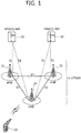
- FIG. 1 shows LTE system architecture.
- the communication network is widely deployed to provide a variety of communication services such as voice over internet protocol (VoIP) through IMS and packet data.
- VoIP voice over internet protocol
- the LTE system architecture includes one or more user equipment (UE; 10), an evolved-UMTS terrestrial radio access network (E-UTRAN) and an evolved packet core (EPC).
- the UE 10 refers to a communication equipment carried by a user.
- the UE 10 may be fixed or mobile, and may be referred to as another terminology, such as a mobile station (MS), a user terminal (UT), a subscriber station (SS), a wireless device, etc.
- MS mobile station
- UT user terminal
- SS subscriber station
- wireless device etc.
- the E-UTRAN includes one or more evolved node-B (eNB) 20, and a plurality of UEs may be located in one cell.
- the eNB 20 provides an end point of a control plane and a user plane to the UE 10.
- the eNB 20 is generally a fixed station that communicates with the UE 10 and may be referred to as another terminology, such as a base station (BS), an access point, etc.
- BS base station
- One eNB 20 may be deployed per cell.
- a downlink (DL) denotes communication from the eNB 20 to the UE
- an uplink (UL) denotes communication from the UE 10 to the eNB 20.
- a transmitter may be a part of the eNB 20, and a receiver may be a part of the UE 10.
- the transmitter may be a part of the UE 10, and the receiver may be a part of the eNB 20.
- the EPC includes a mobility management entity (MME) and a system architecture evolution (SAE) gateway (S-GW).
- MME mobility management entity
- SAE system architecture evolution gateway
- the MME/S-GW 30 may be positioned at the end of the network and connected to an external network.
- MME/S-GW 30 will be referred to herein simply as a "gateway,” but it is understood that this entity includes both the MME and S-GW.
- the MME provides various functions including non-access stratum (NAS) signaling to eNBs 20, NAS signaling security, access stratum (AS) security control, inter core network (CN) node signaling for mobility between 3GPP access networks, idle mode UE reachability (including control and execution of paging retransmission), tracking area list management (for UE in idle and active mode), packet data network (PDN) gateway (P-GW) and S-GW selection, MME selection for handovers with MME change, serving GPRS support node (SGSN) selection for handovers to 2G or 3G 3GPP access networks, roaming, authentication, bearer management functions including dedicated bearer establishment, support for public warning system (PWS) (which includes earthquake and tsunami warning system (ETWS) and commercial mobile alert system (CMAS)) message transmission.
- PWS public warning system
- ETWS earthquake and tsunami warning system
- CMAS commercial mobile alert system
- the S-GW host provides assorted functions including per-user based packet filtering (by e.g., deep packet inspection), lawful interception, UE Internet protocol (IP) address allocation, transport level packet marking in the DL, UL and DL service level charging, gating and rate enforcement, DL rate enforcement based on access point name aggregate maximum bit rate (APN-AMBR).
- per-user based packet filtering by e.g., deep packet inspection
- IP Internet protocol
- transport level packet marking in the DL transport level packet marking in the DL
- UL and DL service level charging e.g., gating and rate enforcement
- DL rate enforcement based on access point name aggregate maximum bit rate (APN-AMBR).
- APN-AMBR access point name aggregate maximum bit rate
- Interfaces for transmitting user traffic or control traffic may be used.
- the UE 10 is connected to the eNB 20 via a Uu interface.
- the eNBs 20 are connected to each other via an X2 interface.
- Neighboring eNBs may have a meshed network structure that has the X2 interface.
- a plurality of nodes may be connected between the eNB 20 and the gateway 30 via an S1 interface.
- FIG. 2 shows a block diagram of architecture of a typical E-UTRAN and a typical EPC.
- the eNB 20 may perform functions of selection for gateway 30, routing toward the gateway 30 during a radio resource control (RRC) activation, scheduling and transmitting of paging messages, scheduling and transmitting of broadcast channel (BCH) information, dynamic allocation of resources to the UEs 10 in both UL and DL, configuration and provisioning of eNB measurements, radio bearer control, radio admission control (RAC), and connection mobility control in LTE_ACTIVE state.
- gateway 30 may perform functions of paging origination, LTE_IDLE state management, ciphering of the user plane, SAE bearer control, and ciphering and integrity protection of NAS signaling.
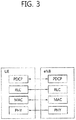
- FIG. 3 shows a block diagram of a user plane protocol stack of an LTE system.
- FIG. 4 shows a block diagram of a control plane protocol stack of an LTE system.
- Layers of a radio interface protocol between the UE and the E-UTRAN may be classified into a first layer (LI), a second layer (L2), and a third layer (L3) based on the lower three layers of the open system interconnection (OSI) model that is well-known in the communication system.
- LI first layer
- L2 second layer
- L3 third layer
- a physical (PHY) layer belongs to the L1.
- the PHY layer provides a higher layer with an information transfer service through a physical channel.
- the PHY layer is connected to a medium access control (MAC) layer, which is a higher layer of the PHY layer, through a transport channel.
- MAC medium access control
- a physical channel is mapped to the transport channel. Data between the MAC layer and the PHY layer is transferred through the transport channel.
- PHY physical
- a MAC layer, a radio link control (RLC) layer, and a packet data convergence protocol (PDCP) layer belong to the L2.
- the MAC layer provides services to the RLC layer, which is a higher layer of the MAC layer, via a logical channel.
- the MAC layer provides data transfer services on logical channels.
- the RLC layer supports the transmission of data with reliability. Meanwhile, a function of the RLC layer may be implemented with a functional block inside the MAC layer. In this case, the RLC layer may not exist.
- the PDCP layer provides a function of header compression function that reduces unnecessary control information such that data being transmitted by employing IP packets, such as IPv4 or IPv6, can be efficiently transmitted over a radio interface that has a relatively small bandwidth.
- a radio resource control (RRC) layer belongs to the L3.
- the RLC layer is located at the lowest portion of the L3, and is only defined in the control plane.
- the RRC layer controls logical channels, transport channels, and physical channels in relation to the configuration, reconfiguration, and release of radio bearers (RBs).
- the RB signifies a service provided the L2 for data transmission between the UE and E-UTRAN.
- the RLC and MAC layers may perform functions such as scheduling, automatic repeat request (ARQ), and hybrid ARQ (HARQ).
- the PDCP layer may perform the user plane functions such as header compression, integrity protection, and ciphering.
- the RLC and MAC layers may perform the same functions for the control plane.
- the RRC layer (terminated in the eNB on the network side) may perform functions such as broadcasting, paging, RRC connection management, RB control, mobility functions, and UE measurement reporting and controlling.
- the NAS control protocol (terminated in the MME of gateway on the network side) may perform functions such as a SAE bearer management, authentication, LTE_IDLE mobility handling, paging origination in LTE_IDLE, and security control for the signaling between the gateway and UE.
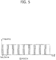
- FIG. 5 shows an example of a physical channel structure.
- a physical channel transfers signaling and data between PHY layer of the UE and eNB with a radio resource.
- a physical channel consists of a plurality of subframes in time domain and a plurality of subcarriers in frequency domain.
- One subframe which is 1 ms, consists of a plurality of symbols in the time domain.
- Specific symbol(s) of the subframe such as the first symbol of the subframe, may be used for a physical downlink control channel (PDCCH).
- the PDCCH carries dynamic allocated resources, such as a physical resource block (PRB) and modulation and coding scheme (MCS).
- PRB physical resource block
- MCS modulation and coding scheme
- a DL transport channel includes a broadcast channel (BCH) used for transmitting system information, a paging channel (PCH) used for paging a UE, a downlink shared channel (DL-SCH) used for transmitting user traffic or control signals, a multicast channel (MCH) used for multicast or broadcast service transmission.
- BCH broadcast channel
- PCH paging channel
- DL-SCH downlink shared channel
- MCH multicast channel
- the DL-SCH supports HARQ, dynamic link adaptation by varying the modulation, coding and transmit power, and both dynamic and semi-static resource allocation.
- the DL-SCH also may enable broadcast in the entire cell and the use of beamforming.
- a UL transport channel includes a random access channel (RACH) normally used for initial access to a cell, a uplink shared channel (UL-SCH) for transmitting user traffic or control signals, etc.
- RACH random access channel
- UL-SCH uplink shared channel
- the UL-SCH supports HARQ and dynamic link adaptation by varying the transmit power and potentially modulation and coding.
- the UL-SCH also may enable the use of beamforming.
- the logical channels are classified into control channels for transferring control plane information and traffic channels for transferring user plane information, according to a type of transmitted information. That is, a set of logical channel types is defined for different data transfer services offered by the MAC layer.
- the control channels are used for transfer of control plane information only.
- the control channels provided by the MAC layer include a broadcast control channel (BCCH), a paging control channel (PCCH), a common control channel (CCCH), a multicast control channel (MCCH) and a dedicated control channel (DCCH).
- the BCCH is a downlink channel for broadcasting system control information.
- the PCCH is a downlink channel that transfers paging information and is used when the network does not know the location cell of a UE.
- the CCCH is used by UEs having no RRC connection with the network.
- the MCCH is a point-to-multipoint downlink channel used for transmitting multimedia broadcast multicast services (MBMS) control information from the network to a UE.
- the DCCH is a point-to-point bi-directional channel used by UEs having an RRC connection that transmits dedicated control information between a UE and the network.
- Traffic channels are used for the transfer of user plane information only.
- the traffic channels provided by the MAC layer include a dedicated traffic channel (DTCH) and a multicast traffic channel (MTCH).
- DTCH dedicated traffic channel
- MTCH multicast traffic channel
- the DTCH is a point-to-point channel, dedicated to one UE for the transfer of user information and can exist in both uplink and downlink.
- the MTCH is a point-to-multipoint downlink channel for transmitting traffic data from the network to the UE.
- Uplink connections between logical channels and transport channels include the DCCH that can be mapped to the UL-SCH, the DTCH that can be mapped to the UL-SCH and the CCCH that can be mapped to the UL-SCH.
- Downlink connections between logical channels and transport channels include the BCCH that can be mapped to the BCH or DL-SCH, the PCCH that can be mapped to the PCH, the DCCH that can be mapped to the DL-SCH, and the DTCH that can be mapped to the DL-SCH, the MCCH that can be mapped to the MCH, and the MTCH that can be mapped to the MCH.
- An RRC state indicates whether an RRC layer of the UE is logically connected to an RRC layer of the E-UTRAN.
- the RRC state may be divided into two different states such as an RRC idle state (RRC_IDLE) and an RRC connected state (RRC_CONNECTED).
- RRC_IDLE the UE may receive broadcasts of system information and paging information while the UE specifies a discontinuous reception (DRX) configured by NAS, and the UE has been allocated an identification (ID) which uniquely identifies the UE in a tracking area and may perform public land mobile network (PLMN) selection and cell re-selection.
- ID identification
- PLMN public land mobile network
- the UE In RRC_CONNECTED, the UE has an E-UTRAN RRC connection and a context in the E-UTRAN, such that transmitting and/or receiving data to/from the eNB becomes possible. Also, the UE can report channel quality information and feedback information to the eNB.
- the E-UTRAN knows the cell to which the UE belongs. Therefore, the network can transmit and/or receive data to/from UE, the network can control mobility (handover and inter-radio access technologies (RAT) cell change order to GSM EDGE radio access network (GERAN) with network assisted cell change (NACC)) of the UE, and the network can perform cell measurements for a neighboring cell.
- RAT inter-radio access technologies
- GERAN GSM EDGE radio access network
- NACC network assisted cell change
- the UE specifies the paging DRX cycle. Specifically, the UE monitors a paging signal at a specific paging occasion of every UE specific paging DRX cycle.
- the paging occasion is a time interval during which a paging signal is transmitted.
- the UE has its own paging occasion.
- a paging message is transmitted over all cells belonging to the same tracking area. If the UE moves from one tracking area (TA) to another TA, the UE will send a tracking area update (TAU) message to the network to update its location.
- TAU tracking area update
- the E-UTRAN may support dual connectivity operation whereby a multiple RX/TX UE in RRC_CONNECTED is configured to utilize radio resources provided by two distinct schedulers, located in two eNBs connected via a non-ideal backhaul over the X2 interface.
- the overall E-UTRAN architecture described in FIG. 1 is applicable for dual connectivity as well. Two different roles may be assumed to eNBs involved in dual connectivity for a certain UE: an eNB may either act as a master eNB (MeNB) or as a secondary eNB (SeNB).
- the MeNB is the eNB which terminates at least S1-MME in dual connectivity.
- the SeNB is the eNB that is providing additional radio resources for the UE but is not the MeNB in dual connectivity. In dual connectivity a UE is connected to one MeNB and one SeNB.
- FIG. 6 shows radio protocol architecture for dual connectivity.
- the radio protocol architecture that a particular bearer uses depends on how the bearer is setup.
- Three alternatives exist master cell group (MCG) bearer, secondary cell group (SCG) bearer and split bearer. Referring to FIG. 6 , those three alternatives are depicted, i.e. in order of the MCG bearer, split bearer and SCG bearer from left to right.
- MCG bearer is a bearer whose radio protocols are only located in the MeNB to use MeNB resources only in dual connectivity.
- the SCG bearer is a bearer whose radio protocols are only located in the SeNB to use SeNB resources in dual connectivity.
- the split bearer is a bearer whose radio protocols are located in both the MeNB and the SeNB to use both MeNB and SeNB resources in dual connectivity.
- Signaling radio bearers (SRBs) are always of the MCG bearer and therefore only use the radio resources provided by the MeNB.
- the MCG is a group of serving cells associated with the MeNB, comprising of the primary cell (PCell) and optionally one or more secondary cells (SCells) in dual connectivity.
- the SCG is a group of serving cells associated with the SeNB, comprising of primary SCell (PSCell) and optionally one or more SCells in dual connectivity.
- DC may also be described as having at least one bearer configured to use radio resources provided by the SeNB.
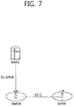
- FIG. 7 shows C-plane connectivity of eNBs involved in dual connectivity for a certain UE.
- Inter-eNB control plane signaling for dual connectivity is performed by means of X2 interface signaling.
- Control plane signaling towards the MME is performed by means of S1 interface signaling.
- Each eNB should be able to handle UEs independently, i.e. provide the PCell to some UEs while providing SCell(s) for SCG to others.
- Each eNB involved in dual connectivity for a certain UE owns its radio resources and is primarily responsible for allocating radio resources of its cells, respective coordination between MeNB and SeNB is performed by means of X2 interface signaling.
- the MeNB is C-plane connected to the MME via S1-MME
- the MeNB and the SeNB are interconnected via X2-C.
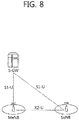
- FIG. 8 shows U-plane connectivity of eNBs involved in dual connectivity for a certain UE.
- U-plane connectivity depends on the bearer option configured.
- the MeNB is U-plane connected to the S-GW via S1-U
- the SeNB is not involved in the transport of user plane data.
- the MeNB is U-plane connected to the S-GW via S1-U and in addition, the MeNB and the SeNB are interconnected via X2-U.
- SCG bearers the SeNB is directly connected with the S-GW via S1-U. If only MCG and split bearers are configured, there is no S1-U termination in the SeNB.
- FIG. 9 shows an example of U-plane architecture for dual connectivity.
- U-plane architecture for dual connectivity shown in FIG. 9 is the combination of S1-U that terminates in SeNB and independent PDCPs (no bearer split).
- FIG. 10 shows another example of U-plane architecture for dual connectivity.
- U-plane architecture for dual connectivity shown in FIG. 10 is the combination of S1-U that terminates in MeNB, bearer split in MeNB, and independent RLCs for split bearers.
- the corresponding UE architecture may be also changed to support the new feature.
- FIG. 11 shows an example of an X2 handover procedure for dual connectivity enhancement.
- FIG. 11 shows an example signaling flow for a MeNB to eNB change procedure, which is used to transfer context data from a source MeNB (S-MeNB)/SeNB to a target eNB (T-eNB).
- S-MeNB source MeNB
- T-eNB target eNB
- step S1110 the source MeNB starts the MeNB to eNB change procedure by initiating the X2 handover preparation procedure, i.e. transmitting the Handover Request message to the target eNB.
- the source MeNB includes the SCG configuration in the HandoverPreparationInformation.
- Table 1 shows the Handover Request message. This message is sent by the source eNB to the target eNB to request the preparation of resources for a handover.
- OCTET STRING Includes the RRC Handover Preparation Information message as defined in subclause 10.2.2 of TS 36.331 [9] - - >Handover Restriction List O 9.2.3 - - >Location Reporting Information O 9.2.21 Includes the necessary parameters for location reporting - - >Management Based MDT Allowed O 9.2.59 YES ignore >Management Based MDT PLMN List O MDT PLMN List 9.2.64 YES ignore UE History Information M 9.2.38 Same definition as in TS 36.413 [4] YES ignore Trace Activation O 9.2.2 YES ignore SRVCC Operation Possible O 9.2.33 YES ignore CSG Membership Status O 9.2.52 YES reject Mobility Information O BIT STRING (SIZE (32)) Information related to the handover; the source eNB provides it in order to enable later analysis of the conditions that led to a wrong HO.
- SIZE SIZE
- the target eNB transmits the Handover Request Acknowledge message to the source MeNB.
- the target eNB includes the field in handover command which releases SCG configuration, and may also provide forwarding addresses to the source MeNB.
- the addition of a SeNB can be initiated only after completing handover.
- Table 2 shows the Handover Request Acknowledge message. This message is sent by the target eNB to inform the source eNB about the prepared resources at the target.
- E-RAB ID Identifies the X2 transport bearer used for forwarding of UL PDUs - - >>DL GTP Tunnel Endpoint O GTP Tunnel Endpoint 9.2.1 Identifies the X2 transport bearer. used for forwarding of DL PDUs - - E-RABs Not Admitted List O E-RAB List 9.2.28
- a value for E-RAB ID shall only be present once in E-RABs Admitted List IE and in E-RABs Not Admitted List IE.
- step S1110 if the allocation of target eNB resources was successful, the MeNB initiates the release of the source SeNB resources towards the source SeNB by transmitting the SeNB Release Request message. If data forwarding is needed, the MeNB provides data forwarding addresses to the source SeNB. Either direct data forwarding or indirect data forwarding is used for SCG bearer. Only indirect data forwarding is used for split bearer. Reception of the SeNB Release Request message triggers the source SeNB to stop providing user data to the UE and, if applicable, to start data forwarding. Table 3 shows the SeNB Release Request message. This message is sent by the MeNB to the SeNB to request the release of resources.
- step S1120 the MeNB triggers the UE to apply the new configuration by transmitting the RRCConnectionReconfiguration message to the UE. Upon receiving the new configuration, the UE releases the entire SCG configuration.
- the UE synchronizes to the target eNB.
- the UE performs random access procedure with the target eNB.
- the UE transmits the RRCConnectionReconfigurationComplete message to the target eNB.
- step S1140 sequence number (SN) Status Transfer message may be exchanged between the source MeNB and SeNB/target eNB.
- step S1141 data forwarding from the SeNB takes place for E-UTRAN radio access bearers (E-RABs) configured with the SCG bearer option. It may start as early as the source SeNB receives the SeNB Release Request message from the MeNB.
- E-RABs E-UTRAN radio access bearers
- the target eNB initiates the S1 path switch procedure.
- the target eNB may transmit the Path Switch Request message to the MME.
- the MME may perform the bearer modification procedure with the S-GW.
- the end marker packet may be transmitted from the S-GW, via the source MeNB, to the target eNB.
- the new packets may be transmitted from the S-GW to the target eNB.
- the MME may transmit Path Switch Request Acknowledge message to the target eNB.
- step S1160 the target eNB initiates the UE context release procedure towards the source MeNB.
- step S1161 upon reception of the UE Context Release message, the SeNB can release radio and C-plane related resource associated to the UE context. Any ongoing data forwarding may continue.
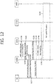
- FIG. 12 shows an example of a SeNB addition procedure.
- the SeNB addition procedure is initiated by the MeNB and is used to establish a UE context at the SeNB in order to provide radio resources from the SeNB to the UE.
- This procedure is used to add at least the first cell (PSCell) of the SCG.
- PSCell first cell
- the MeNB decides to request the SeNB to allocate radio resources for a specific E-RAB, indicating E-RAB characteristics (E-RAB parameters, TNL address information corresponding to the UP option).
- E-RAB characteristics E-RAB parameters, TNL address information corresponding to the UP option.
- MeNB indicates within SCG-ConfigInfo the MCG configuration (including security algorithm for SCG bearer) and the entire UE capabilities for UE capability coordination to be used as basis for the reconfiguration by the SeNB, but does not include SCG configuration.
- the MeNB can provide the latest measurement results for the SCG cell(s) requested to be added.
- the SeNB may reject the request.
- Table 4 shows the SeNB Addition Request message. This message is sent by the MeNB to the SeNB to request the preparation of resources for dual connectivity operation for a specific UE.
- YES reject SeNB UE Aggregate Maximum Bit Rate M UE Aggregate Maximum Bit Rate 9.2.12
- the UE Aggregate Maximum Bit Rate is split into MeNB UE Aggregate Maximum Bit Rate and SeNB UE Aggregate Maximum Bit Rate which are enforced by MeNB and SeNB respectively.
- step S1201 if the radio resource management (RRM) entity in the SeNB is able to admit the resource request, it allocates respective radio resources and, dependent on the bearer option, respective transport network resources.
- the SeNB triggers random access so that synchronization of the SeNB radio resource configuration can be performed.
- the SeNB provides the new radio resource of SCG in SCG-Config to the MeNB. For SCG bearers, together with S1 DL TNL address information for the respective E-RAB and security algorithm, for split bearers X2 DL TNL address information.
- step S1210 if the MeNB endorses the new configuration, the MeNB sends the RRCConnectionReconfiguration message to the UE including the new radio resource configuration of SCG according to the SCG-Config.
- step S1211 the UE applies the new configuration and replies with RRCConnectionReconfigurationComplete message. In case the UE is unable to comply with (part of) the configuration included in the RRCConnectionReconfiguration message, it performs the reconfiguration failure procedure.
- step S1220 the MeNB informs the SeNB that the UE has completed the reconfiguration procedure successfully.
- step S1230 the UE performs synchronization towards the PSCell of the SeNB.
- the order the UE sends the RRCConnectionReconfigurationComplete message and performs the random access procedure towards the SCG is not defined.
- the successful RA procedure towards the SCG is not required for a successful completion of the RRC Connection Reconfiguration procedure.
- the MeNB may take actions to minimize service interruption due to activation of dual connectivity (Data forwarding, SN Status transfer).
- step S1250 for SCG bearers, the update of the UP path towards the EPC is performed.
- FIG. 13 shows an example of a deployment scenario with a common SeNB shared by two MeNBs.
- a UE is receiving dual connectivity service via bearer 1 from MeNB 1, and via bearer 2 from SeNB.
- the UE may be handed over to the neighbor MeNB, i.e. MeNB 2, which shares the SeNB with the MeNB 1.
- the SeNB shared by two MeNBs has to be released from MeNB 1 first, and the target MeNB, i.e. MeNB 2, may add the SeNB again after X2 handover. That is, the SeNB addition procedure shown in FIG. 12 has to be performed again. This may not be the optimized procedure.
- FIG. 14 shows a method for exchanging information about whether a common SeNB exists between MeNBs according to an embodiment of the present invention.
- the eNB 1 transmits the X2 Setup Request message, which includes a specific indicator for specific serving cells of the eNB 1, to the eNB 2.
- the specific indicator may contain cell IDs of the specific overlapping serving cells.
- the specific indicator may further indicate that the specific serving cells provide dual connectivity service.
- the specific serving cells may correspond to potential SeNBs shared with the eNB 2.
- the eNB 2 replies to the eNB 1 by transmitting the X2 Setup Response message, which also includes a specific indicator for specific serving cells of the eNB 2.
- the specific indicator may contain cell IDs of the specific overlapping serving cells.
- the specific indicator may further indicate that the specific serving cells provide dual connectivity service.
- the specific serving cells may correspond to potential SeNBs shared with the eNB 1.
- the eNB2 or eNB1 may check its own serving cells and compare them with the specific serving cells indicated by the specific indicator. Accordingly, the eNB 2 or eNB 1 may identify which cell is a common cell shared by neighbor eNBs and provides dual connectivity service.
- FIG. 15 shows a method for performing an inter-MeNB handover without SeNB change according to an embodiment of the present invention.
- the SeNB bearers or, SeNB E-RABs
- the UE may transmit the measurement report to the source MeNB, which makes a handover decision to the target MeNB for the UE.
- the source MeNB may also know that the UE is receiving a certain service from the SeNB, which is commonly controlled by the source MeNB and the target MeNB.
- the source MeNB transmits the Handover Request message, which includes a first indicator, to target MeNB.
- the first indicator may be indication of SeNB bearers and/or MeNB bearers.
- the target MeNB may differentiate the E-RABs To Be Setup List for the SeNB (i.e. SeNB bearers) and the E-RABs To Be Setup List for the MeNB (i.e. MeNB bearers).
- the target MeNB may know that the source MeNB has intention to keep the SeNB service/bearer.
- the first indicator may be realized by SeNB UE X2AP ID, which was allocated by the SeNB before handover is triggered.
- the first indicator may be an indicator of the SeNB to indicate the target MeNB which SeNB service/bearer is kept for this the UE.
- the first indicator may be a SeNB (cell) ID.
- the first indicator may be a list of potential candidate SeNBs for the target MeNB to select.
- the Handover Request message may include assistant information, i.e. measurement information, for the target MeNB to select the target SeNB.
- the measurement information may be contained in an independent IE in the Handover Request message.
- the measurement information may be contained in MeNB to SeNB Container including SCG-ConfigInfo , as measResultServCellListSCG indicating measurement results of SCG (serving) cells.
- the measurement information may be contained in RRC Context IE in the Handover Request Message.
- the first indicator may help the target MeNB to make a decision on how to keep the SeNB.
- Table 5 shows an example of the Handover Request message according to an embodiment of the present invention.
- ⁇ Table 5> IE/Group Name Presence Range IE type and reference Semantics description Criticality Assigned Criticality Message Type
- OCTET STRING Includes the RRC Handover Preparation Information message as defined in subclause 10.2.2 of TS 36.331 [9] It may also contain the measurement results of SCG (serving) cells, details are defined in TS 36.331 - - >Handover Restriction List O 9.2.3 - - > Location Reporting Information O 9.2.21 Includes the necessary parameters for location reporting - - >Management Based MDT Allowed O 9.2.59 YES ignore >Management Based MDT PLMN List O MDT PLMN List 9.2.64 YES ignore UE History Information M 9.2.38 Same definition as in TS 36.413 [4] YES ignore Trace Activation O 9.2.2 YES ignore SRVCC Operation Possible O 9.2.33 YES ignore CSG Membership Status O 9.2.52 YES reject Mobility Information O BIT STRING (SIZE (32)) Information related to the handover; the source eNB provides it in order to enable later analysis of the conditions that led to a wrong HO.
- SIZE SIZE
- the specific indicator of SeNB UE X2AP ID may be added in the Handover Request message.
- the specific indicator of SeNB UE X2AP ID may indicate that the source MeNB has intention to keep the SeNB service/bearer. Further, the specific indicator of measurements results of SCG cells may be added in the Handover Request message. Further, the specific indicator of SeNB ID or list of candidate SeNB IDs may be added in the Handover Request message.
- the target MeNB may know that the SeNB service/bearer should be kept. Then, in step S1510, the target MeNB transmits the SeNB Addition/Modification Request message, which includes a second indicator, to the SeNB.
- the second indicator may indicate the SeNB that the requested bearers (with IDs) are currently served by the SeNB. That is, the second indicator may provide the SeNB with the meaning that the SeNB has to accept all of the corresponding bearers or partially.
- the second indicator may further include the updated security key, generated by the target MeNB, for the SeNB bearers.
- the second indicator may help the SeNB to know that the UE was served by the SeNB before handover is triggered. That is, the second indicator may indicate the SeNB so that the SeNB can identify the UE.
- the second indicator may be realized by the old SeNB UE X2AP ID, which was allocated by the SeNB on the source MeNB side during the addition procedure.
- the source MeNB ID may be added in the SeNB Addition Request message in order to help the SeNB to identify the UE.
- the source MeNB ID may help to avoid the situation that X2AP ID was implemented per interface instead of per node.
- Table 6 shows an example of the SeNB Addition Request message according to an embodiment of the present invention.
- Table 6 IE/Group Name Presence Range IE type and reference Semantics description Criticality Assigned Criticality Message Type M 9.2.13 YES reject MeNB UE X2AP ID M eNB UE X2AP ID 9.2.24 Allocated at the MeNB YES reject UE Security Capabilities C-ifSCG Bearer Option 9.2.29 YES reject SeNB Security Key C-ifSCG Bearer Option 9.2.72
- the S-KeNB which is provided by the MeNB, see TS 33.401 [18].
- the UE Aggregate Maximum Bit Rate is split into MeNB UE Aggregate Maximum Bit Rate and SeNB UE Aggregate Maximum Bit Rate which are enforced by MeNB and SeNB respectively.
- the old SeNB UE X2AP ID and the source MeNB ID may be added in the SeNB Addition Request message.
- the old SeNB UE X2AP ID may correspond to the second indicator.
- the old SeNB UE X2AP ID may be allocated by the SeNB on the source MeNB side during the addition procedure.
- the SeNB gives a response with the SeNB Addition/Modification Request Acknowledge message, which includes a third indicator.
- the third indicator may indicate whether the original SeNB bearers are all accepted or partially accepted. That is, the third indicator may indicate information on which specific SeNB bearer is accepted and which specific SeNB bearer is not accepted.
- the target MeNB may accept the rejected SeNB bearer and put in the accepted MeNB bearers list, which is described in step S1520 below.
- the target MeNB transmit the Handover Request Acknowledge message, which includes a fourth indicator, to the source MeNB.
- the fourth indicator may be indication of SeNB bearers and/or MeNB bearers.
- the fourth indicator may indicate the accepted SeNB bearers and/or rejected SeNB bearers, which are the SeNB bearers within the requested list.
- the fourth indicator may further indicate the accepted MeNB bearers and/or rejected MeNB bearers. As described above, if the rejected SeNB bearer exists, the accepted MeNB bearers may include the rejected SeNB bearer.
- the fourth indicator may further indicate whether the request of keeping the SeNB bearers are accepted or partially accepted.
- the fourth indicator may indicate the source MeNB clearly whether the SeNB is kept or not.
- the fourth indicator may indicate to the source MeNB for release handling.
- Table 7 shows an example of the Handover Request Acknowledge message according to the embodiment of the present invention.
- Table 7 > IE/Group Name Presence Range IE type and reference Semantics description Criticality Assigned Criticality Message Type M 9.2.13 YES reject Old eNB UE X2AP ID M eNB UE X2AP ID 9.2.24 Allocated at the source eNB YES ignore New eNB UE X2AP ID M eNB UE X2AP ID 9.2.24 Allocated at the target eNB YES ignore E-RABs Admitted List 1 YES ignore > E-RABs Admitted Item 1 ..
- E-RAB ID Identifies the X2 transport bearer used for forwarding of UL PDUs - - >>DL GTP Tunnel Endpoint O GTP Tunnel Endpoint 9.2.1 Identifies the X2 transport bearer. used for forwarding of DL PDUs - - E-RABs Not Admitted List O E-RAB List 9.2.28
- a value for E-RAB ID shall only be present once in E-RABs Admitted List IE and in E-RABs Not Admitted List IE.
- OCTET STRING Includes the RRC E-UTRA Handover Command message as defined in subclause 10.2.2 in TS 36.331 [9] YES ignore Criticality Diagnostics O 9.2.7 YES ignore Indicator of successful SeNB Keeping O YES ignore
- the indicator of successful SeNB keeping is further added.
- the indicator of successful SeNB keeping may correspond to the fourth indicator.
- the source MeNB may transmit the SeNB Modification Request message or SeNB Release Request message to the SeNB.
- the SeNB Modification Request message may be transmitted when partial SeNB bearers are accepted.
- the SeNB Release Request message may be transmitted when all SeNB bearers are rejected.
- the SeNB Modification Request message or SeNB Release Request message may include a fifth indicator.
- the fifth indicator may indicate that each SeNB bearer is to be kept in the SeNB.
- the fifth indicator may further indicate that each SeNB bearer is to be handed over to the target MeNB.
- the fifth indicator may further indicate the SeNB that only the X2 interface related resources, instead of radio resources, are released in case keeping is successful.
- the fifth indicator may indicate to the SeNB for release handling.
- the fifth indicator may clearly indicate the SeNB the bearers to be kept in the SeNB through IP address of the SeNB and GPRS tunneling protocol (GTP) tunnel endpoint ID (TEID) allocated by the SeNB and the bearers to be handed over to the target MeNB through IP address of the MeNB and GTP TEID allocated by the MeNB.
- GTP GPRS tunneling protocol
- Table 8 shows an example of the SeNB Release Request message according to the embodiment of the present invention.
- Table 8> IE/Group Name Presence Range IE type and reference Semantics description Criticality Assigned Criticality Message Type M 9.2.13 YES ignore MeNB UE X2AP ID M eNB UE X2AP ID Allocated at the MeNB YES reject 9.2.24 SeNB UE X2AP ID O eNB UE X2AP ID Allocated at the SeNB YES reject 9.2.24 Cause O 9.2.6 YES ignore E-RABs To Be Released List 0..1 - - > E-RABs To Be Released Item 1 ..
- the indicator of releasing only X2 related resource is further added.
- the indicator of releasing only X2 related resource may correspond to the fifth indicator.
- the source MeNB may transmit the RRCConnectionReconfiguration message to the UE with the updated MeNB and SeNB configuration. And, the random access may be performed, and the UE may transmit the RRCConnectionReconfigurationComplete message to the target MeNB.
- step S1530 the target MeNB transmits the SeNB Reconfiguration Complete message to the SeNB for confirmation.
- the SeNB may transmit the SN Status Transfer message to the source MeNB for the partial SeNB bearers (with indicator), for which the data forwarding is needed.
- the source MeNB may transmit the SN Status Transfer message to the target MeNB for the MeNB bearers (with indicator), and also for the partial SeNB bearers of step S1540.
- data forwarding may be initiated for the MeNB bearers and the partial SeNB bearers.
- the target MeNB may transmit the Path Switch Request message or E-RAB Modification Indication message to the MME for bearer path change.
- the Path Switch Request message or E-RAB Modification Indication message may include an indication of E-RABs to be modified and E-RABs not to be modified.
- the Path Switch Request message or E-RAB Modification Indication message may further include an indication of E-RABs for the MeNB and E-RABs for the SeNB which keeps the SeNB bearers.
- the S-GW and MME may perform bearer modification for bearer information updates by exchanging the Modify Bearer Request/Response messages.
- the Modify Bearer Request/Response messages may include an indication of bearers to be modified and bearers not to be modified.
- step S1570 the end marker may be transmitted.
- step S1571 the new packets may be transmitted.
- the MME may transmit the Path Switch Request Acknowledge message or E-RAB Modification Confirmation message to the target MeNB for response of bearer path change.
- the Path Switch Request Acknowledge message or E-RAB Modification Confirmation message may include an indication of E-RABs modified and E-RABs failed to modify.
- the Path Switch Request Acknowledge message or E-RAB Modification Confirmation message may further include information of MeNB bearers or SeNB bearers.
- step S1590 the target MeNB transmits the UE Context Release message to the source MeNB to release the UE context.
- the source MeNB may transmit the UE Context Release message to the SeNB if all of the SeNB bearers are rejected in step S1511 described above.
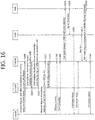
- FIG. 16 shows a method for performing an inter-MeNB handover without SeNB change according to an embodiment of the present invention.
- the SeNB bearers or, SeNB E-RABs
- the UE may transmit the measurement report to the source MeNB, which makes a handover decision to the target MeNB for the UE.
- the source MeNB may also know that the UE is receiving a certain service from the SeNB, which is commonly controlled by the source MeNB and the target MeNB.
- the source MeNB transmits the Handover Request message, which includes a first indicator, to target MeNB.
- the first indicator may be indication of SeNB bearers and/or MeNB bearers.
- the target MeNB may differentiate the E-RABs To Be Setup List for the SeNB (i.e. SeNB bearers) and the E-RABs To Be Setup List for the MeNB (i.e. MeNB bearers).
- the target MeNB may know that the source MeNB has intention to keep the SeNB service/bearer.
- the first indicator may be an indicator of the SeNB, e.g. (cell) ID of the SeNB. In this case, the first indicator may indicate the target MeNB which SeNB service/bearer is kept for this the UE.
- the Handover Request message may follow Table 5 described above.
- the target MeNB may know that the SeNB service/bearer should be kept. Then, in step S1610, the target MeNB transmits the SeNB Addition/Modification Request message, which includes a second indicator, to the SeNB.
- the second indicator may indicate the SeNB that the requested bearers (with IDs) are currently served by the SeNB. That is, the second indicator may provide the SeNB with the meaning that the SeNB has to accept the corresponding bearers.
- the second indicator may further include the updated security key, generated by the target MeNB, for the SeNB bearers.
- the SeNB Addition Request message may follow Table 6 described above.
- the SeNB gives a response with the SeNB Addition/Modification Request Acknowledge message, which includes a third indicator.
- the third indicator may indicate whether the original SeNB bearers are accepted or not.
- the target MeNB transmit the Handover Request Acknowledge message, which includes a fourth indicator, to the source MeNB.
- the fourth indicator may be indication of SeNB bearers and/or MeNB bearers.
- the fourth indicator may indicate the accepted SeNB bearers, which are the SeNB bearers within the requested list.
- the fourth indicator may further indicate the accepted MeNB bearers and/or rejected MeNB bearers.
- the fourth indicator may further indicate whether the request of keeping the SeNB bearers are accepted or not.
- the Handover Request Acknowledge message may follow Table 7 described above.
- the source MeNB may transmit the RRCConnectionReconfiguration message to the UE with the updated MeNB and SeNB configuration. And, the random access may be performed, and the UE may transmit the RRCConnectionReconfigurationComplete message to the target MeNB.
- step S1630 the target MeNB transmits the SeNB Reconfiguration Complete message to the SeNB for confirmation.
- the source MeNB may transmit the SN Status Transfer message to the target MeNB only for the MeNB bearers (with indicator). Since the SeNB bearers are kept, data forwarding may not be needed for the SeNB bearers. In step S1641, data forwarding may be initiated for the MeNB bearers.
- the target MeNB may transmit the Path Switch Request message or E-RAB Modification Indication message to the MME for bearer path change.
- the Path Switch Request message or E-RAB Modification Indication message may include an indication of E-RABs to be modified and E-RABs not to be modified.
- the Path Switch Request message or E-RAB Modification Indication message may further include an indication of E-RABs for the MeNB and E-RABs for the SeNB which keeps the SeNB bearers.
- the S-GW and MME may perform bearer modification for bearer information updates by exchanging the Modify Bearer Request/Response messages.
- the Modify Bearer Request/Response messages may include an indication of bearers to be modified and bearers not to be modified.
- step S1670 the end marker may be transmitted.
- step S1671 the new packets may be transmitted.
- the MME may transmit the Path Switch Request Acknowledge message or E-RAB Modification Confirmation message to the target MeNB for response of bearer path change.
- the Path Switch Request Acknowledge message or E-RAB Modification Confirmation message may include an indication of E-RABs modified and E-RABs failed to modify.
- the Path Switch Request Acknowledge message or E-RAB Modification Confirmation message may further include information of MeNB bearers or SeNB bearers.
- step S1690 the target MeNB transmits the UE Context Release message to the source MeNB to release the UE context.
- FIG. 17 shows a method for performing an inter-MeNB handover without SeNB change according to an embodiment of the present invention.
- the source MeNB starts the handover procedure by initiating the X2 handover preparation procedure.
- the source MeNB includes the SCG configuration in the HandoverPreparationInformation.
- the source MeNB includes the SeNB UE X2AP ID and SeNB ID as a reference to the UE context in the SeNB that was established by the source MeNB in the Handover Request message.
- the handover request message may follow Table 5 described above.
- step S1700 if the target MeNB decides to keep the SeNB, the target MeNB sends SeNB Addition Request message to the SeNB including the SeNB UE X2AP ID as a reference to the UE context in the SeNB that was established by the source MeNB.
- the SeNB Addition Request message may follow Table 6 described above.
- step S1711 the SeNB replies with SeNB Addition Request Acknowledge message to the target MeNB.
- An indicator as the UE context kept in the SeNB may be introduced in the SeNB Addition Request Acknowledge message.
- the target MeNB includes within the Handover Request Acknowledge message a transparent container to be sent to the UE as an RRC message to perform the handover which also includes the SCG configuration, and may also provide forwarding addresses to the source MeNB.
- the target MeNB indicates to the source MeNB that the UE context in the SeNB is kept if the target MeNB and the SeNB decided to keep the UE context in the SeNB in step S1710 and S1711.
- the Handover Request Acknowledge message may follow Table 7 described above.
- the source MeNB sends the SeNB Release Request message to the SeNB.
- the source MeNB indicates to the SeNB that the UE context in SeNB is kept. If the indication as the UE context kept in SeNB is included, the SeNB keeps the UE context.
- the SeNB Release Request message may follow Table 8 described above.
- step S1740 the source MeNB triggers the UE to apply the new configuration.
- steps S1741 and S1742 the UE synchronizes to the target MeNB and replies with RRCConnectionReconfigurationComplete message.
- step S1743 the UE synchronizes to the SeNB.
- step S1750 if the RRC connection reconfiguration procedure was successful, the target MeNB informs the SeNB.
- steps S1760 and S1761 data forwarding from the source MeNB takes place.
- Data forwarding may be omitted for SCG bearers.
- Direct data forwarding from the source MeNB to the SeNB is not possible for split bearers.
- Direct data forwarding may occur only for bearer type change.
- the target MeNB initiates the S1 path switch procedure. If new UL TEIDs of the S-GW are included, the target MeNB performs MeNB initiated SeNB modification procedure to provide them to the SeNB.
- step S1780 the target MeNB initiates the UE context release procedure towards the source MeNB.
- step S1781 upon reception of the UE context release message, the SeNB can release C-plane related resource associated to the UE context towards the source MeNB. Any ongoing data forwarding may continue.
- the SeNB shall not release the UE context associated with the target MeNB if the indication was included in the SeNB Release Request in step S1730.
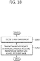
- FIG. 18 shows a method for performing, by a target MeNB, an inter-MeNB handover without SeNB change according to an embodiment of the present invention.
- a UE is connected to both the source MeNB and the SeNB currently, and the UE is to be handed over to the target MeNB by the handover procedure without change of the SeNB.
- step S1800 the target MeNB decides to keep bearers of the SeNB during inter-MeNB handover without SeNB change.
- step S1810 the target MeNB transmits a handover request acknowledge message including an indication of keeping the bearers of the SeNB to the source MeNB.
- Step S1810 may correspond to step S1520 in FIG. 15 , step S1620 in FIG. 16 , or step S1720 in FIG. 17 . That is, the handover request acknowledge message may follow Table 7 described above.
- the indication of keeping the bearers of the SeNB indicates that a UE context in the SeNB is kept.
- the indication of keeping the bearers of the SeNB may indicate whether a request of keeping the bearers of the SeNB are accepted or not.
- the indication of keeping the bearers of the SeNB may indicate whether the SeNB is kept or not.
- the target MeNB may further receive a handover request message from the source MeNB before deciding to keep the bearers of the SeNB.
- the handover request message may include an ID of the SeNB.
- FIG. 19 shows a method for performing, by a source MeNB, an inter-MeNB handover without SeNB change according to an embodiment of the present invention.
- a UE is connected to both the source MeNB and the SeNB currently, and the UE is to be handed over to the target MeNB by the handover procedure without change of the SeNB.
- step S1900 the source MeNB receives a handover request acknowledge message including a first indication of keeping bearers of the SeNB from a target MeNB in dual connectivity.
- Step S1900 may correspond to step S1520 in FIG. 15 , step S1620 in FIG. 16 , step S1720 in FIG. 17 , or step S1810 in FIG. 18 . That is, the handover request acknowledge message may follow Table 7 described above.
- the first indication of keeping the bearers of the SeNB may indicate that a UE context in the SeNB is kept.
- step S1910 the source MeNB transmits a SeNB release request message including a second indication of keeping the bearers of the SeNB to the SeNB.
- Step S1910 may correspond to step S1521 in FIG. 15 , or step S1730 in FIG. 17 . That is, the SeNB release request message may follow Table 8 described above.
- the second indication of keeping the bearers of the SeNB may indicate that a UE context in the SeNB is kept.
- the second indication of keeping the bearers of the SeNB may further indicate that only X2 interface related resources are released when the UE context in the SeNB is kept.
- the second indication of keeping the bearers of the SeNB may further indicate that the bearers in the SeNB is kept through an IP address of the SeNB and a GTP TEID allocated by the SeNB.
- the SeNB Upon receiving the SeNB release request message, the SeNB shall, if supported, only release the resources related to the UE-associated signaling connection between the MeNB and the SeNB.
- the source MeNB may further transmit a handover request message to the target MeNB before receiving the handover request acknowledge message.
- the handover request message may include an ID of the SeNB.
- FIG. 20 shows a method for performing an inter-MeNB handover without SeNB change according to an embodiment of the present invention.
- a UE is connected to both the source MeNB and the SeNB currently, and the UE is to be handed over to the target MeNB by the handover procedure without change of the SeNB.
- step S2000 the target MeNB decides to keep bearers of the SeNB during inter-MeNB handover without SeNB change.
- step S2010 the target MeNB transmits a handover request acknowledge message including a first indication of keeping the bearers of the SeNB to the source MeNB.
- Step S2010 may correspond to step S1520 in FIG. 15 , step S1620 in FIG. 16 , step S1720 in FIG. 17 , step S1810 in FIG. 18 , or step S1900 in FIG. 19 . That is, the handover request acknowledge message may follow Table 7 described above.
- the indication of keeping the bearers of the SeNB indicates that a UE context in the SeNB is kept.
- the indication of keeping the bearers of the SeNB may indicate whether a request of keeping the bearers of the SeNB are accepted or not.
- the indication of keeping the bearers of the SeNB may indicate whether the SeNB is kept or not.
- step S2020 the source MeNB transmits a SeNB release request message including a second indication of keeping the bearers of the SeNB to the SeNB.
- Step S2020 may correspond to step S1521 in FIG. 15 , step S1730 in FIG. 17 , or step S1910 in FIG. 19 . That is, the SeNB release request message may follow Table 8 described above.
- the second indication of keeping the bearers of the SeNB may indicate that a UE context in the SeNB is kept.
- the second indication of keeping the bearers of the SeNB may further indicate that only X2 interface related resources are released when the UE context in the SeNB is kept.
- the second indication of keeping the bearers of the SeNB may further indicate that the bearers in the SeNB is kept through an IP address of the SeNB and a GTP TEID allocated by the SeNB.
- the SeNB Upon receiving the SeNB release request message, the SeNB shall, if supported, only release the resources related to the UE-associated signaling connection between the MeNB and the SeNB.
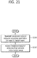
- FIG. 21 shows a method for performing, by a source MeNB, an inter-MeNB handover without SeNB change according to an embodiment of the present invention.
- a UE is connected to both the source MeNB and the SeNB currently, and the UE is to be handed over to the target MeNB by the handover procedure without change of the SeNB.
- the source MeNB transmits a handover request message including an indication of the SeNB to the target MeNB.
- Step S2100 may correspond to step S1500 in FIG. 15 , step S1600 in FIG. 16 , or step S1700 in FIG. 17 . That is, the handover request message may follow Table 5 described above.
- the indication of the SeNB corresponds to a SeNB ID. Or, the indication of the SeNB may correspond to a list of candidate SeNB IDs. Further, the indication of the SeNB may correspond to a SeNB UE X2AP ID, which was allocated by the SeNB. The SeNB UE X2AP ID may be allocated by the SeNB before the handover procedure is triggered.
- the handover request message may further include measurement results of SCG cells for the SeNB.
- step S2110 the source MeNB receives a handover request acknowledge message from the target MeNB.
- the handover request acknowledge message may include an indication of keeping bearers of the SeNB.
- Step S2110 may correspond to step S1520 in FIG. 15 , step S1620 in FIG. 16 , step S1720 in FIG. 17 , step S1810 in FIG. 18 , step S1900 in FIG. 19 , or step S2010 in FIG. 20 . That is, the handover request acknowledge message may follow Table 7 described above.
- FIG. 22 shows a method for performing, by a target MeNB, an inter-MeNB handover without SeNB change according to an embodiment of the present invention.
- a UE is connected to both the source MeNB and the SeNB currently, and the UE is to be handed over to the target MeNB by the handover procedure without change of the SeNB.
- step S2200 the target MeNB receives a handover request message including a first indication of the SeNB from the source MeNB.
- Step S2200 may correspond to step S1500 in FIG. 15 , step S1600 in FIG. 16 , step S1700 in FIG. 17 , or step S2100 in FIG. 21 . That is, the handover request message may follow Table 5 described above.
- the first indication of the SeNB may correspond to a SeNB ID.
- the target MeNB transmits a SeNB addition request message including a second indication of a UE, served by the SeNB, to the SeNB.
- Step S2210 may correspond to step S1510 in FIG. 15 , step S1610 in FIG. 16 , or step S1710 in FIG. 17 . That is, the SeNB addition request message may follow Table 6 described above.
- the second indication of the UE may correspond to an old SeNB UE X2AP ID, which was allocated by the SeNB.
- the SeNB addition request message may further include a source MeNB ID.
- the target MeNB may further receive a SeNB addition acknowledge message including a third indication of keeping bearers of the SeNB from the SeNB.
- the SeNB addition acknowledge message may correspond to step S1511 in FIG. 15 , step S1611 in FIG. 16 , or step S1711 in FIG. 17 .
- the third indication of keeping bearers of the SeNB may indicate which specific SeNB bearer is accepted or not.
- FIG. 23 shows a method for performing an inter-MeNB handover without SeNB change according to an embodiment of the present invention.
- a UE is connected to both the source MeNB and the SeNB currently, and the UE is to be handed over to the target MeNB by the handover procedure without change of the SeNB.
- step S2300 the source MeNB transmits a handover request message including a first indicator of the SeNB to the target MeNB.
- Step S2300 may correspond to step S1500 in FIG. 15 , step S1600 in FIG. 16 , step S1700 in FIG. 17 , step S2100 in FIG. 21 , or step S2200 in FIG. 22 . That is, the handover request message may follow Table 5 described above.
- the first indicator of the SeNB corresponds to a SeNB ID.
- the first indicator of the SeNB may correspond to a list of candidate SeNB IDs.
- the first indicator of the SeNB may correspond to a SeNB UE X2AP ID, which was allocated by the SeNB.
- the SeNB UE X2AP ID may be allocated by the SeNB before the handover procedure is triggered.
- step S2310 the target MeNB transmits a SeNB addition request message including a second indicator of a UE, served by the SeNB, to the SeNB.
- Step S2310 may correspond to step S1510 in FIG. 15 , step S1610 in FIG. 16 , step S1710 in FIG. 17 , or step S2210 in FIG. 22 . That is, the SeNB addition request message may follow Table 6 described above.
- the second indicator of the UE may correspond to an old SeNB UE X2AP ID, which was allocated by the SeNB.
- the SeNB transmits a SeNB addition acknowledge message including a third indicator of whether bearers of the SeNB are all accepted or partially accepted to the target MeNB.
- the SeNB addition acknowledge message may correspond to step S1511 in FIG. 15 , step S1611 in FIG. 16 , or step S1711 in FIG. 17 .
- FIG. 24 shows an example of a deployment scenario with two SeNBs and two MeNBs.
- SeNB 1 belongs to MeNB 1
- SeNB 2 belongs to MeNB 2.
- a UE is receiving dual connectivity service via bearer 1 from MeNB 1, and via bearer 2 from SeNB 1.
- the UE may be handed over to the neighbor MeNB, i.e. MeNB 2. If the current X2 handover procedure shown in FIG. 11 and the current SeNB addition procedure shown in FIG. 12 are applied to the deployment scenario shown in FIG. 24 , it is not optimized since the target MeNB has to add the SeNB again after X2 handover procedure. In this way, the path switch message to the MME and RRC signaling to the UE have to be transmitted twice.
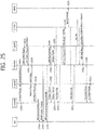
- FIG. 25 shows a method for performing an inter-MeNB handover according to an embodiment of the present invention. This embodiment is to solve the problem described in the deployment scenario in FIG. 24 . In this embodiment, direction addition to the neighbor SeNB during the handover may be assumed.
- the UE may transmit the measurement report to the source MeNB, which makes a handover decision to the target MeNB for the UE.
- the source MeNB transmits the Handover Request message, which includes a first indicator, to target MeNB.
- the first indicator may be indication of SeNB bearers and/or MeNB bearers.
- the target MeNB may differentiate the E-RABs To Be Setup List for the SeNB (i.e. SeNB bearers) and the E-RABs To Be Setup List for the MeNB (i.e. MeNB bearers).
- the first indicator may be an indicator of the SeNB to indicate the target MeNB to add directly.
- the first indicator may be a SeNB (cell) ID.
- the first indicator may be a list of potential candidate SeNBs for the target MeNB to select.
- the Handover Request message may include assistant information, i.e. measurement information, for the target MeNB to select the target SeNB.
- the measurement information may be contained in an independent IE in the Handover Request message.
- the measurement information may be contained in MeNB to SeNB Container including SCG-ConfigInfo , as measResultServCellListSCG indicating measurement results of SCG (serving) cells.
- the measurement information may be contained in RRC Context IE in the Handover Request Message.
- the Handover Request message may follow Table 5 described above.
- the target MeNB may know that the SeNB service/bearer may be added directly. Then, in step S2510, the target MeNB transmits the SeNB Addition Request message, which includes a second indicator, to the target SeNB.
- the second indicator may indicate the target SeNB bearers for the SeNB.
- the second indicator may further include the updated security key, generated by the target MeNB, for the SeNB bearers.
- the target SeNB gives a response with the SeNB Addition Request Acknowledge message, which includes a third indicator.
- the third indicator may indicate whether the SeNB bearers are all accepted or partially accepted. That is, the third indicator may indicate information on which specific SeNB bearer is accepted and which specific SeNB bearer is not accepted.
- the target MeNB may accept the rejected SeNB bearer and put in the accepted MeNB bearers list, which is described in step S2520 below.
- the target MeNB transmit the Handover Request Acknowledge message, which includes a fourth indicator, to the source MeNB.
- the fourth indicator may be indication of SeNB bearers and/or MeNB bearers.
- the fourth indicator may indicate the accepted SeNB bearers and/or rejected SeNB bearers, which are the SeNB bearers within the requested list.
- the fourth indicator may further indicate the accepted MeNB bearers and/or rejected MeNB bearers. As described above, if the rejected SeNB bearer exists, the accepted MeNB bearers may include the rejected SeNB bearer.
- the fourth indicator may further indicate direct data forwarding or indirect data forwarding.
- the source MeNB may transmit the SeNB Release Request message to the source SeNB.
- the SeNB Release Request message may include a fifth indicator.
- the fifth indicator may indicate that each SeNB bearer is to be handed over to the target MeNB and target SeNB.
- the fifth indicator may further indicate direct data forwarding or indirect data forwarding.
- the source MeNB transmits the RRCConnectionReconfiguration message to the UE with the updated MeNB and SeNB configuration, which may include the target MeNB configuration and/or target SeNB configuration.
- step S2541 and step S2542 the random access may be performed to the target MeNB and target SeNB, and the following will be RRCConnectionReconfigurationComplete message.
- step S2550 the target MeNB transmits the SeNB Reconfiguration Complete message to the target SeNB for confirmation.
- the source SeNB may transmit the SN Status Transfer message to the source MeNB for the bearers that data forwarding is needed.
- the source MeNB may transmit the SN Status Transfer message to the target MeNB, and partial may be forwarded to the target SeNB.
- step S2563 data forwarding may be initiated for the bearers in steps S2560, S2561 and S2562. Direct data forwarding may also be possible based on the indication.
- the target MeNB may transmit the Path Switch Request message or E-RAB Modification Indication message to the MME for bearer path change.
- the Path Switch Request message or E-RAB Modification Indication message may include an indication of E-RABs to be modified and E-RABs not to be modified.
- the Path Switch Request message or E-RAB Modification Indication message may further include an indication of E-RABs for the MeNB and E-RABs for the SeNB which keeps the SeNB bearers.
- the S-GW and MME may perform bearer modification for bearer information updates by exchanging the Modify Bearer Request/Response messages.
- the Modify Bearer Request/Response messages may include an indication of bearers to be modified and bearers not to be modified.
- the Modify Bearer Request/Response messages may further include an indication of E-RABs for the MeNB and E-RABs for the SeNB which keeps the SeNB bearers
- step S2572 the end marker may be transmitted.
- step S2573 the new packets may be transmitted.
- the MME may transmit the Path Switch Request Acknowledge message or E-RAB Modification Confirmation message to the target MeNB for response of bearer path change.
- the Path Switch Request Acknowledge message or E-RAB Modification Confirmation message may include an indication of E-RABs modified and E-RABs failed to modify.
- the Path Switch Request Acknowledge message or E-RAB Modification Confirmation message may further include information of MeNB bearers or SeNB bearers.
- step S2590 the target MeNB transmits the UE Context Release message to the source MeNB to release the UE context.
- the source MeNB may transmit the UE Context Release message to the source SeNB.
- FIG. 26 shows a wireless communication system to implement an embodiment of the present invention.
- a first eNB 800 includes a processor 810, a memory 820, and a transceiver 830.
- the first eNB 800 may be one of a source/target MeNB or source/target SeNB.
- the processor 810 may be configured to implement proposed functions, procedures, and/or methods in this description. Layers of the radio interface protocol may be implemented in the processor 810.
- the memory 820 is operatively coupled with the processor 810 and stores a variety of information to operate the processor 810.
- the transceiver 830 is operatively coupled with the processor 810, and transmits and/or receives a radio signal.
- a second eNB 900 includes a processor 910, a memory 920 and a transceiver 930.
- the second eNB 900 may be one of a source/target MeNB or source/target SeNB.
- the processor 910 may be configured to implement proposed functions, procedures and/or methods described in this description. Layers of the radio interface protocol may be implemented in the processor 910.
- the memory 920 is operatively coupled with the processor 910 and stores a variety of information to operate the processor 910.
- the transceiver 930 is operatively coupled with the processor 910, and transmits and/or receives a radio signal.
- the processors 810, 910 may include application-specific integrated circuit (ASIC), other chipset, logic circuit and/or data processing device.
- the memories 820, 920 may include read-only memory (ROM), random access memory (RAM), flash memory, memory card, storage medium and/or other storage device.
- the transceivers 830, 930 may include baseband circuitry to process radio frequency signals.
- the techniques described herein can be implemented with modules (e.g., procedures, functions, and so on) that perform the functions described herein.
- the modules can be stored in memories 820, 920 and executed by processors 810, 910.
- the memories 820, 920 can be implemented within the processors 810, 910 or external to the processors 810, 910 in which case those can be communicatively coupled to the processors 810, 910 via various means as is known in the art.
Description
- The present invention relates to wireless communications, and more particularly, to a method and apparatus for performing an inter-master eNodeB (MeNB) handover without secondary eNB (SeNB) change in a wireless communication system.
- The 3GPP LTE is a technology for enabling high-speed packet communications. Many schemes have been proposed for the LTE objective including those that aim to reduce user and provider costs, improve service quality, and expand and improve coverage and system capacity. The 3GPP LTE requires reduced cost per bit, increased service availability, flexible use of a frequency band, a simple structure, an open interface, and adequate power consumption of a terminal as an upper-level requirement.
- Small cells using low power nodes are considered promising to cope with mobile traffic explosion, especially for hotspot deployments in indoor and outdoor scenarios. A low-power node generally means a node whose transmission power is lower than macro node and base station (BS) classes, for example pico and femto evolved NodeB (eNB) are both applicable. Small cell enhancements for evolved UMTS terrestrial radio access (E-UTRA) and evolved UMTS terrestrial radio access network (E-UTRAN) will focus on additional functionalities for enhanced performance in hotspot areas for indoor and outdoor using low power nodes.
- One of potential solutions for small cell enhancement, dual connectivity has been discussed. Dual connectivity is used to refer to operation where a given UE consumes radio resources provided by at least two different network points connected with non-ideal backhaul. Furthermore, each eNB involved in dual connectivity for a UE may assume different roles. Those roles do not necessarily depend on the eNB's power class and can vary among UEs. Dual connectivity may be one of potential solutions for small cell enhancement.
- As the dual connectivity has been introduced, various scenarios for handover may happen. Specifically, when one secondary eNB (SeNB) in dual connectivity is shared by two master eNBs (MeNBs), inter-MeNB handover without SeNB change may happen. A method for performing inter-MeNB handover without SeNB effectively may be required.
-
EP 3101949 A1 , late published document, outlines a communication control method in a mobile communication system that supports a dual connectivity scheme using a master base station that establishes an RRC connection with user terminal and a secondary base station that provides the user terminal with additional radio resources. In the document the method is described to include transmitting, from a source master base station to the user terminal, a handover command for instructing handover, when the handover of the user terminal from the source master base station to a target base station is performed after communication in the dual connectivity scheme is started, wherein the source master base station transmits secondary base station information about configurations of the secondary base station with the handover command, to the user terminal.WO2014/177090 A1 relates to a handover method, a master evolved NodeB and a secondary evolved NodeB. - Huawei: "3GPP TSG-RAN WG3 Meeting #83, R3-140117 MeNB mobility, discloses inter-MeNB handover without SeNB change.
- The present invention provides a method and apparatus for performing an inter-master eNodeB (MeNB) handover without secondary eNB (SeNB) change in a wireless communication system. The present invention is disclosed according to the appended claims.
- Preferred embodiments of the present disclosure are defined in the appended claims. In an aspect, a method for performing, by a target master eNodeB (MeNB) in a dual connectivity, a handover procedure in a wireless communication system is provided. The method includes deciding to keep bearers of a secondary eNodeB (SeNB) in dual connectivity, and transmits a handover request acknowledge message including an indication of keeping the bearers of the SeNB to a source MeNB in dual connectivity.
- The indication of keeping the bearers of the SeNB may indicate that a user equipment (UE) context in the SeNB is kept.
- The indication of keeping the bearers of the SeNB may indicate whether a request of keeping the bearers of the SeNB are accepted or not.
- The indication of keeping the bearers of the SeNB may indicate whether the SeNB is kept or not.
- The method may further include receiving a handover request message from the source MeNB before deciding to keep the bearers of the SeNB. The handover request message may include an identifier (ID) of the SeNB.
- A UE may be connected to both the source MeNB and the SeNB currently, and the UE may be to be handed over to the target MeNB by the handover procedure without change of the SeNB.
- In another aspect, a method for performing, by a source master eNodeB (MeNB) in a dual connectivity, a handover procedure in a wireless communication system is provided. The method includes receiving a handover request acknowledge message including a first indication of keeping bearers of a secondary eNodeB (SeNB) in dual connectivity from a target MeNB in dual connectivity, and transmitting a SeNB release request message including a second indication of keeping the bearers of the SeNB to the SeNB.
- The second indication of keeping the bearers of the SeNB may indicate that a user equipment (UE) context in the SeNB is kept. The second indication of keeping the bearers of the SeNB may further indicate that only resources related to UE-associated signaling connection between the source MeNB and the SeNB connected via X2 interface are released when the UE context in the SeNB is kept. The second indication of keeping the bearers of the SeNB may further indicate that the bearers in the SeNB is kept through an Internet protocol (IP) address of the SeNB and a GPRS tunneling protocol (GTP) tunnel endpoint identifier (TEID) allocated by the SeNB.
- Inter-MeNB handover without SeNB change can be performed effectively.
-
-
FIG. 1 shows LTE system architecture. -
FIG. 2 shows a block diagram of architecture of a typical E-UTRAN and a typical EPC. -
FIG. 3 shows a block diagram of a user plane protocol stack of an LTE system. -
FIG. 4 shows a block diagram of a control plane protocol stack of an LTE system. -
FIG. 5 shows an example of a physical channel structure. -
FIG. 6 shows radio protocol architecture for dual connectivity. -
FIG. 7 shows C-plane connectivity of eNBs involved in dual connectivity for a certain UE. -
FIG. 8 shows U-plane connectivity of eNBs involved in dual connectivity for a certain UE. -
FIG. 9 shows an example of U-plane architecture for dual connectivity. -
FIG. 10 shows another example of U-plane architecture for dual connectivity. -
FIG. 11 shows an example of an X2 handover procedure for dual connectivity enhancement. -
FIG. 12 shows an example of a SeNB addition procedure. -
FIG. 13 shows an example of a deployment scenario with a common SeNB shared by two MeNBs. -
FIG. 14 shows a method for exchanging information about whether a common SeNB exists between MeNBs according to an embodiment of the present invention. -
FIG. 15 shows a method for performing an inter-MeNB handover without SeNB change according to an embodiment of the present invention. -
FIG. 16 shows a method for performing an inter-MeNB handover without SeNB change according to an embodiment of the present invention. -
FIG. 17 shows a method for performing an inter-MeNB handover without SeNB change according to an embodiment of the present invention. -
FIG. 18 shows a method for performing, by a target MeNB, an inter-MeNB handover without SeNB change according to an embodiment of the present invention. -
FIG. 19 shows a method for performing, by a source MeNB, an inter-MeNB handover without SeNB change according to an embodiment of the present invention. -
FIG. 20 shows a method for performing an inter-MeNB handover without SeNB change according to an embodiment of the present invention. -
FIG. 21 shows a method for performing, by a source MeNB, an inter-MeNB handover without SeNB change according to an embodiment of the present invention. -
FIG. 22 shows a method for performing, by a target MeNB, an inter-MeNB handover without SeNB change according to an embodiment of the present invention. -
FIG. 23 shows a method for performing an inter-MeNB handover without SeNB change according to an embodiment of the present invention. -
FIG. 24 shows an example of a deployment scenario with two SeNBs and two MeNBs. -
FIG. 25 shows a method for performing an inter-MeNB handover according to an embodiment of the present invention. -
FIG. 26 shows a wireless communication system to implement an embodiment of the present invention. - The technology described below can be used in various wireless communication systems such as code division multiple access (CDMA), frequency division multiple access (FDMA), time division multiple access (TDMA), orthogonal frequency division multiple access (OFDMA), single carrier frequency division multiple access (SC-FDMA), etc. The CDMA can be implemented with a radio technology such as universal terrestrial radio access (UTRA) or CDMA-2000. The TDMA can be implemented with a radio technology such as global system for mobile communications (GSM)/general packet ratio service (GPRS)/enhanced data rate for GSM evolution (EDGE). The OFDMA can be implemented with a radio technology such as institute of electrical and electronics engineers (IEEE) 802.11 (Wi-Fi), IEEE 802.16 (WiMAX), IEEE 802-20, evolved UTRA (E-UTRA), etc. IEEE 802.16m is an evolution of IEEE 802.16e, and provides backward compatibility with an IEEE 802.16-based system. The UTRA is a part of a universal mobile telecommunication system (UMTS). 3rd generation partnership project (3GPP) long term evolution (LTE) is a part of an evolved UMTS (E-UMTS) using the E-UTRA. The 3GPP LTE uses the OFDMA in downlink and uses the SC-FDMA in uplink. LTE-advance (LTE-A) is an evolution of the 3GPP LTE.
- For clarity, the following description will focus on the LTE-A. However, technical features of the present invention are not limited thereto.
-
FIG. 1 shows LTE system architecture. The communication network is widely deployed to provide a variety of communication services such as voice over internet protocol (VoIP) through IMS and packet data. - Referring to
FIG. 1 , the LTE system architecture includes one or more user equipment (UE; 10), an evolved-UMTS terrestrial radio access network (E-UTRAN) and an evolved packet core (EPC). TheUE 10 refers to a communication equipment carried by a user. TheUE 10 may be fixed or mobile, and may be referred to as another terminology, such as a mobile station (MS), a user terminal (UT), a subscriber station (SS), a wireless device, etc. - The E-UTRAN includes one or more evolved node-B (eNB) 20, and a plurality of UEs may be located in one cell. The
eNB 20 provides an end point of a control plane and a user plane to theUE 10. TheeNB 20 is generally a fixed station that communicates with theUE 10 and may be referred to as another terminology, such as a base station (BS), an access point, etc. OneeNB 20 may be deployed per cell. - Hereinafter, a downlink (DL) denotes communication from the
eNB 20 to theUE 10, and an uplink (UL) denotes communication from theUE 10 to theeNB 20. In the DL, a transmitter may be a part of theeNB 20, and a receiver may be a part of theUE 10. In the UL, the transmitter may be a part of theUE 10, and the receiver may be a part of theeNB 20. - The EPC includes a mobility management entity (MME) and a system architecture evolution (SAE) gateway (S-GW). The MME/S-
GW 30 may be positioned at the end of the network and connected to an external network. For clarity, MME/S-GW 30 will be referred to herein simply as a "gateway," but it is understood that this entity includes both the MME and S-GW. - The MME provides various functions including non-access stratum (NAS) signaling to
eNBs 20, NAS signaling security, access stratum (AS) security control, inter core network (CN) node signaling for mobility between 3GPP access networks, idle mode UE reachability (including control and execution of paging retransmission), tracking area list management (for UE in idle and active mode), packet data network (PDN) gateway (P-GW) and S-GW selection, MME selection for handovers with MME change, serving GPRS support node (SGSN) selection for handovers to 2G or 3G 3GPP access networks, roaming, authentication, bearer management functions including dedicated bearer establishment, support for public warning system (PWS) (which includes earthquake and tsunami warning system (ETWS) and commercial mobile alert system (CMAS)) message transmission. The S-GW host provides assorted functions including per-user based packet filtering (by e.g., deep packet inspection), lawful interception, UE Internet protocol (IP) address allocation, transport level packet marking in the DL, UL and DL service level charging, gating and rate enforcement, DL rate enforcement based on access point name aggregate maximum bit rate (APN-AMBR). - Interfaces for transmitting user traffic or control traffic may be used. The
UE 10 is connected to theeNB 20 via a Uu interface. TheeNBs 20 are connected to each other via an X2 interface. Neighboring eNBs may have a meshed network structure that has the X2 interface. A plurality of nodes may be connected between theeNB 20 and thegateway 30 via an S1 interface. -
FIG. 2 shows a block diagram of architecture of a typical E-UTRAN and a typical EPC. Referring toFIG. 2 , theeNB 20 may perform functions of selection forgateway 30, routing toward thegateway 30 during a radio resource control (RRC) activation, scheduling and transmitting of paging messages, scheduling and transmitting of broadcast channel (BCH) information, dynamic allocation of resources to theUEs 10 in both UL and DL, configuration and provisioning of eNB measurements, radio bearer control, radio admission control (RAC), and connection mobility control in LTE_ACTIVE state. In the EPC, and as noted above,gateway 30 may perform functions of paging origination, LTE_IDLE state management, ciphering of the user plane, SAE bearer control, and ciphering and integrity protection of NAS signaling. -
FIG. 3 shows a block diagram of a user plane protocol stack of an LTE system.FIG. 4 shows a block diagram of a control plane protocol stack of an LTE system. Layers of a radio interface protocol between the UE and the E-UTRAN may be classified into a first layer (LI), a second layer (L2), and a third layer (L3) based on the lower three layers of the open system interconnection (OSI) model that is well-known in the communication system. - A physical (PHY) layer belongs to the L1. The PHY layer provides a higher layer with an information transfer service through a physical channel. The PHY layer is connected to a medium access control (MAC) layer, which is a higher layer of the PHY layer, through a transport channel. A physical channel is mapped to the transport channel. Data between the MAC layer and the PHY layer is transferred through the transport channel. Between different PHY layers, i.e., between a PHY layer of a transmission side and a PHY layer of a reception side, data is transferred via the physical channel.
- A MAC layer, a radio link control (RLC) layer, and a packet data convergence protocol (PDCP) layer belong to the L2. The MAC layer provides services to the RLC layer, which is a higher layer of the MAC layer, via a logical channel. The MAC layer provides data transfer services on logical channels. The RLC layer supports the transmission of data with reliability. Meanwhile, a function of the RLC layer may be implemented with a functional block inside the MAC layer. In this case, the RLC layer may not exist. The PDCP layer provides a function of header compression function that reduces unnecessary control information such that data being transmitted by employing IP packets, such as IPv4 or IPv6, can be efficiently transmitted over a radio interface that has a relatively small bandwidth.
- A radio resource control (RRC) layer belongs to the L3. The RLC layer is located at the lowest portion of the L3, and is only defined in the control plane. The RRC layer controls logical channels, transport channels, and physical channels in relation to the configuration, reconfiguration, and release of radio bearers (RBs). The RB signifies a service provided the L2 for data transmission between the UE and E-UTRAN.
- Referring to
FIG. 3 , the RLC and MAC layers (terminated in the eNB on the network side) may perform functions such as scheduling, automatic repeat request (ARQ), and hybrid ARQ (HARQ). The PDCP layer (terminated in the eNB on the network side) may perform the user plane functions such as header compression, integrity protection, and ciphering. - Referring to
FIG. 4 , the RLC and MAC layers (terminated in the eNB on the network side) may perform the same functions for the control plane. The RRC layer (terminated in the eNB on the network side) may perform functions such as broadcasting, paging, RRC connection management, RB control, mobility functions, and UE measurement reporting and controlling. The NAS control protocol (terminated in the MME of gateway on the network side) may perform functions such as a SAE bearer management, authentication, LTE_IDLE mobility handling, paging origination in LTE_IDLE, and security control for the signaling between the gateway and UE. -
FIG. 5 shows an example of a physical channel structure. A physical channel transfers signaling and data between PHY layer of the UE and eNB with a radio resource. A physical channel consists of a plurality of subframes in time domain and a plurality of subcarriers in frequency domain. One subframe, which is 1 ms, consists of a plurality of symbols in the time domain. Specific symbol(s) of the subframe, such as the first symbol of the subframe, may be used for a physical downlink control channel (PDCCH). The PDCCH carries dynamic allocated resources, such as a physical resource block (PRB) and modulation and coding scheme (MCS). - A DL transport channel includes a broadcast channel (BCH) used for transmitting system information, a paging channel (PCH) used for paging a UE, a downlink shared channel (DL-SCH) used for transmitting user traffic or control signals, a multicast channel (MCH) used for multicast or broadcast service transmission. The DL-SCH supports HARQ, dynamic link adaptation by varying the modulation, coding and transmit power, and both dynamic and semi-static resource allocation. The DL-SCH also may enable broadcast in the entire cell and the use of beamforming.
- A UL transport channel includes a random access channel (RACH) normally used for initial access to a cell, a uplink shared channel (UL-SCH) for transmitting user traffic or control signals, etc. The UL-SCH supports HARQ and dynamic link adaptation by varying the transmit power and potentially modulation and coding. The UL-SCH also may enable the use of beamforming.
- The logical channels are classified into control channels for transferring control plane information and traffic channels for transferring user plane information, according to a type of transmitted information. That is, a set of logical channel types is defined for different data transfer services offered by the MAC layer.
- The control channels are used for transfer of control plane information only. The control channels provided by the MAC layer include a broadcast control channel (BCCH), a paging control channel (PCCH), a common control channel (CCCH), a multicast control channel (MCCH) and a dedicated control channel (DCCH). The BCCH is a downlink channel for broadcasting system control information. The PCCH is a downlink channel that transfers paging information and is used when the network does not know the location cell of a UE. The CCCH is used by UEs having no RRC connection with the network. The MCCH is a point-to-multipoint downlink channel used for transmitting multimedia broadcast multicast services (MBMS) control information from the network to a UE. The DCCH is a point-to-point bi-directional channel used by UEs having an RRC connection that transmits dedicated control information between a UE and the network.
- Traffic channels are used for the transfer of user plane information only. The traffic channels provided by the MAC layer include a dedicated traffic channel (DTCH) and a multicast traffic channel (MTCH). The DTCH is a point-to-point channel, dedicated to one UE for the transfer of user information and can exist in both uplink and downlink. The MTCH is a point-to-multipoint downlink channel for transmitting traffic data from the network to the UE.
- Uplink connections between logical channels and transport channels include the DCCH that can be mapped to the UL-SCH, the DTCH that can be mapped to the UL-SCH and the CCCH that can be mapped to the UL-SCH. Downlink connections between logical channels and transport channels include the BCCH that can be mapped to the BCH or DL-SCH, the PCCH that can be mapped to the PCH, the DCCH that can be mapped to the DL-SCH, and the DTCH that can be mapped to the DL-SCH, the MCCH that can be mapped to the MCH, and the MTCH that can be mapped to the MCH.
- An RRC state indicates whether an RRC layer of the UE is logically connected to an RRC layer of the E-UTRAN. The RRC state may be divided into two different states such as an RRC idle state (RRC_IDLE) and an RRC connected state (RRC_CONNECTED). In RRC_IDLE, the UE may receive broadcasts of system information and paging information while the UE specifies a discontinuous reception (DRX) configured by NAS, and the UE has been allocated an identification (ID) which uniquely identifies the UE in a tracking area and may perform public land mobile network (PLMN) selection and cell re-selection. Also, in RRC_IDLE, no RRC context is stored in the eNB.
- In RRC_CONNECTED, the UE has an E-UTRAN RRC connection and a context in the E-UTRAN, such that transmitting and/or receiving data to/from the eNB becomes possible. Also, the UE can report channel quality information and feedback information to the eNB. In RRC_CONNECTED, the E-UTRAN knows the cell to which the UE belongs. Therefore, the network can transmit and/or receive data to/from UE, the network can control mobility (handover and inter-radio access technologies (RAT) cell change order to GSM EDGE radio access network (GERAN) with network assisted cell change (NACC)) of the UE, and the network can perform cell measurements for a neighboring cell.
- In RRC_IDLE, the UE specifies the paging DRX cycle. Specifically, the UE monitors a paging signal at a specific paging occasion of every UE specific paging DRX cycle. The paging occasion is a time interval during which a paging signal is transmitted. The UE has its own paging occasion. A paging message is transmitted over all cells belonging to the same tracking area. If the UE moves from one tracking area (TA) to another TA, the UE will send a tracking area update (TAU) message to the network to update its location.
- Overall architecture and network interface for dual connectivity (DC) is described. It may be referred to 3GPP TR 36.842 V12.0.0 (2013-12). The E-UTRAN may support dual connectivity operation whereby a multiple RX/TX UE in RRC_CONNECTED is configured to utilize radio resources provided by two distinct schedulers, located in two eNBs connected via a non-ideal backhaul over the X2 interface. The overall E-UTRAN architecture described in
FIG. 1 is applicable for dual connectivity as well. Two different roles may be assumed to eNBs involved in dual connectivity for a certain UE: an eNB may either act as a master eNB (MeNB) or as a secondary eNB (SeNB). The MeNB is the eNB which terminates at least S1-MME in dual connectivity. The SeNB is the eNB that is providing additional radio resources for the UE but is not the MeNB in dual connectivity. In dual connectivity a UE is connected to one MeNB and one SeNB. -
FIG. 6 shows radio protocol architecture for dual connectivity. In DC, the radio protocol architecture that a particular bearer uses depends on how the bearer is setup. Three alternatives exist, master cell group (MCG) bearer, secondary cell group (SCG) bearer and split bearer. Referring toFIG. 6 , those three alternatives are depicted, i.e. in order of the MCG bearer, split bearer and SCG bearer from left to right. The MCG bearer is a bearer whose radio protocols are only located in the MeNB to use MeNB resources only in dual connectivity. The SCG bearer is a bearer whose radio protocols are only located in the SeNB to use SeNB resources in dual connectivity. The split bearer is a bearer whose radio protocols are located in both the MeNB and the SeNB to use both MeNB and SeNB resources in dual connectivity. Signaling radio bearers (SRBs) are always of the MCG bearer and therefore only use the radio resources provided by the MeNB. The MCG is a group of serving cells associated with the MeNB, comprising of the primary cell (PCell) and optionally one or more secondary cells (SCells) in dual connectivity. The SCG is a group of serving cells associated with the SeNB, comprising of primary SCell (PSCell) and optionally one or more SCells in dual connectivity. DC may also be described as having at least one bearer configured to use radio resources provided by the SeNB. -
FIG. 7 shows C-plane connectivity of eNBs involved in dual connectivity for a certain UE. Inter-eNB control plane signaling for dual connectivity is performed by means of X2 interface signaling. Control plane signaling towards the MME is performed by means of S1 interface signaling. There is only one S1-MME connection per UE between the MeNB and the MME. Each eNB should be able to handle UEs independently, i.e. provide the PCell to some UEs while providing SCell(s) for SCG to others. Each eNB involved in dual connectivity for a certain UE owns its radio resources and is primarily responsible for allocating radio resources of its cells, respective coordination between MeNB and SeNB is performed by means of X2 interface signaling. Referring toFIG. 7 , the MeNB is C-plane connected to the MME via S1-MME, the MeNB and the SeNB are interconnected via X2-C. -
FIG. 8 shows U-plane connectivity of eNBs involved in dual connectivity for a certain UE. U-plane connectivity depends on the bearer option configured. For MCG bearers, the MeNB is U-plane connected to the S-GW via S1-U, the SeNB is not involved in the transport of user plane data. For split bearers, the MeNB is U-plane connected to the S-GW via S1-U and in addition, the MeNB and the SeNB are interconnected via X2-U. For SCG bearers, the SeNB is directly connected with the S-GW via S1-U. If only MCG and split bearers are configured, there is no S1-U termination in the SeNB. -
FIG. 9 shows an example of U-plane architecture for dual connectivity. U-plane architecture for dual connectivity shown inFIG. 9 is the combination of S1-U that terminates in SeNB and independent PDCPs (no bearer split). -
FIG. 10 shows another example of U-plane architecture for dual connectivity. U-plane architecture for dual connectivity shown inFIG. 10 is the combination of S1-U that terminates in MeNB, bearer split in MeNB, and independent RLCs for split bearers. - The corresponding UE architecture may be also changed to support the new feature.
-
FIG. 11 shows an example of an X2 handover procedure for dual connectivity enhancement.FIG. 11 shows an example signaling flow for a MeNB to eNB change procedure, which is used to transfer context data from a source MeNB (S-MeNB)/SeNB to a target eNB (T-eNB). - In step S1110, the source MeNB starts the MeNB to eNB change procedure by initiating the X2 handover preparation procedure, i.e. transmitting the Handover Request message to the target eNB. The source MeNB includes the SCG configuration in the HandoverPreparationInformation. Table 1 shows the Handover Request message. This message is sent by the source eNB to the target eNB to request the preparation of resources for a handover.
<Table 1> IE/Group Name Presence Range IE type and reference Semantics description Criticality Assigned Criticality Message Type M 9.2.13 YES reject Old eNB UE X2AP ID M eNB UE X2AP ID 9.2.24 Allocated at the source eNB YES rej ect Cause M 9.2.6 YES ignore Target Cell ID M ECGI 9.2.14 YES reject GUMMEI M 9.2.16 YES reject UE Context Information 1 YES reject >MME UE S1AP ID M INTEGER (0..232-1) MME UE S1AP ID allocated at the MME - - > UE Security Capabilities M 9.2.29 - - >AS Security Information M 9.2.30 - - > UE Aggregate Maximum Bit Rate M 9.2.12 - - >Subscriber Profile ID for RAT/Frequency priority O 9.2.25 - - >E-RABs To Be Setup List 1 - - >>E-RABs To Be Setup Item 1 .. <max noof Bearers> EAC H ignore >>>E-RAB ID M 9.2.23 - - >>>E-RAB Level QoS Parameters M 9.2.9 Includes necessary QoS parameters - - >>>DL Forwarding O 9.2.5 - - >>>UL GTP Tunnel Endpoint M GTP Tunnel Endpoint 9.2.1 SGW endpoint of the S1 transport bearer. For delivery of UL PDUs. - - >RRC Context M OCTET STRING Includes the RRC Handover Preparation Information message as defined in subclause 10.2.2 of TS 36.331 [9] - - >Handover Restriction List O 9.2.3 - - >Location Reporting Information O 9.2.21 Includes the necessary parameters for location reporting - - >Management Based MDT Allowed O 9.2.59 YES ignore >Management Based MDT PLMN List O MDT PLMN List 9.2.64 YES ignore UE History Information M 9.2.38 Same definition as in TS 36.413 [4] YES ignore Trace Activation O 9.2.2 YES ignore SRVCC Operation Possible O 9.2.33 YES ignore CSG Membership Status O 9.2.52 YES reject Mobility Information O BIT STRING (SIZE (32)) Information related to the handover; the source eNB provides it in order to enable later analysis of the conditions that led to a wrong HO. YES ignore Masked IMEISV O 9.2.69 YES ignore UE History O OCTET VisitedCellInfoList YES ignore Information from the UE STRING contained in the UEInformationRes ponse message (TS 36.331 [9]) Expected UE Behaviour O 9.2.70 YES ignore - In step S1101, the target eNB transmits the Handover Request Acknowledge message to the source MeNB. The target eNB includes the field in handover command which releases SCG configuration, and may also provide forwarding addresses to the source MeNB. The addition of a SeNB can be initiated only after completing handover. Table 2 shows the Handover Request Acknowledge message. This message is sent by the target eNB to inform the source eNB about the prepared resources at the target.
<Table 2> IE/Group Name Presence Range IE type and reference Semantics description Criticality Assigned Criticality Message Type M 9.2.13 YES reject Old eNB UE X2AP ID M eNB UE X2AP ID 9.2.24 Allocated at the source eNB YES ignore New eNB UE X2AP ID M eNB UE X2AP ID 9.2.24 Allocated at the target eNB YES ignore E-RABs Admitted List 1 YES ignore > E-RABs Admitted Item 1 .. <max noof Bearers> EAC H ignore >>E-RAB ID M 9.2.23 - - >>UL GTP Tunnel Endpoint O GTP Tunnel Endpoint 9.2.1 Identifies the X2 transport bearer used for forwarding of UL PDUs - - >>DL GTP Tunnel Endpoint O GTP Tunnel Endpoint 9.2.1 Identifies the X2 transport bearer. used for forwarding of DL PDUs - - E-RABs Not Admitted List O E-RAB List 9.2.28 A value for E-RAB ID shall only be present once in E-RABs Admitted List IE and in E-RABs Not Admitted List IE. YES ignore Target eNB To Source eNB Transparent Container M OCTET STRING Includes the RRC E-UTRA Handover Command message as defined in subclause 10.2.2 in TS 36.331 [9] YES ignore Criticality Diagnostics O 9.2.7 YES ignore - In step S1110, if the allocation of target eNB resources was successful, the MeNB initiates the release of the source SeNB resources towards the source SeNB by transmitting the SeNB Release Request message. If data forwarding is needed, the MeNB provides data forwarding addresses to the source SeNB. Either direct data forwarding or indirect data forwarding is used for SCG bearer. Only indirect data forwarding is used for split bearer. Reception of the SeNB Release Request message triggers the source SeNB to stop providing user data to the UE and, if applicable, to start data forwarding. Table 3 shows the SeNB Release Request message. This message is sent by the MeNB to the SeNB to request the release of resources.
<Table 3> IE/Group Name Presence Range IE type and reference Semantics description Criticality Assigned Criticality Message Type M 9.2.13 YES ignore MeNB UE X2AP ID M eNB UE X2AP ID 9.2.24 Allocated at the MeNB YES reject SeNB UE X2AP ID O eNB UE X2AP ID 9.2.24 Allocated at the SeNB YES reject Cause O 9.2.6 YES ignore E-RABs To Be Released List 0..1 - - > E-RABs To Be Released Item 1 .. <max noof Beare rs> EAC H ignore >>CHOICE Bearer Option M >>>SCG Bearer >>>>E-RAB ID M 9.2.23 - - >>>>UL Forwarding GTP Tunnel Endpoint O GTP Tunnel Endpoint 9.2.1 Identifies the X2 transport bearer used for forwarding of UL PDUs - - >>>>DL Forwarding GTP Tunnel Endpoint O GTP Tunnel Endpoint 9.2.1 Identifies the X2 transport bearer. used for forwarding of DL PDUs - - >>>Split Bearer >>>>E-RAB ID M 9.2.23 - - >>>>DL Forwarding GTP Tunnel Endpoint O GTP Tunnel Endpoint 9.2.1 Identifies the X2 transport bearer. used for forwarding of DL PDUs - - - In step S1120, the MeNB triggers the UE to apply the new configuration by transmitting the RRCConnectionReconfiguration message to the UE. Upon receiving the new configuration, the UE releases the entire SCG configuration.
- The UE synchronizes to the target eNB. In step S1130, the UE performs random access procedure with the target eNB. In step S1131, the UE transmits the RRCConnectionReconfigurationComplete message to the target eNB.
- In step S1140, sequence number (SN) Status Transfer message may be exchanged between the source MeNB and SeNB/target eNB. In step S1141, data forwarding from the SeNB takes place for E-UTRAN radio access bearers (E-RABs) configured with the SCG bearer option. It may start as early as the source SeNB receives the SeNB Release Request message from the MeNB.
- The target eNB initiates the S1 path switch procedure. In step S1150, the target eNB may transmit the Path Switch Request message to the MME. In step S1151, the MME may perform the bearer modification procedure with the S-GW. In step S1152, the end marker packet may be transmitted from the S-GW, via the source MeNB, to the target eNB. In step S1153, the new packets may be transmitted from the S-GW to the target eNB. In step S1154, the MME may transmit Path Switch Request Acknowledge message to the target eNB.
- In step S1160, the target eNB initiates the UE context release procedure towards the source MeNB.
- In step S1161, upon reception of the UE Context Release message, the SeNB can release radio and C-plane related resource associated to the UE context. Any ongoing data forwarding may continue.
-
FIG. 12 shows an example of a SeNB addition procedure. The SeNB addition procedure is initiated by the MeNB and is used to establish a UE context at the SeNB in order to provide radio resources from the SeNB to the UE. This procedure is used to add at least the first cell (PSCell) of the SCG. - In step S1200, the MeNB decides to request the SeNB to allocate radio resources for a specific E-RAB, indicating E-RAB characteristics (E-RAB parameters, TNL address information corresponding to the UP option). In addition, MeNB indicates within SCG-ConfigInfo the MCG configuration (including security algorithm for SCG bearer) and the entire UE capabilities for UE capability coordination to be used as basis for the reconfiguration by the SeNB, but does not include SCG configuration. The MeNB can provide the latest measurement results for the SCG cell(s) requested to be added. The SeNB may reject the request. Table 4 shows the SeNB Addition Request message. This message is sent by the MeNB to the SeNB to request the preparation of resources for dual connectivity operation for a specific UE.
<Table 4> IE/Group Name Presence Range IE type and reference Semantics description Criticality Assigned Criticality Message Type M 9.2.13 YES reject MeNB UE X2AP M eNB UE X2AP Allocated at the YES reject ID ID 9.2.24 MeNB UE Security Capabilities C-ifSC GBe arer Opti on 9.2.29 YES reject SeNB Security Key C-ifSC GBe arer Opti on 9.2.72 The S-KeNB which is provided by the MeNB, see TS 33.401 [18]. YES reject SeNB UE Aggregate Maximum Bit Rate M UE Aggregate Maximum Bit Rate 9.2.12 The UE Aggregate Maximum Bit Rate is split into MeNB UE Aggregate Maximum Bit Rate and SeNB UE Aggregate Maximum Bit Rate which are enforced by MeNB and SeNB respectively. YES reject Serving PLMN O PLMN Identity 9.2.4 The serving PLMN of the SCG in the SeNB. YES ignore E-RABs To Be Added List 1 YES reject >E-RABs To Be Added Item 1 .. <max noof Bearers> EAC H reject >>CHOICE Bearer Option M >>>SCG Bearer >>>>E-RAB ID M 9.2.23 - - >>>>E-RAB Level QoS Parameters M 9.2.9 Includes necessary QoS parameters - - >>>>DL Forwarding O 9.2.5 - - >>>>S1 UL GTP Tunnel Endpoint M GTP Tunnel Endpoint 9.2.1 SGW endpoint of the S1 transport bearer. For delivery of UL PDUs. - - >>>Split Bearer >>>>E-RAB ID M 9.2.23 - - >>>>E-RAB Level QoS Parameters M 9.2.9 Includes necessary QoS parameters - - >>>>MeNB GTP Tunnel Endpoint M GTP Tunnel Endpoint 9.2.1 MeNB endpoint of the X2 transport bearer. For delivery of UL PDUs. - - MeNB to SeNB Container M OCTET STRING Includes the SCG-ConfigInfo message as defined in TS 36.331 [9] YES rej ect - In step S1201, if the radio resource management (RRM) entity in the SeNB is able to admit the resource request, it allocates respective radio resources and, dependent on the bearer option, respective transport network resources. The SeNB triggers random access so that synchronization of the SeNB radio resource configuration can be performed. The SeNB provides the new radio resource of SCG in SCG-Config to the MeNB. For SCG bearers, together with S1 DL TNL address information for the respective E-RAB and security algorithm, for split bearers X2 DL TNL address information.
- In step S1210, if the MeNB endorses the new configuration, the MeNB sends the RRCConnectionReconfiguration message to the UE including the new radio resource configuration of SCG according to the SCG-Config.
- In step S1211, the UE applies the new configuration and replies with RRCConnectionReconfigurationComplete message. In case the UE is unable to comply with (part of) the configuration included in the RRCConnectionReconfiguration message, it performs the reconfiguration failure procedure.
- In step S1220, the MeNB informs the SeNB that the UE has completed the reconfiguration procedure successfully.
- In step S1230, the UE performs synchronization towards the PSCell of the SeNB. The order the UE sends the RRCConnectionReconfigurationComplete message and performs the random access procedure towards the SCG is not defined. The successful RA procedure towards the SCG is not required for a successful completion of the RRC Connection Reconfiguration procedure.
- In step S1240 and S1241, in case SCG bearers, and dependent on the bearer characteristics of the respective E-RAB, the MeNB may take actions to minimize service interruption due to activation of dual connectivity (Data forwarding, SN Status transfer).
- In step S1250, for SCG bearers, the update of the UP path towards the EPC is performed.
-
FIG. 13 shows an example of a deployment scenario with a common SeNB shared by two MeNBs. Referring toFIG. 13 , a UE is receiving dual connectivity service viabearer 1 fromMeNB 1, and viabearer 2 from SeNB. The UE may be handed over to the neighbor MeNB, i.e.MeNB 2, which shares the SeNB with theMeNB 1. - If the current X2 handover procedure shown in
FIG. 11 is applied to the deployment scenario shown inFIG. 13 , the SeNB shared by two MeNBs has to be released fromMeNB 1 first, and the target MeNB, i.e.MeNB 2, may add the SeNB again after X2 handover. That is, the SeNB addition procedure shown inFIG. 12 has to be performed again. This may not be the optimized procedure. - In order to solve the problem described above, various methods for performing an inter-MeNB handover without SeNB change are described below according to embodiments of the present invention.
-
FIG. 14 shows a method for exchanging information about whether a common SeNB exists between MeNBs according to an embodiment of the present invention. - In step S1400, the
eNB 1 transmits the X2 Setup Request message, which includes a specific indicator for specific serving cells of theeNB 1, to theeNB 2. The specific indicator may contain cell IDs of the specific overlapping serving cells. The specific indicator may further indicate that the specific serving cells provide dual connectivity service. The specific serving cells may correspond to potential SeNBs shared with theeNB 2. - In step S1410, the
eNB 2 replies to theeNB 1 by transmitting the X2 Setup Response message, which also includes a specific indicator for specific serving cells of theeNB 2. The specific indicator may contain cell IDs of the specific overlapping serving cells. The specific indicator may further indicate that the specific serving cells provide dual connectivity service. The specific serving cells may correspond to potential SeNBs shared with theeNB 1. - When the eNB2 or eNB1 receives the X2 Setup Request/Response message with the specific indicator, it may check its own serving cells and compare them with the specific serving cells indicated by the specific indicator. Accordingly, the
eNB 2 oreNB 1 may identify which cell is a common cell shared by neighbor eNBs and provides dual connectivity service. -
FIG. 15 shows a method for performing an inter-MeNB handover without SeNB change according to an embodiment of the present invention. In this embodiment, it may be assumed that the SeNB bearers (or, SeNB E-RABs) are not all kept during the handover. At first, the UE (not described inFIG. 15 ) may transmit the measurement report to the source MeNB, which makes a handover decision to the target MeNB for the UE. The source MeNB may also know that the UE is receiving a certain service from the SeNB, which is commonly controlled by the source MeNB and the target MeNB. - In step S1500, the source MeNB transmits the Handover Request message, which includes a first indicator, to target MeNB. The first indicator may be indication of SeNB bearers and/or MeNB bearers. By the first indicator, the target MeNB may differentiate the E-RABs To Be Setup List for the SeNB (i.e. SeNB bearers) and the E-RABs To Be Setup List for the MeNB (i.e. MeNB bearers). Further, by the first indicator, the target MeNB may know that the source MeNB has intention to keep the SeNB service/bearer. In this case, the first indicator may be realized by SeNB UE X2AP ID, which was allocated by the SeNB before handover is triggered. Further, the first indicator may be an indicator of the SeNB to indicate the target MeNB which SeNB service/bearer is kept for this the UE. In this case, the first indicator may be a SeNB (cell) ID. Or, the first indicator may be a list of potential candidate SeNBs for the target MeNB to select.
- Further, the Handover Request message may include assistant information, i.e. measurement information, for the target MeNB to select the target SeNB. The measurement information may be contained in an independent IE in the Handover Request message. For example, the measurement information may be contained in MeNB to SeNB Container including SCG-ConfigInfo, as measResultServCellListSCG indicating measurement results of SCG (serving) cells. Or, the measurement information may be contained in RRC Context IE in the Handover Request Message.
- In other words, the first indicator may help the target MeNB to make a decision on how to keep the SeNB. Table 5 shows an example of the Handover Request message according to an embodiment of the present invention.
<Table 5> IE/Group Name Presence Range IE type and reference Semantics description Criticality Assigned Criticality Message Type M 9.2.13 YES reject Old eNB UE X2AP ID M eNB UE X2AP ID 9.2.24 Allocated at the source eNB YES reject Cause M 9.2.6 YES ignore Target Cell ID M ECGI 9.2.14 YES reject GUMMEI M 9.2.16 YES reject UE Context Information 1 YES reject >MME UE S1AP ID M INTEGER (0..232-1) MME UE S1AP ID allocated at the MME - - >UE Security Capabilities M 9.2.29 - - >AS Security Information M 9.2.30 - - >UE Aggregate Maximum Bit Rate M 9.2.12 - - >Subscriber Profile ID for RAT/Frequency priority O 9.2.25 - - >E-RABs To Be Setup List 1 - - >>E-RABs To Be Setup Item 1 .. <max noof Bearers> EAC H ignore >>>E-RAB ID M 9.2.23 - - >>>E-RAB Level QoS Parameters M 9.2.9 Includes necessary QoS parameters - - >>>DL Forwarding O 9.2.5 - - >>>UL GTP Tunnel Endpoint M GTP Tunnel Endpoint 9.2.1 SGW endpoint of the S1 transport bearer. For delivery of UL PDUs. - - >RRC Context M OCTET STRING Includes the RRC Handover Preparation Information message as defined in subclause 10.2.2 of TS 36.331 [9] It may also contain the measurement results of SCG (serving) cells, details are defined in TS 36.331 - - >Handover Restriction List O 9.2.3 - - > Location Reporting Information O 9.2.21 Includes the necessary parameters for location reporting - - >Management Based MDT Allowed O 9.2.59 YES ignore >Management Based MDT PLMN List O MDT PLMN List 9.2.64 YES ignore UE History Information M 9.2.38 Same definition as in TS 36.413 [4] YES ignore Trace Activation O 9.2.2 YES ignore SRVCC Operation Possible O 9.2.33 YES ignore CSG Membership Status O 9.2.52 YES reject Mobility Information O BIT STRING (SIZE (32)) Information related to the handover; the source eNB provides it in order to enable later analysis of the conditions that led to a wrong HO. YES ignore Masked IMEISV O 9.2.69 YES ignore UE History Information from the UE O OCTET STRING VisitedCellInfoList contained in the UEInformationRes ponse message (TS 36.331 [9]) YES ignore Expected UE Behaviour O 9.2.70 YES ignore Specific indicator: SeNB UE X2AP ID O YES ignore measurement results of SCG (serving) cells, which could be contained in a container O YES ignore specific indicator: SeNB ID or list of candidate SeNB IDs O YES ignore - Referring to Table 5, comparing with the current Handover Request message shown in Table 1, the specific indicator of SeNB UE X2AP ID may be added in the Handover Request message. The specific indicator of SeNB UE X2AP ID may indicate that the source MeNB has intention to keep the SeNB service/bearer. Further, the specific indicator of measurements results of SCG cells may be added in the Handover Request message. Further, the specific indicator of SeNB ID or list of candidate SeNB IDs may be added in the Handover Request message.
- Upon receiving the Handover Request message including the first indicator, the target MeNB may know that the SeNB service/bearer should be kept. Then, in step S1510, the target MeNB transmits the SeNB Addition/Modification Request message, which includes a second indicator, to the SeNB. The second indicator may indicate the SeNB that the requested bearers (with IDs) are currently served by the SeNB. That is, the second indicator may provide the SeNB with the meaning that the SeNB has to accept all of the corresponding bearers or partially. The second indicator may further include the updated security key, generated by the target MeNB, for the SeNB bearers.
- In other words, the second indicator may help the SeNB to know that the UE was served by the SeNB before handover is triggered. That is, the second indicator may indicate the SeNB so that the SeNB can identify the UE. The second indicator may be realized by the old SeNB UE X2AP ID, which was allocated by the SeNB on the source MeNB side during the addition procedure. In addition, the source MeNB ID may be added in the SeNB Addition Request message in order to help the SeNB to identify the UE. The source MeNB ID may help to avoid the situation that X2AP ID was implemented per interface instead of per node.
- Table 6 shows an example of the SeNB Addition Request message according to an embodiment of the present invention.
<Table 6> IE/Group Name Presence Range IE type and reference Semantics description Criticality Assigned Criticality Message Type M 9.2.13 YES reject MeNB UE X2AP ID M eNB UE X2AP ID 9.2.24 Allocated at the MeNB YES reject UE Security Capabilities C-ifSCG Bearer Option 9.2.29 YES reject SeNB Security Key C-ifSCG Bearer Option 9.2.72 The S-KeNB which is provided by the MeNB, see TS 33.401 [18]. YES reject SeNB UE Aggregate Maximum Bit Rate M UE Aggregat e Maximu m Bit Rate 9.2.12 The UE Aggregate Maximum Bit Rate is split into MeNB UE Aggregate Maximum Bit Rate and SeNB UE Aggregate Maximum Bit Rate which are enforced by MeNB and SeNB respectively. YES reject Serving PLMN O PLMN Identity 9.2.4 The serving PLMN of the SCG in the SeNB. YES ignore E-RABs To Be Added List 1 YES reject >E-RABs To Be Added Item 1 .. <maxnoof Bearers> EACH reject >>CHOICE Bearer Option M >>>SCG Bearer >>>>E-RAB ID M 9.2.23 - - >>>>E-RAB Level QoS Parameters M 9.2.9 Includes necessary QoS parameters - - >>>>DL Forwarding O 9.2.5 - - >>>>S1 UL GTP Tunnel Endpoint M GTP Tunnel Endpoint 9.2.1 SGW endpoint of the S1 transport bearer. For delivery of UL PDUs. - - >>>Split Bearer >>>>E-RAB ID M 9.2.23 - - >>>>E-RAB Level QoS Parameters M 9.2.9 Includes necessary QoS parameters - - >>>>MeNB GTP Tunnel Endpoint M GTP Tunnel Endpoint 9.2.1 MeNB endpoint of the X2 transport bearer. For delivery of UL PDUs. - - MeNB to SeNB Container M OCTET STRING Includes the SCG-ConfigInfo message as defined in TS 36.331 [9] YES rej ect Old SeNB UE X2AP ID O It is allocated by the SeNB on the source MeNB side during the addition procedure YES ignore Source MeNB ID O YES ignore - Referring to Table 6, comparing with the current SeNB Addition Request message shown in Table 4, the old SeNB UE X2AP ID and the source MeNB ID may be added in the SeNB Addition Request message. The old SeNB UE X2AP ID may correspond to the second indicator. The old SeNB UE X2AP ID may be allocated by the SeNB on the source MeNB side during the addition procedure.
- In step S1511, the SeNB gives a response with the SeNB Addition/Modification Request Acknowledge message, which includes a third indicator. The third indicator may indicate whether the original SeNB bearers are all accepted or partially accepted. That is, the third indicator may indicate information on which specific SeNB bearer is accepted and which specific SeNB bearer is not accepted. For the SeNB bearers not accepted by the SeNB, the target MeNB may accept the rejected SeNB bearer and put in the accepted MeNB bearers list, which is described in step S1520 below.
- In step S1520, the target MeNB transmit the Handover Request Acknowledge message, which includes a fourth indicator, to the source MeNB. The fourth indicator may be indication of SeNB bearers and/or MeNB bearers. The fourth indicator may indicate the accepted SeNB bearers and/or rejected SeNB bearers, which are the SeNB bearers within the requested list. The fourth indicator may further indicate the accepted MeNB bearers and/or rejected MeNB bearers. As described above, if the rejected SeNB bearer exists, the accepted MeNB bearers may include the rejected SeNB bearer. The fourth indicator may further indicate whether the request of keeping the SeNB bearers are accepted or partially accepted.
- In other words, the fourth indicator may indicate the source MeNB clearly whether the SeNB is kept or not. The fourth indicator may indicate to the source MeNB for release handling.
- Table 7 shows an example of the Handover Request Acknowledge message according to the embodiment of the present invention.
<Table 7> IE/Group Name Presence Range IE type and reference Semantics description Criticality Assigned Criticality Message Type M 9.2.13 YES reject Old eNB UE X2AP ID M eNB UE X2AP ID 9.2.24 Allocated at the source eNB YES ignore New eNB UE X2AP ID M eNB UE X2AP ID 9.2.24 Allocated at the target eNB YES ignore E-RABs Admitted List 1 YES ignore > E-RABs Admitted Item 1 .. <max noof Bearers> EAC H ignore >>E-RAB ID M 9.2.23 - - >>UL GTP Tunnel Endpoint O GTP Tunnel Endpoint 9.2.1 Identifies the X2 transport bearer used for forwarding of UL PDUs - - >>DL GTP Tunnel Endpoint O GTP Tunnel Endpoint 9.2.1 Identifies the X2 transport bearer. used for forwarding of DL PDUs - - E-RABs Not Admitted List O E-RAB List 9.2.28 A value for E-RAB ID shall only be present once in E-RABs Admitted List IE and in E-RABs Not Admitted List IE. YES ignore Target eNB To Source eNB Transparent Container M OCTET STRING Includes the RRC E-UTRA Handover Command message as defined in subclause 10.2.2 in TS 36.331 [9] YES ignore Criticality Diagnostics O 9.2.7 YES ignore Indicator of successful SeNB Keeping O YES ignore - Referring to Table 7, comparing with the current Handover Request Acknowledge message shown in Table 2, the indicator of successful SeNB keeping is further added. The indicator of successful SeNB keeping may correspond to the fourth indicator.
- In step S1521, the source MeNB may transmit the SeNB Modification Request message or SeNB Release Request message to the SeNB. The SeNB Modification Request message may be transmitted when partial SeNB bearers are accepted. The SeNB Release Request message may be transmitted when all SeNB bearers are rejected. The SeNB Modification Request message or SeNB Release Request message may include a fifth indicator. The fifth indicator may indicate that each SeNB bearer is to be kept in the SeNB. The fifth indicator may further indicate that each SeNB bearer is to be handed over to the target MeNB. The fifth indicator may further indicate the SeNB that only the X2 interface related resources, instead of radio resources, are released in case keeping is successful.
- In other words, the fifth indicator may indicate to the SeNB for release handling. The fifth indicator may clearly indicate the SeNB the bearers to be kept in the SeNB through IP address of the SeNB and GPRS tunneling protocol (GTP) tunnel endpoint ID (TEID) allocated by the SeNB and the bearers to be handed over to the target MeNB through IP address of the MeNB and GTP TEID allocated by the MeNB.
- Table 8 shows an example of the SeNB Release Request message according to the embodiment of the present invention.
<Table 8> IE/Group Name Presence Range IE type and reference Semantics description Criticality Assigned Criticality Message Type M 9.2.13 YES ignore MeNB UE X2AP ID M eNB UE X2AP ID Allocated at the MeNB YES reject 9.2.24 SeNB UE X2AP ID O eNB UE X2AP ID Allocated at the SeNB YES reject 9.2.24 Cause O 9.2.6 YES ignore E-RABs To Be Released List 0..1 - - > E-RABs To Be Released Item 1 .. <max noof Bearers> EAC H ignore >>CHOICE Bearer Option M >>>SCG Bearer >>>>E-RAB ID M 9.2.23 - - >>>>UL Forwarding GTP Tunnel Endpoint O GTP Tunnel Endpoint 9.2.1 Identifies the X2 transport bearer used for forwarding of UL PDUs - - >>>>DL Forwarding GTP Tunnel Endpoint O GTP Tunnel Endpoint 9.2.1 Identifies the X2 transport bearer. used for forwarding of DL PDUs - - >>>Split Bearer >>>>E-RAB ID M 9.2.23 - - >>>>DL Forwarding GTP Tunnel Endpoint O GTP Tunnel Endpoint 9.2.1 Identifies the X2 transport bearer. used for forwarding of DL PDUs - - Indicator of releasing only X2 related resource O YES ignore - Referring to Table 8, comparing with the current Handover Request Acknowledge message shown in Table 3, the indicator of releasing only X2 related resource is further added. The indicator of releasing only X2 related resource may correspond to the fifth indicator.
- Even though it is not described in
FIG. 15 , but as described inFIG. 11 , the source MeNB may transmit the RRCConnectionReconfiguration message to the UE with the updated MeNB and SeNB configuration. And, the random access may be performed, and the UE may transmit the RRCConnectionReconfigurationComplete message to the target MeNB. - In step S1530, the target MeNB transmits the SeNB Reconfiguration Complete message to the SeNB for confirmation.
- In step S1540, the SeNB may transmit the SN Status Transfer message to the source MeNB for the partial SeNB bearers (with indicator), for which the data forwarding is needed. In step S1541, the source MeNB may transmit the SN Status Transfer message to the target MeNB for the MeNB bearers (with indicator), and also for the partial SeNB bearers of step S1540. In step S1542, data forwarding may be initiated for the MeNB bearers and the partial SeNB bearers.
- In step S1550, the target MeNB may transmit the Path Switch Request message or E-RAB Modification Indication message to the MME for bearer path change. The Path Switch Request message or E-RAB Modification Indication message may include an indication of E-RABs to be modified and E-RABs not to be modified. The Path Switch Request message or E-RAB Modification Indication message may further include an indication of E-RABs for the MeNB and E-RABs for the SeNB which keeps the SeNB bearers.
- In step S1560, the S-GW and MME may perform bearer modification for bearer information updates by exchanging the Modify Bearer Request/Response messages. The Modify Bearer Request/Response messages may include an indication of bearers to be modified and bearers not to be modified.
- In step S1570, the end marker may be transmitted. In step S1571, the new packets may be transmitted.
- In step S1580, the MME may transmit the Path Switch Request Acknowledge message or E-RAB Modification Confirmation message to the target MeNB for response of bearer path change. The Path Switch Request Acknowledge message or E-RAB Modification Confirmation message may include an indication of E-RABs modified and E-RABs failed to modify. The Path Switch Request Acknowledge message or E-RAB Modification Confirmation message may further include information of MeNB bearers or SeNB bearers.
- In step S1590, the target MeNB transmits the UE Context Release message to the source MeNB to release the UE context.
- In step S1591, the source MeNB may transmit the UE Context Release message to the SeNB if all of the SeNB bearers are rejected in step S1511 described above.
-
FIG. 16 shows a method for performing an inter-MeNB handover without SeNB change according to an embodiment of the present invention. In this embodiment, it may be assumed that the SeNB bearers (or, SeNB E-RABs) are kept during the handover. At first, the UE (not described inFIG. 16 ) may transmit the measurement report to the source MeNB, which makes a handover decision to the target MeNB for the UE. The source MeNB may also know that the UE is receiving a certain service from the SeNB, which is commonly controlled by the source MeNB and the target MeNB. - In step S1600, the source MeNB transmits the Handover Request message, which includes a first indicator, to target MeNB. The first indicator may be indication of SeNB bearers and/or MeNB bearers. By the first indicator, the target MeNB may differentiate the E-RABs To Be Setup List for the SeNB (i.e. SeNB bearers) and the E-RABs To Be Setup List for the MeNB (i.e. MeNB bearers). Further, by the first indicator, the target MeNB may know that the source MeNB has intention to keep the SeNB service/bearer. For example, the first indicator may be an indicator of the SeNB, e.g. (cell) ID of the SeNB. In this case, the first indicator may indicate the target MeNB which SeNB service/bearer is kept for this the UE. The Handover Request message may follow Table 5 described above.
- Upon receiving the Handover Request message including the first indicator, the target MeNB may know that the SeNB service/bearer should be kept. Then, in step S1610, the target MeNB transmits the SeNB Addition/Modification Request message, which includes a second indicator, to the SeNB. The second indicator may indicate the SeNB that the requested bearers (with IDs) are currently served by the SeNB. That is, the second indicator may provide the SeNB with the meaning that the SeNB has to accept the corresponding bearers. The second indicator may further include the updated security key, generated by the target MeNB, for the SeNB bearers. The SeNB Addition Request message may follow Table 6 described above.
- In step S1611, the SeNB gives a response with the SeNB Addition/Modification Request Acknowledge message, which includes a third indicator. The third indicator may indicate whether the original SeNB bearers are accepted or not.
- In step S1620, the target MeNB transmit the Handover Request Acknowledge message, which includes a fourth indicator, to the source MeNB. The fourth indicator may be indication of SeNB bearers and/or MeNB bearers. The fourth indicator may indicate the accepted SeNB bearers, which are the SeNB bearers within the requested list. The fourth indicator may further indicate the accepted MeNB bearers and/or rejected MeNB bearers. The fourth indicator may further indicate whether the request of keeping the SeNB bearers are accepted or not. The Handover Request Acknowledge message may follow Table 7 described above.
- Even though it is not described in
FIG. 16 , but as described inFIG. 11 , the source MeNB may transmit the RRCConnectionReconfiguration message to the UE with the updated MeNB and SeNB configuration. And, the random access may be performed, and the UE may transmit the RRCConnectionReconfigurationComplete message to the target MeNB. - In step S1630, the target MeNB transmits the SeNB Reconfiguration Complete message to the SeNB for confirmation.
- In step S1640, the source MeNB may transmit the SN Status Transfer message to the target MeNB only for the MeNB bearers (with indicator). Since the SeNB bearers are kept, data forwarding may not be needed for the SeNB bearers. In step S1641, data forwarding may be initiated for the MeNB bearers.
- In step S1650, the target MeNB may transmit the Path Switch Request message or E-RAB Modification Indication message to the MME for bearer path change. The Path Switch Request message or E-RAB Modification Indication message may include an indication of E-RABs to be modified and E-RABs not to be modified. The Path Switch Request message or E-RAB Modification Indication message may further include an indication of E-RABs for the MeNB and E-RABs for the SeNB which keeps the SeNB bearers.
- In step S1660, the S-GW and MME may perform bearer modification for bearer information updates by exchanging the Modify Bearer Request/Response messages. The Modify Bearer Request/Response messages may include an indication of bearers to be modified and bearers not to be modified.
- In step S1670, the end marker may be transmitted. In step S1671, the new packets may be transmitted.
- In step S1680, the MME may transmit the Path Switch Request Acknowledge message or E-RAB Modification Confirmation message to the target MeNB for response of bearer path change. The Path Switch Request Acknowledge message or E-RAB Modification Confirmation message may include an indication of E-RABs modified and E-RABs failed to modify. The Path Switch Request Acknowledge message or E-RAB Modification Confirmation message may further include information of MeNB bearers or SeNB bearers.
- In step S1690, the target MeNB transmits the UE Context Release message to the source MeNB to release the UE context.
-
FIG. 17 shows a method for performing an inter-MeNB handover without SeNB change according to an embodiment of the present invention. - In step S1700, the source MeNB starts the handover procedure by initiating the X2 handover preparation procedure. The source MeNB includes the SCG configuration in the HandoverPreparationInformation. The source MeNB includes the SeNB UE X2AP ID and SeNB ID as a reference to the UE context in the SeNB that was established by the source MeNB in the Handover Request message. The handover request message may follow Table 5 described above.
- In step S1700, if the target MeNB decides to keep the SeNB, the target MeNB sends SeNB Addition Request message to the SeNB including the SeNB UE X2AP ID as a reference to the UE context in the SeNB that was established by the source MeNB. The SeNB Addition Request message may follow Table 6 described above.
- In step S1711, the SeNB replies with SeNB Addition Request Acknowledge message to the target MeNB. An indicator as the UE context kept in the SeNB may be introduced in the SeNB Addition Request Acknowledge message.
- In step S1720, the target MeNB includes within the Handover Request Acknowledge message a transparent container to be sent to the UE as an RRC message to perform the handover which also includes the SCG configuration, and may also provide forwarding addresses to the source MeNB. The target MeNB indicates to the source MeNB that the UE context in the SeNB is kept if the target MeNB and the SeNB decided to keep the UE context in the SeNB in step S1710 and S1711. The Handover Request Acknowledge message may follow Table 7 described above.
- In step S1730, the source MeNB sends the SeNB Release Request message to the SeNB. The source MeNB indicates to the SeNB that the UE context in SeNB is kept. If the indication as the UE context kept in SeNB is included, the SeNB keeps the UE context. The SeNB Release Request message may follow Table 8 described above.
- In step S1740, the source MeNB triggers the UE to apply the new configuration.
- In steps S1741 and S1742, the UE synchronizes to the target MeNB and replies with RRCConnectionReconfigurationComplete message.
- In step S1743, the UE synchronizes to the SeNB.
- In step S1750, if the RRC connection reconfiguration procedure was successful, the target MeNB informs the SeNB.
- In steps S1760 and S1761, data forwarding from the source MeNB takes place. Data forwarding may be omitted for SCG bearers. Direct data forwarding from the source MeNB to the SeNB is not possible for split bearers. Direct data forwarding may occur only for bearer type change.
- From steps S1770 to S1773, the target MeNB initiates the S1 path switch procedure. If new UL TEIDs of the S-GW are included, the target MeNB performs MeNB initiated SeNB modification procedure to provide them to the SeNB.
- In step S1780, the target MeNB initiates the UE context release procedure towards the source MeNB.
- In step S1781, upon reception of the UE context release message, the SeNB can release C-plane related resource associated to the UE context towards the source MeNB. Any ongoing data forwarding may continue. The SeNB shall not release the UE context associated with the target MeNB if the indication was included in the SeNB Release Request in step S1730.
-
FIG. 18 shows a method for performing, by a target MeNB, an inter-MeNB handover without SeNB change according to an embodiment of the present invention. A UE is connected to both the source MeNB and the SeNB currently, and the UE is to be handed over to the target MeNB by the handover procedure without change of the SeNB. - In step S1800, the target MeNB decides to keep bearers of the SeNB during inter-MeNB handover without SeNB change. In step S1810, the target MeNB transmits a handover request acknowledge message including an indication of keeping the bearers of the SeNB to the source MeNB. Step S1810 may correspond to step S1520 in
FIG. 15 , step S1620 inFIG. 16 , or step S1720 inFIG. 17 . That is, the handover request acknowledge message may follow Table 7 described above. The indication of keeping the bearers of the SeNB indicates that a UE context in the SeNB is kept. The indication of keeping the bearers of the SeNB may indicate whether a request of keeping the bearers of the SeNB are accepted or not. The indication of keeping the bearers of the SeNB may indicate whether the SeNB is kept or not. - The target MeNB may further receive a handover request message from the source MeNB before deciding to keep the bearers of the SeNB. The handover request message may include an ID of the SeNB.
-
FIG. 19 shows a method for performing, by a source MeNB, an inter-MeNB handover without SeNB change according to an embodiment of the present invention. A UE is connected to both the source MeNB and the SeNB currently, and the UE is to be handed over to the target MeNB by the handover procedure without change of the SeNB. - In step S1900, the source MeNB receives a handover request acknowledge message including a first indication of keeping bearers of the SeNB from a target MeNB in dual connectivity. Step S1900 may correspond to step S1520 in
FIG. 15 , step S1620 inFIG. 16 , step S1720 inFIG. 17 , or step S1810 inFIG. 18 . That is, the handover request acknowledge message may follow Table 7 described above. The first indication of keeping the bearers of the SeNB may indicate that a UE context in the SeNB is kept. - In step S1910, the source MeNB transmits a SeNB release request message including a second indication of keeping the bearers of the SeNB to the SeNB. Step S1910 may correspond to step S1521 in
FIG. 15 , or step S1730 inFIG. 17 . That is, the SeNB release request message may follow Table 8 described above. The second indication of keeping the bearers of the SeNB may indicate that a UE context in the SeNB is kept. The second indication of keeping the bearers of the SeNB may further indicate that only X2 interface related resources are released when the UE context in the SeNB is kept. The second indication of keeping the bearers of the SeNB may further indicate that the bearers in the SeNB is kept through an IP address of the SeNB and a GTP TEID allocated by the SeNB. Upon receiving the SeNB release request message, the SeNB shall, if supported, only release the resources related to the UE-associated signaling connection between the MeNB and the SeNB. - The source MeNB may further transmit a handover request message to the target MeNB before receiving the handover request acknowledge message. The handover request message may include an ID of the SeNB.
-
FIG. 20 shows a method for performing an inter-MeNB handover without SeNB change according to an embodiment of the present invention. A UE is connected to both the source MeNB and the SeNB currently, and the UE is to be handed over to the target MeNB by the handover procedure without change of the SeNB. - In step S2000, the target MeNB decides to keep bearers of the SeNB during inter-MeNB handover without SeNB change. In step S2010, the target MeNB transmits a handover request acknowledge message including a first indication of keeping the bearers of the SeNB to the source MeNB. Step S2010 may correspond to step S1520 in
FIG. 15 , step S1620 inFIG. 16 , step S1720 inFIG. 17 , step S1810 inFIG. 18 , or step S1900 inFIG. 19 . That is, the handover request acknowledge message may follow Table 7 described above. The indication of keeping the bearers of the SeNB indicates that a UE context in the SeNB is kept. The indication of keeping the bearers of the SeNB may indicate whether a request of keeping the bearers of the SeNB are accepted or not. The indication of keeping the bearers of the SeNB may indicate whether the SeNB is kept or not. - In step S2020, the source MeNB transmits a SeNB release request message including a second indication of keeping the bearers of the SeNB to the SeNB. Step S2020 may correspond to step S1521 in
FIG. 15 , step S1730 inFIG. 17 , or step S1910 inFIG. 19 . That is, the SeNB release request message may follow Table 8 described above. The second indication of keeping the bearers of the SeNB may indicate that a UE context in the SeNB is kept. The second indication of keeping the bearers of the SeNB may further indicate that only X2 interface related resources are released when the UE context in the SeNB is kept. The second indication of keeping the bearers of the SeNB may further indicate that the bearers in the SeNB is kept through an IP address of the SeNB and a GTP TEID allocated by the SeNB. Upon receiving the SeNB release request message, the SeNB shall, if supported, only release the resources related to the UE-associated signaling connection between the MeNB and the SeNB. -
FIG. 21 shows a method for performing, by a source MeNB, an inter-MeNB handover without SeNB change according to an embodiment of the present invention. A UE is connected to both the source MeNB and the SeNB currently, and the UE is to be handed over to the target MeNB by the handover procedure without change of the SeNB. - In step S2100, the source MeNB transmits a handover request message including an indication of the SeNB to the target MeNB. Step S2100 may correspond to step S1500 in
FIG. 15 , step S1600 inFIG. 16 , or step S1700 inFIG. 17 . That is, the handover request message may follow Table 5 described above. The indication of the SeNB corresponds to a SeNB ID. Or, the indication of the SeNB may correspond to a list of candidate SeNB IDs. Further, the indication of the SeNB may correspond to a SeNB UE X2AP ID, which was allocated by the SeNB. The SeNB UE X2AP ID may be allocated by the SeNB before the handover procedure is triggered. The handover request message may further include measurement results of SCG cells for the SeNB. - In step S2110, the source MeNB receives a handover request acknowledge message from the target MeNB. The handover request acknowledge message may include an indication of keeping bearers of the SeNB. Step S2110 may correspond to step S1520 in
FIG. 15 , step S1620 inFIG. 16 , step S1720 inFIG. 17 , step S1810 inFIG. 18 , step S1900 inFIG. 19 , or step S2010 inFIG. 20 . That is, the handover request acknowledge message may follow Table 7 described above. -
FIG. 22 shows a method for performing, by a target MeNB, an inter-MeNB handover without SeNB change according to an embodiment of the present invention. A UE is connected to both the source MeNB and the SeNB currently, and the UE is to be handed over to the target MeNB by the handover procedure without change of the SeNB. - In step S2200, the target MeNB receives a handover request message including a first indication of the SeNB from the source MeNB. Step S2200 may correspond to step S1500 in
FIG. 15 , step S1600 inFIG. 16 , step S1700 inFIG. 17 , or step S2100 inFIG. 21 . That is, the handover request message may follow Table 5 described above. The first indication of the SeNB may correspond to a SeNB ID. - In step S2210, the target MeNB transmits a SeNB addition request message including a second indication of a UE, served by the SeNB, to the SeNB. Step S2210 may correspond to step S1510 in
FIG. 15 , step S1610 inFIG. 16 , or step S1710 inFIG. 17 . That is, the SeNB addition request message may follow Table 6 described above. The second indication of the UE may correspond to an old SeNB UE X2AP ID, which was allocated by the SeNB. The SeNB addition request message may further include a source MeNB ID. - The target MeNB may further receive a SeNB addition acknowledge message including a third indication of keeping bearers of the SeNB from the SeNB. The SeNB addition acknowledge message may correspond to step S1511 in
FIG. 15 , step S1611 inFIG. 16 , or step S1711 inFIG. 17 . The third indication of keeping bearers of the SeNB may indicate which specific SeNB bearer is accepted or not. -
FIG. 23 shows a method for performing an inter-MeNB handover without SeNB change according to an embodiment of the present invention. A UE is connected to both the source MeNB and the SeNB currently, and the UE is to be handed over to the target MeNB by the handover procedure without change of the SeNB. - In step S2300, the source MeNB transmits a handover request message including a first indicator of the SeNB to the target MeNB. Step S2300 may correspond to step S1500 in
FIG. 15 , step S1600 inFIG. 16 , step S1700 inFIG. 17 , step S2100 inFIG. 21 , or step S2200 inFIG. 22 . That is, the handover request message may follow Table 5 described above. The first indicator of the SeNB corresponds to a SeNB ID. Or, the first indicator of the SeNB may correspond to a list of candidate SeNB IDs. Further, the first indicator of the SeNB may correspond to a SeNB UE X2AP ID, which was allocated by the SeNB. The SeNB UE X2AP ID may be allocated by the SeNB before the handover procedure is triggered. - In step S2310, the target MeNB transmits a SeNB addition request message including a second indicator of a UE, served by the SeNB, to the SeNB. Step S2310 may correspond to step S1510 in
FIG. 15 , step S1610 inFIG. 16 , step S1710 inFIG. 17 , or step S2210 inFIG. 22 . That is, the SeNB addition request message may follow Table 6 described above. The second indicator of the UE may correspond to an old SeNB UE X2AP ID, which was allocated by the SeNB. - In step S2320, the SeNB transmits a SeNB addition acknowledge message including a third indicator of whether bearers of the SeNB are all accepted or partially accepted to the target MeNB. The SeNB addition acknowledge message may correspond to step S1511 in
FIG. 15 , step S1611 inFIG. 16 , or step S1711 inFIG. 17 . -
FIG. 24 shows an example of a deployment scenario with two SeNBs and two MeNBs. Referring toFIG. 24 ,SeNB 1 belongs toMeNB 1, andSeNB 2 belongs toMeNB 2. A UE is receiving dual connectivity service viabearer 1 fromMeNB 1, and viabearer 2 fromSeNB 1. The UE may be handed over to the neighbor MeNB, i.e.MeNB 2. If the current X2 handover procedure shown inFIG. 11 and the current SeNB addition procedure shown inFIG. 12 are applied to the deployment scenario shown inFIG. 24 , it is not optimized since the target MeNB has to add the SeNB again after X2 handover procedure. In this way, the path switch message to the MME and RRC signaling to the UE have to be transmitted twice. -
FIG. 25 shows a method for performing an inter-MeNB handover according to an embodiment of the present invention. This embodiment is to solve the problem described in the deployment scenario inFIG. 24 . In this embodiment, direction addition to the neighbor SeNB during the handover may be assumed. At first, the UE may transmit the measurement report to the source MeNB, which makes a handover decision to the target MeNB for the UE. - In step S2500, the source MeNB transmits the Handover Request message, which includes a first indicator, to target MeNB. The first indicator may be indication of SeNB bearers and/or MeNB bearers. By the first indicator, the target MeNB may differentiate the E-RABs To Be Setup List for the SeNB (i.e. SeNB bearers) and the E-RABs To Be Setup List for the MeNB (i.e. MeNB bearers). Further, the first indicator may be an indicator of the SeNB to indicate the target MeNB to add directly. In this case, the first indicator may be a SeNB (cell) ID. Or, the first indicator may be a list of potential candidate SeNBs for the target MeNB to select. Further, the Handover Request message may include assistant information, i.e. measurement information, for the target MeNB to select the target SeNB. The measurement information may be contained in an independent IE in the Handover Request message. For example, the measurement information may be contained in MeNB to SeNB Container including SCG-ConfigInfo, as measResultServCellListSCG indicating measurement results of SCG (serving) cells. Or, the measurement information may be contained in RRC Context IE in the Handover Request Message. The Handover Request message may follow Table 5 described above.
- Upon receiving the Handover Request message including the first indicator, the target MeNB may know that the SeNB service/bearer may be added directly. Then, in step S2510, the target MeNB transmits the SeNB Addition Request message, which includes a second indicator, to the target SeNB. The second indicator may indicate the target SeNB bearers for the SeNB. The second indicator may further include the updated security key, generated by the target MeNB, for the SeNB bearers.
- In step S2511, the target SeNB gives a response with the SeNB Addition Request Acknowledge message, which includes a third indicator. The third indicator may indicate whether the SeNB bearers are all accepted or partially accepted. That is, the third indicator may indicate information on which specific SeNB bearer is accepted and which specific SeNB bearer is not accepted. For the SeNB bearers not accepted by the SeNB, the target MeNB may accept the rejected SeNB bearer and put in the accepted MeNB bearers list, which is described in step S2520 below.
- In step S2520, the target MeNB transmit the Handover Request Acknowledge message, which includes a fourth indicator, to the source MeNB. The fourth indicator may be indication of SeNB bearers and/or MeNB bearers. The fourth indicator may indicate the accepted SeNB bearers and/or rejected SeNB bearers, which are the SeNB bearers within the requested list. The fourth indicator may further indicate the accepted MeNB bearers and/or rejected MeNB bearers. As described above, if the rejected SeNB bearer exists, the accepted MeNB bearers may include the rejected SeNB bearer. The fourth indicator may further indicate direct data forwarding or indirect data forwarding.
- In step S2530, the source MeNB may transmit the SeNB Release Request message to the source SeNB. The SeNB Release Request message may include a fifth indicator. The fifth indicator may indicate that each SeNB bearer is to be handed over to the target MeNB and target SeNB. The fifth indicator may further indicate direct data forwarding or indirect data forwarding.
- In step S2540, the source MeNB transmits the RRCConnectionReconfiguration message to the UE with the updated MeNB and SeNB configuration, which may include the target MeNB configuration and/or target SeNB configuration.
- In step S2541 and step S2542, the random access may be performed to the target MeNB and target SeNB, and the following will be RRCConnectionReconfigurationComplete message.
- In step S2550, the target MeNB transmits the SeNB Reconfiguration Complete message to the target SeNB for confirmation.
- In step S2560, the source SeNB may transmit the SN Status Transfer message to the source MeNB for the bearers that data forwarding is needed.
- In step S2561 and step S2562, the source MeNB may transmit the SN Status Transfer message to the target MeNB, and partial may be forwarded to the target SeNB.
- In step S2563, data forwarding may be initiated for the bearers in steps S2560, S2561 and S2562. Direct data forwarding may also be possible based on the indication.
- In step S2570, the target MeNB may transmit the Path Switch Request message or E-RAB Modification Indication message to the MME for bearer path change. The Path Switch Request message or E-RAB Modification Indication message may include an indication of E-RABs to be modified and E-RABs not to be modified. The Path Switch Request message or E-RAB Modification Indication message may further include an indication of E-RABs for the MeNB and E-RABs for the SeNB which keeps the SeNB bearers.
- In step S2571, the S-GW and MME may perform bearer modification for bearer information updates by exchanging the Modify Bearer Request/Response messages. The Modify Bearer Request/Response messages may include an indication of bearers to be modified and bearers not to be modified. The Modify Bearer Request/Response messages may further include an indication of E-RABs for the MeNB and E-RABs for the SeNB which keeps the SeNB bearers
- In step S2572, the end marker may be transmitted. In step S2573, the new packets may be transmitted.
- In step S2580, the MME may transmit the Path Switch Request Acknowledge message or E-RAB Modification Confirmation message to the target MeNB for response of bearer path change. The Path Switch Request Acknowledge message or E-RAB Modification Confirmation message may include an indication of E-RABs modified and E-RABs failed to modify. The Path Switch Request Acknowledge message or E-RAB Modification Confirmation message may further include information of MeNB bearers or SeNB bearers.
- In step S2590, the target MeNB transmits the UE Context Release message to the source MeNB to release the UE context.
- In step S2591, the source MeNB may transmit the UE Context Release message to the source SeNB.
-
FIG. 26 shows a wireless communication system to implement an embodiment of the present invention. - A first eNB 800 includes a processor 810, a memory 820, and a transceiver 830. The first eNB 800 may be one of a source/target MeNB or source/target SeNB. The processor 810 may be configured to implement proposed functions, procedures, and/or methods in this description. Layers of the radio interface protocol may be implemented in the processor 810. The memory 820 is operatively coupled with the processor 810 and stores a variety of information to operate the processor 810. The transceiver 830 is operatively coupled with the processor 810, and transmits and/or receives a radio signal.
- A second eNB 900 includes a processor 910, a memory 920 and a transceiver 930. The second eNB 900 may be one of a source/target MeNB or source/target SeNB. The processor 910 may be configured to implement proposed functions, procedures and/or methods described in this description. Layers of the radio interface protocol may be implemented in the processor 910. The memory 920 is operatively coupled with the processor 910 and stores a variety of information to operate the processor 910. The transceiver 930 is operatively coupled with the processor 910, and transmits and/or receives a radio signal.
- The processors 810, 910 may include application-specific integrated circuit (ASIC), other chipset, logic circuit and/or data processing device. The memories 820, 920 may include read-only memory (ROM), random access memory (RAM), flash memory, memory card, storage medium and/or other storage device. The transceivers 830, 930 may include baseband circuitry to process radio frequency signals. When the embodiments are implemented in software, the techniques described herein can be implemented with modules (e.g., procedures, functions, and so on) that perform the functions described herein. The modules can be stored in memories 820, 920 and executed by processors 810, 910. The memories 820, 920 can be implemented within the processors 810, 910 or external to the processors 810, 910 in which case those can be communicatively coupled to the processors 810, 910 via various means as is known in the art.
- In view of the exemplary systems described herein, methodologies that may be implemented in accordance with the disclosed subject matter have been described with reference to several flow diagrams. While for purposed of simplicity, the methodologies are shown and described as a series of steps or blocks, it is to be understood and appreciated that the claimed subject matter is not limited by the order of the steps or blocks, as some steps may occur in different orders or concurrently with other steps from what is depicted and described herein. Moreover, one skilled in the art would understand that the steps illustrated in the flow diagram are not exclusive and other steps may be included or one or more of the steps in the example flow diagram may be deleted without affecting the scope of the present disclosure.
Claims (10)
- An inter-master evolved nodeB, inter-MN, handover procedure without secondary evolved nodeB, SN change, performed by a source master evolved nodeB, source MN, in a wireless communications system supporting dual connectivity, the method comprising:transmitting (S1700) a handover request message to a target MN of the inter-MN handover procedure, wherein the handover request message includes an identifier, ID, of the SN;receiving (S1720) a handover request acknowledge message from the target MN in a response to the handover request message, wherein the handover request acknowledge message includes first information informing that UE context for the wireless device in the SN is kept in the inter-MN handover procedure; andtransmitting (S1730) a SN release request message to the SN, wherein the SN release request message includes second information informing that the UE context for the wireless device in the SN is kept in the inter-MN handover procedure.
- The method of claim 1, wherein a user equipment, UE, is connected to both the source MN and the SN in dual connectivity before transmitting the handover request message to the target MN.
- The method of any claims 1 or 2, wherein the UE is to be handed over to the target MN without change of the SN after transmitting the SN release request message.
- The method of any claims 1 to 3, wherein the second information further indicates that only resources related to a UE-associated signaling connection between the source MN and the SN are released.
- The method of any claims 1 to 4, wherein the second information further indicates that SN bearers are kept through an Internet protocol, IP, address of the SN and a general packet radio service, GPRS, tunneling protocol, GTP, tunnel endpoint identifier, TEID, allocated by the SN.
- A source master evolved NodeB, MN, of a wireless communications system supporting dual-connectivity, configured to perform an inter-MN handover procedure without secondary evolved nodeB, SN change, the source MN comprising:a memory;a transceiver; anda processor, operably coupled to the memory and the transceiver, and configured to:control the transceiver to transmit a handover request message to a target MN of the inter-MN handover procedure, wherein the handover request message includes an identifier, ID, of the SN;control the transceiver to receive a handover request acknowledge message from the target MN in a response to the handover request message, wherein the handover request acknowledge message includes first information informing that UE context for the wireless device in the SN is kept in the inter-MN handover procedure; andcontrol the transceiver to transmit a SN release request message to the SN,wherein the SN release request message includes second information informing that the UE context for the wireless device in the SN is kept in the inter-MN handover procedure.
- The source MN of claim 6, wherein a user equipment, UE, is connected to both the source MN and the SN in dual connectivity before transmitting the handover request message to the target MN.
- The source MN of any claims 6 or 7, wherein the UE is to be handed over to the target MN without change of the SN after transmitting the SN release request message.
- The source MN of any claims 6 to 8, wherein the second information further indicates that only resources related to a UE-associated signaling connection between the source MN and the SN are released.
- The source MN of claims 6 to 9, wherein the second information further indicates that SN bearers are kept through an Internet protocol, IP, address of the SN and a general packet radio service, GPRS, tunneling protocol, GTP, tunnel endpoint identifier, TEID, allocated by the SN.
Applications Claiming Priority (7)
| Application Number | Priority Date | Filing Date | Title |
|---|---|---|---|
| US201462098295P | 2014-12-30 | 2014-12-30 | |
| US201562102101P | 2015-01-12 | 2015-01-12 | |
| US201562157978P | 2015-05-07 | 2015-05-07 | |
| US201562158547P | 2015-05-08 | 2015-05-08 | |
| US201562160622P | 2015-05-13 | 2015-05-13 | |
| EP15875660.1A EP3241385B1 (en) | 2014-12-30 | 2015-12-29 | Method for performing inter-menb handover without senb change in wireless communication system |
| PCT/KR2015/014386 WO2016108566A1 (en) | 2014-12-30 | 2015-12-29 | Method and apparatus for performing inter-menb handover without senb change in wireless communication system |
Related Parent Applications (1)
| Application Number | Title | Priority Date | Filing Date |
|---|---|---|---|
| EP15875660.1A Division EP3241385B1 (en) | 2014-12-30 | 2015-12-29 | Method for performing inter-menb handover without senb change in wireless communication system |
Publications (2)
| Publication Number | Publication Date |
|---|---|
| EP3582547A1 EP3582547A1 (en) | 2019-12-18 |
| EP3582547B1 true EP3582547B1 (en) | 2021-02-03 |
Family
ID=56284623
Family Applications (3)
| Application Number | Title | Priority Date | Filing Date |
|---|---|---|---|
| EP15875660.1A Active EP3241385B1 (en) | 2014-12-30 | 2015-12-29 | Method for performing inter-menb handover without senb change in wireless communication system |
| EP19190664.3A Active EP3582547B1 (en) | 2014-12-30 | 2015-12-29 | Method and apparatus for performing inter-menb handover without senb change in a wireless communication system |
| EP15875654.4A Active EP3241384B1 (en) | 2014-12-30 | 2015-12-29 | Method and apparatus for performing inter-menb handover without senb change in a wireless communication system |
Family Applications Before (1)
| Application Number | Title | Priority Date | Filing Date |
|---|---|---|---|
| EP15875660.1A Active EP3241385B1 (en) | 2014-12-30 | 2015-12-29 | Method for performing inter-menb handover without senb change in wireless communication system |
Family Applications After (1)
| Application Number | Title | Priority Date | Filing Date |
|---|---|---|---|
| EP15875654.4A Active EP3241384B1 (en) | 2014-12-30 | 2015-12-29 | Method and apparatus for performing inter-menb handover without senb change in a wireless communication system |
Country Status (4)
| Country | Link |
|---|---|
| US (5) | US10278103B2 (en) |
| EP (3) | EP3241385B1 (en) |
| CN (2) | CN107113671B (en) |
| WO (2) | WO2016108566A1 (en) |
Cited By (1)
| Publication number | Priority date | Publication date | Assignee | Title |
|---|---|---|---|---|
| WO2023146374A1 (en) * | 2022-01-30 | 2023-08-03 | Samsung Electronics Co., Ltd. | Method and apparatus for mobility enhancement in a wireless communication system |
Families Citing this family (71)
| Publication number | Priority date | Publication date | Assignee | Title |
|---|---|---|---|---|
| JP2016076786A (en) * | 2014-10-03 | 2016-05-12 | 株式会社Nttドコモ | Information notification method, mobile communication system, and base station |
| CN107113671B (en) | 2014-12-30 | 2020-06-05 | Lg 电子株式会社 | Method and apparatus for performing inter-MENB handover without SENB change in wireless communication system |
| WO2016112970A1 (en) * | 2015-01-14 | 2016-07-21 | Nokia Solutions And Networks Oy | Efficient secondary cell group change procedure for dual connectivity |
| CN105848222B (en) * | 2015-01-16 | 2021-05-28 | 北京三星通信技术研究有限公司 | Method and base station equipment for switching |
| CN105992292A (en) * | 2015-02-13 | 2016-10-05 | 中兴通讯股份有限公司 | ENB handover method in heterogeneous network and eNB |
| CN113691994B (en) * | 2015-07-31 | 2024-03-05 | 日本电气株式会社 | Radio access network node and method therefor |
| KR102089929B1 (en) * | 2015-07-31 | 2020-04-20 | 닛본 덴끼 가부시끼가이샤 | Base station apparatus and method |
| WO2017026366A1 (en) * | 2015-08-11 | 2017-02-16 | 日本電気株式会社 | Device and method relating to dual connectivity |
| US10200164B2 (en) | 2015-09-22 | 2019-02-05 | Comcast Cable Communications, Llc | Carrier activation in a multi-carrier wireless network |
| US10172124B2 (en) | 2015-09-22 | 2019-01-01 | Comcast Cable Communications, Llc | Carrier selection in a multi-carrier wireless network |
| CA3000508C (en) | 2015-10-17 | 2019-01-22 | Ofinno Technologies, Llc | Control channel configuration in partial and full subframes |
| EP3367728A4 (en) * | 2015-10-23 | 2019-05-01 | Nec Corporation | Device related to control of fixed broadband access network |
| US10548121B2 (en) | 2016-02-03 | 2020-01-28 | Comcast Cable Communications, Llc | Downlink and uplink channel transmission and monitoring in a wireless network |
| US10880921B2 (en) | 2016-02-04 | 2020-12-29 | Comcast Cable Communications, Llc | Detection threshold for a wireless network |
| WO2017138988A1 (en) * | 2016-02-12 | 2017-08-17 | Intel IP Corporation | Systems, methods, and devices for reduced handover data interruption |
| EP3425947B1 (en) * | 2016-04-01 | 2021-10-20 | Huawei Technologies Co., Ltd. | Method and apparatus for managing wireless resources |
| CN107277879B (en) * | 2016-04-01 | 2021-06-04 | 北京三星通信技术研究有限公司 | Method for supporting seamless switching and base station equipment |
| US10200992B2 (en) | 2016-05-06 | 2019-02-05 | Comcast Cable Communications, Llc | Uplink signal starting position in a wireless device and wireless network |
| WO2018000441A1 (en) * | 2016-07-01 | 2018-01-04 | 广东欧珀移动通信有限公司 | Method and apparatus for transmitting data |
| JP6642720B2 (en) | 2016-08-10 | 2020-02-12 | 日本電気株式会社 | Wireless access network node, wireless terminal, and method |
| JP6658893B2 (en) | 2016-08-10 | 2020-03-04 | 日本電気株式会社 | Radio access network node, radio terminal, core network node, and methods thereof |
| CN113507734A (en) | 2016-08-10 | 2021-10-15 | 日本电气株式会社 | Radio access network node, core network node and method thereof |
| WO2018045502A1 (en) * | 2016-09-07 | 2018-03-15 | 华为技术有限公司 | Switching method and apparatus |
| US11147062B2 (en) | 2016-10-14 | 2021-10-12 | Comcast Cable Communications, Llc | Dual connectivity power control for wireless network and wireless device |
| US20180124831A1 (en) | 2016-10-29 | 2018-05-03 | Ofinno Technologies, Llc | Dual connectivity scheduling request for wireless network and wireless device |
| US10848977B2 (en) * | 2016-11-02 | 2020-11-24 | Comcast Cable Communications, Llc | Dual connectivity with licensed assisted access |
| WO2018085416A1 (en) * | 2016-11-04 | 2018-05-11 | Intel Corporation | Mobility support for 5g nr |
| GB201621072D0 (en) * | 2016-12-12 | 2017-01-25 | Samsung Electronics Co Ltd | NR QOS handling |
| CN108282819B (en) * | 2017-01-06 | 2020-02-21 | 电信科学技术研究院 | Method and device for reducing interrupt time delay and user equipment |
| CN108366365B (en) | 2017-01-26 | 2021-03-23 | 华为技术有限公司 | Method and equipment for accessing target cell |
| WO2018144758A1 (en) * | 2017-02-02 | 2018-08-09 | Intel IP Corporation | Generation node-b (gnb), user equipment (ue) and methods for handover based on multi-connectivity in new radio (nr) systems |
| EP3577944A1 (en) * | 2017-02-03 | 2019-12-11 | Nokia Solutions and Networks Oy | Communication system |
| CN108924931A (en) | 2017-03-24 | 2018-11-30 | 中兴通讯股份有限公司 | A kind of wireless resource allocation method, device and user equipment, network node |
| US20200084797A1 (en) * | 2017-04-28 | 2020-03-12 | Nokia Solutions And Networks Oy | Radio band sharing between nodes |
| CN114390618B (en) | 2017-05-05 | 2024-04-02 | 北京三星通信技术研究有限公司 | Method for supporting switching |
| CN108811016B (en) * | 2017-05-05 | 2022-02-25 | 北京三星通信技术研究有限公司 | Method for supporting switching |
| WO2018210202A1 (en) * | 2017-05-14 | 2018-11-22 | Fg Innovation Ip Company Limited | Methods, devices, and systems for beam refinement during handover |
| WO2018231136A1 (en) * | 2017-06-16 | 2018-12-20 | Telefonaktiebolaget Lm Ericsson (Publ) | Race condition avoidance between master base station initiated secondary base station release and secondary base station initiated secondary base station change procedures |
| CN109257779A (en) | 2017-07-14 | 2019-01-22 | 华为技术有限公司 | Method for switching network and device |
| CN109257788B (en) * | 2017-07-14 | 2021-06-22 | 华为技术有限公司 | Network switching method and device |
| US10368253B2 (en) * | 2017-07-25 | 2019-07-30 | At&T Intellectual Property I, L.P. | System and method for managing dual connectivity with dynamic anchor cell selection |
| WO2019040948A1 (en) | 2017-08-25 | 2019-02-28 | Massachusetts Institute Of Technology | Sensing and control of additive manufacturing processes |
| CN109041143A (en) | 2017-08-31 | 2018-12-18 | 华为技术有限公司 | Communication means, device and system |
| CN111165018B (en) * | 2017-09-28 | 2021-11-09 | 中兴通讯股份有限公司 | Mobility management in wireless networks |
| EP3695557B1 (en) * | 2017-10-09 | 2021-09-15 | Telefonaktiebolaget LM Ericsson (publ) | A master node, a secondary node and methods performed therein |
| WO2019095088A1 (en) * | 2017-11-14 | 2019-05-23 | 华为技术有限公司 | Method and device for switching |
| US11825538B2 (en) * | 2017-11-16 | 2023-11-21 | Ntt Docomo, Inc. | Radio communication system and radio base station |
| RU2739063C1 (en) | 2017-11-16 | 2020-12-21 | Телефонактиеболагет Лм Эрикссон (Пабл) | Complete configuration of rrc in en-dc |
| CN109803329B (en) * | 2017-11-16 | 2021-01-22 | 电信科学技术研究院 | Data forwarding tunnel determination method, access and mobility management equipment and base station |
| CN107948964B (en) * | 2017-11-30 | 2020-12-22 | 中国联合网络通信集团有限公司 | Method and device for transmitting radio resource control message |
| AU2017441977A1 (en) * | 2017-12-07 | 2020-07-23 | Guangdong Oppo Mobile Telecommunications Corp., Ltd. | Method and device for acquiring terminal context, computer storage medium |
| CN109963315B (en) * | 2017-12-25 | 2020-08-04 | 中国移动通信集团公司 | Secondary base station allocation method and device |
| CN110099419B (en) * | 2018-01-31 | 2020-07-31 | 惠州Tcl移动通信有限公司 | Communication switching method and device |
| US20190320352A1 (en) * | 2018-04-12 | 2019-10-17 | Qualcomm Incorporated | Access stratum (as) security for a centralized radio access network (c-ran) |
| CN111919462A (en) * | 2018-08-03 | 2020-11-10 | Oppo广东移动通信有限公司 | Method and device for ensuring data transmission reliability and network equipment |
| CN109275169A (en) * | 2018-10-18 | 2019-01-25 | 程桂平 | According to the method for distance selection SeNB |
| CN109275201A (en) * | 2018-10-18 | 2019-01-25 | 程桂平 | The method that SeNB is added by connection attribute under 5G environment |
| CN111972001A (en) * | 2018-10-26 | 2020-11-20 | Oppo广东移动通信有限公司 | Signaling interaction method and device in switching process and network equipment |
| WO2020087371A1 (en) * | 2018-10-31 | 2020-05-07 | Mediatek Singapore Pte. Ltd. | Apparatus and mechanism to improve mobility robustness in wireless network |
| WO2020139178A1 (en) * | 2018-12-28 | 2020-07-02 | Telefonaktiebolaget Lm Ericsson (Publ) | Apparatuses and methods for dual connectivity |
| EP3937539A4 (en) * | 2019-03-06 | 2022-09-14 | Ntt Docomo, Inc. | Network node |
| US11218920B2 (en) | 2019-03-26 | 2022-01-04 | T-Mobile Usa, Inc. | Handover between non-standalone and standalone networks |
| WO2020226398A1 (en) * | 2019-05-03 | 2020-11-12 | Lg Electronics Inc. | Method and apparatus for mobility management in wireless communication system |
| CN112020056B (en) * | 2019-05-29 | 2022-02-25 | 华为技术有限公司 | Switching method, device and communication system |
| CN112218288B (en) * | 2019-07-12 | 2022-04-12 | 华为技术有限公司 | Communication method and device |
| KR20210025973A (en) * | 2019-08-28 | 2021-03-10 | 삼성전자주식회사 | Electronic device for providing dual connectivy and method for operating thereof |
| US11082900B1 (en) * | 2020-01-28 | 2021-08-03 | PanPsy Technologies, LLC | Wireless device and wireless network processes based on wireless device type |
| WO2022021272A1 (en) * | 2020-07-31 | 2022-02-03 | Zte Corporation | Method for addition and change of conditional primary cells in a secondary cell group |
| EP3972338A1 (en) * | 2020-09-18 | 2022-03-23 | Nokia Technologies Oy | Controlling execution of conditional mobility procedures in wireless communication |
| US11818609B2 (en) * | 2021-12-03 | 2023-11-14 | Nokia Technologies Oy | Mobility in cellular communication networks |
| CN117560728A (en) * | 2022-08-04 | 2024-02-13 | 大唐移动通信设备有限公司 | Method and device for keeping auxiliary node unchanged |
Family Cites Families (37)
| Publication number | Priority date | Publication date | Assignee | Title |
|---|---|---|---|---|
| KR101319870B1 (en) | 2006-01-05 | 2013-10-18 | 엘지전자 주식회사 | Method for handover in mobile communication system |
| WO2007103369A2 (en) | 2006-03-07 | 2007-09-13 | Interdigital Technology Corporation | Method and apparatus for supporting handoff in an lte gtp based wireless communication system |
| JP5073718B2 (en) | 2009-08-18 | 2012-11-14 | 株式会社エヌ・ティ・ティ・ドコモ | Mobile communication method and radio base station |
| US8831014B2 (en) | 2009-09-26 | 2014-09-09 | Cisco Technology, Inc. | Providing services at a communication network edge |
| CN102469557B (en) * | 2010-11-15 | 2014-08-13 | 华为技术有限公司 | Method for accessing base station, base station and user equipment |
| US8948099B2 (en) * | 2011-01-20 | 2015-02-03 | Telefonaktiebolaget L M Ericsson (Publ) | Geo-local routing in IMS |
| KR102017193B1 (en) | 2012-03-15 | 2019-09-02 | 삼성전자주식회사 | Method and system for handling uplink resource request in a radio communication system |
| EP3668181A1 (en) * | 2012-08-02 | 2020-06-17 | Telefonaktiebolaget LM Ericsson (publ) | A node and method for handing over a sub-set of bearers to enable multiple connectivity of a terminal towards several base stations |
| JP5958315B2 (en) * | 2012-12-07 | 2016-07-27 | 富士通株式会社 | Network system, offload device, and traffic control method in network system |
| CN103906138B (en) * | 2012-12-26 | 2017-04-26 | 财团法人工业技术研究院 | Instantaneous switching communication system, mobile management entity, user equipment and method for performing traffic offload |
| CN108200621B (en) * | 2012-12-28 | 2021-07-16 | 日本电气株式会社 | Radio communication system, radio terminal, communication control method, and computer-readable medium |
| KR101645265B1 (en) * | 2013-01-07 | 2016-08-03 | 삼성전자 주식회사 | Methods and apparatus for inter-enb carrier aggregation |
| US11356216B2 (en) * | 2013-01-10 | 2022-06-07 | Texas Instruments Incorporated | Methods and apparatus for dual connectivity operation in a wireless communication network |
| US9699825B2 (en) | 2013-01-16 | 2017-07-04 | Lg Electronics Inc. | Method and apparatus for transmitting indication in wireless communication system |
| US9226211B2 (en) | 2013-01-17 | 2015-12-29 | Intel IP Corporation | Centralized partitioning of user devices in a heterogeneous wireless network |
| WO2014111557A1 (en) | 2013-01-18 | 2014-07-24 | Telefonaktiebolaget L M Ericsson (Publ) | Handover signaling assistance |
| ES2663022T3 (en) | 2013-02-01 | 2018-04-10 | Huawei Technologies Co., Ltd. | Data interaction method and device |
| EP2978261B1 (en) | 2013-03-22 | 2019-07-24 | LG Electronics Inc. | Method for performing handover in wireless access system supporting double connection mode |
| EP2787782B1 (en) * | 2013-04-01 | 2018-05-30 | Samsung Electronics Co., Ltd. | Location registration method and apparatus of terminal in mobile communication system |
| EP2802185B1 (en) * | 2013-04-01 | 2019-11-13 | Innovative Sonic Corporation | Method and Apparatus for Adding Serving Cells in a Wireless Communication System |
| KR102092556B1 (en) | 2013-04-11 | 2020-03-24 | 삼성전자 주식회사 | Method and apparatus for managing resource in a wireless communications system |
| EP2987356B1 (en) | 2013-04-15 | 2019-04-10 | LG Electronics Inc. | Method and apparatus for establishing connection in wireless communication system |
| KR20140142915A (en) * | 2013-06-05 | 2014-12-15 | 삼성전자주식회사 | A method and apparatus for determining a timinig of handover in a communication system |
| KR20140145524A (en) * | 2013-06-13 | 2014-12-23 | 주식회사 케이티 | Methods and apparatus for dual connectivity configuration |
| WO2015009075A1 (en) * | 2013-07-17 | 2015-01-22 | Lg Electronics Inc. | Method and apparatus for performing handover procedure for dual connectivity in wireless communication system |
| CN104349301A (en) * | 2013-08-09 | 2015-02-11 | 中兴通讯股份有限公司 | Double-connection realization method, system and base station |
| CN104378793B (en) * | 2013-08-12 | 2019-06-14 | 中兴通讯股份有限公司 | A kind of switching method, main control base station and controlled base station |
| EP3050357A2 (en) * | 2013-09-27 | 2016-08-03 | Nokia Solutions and Networks Oy | Methods and apparatus for small cell change |
| US9730152B2 (en) | 2013-09-27 | 2017-08-08 | Mediatek Inc. | UE enhancement in FDD-TDD joint operation networks |
| US9338711B2 (en) * | 2013-10-21 | 2016-05-10 | Htc Corporation | Method of handling handover for network of wireless communication system and communication device thereof |
| EP3101948B1 (en) * | 2014-01-31 | 2019-07-17 | Kyocera Corporation | Communication control method, target master base station and secondary base station for inter-master station handover of a user terminal |
| WO2015114687A1 (en) | 2014-01-31 | 2015-08-06 | 富士通株式会社 | Radio communication method, radio communication system, base station, and radio station |
| US9288694B2 (en) * | 2014-02-07 | 2016-03-15 | Nokia Solutions And Networks Oy | Partial failure handling of bearer mapping in dual connectivity |
| CN104219722B (en) * | 2014-05-23 | 2019-07-23 | 中兴通讯股份有限公司 | Migration process, moving method and the device of dual link radio bearer |
| CN106162771B (en) * | 2014-07-10 | 2021-06-01 | 北京三星通信技术研究有限公司 | Method and equipment for switching between different MeNB (MeNB) in small cell system |
| WO2016021849A1 (en) | 2014-08-08 | 2016-02-11 | Lg Electronics Inc. | Method and apparatus for notifying of service release for dual connectivity in wireless communication system |
| CN107113671B (en) | 2014-12-30 | 2020-06-05 | Lg 电子株式会社 | Method and apparatus for performing inter-MENB handover without SENB change in wireless communication system |
-
2015
- 2015-12-29 CN CN201580071956.3A patent/CN107113671B/en active Active
- 2015-12-29 US US15/314,757 patent/US10278103B2/en active Active
- 2015-12-29 EP EP15875660.1A patent/EP3241385B1/en active Active
- 2015-12-29 EP EP19190664.3A patent/EP3582547B1/en active Active
- 2015-12-29 WO PCT/KR2015/014386 patent/WO2016108566A1/en active Application Filing
- 2015-12-29 US US15/541,328 patent/US10225779B2/en active Active
- 2015-12-29 WO PCT/KR2015/014378 patent/WO2016108560A1/en active Application Filing
- 2015-12-29 CN CN201580071712.5A patent/CN107113670B/en active Active
- 2015-12-29 EP EP15875654.4A patent/EP3241384B1/en active Active
-
2019
- 2019-01-23 US US16/255,732 patent/US10588065B2/en active Active
- 2019-03-12 US US16/299,902 patent/US10856196B2/en active Active
-
2020
- 2020-02-11 US US16/788,010 patent/US11044655B2/en active Active
Non-Patent Citations (1)
| Title |
|---|
| None * |
Cited By (1)
| Publication number | Priority date | Publication date | Assignee | Title |
|---|---|---|---|---|
| WO2023146374A1 (en) * | 2022-01-30 | 2023-08-03 | Samsung Electronics Co., Ltd. | Method and apparatus for mobility enhancement in a wireless communication system |
Also Published As
| Publication number | Publication date |
|---|---|
| WO2016108566A1 (en) | 2016-07-07 |
| CN107113670A (en) | 2017-08-29 |
| US10278103B2 (en) | 2019-04-30 |
| US11044655B2 (en) | 2021-06-22 |
| WO2016108560A1 (en) | 2016-07-07 |
| EP3582547A1 (en) | 2019-12-18 |
| US20200178140A1 (en) | 2020-06-04 |
| CN107113671A (en) | 2017-08-29 |
| CN107113671B (en) | 2020-06-05 |
| US20170195935A1 (en) | 2017-07-06 |
| CN107113670B (en) | 2020-10-30 |
| EP3241385B1 (en) | 2019-08-21 |
| EP3241385A4 (en) | 2018-07-25 |
| US20190159093A1 (en) | 2019-05-23 |
| US10588065B2 (en) | 2020-03-10 |
| US10225779B2 (en) | 2019-03-05 |
| US10856196B2 (en) | 2020-12-01 |
| US20190208453A1 (en) | 2019-07-04 |
| EP3241385A1 (en) | 2017-11-08 |
| EP3241384A4 (en) | 2018-06-13 |
| EP3241384B1 (en) | 2019-07-24 |
| EP3241384A1 (en) | 2017-11-08 |
| US20170374591A1 (en) | 2017-12-28 |
Similar Documents
| Publication | Publication Date | Title |
|---|---|---|
| EP3582547B1 (en) | Method and apparatus for performing inter-menb handover without senb change in a wireless communication system | |
| EP2983445B1 (en) | Method and apparatus for notifying of service release for dual connectivity in wireless communication system | |
| US10582427B2 (en) | Method and apparatus for handling E-RAB switch problem for dual connectivity in wireless communication system | |
| EP3017629B1 (en) | Methods for forwarding data in wireless communication system | |
| WO2015009075A1 (en) | Method and apparatus for performing handover procedure for dual connectivity in wireless communication system | |
| US10560837B2 (en) | Method and apparatus for supporting standalone local gateway service for dual connectivity in wireless communication system | |
| US10492240B2 (en) | Method and apparatus for supporting local gateway service for dual connectivity in wireless communication system | |
| EP3496437B1 (en) | Method and apparatus for performing access control or membership verification for dual connectivity in wireless communication system | |
| US10609759B2 (en) | Method and apparatus for handling duplicated E-RABS for dual connectivity in wireless communication system | |
| US20170325274A1 (en) | Method and apparatus for performing location update for dual connectivity in wireless communication system | |
| US20170231019A1 (en) | Method and apparatus for supporting local gateway service for dual connectivity in wireless communication system |
Legal Events
| Date | Code | Title | Description |
|---|---|---|---|
| PUAI | Public reference made under article 153(3) epc to a published international application that has entered the european phase |
Free format text: ORIGINAL CODE: 0009012 |
|
| STAA | Information on the status of an ep patent application or granted ep patent |
Free format text: STATUS: REQUEST FOR EXAMINATION WAS MADE |
|
| 17P | Request for examination filed |
Effective date: 20190808 |
|
| AC | Divisional application: reference to earlier application |
Ref document number: 3241385 Country of ref document: EP Kind code of ref document: P |
|
| AK | Designated contracting states |
Kind code of ref document: A1 Designated state(s): AL AT BE BG CH CY CZ DE DK EE ES FI FR GB GR HR HU IE IS IT LI LT LU LV MC MK MT NL NO PL PT RO RS SE SI SK SM TR |
|
| RBV | Designated contracting states (corrected) |
Designated state(s): AL AT BE BG CH CY CZ DE DK EE ES FI FR GB GR HR HU IE IS IT LI LT LU LV MC MK MT NL NO PL PT RO RS SE SI SK SM TR |
|
| RIC1 | Information provided on ipc code assigned before grant |
Ipc: H04W 36/08 20090101ALI20200625BHEP Ipc: H04W 92/20 20090101ALI20200625BHEP Ipc: H04W 36/00 20090101AFI20200625BHEP |
|
| GRAP | Despatch of communication of intention to grant a patent |
Free format text: ORIGINAL CODE: EPIDOSNIGR1 |
|
| STAA | Information on the status of an ep patent application or granted ep patent |
Free format text: STATUS: GRANT OF PATENT IS INTENDED |
|
| INTG | Intention to grant announced |
Effective date: 20200827 |
|
| GRAS | Grant fee paid |
Free format text: ORIGINAL CODE: EPIDOSNIGR3 |
|
| GRAA | (expected) grant |
Free format text: ORIGINAL CODE: 0009210 |
|
| STAA | Information on the status of an ep patent application or granted ep patent |
Free format text: STATUS: THE PATENT HAS BEEN GRANTED |
|
| AC | Divisional application: reference to earlier application |
Ref document number: 3241385 Country of ref document: EP Kind code of ref document: P |
|
| AK | Designated contracting states |
Kind code of ref document: B1 Designated state(s): AL AT BE BG CH CY CZ DE DK EE ES FI FR GB GR HR HU IE IS IT LI LT LU LV MC MK MT NL NO PL PT RO RS SE SI SK SM TR |
|
| REG | Reference to a national code |
Ref country code: DE Ref legal event code: R082 Ref document number: 602015065467 Country of ref document: DE Representative=s name: WUESTHOFF & WUESTHOFF, PATENTANWAELTE PARTG MB, DE Ref country code: GB Ref legal event code: FG4D |
|
| REG | Reference to a national code |
Ref country code: AT Ref legal event code: REF Ref document number: 1359989 Country of ref document: AT Kind code of ref document: T Effective date: 20210215 Ref country code: CH Ref legal event code: EP |
|
| REG | Reference to a national code |
Ref country code: DE Ref legal event code: R096 Ref document number: 602015065467 Country of ref document: DE |
|
| REG | Reference to a national code |
Ref country code: IE Ref legal event code: FG4D |
|
| REG | Reference to a national code |
Ref country code: NL Ref legal event code: MP Effective date: 20210203 |
|
| REG | Reference to a national code |
Ref country code: LT Ref legal event code: MG9D |
|
| REG | Reference to a national code |
Ref country code: AT Ref legal event code: MK05 Ref document number: 1359989 Country of ref document: AT Kind code of ref document: T Effective date: 20210203 |
|
| PG25 | Lapsed in a contracting state [announced via postgrant information from national office to epo] |
Ref country code: BG Free format text: LAPSE BECAUSE OF FAILURE TO SUBMIT A TRANSLATION OF THE DESCRIPTION OR TO PAY THE FEE WITHIN THE PRESCRIBED TIME-LIMIT Effective date: 20210503 Ref country code: HR Free format text: LAPSE BECAUSE OF FAILURE TO SUBMIT A TRANSLATION OF THE DESCRIPTION OR TO PAY THE FEE WITHIN THE PRESCRIBED TIME-LIMIT Effective date: 20210203 Ref country code: GR Free format text: LAPSE BECAUSE OF FAILURE TO SUBMIT A TRANSLATION OF THE DESCRIPTION OR TO PAY THE FEE WITHIN THE PRESCRIBED TIME-LIMIT Effective date: 20210504 Ref country code: FI Free format text: LAPSE BECAUSE OF FAILURE TO SUBMIT A TRANSLATION OF THE DESCRIPTION OR TO PAY THE FEE WITHIN THE PRESCRIBED TIME-LIMIT Effective date: 20210203 Ref country code: NO Free format text: LAPSE BECAUSE OF FAILURE TO SUBMIT A TRANSLATION OF THE DESCRIPTION OR TO PAY THE FEE WITHIN THE PRESCRIBED TIME-LIMIT Effective date: 20210503 Ref country code: PT Free format text: LAPSE BECAUSE OF FAILURE TO SUBMIT A TRANSLATION OF THE DESCRIPTION OR TO PAY THE FEE WITHIN THE PRESCRIBED TIME-LIMIT Effective date: 20210604 Ref country code: LT Free format text: LAPSE BECAUSE OF FAILURE TO SUBMIT A TRANSLATION OF THE DESCRIPTION OR TO PAY THE FEE WITHIN THE PRESCRIBED TIME-LIMIT Effective date: 20210203 |
|
| PG25 | Lapsed in a contracting state [announced via postgrant information from national office to epo] |
Ref country code: AT Free format text: LAPSE BECAUSE OF FAILURE TO SUBMIT A TRANSLATION OF THE DESCRIPTION OR TO PAY THE FEE WITHIN THE PRESCRIBED TIME-LIMIT Effective date: 20210203 Ref country code: NL Free format text: LAPSE BECAUSE OF FAILURE TO SUBMIT A TRANSLATION OF THE DESCRIPTION OR TO PAY THE FEE WITHIN THE PRESCRIBED TIME-LIMIT Effective date: 20210203 Ref country code: PL Free format text: LAPSE BECAUSE OF FAILURE TO SUBMIT A TRANSLATION OF THE DESCRIPTION OR TO PAY THE FEE WITHIN THE PRESCRIBED TIME-LIMIT Effective date: 20210203 Ref country code: LV Free format text: LAPSE BECAUSE OF FAILURE TO SUBMIT A TRANSLATION OF THE DESCRIPTION OR TO PAY THE FEE WITHIN THE PRESCRIBED TIME-LIMIT Effective date: 20210203 Ref country code: SE Free format text: LAPSE BECAUSE OF FAILURE TO SUBMIT A TRANSLATION OF THE DESCRIPTION OR TO PAY THE FEE WITHIN THE PRESCRIBED TIME-LIMIT Effective date: 20210203 Ref country code: RS Free format text: LAPSE BECAUSE OF FAILURE TO SUBMIT A TRANSLATION OF THE DESCRIPTION OR TO PAY THE FEE WITHIN THE PRESCRIBED TIME-LIMIT Effective date: 20210203 |
|
| PG25 | Lapsed in a contracting state [announced via postgrant information from national office to epo] |
Ref country code: IS Free format text: LAPSE BECAUSE OF FAILURE TO SUBMIT A TRANSLATION OF THE DESCRIPTION OR TO PAY THE FEE WITHIN THE PRESCRIBED TIME-LIMIT Effective date: 20210603 |
|
| PG25 | Lapsed in a contracting state [announced via postgrant information from national office to epo] |
Ref country code: SM Free format text: LAPSE BECAUSE OF FAILURE TO SUBMIT A TRANSLATION OF THE DESCRIPTION OR TO PAY THE FEE WITHIN THE PRESCRIBED TIME-LIMIT Effective date: 20210203 Ref country code: EE Free format text: LAPSE BECAUSE OF FAILURE TO SUBMIT A TRANSLATION OF THE DESCRIPTION OR TO PAY THE FEE WITHIN THE PRESCRIBED TIME-LIMIT Effective date: 20210203 Ref country code: CZ Free format text: LAPSE BECAUSE OF FAILURE TO SUBMIT A TRANSLATION OF THE DESCRIPTION OR TO PAY THE FEE WITHIN THE PRESCRIBED TIME-LIMIT Effective date: 20210203 |
|
| REG | Reference to a national code |
Ref country code: DE Ref legal event code: R097 Ref document number: 602015065467 Country of ref document: DE |
|
| PG25 | Lapsed in a contracting state [announced via postgrant information from national office to epo] |
Ref country code: DK Free format text: LAPSE BECAUSE OF FAILURE TO SUBMIT A TRANSLATION OF THE DESCRIPTION OR TO PAY THE FEE WITHIN THE PRESCRIBED TIME-LIMIT Effective date: 20210203 Ref country code: SK Free format text: LAPSE BECAUSE OF FAILURE TO SUBMIT A TRANSLATION OF THE DESCRIPTION OR TO PAY THE FEE WITHIN THE PRESCRIBED TIME-LIMIT Effective date: 20210203 Ref country code: RO Free format text: LAPSE BECAUSE OF FAILURE TO SUBMIT A TRANSLATION OF THE DESCRIPTION OR TO PAY THE FEE WITHIN THE PRESCRIBED TIME-LIMIT Effective date: 20210203 |
|
| PLBE | No opposition filed within time limit |
Free format text: ORIGINAL CODE: 0009261 |
|
| STAA | Information on the status of an ep patent application or granted ep patent |
Free format text: STATUS: NO OPPOSITION FILED WITHIN TIME LIMIT |
|
| 26N | No opposition filed |
Effective date: 20211104 |
|
| PG25 | Lapsed in a contracting state [announced via postgrant information from national office to epo] |
Ref country code: ES Free format text: LAPSE BECAUSE OF FAILURE TO SUBMIT A TRANSLATION OF THE DESCRIPTION OR TO PAY THE FEE WITHIN THE PRESCRIBED TIME-LIMIT Effective date: 20210203 Ref country code: AL Free format text: LAPSE BECAUSE OF FAILURE TO SUBMIT A TRANSLATION OF THE DESCRIPTION OR TO PAY THE FEE WITHIN THE PRESCRIBED TIME-LIMIT Effective date: 20210203 |
|
| PG25 | Lapsed in a contracting state [announced via postgrant information from national office to epo] |
Ref country code: SI Free format text: LAPSE BECAUSE OF FAILURE TO SUBMIT A TRANSLATION OF THE DESCRIPTION OR TO PAY THE FEE WITHIN THE PRESCRIBED TIME-LIMIT Effective date: 20210203 |
|
| PG25 | Lapsed in a contracting state [announced via postgrant information from national office to epo] |
Ref country code: IT Free format text: LAPSE BECAUSE OF FAILURE TO SUBMIT A TRANSLATION OF THE DESCRIPTION OR TO PAY THE FEE WITHIN THE PRESCRIBED TIME-LIMIT Effective date: 20210203 |
|
| PG25 | Lapsed in a contracting state [announced via postgrant information from national office to epo] |
Ref country code: IS Free format text: LAPSE BECAUSE OF FAILURE TO SUBMIT A TRANSLATION OF THE DESCRIPTION OR TO PAY THE FEE WITHIN THE PRESCRIBED TIME-LIMIT Effective date: 20210603 |
|
| PG25 | Lapsed in a contracting state [announced via postgrant information from national office to epo] |
Ref country code: MC Free format text: LAPSE BECAUSE OF FAILURE TO SUBMIT A TRANSLATION OF THE DESCRIPTION OR TO PAY THE FEE WITHIN THE PRESCRIBED TIME-LIMIT Effective date: 20210203 |
|
| REG | Reference to a national code |
Ref country code: CH Ref legal event code: PL |
|
| GBPC | Gb: european patent ceased through non-payment of renewal fee |
Effective date: 20211229 |
|
| REG | Reference to a national code |
Ref country code: BE Ref legal event code: MM Effective date: 20211231 |
|
| PG25 | Lapsed in a contracting state [announced via postgrant information from national office to epo] |
Ref country code: LU Free format text: LAPSE BECAUSE OF NON-PAYMENT OF DUE FEES Effective date: 20211229 Ref country code: IE Free format text: LAPSE BECAUSE OF NON-PAYMENT OF DUE FEES Effective date: 20211229 Ref country code: GB Free format text: LAPSE BECAUSE OF NON-PAYMENT OF DUE FEES Effective date: 20211229 |
|
| PG25 | Lapsed in a contracting state [announced via postgrant information from national office to epo] |
Ref country code: FR Free format text: LAPSE BECAUSE OF NON-PAYMENT OF DUE FEES Effective date: 20211231 Ref country code: BE Free format text: LAPSE BECAUSE OF NON-PAYMENT OF DUE FEES Effective date: 20211231 |
|
| PG25 | Lapsed in a contracting state [announced via postgrant information from national office to epo] |
Ref country code: LI Free format text: LAPSE BECAUSE OF NON-PAYMENT OF DUE FEES Effective date: 20211231 Ref country code: CH Free format text: LAPSE BECAUSE OF NON-PAYMENT OF DUE FEES Effective date: 20211231 |
|
| PG25 | Lapsed in a contracting state [announced via postgrant information from national office to epo] |
Ref country code: CY Free format text: LAPSE BECAUSE OF FAILURE TO SUBMIT A TRANSLATION OF THE DESCRIPTION OR TO PAY THE FEE WITHIN THE PRESCRIBED TIME-LIMIT Effective date: 20210203 |
|
| PG25 | Lapsed in a contracting state [announced via postgrant information from national office to epo] |
Ref country code: HU Free format text: LAPSE BECAUSE OF FAILURE TO SUBMIT A TRANSLATION OF THE DESCRIPTION OR TO PAY THE FEE WITHIN THE PRESCRIBED TIME-LIMIT; INVALID AB INITIO Effective date: 20151229 |
|
| PGFP | Annual fee paid to national office [announced via postgrant information from national office to epo] |
Ref country code: DE Payment date: 20231106 Year of fee payment: 9 |