EP3582344A1 - Electrical panel adapter providing pass through access to electrical signals within an enclosure - Google Patents
Electrical panel adapter providing pass through access to electrical signals within an enclosure Download PDFInfo
- Publication number
- EP3582344A1 EP3582344A1 EP19180091.1A EP19180091A EP3582344A1 EP 3582344 A1 EP3582344 A1 EP 3582344A1 EP 19180091 A EP19180091 A EP 19180091A EP 3582344 A1 EP3582344 A1 EP 3582344A1
- Authority
- EP
- European Patent Office
- Prior art keywords
- electrical
- enclosure
- panel
- main unit
- base frame
- Prior art date
- Legal status (The legal status is an assumption and is not a legal conclusion. Google has not performed a legal analysis and makes no representation as to the accuracy of the status listed.)
- Granted
Links
Images





Classifications
-
- G—PHYSICS
- G01—MEASURING; TESTING
- G01R—MEASURING ELECTRIC VARIABLES; MEASURING MAGNETIC VARIABLES
- G01R1/00—Details of instruments or arrangements of the types included in groups G01R5/00 - G01R13/00 and G01R31/00
- G01R1/02—General constructional details
- G01R1/04—Housings; Supporting members; Arrangements of terminals
- G01R1/0408—Test fixtures or contact fields; Connectors or connecting adaptors; Test clips; Test sockets
-
- H—ELECTRICITY
- H02—GENERATION; CONVERSION OR DISTRIBUTION OF ELECTRIC POWER
- H02B—BOARDS, SUBSTATIONS OR SWITCHING ARRANGEMENTS FOR THE SUPPLY OR DISTRIBUTION OF ELECTRIC POWER
- H02B1/00—Frameworks, boards, panels, desks, casings; Details of substations or switching arrangements
- H02B1/26—Casings; Parts thereof or accessories therefor
- H02B1/30—Cabinet-type casings; Parts thereof or accessories therefor
- H02B1/38—Hinged covers or doors
-
- H—ELECTRICITY
- H02—GENERATION; CONVERSION OR DISTRIBUTION OF ELECTRIC POWER
- H02B—BOARDS, SUBSTATIONS OR SWITCHING ARRANGEMENTS FOR THE SUPPLY OR DISTRIBUTION OF ELECTRIC POWER
- H02B1/00—Frameworks, boards, panels, desks, casings; Details of substations or switching arrangements
- H02B1/015—Boards, panels, desks; Parts thereof or accessories therefor
- H02B1/04—Mounting thereon of switches or of other devices in general, the switch or device having, or being without, casing
- H02B1/042—Mounting on perforated supports by means of screws or locking members
-
- G—PHYSICS
- G01—MEASURING; TESTING
- G01R—MEASURING ELECTRIC VARIABLES; MEASURING MAGNETIC VARIABLES
- G01R1/00—Details of instruments or arrangements of the types included in groups G01R5/00 - G01R13/00 and G01R31/00
- G01R1/02—General constructional details
- G01R1/04—Housings; Supporting members; Arrangements of terminals
- G01R1/0408—Test fixtures or contact fields; Connectors or connecting adaptors; Test clips; Test sockets
- G01R1/0416—Connectors, terminals
-
- G—PHYSICS
- G01—MEASURING; TESTING
- G01R—MEASURING ELECTRIC VARIABLES; MEASURING MAGNETIC VARIABLES
- G01R1/00—Details of instruments or arrangements of the types included in groups G01R5/00 - G01R13/00 and G01R31/00
- G01R1/20—Modifications of basic electric elements for use in electric measuring instruments; Structural combinations of such elements with such instruments
-
- G—PHYSICS
- G01—MEASURING; TESTING
- G01R—MEASURING ELECTRIC VARIABLES; MEASURING MAGNETIC VARIABLES
- G01R11/00—Electromechanical arrangements for measuring time integral of electric power or current, e.g. of consumption
- G01R11/02—Constructional details
- G01R11/04—Housings; Supporting racks; Arrangements of terminals
-
- G—PHYSICS
- G01—MEASURING; TESTING
- G01R—MEASURING ELECTRIC VARIABLES; MEASURING MAGNETIC VARIABLES
- G01R19/00—Arrangements for measuring currents or voltages or for indicating presence or sign thereof
- G01R19/0092—Measuring current only
-
- G—PHYSICS
- G01—MEASURING; TESTING
- G01R—MEASURING ELECTRIC VARIABLES; MEASURING MAGNETIC VARIABLES
- G01R21/00—Arrangements for measuring electric power or power factor
- G01R21/06—Arrangements for measuring electric power or power factor by measuring current and voltage
-
- H—ELECTRICITY
- H01—ELECTRIC ELEMENTS
- H01R—ELECTRICALLY-CONDUCTIVE CONNECTIONS; STRUCTURAL ASSOCIATIONS OF A PLURALITY OF MUTUALLY-INSULATED ELECTRICAL CONNECTING ELEMENTS; COUPLING DEVICES; CURRENT COLLECTORS
- H01R13/00—Details of coupling devices of the kinds covered by groups H01R12/70 or H01R24/00 - H01R33/00
- H01R13/46—Bases; Cases
- H01R13/502—Bases; Cases composed of different pieces
-
- H—ELECTRICITY
- H01—ELECTRIC ELEMENTS
- H01R—ELECTRICALLY-CONDUCTIVE CONNECTIONS; STRUCTURAL ASSOCIATIONS OF A PLURALITY OF MUTUALLY-INSULATED ELECTRICAL CONNECTING ELEMENTS; COUPLING DEVICES; CURRENT COLLECTORS
- H01R13/00—Details of coupling devices of the kinds covered by groups H01R12/70 or H01R24/00 - H01R33/00
- H01R13/73—Means for mounting coupling parts to apparatus or structures, e.g. to a wall
- H01R13/74—Means for mounting coupling parts in openings of a panel
-
- H—ELECTRICITY
- H01—ELECTRIC ELEMENTS
- H01R—ELECTRICALLY-CONDUCTIVE CONNECTIONS; STRUCTURAL ASSOCIATIONS OF A PLURALITY OF MUTUALLY-INSULATED ELECTRICAL CONNECTING ELEMENTS; COUPLING DEVICES; CURRENT COLLECTORS
- H01R13/00—Details of coupling devices of the kinds covered by groups H01R12/70 or H01R24/00 - H01R33/00
- H01R13/73—Means for mounting coupling parts to apparatus or structures, e.g. to a wall
- H01R13/74—Means for mounting coupling parts in openings of a panel
- H01R13/748—Means for mounting coupling parts in openings of a panel using one or more screws
-
- H—ELECTRICITY
- H01—ELECTRIC ELEMENTS
- H01R—ELECTRICALLY-CONDUCTIVE CONNECTIONS; STRUCTURAL ASSOCIATIONS OF A PLURALITY OF MUTUALLY-INSULATED ELECTRICAL CONNECTING ELEMENTS; COUPLING DEVICES; CURRENT COLLECTORS
- H01R24/00—Two-part coupling devices, or either of their cooperating parts, characterised by their overall structure
- H01R24/76—Two-part coupling devices, or either of their cooperating parts, characterised by their overall structure with sockets, clips or analogous contacts and secured to apparatus or structure, e.g. to a wall
- H01R24/78—Two-part coupling devices, or either of their cooperating parts, characterised by their overall structure with sockets, clips or analogous contacts and secured to apparatus or structure, e.g. to a wall with additional earth or shield contacts
-
- H—ELECTRICITY
- H01—ELECTRIC ELEMENTS
- H01R—ELECTRICALLY-CONDUCTIVE CONNECTIONS; STRUCTURAL ASSOCIATIONS OF A PLURALITY OF MUTUALLY-INSULATED ELECTRICAL CONNECTING ELEMENTS; COUPLING DEVICES; CURRENT COLLECTORS
- H01R31/00—Coupling parts supported only by co-operation with counterpart
- H01R31/06—Intermediate parts for linking two coupling parts, e.g. adapter
-
- H—ELECTRICITY
- H01—ELECTRIC ELEMENTS
- H01R—ELECTRICALLY-CONDUCTIVE CONNECTIONS; STRUCTURAL ASSOCIATIONS OF A PLURALITY OF MUTUALLY-INSULATED ELECTRICAL CONNECTING ELEMENTS; COUPLING DEVICES; CURRENT COLLECTORS
- H01R31/00—Coupling parts supported only by co-operation with counterpart
- H01R31/06—Intermediate parts for linking two coupling parts, e.g. adapter
- H01R31/065—Intermediate parts for linking two coupling parts, e.g. adapter with built-in electric apparatus
-
- H—ELECTRICITY
- H02—GENERATION; CONVERSION OR DISTRIBUTION OF ELECTRIC POWER
- H02B—BOARDS, SUBSTATIONS OR SWITCHING ARRANGEMENTS FOR THE SUPPLY OR DISTRIBUTION OF ELECTRIC POWER
- H02B1/00—Frameworks, boards, panels, desks, casings; Details of substations or switching arrangements
- H02B1/015—Boards, panels, desks; Parts thereof or accessories therefor
- H02B1/06—Boards, panels, desks; Parts thereof or accessories therefor having associated enclosures, e.g. for preventing access to live parts
- H02B1/066—Boards, panels, desks; Parts thereof or accessories therefor having associated enclosures, e.g. for preventing access to live parts with hinged covers
-
- H—ELECTRICITY
- H02—GENERATION; CONVERSION OR DISTRIBUTION OF ELECTRIC POWER
- H02B—BOARDS, SUBSTATIONS OR SWITCHING ARRANGEMENTS FOR THE SUPPLY OR DISTRIBUTION OF ELECTRIC POWER
- H02B1/00—Frameworks, boards, panels, desks, casings; Details of substations or switching arrangements
- H02B1/24—Circuit arrangements for boards or switchyards
-
- H—ELECTRICITY
- H02—GENERATION; CONVERSION OR DISTRIBUTION OF ELECTRIC POWER
- H02B—BOARDS, SUBSTATIONS OR SWITCHING ARRANGEMENTS FOR THE SUPPLY OR DISTRIBUTION OF ELECTRIC POWER
- H02B1/00—Frameworks, boards, panels, desks, casings; Details of substations or switching arrangements
- H02B1/26—Casings; Parts thereof or accessories therefor
- H02B1/30—Cabinet-type casings; Parts thereof or accessories therefor
- H02B1/306—Accessories, e.g. windows
-
- H—ELECTRICITY
- H02—GENERATION; CONVERSION OR DISTRIBUTION OF ELECTRIC POWER
- H02G—INSTALLATION OF ELECTRIC CABLES OR LINES, OR OF COMBINED OPTICAL AND ELECTRIC CABLES OR LINES
- H02G3/00—Installations of electric cables or lines or protective tubing therefor in or on buildings, equivalent structures or vehicles
- H02G3/02—Details
-
- G—PHYSICS
- G01—MEASURING; TESTING
- G01R—MEASURING ELECTRIC VARIABLES; MEASURING MAGNETIC VARIABLES
- G01R21/00—Arrangements for measuring electric power or power factor
-
- H—ELECTRICITY
- H01—ELECTRIC ELEMENTS
- H01R—ELECTRICALLY-CONDUCTIVE CONNECTIONS; STRUCTURAL ASSOCIATIONS OF A PLURALITY OF MUTUALLY-INSULATED ELECTRICAL CONNECTING ELEMENTS; COUPLING DEVICES; CURRENT COLLECTORS
- H01R13/00—Details of coupling devices of the kinds covered by groups H01R12/70 or H01R24/00 - H01R33/00
- H01R13/66—Structural association with built-in electrical component
- H01R13/68—Structural association with built-in electrical component with built-in fuse
-
- H—ELECTRICITY
- H01—ELECTRIC ELEMENTS
- H01R—ELECTRICALLY-CONDUCTIVE CONNECTIONS; STRUCTURAL ASSOCIATIONS OF A PLURALITY OF MUTUALLY-INSULATED ELECTRICAL CONNECTING ELEMENTS; COUPLING DEVICES; CURRENT COLLECTORS
- H01R2107/00—Four or more poles
-
- H—ELECTRICITY
- H01—ELECTRIC ELEMENTS
- H01R—ELECTRICALLY-CONDUCTIVE CONNECTIONS; STRUCTURAL ASSOCIATIONS OF A PLURALITY OF MUTUALLY-INSULATED ELECTRICAL CONNECTING ELEMENTS; COUPLING DEVICES; CURRENT COLLECTORS
- H01R2201/00—Connectors or connections adapted for particular applications
- H01R2201/20—Connectors or connections adapted for particular applications for testing or measuring purposes
Definitions
- This disclosure pertains to enclosures containing electrical wiring and equipment behind electrical panel doors, and more particularly to providing access to electrical signals from such electrical wiring and equipment for measurement of electrical parameters.
- a typical workflow for electricians to perform measurements such as measuring power or logging power quality with a portable device requires time-consuming preparatory work to install current sensors and attach voltage test leads in the electrical enclosure.
- electricians may be required to wear extensive personal protective equipment. Unreliable or even incorrect connections often result from working in such strained conditions. Scheduling downtime with the facility is a safer option but only feasible on rare occasions. What is needed is easier and safer access to live electrical wires and equipment located behind an electrical panel.
- an electrical panel adapter for installation on at least one panel of an enclosure, which may be for example a panel door of the enclosure.
- the electrical panel adapter is configured to feed through electrical signals for measurement of electrical parameters of wires and equipment within the enclosure and eliminate the need for electricians to wear personal protective equipment when making connections to live electrical wires and measurement devices located behind the panel door.
- the panel adapter provides access from outside the enclosure to a plurality of electrical wires and/or equipment behind the panel and within the enclosure for measurement of electrical parameters, including for example (but without limitation) voltage and current measurements inside the enclosure without requiring the enclosure to be opened. In at least one embodiment, access is provided for up to four voltage channels and five current channels (e.g., three phases, neutral and ground).
- the panel adapter is fixed adjacent to or within an aperture defined in the panel of the enclosure.
- the panel adapter has terminals on its rear side that are suitable to connect to electrical wires, including rigid or stranded wires, and/or measurement equipment for receiving electrical signals (e.g., current and voltage signals) from within the enclosure.
- the front side of the panel adapter includes outputs in the form of sockets, such as standard 4mm safety sockets, that allow an electrician outside the enclosure to connect measuring equipment, such as a power quality logger or a digital multimeter (DMM), to the outputs of the panel adapter and make and/or receive measurements of electrical wires and equipment inside the enclosure.
- sockets such as standard 4mm safety sockets, that allow an electrician outside the enclosure to connect measuring equipment, such as a power quality logger or a digital multimeter (DMM), to the outputs of the panel adapter and make and/or receive measurements of electrical wires and equipment inside the enclosure.
- DDMM digital multimeter
- the panel adapter supports instruments, e.g., 173x and 174x electrical energy/power loggers provided by Fluke Corporation, that can be powered by the measurement lines coupled to the terminals on the panel adapter.
- instruments e.g., 173x and 174x electrical energy/power loggers provided by Fluke Corporation
- customer-accessible fuses in the panel adapter prevent overcurrent in the measurement connections.
- Outputs of the panel adapter provide feed-through of electrical signals from measuring equipment, such as Fluke i17XX flexible current clamps, installed on electrical wires inside the panel.
- measuring equipment such as Fluke i17XX flexible current clamps
- circular 4-pin connectors may be included to support built-in EEPROM typically found in such current measuring equipment.
- Sensors in the measuring equipment may be automatically detected, e.g., by Fluke 173x and 174x loggers.
- Adapter cables may also be used to connect electrical wires and equipment to Fluke 43X accessories and accessories without EEPROM, e.g. off-the-shelf split core transformers.
- At least one embodiment of the disclosure provides an electrical panel adapter for an enclosure that is formed of at least one panel.
- the electrical panel adapter includes a main unit having a front portion and a rear portion.
- the rear portion of the main unit includes a first plurality of electrical connections adapted to connect to electrical wires and/or equipment located inside the enclosure, while the front portion of the main unit includes a second plurality of electrical connections adapted to connect to one or more electrical devices located outside the enclosure.
- the second plurality of electrical connections are electrically coupled to the first plurality of electrical connections.
- the electrical panel adapter is installable on the enclosure such that the rear portion of the main unit is positioned inside the enclosure and the front portion of the main unit extends through an aperture in the at least one panel so that the second plurality of connections are accessible from outside the enclosure for connection to electrical devices located outside the enclosure.
- the electrical panel adapter When installed, the electrical panel adapter enables electrical devices outside the enclosure to be electrically coupled to the electrical wires and/or equipment inside the enclosure via the first and second electrical connections without requiring the enclosure to be opened.
- the panel adapter Installation of the panel adapter is straightforward. For at least one embodiment of the panel adapter, installation merely requires drilling a 95mm (4 inch) hole in the panel door and mounting the panel adapter adjacent to or within the hole in the panel door. For reliable protective earth connection, the panel adapter may utilize an AutoGroundTM feature provided by Fluke Corporation. Electrical wires and measurement devices inside the enclosure are then coupled to the panel adapter to provide ongoing access to the electrical wires and measurement devices while the panel door remains closed.
- a method of installing an electrical panel adapter on an enclosure formed of at least one panel may thus include defining an aperture in the at least one panel of the enclosure and fitting a main unit of the electrical panel adapter into the defined aperture, wherein the main unit has a front portion and a rear portion, the rear portion including a first plurality of electrical connections adapted to connect to electrical wires and/or equipment located inside the enclosure, and the front portion including a second plurality of electrical connections adapted to connect to one or more electrical devices located outside the enclosure, and the second plurality of electrical connections being electrically coupled to the first plurality of electrical connections.
- the rear portion of the main unit When installed, the rear portion of the main unit is positioned inside the enclosure and the front portion of the main unit extends through the aperture so that the second plurality of connections are accessible from outside the enclosure for connection to electrical devices outside the enclosure.
- the electrical panel adapter thus enables electrical devices outside the enclosure to be electrically coupled to the electrical wires and/or equipment inside the enclosure via the first and second electrical connections without requiring the enclosure to be opened.
- panel adapter may thus include, by way of non-limiting example, some or all of the following concepts and features:
- an electrical panel adapter can be installed on at least one panel of an electrical enclosure to give access from outside the enclosure to electrical wires and equipment inside the electrical enclosure without having to open the enclosure, e.g., for measurement of electrical parameters such as voltages and currents inside the enclosure.
- the panel adapter thus provides greater time efficiency for measurement of live electrical parameters inside the enclosure while also keeping servicing electricians safe outside the enclosure.
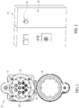
- FIG 1 illustrates an embodiment of an electrical panel adapter 10 that is fixable to a panel door of an enclosure (e.g., as shown in Figure 2 ).
- the adapter 10 includes a main unit 12, a base frame 14, and a protective cover 16 that is coupled to the base frame 14, in this instance by a hinge 18.
- the protective cover 16 is shown in an open position, whereby access to electrical sockets 20 is provided for measuring electrical parameters such as voltage and current of wires and equipment inside the enclosure.
- One example of an enclosure is an electrical box or cabinet 22, as illustrated in Figure 2 .
- the adapter 10 is shown fixed to a panel door (or other panel) 24 of the electrical box or cabinet 22, with the protective cover in a closed position.
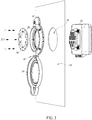
- FIG 3 is an exploded perspective side view of elements forming an embodiment of the panel adapter 10 as shown in Figures 1 and 2 .
- the main unit 12 is situated behind the panel 24.
- a front portion of the main unit 12 is sized to fit into and/or extend through an aperture 26 defined in the panel 24.
- On the opposite side of the panel 24 is a base frame 14 that, when installed, abuts against the panel 24 and provides an access port 28 that is sized to provide external access to the front portion of the main unit 12 that projects into and/or through the aperture 26.
- a fixing ring 30 is sized and configured to fit within the frame 14 and receive screws or other fasteners 32 that pass through the fixing ring 30 into the main unit 12.
- the fixing ring 30 has an outer diameter that is larger than an inside diameter of at least portions of the inside sidewall of the base frame 14. Accordingly, when the fixing ring 30 is fitted within the frame 14, the screws 32 passing through the fixing ring 30 secure the frame 14 to the main unit 12 with the panel 24 sandwiched therebetween, thus fixing the frame 14 and the main unit 12 to the panel 24.
- the frame 14 further includes a protective cover 16 that is connected to the frame 14 by a hinge 18 and, in a closed position, provides environmental protection to electrical sockets of the main unit 12 that are otherwise accessible through the access port 28 of the frame 14 when the protective cover 16 is in an open position, as shown.
- the protective cover 16 In the closed position, the protective cover 16 preferably abuts against an outer circumference of the frame 14 and seals the access port 28 and front portion of the main unit 12 from the environment outside the panel adapter 10.
- a rear surface of the frame 14 preferably seals against the panel 24 when the frame 14 is installed and secured to the main unit 12 with the panel 24 therebetween.
- the frame 14 and the main unit 12 have edge portions that abut against opposite sides of the panel 24 and form a seal around the aperture 26 in the panel 24 to protect the interior of the enclosure from the environment outside the enclosure.
- the protective cover 16 includes a transparent surface. When the protective cover is positioned in the closed position, the electrical sockets are visible through the transparent surface to the environment outside the enclosure.
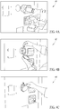
- Figures 4A-4C illustrate one example of a process for installation of at least one embodiment of the panel adapter 10.
- a first step 40 an aperture is defined in a panel door.
- a Kwik Stepper drill bit or electrohydraulic hole punch may be used to cut or otherwise define the aperture in the panel door.
- a base frame and hingedly-connected protective cover as shown in Figure 3 are fitted to the outside of the panel door around the defined aperture.
- a main unit as described in Figure 3 is positioned on the opposite side of the panel door such that a portion of the main unit extends into and/or through the aperture.
- the base frame and the main unit are thereafter secured to each other such that the base frame and main unit are fixed to opposite sides of the panel door.
- a fixing ring 30 as described in Figure 3 or a fixing plate 90 as shown in Figure 13 may be used to secure the base frame to the main unit with the panel door therebetween.
- the protective cover may be rotated about the hinge connection relative to the base frame to close the protective cover upon the base frame. In the closed position, the protective cover protects electrical sockets on a front portion of the main unit from the environment external to the panel door and the panel adapter.
- the main unit 12 may be secured to the base frame 14 in different mounting positions.
- the main unit 12 is positioned such that the electrical sockets 20 of the main unit 12 are mounted within the access port 28 of the frame 14 to provide current measurement connections on the left half of the frame and voltage measurement connections on the right half of the frame.
- the main unit 12 is rotated and mounted within the access port 28 of the frame 14 such that the current measurement connections are on the top half of the frame and the voltage measurement connections on the bottom half of the frame.
- the main unit 12 is further rotated and mounted within the access port 28 of the frame 14 such that the current measurement connections are on the bottom half of the frame and the voltage measurement connections are on the top half of the frame.
- the main unit 12 is rotated and mounted within the access port 28 of the frame 14 such that the voltage measurement connections are on the left half of the frame and the current measurement connections are on the right half of the frame.
- the main unit 12 includes electrical connection points for connecting e.g. voltage measuring lines and current measuring equipment inside an electrical enclosure to the main unit 12. Once the voltage measuring lines and current measuring equipment are connected to the main unit 12, the electrical sockets 20 on the front of the main unit 12 provide outside pass-through access to electrical signals from the voltage measuring lines and current measuring equipment inside the electrical enclosure.
- an electrician can selectively rotate and mount the main unit 12 within the access port 28 of the frame 14 as shown in Figures 5A-5D to facilitate coupling of the main unit 12 to the voltage measuring lines and current measuring equipment.
- an electrician can selectively mount the main unit 12 in different areas of a panel door and mount the main unit 12 within the frame 14 so that connection points of the main unit 12 are more easily coupled to the voltage measuring lines and current measuring equipment behind the panel door.
- the main unit 12 can likewise be rotated and mounted within the frame 14 in a different orientation if the installing electrician finds other components within the electrical enclosure blocking access to the connection points of the main unit 12.
- Figure 6 is a rear view of the main unit 12 with electrical connection points 50 for coupling measuring lines, such as voltage measuring lines, inside the enclosure to the main unit 12, as well as electrical connection points 52 for coupling measuring equipment, such as current measuring equipment, inside the enclosure to the main unit 12.
- the electrical connection points 50 and 52 are further shown in Figures 9A-9C and Figure 11 .
- the main unit 12 preferably includes appropriate labeling for the voltage connection points 50, in this instance including three lines or phases, a neutral, and an earth or ground connection, that are labeled A/L1, B/L2, C/L3, N and PE, respectively.
- Figure 7 is a side view of the main unit 12, with appropriate labeling for the current connection points 52, including in this instance five current channels, similarly for three phases, neutral, and ground, respectively labeled A/L1, B/L2, C/L3, N and PE.
- test points within an electrical enclosure for which electrical measurements, such as voltage measurements, are desired may be coupled to the connection points 50 of the main unit 12.
- Circuitry within the main unit 12 (discussed below with regard to Figures 10 and 11 ) electrically couples the connection points 50 with corresponding electrical sockets 60 on the front of the main unit 12.
- the electrical sockets 60 which are accessible through the access port 28 of the frame 14, may respectively be coupled via cabling to inputs on one or more measurement devices, such as a power quality logger 62, as shown in Figure 8A.
- Figure 8B illustrates a cable 64 with suitable connectors for electrically coupling measurement inputs, such as voltage measurement inputs, of the measurement device 62 to the electrical sockets 60.
- the electrical sockets 60 are comprised of five 4mm safety sockets that are connectable to a measurement device, such as the power quality logger 62, using standard 4mm leads as shown in Figure 8B .
- measurement devices such as current measurement devices may be arranged to measure current flowing in electrical wires or equipment for which current measurements are desired.
- the current measurement devices in the enclosure are coupled to the connection points 52 of the main unit 12.
- Circuitry within the main unit 12 electrically couples the connection points 52 with corresponding electrical sockets 66 on the front portion of the main unit 12, as illustrated in Figure 8C .
- the electrical sockets 66 which are accessible through the access port 28 of the frame 14, may respectively be coupled via cabling to one or more measurement devices, such as the power quality logger 62 shown in Figure 8C.
- Figure 8D illustrates a cable 68 with suitable connectors for electrically coupling measurement inputs, such as current measurement inputs, of the measurement device 62 in Figure 8C to the electrical sockets 66.
- the electrical sockets 66 are comprised of five ODU sockets that are connectable to a measurement device, such as the power quality logger 62, using a connection cable 68 as shown in Figure 8D .
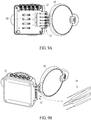
- Figures 9A and 9B further illustrate the connection points 50 for connecting measuring lines 70, which may be voltage measuring lines, to the main unit 12.
- measuring lines 70 are connected to the connection points 50 via screw terminals on the main unit 12. Exposed ends of the measuring lines 70 may be wrapped around or otherwise secured to the connection points 50, thus providing a wired galvanic connection of the connection points 50 to respective test points of electrical wiring or equipment within the enclosure where the main unit 12 is situated.
- the main unit 12 further includes a notched structure 72 that extends from a surface of the main unit 12 adjacent to the connection points 50. When the measuring lines 70 are installed and connected to the connection points 50, the measuring lines 70 may be fitted within notches of the notched structure 72. The notched structure thereby provides relief for the measuring lines 70 from strain that may occur on the lines from movement of the measuring lines, e.g. if the panel door to which the measuring unit 12 is mounted is opened at a later time.
- Figure 9C illustrates the connection points 52 for connecting measurement devices, such as current measuring devices, an example being a Rogowski coil 74, to the main unit 12.
- measurement devices such as current measuring devices, an example being a Rogowski coil 74
- cables 76 having appropriate connectors that match the sockets of the connection points 52.
- current measurement devices 74 such as standard Fluke current sensors may be coupled by respective cables 76 using known ODU connectors. Connected in this manner, the current measurement devices 74 measure current flowing through wiring of interest inside the electrical enclosure and supply the current measurements to the main unit 12.
- Circuitry in the main unit 12 electrically couples the connection points 52 to the electrical sockets 66 (see Figure 8C ) which provide external access to the current measurements by a measurement device, such as the power quality logger 62.
- the panel adapter 10 may be adapted to support instruments that can be powered by one or more of the measurement lines coupled to the panel adapter.
- Circuitry within the main unit 12 may include one or more electrical lines connected to an output socket that draw a small amount of power from the electrical lines or equipment being measured and deliver the power to a measurement device coupled to the panel adapter 10.
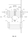
- FIG 10 provides a schematic diagram illustrating circuitry inside at least one embodiment of the main unit 12, while Figure 11 is a rear perspective cross-section view of the main unit 12 including said circuitry.
- Voltage connection points 50 labeled A/L1, B/L2, C/L3, and N are coupled to respective electrical sockets 60 via respective overcurrent protection devices 80.
- the overcurrent protection devices 80 which may comprise any standard type fuse or circuit breaker, provide overcurrent protection to measuring equipment, such as the power quality logger 62 shown in Figures 8A and 8C , that is coupled to the electrical sockets 60.
- Current measurement connection points 52 are directly electrically coupled to respective electrical sockets 66.
- Figure 12A is a pictorial front view of at least one embodiment of the main unit 12 illustrating dimensional aspects of the main unit.
- Figure 12B is a pictorial side view of at least one embodiment of the main unit 12 illustrating a dimensional aspect of the main unit
- Figure 12C is a pictorial front view of at least one embodiment of the main unit 12 illustrating additional dimensional aspects of the main unit.
- the specific dimensions may be useful when constructing and installing a main unit 12 according to the present disclosure.
- Figure 13 provides an exploded perspective view of elements forming an embodiment of the panel adapter 10.
- a main unit 12 is comprised of a housing with an electrical circuit board having electrical circuity coupled to electrical sockets and connections as earlier described.
- a base frame 14 is sized to provide external access to electrical sockets on a front portion of the main unit 12.
- a protective cover 16 is hingedly connected to the frame 14.
- a fixing plate 90 is used to secure the frame 14 to the main unit 12.
- the fixing plate 90 is sized to fit within the frame 14 and receive screws or other fasteners 92 that pass through the fixing plate 90 into the main unit 12.
- the fixing plate 90 has an outer diameter that is wider than portions of the inside sidewall of the base frame 14.
- the fixing plate 90 secures the frame 14 to the main unit 12.
- a panel door is sandwiched therebetween (e.g., as shown in Figure 3 )
- the frame 14 and the main unit 12 are fixed to the panel door.
- the panel adapter 10 including the main unit 12 may be constructed to provide some or all of the following features:
- various embodiments of the present disclosure may include an electrical panel adapter for an enclosure that is formed of at least one panel, wherein the electrical panel adapter comprises a main unit having a front portion and a rear portion.
- the rear portion includes a first plurality of electrical connections, which may be electrical terminals, adapted to connect to electrical wires and/or equipment located inside the enclosure.
- the front portion includes a second plurality of electrical connections, which may be electrical sockets, adapted to connect to one or more electrical devices located outside the enclosure for measurement of both voltage and current in the electrical wires and/or equipment.
- the second plurality of electrical connections are electrically coupled to the first plurality of electrical connections.
- the electrical panel adapter is installable on the enclosure such that the rear portion of the main unit is positioned inside the enclosure and the front portion of the main unit extends through an aperture in the at least one panel. Accordingly, the second plurality of connections are accessible from outside the enclosure for connection to electrical devices located outside the enclosure.
- the panel adapter When the electrical panel adapter is installed, the panel adapter enables electrical devices outside the enclosure to be electrically coupled to the electrical wires and/or equipment inside the enclosure via the first and second electrical connections without requiring the enclosure to be opened.
- the electrical panel adapter may further comprise an overcurrent protection device coupled between at least one first electrical connection and at least one second electrical connection when the at least one first electrical connection is configured to receive an electrical signal for measurement of voltage inside the enclosure.
- an overcurrent protection device is not necessarily coupled between a first electrical connection and a second electrical connection when the first electrical connection is configured to receive an electrical signal for measurement of current inside the enclosure.
- the electrical panel adapter may further comprise a base frame that is securable to the main unit.
- the base frame and the main unit are positioned on opposite sides of the at least one panel.
- the base frame is secured to the main unit via fasteners that extend through the at least one panel and couple to the main unit, thereby securing the electrical panel adapter to the at least one panel of the enclosure.
- the base frame may be annular and provide an access port sized to provide external access to the front portion of the main unit that extends through the aperture in the at least one panel.
- the base frame and the main unit may be sized and configured such that the fasteners extend through the aperture in the at least one panel of the enclosure.
- the base frame and the main unit may have edge portions that abut against the opposite sides of the at least one panel. The edge portions of the base frame and the main unit abut against the opposite sides of the at least one panel and form a seal around the aperture in the at least one panel to protect the interior of the enclosure from the environment outside the enclosure.
- the electrical panel adapter further comprises a protective cover coupled to the panel adapter, e.g., to the base frame of the panel adapter.
- the protective cover is positionable between a closed position and an open position. When the protective cover is in the closed position, the protective cover preferably seals against the base frame and protects the second plurality of electrical connections from the environment outside the enclosure.
- the protective cover may include a transparent surface such that, when the protective cover is positioned in the closed position, the second electrical connections of the main unit are visible through the transparent surface to the environment outside the enclosure.
- the electrical panel adapter may further comprise an annular fixing ring sized and configured to fit within the base frame and receive the fasteners that extend through the at least one panel.
- the fixing ring may have an outside diameter that is larger than an inside diameter of at least portions of the base frame. With such configuration, the fixing ring may abut against the base frame when the fasteners secure the base frame to the main unit.
- the electrical panel adapter may further comprise a fixing plate that is sized and configured to fit within the base frame and receive the fasteners that extend through the at least one panel.
- the fixing plate includes apertures that correspond to the second plurality of electrical connections and provide external access to the second plurality of electrical connections.
- the fixing plate may have having a diameter that is larger than an inside diameter of at least portions of the base frame. As with the fixing ring, with such a configuration, the fixing plate may abut against the base frame when the fasteners secure the base frame to the main unit.
- the main unit is rotatable relative to the at least one panel.
- the main unit may be rotated to a mounting position having a desired orientation that facilitates connection of the second plurality of electrical connections to electrical wires and/or equipment located inside the enclosure.
- the first plurality of electrical connections may be terminals on the rear portion of the main unit.
- the terminals are connectable via cabling to test points on the electrical wires and/or equipment located inside the enclosure for measurement of electrical parameters of the electrical wires and/or equipment.
- the electrical panel adapter may further comprise a notched structure that extends from a surface of the main unit.
- the notched structure may extend from a surface adjacent to the first plurality of electrical connections.
- the notched structure is configured to provide strain relief to the cabling that connects the first plurality of electrical connections to the electrical wires and/or equipment.
- the second plurality of electrical connections may be sockets on the front portion of the main unit.
- the sockets are connectable via cabling to one or more electrical devices located outside the enclosure for communicating electrical signals between the first plurality of electrical connections and the electrical device(s) outside the enclosure.
- At least one of the second plurality of electrical connections is configured to communicate an electrical signal for measurement of voltage inside the enclosure and at least another one of the second plurality of electrical connections is configured to communicate an electrical signal for measurement of current inside the enclosure.
- the electrical panel adapter may further comprise an output socket that supplies electrical power to devices outside the enclosure.
- circuitry within the main unit may include one or more electrical lines that are connected to the output socket to supply electrical power to the output socket.
- the circuitry draws the electrical power from an electrical wire or equipment inside the enclosure that is connected to at least one of the first electrical connections.
- various embodiments of the present disclosure include methods of installing an electrical panel adapter on an enclosure formed of at least one panel.
- the method(s) may include defining an aperture in the at least one panel of the enclosure, and fitting a main unit of the electrical panel adapter into the defined aperture, wherein the main unit has a front portion and a rear portion, the rear portion including a first plurality of electrical connections adapted to connect to electrical wires and/or equipment located inside the enclosure, and the front portion including a second plurality of electrical connections adapted to connect to one or more electrical devices located outside the enclosure, the second plurality of electrical connections being electrically coupled to the first plurality of electrical connections.
- Installation of the electrical panel adapter includes positioning the rear portion of the main unit inside the enclosure and the front portion of the main unit within the aperture defined in the at least one panel of the enclosure, such that the front portion of the main unit extends through the aperture. Accordingly, the second plurality of connections on the front portion of the main unit are accessible from outside the enclosure for connection to electrical devices outside the enclosure. In this manner, the electrical panel adapter enables electrical devices outside the enclosure to be electrically coupled to the electrical wires and/or equipment inside the enclosure via the first and second electrical connections without requiring the enclosure to be opened.
- a method of installing the electrical panel adapter may be employed with an electrical panel adapter that further has a base frame which is securable to the main unit.
- the method may further comprise positioning the base frame and the main unit on opposite sides of the at least one panel of the enclosure, and securing the base frame to the main unit via fasteners that extend through the at least one panel, thereby securing the electrical panel adapter to the at least one panel of the enclosure.
- a method of installing an electrical panel adapter may be employed with an electrical panel adapter that further has a protective cover coupled to the base frame, wherein the protective cover is positionable between a closed position and an open position.
- the method further comprises positioning the protective cover in the closed position, and sealing the protective cover against the base frame to protect the second plurality of electrical connections from the environment outside the enclosure.
- a method of installing an electrical panel adapter may be employed with an electrical panel adapter that further has an annular fixing ring that is sized and configured to fit within the base frame.
- the fixing ring has an outside diameter that is larger than an inside diameter of at least portions of the base frame and receives the fasteners that extend through the at least one panel of the enclosure.
- the method further comprises inserting the fixing ring into the base frame such that the fixing ring abuts against the base frame, and securing the base frame to the main unit by extending the fasteners through the fixing ring and the at least one panel and coupling the fasteners to the main unit.
- a method of installing an electrical panel adapter may be employed with an electrical panel adapter that has a fixing plate sized and configured to fit within the base frame.
- the fixing plate has a diameter that is larger than an inside diameter of at least portions of the base frame and receives the fasteners that extend through the at least one panel.
- the method further comprises inserting the fixing plate into the base frame such that the fixing plate abuts against the base frame, aligning apertures in the fixing plate with the second plurality of electrical connections on the front portion of the main unit, and securing the base frame to the main unit by extending the fasteners through the fixing plate and the at least one panel and coupling the fasteners to the main unit.
Landscapes
- Physics & Mathematics (AREA)
- General Physics & Mathematics (AREA)
- Engineering & Computer Science (AREA)
- Power Engineering (AREA)
- Architecture (AREA)
- Civil Engineering (AREA)
- Structural Engineering (AREA)
- Patch Boards (AREA)
- Testing Electric Properties And Detecting Electric Faults (AREA)
- Connector Housings Or Holding Contact Members (AREA)
Abstract
Description
- This disclosure pertains to enclosures containing electrical wiring and equipment behind electrical panel doors, and more particularly to providing access to electrical signals from such electrical wiring and equipment for measurement of electrical parameters.
- Current workflow for electricians to access and measure electrical wiring and equipment behind electrical panels, such as power quality testing, can be time inefficient and unsafe. Time efficiency is lost when electricians schedule downtime of the electrical equipment to obtain safe access to the wiring and equipment in the enclosure. Current workflow also exposes electricians to a dangerous environment when they open the panel door to gain access to live electrical lines and equipment.
- A typical workflow for electricians to perform measurements such as measuring power or logging power quality with a portable device requires time-consuming preparatory work to install current sensors and attach voltage test leads in the electrical enclosure. To avoid being exposed to a hazardous environment, electricians may be required to wear extensive personal protective equipment. Unreliable or even incorrect connections often result from working in such strained conditions. Scheduling downtime with the facility is a safer option but only feasible on rare occasions. What is needed is easier and safer access to live electrical wires and equipment located behind an electrical panel.
- Disclosed herein is an electrical panel adapter for installation on at least one panel of an enclosure, which may be for example a panel door of the enclosure. The electrical panel adapter is configured to feed through electrical signals for measurement of electrical parameters of wires and equipment within the enclosure and eliminate the need for electricians to wear personal protective equipment when making connections to live electrical wires and measurement devices located behind the panel door. The panel adapter provides access from outside the enclosure to a plurality of electrical wires and/or equipment behind the panel and within the enclosure for measurement of electrical parameters, including for example (but without limitation) voltage and current measurements inside the enclosure without requiring the enclosure to be opened. In at least one embodiment, access is provided for up to four voltage channels and five current channels (e.g., three phases, neutral and ground).
- In various embodiments, the panel adapter is fixed adjacent to or within an aperture defined in the panel of the enclosure. The panel adapter has terminals on its rear side that are suitable to connect to electrical wires, including rigid or stranded wires, and/or measurement equipment for receiving electrical signals (e.g., current and voltage signals) from within the enclosure. The front side of the panel adapter includes outputs in the form of sockets, such as standard 4mm safety sockets, that allow an electrician outside the enclosure to connect measuring equipment, such as a power quality logger or a digital multimeter (DMM), to the outputs of the panel adapter and make and/or receive measurements of electrical wires and equipment inside the enclosure. In addition, the panel adapter supports instruments, e.g., 173x and 174x electrical energy/power loggers provided by Fluke Corporation, that can be powered by the measurement lines coupled to the terminals on the panel adapter. In various embodiments, customer-accessible fuses in the panel adapter prevent overcurrent in the measurement connections.
- Outputs of the panel adapter provide feed-through of electrical signals from measuring equipment, such as Fluke i17XX flexible current clamps, installed on electrical wires inside the panel. For example, circular 4-pin connectors may be included to support built-in EEPROM typically found in such current measuring equipment. Sensors in the measuring equipment may be automatically detected, e.g., by Fluke 173x and 174x loggers. Adapter cables may also be used to connect electrical wires and equipment to Fluke 43X accessories and accessories without EEPROM, e.g. off-the-shelf split core transformers.
- Thus, as will be appreciated from the description herein, at least one embodiment of the disclosure provides an electrical panel adapter for an enclosure that is formed of at least one panel. The electrical panel adapter includes a main unit having a front portion and a rear portion. The rear portion of the main unit includes a first plurality of electrical connections adapted to connect to electrical wires and/or equipment located inside the enclosure, while the front portion of the main unit includes a second plurality of electrical connections adapted to connect to one or more electrical devices located outside the enclosure. The second plurality of electrical connections are electrically coupled to the first plurality of electrical connections.
- The electrical panel adapter is installable on the enclosure such that the rear portion of the main unit is positioned inside the enclosure and the front portion of the main unit extends through an aperture in the at least one panel so that the second plurality of connections are accessible from outside the enclosure for connection to electrical devices located outside the enclosure. When installed, the electrical panel adapter enables electrical devices outside the enclosure to be electrically coupled to the electrical wires and/or equipment inside the enclosure via the first and second electrical connections without requiring the enclosure to be opened.
- Installation of the panel adapter is straightforward. For at least one embodiment of the panel adapter, installation merely requires drilling a 95mm (4 inch) hole in the panel door and mounting the panel adapter adjacent to or within the hole in the panel door. For reliable protective earth connection, the panel adapter may utilize an AutoGround™ feature provided by Fluke Corporation. Electrical wires and measurement devices inside the enclosure are then coupled to the panel adapter to provide ongoing access to the electrical wires and measurement devices while the panel door remains closed.
- A method of installing an electrical panel adapter on an enclosure formed of at least one panel may thus include defining an aperture in the at least one panel of the enclosure and fitting a main unit of the electrical panel adapter into the defined aperture, wherein the main unit has a front portion and a rear portion, the rear portion including a first plurality of electrical connections adapted to connect to electrical wires and/or equipment located inside the enclosure, and the front portion including a second plurality of electrical connections adapted to connect to one or more electrical devices located outside the enclosure, and the second plurality of electrical connections being electrically coupled to the first plurality of electrical connections. When installed, the rear portion of the main unit is positioned inside the enclosure and the front portion of the main unit extends through the aperture so that the second plurality of connections are accessible from outside the enclosure for connection to electrical devices outside the enclosure. The electrical panel adapter thus enables electrical devices outside the enclosure to be electrically coupled to the electrical wires and/or equipment inside the enclosure via the first and second electrical connections without requiring the enclosure to be opened.
- Various embodiments of the panel adapter disclosed herein may thus include, by way of non-limiting example, some or all of the following concepts and features:
- (1) an electrical cabinet feed-through interface that connects measurement instruments to electrical test points, such as three-phase voltage and current test points, within the cabinet;
- (2) electrical access to electrical test points, such as three-phase test points, without having to open electrical cabinets, which avoids exposing personnel to hazardous electrical environment;
- (3) convenient routine electrical measurements can be performed without needing to shut down operating equipment and perform a lock-out tag-out process;
- (4) convenient electrical connections, such as voltage and current connections, to a measurement instrument using standard sockets;
- (5) permanent wire internal voltage connections using standard screw terminals and ODU or BNC industry-standard connections for current sensor probes;
- (6) during installation, orientation of the panel adapter can be rotated 360 degrees to allow for mounting of the panel adapter in any orientation;
- (7) simplified installation is possible using a Kwik Stepper drill bit and electrohydraulic hole punch (100 mm, 4 Inch Diameter) to define the aperture in the panel door; and
- (8) Cat III 1000V / Cat IV 600V safety rating according to IEC 61010 may be achieved, with an IP67 rating when the panel adapter is protected by a protective cover in the closed position.
- These concepts and features, as well as other concepts and features, are exemplified by various embodiments of the electrical panel adapter described herein.
-
-
Figure 1 is a front view of an embodiment of an electrical panel adapter according to the present disclosure, with a protective cover in an open position. -
Figure 2 is a perspective view of an enclosure with a panel adapter as shown inFigure 1 fixed to a panel door of the enclosure, with the protective cover in a closed position. -
Figure 3 is an exploded perspective side view of elements forming an embodiment of a panel adapter as shown inFigure 1 , in relation to a panel door with an aperture defined therein. -
Figures 4A-4C illustrate one example of a process for installation of at least one embodiment of a panel adapter according to the present disclosure. -
Figures 5A-5D illustrate a front view of a panel adapter having a main unit mounted to a base frame in different mounting orientations according to the present disclosure. -
Figure 6 is a rear view of the main unit of a panel adapter with electrical connection points for coupling electrical wires and equipment, such as voltage measuring lines and current measurement devices, to the main unit. -
Figure 7 is a side view of the main unit shown inFigure 6 . -
Figure 8A is a perspective view of a panel adapter with electrical sockets on a front portion of the main unit couplable via cabling to inputs on a rear portion of an external measurement device. -
Figure 8B is a perspective view of cabling that may be used to couple electrical sockets of the panel adapter to the external measurement device shown inFigure 8A . -
Figure 8C is a perspective view of the panel adapter shown inFigure 8A with electrical sockets on the front portion of the main unit couplable via cabling to other inputs on the rear portion of the external measurement device. -
Figure 8D is a perspective view of cabling that may be used to couple electrical sockets of the panel adapter to the external measurement device shown inFigure 8C . -
Figure 9A is a rear perspective cross-section view of the main unit of a panel adapter with connection points for coupling voltage measuring lines to the main unit. -
Figure 9B is a rear perspective view of the main unit of a panel adapter as shown inFigure 9A further illustrating a coupling of voltage measuring lines to the main unit. -
Figure 9C is a rear perspective view of the main unit of a panel adapter as shown inFigure 9A further illustrating connection points for coupling a current measuring device to the main unit. -
Figure 10 is a schematic diagram illustrating circuitry inside at least one embodiment of the main unit of a panel adapter. -
Figure 11 is a rear perspective cross-section view of the main unit of a panel adapter as shown inFigure 9A . -
Figure 12A is a pictorial front view of at least one embodiment of the main unit illustrating dimensional aspects of the main unit. -
Figure 12B is a pictorial side view of at least one embodiment of the main unit illustrating a dimensional aspect of the main unit. -
Figure 12C is a pictorial front view of at least one embodiment of the main unit illustrating dimensional aspects of the main unit. -
Figure 13 is an exploded perspective view of elements forming an embodiment of a panel adapter according to the present disclosure. - In various embodiments of the present disclosure, an electrical panel adapter can be installed on at least one panel of an electrical enclosure to give access from outside the enclosure to electrical wires and equipment inside the electrical enclosure without having to open the enclosure, e.g., for measurement of electrical parameters such as voltages and currents inside the enclosure. The panel adapter thus provides greater time efficiency for measurement of live electrical parameters inside the enclosure while also keeping servicing electricians safe outside the enclosure.
-
Figure 1 illustrates an embodiment of anelectrical panel adapter 10 that is fixable to a panel door of an enclosure (e.g., as shown inFigure 2 ). Theadapter 10 includes amain unit 12, abase frame 14, and aprotective cover 16 that is coupled to thebase frame 14, in this instance by ahinge 18. InFigure 1 , theprotective cover 16 is shown in an open position, whereby access toelectrical sockets 20 is provided for measuring electrical parameters such as voltage and current of wires and equipment inside the enclosure. One example of an enclosure is an electrical box orcabinet 22, as illustrated inFigure 2 . InFigure 2 , theadapter 10 is shown fixed to a panel door (or other panel) 24 of the electrical box orcabinet 22, with the protective cover in a closed position. -
Figure 3 is an exploded perspective side view of elements forming an embodiment of thepanel adapter 10 as shown inFigures 1 and 2 . InFigure 3 , themain unit 12 is situated behind thepanel 24. A front portion of themain unit 12 is sized to fit into and/or extend through anaperture 26 defined in thepanel 24. On the opposite side of thepanel 24 is abase frame 14 that, when installed, abuts against thepanel 24 and provides anaccess port 28 that is sized to provide external access to the front portion of themain unit 12 that projects into and/or through theaperture 26. In this embodiment of thepanel adapter 10, a fixingring 30 is sized and configured to fit within theframe 14 and receive screws orother fasteners 32 that pass through the fixingring 30 into themain unit 12. The fixingring 30 has an outer diameter that is larger than an inside diameter of at least portions of the inside sidewall of thebase frame 14. Accordingly, when the fixingring 30 is fitted within theframe 14, thescrews 32 passing through the fixingring 30 secure theframe 14 to themain unit 12 with thepanel 24 sandwiched therebetween, thus fixing theframe 14 and themain unit 12 to thepanel 24. - In the illustrated embodiment, the
frame 14 further includes aprotective cover 16 that is connected to theframe 14 by ahinge 18 and, in a closed position, provides environmental protection to electrical sockets of themain unit 12 that are otherwise accessible through theaccess port 28 of theframe 14 when theprotective cover 16 is in an open position, as shown. In the closed position, theprotective cover 16 preferably abuts against an outer circumference of theframe 14 and seals theaccess port 28 and front portion of themain unit 12 from the environment outside thepanel adapter 10. For further environmental protection, a rear surface of theframe 14 preferably seals against thepanel 24 when theframe 14 is installed and secured to themain unit 12 with thepanel 24 therebetween. In at least one embodiment, theframe 14 and themain unit 12 have edge portions that abut against opposite sides of thepanel 24 and form a seal around theaperture 26 in thepanel 24 to protect the interior of the enclosure from the environment outside the enclosure. - In at least some embodiments, the
protective cover 16 includes a transparent surface. When the protective cover is positioned in the closed position, the electrical sockets are visible through the transparent surface to the environment outside the enclosure. -
Figures 4A-4C illustrate one example of a process for installation of at least one embodiment of thepanel adapter 10. In afirst step 40, an aperture is defined in a panel door. For example, a Kwik Stepper drill bit or electrohydraulic hole punch may be used to cut or otherwise define the aperture in the panel door. - In a
second step 42, a base frame and hingedly-connected protective cover as shown inFigure 3 are fitted to the outside of the panel door around the defined aperture. At the same time, a main unit as described inFigure 3 is positioned on the opposite side of the panel door such that a portion of the main unit extends into and/or through the aperture. The base frame and the main unit are thereafter secured to each other such that the base frame and main unit are fixed to opposite sides of the panel door. For example, a fixingring 30 as described inFigure 3 or a fixing plate 90 as shown inFigure 13 may be used to secure the base frame to the main unit with the panel door therebetween. - With the main unit and the base frame thus secured to each other on opposite sides of the panel door, in a
third step 44 the protective cover may be rotated about the hinge connection relative to the base frame to close the protective cover upon the base frame. In the closed position, the protective cover protects electrical sockets on a front portion of the main unit from the environment external to the panel door and the panel adapter. - Referring now to
Figures 5A-5D , in various embodiments, themain unit 12 may be secured to thebase frame 14 in different mounting positions. InFigure 5A for example, themain unit 12 is positioned such that theelectrical sockets 20 of themain unit 12 are mounted within theaccess port 28 of theframe 14 to provide current measurement connections on the left half of the frame and voltage measurement connections on the right half of the frame. InFigure 5B for example, themain unit 12 is rotated and mounted within theaccess port 28 of theframe 14 such that the current measurement connections are on the top half of the frame and the voltage measurement connections on the bottom half of the frame. InFigure 5C for example, themain unit 12 is further rotated and mounted within theaccess port 28 of theframe 14 such that the current measurement connections are on the bottom half of the frame and the voltage measurement connections are on the top half of the frame. Lastly, inFigure 5D for example, themain unit 12 is rotated and mounted within theaccess port 28 of theframe 14 such that the voltage measurement connections are on the left half of the frame and the current measurement connections are on the right half of the frame. - In this manner, allowing the
main unit 12 to rotate, e.g., up to 360 degrees, with respect to thepanel 24 provides greater flexibility when connecting themain unit 12 to electrical wires and equipment inside the electrical enclosure. As can be seen inFigure 3 and further detailed inFigures 9A-9C , themain unit 12 includes electrical connection points for connecting e.g. voltage measuring lines and current measuring equipment inside an electrical enclosure to themain unit 12. Once the voltage measuring lines and current measuring equipment are connected to themain unit 12, theelectrical sockets 20 on the front of themain unit 12 provide outside pass-through access to electrical signals from the voltage measuring lines and current measuring equipment inside the electrical enclosure. Depending on the relative position of the voltage measuring lines and current measuring equipment inside the electrical enclosure, an electrician can selectively rotate and mount themain unit 12 within theaccess port 28 of theframe 14 as shown inFigures 5A-5D to facilitate coupling of themain unit 12 to the voltage measuring lines and current measuring equipment. For example, when installing the panel adapter, an electrician can selectively mount themain unit 12 in different areas of a panel door and mount themain unit 12 within theframe 14 so that connection points of themain unit 12 are more easily coupled to the voltage measuring lines and current measuring equipment behind the panel door. Themain unit 12 can likewise be rotated and mounted within theframe 14 in a different orientation if the installing electrician finds other components within the electrical enclosure blocking access to the connection points of themain unit 12. -
Figure 6 is a rear view of themain unit 12 with electrical connection points 50 for coupling measuring lines, such as voltage measuring lines, inside the enclosure to themain unit 12, as well as electrical connection points 52 for coupling measuring equipment, such as current measuring equipment, inside the enclosure to themain unit 12. The electrical connection points 50 and 52 are further shown inFigures 9A-9C andFigure 11 . As can be seen inFigure 6 , themain unit 12 preferably includes appropriate labeling for the voltage connection points 50, in this instance including three lines or phases, a neutral, and an earth or ground connection, that are labeled A/L1, B/L2, C/L3, N and PE, respectively.Figure 7 is a side view of themain unit 12, with appropriate labeling for the current connection points 52, including in this instance five current channels, similarly for three phases, neutral, and ground, respectively labeled A/L1, B/L2, C/L3, N and PE. - The
electrical sockets 20 on the front portion of themain unit 12, as depicted inFigure 1 , are further illustrated and discussed in reference toFigures 8A-8D . As noted earlier, test points within an electrical enclosure for which electrical measurements, such as voltage measurements, are desired may be coupled to the connection points 50 of themain unit 12. Circuitry within the main unit 12 (discussed below with regard toFigures 10 and11 ) electrically couples the connection points 50 with correspondingelectrical sockets 60 on the front of themain unit 12. Theelectrical sockets 60, which are accessible through theaccess port 28 of theframe 14, may respectively be coupled via cabling to inputs on one or more measurement devices, such as apower quality logger 62, as shown inFigure 8A. Figure 8B illustrates acable 64 with suitable connectors for electrically coupling measurement inputs, such as voltage measurement inputs, of themeasurement device 62 to theelectrical sockets 60. For example, in at least one embodiment, theelectrical sockets 60 are comprised of five 4mm safety sockets that are connectable to a measurement device, such as thepower quality logger 62, using standard 4mm leads as shown inFigure 8B . - Also, as noted earlier, within the electrical enclosure, measurement devices such as current measurement devices may be arranged to measure current flowing in electrical wires or equipment for which current measurements are desired. The current measurement devices in the enclosure are coupled to the connection points 52 of the
main unit 12. Circuitry within themain unit 12 electrically couples the connection points 52 with correspondingelectrical sockets 66 on the front portion of themain unit 12, as illustrated inFigure 8C . Theelectrical sockets 66, which are accessible through theaccess port 28 of theframe 14, may respectively be coupled via cabling to one or more measurement devices, such as thepower quality logger 62 shown inFigure 8C. Figure 8D illustrates acable 68 with suitable connectors for electrically coupling measurement inputs, such as current measurement inputs, of themeasurement device 62 inFigure 8C to theelectrical sockets 66. For example, in at least one embodiment, theelectrical sockets 66 are comprised of five ODU sockets that are connectable to a measurement device, such as thepower quality logger 62, using aconnection cable 68 as shown inFigure 8D . -
Figures 9A and 9B further illustrate the connection points 50 for connecting measuringlines 70, which may be voltage measuring lines, to themain unit 12. For at least one embodiment of thepanel adapter 10, during installation of thepanel adapter 10, the measuringlines 70 are connected to the connection points 50 via screw terminals on themain unit 12. Exposed ends of the measuringlines 70 may be wrapped around or otherwise secured to the connection points 50, thus providing a wired galvanic connection of the connection points 50 to respective test points of electrical wiring or equipment within the enclosure where themain unit 12 is situated. As illustrated, themain unit 12 further includes a notchedstructure 72 that extends from a surface of themain unit 12 adjacent to the connection points 50. When the measuringlines 70 are installed and connected to the connection points 50, the measuringlines 70 may be fitted within notches of the notchedstructure 72. The notched structure thereby provides relief for the measuringlines 70 from strain that may occur on the lines from movement of the measuring lines, e.g. if the panel door to which the measuringunit 12 is mounted is opened at a later time. -
Figure 9C illustrates the connection points 52 for connecting measurement devices, such as current measuring devices, an example being aRogowski coil 74, to themain unit 12. For at least one embodiment of thepanel adapter 10, during installation of theadapter 10,current measurement devices 74 are electrically connected to the connection points 52 viacables 76 having appropriate connectors that match the sockets of the connection points 52. For example,current measurement devices 74 such as standard Fluke current sensors may be coupled byrespective cables 76 using known ODU connectors. Connected in this manner, thecurrent measurement devices 74 measure current flowing through wiring of interest inside the electrical enclosure and supply the current measurements to themain unit 12. Circuitry in themain unit 12 electrically couples the connection points 52 to the electrical sockets 66 (seeFigure 8C ) which provide external access to the current measurements by a measurement device, such as thepower quality logger 62. - It is noted that the
panel adapter 10 may be adapted to support instruments that can be powered by one or more of the measurement lines coupled to the panel adapter. Circuitry within themain unit 12 may include one or more electrical lines connected to an output socket that draw a small amount of power from the electrical lines or equipment being measured and deliver the power to a measurement device coupled to thepanel adapter 10. -
Figure 10 provides a schematic diagram illustrating circuitry inside at least one embodiment of themain unit 12, whileFigure 11 is a rear perspective cross-section view of themain unit 12 including said circuitry. Voltage connection points 50 labeled A/L1, B/L2, C/L3, and N, are coupled to respectiveelectrical sockets 60 via respectiveovercurrent protection devices 80. Theovercurrent protection devices 80, which may comprise any standard type fuse or circuit breaker, provide overcurrent protection to measuring equipment, such as thepower quality logger 62 shown inFigures 8A and8C , that is coupled to theelectrical sockets 60. Current measurement connection points 52 are directly electrically coupled to respectiveelectrical sockets 66. Since current measurement devices, such as theRogowski coil 74 shown inFigure 9C , are not galvanically connected to electrical wires or equipment but instead sense current by way of electromagnetic fields using current transformer techniques, overcurrent protection between the connection points 52 and theelectrical sockets 66 is not needed. -
Figure 12A is a pictorial front view of at least one embodiment of themain unit 12 illustrating dimensional aspects of the main unit.Figure 12B is a pictorial side view of at least one embodiment of themain unit 12 illustrating a dimensional aspect of the main unit, whileFigure 12C is a pictorial front view of at least one embodiment of themain unit 12 illustrating additional dimensional aspects of the main unit. In these particular embodiments, the specific dimensions may be useful when constructing and installing amain unit 12 according to the present disclosure. - Lastly,
Figure 13 provides an exploded perspective view of elements forming an embodiment of thepanel adapter 10. InFigure 13 , amain unit 12 is comprised of a housing with an electrical circuit board having electrical circuity coupled to electrical sockets and connections as earlier described. Abase frame 14 is sized to provide external access to electrical sockets on a front portion of themain unit 12. Aprotective cover 16 is hingedly connected to theframe 14. In contrast toFigure 3 however, a fixing plate 90 is used to secure theframe 14 to themain unit 12. The fixing plate 90 is sized to fit within theframe 14 and receive screws orother fasteners 92 that pass through the fixing plate 90 into themain unit 12. The fixing plate 90 has an outer diameter that is wider than portions of the inside sidewall of thebase frame 14. Accordingly, when the fixing plate 90 is fitted within theframe 14 and screws 92 are driven through the fixing plate 90 into the front portion of themain unit 12, the fixing plate 90 secures theframe 14 to themain unit 12. When a panel door is sandwiched therebetween (e.g., as shown inFigure 3 ), theframe 14 and themain unit 12 are fixed to the panel door. - As can be seen in the foregoing description, in various embodiments, the
panel adapter 10 including themain unit 12 may be constructed to provide some or all of the following features: - (1) Measurement instrument voltage measuring connections are provided via standard 4 mm safety sockets;
- (2) Measurement instrument current measuring connections are provided via 4 pin ODU sockets or BNC adapters;
- (3) Internal cabinet voltage connections are wired to the main unit via standard screw terminals;
- (4) Voltage connections are safety protected using inline fuses to protect against overcurrent conditions;
- (5) Internal cabinet current test points are connected to standard current sensors via 4 pin ODU connectors or BNC adapters;
- (6) Current connection sockets facilitate using standard off-the-shelf current sensors inside the cabinet;
- (7) Installation orientation of the main unit can be rotated 360 degrees to allow for mounting the panel adapter in different areas of the cabinet, such as any of the four corners of the cabinet panel door, thus facilitating connection of the main unit to electrical wires or measurement instruments inside the cabinet;
- (8) Simplified installation is achieved using a Kwik Stepper drill bit or electrohydraulic hole punch to define an aperture in the panel door for mounting the panel adapter; and
- (9)
Cat III 1000V / Cat IV 600V safety rating is provided according to IEC 61010, with an IP67 rating when a protective cover is installed and placed in the closed position. - In view of the foregoing description, it is readily appreciated that various embodiments of the present disclosure may include an electrical panel adapter for an enclosure that is formed of at least one panel, wherein the electrical panel adapter comprises a main unit having a front portion and a rear portion. The rear portion includes a first plurality of electrical connections, which may be electrical terminals, adapted to connect to electrical wires and/or equipment located inside the enclosure. The front portion includes a second plurality of electrical connections, which may be electrical sockets, adapted to connect to one or more electrical devices located outside the enclosure for measurement of both voltage and current in the electrical wires and/or equipment. As described above, the second plurality of electrical connections are electrically coupled to the first plurality of electrical connections.
- The electrical panel adapter is installable on the enclosure such that the rear portion of the main unit is positioned inside the enclosure and the front portion of the main unit extends through an aperture in the at least one panel. Accordingly, the second plurality of connections are accessible from outside the enclosure for connection to electrical devices located outside the enclosure. When the electrical panel adapter is installed, the panel adapter enables electrical devices outside the enclosure to be electrically coupled to the electrical wires and/or equipment inside the enclosure via the first and second electrical connections without requiring the enclosure to be opened.
- In various embodiments, the electrical panel adapter may further comprise an overcurrent protection device coupled between at least one first electrical connection and at least one second electrical connection when the at least one first electrical connection is configured to receive an electrical signal for measurement of voltage inside the enclosure. Conversely, an overcurrent protection device is not necessarily coupled between a first electrical connection and a second electrical connection when the first electrical connection is configured to receive an electrical signal for measurement of current inside the enclosure.
- In various embodiments, the electrical panel adapter may further comprise a base frame that is securable to the main unit. When the electrical panel adapter is installed on the enclosure, the base frame and the main unit are positioned on opposite sides of the at least one panel. The base frame is secured to the main unit via fasteners that extend through the at least one panel and couple to the main unit, thereby securing the electrical panel adapter to the at least one panel of the enclosure. The base frame may be annular and provide an access port sized to provide external access to the front portion of the main unit that extends through the aperture in the at least one panel.
- In various embodiments, the base frame and the main unit may be sized and configured such that the fasteners extend through the aperture in the at least one panel of the enclosure. Furthermore, the base frame and the main unit may have edge portions that abut against the opposite sides of the at least one panel. The edge portions of the base frame and the main unit abut against the opposite sides of the at least one panel and form a seal around the aperture in the at least one panel to protect the interior of the enclosure from the environment outside the enclosure.
- In various embodiments, the electrical panel adapter further comprises a protective cover coupled to the panel adapter, e.g., to the base frame of the panel adapter. The protective cover is positionable between a closed position and an open position. When the protective cover is in the closed position, the protective cover preferably seals against the base frame and protects the second plurality of electrical connections from the environment outside the enclosure. The protective cover may include a transparent surface such that, when the protective cover is positioned in the closed position, the second electrical connections of the main unit are visible through the transparent surface to the environment outside the enclosure.
- In various embodiments, the electrical panel adapter may further comprise an annular fixing ring sized and configured to fit within the base frame and receive the fasteners that extend through the at least one panel. The fixing ring may have an outside diameter that is larger than an inside diameter of at least portions of the base frame. With such configuration, the fixing ring may abut against the base frame when the fasteners secure the base frame to the main unit.
- Alternatively, in various embodiments, the electrical panel adapter may further comprise a fixing plate that is sized and configured to fit within the base frame and receive the fasteners that extend through the at least one panel. The fixing plate includes apertures that correspond to the second plurality of electrical connections and provide external access to the second plurality of electrical connections. The fixing plate may have having a diameter that is larger than an inside diameter of at least portions of the base frame. As with the fixing ring, with such a configuration, the fixing plate may abut against the base frame when the fasteners secure the base frame to the main unit.
- In various embodiments, the main unit is rotatable relative to the at least one panel. Thus, the main unit may be rotated to a mounting position having a desired orientation that facilitates connection of the second plurality of electrical connections to electrical wires and/or equipment located inside the enclosure.
- As mentioned earlier, the first plurality of electrical connections may be terminals on the rear portion of the main unit. In such embodiments, the terminals are connectable via cabling to test points on the electrical wires and/or equipment located inside the enclosure for measurement of electrical parameters of the electrical wires and/or equipment.
- In various embodiments, the electrical panel adapter may further comprise a notched structure that extends from a surface of the main unit. The notched structure may extend from a surface adjacent to the first plurality of electrical connections. Preferably, the notched structure is configured to provide strain relief to the cabling that connects the first plurality of electrical connections to the electrical wires and/or equipment.
- Also as mentioned earlier, the second plurality of electrical connections may be sockets on the front portion of the main unit. In such embodiments, the sockets are connectable via cabling to one or more electrical devices located outside the enclosure for communicating electrical signals between the first plurality of electrical connections and the electrical device(s) outside the enclosure. At least one of the second plurality of electrical connections is configured to communicate an electrical signal for measurement of voltage inside the enclosure and at least another one of the second plurality of electrical connections is configured to communicate an electrical signal for measurement of current inside the enclosure.
- In various embodiments, the electrical panel adapter may further comprise an output socket that supplies electrical power to devices outside the enclosure. In such embodiments, circuitry within the main unit may include one or more electrical lines that are connected to the output socket to supply electrical power to the output socket. Preferably, the circuitry draws the electrical power from an electrical wire or equipment inside the enclosure that is connected to at least one of the first electrical connections.
- In view of the above description, it is also readily appreciated that various embodiments of the present disclosure include methods of installing an electrical panel adapter on an enclosure formed of at least one panel. In various embodiments, the method(s) may include defining an aperture in the at least one panel of the enclosure, and fitting a main unit of the electrical panel adapter into the defined aperture, wherein the main unit has a front portion and a rear portion, the rear portion including a first plurality of electrical connections adapted to connect to electrical wires and/or equipment located inside the enclosure, and the front portion including a second plurality of electrical connections adapted to connect to one or more electrical devices located outside the enclosure, the second plurality of electrical connections being electrically coupled to the first plurality of electrical connections.
- Installation of the electrical panel adapter includes positioning the rear portion of the main unit inside the enclosure and the front portion of the main unit within the aperture defined in the at least one panel of the enclosure, such that the front portion of the main unit extends through the aperture. Accordingly, the second plurality of connections on the front portion of the main unit are accessible from outside the enclosure for connection to electrical devices outside the enclosure. In this manner, the electrical panel adapter enables electrical devices outside the enclosure to be electrically coupled to the electrical wires and/or equipment inside the enclosure via the first and second electrical connections without requiring the enclosure to be opened.
- In various embodiments, a method of installing the electrical panel adapter may be employed with an electrical panel adapter that further has a base frame which is securable to the main unit. In such embodiments, the method may further comprise positioning the base frame and the main unit on opposite sides of the at least one panel of the enclosure, and securing the base frame to the main unit via fasteners that extend through the at least one panel, thereby securing the electrical panel adapter to the at least one panel of the enclosure.
- In various embodiments, a method of installing an electrical panel adapter may be employed with an electrical panel adapter that further has a protective cover coupled to the base frame, wherein the protective cover is positionable between a closed position and an open position. In such embodiments, the method further comprises positioning the protective cover in the closed position, and sealing the protective cover against the base frame to protect the second plurality of electrical connections from the environment outside the enclosure.
- In various embodiments, a method of installing an electrical panel adapter may be employed with an electrical panel adapter that further has an annular fixing ring that is sized and configured to fit within the base frame. The fixing ring has an outside diameter that is larger than an inside diameter of at least portions of the base frame and receives the fasteners that extend through the at least one panel of the enclosure. In such embodiments, the method further comprises inserting the fixing ring into the base frame such that the fixing ring abuts against the base frame, and securing the base frame to the main unit by extending the fasteners through the fixing ring and the at least one panel and coupling the fasteners to the main unit.
- Alternatively, in various embodiments, a method of installing an electrical panel adapter may be employed with an electrical panel adapter that has a fixing plate sized and configured to fit within the base frame. The fixing plate has a diameter that is larger than an inside diameter of at least portions of the base frame and receives the fasteners that extend through the at least one panel. In such embodiments, the method further comprises inserting the fixing plate into the base frame such that the fixing plate abuts against the base frame, aligning apertures in the fixing plate with the second plurality of electrical connections on the front portion of the main unit, and securing the base frame to the main unit by extending the fasteners through the fixing plate and the at least one panel and coupling the fasteners to the main unit.
- It should be appreciated that the various embodiments described above can be combined to provide yet further embodiments of the
electrical panel adapter 10 and methods of installing the same. Aspects of the embodiments can be modified, and other changes can be made to the embodiments in light of the above-detailed description, without departing from the scope of the disclosure. - These and other changes can be made to the embodiments in light of the above-detailed description. In general, in the following claims, the terms used should not be construed to limit the claims to the specific embodiments disclosed in the specification and the claims, but should be construed to include all possible embodiments along with the full scope of equivalents to which such claims are entitled. Accordingly, the claims are not limited by the disclosure.
Claims (15)
- An electrical panel adapter for an enclosure that is formed of at least one panel, the electrical panel adapter comprising:a main unit having a front portion and a rear portion, wherein the rear portion includes a first plurality of electrical connections adapted to connect to electrical wires and/or equipment located inside the enclosure, and the front portion includes a second plurality of electrical connections adapted to connect to one or more electrical devices located outside the enclosure for measurement of both voltage and current inside the enclosure, the second plurality of electrical connections being electrically coupled to the first plurality of electrical connections;wherein the electrical panel adapter is installable on the enclosure such that the rear portion of the main unit is positioned inside the enclosure and the front portion of the main unit extends through an aperture in the at least one panel so that the second plurality of connections are accessible from outside the enclosure for connection to electrical devices located outside the enclosure, and when installed, the electrical panel adapter enables electrical devices outside the enclosure to be electrically coupled to the electrical wires and/or equipment inside the enclosure via the first and second electrical connections without requiring the enclosure to be opened.
- The electrical panel adapter of claim 1, further comprising a base frame that is securable to the main unit, wherein when the electrical panel adapter is installed on the enclosure, the base frame and the main unit are positioned on opposite sides of the at least one panel, and wherein the base frame is secured to the main unit via fasteners that extend through the at least one panel and couple to the main unit, thereby securing the electrical panel adapter to the at least one panel of the enclosure.
- The electrical panel adapter of claim 2, wherein the base frame and the main unit are sized and configured such that the fasteners extend through the aperture in the at least one panel, and the base frame and the main unit have edge portions that abut against the opposite sides of the at least one panel;
wherein preferably the edge portions of the base frame and the main unit that abut against the opposite sides of the at least one panel form a seal around the aperture in the at least one panel to protect the interior of the enclosure from the environment outside the enclosure. - The electrical panel adapter of claim 2 or 3, further comprising a protective cover coupled to the base frame, wherein the protective cover is positionable between a closed position and an open position, and when the protective cover is in the closed position, the protective cover seals against the base frame and protects the second plurality of electrical connections from the environment outside the enclosure.
- The electrical panel adapter of claim 4, wherein the protective cover includes a transparent surface such that, when the protective cover is positioned in the closed position, the second electrical connections are visible through the transparent surface to the environment outside the enclosure.
- The electrical panel adapter of any of claims 2 to 5, wherein the base frame is annular and provides an access port sized to provide external access to the front portion of the main unit that extends through the aperture in the at least one panel.
- The electrical panel adapter of claim 6, further comprising an annular fixing ring sized and configured to fit within the base frame and receive the fasteners that extend through the at least one panel, wherein the fixing ring has an outside diameter that is larger than an inside diameter of at least portions of the base frame, the fixing ring abutting against the base frame when the fasteners secure the base frame to the main unit; and/or
a fixing plate sized and configured to fit within the base frame and receive the fasteners that extend through the at least one panel, wherein the fixing plate includes apertures that correspond to the second plurality of electrical connections and provide external access to the second plurality of electrical connections, the fixing plate further having a diameter that is larger than an inside diameter of at least portions of the base frame, and the fixing plate abutting against the base frame when the fasteners secure the base frame to the main unit. - The electrical panel adapter of any of claims 1 to 7, wherein the main unit is rotatable relative to the at least one panel to a mounting position having a desired orientation that facilitates connection of the second plurality of electrical connections to electrical wires and/or equipment located inside the enclosure; and/or
wherein the first plurality of electrical connections are terminals that are connectable via cabling to test points inside the enclosure for measurement of electrical parameters including both voltage and current inside the enclosure. - The electrical panel adapter of claim 8, further comprising a notched structure that extends from a surface of the main unit adjacent to the first plurality of electrical connections, wherein the notched structure is configured to provide strain relief to the cabling that connects the first plurality of electrical connections to the electrical wires and/or equipment.
- The electrical panel adapter of any of claims 1 to 9, wherein the second plurality of electrical connections are sockets that are connectable via cabling to one or more electrical devices located outside the enclosure for communicating electrical signals between the first plurality of electrical connections and the one or more electrical devices outside the enclosure, wherein at least one of the second plurality of electrical connections is configured to communicate an electrical signal for measurement of voltage inside the enclosure and at least another one of the second plurality of electrical connections is configured to communicate an electrical signal for measurement of current inside the enclosure.
- The electrical panel adapter of any of claims 1 to 10, further comprising an overcurrent protection device coupled between at least one first electrical connection and at least one second electrical connection when the at least one first electrical connection is configured to receive an electrical signal for measurement of voltage inside the enclosure, while an overcurrent protection device is not coupled between a first electrical connection and a second electrical connection when said first electrical connection is configured to receive an electrical signal for measurement of current inside the enclosure; and/or
an output socket and circuitry within the main unit that includes one or more electrical lines connected to the output socket to supply electrical power to the output socket, wherein the electrical power is drawn from an electrical wire or equipment inside the enclosure that is connected to at least one of the first electrical connections. - A method of installing an electrical panel adapter on an enclosure formed of at least one panel, the method comprising:defining an aperture in the at least one panel of the enclosure;fitting a main unit of the electrical panel adapter into the defined aperture, wherein the main unit has a front portion and a rear portion, the rear portion including a first plurality of electrical connections adapted to connect to electrical wires and/or equipment located inside the enclosure, and the front portion including a second plurality of electrical connections adapted to connect to one or more electrical devices located outside the enclosure, the second plurality of electrical connections being electrically coupled to the first plurality of electrical connections,wherein when installed, the rear portion of the main unit is positioned inside the enclosure and the front portion of the main unit extends through the aperture so that the second plurality of connections are accessible from outside the enclosure for connection to electrical devices outside the enclosure, and the electrical panel adapter enables electrical devices outside the enclosure to be electrically coupled to the electrical wires and/or equipment inside the enclosure via the first and second electrical connections without requiring the enclosure to be opened.
- The method of installing an electrical panel adapter according to claim 12, wherein the electrical panel adapter further has a base frame that is securable to the main unit, the method further comprising:positioning the base frame and the main unit on opposite sides of the at least one panel of the enclosure, andsecuring the base frame to the main unit via fasteners that extend through the at least one panel, thereby securing the electrical panel adapter to the at least one panel of the enclosure.
- The method of installing an electrical panel adapter according to claim 13, wherein the electrical panel adapter further has a protective cover coupled to the base frame, and the protective cover is positionable between a closed position and an open position, the method further comprising:positioning the protective cover in the closed position; andsealing the protective cover against the base frame to protect the second plurality of electrical connections from the environment outside the enclosure.
- The method of installing an electrical panel adapter according to claim 13 or 14, wherein the electrical panel adapter further has an annular fixing ring sized and configured to fit within the base frame and receive the fasteners that extend through the at least one panel, the fixing ring having an outside diameter that is larger than an inside diameter of at least portions of the base frame, the method further comprising:inserting the fixing ring into the base frame such that the fixing ring abuts against the base frame; andsecuring the base frame to the main unit by extending the fasteners through the fixing ring and the at least one panel and coupling the fasteners to the main unit; and/orwherein the electrical panel adapter further has a fixing plate sized and configured to fit within the base frame and receive the fasteners that extend through the at least one panel, the fixing plate having a diameter that is larger than an inside diameter of at least portions of the base frame, the method further comprising:inserting the fixing plate into the base frame such that the fixing plate abuts against the base frame;aligning apertures in the fixing plate with the second plurality of electrical connections on the front portion of the main unit; andsecuring the base frame to the main unit by extending the fasteners through the fixing plate and the at least one panel and coupling the fasteners to the main unit.
Applications Claiming Priority (1)
| Application Number | Priority Date | Filing Date | Title |
|---|---|---|---|
| US201862685836P | 2018-06-15 | 2018-06-15 |
Publications (2)
| Publication Number | Publication Date |
|---|---|
| EP3582344A1 true EP3582344A1 (en) | 2019-12-18 |
| EP3582344B1 EP3582344B1 (en) | 2023-08-02 |
Family
ID=66857842
Family Applications (1)
| Application Number | Title | Priority Date | Filing Date |
|---|---|---|---|
| EP19180091.1A Active EP3582344B1 (en) | 2018-06-15 | 2019-06-13 | Electrical panel adapter providing pass through access to electrical signals within an enclosure |
Country Status (4)
| Country | Link |
|---|---|
| US (1) | US11552460B2 (en) |
| EP (1) | EP3582344B1 (en) |
| JP (1) | JP7421873B2 (en) |
| CN (1) | CN110609151B (en) |
Cited By (1)
| Publication number | Priority date | Publication date | Assignee | Title |
|---|---|---|---|---|
| EP3704775A1 (en) * | 2017-11-02 | 2020-09-09 | Panduit Corp. | Access ports for electrical enclosures |
Families Citing this family (6)
| Publication number | Priority date | Publication date | Assignee | Title |
|---|---|---|---|---|
| USD915291S1 (en) * | 2018-06-15 | 2021-04-06 | Fluke Corporation | Panel adapter for voltage and current measurement |
| CN110581395B (en) * | 2019-08-23 | 2024-08-06 | 赛尔富电子有限公司 | Embedded electricity taking plug, electricity taking bracket and goods shelf electricity taking system |
| JP7549966B2 (en) | 2020-03-03 | 2024-09-12 | 日本製鋼所M&E株式会社 | Wind turbine generator control unit, wind turbine generator, wind turbine generator control method and control program |
| US11092655B1 (en) * | 2020-04-01 | 2021-08-17 | Gulfstream Aerospace Corporation | Apparatus and method for testing electrical wiring of a device |
| CN114578216B (en) * | 2022-04-30 | 2022-07-15 | 南昌耀德精密五金有限公司 | A conductive device for chip testing |
| USD1080524S1 (en) * | 2022-09-08 | 2025-06-24 | Volta Charging, Llc | Charging station |
Citations (3)
| Publication number | Priority date | Publication date | Assignee | Title |
|---|---|---|---|---|
| GB2465831A (en) * | 2008-12-04 | 2010-06-09 | Paul James Leverton | Electrical installation with external test point |
| US9234914B2 (en) * | 2013-03-15 | 2016-01-12 | Rockwell Automation Technologies Incorporated | Apparatus to verify an electrically safe work condition |
| US20170292975A1 (en) * | 2016-04-08 | 2017-10-12 | Abb Schweiz Ag | Test block with faraday cage |
Family Cites Families (26)
| Publication number | Priority date | Publication date | Assignee | Title |
|---|---|---|---|---|
| JPS6121810Y2 (en) * | 1980-10-18 | 1986-06-30 | ||
| US4729064A (en) * | 1985-03-04 | 1988-03-01 | Adc Telecommunications, Inc. | Modular interconnect block with protector structure |
| US5302140A (en) * | 1993-04-02 | 1994-04-12 | At&T Bell Laboratories | Connector with mounting collar for use in universal patch panel systems |
| CA2261307A1 (en) | 1997-05-22 | 1998-11-26 | Mark R. Drane | Cable splice closure |
| US6677742B1 (en) * | 1999-09-24 | 2004-01-13 | Landis+Gyr Inc. | Utility meter having a security sealing arrangement |
| JP2001345142A (en) * | 2000-05-31 | 2001-12-14 | Pfu Ltd | Connector display panel |
| JP4089151B2 (en) | 2000-11-10 | 2008-05-28 | 住友電装株式会社 | Connector panel mounting structure |
| US6784385B2 (en) * | 2002-04-29 | 2004-08-31 | Hernandez-Perez Ruben | Electrical transfer switch |
| JP4096836B2 (en) | 2003-08-08 | 2008-06-04 | 松下電工株式会社 | Automotive outlet |
| FR2878379B1 (en) * | 2004-11-19 | 2008-04-04 | Airbus France Sas | ELECTRICAL CABINET WITH ELECTRICAL CONNECTION AT ITS DOOR |
| JP4379417B2 (en) | 2005-05-16 | 2009-12-09 | パナソニック電工株式会社 | Speaker terminal |
| JP2007086876A (en) | 2005-09-20 | 2007-04-05 | Ricoh Co Ltd | Ac adapter loaded with data transmission path |
| JP4882698B2 (en) | 2006-11-17 | 2012-02-22 | 東京電力株式会社 | Test plug |
| JP2009026662A (en) * | 2007-07-20 | 2009-02-05 | Chugoku Electric Power Co Inc:The | Higuchi clip and measuring device |
| JP2009041952A (en) | 2007-08-06 | 2009-02-26 | Chugoku Electric Power Co Inc:The | Measuring device |
| US7862352B2 (en) * | 2008-08-22 | 2011-01-04 | Cooper Technologies Company | Stackable electrical panel modules |
| JP5270426B2 (en) | 2009-03-31 | 2013-08-21 | 株式会社野村総合研究所 | Wiring tracking device, power supply communication adapter, and signal notification communication adapter |
| JP2012190876A (en) * | 2011-03-09 | 2012-10-04 | Yaskawa Electric Corp | Control board |
| US8913354B2 (en) * | 2012-04-19 | 2014-12-16 | Eaton Corporation | Enclosed metering and protective electrical apparatus including an external disconnect handle |
| CN203133118U (en) * | 2013-01-04 | 2013-08-14 | 航天科工防御技术研究试验中心 | Adapter for electric connector test |
| US20150015234A1 (en) | 2013-07-11 | 2015-01-15 | Cintas Corporation | Contact voltage detection system and method |
| CN204666658U (en) * | 2014-12-31 | 2015-09-23 | 中国运载火箭技术研究院 | Dc/dc power supply voltage converter test adapter |
| US9500672B1 (en) * | 2015-04-30 | 2016-11-22 | Solarcity Corporation | Meter socket adaptor |
| CN107153128A (en) * | 2017-05-22 | 2017-09-12 | 中国电子科技集团公司第四十研究所 | A kind of slip interface device for interface adapter receiving terminal |
| CN109473973A (en) * | 2017-09-08 | 2019-03-15 | 太阳能安吉科技有限公司 | Electrical service adapter for supply side interconnection |
| US11300424B2 (en) * | 2018-12-12 | 2022-04-12 | Electro Industries/Gaugetech | Metering assembly, switchboard case, adapter cradle and method of use |
-
2019
- 2019-06-13 EP EP19180091.1A patent/EP3582344B1/en active Active
- 2019-06-14 JP JP2019111052A patent/JP7421873B2/en active Active
- 2019-06-14 CN CN201910515779.3A patent/CN110609151B/en active Active
- 2019-06-17 US US16/443,572 patent/US11552460B2/en active Active
Patent Citations (3)
| Publication number | Priority date | Publication date | Assignee | Title |
|---|---|---|---|---|
| GB2465831A (en) * | 2008-12-04 | 2010-06-09 | Paul James Leverton | Electrical installation with external test point |
| US9234914B2 (en) * | 2013-03-15 | 2016-01-12 | Rockwell Automation Technologies Incorporated | Apparatus to verify an electrically safe work condition |
| US20170292975A1 (en) * | 2016-04-08 | 2017-10-12 | Abb Schweiz Ag | Test block with faraday cage |
Cited By (1)
| Publication number | Priority date | Publication date | Assignee | Title |
|---|---|---|---|---|
| EP3704775A1 (en) * | 2017-11-02 | 2020-09-09 | Panduit Corp. | Access ports for electrical enclosures |
Also Published As
| Publication number | Publication date |
|---|---|
| JP2020035737A (en) | 2020-03-05 |
| JP7421873B2 (en) | 2024-01-25 |
| CN110609151A (en) | 2019-12-24 |
| US11552460B2 (en) | 2023-01-10 |
| EP3582344B1 (en) | 2023-08-02 |
| CN110609151B (en) | 2024-09-20 |
| US20190386469A1 (en) | 2019-12-19 |
Similar Documents
| Publication | Publication Date | Title |
|---|---|---|
| US11552460B2 (en) | Electrical panel adapter providing pass through access to electrical signals within an enclosure | |
| US8193803B2 (en) | Current measuring device | |
| EP2587500B1 (en) | Transformer instrumentation and metering system | |
| US20100231198A1 (en) | Current measuring device | |
| US10048088B2 (en) | Wireless intelligent electronic device | |
| CN102047127B (en) | Faraday optical current sensor arrangement | |
| CA2452711A1 (en) | Modular sensor array, metering device and mounting and connection base | |
| CA2288831A1 (en) | Modular sensor array, metering device, mounting and connection base | |
| US6291986B1 (en) | Insert for measuring current in conductors within an electrical enclosure | |
| US6333464B1 (en) | Electric wire splice connector | |
| JP2020035737A5 (en) | ||
| US4616177A (en) | Safety measurement device junction box | |
| US2249075A (en) | Test device for detachable electrical instruments | |
| US11444444B2 (en) | Arc detection antenna in electric meter systems | |
| US8248059B2 (en) | Electronic transformer measuring device having surface mounting assembly | |
| KR200429128Y1 (en) | Airtight switchgear to check bus deterioration status | |
| CN106970290B (en) | One kind is for cable electric performance test modularization switching adaptive device | |
| US5923527A (en) | Safe electrical interconnection box and methods of safe electrical interconnection | |
| US11189421B2 (en) | Phase and zero-sequence current sensing modules mounted together on a cable bushing | |
| KR20170002884U (en) | 3 phase all-in-one type current transformer for watt-hour meter | |
| US6577115B1 (en) | Apparatus with separated conductors | |
| KR101653227B1 (en) | Connector having a Sensor module and Distributing Board using thereof | |
| JP2011180104A (en) | Clamp-type instrument stationary terminal | |
| US7046032B2 (en) | Electrical connection plug for remote monitoring of high voltage motors | |
| JP2005051909A (en) | Distribution board |
Legal Events
| Date | Code | Title | Description |
|---|---|---|---|
| PUAI | Public reference made under article 153(3) epc to a published international application that has entered the european phase |
Free format text: ORIGINAL CODE: 0009012 |
|
| STAA | Information on the status of an ep patent application or granted ep patent |
Free format text: STATUS: THE APPLICATION HAS BEEN PUBLISHED |
|
| AK | Designated contracting states |
Kind code of ref document: A1 Designated state(s): AL AT BE BG CH CY CZ DE DK EE ES FI FR GB GR HR HU IE IS IT LI LT LU LV MC MK MT NL NO PL PT RO RS SE SI SK SM TR |
|
| AX | Request for extension of the european patent |
Extension state: BA ME |
|
| STAA | Information on the status of an ep patent application or granted ep patent |
Free format text: STATUS: REQUEST FOR EXAMINATION WAS MADE |
|
| 17P | Request for examination filed |
Effective date: 20200618 |
|
| RBV | Designated contracting states (corrected) |
Designated state(s): AL AT BE BG CH CY CZ DE DK EE ES FI FR GB GR HR HU IE IS IT LI LT LU LV MC MK MT NL NO PL PT RO RS SE SI SK SM TR |
|
| STAA | Information on the status of an ep patent application or granted ep patent |
Free format text: STATUS: EXAMINATION IS IN PROGRESS |
|
| 17Q | First examination report despatched |
Effective date: 20210701 |
|
| GRAP | Despatch of communication of intention to grant a patent |
Free format text: ORIGINAL CODE: EPIDOSNIGR1 |
|
| STAA | Information on the status of an ep patent application or granted ep patent |
Free format text: STATUS: GRANT OF PATENT IS INTENDED |
|
| RIC1 | Information provided on ipc code assigned before grant |
Ipc: H01R 31/06 20060101ALN20221221BHEP Ipc: H01R 13/68 20110101ALN20221221BHEP Ipc: H01R 13/74 20060101ALN20221221BHEP Ipc: G01R 1/04 20060101ALI20221221BHEP Ipc: H02B 1/24 20060101ALI20221221BHEP Ipc: H02B 1/30 20060101ALI20221221BHEP Ipc: H02B 1/06 20060101ALI20221221BHEP Ipc: H02B 1/04 20060101AFI20221221BHEP |
|
| INTG | Intention to grant announced |
Effective date: 20230123 |
|
| RIC1 | Information provided on ipc code assigned before grant |
Ipc: H01R 31/06 20060101ALN20230113BHEP Ipc: H01R 13/68 20060101ALN20230113BHEP Ipc: H01R 13/74 20060101ALN20230113BHEP Ipc: G01R 1/04 20060101ALI20230113BHEP Ipc: H02B 1/24 20060101ALI20230113BHEP Ipc: H02B 1/30 20060101ALI20230113BHEP Ipc: H02B 1/06 20060101ALI20230113BHEP Ipc: H02B 1/04 20060101AFI20230113BHEP |
|
| GRAS | Grant fee paid |
Free format text: ORIGINAL CODE: EPIDOSNIGR3 |
|
| GRAA | (expected) grant |
Free format text: ORIGINAL CODE: 0009210 |
|
| STAA | Information on the status of an ep patent application or granted ep patent |
Free format text: STATUS: THE PATENT HAS BEEN GRANTED |
|
| AK | Designated contracting states |
Kind code of ref document: B1 Designated state(s): AL AT BE BG CH CY CZ DE DK EE ES FI FR GB GR HR HU IE IS IT LI LT LU LV MC MK MT NL NO PL PT RO RS SE SI SK SM TR |
|
| REG | Reference to a national code |
Ref country code: GB Ref legal event code: FG4D |
|
| REG | Reference to a national code |
Ref country code: CH Ref legal event code: EP |
|
| REG | Reference to a national code |
Ref country code: DE Ref legal event code: R096 Ref document number: 602019033887 Country of ref document: DE |
|
| REG | Reference to a national code |
Ref country code: IE Ref legal event code: FG4D |
|
| REG | Reference to a national code |
Ref country code: LT Ref legal event code: MG9D |
|
| REG | Reference to a national code |
Ref country code: NL Ref legal event code: MP Effective date: 20230802 |
|
| REG | Reference to a national code |
Ref country code: AT Ref legal event code: MK05 Ref document number: 1595902 Country of ref document: AT Kind code of ref document: T Effective date: 20230802 |
|
| PG25 | Lapsed in a contracting state [announced via postgrant information from national office to epo] |
Ref country code: GR Free format text: LAPSE BECAUSE OF FAILURE TO SUBMIT A TRANSLATION OF THE DESCRIPTION OR TO PAY THE FEE WITHIN THE PRESCRIBED TIME-LIMIT Effective date: 20231103 |
|
| PG25 | Lapsed in a contracting state [announced via postgrant information from national office to epo] |
Ref country code: IS Free format text: LAPSE BECAUSE OF FAILURE TO SUBMIT A TRANSLATION OF THE DESCRIPTION OR TO PAY THE FEE WITHIN THE PRESCRIBED TIME-LIMIT Effective date: 20231202 |
|
| PG25 | Lapsed in a contracting state [announced via postgrant information from national office to epo] |
Ref country code: SE Free format text: LAPSE BECAUSE OF FAILURE TO SUBMIT A TRANSLATION OF THE DESCRIPTION OR TO PAY THE FEE WITHIN THE PRESCRIBED TIME-LIMIT Effective date: 20230802 Ref country code: RS Free format text: LAPSE BECAUSE OF FAILURE TO SUBMIT A TRANSLATION OF THE DESCRIPTION OR TO PAY THE FEE WITHIN THE PRESCRIBED TIME-LIMIT Effective date: 20230802 Ref country code: PT Free format text: LAPSE BECAUSE OF FAILURE TO SUBMIT A TRANSLATION OF THE DESCRIPTION OR TO PAY THE FEE WITHIN THE PRESCRIBED TIME-LIMIT Effective date: 20231204 Ref country code: NO Free format text: LAPSE BECAUSE OF FAILURE TO SUBMIT A TRANSLATION OF THE DESCRIPTION OR TO PAY THE FEE WITHIN THE PRESCRIBED TIME-LIMIT Effective date: 20231102 Ref country code: NL Free format text: LAPSE BECAUSE OF FAILURE TO SUBMIT A TRANSLATION OF THE DESCRIPTION OR TO PAY THE FEE WITHIN THE PRESCRIBED TIME-LIMIT Effective date: 20230802 Ref country code: LV Free format text: LAPSE BECAUSE OF FAILURE TO SUBMIT A TRANSLATION OF THE DESCRIPTION OR TO PAY THE FEE WITHIN THE PRESCRIBED TIME-LIMIT Effective date: 20230802 Ref country code: LT Free format text: LAPSE BECAUSE OF FAILURE TO SUBMIT A TRANSLATION OF THE DESCRIPTION OR TO PAY THE FEE WITHIN THE PRESCRIBED TIME-LIMIT Effective date: 20230802 Ref country code: IS Free format text: LAPSE BECAUSE OF FAILURE TO SUBMIT A TRANSLATION OF THE DESCRIPTION OR TO PAY THE FEE WITHIN THE PRESCRIBED TIME-LIMIT Effective date: 20231202 Ref country code: HR Free format text: LAPSE BECAUSE OF FAILURE TO SUBMIT A TRANSLATION OF THE DESCRIPTION OR TO PAY THE FEE WITHIN THE PRESCRIBED TIME-LIMIT Effective date: 20230802 Ref country code: GR Free format text: LAPSE BECAUSE OF FAILURE TO SUBMIT A TRANSLATION OF THE DESCRIPTION OR TO PAY THE FEE WITHIN THE PRESCRIBED TIME-LIMIT Effective date: 20231103 Ref country code: FI Free format text: LAPSE BECAUSE OF FAILURE TO SUBMIT A TRANSLATION OF THE DESCRIPTION OR TO PAY THE FEE WITHIN THE PRESCRIBED TIME-LIMIT Effective date: 20230802 Ref country code: AT Free format text: LAPSE BECAUSE OF FAILURE TO SUBMIT A TRANSLATION OF THE DESCRIPTION OR TO PAY THE FEE WITHIN THE PRESCRIBED TIME-LIMIT Effective date: 20230802 |
|
| PG25 | Lapsed in a contracting state [announced via postgrant information from national office to epo] |
Ref country code: PL Free format text: LAPSE BECAUSE OF FAILURE TO SUBMIT A TRANSLATION OF THE DESCRIPTION OR TO PAY THE FEE WITHIN THE PRESCRIBED TIME-LIMIT Effective date: 20230802 |
|
| PG25 | Lapsed in a contracting state [announced via postgrant information from national office to epo] |
Ref country code: ES Free format text: LAPSE BECAUSE OF FAILURE TO SUBMIT A TRANSLATION OF THE DESCRIPTION OR TO PAY THE FEE WITHIN THE PRESCRIBED TIME-LIMIT Effective date: 20230802 |
|
| PG25 | Lapsed in a contracting state [announced via postgrant information from national office to epo] |
Ref country code: SM Free format text: LAPSE BECAUSE OF FAILURE TO SUBMIT A TRANSLATION OF THE DESCRIPTION OR TO PAY THE FEE WITHIN THE PRESCRIBED TIME-LIMIT Effective date: 20230802 Ref country code: RO Free format text: LAPSE BECAUSE OF FAILURE TO SUBMIT A TRANSLATION OF THE DESCRIPTION OR TO PAY THE FEE WITHIN THE PRESCRIBED TIME-LIMIT Effective date: 20230802 Ref country code: ES Free format text: LAPSE BECAUSE OF FAILURE TO SUBMIT A TRANSLATION OF THE DESCRIPTION OR TO PAY THE FEE WITHIN THE PRESCRIBED TIME-LIMIT Effective date: 20230802 Ref country code: EE Free format text: LAPSE BECAUSE OF FAILURE TO SUBMIT A TRANSLATION OF THE DESCRIPTION OR TO PAY THE FEE WITHIN THE PRESCRIBED TIME-LIMIT Effective date: 20230802 Ref country code: DK Free format text: LAPSE BECAUSE OF FAILURE TO SUBMIT A TRANSLATION OF THE DESCRIPTION OR TO PAY THE FEE WITHIN THE PRESCRIBED TIME-LIMIT Effective date: 20230802 Ref country code: CZ Free format text: LAPSE BECAUSE OF FAILURE TO SUBMIT A TRANSLATION OF THE DESCRIPTION OR TO PAY THE FEE WITHIN THE PRESCRIBED TIME-LIMIT Effective date: 20230802 Ref country code: SK Free format text: LAPSE BECAUSE OF FAILURE TO SUBMIT A TRANSLATION OF THE DESCRIPTION OR TO PAY THE FEE WITHIN THE PRESCRIBED TIME-LIMIT Effective date: 20230802 |
|
| REG | Reference to a national code |
Ref country code: DE Ref legal event code: R097 Ref document number: 602019033887 Country of ref document: DE |
|
| PG25 | Lapsed in a contracting state [announced via postgrant information from national office to epo] |
Ref country code: IT Free format text: LAPSE BECAUSE OF FAILURE TO SUBMIT A TRANSLATION OF THE DESCRIPTION OR TO PAY THE FEE WITHIN THE PRESCRIBED TIME-LIMIT Effective date: 20230802 |
|
| PLBE | No opposition filed within time limit |
Free format text: ORIGINAL CODE: 0009261 |
|
| STAA | Information on the status of an ep patent application or granted ep patent |
Free format text: STATUS: NO OPPOSITION FILED WITHIN TIME LIMIT |
|
| 26N | No opposition filed |
Effective date: 20240503 |
|
| PG25 | Lapsed in a contracting state [announced via postgrant information from national office to epo] |
Ref country code: SI Free format text: LAPSE BECAUSE OF FAILURE TO SUBMIT A TRANSLATION OF THE DESCRIPTION OR TO PAY THE FEE WITHIN THE PRESCRIBED TIME-LIMIT Effective date: 20230802 |
|
| PG25 | Lapsed in a contracting state [announced via postgrant information from national office to epo] |
Ref country code: BG Free format text: LAPSE BECAUSE OF FAILURE TO SUBMIT A TRANSLATION OF THE DESCRIPTION OR TO PAY THE FEE WITHIN THE PRESCRIBED TIME-LIMIT Effective date: 20230802 |
|
| PG25 | Lapsed in a contracting state [announced via postgrant information from national office to epo] |
Ref country code: BG Free format text: LAPSE BECAUSE OF FAILURE TO SUBMIT A TRANSLATION OF THE DESCRIPTION OR TO PAY THE FEE WITHIN THE PRESCRIBED TIME-LIMIT Effective date: 20230802 |
|
| PG25 | Lapsed in a contracting state [announced via postgrant information from national office to epo] |
Ref country code: MC Free format text: LAPSE BECAUSE OF FAILURE TO SUBMIT A TRANSLATION OF THE DESCRIPTION OR TO PAY THE FEE WITHIN THE PRESCRIBED TIME-LIMIT Effective date: 20230802 |
|
| REG | Reference to a national code |
Ref country code: CH Ref legal event code: PL |
|
| PG25 | Lapsed in a contracting state [announced via postgrant information from national office to epo] |
Ref country code: LU Free format text: LAPSE BECAUSE OF NON-PAYMENT OF DUE FEES Effective date: 20240613 |
|
| PG25 | Lapsed in a contracting state [announced via postgrant information from national office to epo] |
Ref country code: IE Free format text: LAPSE BECAUSE OF NON-PAYMENT OF DUE FEES Effective date: 20240613 |
|
| PG25 | Lapsed in a contracting state [announced via postgrant information from national office to epo] |
Ref country code: CH Free format text: LAPSE BECAUSE OF NON-PAYMENT OF DUE FEES Effective date: 20240630 Ref country code: BE Free format text: LAPSE BECAUSE OF NON-PAYMENT OF DUE FEES Effective date: 20240630 |
|
| REG | Reference to a national code |
Ref country code: BE Ref legal event code: MM Effective date: 20240630 |
|
| PGFP | Annual fee paid to national office [announced via postgrant information from national office to epo] |
Ref country code: DE Payment date: 20250626 Year of fee payment: 7 |
|
| PGFP | Annual fee paid to national office [announced via postgrant information from national office to epo] |
Ref country code: GB Payment date: 20250618 Year of fee payment: 7 |
|
| PGFP | Annual fee paid to national office [announced via postgrant information from national office to epo] |
Ref country code: FR Payment date: 20250624 Year of fee payment: 7 |
|
| PG25 | Lapsed in a contracting state [announced via postgrant information from national office to epo] |
Ref country code: CY Free format text: LAPSE BECAUSE OF FAILURE TO SUBMIT A TRANSLATION OF THE DESCRIPTION OR TO PAY THE FEE WITHIN THE PRESCRIBED TIME-LIMIT; INVALID AB INITIO Effective date: 20190613 |
|
| PG25 | Lapsed in a contracting state [announced via postgrant information from national office to epo] |
Ref country code: HU Free format text: LAPSE BECAUSE OF FAILURE TO SUBMIT A TRANSLATION OF THE DESCRIPTION OR TO PAY THE FEE WITHIN THE PRESCRIBED TIME-LIMIT; INVALID AB INITIO Effective date: 20190613 |