EP3582090B1 - Device for entry of data designed to be affixed to a touchpad of a terminal, corresponding input method and system - Google Patents
Device for entry of data designed to be affixed to a touchpad of a terminal, corresponding input method and system Download PDFInfo
- Publication number
- EP3582090B1 EP3582090B1 EP19179642.4A EP19179642A EP3582090B1 EP 3582090 B1 EP3582090 B1 EP 3582090B1 EP 19179642 A EP19179642 A EP 19179642A EP 3582090 B1 EP3582090 B1 EP 3582090B1
- Authority
- EP
- European Patent Office
- Prior art keywords
- network
- conductive tracks
- touch screen
- capacitance
- contact
- Prior art date
- Legal status (The legal status is an assumption and is not a legal conclusion. Google has not performed a legal analysis and makes no representation as to the accuracy of the status listed.)
- Active
Links
Images


Classifications
-
- G—PHYSICS
- G06—COMPUTING; CALCULATING OR COUNTING
- G06F—ELECTRIC DIGITAL DATA PROCESSING
- G06F3/00—Input arrangements for transferring data to be processed into a form capable of being handled by the computer; Output arrangements for transferring data from processing unit to output unit, e.g. interface arrangements
- G06F3/01—Input arrangements or combined input and output arrangements for interaction between user and computer
- G06F3/03—Arrangements for converting the position or the displacement of a member into a coded form
- G06F3/041—Digitisers, e.g. for touch screens or touch pads, characterised by the transducing means
- G06F3/044—Digitisers, e.g. for touch screens or touch pads, characterised by the transducing means by capacitive means
- G06F3/0446—Digitisers, e.g. for touch screens or touch pads, characterised by the transducing means by capacitive means using a grid-like structure of electrodes in at least two directions, e.g. using row and column electrodes
-
- G—PHYSICS
- G06—COMPUTING; CALCULATING OR COUNTING
- G06F—ELECTRIC DIGITAL DATA PROCESSING
- G06F3/00—Input arrangements for transferring data to be processed into a form capable of being handled by the computer; Output arrangements for transferring data from processing unit to output unit, e.g. interface arrangements
- G06F3/01—Input arrangements or combined input and output arrangements for interaction between user and computer
- G06F3/03—Arrangements for converting the position or the displacement of a member into a coded form
- G06F3/041—Digitisers, e.g. for touch screens or touch pads, characterised by the transducing means
- G06F3/0416—Control or interface arrangements specially adapted for digitisers
-
- G—PHYSICS
- G06—COMPUTING; CALCULATING OR COUNTING
- G06F—ELECTRIC DIGITAL DATA PROCESSING
- G06F21/00—Security arrangements for protecting computers, components thereof, programs or data against unauthorised activity
- G06F21/30—Authentication, i.e. establishing the identity or authorisation of security principals
- G06F21/31—User authentication
-
- G—PHYSICS
- G06—COMPUTING; CALCULATING OR COUNTING
- G06F—ELECTRIC DIGITAL DATA PROCESSING
- G06F3/00—Input arrangements for transferring data to be processed into a form capable of being handled by the computer; Output arrangements for transferring data from processing unit to output unit, e.g. interface arrangements
- G06F3/01—Input arrangements or combined input and output arrangements for interaction between user and computer
- G06F3/03—Arrangements for converting the position or the displacement of a member into a coded form
- G06F3/033—Pointing devices displaced or positioned by the user, e.g. mice, trackballs, pens or joysticks; Accessories therefor
- G06F3/0354—Pointing devices displaced or positioned by the user, e.g. mice, trackballs, pens or joysticks; Accessories therefor with detection of 2D relative movements between the device, or an operating part thereof, and a plane or surface, e.g. 2D mice, trackballs, pens or pucks
- G06F3/03547—Touch pads, in which fingers can move on a surface
-
- G—PHYSICS
- G06—COMPUTING; CALCULATING OR COUNTING
- G06F—ELECTRIC DIGITAL DATA PROCESSING
- G06F3/00—Input arrangements for transferring data to be processed into a form capable of being handled by the computer; Output arrangements for transferring data from processing unit to output unit, e.g. interface arrangements
- G06F3/01—Input arrangements or combined input and output arrangements for interaction between user and computer
- G06F3/03—Arrangements for converting the position or the displacement of a member into a coded form
- G06F3/033—Pointing devices displaced or positioned by the user, e.g. mice, trackballs, pens or joysticks; Accessories therefor
- G06F3/039—Accessories therefor, e.g. mouse pads
- G06F3/0393—Accessories for touch pads or touch screens, e.g. mechanical guides added to touch screens for drawing straight lines, hard keys overlaying touch screens or touch pads
-
- G—PHYSICS
- G06—COMPUTING; CALCULATING OR COUNTING
- G06F—ELECTRIC DIGITAL DATA PROCESSING
- G06F3/00—Input arrangements for transferring data to be processed into a form capable of being handled by the computer; Output arrangements for transferring data from processing unit to output unit, e.g. interface arrangements
- G06F3/01—Input arrangements or combined input and output arrangements for interaction between user and computer
- G06F3/03—Arrangements for converting the position or the displacement of a member into a coded form
- G06F3/041—Digitisers, e.g. for touch screens or touch pads, characterised by the transducing means
- G06F3/0416—Control or interface arrangements specially adapted for digitisers
- G06F3/0418—Control or interface arrangements specially adapted for digitisers for error correction or compensation, e.g. based on parallax, calibration or alignment
-
- G—PHYSICS
- G06—COMPUTING; CALCULATING OR COUNTING
- G06F—ELECTRIC DIGITAL DATA PROCESSING
- G06F3/00—Input arrangements for transferring data to be processed into a form capable of being handled by the computer; Output arrangements for transferring data from processing unit to output unit, e.g. interface arrangements
- G06F3/01—Input arrangements or combined input and output arrangements for interaction between user and computer
- G06F3/03—Arrangements for converting the position or the displacement of a member into a coded form
- G06F3/041—Digitisers, e.g. for touch screens or touch pads, characterised by the transducing means
- G06F3/044—Digitisers, e.g. for touch screens or touch pads, characterised by the transducing means by capacitive means
-
- G—PHYSICS
- G06—COMPUTING; CALCULATING OR COUNTING
- G06F—ELECTRIC DIGITAL DATA PROCESSING
- G06F3/00—Input arrangements for transferring data to be processed into a form capable of being handled by the computer; Output arrangements for transferring data from processing unit to output unit, e.g. interface arrangements
- G06F3/01—Input arrangements or combined input and output arrangements for interaction between user and computer
- G06F3/048—Interaction techniques based on graphical user interfaces [GUI]
- G06F3/0487—Interaction techniques based on graphical user interfaces [GUI] using specific features provided by the input device, e.g. functions controlled by the rotation of a mouse with dual sensing arrangements, or of the nature of the input device, e.g. tap gestures based on pressure sensed by a digitiser
- G06F3/0488—Interaction techniques based on graphical user interfaces [GUI] using specific features provided by the input device, e.g. functions controlled by the rotation of a mouse with dual sensing arrangements, or of the nature of the input device, e.g. tap gestures based on pressure sensed by a digitiser using a touch-screen or digitiser, e.g. input of commands through traced gestures
- G06F3/04886—Interaction techniques based on graphical user interfaces [GUI] using specific features provided by the input device, e.g. functions controlled by the rotation of a mouse with dual sensing arrangements, or of the nature of the input device, e.g. tap gestures based on pressure sensed by a digitiser using a touch-screen or digitiser, e.g. input of commands through traced gestures by partitioning the display area of the touch-screen or the surface of the digitising tablet into independently controllable areas, e.g. virtual keyboards or menus
-
- G—PHYSICS
- G06—COMPUTING; CALCULATING OR COUNTING
- G06F—ELECTRIC DIGITAL DATA PROCESSING
- G06F21/00—Security arrangements for protecting computers, components thereof, programs or data against unauthorised activity
- G06F21/70—Protecting specific internal or peripheral components, in which the protection of a component leads to protection of the entire computer
- G06F21/82—Protecting input, output or interconnection devices
- G06F21/83—Protecting input, output or interconnection devices input devices, e.g. keyboards, mice or controllers thereof
-
- G—PHYSICS
- G06—COMPUTING; CALCULATING OR COUNTING
- G06F—ELECTRIC DIGITAL DATA PROCESSING
- G06F2203/00—Indexing scheme relating to G06F3/00 - G06F3/048
- G06F2203/048—Indexing scheme relating to G06F3/048
- G06F2203/04809—Textured surface identifying touch areas, e.g. overlay structure for a virtual keyboard
Definitions
- the present technique relates to the field of data entry on terminals (mobile telephones, computers, tablets, payment terminals, automatic teller machines (ATM), communication terminals which temporarily transform into payment terminals, etc.) .
- terminals mobile telephones, computers, tablets, payment terminals, automatic teller machines (ATM), communication terminals which temporarily transform into payment terminals, etc.
- the present technique relates to a data entry system comprising a touch screen of a terminal and a data entry device intended to be affixed to this touch screen (also called “touch screen”, or also “touch screen”. or “touch panel” in English).
- This technique applies in particular, but not exclusively, to the entry of confidential codes or personal identification codes (or PIN code for “Personal Identification Number” in English) on a touch screen of a terminal, for example for visually impaired people.
- Touch screens are widely used for entering data into computerized data processing systems. For example, mobile phones, computers, tablets, as well as payment terminals and automatic teller machines (ATMs) have touch screens to facilitate data entry by users.
- ATMs automatic teller machines
- a user can select one or more keys (each associated with an alphanumeric character) on a virtual keyboard displayed on the touch screen, using a finger or a stylus. It is therefore no longer necessary to have a physical keyboard to enter data.
- entering data with a virtual keyboard has drawbacks, especially for visually impaired people, but also for technophobic people or people unfamiliar with digital uses.
- virtual keyboards are displayed on a flat screen and do not allow some users (especially visually impaired people) to locate themselves spatially on the virtual keys.
- a European directive (currently being drafted) will soon oblige traders and bankers to provide a solution for the visually impaired.
- the solution of the state of the art consists in always providing an electronic physical keyboard connected to a payment terminal, even if a virtual keyboard is available on the touch screen.
- the cost of manufacturing payment terminals or automatic teller machines (ATM) is thus increased, without the solution being really attractive, in particular from a technical and aesthetic point of view. Indeed, the physical keyboard intended for visually impaired people must be secure to avoid hacking, increasing the cost, and this keyboard is generally not aesthetically integrated into the touch solution.
- US 9 965 111 B1 discloses a prior art data entry system comprising a capacitive touch screen of a terminal and a data entry device intended to be affixed to said touch screen.
- the invention makes it possible in particular to facilitate data entry operations on a touch screen (also called a touch screen), in particular for visually impaired people.
- a touch screen also called a touch screen
- the solution of the invention is however not limited to use by a visually impaired person and can be used by any person for entering, in a simple, ergonomic and secure manner, information (confidential or not) on a touch screen. .
- the detection of the contact pad (s) is kept possible thanks to the network of conductive tracks present on the face. upper part of the input device and electrically connected to the contact pad (s).
- the network of conductive tracks makes it possible to prevent the terminal from carrying out a recalibration of the touch screen, that is to say a recalibration (an update), after a few cycles of capacitive scanning, of one or more of the reference values associated with the nodes of the array of electrodes of the capacitive touch screen.
- the touchscreen recalibration mechanism aims to compensate (and if possible eliminate), in the detection results, any electrically conductive object (for example a drop of water) which comes in contact with the touchscreen and which has a too stable behavior, and therefore constitutes an additional noise to be removed (unlike pressing the user's finger). Therefore, if not prevented, recalibration of the touch screen would render the contact pad (s) "invisible” (ie not detected) (as additional noise).
- the mechanism for recalibrating the touch screen, and how the network of conductive tracks avoids it, are discussed in detail below.
- the gripping device can be a personal item, which is a hygienic advantage for an object that touches itself.
- the input device is made from an “anti-bacterial” material (for example a material with a silver ion type additive, as in refrigerators).
- An additional advantage of an individual accessory is that the user is assured that no spy device has been added to the device to come and retrieve his PIN code.
- the lower face comprises at least two contact pads.
- the terminal detects the contact pads, and by analysis of the results of this detection (number and shape of the pads, distance between them) deduces the presence, position and location. 180 ° modulo orientation of the device on the touch screen. This assumes that the terminal knows the number of contact pads, their shapes, the distances between them, and their positions within the geometry of the input device.
- the terminal If the terminal is small, it can be assumed that the input device is well positioned. So, in this case, we can assume an orientation (removal of the ambiguity of modulo 180 °). This is acceptable, because when you press a key, if it does not work, you will notice it immediately.
- the input device comprises a single contact pad, having a particular shape (for example oblong or rectangular, with a sufficient length) making it possible to identify it and to know its orientation (and hence also the orientation of the input device).
- a particular shape for example oblong or rectangular, with a sufficient length
- said at least two contact pads have different shapes.
- the terminal can detect the orientation of the input device without modulo 180 °.
- the second pad is very different in shape from the first (like a circle (or a square) for one, and a rectangle whose length is twice its width for the other).
- the lower face comprises at least three contact pads.
- the terminal can detect the orientation of the input device without modulo 180 °.
- the set of at least three contact pads form a signature (particular triangular geometry; flat triangle in a particular implementation) specific to the data entry device, which can be detected and recognized by the terminal when the device is affixed. on the touch screen.
- the matrix of input zones forming a keyboard comprises a set of input keys which are generally flat, formed on the upper surface and separated from each other by a grid of profiles of predetermined heights and / or shapes, and the network of conductive tracks is formed in the upper part of the grid of profiles.
- the user locates himself with the aid of the grid of profiles which delimit the keys with respect to one another, according to the shapes and / or the heights of these profiles.
- the five key does not have the same height as the other number keys and / or the height of the number keys is not the same as that of the function keys, to make it even easier to identify the keys by l 'user.
- the input keys do not include any specific indication as to their function, so as to enhance security by preventing a malicious person from monitoring the keys that are used for input.
- the network of conductive tracks and the lower face are separated by a distance of between 1.5 mm and 4.5 mm, and the conductive tracks have a width of between 0.5 mm and 2 mm.
- the network of conductive tracks has a capacitance with respect to the touch screen, low enough so that it is not detected as a significant press, but sufficient for its interaction with the touch screen to avoid a recalibration of this one.
- the height of the network of conductive tracks (relative to the slab touch) makes it possible to have, whatever the position of the input device (in X / Y) on the touch screen, a distance from the electrodes of the touch screen, which is quite large, and almost constant.
- the lower face comprises at least two contact pads
- the network of conductive tracks has a resistance, between contact pads, of between 20 ⁇ and 150 k ⁇ .
- the network of conductive tracks is printed on the upper face and covered with a non-conductive layer, protective against abrasion.
- the printing of the conductive tracks is carried out by screen printing (screen printed film upside down, then overmolded) and the protective layer is a varnish.
- the protective layer is a varnish.
- the network of conductive tracks is made of thick conductive material having a thickness of at least 0.3 mm.
- the thick conductive material is a carbon loaded silicone material, produced by co-molding (conductive insert in a silicone mold).
- the plate is made of an electrically insulating material.
- the plate is made of rigid and transparent plastic.
- the input device is secure. Indeed, due to the transparency of the plate, it is not possible to add fraudulent mechanisms for monitoring seizures. Indeed, if such mechanisms were added, they would be immediately detected.
- the lower face has four angles and comprises, in at least two adjacent angles among said angles, a generally planar foot with a thickness of between 0.1 and 0.4 mm.
- the lower face includes a foot in each of the two “top” angles (in the plane of the upper face of the plate), which prevents limping of the gripper, whether the plate is concave or convex.
- the “bottom” angles are for example aligned with the contact pad (s).
- the lower face further comprises a foot in each of the two “bottom” angles (ie four feet in total).
- the feet ensure that the contact pad (s) is (are) in good contact with the touch screen, even if the plate is not. not perfectly flat (the height of the feet is adapted to the flatness of the plate).
- the plate is made of translucent silicone, making it possible to deform and adapt perfectly to the flatness of the touch screen.
- the contact pad (s) is (are) in good contact with the touch screen.
- the translucent appearance also makes it possible to verify that no fraudulent mechanism is inserted.
- the fact of using silicone makes it possible to have a high coefficient of friction with respect to the slab, and therefore makes it possible to limit unwanted translations, and therefore makes entering the code easier.
- the silicone makes it possible to adhere to the touch screen (even without a suction cup) and it really helps the visually impaired / blind.
- the input device comprises at least one suction cup and / or at least one anti-slip foot made of a material non-slip, integral with the underside and intended to come into contact with the touch screen.
- the input device can be held against the touch screen, even if the latter is not placed flat (sloping touch screen). It also makes it possible that the search for a location by the visually impaired person does not drag the input device out of the active zone of the touch screen (which would be very disorienting for a blind person.
- the plate is substantially the dimensions of a bank card, in length and width.
- the matrix of input zones forming a keyboard is representative of a keyboard for inputting a confidential code on a payment terminal.
- the simplest way to make a capacitive touch screen is to cover one side of the screen with a transparent conductive layer, for example made of indium tin oxide (ITO). A slight voltage is applied to the four corners of the slab, which creates a uniform electric field.
- the controller also called a control unit, processor, or microprocessor
- the screen can determine the location of the touch input by analyzing the change in capacitance measured from the changes in tension in the four corners of the panel. It is not possible to recognize multiple touch entry points (“multi-touch”).
- multi-touch multiple touch entry points
- electrodes In the projected capacitive technology, electrodes (conductive wires) are applied in rows and columns on two parallel sheets of glass, which forms a grid of electrodes. Voltage is applied sequentially to the rows and columns of electrodes. The controller identifies the location of the touch input by measuring the change in capacitance in the electrode grid.
- a touch screen according to the intrinsic capacitive technology projected is similar to a surface capacitance screen, but the two ITO layers are etched: with row electrodes on one side and columnar electrodes on the other side.
- the controller measures the capacitance of each electrode (in row as well as in column) with respect to a reference signal (most often ground).
- the principle of capacity variation is identical to surface capacity technology.
- the rows and columns are scanned and the equivalent capacitance is measured for each electrode.
- Each row and each column operating independently, this technology does not allow simultaneous detection of several activation points. Phantom phenomena may appear when two fingers are on the touch screen. To meet market demand, this technology has been enhanced to provide multi-point solutions without ghosting.
- the structure of a touch screen according to the projected mutual capacitive technology is identical to that according to the intrinsic projected capacitive technology, but the multi-point detection is possible thanks to the acquisition method of the controller.
- the latter measures the capacitance between a pair of electrodes comprising an X electrode (row) and a Y electrode (column). Without activation, the capacitance between this pair of electrodes remains constant. When the finger is near an electrode, the capacitance varies.
- the X and Y electrodes are on the same face and at each crossing the electrodes are isolated by an insulating layer. The measurement of the variation in capacitance between each pair of X and Y electrodes makes it possible to determine the x and y coordinates of the activation zone.
- the touch screen comprises electrodes in rows and columns forming a matrix of electrodes comprising nodes.
- the controller performs capacitive scanning cycles in order to measure variations in the capacitance of the nodes with respect to reference values and to detect significant presses on the touch screen as a function of the variations in measured capacitance. For each node, the controller performs a comparison between the capacity variation and a variation threshold. Depending on the nodes where the variation in capacitance is significant, and on the surface (s) they form, the controller makes a decision and provides a result indicating whether one or more significant presses on the touch screen (by an electrically conductive element, such as a finger or stylus) have been detected.
- the threshold as the surface are parameters which depend on the slab. For example, for a specific slab, imagine reference values of the order of 7000 units. If we place a finger on the slab, the variation in capacitance is of the order of 1000, and several nodes are impacted (there is therefore a large area): the controller detects the finger. If we place a stylus on the slab, the variation in capacitance is of the order of 300 (the rubber is less electrically conductive), and few knots are impacted (there is therefore a small surface): the controller detects the stylus .
- the controller does not retain the point of contact of the needle and does not detect any significant pressure.
- the user's finger or the conductive stylus or even the needle, connected to a user behaves like a parallel capacitor, which already has a significant charge. By carrying out the capacity monitoring scan, this makes an easily identifiable load discharge point.
- the controller continuously monitors the variations in capacitance at the nodes of the electrode array (comparing each variation with a reference value), and indicates whether one or more significant presses on the touch screen have been detected (taking into account a minimum area, expressed in number of nodes, for a press to be significant).
- the reference values can be revised according to the events: it is the re-calibration of the slab. For example, if a conductive object comes into contact with the slab (for example a drop of water), the variation in capacitance for the nodes concerned is detected very quickly. And therefore a significant support (the area of which corresponds to that of the contact zone between the conductive object and the slab) is retained by the controller. On the other hand, after a few capacitive scanning cycles, this contact zone, isolated from the rest of the panel, has been charged by the scans and is saturated: the controller detects that it is an additional noise, and reviews (increases) the reference values for the relevant nodes of the slab. Following this change of reference values, the controller detects, during the following scan cycles, that for the nodes concerned the variation in capacity is no longer greater than the variation threshold, and the controller ceases to consider that it is acts as a significant support.
- the controller performs a recalibration of the touch screen, i.e. an update, after a few capacitive scanning cycles, of one or more of the reference values associated with the nodes of the matrix of electrodes.
- a recalibration of the touch screen i.e. an update, after a few capacitive scanning cycles, of one or more of the reference values associated with the nodes of the matrix of electrodes.
- a slab without dynamic recalibration will operate erratically, while a slab with too much recalibration will not be able to detect supports with weakly capacitive objects. Recalibration can be done on a stable load or on a minimal surface, at start-up or on demand.
- the data entry device 1 is intended to be affixed to a touch screen 24 of the terminal 2 (it is for example a communication terminal acting as a payment terminal).
- the terminal 2 and the input device 1 constitute a data input system, in particular but not exclusively for the visually impaired.
- the touch screen 24 is a touch screen according to the projected mutual capacitive technology (see description above). It comprises electrodes in rows and columns forming a matrix of electrodes comprising nodes. It is controlled by a controller (also called a “control unit”), for example the processor 21 of terminal 2 (see figure 8 ), configured to: perform cycles of capacitive scanning and measurement of the variations in capacitance of the nodes with respect to reference values; detecting significant presses on the touch screen as a function of the measured capacitance variations; and re-calibrate the reference values based on the measured capacitance changes.
- a controller also called a “control unit”
- the processor 21 of terminal 2 see figure 8
- the matrix of input areas comprises a set of substantially rectangular input keys grouped together in a first sub-assembly and a second sub-assembly.
- the set of entry keys is representative of a keypad for entering a confidential code on a payment terminal.
- the first subset includes ten number keys 10-0 to 10-9 representing the digits 0 to 9.
- the number keys are generally flat and do not include any specific indication as to the digits they represent. This is to prevent a malicious person from monitoring the keys that are used for typing.
- the number five key 10-5 has a locating pin 12 in its center.
- the number keys 1 to 4 and 6 to 9 are positioned around the number 5 key, as usual. Locating the key with number 5 allows the visually impaired user to quickly and mentally visualize the positions of the other number keys. In a particular implementation, there is a difference in thickness around key five, so that if the person loses orientation, they can go back to key five, without pressing inside of the key.
- the second subset comprises three functional keys: a cancel key 11-1, a clear key (correction) 11-2 and a clear key.
- validation 11-3 Functional keys include embossed or debossed patterns indicating the functions of the keys. For example, the pattern “X" represents the undo function, the pattern “ ⁇ ” represents the erase function, and the pattern “O" represents the validate function.
- the ten numeric keys 10-0 to 10-9 are arranged in four rows and three columns, to the left of the three functional keys 11-1 to 11-3, themselves arranged on a column.
- the keys of the matrix of input zones are separated from one another by a grid of profiles 13, of predetermined heights and shapes.
- the shapes of the profiles P1 to P4 of the grid of profiles 13 are adapted so as to form a plurality of positioning marks for the keys of the keyboard.
- the profiles form one or more breadcrumbs, which allow a visually impaired user to mentally locate the location of the keys.
- the profiles form a peripheral breadcrumb trail, over the entire periphery of the input device, making it possible to delimit the external volume of the input device.
- profiles also indicate the location of the key.
- a corner of the input device (eg, top right) is beveled and allows the user to orient the input device without possible confusion.
- the thickness of the plate 30 in the area of the functional keys is less than that in the area of the number keys. There is thus a level change between the numeric keys and the functional keys. This change in level makes it easy for visually impaired people to locate number keys and functional keys.
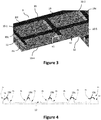
- the figure 4 is an illustrative illustration of a possible longitudinal section of the gripping device 1 of the figure 1 , at the central keys 10-4 to 10-6 and 11-2. It illustrates an embodiment of the various profiles P1 to P4 for the keys.
- the figure 3 also illustrates the different profiles P3 and P4 of keys 10-1, 10-2, 10-4 and 10-5.
- a first profile P1 makes it possible to determine the right side edge of the input device.
- the P2 profile of the correction key introduces himself in the form of a vertical slope.
- the P3 profiles of the numeric keys are generally wave-shaped. They are different from the P2 profile, allowing the visually impaired user to differentiate the number keys from the function keys.
- the left outer profile P4 is also different from the right outer profile P1, in particular by the size of the plates (P14 vs Pl1), thus allowing the user to determine the orientation of the device when it is placed on the touch screen.
- the stud 13 of the five button 10-5 is also visible on this button and allows the five button to be quickly identified.
- the plate 30 is made of an electrically insulating material, so as not to emit a stray capacitance that is difficult to control.
- the plate is made of rigid, transparent plastic.
- the lower face 18 of the plate 30 comprises, in each of its four angles, a foot 16-1 to 16-4 which is generally flat with a thickness between 0.1 and 0.4 mm.
- the feet aim to ensure that it is the contact pads 15-1 and 15-2 which press on the touch screen 24, even if the plate 30 is a little twisted.
- the lower face comprises only two feet, those referenced 16-1 and 16-2 (that is to say those located in the two "top” angles, in the plane of the upper face of the plate. ). This prevents limping of the gripper, whether the plate is concave or convex.
- the lower face 18 of the plate 30 comprises one or more anti-slip feet 16-1 'and 16-2', made of a non-slip material. It is for example a material with multiple pins, which behaves like the filaments of the Gecko (the lizard). With this (s) anti-slip foot (s), once the input device has been placed on the touch screen 24, it does not move during input. This is particularly effective on glass.
- the lower face 18 of the plate 30 comprises, for example in its middle, a suction cup (40) integral with the lower face and intended to come in. contact with the touch screen 24.
- a suction cup (40) integral with the lower face and intended to come in. contact with the touch screen 24.
- the plate 30 is made of translucent non-conductive silicone, the hardness of which is for example between 60 and 90 Shores A.
- the plate can be deformed and adapt perfectly to the flatness of the touch screen ( and therefore a priori not to require a foot).
- the production of the silicone plate allows it to adhere to the touch screen, to be deformable under its weight and with good shape memory.
- the plate 30 is for example approximately the dimensions of a bank card (54 mm ⁇ 85 mm, to within a few millimeters). This makes it possible to place the input device 1 in a wallet or a card holder, in the same place as the bank card.
- the lower angles, left and right, of the upper face 17 of the plate 3 do not include any key.
- the two contact pads 15-1 and 15-2 are positioned in the corresponding (that is to say superimposed) zones of the lower face 18 of the plate 30.
- the two contact pads 15-1 and 15-2 are very flexible and flat, so as to maximize their surface in contact with the touch screen 24. They have for example the shape of a disc with a diameter of between 6 and 8 mm. . They are for example made of conductive silicone, the hardness of which is between 40 and 80 Shores A. Other techniques can be used to make contact pads: metal parts, designs made with conductive inks (directly on the underside of the the plate, or on a film itself then transferred to the underside of the plate), etc.
- the center distance between the contact pads is determined and known to the terminal controller, which can thus, after having detected the two contact pads (see method described below), detect that the input device 1 has been affixed to the panel. tactile 24.
- the controller can also deduce therefrom the modulo 180 ° position and orientation of the input device 1 on the tactile screen 24.
- the input device comprises at least three contact pads 15-1, 15-2 and 15-3.
- the controller can detect the orientation of the input device without modulo 180 °.
- three contact pads there is less confusion possible with a center distance of fingers placed on the touch screen.
- the two contact pads 15-1 and 15-2 have different shapes (for example disc for one and rectangle for the other).
- the controller can also detect the orientation of the input device without modulo 180 °.
- the input device comprises a single contact pad, having a particular shape (for example oblong or rectangular, with a sufficient length).
- the controller can identify the single contact patch and know its orientation (modulo 180 °); and from there also know the orientation (modulo 180 °) of the input device when it is affixed to the touch screen.
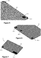
- the network of conductive tracks 19 is shown in black. It comprises tracks arranged in lines 191 and in columns 19c, which form a grid over a substantial part of the upper face 17 of the plate 30.
- the network of conductive tracks 19 is electrically connected to the contact pads 15-1 and 15-2 via electrical connections 14-1 (only one connection is visible on the figure 2A ) (for example sections of conductive tracks and via).
- the contact pads 15-1 and 15-2 form the thickness of the plate (in this case, the via are not necessary).
- the network of conductive tracks 19 is formed in the upper part of the grid of profiles.
- each conductive track 19c, 191 is formed in the upper part of one of the profiles P1 to P4.
- the network of conductive tracks 19 must extend over a sufficiently large area, thus making it possible to act with more nodes of the matrix of electrodes (row / column intersection) of the touch screen, and therefore to have a load which varies during capacitive sweeps. This is particularly the case when the network of conductive tracks 19 is formed in the upper part of the grid of profiles and when the plate 30 is substantially the dimensions of a bank card (that is to say approximately 54 mm x 85 mm).
- the network of conductive tracks 19 and the lower face 18 of the plate 30 are separated by a distance (height denoted e1 on the figure 3 ) between 1.5 mm and 4.5 mm.
- the conductive tracks have a width of between 0.5 mm and 2 mm.
- the network of conductive tracks has a low capacitance, which allows it both to interact with the touch screen during capacitive scans (and to move the charges of the network of conductive tracks, which avoids a recalibration of the screen. touch by the controller), but also not to be detected as a significant variation in capacitance (which would cause false detection of a significant press).
- the minimum value of the height e1 (1.5 mm). Indeed, since the input device has a free placement on the touch screen, and that the positions of the nodes of the matrix of electrodes (intersection rows / columns) of the touch screen are not known, we can have an alignment perfect of a conductive track with an electrode (row or column) of the touch screen. If this is the case, and if the distance between this conductive track and this electrode is small, then the capacitance between these two elements (track and electrode) will increase significantly, which is not desirable. With the minimum value of the height e1, we remain with a low capacitance for the network of conductive tracks.
- the maximum value of the height e1 (4 mm) can (in theory) be exceeded, but here it is the ergonomics, to access the bottom of the keys, which is affected.
- the range of values of the height e1 is respected, but the network of conductive tracks 19 is not formed in the upper part of the grid of profiles. It is for example formed, on the plane of the upper face 17 of the plate 30, in a zone adjoining and / or surrounding that where the keys of the entry zone matrix are located. In this case, the total area of the plate 30 can be increased over the particular implementation illustrated.
- the network of conductive tracks has a resistance, between contact pads, between 20 ⁇ and 150 k ⁇ . A relatively low resistance improves the responsiveness of the input device 1.
- the network of conductive tracks 19 is configured so that, when the input device 1 is affixed to the touch screen, and even in the absence of a finger pressing on the network of conductive tracks, the network of conductive tracks interacts with the touch screen during capacitive scanning cycles, which prevents a recalibration of the reference values (which itself would prevent each of the contact pads 15-1 and 15-2 from being detected as a significant press), without the network of conductive tracks 19 itself being detected as a significant press.
- the capacitance is defined in proportion to the facing surface, and inversely in proportion to the distance of the insulator. Consequently, the contact pads 15-1 and 15-2, very close to the electrodes of the touch screen 24, have a measurable capacity (of the order of a stylus), allowing them to each be detected as a support. significant, while the network of conductive tracks 19 (greater height e1, and with thin conductive tracks) has a much lower capacitance, allowing it not to be detected as a significant support.
- the network of conductive tracks 19 has another important characteristic: it extends over a larger area than the contact pads, and therefore, even if its capacity is low, it interacts with several nodes of the electrode matrix ( row / column intersection) of the touch screen.
- the fact that the conductive tracks are connected in a network allows charges to flow freely therein.
- charges come and go in the network of conductive tracks, as well as between the contact pads and the network of conductive tracks. This therefore changes very slightly the load of the network of conductive tracks and of the contact pads. Therefore, for the relevant nodes of the electrode array (i.e.
- the controller measures variations in capacitance (with respect to values reference) which are not fixed over successive cycles, and therefore decides not to recalibrate the touch screen (i.e. to modify the reference values for the nodes concerned). This non-recalibration allows each of the contact pads 15-1 and 15-2 to continue to be detected as a significant press.
- the figure 10 illustrates a data entry device 100, according to a variant of the first embodiment of the invention, in “portrait” format, particularly suitable for use with touch panels also of “small format” portrait type (for which, the data entry device 1 of the first embodiment, in “landscape” format, would not be usable). Its operation is exactly the same as that of the first embodiment.
- the ten number keys 10-0 'to 10-9' (still on four rows and three columns) are arranged above (and no longer on the left) of the three functional keys 11-1 'to 11-3', themselves arranged on a row (and no longer on a column).
- the lower angles, left and right, of the upper face 17 of the plate 3 do not include any key. It is in the corresponding (that is to say superimposed) zones of the lower face 18 of the plate 30 that the two contact pads 15-1 'and 15-2' are positioned.
- the center distance between contact pads is not the same as in the first embodiment.
- the terminal controller which knows the center distance between contact pads of each of the types of input device 1, 100, can detect which type of input device has been affixed to the touch screen (and thus deduce the position each of the keys of the input device affixed).
- a corner of the input device (e.g. top right, see figure 10 ) is bevelled and allows the user to orient the input device without possible confusion. This prevents the user from placing the input device horizontally.
- the figure 8 shows an example of the structure of terminal 2 of the figure 1 , implementing a data entry method according to the invention (for example the particular embodiment described below in relation to the figure 9 ).
- the terminal 2 comprises a touch screen 24 (see description above), a random access memory 22 (for example a RAM memory), a processing unit 61 (notably forming the controller (control unit) of the touch screen 24; see description above), equipped for example with a processor, and controlled by a computer program 230 stored in a read only memory 23 (for example a ROM memory or a hard disk).
- a computer program 230 stored in a read only memory 23 (for example a ROM memory or a hard disk).
- the code instructions of the computer program 230 are for example loaded into the random access memory 22 before being executed by the processor of the processing unit 21.
- FIG 8 illustrates only one particular way, among several possible, of carrying out the algorithm detailed below in relation to the figure 9 .
- the technique of the invention can be carried out equally well on a reprogrammable computing machine (a PC computer, a DSP processor or a microcontroller) executing a program comprising a sequence of instructions, or on a dedicated computing machine (for example a set of logic gates such as an FPGA or ASIC, or any other hardware module).
- a reprogrammable computing machine a PC computer, a DSP processor or a microcontroller
- a program comprising a sequence of instructions
- a dedicated computing machine for example a set of logic gates such as an FPGA or ASIC, or any other hardware module.
- the corresponding program (that is to say the sequence of instructions) can be stored in a removable storage medium (such as for example a floppy disk, CD-ROM or DVD-ROM) or not, this storage medium being partially or totally readable by a computer or a processor.
- a removable storage medium such as for example a floppy disk, CD-ROM or DVD-ROM
- the figure 9 presents a flowchart of a method according to a particular embodiment of the invention, executed by the terminal 2.
- a step 91 the terminal detects an affixing of the data entry device 1 on the touch screen 24. This first detection is based on a detection of the contact pad or pads 15-1 and 15-2.
- the controller of the touch screen detects the two (or three) contact pads, and possibly one or more significant presses if the user holds the input device in hand and one of his fingers touches the touch screen. As explained above, this detection is possible because the contact pads are electrically conductive and in direct contact. with the touch screen. The level of detection of the contact pads is acceptable because it is lower than if one pressed with a finger, but of a level comparable to that of a stylus. It is recalled that the network of conductive tracks is not detected but makes it possible to avoid a recalibration of the touch screen (which would prevent the detection of the contact pads).
- the distance (s) between contact pads being known to the controller (with some variations), the latter is able to recognize that it is a input device 1 which has been installed.
- the controller also checks that each of the input zones (keys) 10-0 to 10-9 and 11-1 to 11-3 is present at least partially in an active zone of the touch screen 24. We consider for example if 80% of a key is in the active area, then this is still acceptable.
- step 92 if the determinations and verifications of step 91 have been carried out successfully, the terminal switches to an input mode suitable for the data input device (hereinafter called “blind mode”). To acknowledge the correct presence of the input device and confirm to the user the switching to blind mode, an audible notification is emitted by the terminal. In addition, in order to secure the next data entry phase, the terminal erases the virtual keyboard on the touch screen. In addition, in blind mode, the setting of the touch screen is for example such that it makes it possible to detect lower levels when entering the PIN code. This makes it possible to compensate, if necessary, for the fact that the user's finger is in contact with the touch screen 24 via the input device 1.
- a step 93 the terminal detects an entry of data by the user. This second detection is based on the detection of one or more presses of a user's finger on the keys of the input device.
- the controller detects four successive presses of the number keys 10-0 to 10-9, followed by a press of the validation key 11-3. On exiting the PIN code entry, you switch back to standard settings ("normal mode").
- Another way to filter support is to have force detection. In this case, it is not necessary to have a filtering on the duration of the pressure. In addition or not to the force detection, a haptic effect can be added to the keyboard.
- Exiting blind mode can be done in several ways. If a contact pad is no longer detected by the controller or if the controller detects that the keys are no longer in the active zone of the touch screen, the user is notified, for example by a "negative" sound feedback ( long grave) that we exit the blind mode, and that we return to a display according to the classic mode.
- the input device can move and we are always able to detect it (with its orientation) and therefore to define the key (s) supported.
Description
La présente technique se rapporte au domaine de la saisie de données sur des terminaux (téléphones mobiles, ordinateurs, tablettes, terminaux de paiement, distributeurs automatiques de billets (DAB), terminaux de communication qui se transforment provisoirement en terminaux de paiement, etc.).The present technique relates to the field of data entry on terminals (mobile telephones, computers, tablets, payment terminals, automatic teller machines (ATM), communication terminals which temporarily transform into payment terminals, etc.) .
Plus précisément, la présente technique concerne un système de saisie de données comprenant une dalle tactile d'un terminal et un dispositif de saisie de données destiné à être apposé sur cette dalle tactile (aussi appelée « écran tactile », ou encore « touch screen » ou « touch panel » en anglais).More precisely, the present technique relates to a data entry system comprising a touch screen of a terminal and a data entry device intended to be affixed to this touch screen (also called “touch screen”, or also “touch screen”. or "touch panel" in English).
La présente technique s'applique notamment, mais non exclusivement, à la saisie de codes confidentiels ou de codes d'identification personnels (ou code PIN pour « Personal Identification Number » en anglais) sur une dalle tactile d'un terminal, par exemple pour les personnes malvoyantes.This technique applies in particular, but not exclusively, to the entry of confidential codes or personal identification codes (or PIN code for “Personal Identification Number” in English) on a touch screen of a terminal, for example for visually impaired people.
Les écrans tactiles sont largement utilisés pour saisir des données au sein de systèmes informatisés de traitement de données. Par exemple, les téléphones mobiles, les ordinateurs, les tablettes, ou encore les terminaux de paiement et les distributeurs automatiques de billets (DAB) disposent d'écrans tactiles pour faciliter la saisie des données par les utilisateurs.Touch screens are widely used for entering data into computerized data processing systems. For example, mobile phones, computers, tablets, as well as payment terminals and automatic teller machines (ATMs) have touch screens to facilitate data entry by users.
Pour effectuer une saisie, un utilisateur peut sélectionner une ou plusieurs touches (associées chacune à un caractère alphanumérique) sur un clavier virtuel affiché sur l'écran tactile, en utilisant un doigt ou un stylet. Il n'est ainsi plus nécessaire de disposer d'un clavier physique pour saisir des données. Cependant, la saisie des données avec un clavier virtuel présente des inconvénients, notamment pour les personnes malvoyantes, mais également pour les personnes technophobes ou peu coutumières des usages numériques. Notamment, à la différence des claviers physiques, les claviers virtuels sont affichés sur un écran plat et ne permettent pas à certains utilisateurs (notamment aux personnes malvoyantes) de se repérer spatialement sur les touches virtuelles.To make an entry, a user can select one or more keys (each associated with an alphanumeric character) on a virtual keyboard displayed on the touch screen, using a finger or a stylus. It is therefore no longer necessary to have a physical keyboard to enter data. However, entering data with a virtual keyboard has drawbacks, especially for visually impaired people, but also for technophobic people or people unfamiliar with digital uses. Notably, unlike physical keyboards, virtual keyboards are displayed on a flat screen and do not allow some users (especially visually impaired people) to locate themselves spatially on the virtual keys.
Cet inconvénient est en particulier gênant pour les terminaux de paiement ou les distributeurs automatiques de billets (DAB) qui disposent d'un écran tactile. En effet, lorsqu'un utilisateur utilise sa carte bancaire pour effectuer un paiement ou pour retirer des billets, il doit saisir son code PIN pour s'authentifier. Il n'est pas possible pour une personne malvoyante de saisir son code PIN sur un clavier virtuel affiché sur un écran tactile.This drawback is particularly troublesome for payment terminals or automatic teller machines (ATMs) which have a touch screen. Indeed, when a user uses his bank card to make a payment or to withdraw tickets, he must enter his PIN code to authenticate himself. It is not possible for a visually impaired person to enter their PIN code on a virtual keyboard displayed on a touch screen.
Une directive européenne (en cours de rédaction) obligera prochainement les commerçants et banquiers à fournir une solution pour les personnes malvoyantes. La solution de l'état de la technique consiste à fournir toujours un clavier physique électronique relié à un terminal de paiement, même si un clavier virtuel est disponible sur l'écran tactile. Le coût de fabrication des terminaux de paiement ou des distributeurs automatiques de billets (DAB) est ainsi augmenté, sans que la solution soit réellement intéressante, notamment des points de vue technique et esthétique. En effet, le clavier physique destiné aux personnes malvoyantes doit être sécurisé pour éviter le piratage, augmentant le coût, et ce clavier n'est généralement pas esthétiquement intégré dans la solution tactile.A European directive (currently being drafted) will soon oblige traders and bankers to provide a solution for the visually impaired. The solution of the state of the art consists in always providing an electronic physical keyboard connected to a payment terminal, even if a virtual keyboard is available on the touch screen. The cost of manufacturing payment terminals or automatic teller machines (ATM) is thus increased, without the solution being really attractive, in particular from a technical and aesthetic point of view. Indeed, the physical keyboard intended for visually impaired people must be secure to avoid hacking, increasing the cost, and this keyboard is generally not aesthetically integrated into the touch solution.
Par ailleurs, en sus des problématiques d'esthétique et de coût, il existe également une problématique importante de sécurité. En effet, à la différence d'un utilisateur standard, les personnes vulnérables, comme les personnes malvoyantes, doivent souvent solliciter l'aide de personnes qu'elles ne connaissent pas nécessairement. Ceci est une grande source de stress pour ces personnes vulnérables. Lorsqu'il s'agit par exemple de taper un code PIN, et donc de révéler une information sensible, il est nécessaire de s'assurer que la personne dont on sollicite éventuellement l'aide ne va pas tenter de conserver cette information pour une utilisation frauduleuse.Furthermore, in addition to aesthetic and cost issues, there is also an important safety issue. Indeed, unlike a standard user, vulnerable people, such as visually impaired people, often have to seek help from people they do not necessarily know. This is a great source of stress for these vulnerable people. When it comes to entering a PIN code, for example, and therefore revealing sensitive information, it is necessary to ensure that the person whose help you may be seeking will not attempt to keep this information for use. fraudulent.
De la même manière, de nombreux utilisateurs ne sont pas en mesure de détecter et combattre efficacement les applications et logiciels espions qui sont installés sur leurs terminaux de communication. Or de plus en plus de terminaux de communication sont utilisés à des fins de saisie d'informations confidentielles et notamment d'informations de paiement (code PIN, comptes bancaires, etc.). Pour contrer ces problèmes de fraude, les solutions existantes proposent un affichage aléatoire du clavier virtuel ; dans un tel affichage aléatoire, les touches du clavier sont disposées aléatoirement et l'utilisateur doit identifier les touches pour pouvoir saisir ses données confidentielles (par exemple le code PIN). Une application sécurisée, installée sur le terminal de communication, se charge de réaliser la correspondance entre les zones de saisie de l'utilisateur et les caractères correspondants. On comprend bien qu'une telle manière de faire n'est pas adaptée pour de nombreux utilisateurs, et notamment pour les personnes malvoyantes ou plus généralement pour les personnes en rupture par rapport à la numérisation de ces opérations de saisies sur écran tactile.Likewise, many users are unable to effectively detect and combat spyware and applications that are installed on their communication terminals. However, more and more communication terminals are used for the purpose of entering confidential information and in particular payment information (PIN code, bank accounts, etc.). To counter these fraud problems, the existing solutions offer a random display of the virtual keyboard; in such a random display, the keys of the keyboard are arranged at random and the user must identify the keys in order to be able to enter his confidential data (for example the PIN code). A secure application, installed on the communication terminal, is responsible for making the correspondence between the user input zones and the corresponding characters. It will be understood that such a way of proceeding is not suitable for many users, and in particular for visually impaired people or more generally for people who are out of step with the digitization of these touch screen input operations.
Il existe ainsi un besoin de fournir une solution permettant aux utilisateurs de saisir des données confidentielles sur des terminaux (terminaux de paiement et terminaux de communication par exemple) comprenant un écran tactile, en assurant la sécurité des données saisies, tout en réduisant le coût de cette solution et conservant l'aspect esthétique engendré par l'utilisation d'écran tactiles.There is thus a need to provide a solution allowing users to enter confidential data on terminals (payment terminals and communication terminals for example) comprising a touch screen, while ensuring the security of the data entered, while reducing the cost of this solution and retaining the aesthetic appearance generated by the use of touch screens.
L'invention permet notamment de faciliter les opérations de saisie de données sur un écran tactile (aussi appelé dalle tactile), notamment pour les personnes malvoyantes. La solution de l'invention n'est cependant pas limitée à une utilisation par une personne malvoyante et peut être utilisée par toute personne pour la saisie, de manière simple, ergonomique et sécurisée, d'informations (confidentielles ou non) sur un écran tactile.The invention makes it possible in particular to facilitate data entry operations on a touch screen (also called a touch screen), in particular for visually impaired people. The solution of the invention is however not limited to use by a visually impaired person and can be used by any person for entering, in a simple, ergonomic and secure manner, information (confidential or not) on a touch screen. .
Dans un mode de réalisation particulier de l'invention, il est proposé un système de saisie de données comprenant une dalle tactile d'un terminal et un dispositif de saisie de données destiné à être apposé sur ladite dalle tactile, ladite dalle tactile étant capacitive, comprenant des électrodes en lignes et en colonnes formant une matrice d'électrodes comprenant des nœuds, et étant pilotée par une unité de contrôle configurée pour effectuer des cycles de balayage capacitif et de mesure des variations de capacité des nœuds par rapport à des valeurs de référence, détecter des appuis significatifs sur la dalle tactile en fonction des variations de capacité mesurées, et ré-étalonner les valeurs de référence en fonction des variations de capacité mesurées. Le système comprend :
- une plaque globalement parallélépipédique comprenant une face inférieure, globalement plane, d'apposition du dispositif sur la dalle tactile, et une face supérieure comprenant une matrice de zones de saisie formant clavier, les zones de saisie ayant une épaisseur configurée pour permettre une détection d'un doigt par la dalle tactile quand le dispositif est apposé sur la dalle tactile ;
- au moins une pastille de contact, plane, conductrice électriquement et solidaire de la face inférieure, ladite au moins une pastille de contact ayant une capacité lui permettant d'être détectée comme appui significatif ; et
- un réseau de pistes conductrices, s'étendant sur au moins une partie de la face supérieure et étant relié électriquement à ladite au moins une pastille de contact, le réseau de pistes conductrices ayant une capacité lui permettant de ne pas être détecté comme appui significatif et occupant une surface d'une part plus grande que la surface occupée par ladite au moins une pastille de contact et d'autre part suffisante pour que, lors des cycles de balayage capacitif, le réseau de pistes conductrices interagisse avec plusieurs nœuds de la matrice d'électrodes sous la forme de charges qui vont et viennent dans le réseau de pistes conductrices ainsi qu'entre ladite au moins une pastille de contact et le réseau de pistes conductrices, ce qui change la charge du réseau de pistes conductrices et de ladite au moins une pastille de contact et par conséquent, pour les nœuds de la matrice d'électrodes situés en regard du réseau de pistes conductrices et de ladite au moins une pastille de contact, dits nœuds concernés, l'unité de contrôle mesure des variations de capacité qui ne sont pas fixes sur des cycles successifs et décide donc de ne pas procéder à un réétalonnage des valeurs de référence pour les nœuds concernés.
- a generally parallelepipedal plate comprising a lower face, generally planar, for affixing the device to the touch screen, and an upper face comprising a matrix of input zones forming a keyboard, the input zones having a thickness configured to allow detection of a finger by the touch screen when the device is affixed to the touch screen;
- at least one contact pad, plane, electrically conductive and integral with the lower face, said at least one contact pad having a capacitance allowing it to be detected as a significant support; and
- a network of conductive tracks, extending over at least part of the upper face and being electrically connected to said at least one contact pad, the network of conductive tracks having a capacitance allowing it not to be detected as a significant support and occupying an area on the one hand larger than the area occupied by said at least one contact pad and on the other hand sufficient so that, during capacitive scanning cycles, the network of conductive tracks interacts with several nodes of the matrix d 'electrodes in the form of charges which move back and forth in the array of conductive tracks as well as between said at least one contact pad and the array of conductive tracks, which changes the charge of the array of conductive tracks and of said at least a contact pad and therefore, for the nodes of the array of electrodes located opposite the network of conductive tracks and said at least one contact pad, d its nodes concerned, the control unit measures variations in capacity which are not fixed over successive cycles and therefore decides not to proceed with a recalibration of the reference values for the nodes concerned.
La solution proposée repose donc sur une approche tout à fait nouvelle et inventive, consistant à fournir un dispositif de saisie destiné à être apposé sur la dalle tactile d'un terminal, pour obtenir un système dont le fonctionnement est le suivant :
- grâce à la détection de la ou les pastilles de contact (ou « contact pad » en anglais), présente(s) sur la face inférieure du dispositif de saisie et venant en contact avec la dalle tactile quand le dispositif est apposée sur celle-ci, le terminal peut détecter cette apposition, ainsi que l'orientation du dispositif sur la dalle tactile (plusieurs solutions pour déterminer cette orientation sont détaillés ci-après) ; puis
- connaissant l'orientation du dispositif sur la dalle tactile, et donc la position sur la dalle tactile de chacune des zones de saisie (formant touches de saisie) du dispositif, le terminal peut, à chaque fois qu'il détecte un appui d'un doigt de l'utilisateur sur la dalle tactile à travers l'une des zones de saisie du dispositif, déterminer à quel caractère de clavier (par exemple parmi les chiffres 0 à 9) ou fonction de clavier (par exemple parmi « annulation », « effacement » et « validation ») correspond cet appui.
- thanks to the detection of the contact pad (s) (or “contact pad” in English), present on the underside of the input device and coming into contact with the touch screen when the device is affixed to it , the terminal can detect this affixing, as well as the orientation of the device on the touch screen (several solutions for determining this orientation are detailed below); then
- knowing the orientation of the device on the touch screen, and therefore the position on the touch screen of each of the input zones (forming input keys) of the device, the terminal can, each time it detects a press of a user's finger on the touch screen through one of the input zones of the device, determine which keyboard character (for example among the digits 0 to 9) or keyboard function (for example among "cancellation", " deletion ”and“ validation ”) corresponds to this press.
Comme détaillé par la suite, en relation avec les figures, la détection de la ou les pastilles de contact (en tant qu'appui(s) significatifs) sur la dalle tactile) est maintenue possible grâce au réseau de pistes conductrices présent sur la face supérieure du dispositif de saisie et relié électriquement à la ou les pastilles de contact. En effet, le réseau de pistes conductrices permet d'éviter que le terminal effectue un réétalonnage de la dalle tactile, c'est-à-dire un réétalonnage (une mise à jour), au bout de quelques cycles de balayage capacitif, d'une ou plusieurs des valeurs de référence associées aux nœuds de la matrice d'électrodes de la dalle tactile capacitive. Le mécanisme de réétalonnage de la dalle tactile vise à compenser (et si possible faire disparaître), dans les résultats de détection, tout objet électriquement conducteur (par exemple une goutte d'eau) qui vient en contact avec la dalle tactile et qui a un comportement trop stable, et constitue donc un bruit additionnel à supprimer (contrairement à un appui du doigt de l'utilisateur). Par conséquent, s'il n'était pas empêché, le réétalonnage de la dalle tactile rendrait « invisibles » (c'est-à-dire non détectées) la ou les pastilles de contact (en tant que bruit additionnel). Le mécanisme de réétalonnage de la dalle tactile, et la manière dont le réseau de pistes conductrices permet de l'éviter, sont présentés en détail plus bas.As detailed below, in relation to the figures, the detection of the contact pad (s) (as significant support (s) on the touch screen) is kept possible thanks to the network of conductive tracks present on the face. upper part of the input device and electrically connected to the contact pad (s). Indeed, the network of conductive tracks makes it possible to prevent the terminal from carrying out a recalibration of the touch screen, that is to say a recalibration (an update), after a few cycles of capacitive scanning, of one or more of the reference values associated with the nodes of the array of electrodes of the capacitive touch screen. The touchscreen recalibration mechanism aims to compensate (and if possible eliminate), in the detection results, any electrically conductive object (for example a drop of water) which comes in contact with the touchscreen and which has a too stable behavior, and therefore constitutes an additional noise to be removed (unlike pressing the user's finger). Therefore, if not prevented, recalibration of the touch screen would render the contact pad (s) "invisible" (ie not detected) (as additional noise). The mechanism for recalibrating the touch screen, and how the network of conductive tracks avoids it, are discussed in detail below.
Ainsi, la solution proposée permet de s'affranchir de l'utilisation d'un clavier physique, tout en permettant une saisie d'informations :
- simple et ergonomique, grâce à un repérage aisé des zones de saisie du dispositif (notamment mais non exclusivement par une personne malvoyante), et
- sécurisée, puisqu'elle ne nécessite pas la sollicitation d'un tiers par l'utilisateur et qu'il n'y a pas de traces de doigts sur la dalle tactile (qui pourraient aider un fraudeur à retrouver un code venant d'être saisi). La sécurisation peut encore être accrue dans le cas (décrit en détail plus bas) où après avoir détecté l'apposition du dispositif sur la dalle tactile, le terminal bascule dans un mode de saisie adapté (appelé ci-après « mode aveugle ») dans lequel aucun clavier virtuel n'est affiché sur la dalle tactile.
- simple and ergonomic, thanks to easy identification of the input zones of the device (in particular but not exclusively by a visually impaired person), and
- secure, since it does not require the solicitation of a third party by the user and there are no fingerprints on the touch screen (which could help a fraudster to find a code that has just been entered). The security can be further increased in the case (described in detail below) where after having detected the affixing of the device on the touch screen, the terminal switches to a suitable input mode (hereinafter called "blind mode") in which no virtual keyboard is displayed on the touch screen.
En outre, le dispositif de saisie peut être un objet personnel, ce qui est un avantage en matière d'hygiène pour un objet qui se touche. Dans le cas d'un objet partagé, il peut être envisagé que le dispositif de saisie soit en matière « anti bactérienne » (par exemple une matière avec un additif type ion argent, comme dans les réfrigérateurs).In addition, the gripping device can be a personal item, which is a hygienic advantage for an object that touches itself. In the case of a shared object, it can be envisaged that the input device is made from an “anti-bacterial” material (for example a material with a silver ion type additive, as in refrigerators).
Un avantage additionnel d'un accessoire individuel, est que l'utilisateur est assuré qu'aucun dispositif espion n'a été ajouté dans le dispositif pour venir lui récupérer son code PIN.An additional advantage of an individual accessory is that the user is assured that no spy device has been added to the device to come and retrieve his PIN code.
Dans une première implémentation particulière, la face inférieure comprend au moins deux pastilles de contact.In a first particular implementation, the lower face comprises at least two contact pads.
Ainsi, quand le dispositif de saisie est apposé sur la dalle tactile, le terminal détecte les pastilles de contact, et par analyse des résultats de cette détection (nombre et forme des pastilles, distance entre elles) en déduit la présence, la position et l'orientation modulo 180° du dispositif sur la dalle tactile. Ceci suppose que le terminal connaît le nombre de pastilles de contact, leurs formes, les distances entre celles-ci, et leurs positions au sein de la géométrie du dispositif de saisie.Thus, when the input device is affixed to the touch screen, the terminal detects the contact pads, and by analysis of the results of this detection (number and shape of the pads, distance between them) deduces the presence, position and location. 180 ° modulo orientation of the device on the touch screen. This assumes that the terminal knows the number of contact pads, their shapes, the distances between them, and their positions within the geometry of the input device.
Si le terminal est petit, on peut supposer que le dispositif de saisie est bien positionné. Donc, dans ce cas, on peut supposer une orientation (levée de l'ambiguïté du modulo 180°). C'est acceptable, car lors de l'appui sur une touche, si cela ne fonctionne pas, on s'en rendra compte de suite.If the terminal is small, it can be assumed that the input device is well positioned. So, in this case, we can assume an orientation (removal of the ambiguity of modulo 180 °). This is acceptable, because when you press a key, if it does not work, you will notice it immediately.
Dans une variante, le dispositif de saisie comprend une unique pastille de contact, ayant une forme particulière (par exemple oblongue ou rectangulaire, avec une longueur suffisante) permettant de l'identifier et d'en connaître l'orientation (et de là également l'orientation du dispositif de saisie).In a variant, the input device comprises a single contact pad, having a particular shape (for example oblong or rectangular, with a sufficient length) making it possible to identify it and to know its orientation (and hence also the orientation of the input device).
Selon une caractéristique particulière de la première implémentation, lesdites au moins deux pastilles de contact possèdent des formes différentes.According to a particular characteristic of the first implementation, said at least two contact pads have different shapes.
Ainsi, le terminal peut détecter l'orientation du dispositif de saisie sans le modulo 180°. En d'autres termes, on peut déduire la bonne orientation, même avec deux pastilles de contact, à condition que la deuxième pastille soit de forme très différente de la première (comme un cercle (ou un carré) pour l'une, et un rectangle dont la longueur est deux fois sa largeur pour l'autre).Thus, the terminal can detect the orientation of the input device without modulo 180 °. In other words, we can deduce the correct orientation, even with two contact pads, provided that the second pad is very different in shape from the first (like a circle (or a square) for one, and a rectangle whose length is twice its width for the other).
Dans une deuxième implémentation particulière, la face inférieure comprend au moins trois pastilles de contact.In a second particular implementation, the lower face comprises at least three contact pads.
Ainsi, le terminal peut détecter l'orientation du dispositif de saisie sans le modulo 180°. En effet, l'ensemble des au moins trois pastilles de contact forment une signature (géométrie triangulaire particulière ; triangle plat dans une implémentation particulière) propre au dispositif de saisie de données, qui peut être détectée et reconnue par le terminal quand le dispositif est apposé sur la dalle tactile.Thus, the terminal can detect the orientation of the input device without modulo 180 °. Indeed, the set of at least three contact pads form a signature (particular triangular geometry; flat triangle in a particular implementation) specific to the data entry device, which can be detected and recognized by the terminal when the device is affixed. on the touch screen.
Selon une caractéristique particulière, la matrice de zones de saisie formant clavier comprend un ensemble de touches de saisie qui sont globalement planes, formées sur la surface supérieure et séparées entre elles par une grille de profilés de hauteurs et/ou de formes prédéterminées, et le réseau de pistes conductrices est formé en partie haute de la grille de profilés.According to one particular characteristic, the matrix of input zones forming a keyboard comprises a set of input keys which are generally flat, formed on the upper surface and separated from each other by a grid of profiles of predetermined heights and / or shapes, and the network of conductive tracks is formed in the upper part of the grid of profiles.
Ainsi, l'utilisateur (notamment une personne malvoyante) se repère à l'aide de la grille de profilés qui délimitent les touches les unes par rapport aux autres, en fonction des formes et/ou des hauteurs de ces profilés. Dans une implémentation particulière, la touche cinq n'a pas la même hauteur que les autres touches numériques et/ou la hauteur des touches numériques n'est pas la même que celle des touches de fonction, pour faciliter encore le repérage des touches par l'utilisateur. Dans une implémentation particulière, les touches de saisie ne comprennent aucune indication spécifique quant à leur fonction, de façon à renforcer la sécurité en évitant qu'une personne malveillante surveille les touches qui sont utilisées pour la saisie.Thus, the user (in particular a visually impaired person) locates himself with the aid of the grid of profiles which delimit the keys with respect to one another, according to the shapes and / or the heights of these profiles. In a particular implementation, the five key does not have the same height as the other number keys and / or the height of the number keys is not the same as that of the function keys, to make it even easier to identify the keys by l 'user. In a particular implementation, the input keys do not include any specific indication as to their function, so as to enhance security by preventing a malicious person from monitoring the keys that are used for input.
Plusieurs avantages découlent de la formation du réseau de pistes conductrices en partie haute de la grille de profilés :
- le réseau de pistes conductrices peut s'étendre sur une partie substantielle de la face supérieure du dispositif de saisie (car en pratique la grille de profilés occupe la quasi-totalité de la face supérieure du dispositif de saisie), et donc interagir avec plusieurs nœuds de la matrice d'électrodes de la dalle tactile (le réseau de pistes conductrices provoque des transferts de charge, synchrones du balayage de la dalle et donc non stables) et donc meilleure efficacité pour éviter que le terminal effectue un réétalonnage de la dalle tactile) ;
- dans la phase de saisie de données par l'utilisateur (c'est-à-dire après que le terminal a détecté la présence et l'orientation du dispositif de saisie sur la dalle tactile), le réseau de pistes conductrices améliore la détection de la ou les pastilles de contact, puisque pour toucher les touches de saisie le doigt de l'utilisateur touche (ou approche s'il y a un vernis protecteur) le réseau de pistes conductrices, qui est lui-même en contact électrique avec la ou les pastilles de contact. Par conséquent, lors des cycles de balayage capacitif, des charges ne sont pas transférées (ou attirées) seulement par la ou les pastilles de contact mais également par le doigt de l'utilisateur. Donc la modification locale du champ électrique est plus importante (on magnifie ainsi le signal aux localisations des pastilles) que pendant la phase initiale de détection du dispositif de saisie (au cours de laquelle l'utilisateur ne touche (ou n'approche) généralement pas/plus le réseau de pistes conductrices après avoir apposé le dispositif de saisie sur la dalle tactile). On rappelle que le doigt n'a pas besoin de toucher : on a une capacité entre le doigt de l'utilisateur et le réseau de pistes conductrices. Cela se comporte comme deux capacités en série : une première capacité entre la dalle tactile et les pastilles de contact, une deuxième capacité entre le réseau de pistes conductrices et le doigt de l'utilisateur, et entre ces première et deuxième capacités la résistance des éléments conducteurs reliant les pastilles de contact et le réseau de pistes conductrices.
- the network of conductive tracks can extend over a substantial part of the upper face of the input device (because in practice the grid of profiles occupies almost all of the upper face of the input device), and therefore interact with several nodes of the electrode array of the touch screen (the network of conductive tracks causes charge transfers, synchronous with the scanning of the screen and therefore not stable) and therefore better efficiency to prevent the terminal from performing a recalibration of the touchpad) ;
- in the data entry phase by the user (that is to say after the terminal has detected the presence and orientation of the entry device on the touch screen), the network of conductive tracks improves the detection of the contact pad (s), since in order to touch the input keys the user's finger touches (or approaches if there is a protective varnish) the network of conductive tracks, which is itself in electrical contact with the or contact pads. Consequently, during capacitive scanning cycles, charges are not transferred (or attracted) only by the contact pad (s) but also by the user's finger. So the local modification of the electric field is more significant (the signal is thus magnified at the locations of the pellets) than during the initial phase of detection of the input device (during which the user does not generally touch (or approach) / plus the network of conductive tracks after affixing the input device to the touch screen). Remember that the finger does not need to touch: there is a capacitance between the user's finger and the network of conductive tracks. This behaves like two capacitors in series: a first capacitor between the touch screen and the contact pads, a second capacitor between the network of conductive tracks and the user's finger, and between these first and second capacitors the resistance of the elements. conductors connecting the contact pads and the network of conductive tracks.
Selon une caractéristique particulière, le réseau de pistes conductrices et la face inférieure sont séparés par une distance comprise entre 1,5 mm et 4,5 mm, et les pistes conductrices possèdent une largeur comprise entre 0,5 mm et 2 mm.According to one particular characteristic, the network of conductive tracks and the lower face are separated by a distance of between 1.5 mm and 4.5 mm, and the conductive tracks have a width of between 0.5 mm and 2 mm.
Ainsi, le réseau de pistes conductrices possède une capacité par rapport à l'écran tactile, assez faible pour qu'il ne soit pas détecté comme un appui significatif, mais suffisante pour que son interaction avec la dalle tactile permette d'éviter un réétalonnage de celle-ci. De plus, la hauteur du réseau de pistes conductrices (par rapport à la dalle tactile) permet d'avoir, quelle que soit la position du dispositif de saisie (en X/Y) sur la dalle tactile, une distance par rapport aux électrodes de la dalle tactile, assez importante, et quasi constante.Thus, the network of conductive tracks has a capacitance with respect to the touch screen, low enough so that it is not detected as a significant press, but sufficient for its interaction with the touch screen to avoid a recalibration of this one. In addition, the height of the network of conductive tracks (relative to the slab touch) makes it possible to have, whatever the position of the input device (in X / Y) on the touch screen, a distance from the electrodes of the touch screen, which is quite large, and almost constant.
Selon une caractéristique particulière, la face inférieure comprend au moins deux pastilles de contact, et le réseau de pistes conductrices possède une résistance, entre pastilles de contact, comprise entre 20 Ω et 150 kΩ.According to one particular characteristic, the lower face comprises at least two contact pads, and the network of conductive tracks has a resistance, between contact pads, of between 20 Ω and 150 kΩ.
Ainsi, on améliore la réactivité de la matrice de zones de saisie formant clavier.Thus, the reactivity of the matrix of input zones forming the keyboard is improved.
Dans une première implémentation particulière du réseau de pistes conductrices, le réseau de pistes conductrices est imprimé sur la face supérieure et recouvert d'une couche non conductrice, protectrice contre l'abrasion.In a first particular implementation of the network of conductive tracks, the network of conductive tracks is printed on the upper face and covered with a non-conductive layer, protective against abrasion.
Diverses techniques permettent cette première implémentation. Par exemple, l'impression des pistes conductrices est effectuée par sérigraphie (film sérigraphié à l'envers, puis surmoulé) et la couche protectrice est un vernis. On rappelle que malgré le fait que l'utilisateur ne touche pas directement le réseau de pistes conductrices, il en approche son doigt à une distance très faible. Par conséquent, il existe une capacité faible entre le réseau de pistes conductrices et le doigt de l'utilisateur, qui est en série avec une autre capacité (celle entre la dalle tactile et les pastilles de contact) via le réseau de pistes conductrices (dont la résistance change le circuit RC).Various techniques allow this first implementation. For example, the printing of the conductive tracks is carried out by screen printing (screen printed film upside down, then overmolded) and the protective layer is a varnish. It is recalled that despite the fact that the user does not directly touch the network of conductive tracks, he brings his finger to it at a very short distance. Consequently, there is a low capacitance between the network of conductive tracks and the user's finger, which is in series with another capacitance (that between the touch screen and the contact pads) via the network of conductive tracks (including resistance changes RC circuit).
Dans une deuxième implémentation particulière du réseau de pistes conductrices, le réseau de pistes conductrices est réalisé en matière conductrice épaisse ayant une épaisseur d'au moins 0,3 mm.In a second particular implementation of the network of conductive tracks, the network of conductive tracks is made of thick conductive material having a thickness of at least 0.3 mm.
Diverses techniques permettent cette deuxième implémentation. Par exemple, la matière conductrice épaisse est une matière silicone chargée carbone, réalisée par co-moulage (insert conducteur dans un moule silicone).Various techniques allow this second implementation. For example, the thick conductive material is a carbon loaded silicone material, produced by co-molding (conductive insert in a silicone mold).
Selon une caractéristique particulière, la plaque est constituée d'une matière isolante électriquement.According to one particular characteristic, the plate is made of an electrically insulating material.
Ainsi, on évite que la plaque (i.e. le corps principal du dispositif de saisie) présente une capacité (sur toute sa surface) détectée par la dalle.This prevents the plate (i.e. the main body of the input device) from exhibiting a capacitance (over its entire surface) detected by the slab.
Dans une première implémentation particulière de la plaque, la plaque est constituée de matière plastique rigide et transparente.In a first particular implementation of the plate, the plate is made of rigid and transparent plastic.
Ainsi, le dispositif de saisie est sécuritaire. En effet, du fait de la transparence de la plaque, il n'est pas possible d'y adjoindre des mécanismes frauduleux de surveillance des saisies. En effet, si de tels mécanismes étaient ajoutés, ils seraient immédiatement détectés.Thus, the input device is secure. Indeed, due to the transparency of the plate, it is not possible to add fraudulent mechanisms for monitoring seizures. Indeed, if such mechanisms were added, they would be immediately detected.
Selon une caractéristique particulière de la première implémentation particulière de la plaque, la face inférieure possède quatre angles et comprend, dans au moins deux angles adjacents parmi lesdits angles, un pied globalement plan d'épaisseur comprise entre 0,1 et 0,4 mm. Dans une implémentation particulière, la face inférieure comprend un pied dans chacun des deux angles « du haut » (dans le plan de la face supérieure de la plaque), ce qui évite un boitement du dispositif de saisie, que la plaque soit concave ou convexe. Les angles « du bas » (dans le plan de la face supérieure de la plaque) sont par exemple alignés avec la ou les pastilles de contact. Dans une variante, la face inférieure comprend en outre un pied dans chacun des deux angles « du bas » (soit quatre pieds au total).According to a particular characteristic of the first particular implementation of the plate, the lower face has four angles and comprises, in at least two adjacent angles among said angles, a generally planar foot with a thickness of between 0.1 and 0.4 mm. In a particular implementation, the lower face includes a foot in each of the two "top" angles (in the plane of the upper face of the plate), which prevents limping of the gripper, whether the plate is concave or convex. . The “bottom” angles (in the plane of the upper face of the plate) are for example aligned with the contact pad (s). In a variant, the lower face further comprises a foot in each of the two “bottom” angles (ie four feet in total).
De cette façon, quand le dispositif de saisie de données est apposé sur la dalle tactile, les pieds garantissent que la ou les pastille(s) de contact est (sont) bien en contact avec la dalle tactile, même si la plaque n'est pas parfaitement plane (la hauteur des pieds est adaptée à la planéité de la plaque).In this way, when the data entry device is affixed to the touch screen, the feet ensure that the contact pad (s) is (are) in good contact with the touch screen, even if the plate is not. not perfectly flat (the height of the feet is adapted to the flatness of the plate).
Dans une deuxième implémentation particulière de la plaque, la plaque est constituée de silicone translucide, permettant de se déformer et de s'adapter parfaitement à la planéité de la dalle tactile.In a second particular implementation of the plate, the plate is made of translucent silicone, making it possible to deform and adapt perfectly to the flatness of the touch screen.
Ainsi, quand le dispositif de saisie de données est apposé sur la dalle tactile, la ou les pastille(s) de contact est (sont) bien en contact avec la dalle tactile. L'aspect translucide permet également de vérifier qu'aucun mécanisme frauduleux n'est inséré.Thus, when the data entry device is affixed to the touch screen, the contact pad (s) is (are) in good contact with the touch screen. The translucent appearance also makes it possible to verify that no fraudulent mechanism is inserted.
En outre, le fait d'utiliser du silicone, permet d'avoir un coefficient de frottement important par rapport à la dalle, et donc permet de limiter les translations non désirées, et donc facilite la saisie du code. En d'autres termes, le silicone permet d'adhérer à la dalle tactile (même sans ventouse) et cela aide vraiment les malvoyants/non-voyants.In addition, the fact of using silicone makes it possible to have a high coefficient of friction with respect to the slab, and therefore makes it possible to limit unwanted translations, and therefore makes entering the code easier. In other words, the silicone makes it possible to adhere to the touch screen (even without a suction cup) and it really helps the visually impaired / blind.
Selon une caractéristique particulière, le dispositif de saisie comprend au moins une ventouse et/ou au moins un pied anti-glissement réalisé dans un matériau antidérapant, solidaire(s) de la face inférieure et destiné(s) à venir en contact avec la dalle tactile.According to one particular characteristic, the input device comprises at least one suction cup and / or at least one anti-slip foot made of a material non-slip, integral with the underside and intended to come into contact with the touch screen.
Ainsi, le dispositif de saisie peut être maintenu contre la dalle tactile, même si celle-ci n'est pas disposée à plat (dalle tactile en pente). Elle permet, en outre, que la recherche de localisation, par la personne malvoyante, ne fasse pas glisser le dispositif de saisie hors de la zone active de la dalle tactile (ce qui serait très désorientant pour une personne aveugle.Thus, the input device can be held against the touch screen, even if the latter is not placed flat (sloping touch screen). It also makes it possible that the search for a location by the visually impaired person does not drag the input device out of the active zone of the touch screen (which would be very disorienting for a blind person.
Selon une caractéristique particulière, la plaque est sensiblement aux dimensions d'une carte bancaire, en longueur et largeur.According to one particular characteristic, the plate is substantially the dimensions of a bank card, in length and width.
Le choix des dimensions d'une carte bancaire (54 mm x 85 mm), à quelques millimètres près (par exemple ± 2 ou 3 mm), présente plusieurs avantages :
- cela représente une surface suffisante pour que le réseau de pistes conductrices perturbe suffisamment les détections capacitives de la dalle tactile et donc que celle-ci ne se ré-étalonne pas d'elle-même ;
- cette surface permet d'avoir des zones de saisie (touches) suffisamment grandes ;
- cela permet au dispositif de saisie d'être placé dans un portefeuille ou un porte-carte, et donc de transformer le dispositif de saisie en accessoire individuel ;
- le dispositif de saisie lui-même peut servir de porte-carte bancaire pour les aveugles (via par exemple des charnières, des glissières, etc.).
- this represents a sufficient surface for the network of conductive tracks to sufficiently disturb the capacitive detections of the touch screen and therefore for the latter not to recalibrate itself;
- this surface makes it possible to have sufficiently large input zones (keys);
- this allows the input device to be placed in a wallet or card holder, and therefore to transform the input device into an individual accessory;
- the input device itself can serve as a bank card holder for the blind (eg via hinges, slides, etc.).
Selon une caractéristique particulière, la matrice de zones de saisie formant clavier est représentative d'un clavier de saisie d'un code confidentiel sur un terminal de paiement.According to one particular characteristic, the matrix of input zones forming a keyboard is representative of a keyboard for inputting a confidential code on a payment terminal.
D'autres caractéristiques et avantages de l'invention apparaîtront à la lecture de la description suivante, donnée à titre d'exemple indicatif et non limitatif, et des dessins annexés, dans lesquels :
- la
figure 1 illustre un dispositif de saisie de données et un terminal selon un premier mode de réalisation de l'invention ; - les
figures 2A et 2B sont des vues détaillées, de la face supérieure et de la face inférieure respectivement, du dispositif de saisie de lafigure 1 ; - la
figure 3 est vue d'une partie de lafigure 2A , détaillant la grille de profilés et le réseau de pistes conductrices apparaissant sur lafigure 2A ; - la
figure 4 est une vue en coupe du dispositif de saisie de données, au niveau de la troisième rangée de touches, présentant un mode de réalisation de la grille de profilés ; - la
figure 5 est vue détaillée d'une partie de lafigure 2B , illustrant une pastille de contact et deux pieds ; - la
figure 6 illustre une première variante du jeu de pastilles de contact ; - la
figure 7 illustre une deuxième variante du jeu de pastilles de contact ; - la
figure 8 présente un exemple de structure du terminal de lafigure 1 ; - la
figure 9 présente un organigramme d'un procédé selon un mode de réalisation particulier de l'invention, exécuté par le terminal ; - la
figure 10 illustre un dispositif de saisie de données, selon un deuxième mode de réalisation de l'invention ; et - la
figure 11 illustre une variante dans laquelle la face inférieure comprend deux pieds anti-glissement.
- the
figure 1 illustrates a data entry device and a terminal according to a first embodiment of the invention; - the
figures 2A and 2B are detailed views, of the upper face and the lower face respectively, of the device for gripping thefigure 1 ; - the
figure 3 is seen from part of thefigure 2A , detailing the grid of profiles and the network of conductive tracks appearing on thefigure 2A ; - the
figure 4 is a sectional view of the data entry device, at the level of the third row of keys, showing an embodiment of the grid of profiles; - the
figure 5 is a detailed view of part of thefigure 2B , illustrating a contact pad and two feet; - the
figure 6 illustrates a first variant of the set of contact pads; - the
figure 7 illustrates a second variant of the set of contact pads; - the
figure 8 shows an example of the terminal structure of thefigure 1 ; - the
figure 9 presents a flowchart of a method according to a particular embodiment of the invention, executed by the terminal; - the
figure 10 illustrates a data entry device, according to a second embodiment of the invention; and - the
figure 11 illustrates a variant in which the lower face comprises two anti-slip feet.
Sur toutes les figures du présent document, les éléments et étapes identiques sont désignés par une même référence numérique.In all the figures of this document, identical elements and steps are designated by the same numerical reference.
Il existe plusieurs technologies exploitant les phénomènes capacitifs pour détecter la position d'un doigt sur une dalle tactile. Les deux technologies les plus répandues sont la technologie capacitive de surface (« Surface Capacitive » en anglais) et la technologie capacitive projetée (PCT ou PCAP, pour « Projected Capacitive Touch » en anglais). Pour la deuxième, on distingue généralement deux sous-catégories : la technologie capacitive intrinsèque projetée (« Self Capacitance » en anglais) et la technologie capacitive mutuelle projetée (« Mutual capacitance » en anglais).There are several technologies exploiting capacitive phenomena to detect the position of a finger on a touch screen. The two most widely used technologies are surface capacitive technology (“Surface Capacitive” in English) and projected capacitive technology (PCT or PCAP, for “Projected Capacitive Touch”). For the second, two sub-categories are generally distinguished: the intrinsic projected capacitive technology (“Self Capacitance” in English) and the mutual projected capacitive technology (“Mutual capacitance” in English).
La manière la plus simple de fabriquer une dalle tactile capacitive est de recouvrir un côté de l'écran d'une couche transparente conductrice, par exemple en oxyde d'étain-indium (ITO). Une légère tension est appliquée aux quatre coins de la dalle, ce qui crée un champ électrique uniforme. Lorsqu'un doigt touche l'autre côté du verre, le contrôleur (aussi appelé unité de contrôle, processeur ou microprocesseur) de la dalle peut déterminer l'emplacement de l'entrée tactile en analysant le changement de capacitance mesuré à partir des changements de tension dans les quatre coins du panneau. Il n'est pas possible de reconnaître de multiples points d'entrée tactile (« multi-touch »). La détection intempestive de fausses entrées, causée par des signaux inattendus issus de l'environnement, peut aussi être un problème.The simplest way to make a capacitive touch screen is to cover one side of the screen with a transparent conductive layer, for example made of indium tin oxide (ITO). A slight voltage is applied to the four corners of the slab, which creates a uniform electric field. When a finger touches the other side of the glass, the controller (also called a control unit, processor, or microprocessor) of the screen can determine the location of the touch input by analyzing the change in capacitance measured from the changes in tension in the four corners of the panel. It is not possible to recognize multiple touch entry points (“multi-touch”). The untimely detection of false entries, caused by unexpected signals from the environment, can also be a problem.
Dans la technologie capacitive projetée, des électrodes (fils conducteurs) sont appliquées en lignes et colonnes sur deux feuilles de verre parallèles, ce qui forme une grille d'électrodes. Une tension est appliquée de manière séquentielle aux lignes et colonnes d'électrodes. Le contrôleur identifie l'emplacement de l'entrée tactile en mesurant le changement de capacité dans la grille d'électrodes.In the projected capacitive technology, electrodes (conductive wires) are applied in rows and columns on two parallel sheets of glass, which forms a grid of electrodes. Voltage is applied sequentially to the rows and columns of electrodes. The controller identifies the location of the touch input by measuring the change in capacitance in the electrode grid.
Une dalle tactile selon la technologie capacitive intrinsèque projetée est similaire à une dalle à capacité de surface, mais les deux couches d'ITO sont gravées : avec des électrodes en lignes sur une face et des électrodes en colonne sur l'autre face. Le contrôleur mesure la capacité de chaque électrode (en ligne comme en colonne) par rapport à un signal de référence (le plus souvent la masse). Le principe de variation de capacité est identique à la technologie de capacité de surface. Les lignes et les colonnes sont balayées et la capacité équivalente est mesurée pour chaque électrode. Chaque ligne et chaque colonne opérant indépendamment, cette technologie ne permet pas détecter simultanément plusieurs points d'activations. Des phénomènes fantômes peuvent apparaître quand deux doigts sont sur la dalle tactile. Pour satisfaire la demande des marchés, cette technologie a été améliorée pour fournir des solutions multipoints sans phénomène fantôme.A touch screen according to the intrinsic capacitive technology projected is similar to a surface capacitance screen, but the two ITO layers are etched: with row electrodes on one side and columnar electrodes on the other side. The controller measures the capacitance of each electrode (in row as well as in column) with respect to a reference signal (most often ground). The principle of capacity variation is identical to surface capacity technology. The rows and columns are scanned and the equivalent capacitance is measured for each electrode. Each row and each column operating independently, this technology does not allow simultaneous detection of several activation points. Phantom phenomena may appear when two fingers are on the touch screen. To meet market demand, this technology has been enhanced to provide multi-point solutions without ghosting.
La structure d'une dalle tactile selon la technologie capacitive mutuelle projetée est identique à celle selon la technologie capacitive intrinsèque projetée, mais la détection multipoints est possible grâce à la méthode d'acquisition du contrôleur. Ce dernier mesure la capacité entre un couple d'électrode comprenant une électrode X (ligne) et une électrode Y (colonne). Sans activation, la capacité entre ce couple d'électrodes reste constante. Quand le doigt est à proximité d'une électrode, la capacité varie. Dans certaines implémentations, les électrodes X et Y sont sur la même face et à chaque croisement les électrodes sont isolées par une couche isolante. La mesure de la variation de capacité entre chaque couple d'électrodes X et Y permet de déterminer les coordonnées x et y de la zone d'activation.The structure of a touch screen according to the projected mutual capacitive technology is identical to that according to the intrinsic projected capacitive technology, but the multi-point detection is possible thanks to the acquisition method of the controller. The latter measures the capacitance between a pair of electrodes comprising an X electrode (row) and a Y electrode (column). Without activation, the capacitance between this pair of electrodes remains constant. When the finger is near an electrode, the capacitance varies. In some implementations, the X and Y electrodes are on the same face and at each crossing the electrodes are isolated by an insulating layer. The measurement of the variation in capacitance between each pair of X and Y electrodes makes it possible to determine the x and y coordinates of the activation zone.
En d'autres termes, la dalle tactile comprend des électrodes en lignes et en colonnes formant une matrice d'électrodes comprenant des nœuds. Le contrôleur (unité de contrôle) effectue des cycles de balayage capacitif afin de mesurer des variations de capacité des nœuds par rapport à des valeurs de référence et détecter des appuis significatifs sur la dalle tactile en fonction des variations de capacité mesurées. Pour chaque nœud, le contrôleur effectue une comparaison entre la variation de capacité et un seuil de variation. En fonction des nœuds où la variation de capacité est importante, et de la ou les surfaces qu'ils forment, le contrôleur prend une décision et fournit un résultat indiquant si un ou plusieurs appuis significatifs sur la dalle tactile (par un élément conducteur électriquement, comme un doigt ou un stylet) ont été détectés.In other words, the touch screen comprises electrodes in rows and columns forming a matrix of electrodes comprising nodes. The controller (control unit) performs capacitive scanning cycles in order to measure variations in the capacitance of the nodes with respect to reference values and to detect significant presses on the touch screen as a function of the variations in measured capacitance. For each node, the controller performs a comparison between the capacity variation and a variation threshold. Depending on the nodes where the variation in capacitance is significant, and on the surface (s) they form, the controller makes a decision and provides a result indicating whether one or more significant presses on the touch screen (by an electrically conductive element, such as a finger or stylus) have been detected.
Le document de brevet
Pour la décision par le contrôleur, le seuil comme la surface sont des paramètres qui dépendent de la dalle. Par exemple, pour une dalle spécifique, imaginons des valeurs de références de l'ordre de 7000 unités. Si on place un doigt sur la dalle, la variation de capacité est de l'ordre de 1000, et plusieurs nœuds sont impactés (il y a donc une surface importante) : le contrôleur détecte le doigt. Si on place un stylet sur la dalle, la variation de capacité est de l'ordre de 300 (le caoutchouc est moins conducteur électriquement), et peu de nœuds sont impactés (il y a donc une surface faible) : le contrôleur détecte le stylet. Si on place la pointe d'une aiguille sur la dalle, même si la variation de capacité est très élevée, il n'y a qu'un seul nœud impliqué (la surface est trop faible et n'est pas dans le gabarit d'acceptation) : le contrôleur ne retient pas le point de contact de l'aiguille et ne détecte aucun appui significatif. Dans ces exemples, le doigt d'utilisateur (ou le stylet conducteur ou encore l'aiguille, relié à un utilisateur) se comporte comme une capacité parallèle, qui possède déjà une charge importante. En procédant au balayage de surveillance des capacités, cela fait un point d'évacuation des charges, facilement identifiable.For the decision by the controller, the threshold as the surface are parameters which depend on the slab. For example, for a specific slab, imagine reference values of the order of 7000 units. If we place a finger on the slab, the variation in capacitance is of the order of 1000, and several nodes are impacted (there is therefore a large area): the controller detects the finger. If we place a stylus on the slab, the variation in capacitance is of the order of 300 (the rubber is less electrically conductive), and few knots are impacted (there is therefore a small surface): the controller detects the stylus . If we place the tip of a needle on the slab, even if the variation in capacitance is very high, there is only one node involved (the area is too small and is not in the acceptance template): the controller does not retain the point of contact of the needle and does not detect any significant pressure. In these examples, the user's finger (or the conductive stylus or even the needle, connected to a user) behaves like a parallel capacitor, which already has a significant charge. By carrying out the capacity monitoring scan, this makes an easily identifiable load discharge point.
Comme indiqué plus haut, dans la technologie capacitive mutuelle projetée, le contrôleur surveille en permanence les variations de capacités aux nœuds de la matrice d'électrodes (en comparant chaque variation avec une valeur de référence), et indique si un ou plusieurs appuis significatifs sur la dalle tactile ont été détectés (en tenant compte d'une surface minimale, exprimée en nombre de nœuds, pour qu'un appui soit significatif).As indicated above, in the projected mutual capacitive technology, the controller continuously monitors the variations in capacitance at the nodes of the electrode array (comparing each variation with a reference value), and indicates whether one or more significant presses on the touch screen have been detected (taking into account a minimum area, expressed in number of nodes, for a press to be significant).
Les valeurs de référence peuvent être revues en fonction des événements : c'est le réétalonnage de la dalle. Par exemple, si un objet conducteur vient en contact avec la dalle (par exemple une goutte d'eau), la variation de capacité pour les nœuds concernés est détectée très rapidement. Et donc un appui significatif (dont la surface correspond à celle de la zone de contact entre l'objet conducteur et la dalle) est retenu par le contrôleur. Par contre, au bout de quelques cycles de balayage capacitif, cette zone de contact, isolée du reste de la dalle, a été chargée par les balayages et est saturée : le contrôleur détecte que c'est un bruit additionnel, et revoit (augmente) les valeurs de référence pour les nœuds concernés de la dalle. Suite à ce changement de valeurs de référence, le contrôleur détecte, lors des cycles de balayage suivants, que pour les nœuds concernés la variation de capacité n'est plus supérieure au seuil de variation, et le contrôleur cesse de considérer qu'il s'agit d'un appui significatif.The reference values can be revised according to the events: it is the re-calibration of the slab. For example, if a conductive object comes into contact with the slab (for example a drop of water), the variation in capacitance for the nodes concerned is detected very quickly. And therefore a significant support (the area of which corresponds to that of the contact zone between the conductive object and the slab) is retained by the controller. On the other hand, after a few capacitive scanning cycles, this contact zone, isolated from the rest of the panel, has been charged by the scans and is saturated: the controller detects that it is an additional noise, and reviews (increases) the reference values for the relevant nodes of the slab. Following this change of reference values, the controller detects, during the following scan cycles, that for the nodes concerned the variation in capacity is no longer greater than the variation threshold, and the controller ceases to consider that it is acts as a significant support.
En d'autres termes, dans la technologie capacitive mutuelle projetée, le contrôleur effectue un réétalonnage de la dalle tactile, c'est-à-dire une mise à jour, au bout de quelques cycles de balayage capacitif, d'une ou plusieurs des valeurs de référence associées aux nœuds de la matrice d'électrodes. Ceci permet de faire disparaître, dans les résultats de détection du contrôleur, tout objet électriquement conducteur (par exemple une goutte d'eau) qui vient en contact avec la dalle tactile et qui a un comportement trop stable, et constitue donc un bruit additionnel à supprimer (contrairement à un appui du doigt de l'utilisateur).In other words, in the projected mutual capacitive technology, the controller performs a recalibration of the touch screen, i.e. an update, after a few capacitive scanning cycles, of one or more of the reference values associated with the nodes of the matrix of electrodes. This makes it possible to eliminate, in the results of detection of the controller, any object electrically conductor (for example a drop of water) which comes into contact with the touch screen and which behaves too stable, and therefore constitutes an additional noise to be removed (unlike pressing the user's finger).
De même, si on approche la main d'une dalle capacitive, même en étant très loin (de l'ordre de quelques centimètres), la surface de la main étant très grande on a une capacité induite qui est mesurable. Cependant, le contrôleur, grâce au paramétrage de la dalle (grande surface, variation de capacité faible) peut ignorer cette surface.Likewise, if we approach the hand of a capacitive slab, even being very far (of the order of a few centimeters), the surface of the hand being very large, we have an induced capacity which is measurable. However, the controller, thanks to the setting of the panel (large area, low capacity variation) can ignore this area.
Une dalle sans réétalonnage dynamique aura un fonctionnement erratique, tandis qu'une dalle avec trop de réétalonnage ne saura détecter des appuis avec des objets faiblement capacitifs. Le réétalonnage peut se faire sur une charge stable ou sur une surface minimale, au démarrage ou sur demande.A slab without dynamic recalibration will operate erratically, while a slab with too much recalibration will not be able to detect supports with weakly capacitive objects. Recalibration can be done on a stable load or on a minimal surface, at start-up or on demand.
On décrit en relation avec les
Comme illustré sur la
La dalle tactile 24 est une dalle tactile selon la technologie capacitive mutuelle projetée (voir description plus haut). Elle comprend des électrodes en lignes et en colonnes formant une matrice d'électrodes comprenant des nœuds. Elle est pilotée par un contrôleur (aussi appelé «unité de contrôle»), par exemple le processeur 21 du terminal 2 (voir
Comme illustré sur les
une plaque 30 globalement parallélépipédique comprenant uneface inférieure 18, globalement plane, d'apposition du dispositif 1 sur la dalle tactile 24, et uneface supérieure 17 comprenant une matrice de zones de saisie formant clavier, les zones de saisie 10-0 à 10-9 et 11-1 à 11-3 ayant une épaisseur configurée pour permettre une détection d'un doigt par la dalle tactile quand le dispositif est apposé sur la dalle tactile (sur lafigure 3 , l'épaisseur de la touche référencée 10-5 est notée e2 et est par exemple égale à 0,2 mm) ;- deux pastilles de contact 15-1 et 15-2 (ou « contact pad » en anglais), qui sont planes, conductrices électriquement et solidaires de la
face inférieure 18 de laplaque 30 ; et - un réseau de pistes conductrices 19, qui s'étend sur au moins une partie de la
face supérieure 17 de laplaque 30 et est relié électriquement aux pastilles de contact 15-1 et 15-2.
- a generally
parallelepipedal plate 30 comprising alower face 18, generally planar, for affixing thedevice 1 on thetouch screen 24, and anupper face 17 comprising a matrix of input zones forming a keyboard, the input zones 10-0 to 10 -9 and 11-1 to 11-3 having a thickness configured to allow detection of a finger by the touch screen when the device is affixed to the touch screen (on thefigure 3 , the thickness of the key referenced 10-5 is denoted e2 and is for example equal to 0.2 mm); - two contact pads 15-1 and 15-2 (or “contact pad” in English), which are flat, electrically conductive and integral with the
lower face 18 of theplate 30; and - a network of
conductive tracks 19, which extends over at least part of theupper face 17 of theplate 30 and is electrically connected to the contact pads 15-1 and 15-2.
La matrice de zones de saisie comprend un ensemble de touches de saisie sensiblement rectangulaires regroupées dans un premier sous-ensemble et un deuxième sous-ensemble. L'ensemble de touches de saisie est représentatif d'un clavier de saisie d'un code confidentiel sur un terminal de paiement.The matrix of input areas comprises a set of substantially rectangular input keys grouped together in a first sub-assembly and a second sub-assembly. The set of entry keys is representative of a keypad for entering a confidential code on a payment terminal.
Le premier sous-ensemble comprend dix touches numériques 10-0 à 10-9 représentant les chiffres 0 à 9. Les touches numériques sont globalement planes et ne comprennent aucune indication spécifique quant aux chiffres qu'elles représentent. Cela permet d'éviter qu'une personne malveillante surveille les touches qui sont utilisées pour la saisie. La touche du chiffre cinq 10-5 comprend, en son centre, un téton de repérage 12. Les touches des chiffres 1 à 4 et 6 à 9 sont positionnées autour de la touche du chiffre 5, comme à l'accoutumée. Le fait de repérer la touche du chiffre 5 permet à l'utilisateur malvoyant de visualiser mentalement et rapidement les positions des autres touches numériques. Dans une implémentation particulière, il y a une différence d'épaisseur autour de la touche cinq, pour que, si la personne perd l'orientation, elle peut revenir à la touche cinq, sans appuyer à l'intérieur de la touche.The first subset includes ten number keys 10-0 to 10-9 representing the digits 0 to 9. The number keys are generally flat and do not include any specific indication as to the digits they represent. This is to prevent a malicious person from monitoring the keys that are used for typing. The number five key 10-5 has a locating
Le deuxième sous-ensemble comprend trois touches fonctionnelles : une touche d'annulation 11-1, une touche d'effacement (correction) 11-2 et une touche de validation 11-3. Les touches fonctionnelles comprennent des motifs embossés ou creusés indiquant les fonctions des touches. Par exemple, le motif « X » représente la fonction d'annulation, le motif « < » représente la fonction d'effacement, et le motif « O » représente la fonction de validation.The second subset comprises three functional keys: a cancel key 11-1, a clear key (correction) 11-2 and a clear key. validation 11-3. Functional keys include embossed or debossed patterns indicating the functions of the keys. For example, the pattern "X" represents the undo function, the pattern "<" represents the erase function, and the pattern "O" represents the validate function.
En résumé, dans le plan de la face supérieure 17 de la plaque 30, les dix touches numériques 10-0 à 10-9 sont disposées sur quatre lignes et trois colonnes, à gauche des trois touches fonctionnelles 11-1 à 11-3, elles-mêmes disposées sur une colonne.In summary, in the plane of the
Les touches de la matrice de zones de saisie sont séparées entre elles par une grille de profilés 13, de hauteurs et de formes prédéterminées. Les formes des profilés P1 à P4 de la grille de profilés 13 sont adaptées de sorte à former une pluralité de repères de positionnement des touches du clavier. Plus particulièrement, les profilés forment un ou plusieurs fils d'Ariane, qui permettent à un utilisateur malvoyant de repérer mentalement l'emplacement des touches. Par exemple, les profils forment un fil d'Ariane périphérique, sur tout le pourtour du dispositif de saisie, permettant de délimiter le volume externe du dispositif de saisie. Au niveau de chaque touche, des profils indiquent également l'emplacement de la touche.The keys of the matrix of input zones are separated from one another by a grid of
De plus, dans une implémentation particulière, un coin du dispositif de saisie (par exemple en haut à droite) est biseauté et permet à l'utilisateur d'orienter, sans confusion possible, le dispositif de saisie.Additionally, in a particular implementation, a corner of the input device (eg, top right) is beveled and allows the user to orient the input device without possible confusion.
L'épaisseur de la plaque 30 dans la zone des touches fonctionnelles est inférieure à celle dans la zone des touches numériques. Il y a ainsi un changement de niveau entre les touches numériques et les touches fonctionnelles. Ce changement de niveau permet aux personnes malvoyantes de repérer facilement les touches numériques et les touches fonctionnelles.The thickness of the
La
La plaque 30 est constituée d'une matière isolante électriquement, afin de ne pas émettre une capacité parasite difficilement contrôlable.The
Dans une implémentation particulière, la plaque est constituée de matière plastique rigide et transparente.In a particular implementation, the plate is made of rigid, transparent plastic.
Optionnellement, comme illustré sur les
Dans une variante, la face inférieure comprend uniquement deux pieds, ceux référencés 16-1 et 16-2 (c'est-à-dire ceux situés dans les deux angles « du haut », dans le plan de la face supérieure de la plaque). Ceci évite un boitement du dispositif de saisie, que la plaque soit concave ou convexe.In a variant, the lower face comprises only two feet, those referenced 16-1 and 16-2 (that is to say those located in the two "top" angles, in the plane of the upper face of the plate. ). This prevents limping of the gripper, whether the plate is concave or convex.
Dans une implémentation particulière, illustrée sur la
Optionnellement, la face inférieure 18 de la plaque 30 comprend, par exemple en son milieu, une ventouse (40) solidaire de la face inférieure et destinée à venir en contact avec la dalle tactile 24. Ceci permet d'utiliser le dispositif de saisie 1 même avec une dalle tactile 24 en pente, et de plus, d'éviter que cela ne glisse sur les terminaux classiques.Optionally, the
Dans une autre implémentation, la plaque 30 est constituée de silicone translucide non conducteur, dont la dureté est par exemple comprise entre 60 et 90 Shores A. Ainsi, la plaque peut se déformer et s'adapter parfaitement à la planéité de la dalle tactile (et donc a priori de ne pas nécessiter de pied). En d'autres termes, la réalisation de la plaque en silicone permet à celle-ci d'adhérer à la dalle tactile, d'être déformable sous son poids et avec une bonne mémoire de forme.In another implementation, the
La plaque 30 est par exemple sensiblement aux dimensions d'une carte bancaire (54 mm x 85 mm, à quelques millimètres près). Cela permet de placer le dispositif de saisie 1 dans un portefeuille ou un porte-carte, au même endroit que la carte bancaire.The
Les angles inférieurs, gauche et droite, de la face supérieure 17 de la plaque 3 ne comportent aucune touche. Ce sont dans les zones correspondantes (c'est-à-dire superposées) de la face inférieure 18 de la plaque 30 que sont positionnées les deux pastilles de contact 15-1 et 15-2.The lower angles, left and right, of the
Les deux pastilles de contact 15-1 et 15-2 sont très souples et planes, de façon à maximiser leur surface en contact avec la dalle tactile 24. Elles possèdent par exemple la forme d'un disque de diamètre compris entre 6 et 8 mm. Elles sont par exemple constituées de silicone conducteur, dont la dureté est comprise entre 40 et 80 Shores A. D'autres techniques peuvent être utilisées pour réaliser pastilles de contact : pièces métalliques, dessins réalisés avec des encres conductrices (directement sur la face inférieure de la plaque, ou sur un film lui-même ensuite reporté sur la face inférieure de la plaque), etc.The two contact pads 15-1 and 15-2 are very flexible and flat, so as to maximize their surface in contact with the
L'entraxe entre les pastilles de contact est déterminé et connu du contrôleur du terminal, qui peut ainsi, après avoir détecté les deux pastilles de contact (voir procédé décrit plus bas), détecter que le dispositif de saisie 1 a été apposé sur la dalle tactile 24. Le contrôleur peut également en déduire la position et l'orientation modulo 180° du dispositif de saisie 1 sur la dalle tactile 24.The center distance between the contact pads is determined and known to the terminal controller, which can thus, after having detected the two contact pads (see method described below), detect that the
Dans une première variante (illustrée sur la
Dans une deuxième variante (illustrée sur la
Dans une troisième variante (non représentée), le dispositif de saisie comprend une unique pastille de contact, ayant une forme particulière (par exemple oblongue ou rectangulaire, avec une longueur suffisante). Ainsi, le contrôleur peut identifier l'unique pastille de contact et en connaître l'orientation (modulo 180°) ; et de là également connaître l'orientation (modulo 180°) du dispositif de saisie quand il est apposé sur la dalle tactile.In a third variant (not shown), the input device comprises a single contact pad, having a particular shape (for example oblong or rectangular, with a sufficient length). Thus, the controller can identify the single contact patch and know its orientation (modulo 180 °); and from there also know the orientation (modulo 180 °) of the input device when it is affixed to the touch screen.
Sur les
Le réseau de pistes conductrices 19 est relié électriquement aux pastilles de contact 15-1 et 15-2 via des connexions électriques 14-1 (une seule connexion est visible sur la
Dans l'implémentation particulière illustrée, le réseau de pistes conductrices 19 est formé en partie haute de la grille de profilés. En d'autres termes, chaque piste conductrice 19c, 191 est formée en partie haute d'un des profilés P1 à P4. Ainsi, on tire profit de la présence des profilés délimitant et séparant les touches de la matrice de zones de saisie.In the particular implementation illustrated, the network of
On présente maintenant, à titre d'exemple, un jeu de caractéristiques du réseau de pistes conductrices 19 permettant d'avoir un bon fonctionnement avec une dalle tactile de taille de diagonale comprise entre 4" (10,2 cm) et 7" (17,8 cm), avec 14 lignes et 24 colonnes, et acceptant les stylets (donc capables de mesurer des variations de capacités faibles).We now present, by way of example, a set of characteristics of the network of
Le réseau de pistes conductrices 19 doit s'étendre sur une surface suffisamment importante, permettant ainsi d'agir avec plus de nœuds de la matrice d'électrodes (intersection lignes/colonnes) de la dalle tactile, et donc d'avoir une charge qui varie lors des balayages capacitifs. C'est notamment le cas quand le réseau de pistes conductrices 19 est formé en partie haute de la grille de profilés et que la plaque 30 est sensiblement aux dimensions d'une carte bancaire (c'est-à-dire approximativement 54 mm x 85 mm).The network of
Le réseau de pistes conductrices 19 et la face inférieure 18 de la plaque 30 sont séparés par une distance (hauteur notée e1 sur la
Ainsi, le réseau de pistes conductrices possède une capacité faible, qui lui permet à la fois d'interagir avec la dalle tactile lors des balayages capacitifs (et de faire bouger les charges du réseau de pistes conductrices, ce qui évite un réétalonnage de la dalle tactile par le contrôleur), mais aussi de ne pas être détecté comme une variation de capacité significative (qui provoquerait la fausse détection d'un appui significatif).Thus, the network of conductive tracks has a low capacitance, which allows it both to interact with the touch screen during capacitive scans (and to move the charges of the network of conductive tracks, which avoids a recalibration of the screen. touch by the controller), but also not to be detected as a significant variation in capacitance (which would cause false detection of a significant press).
On peut faire les pistes conductrices plus étroites, mais il faut les rapprocher de la dalle tactile. Inversement, on peut les faire les pistes conductrices plus larges, mais il faut les éloigner de la dalle tactile.You can make the conductive tracks narrower, but you have to bring them closer to the touch screen. Conversely, we can make them with the conductive tracks wider, but they must be moved away from the touch screen.
Il est cependant préférable de respecter la valeur minimale de la hauteur e1 (1,5 mm). En effet, vu que le dispositif de saisie a un placement libre sur la dalle tactile, et que les positions des nœuds de la matrice d'électrodes (intersection lignes/colonnes) de la dalle tactile ne sont pas connues, on peut avoir un alignement parfait d'une piste conductrice avec une électrode (ligne ou colonne) de la dalle tactile. Si c'est le cas, et si la distance entre cette piste conductrice et cette électrode est faible, alors la capacité entre ces deux éléments (piste et électrode) augmentera significativement, ce qui n'est pas souhaitable. Avec la valeur minimale de la hauteur e1, on reste avec une capacité faible pour le réseau de pistes conductrices.However, it is preferable to respect the minimum value of the height e1 (1.5 mm). Indeed, since the input device has a free placement on the touch screen, and that the positions of the nodes of the matrix of electrodes (intersection rows / columns) of the touch screen are not known, we can have an alignment perfect of a conductive track with an electrode (row or column) of the touch screen. If this is the case, and if the distance between this conductive track and this electrode is small, then the capacitance between these two elements (track and electrode) will increase significantly, which is not desirable. With the minimum value of the height e1, we remain with a low capacitance for the network of conductive tracks.
La valeur maximale de la hauteur e1 (4 mm) peut (en théorie) être dépassée, mais là, c'est l'ergonomie, pour accéder au fond des touches, qui est impactée.The maximum value of the height e1 (4 mm) can (in theory) be exceeded, but here it is the ergonomics, to access the bottom of the keys, which is affected.
Dans une variante, la plage de valeurs de la hauteur e1 est respectée, mais le réseau de pistes conductrices 19 n'est pas formé en partie haute de la grille de profilés. Il est par exemple formé, sur le plan de la face supérieure 17 de la plaque 30, dans une zone jouxtant et/ou entourant celle où se trouvent les touches de la matrice de zones de saisie. Dans ce cas, la surface totale de la plaque 30 peut être augmentée par rapport à l'implémentation particulière illustrée.In a variant, the range of values of the height e1 is respected, but the network of
Le réseau de pistes conductrices possède une résistance, entre pastilles de contact, comprise entre 20 Ω et 150 kΩ. Une résistance relativement faible permet d'améliorer la réactivité du dispositif de saisie 1.The network of conductive tracks has a resistance, between contact pads, between 20 Ω and 150 kΩ. A relatively low resistance improves the responsiveness of the
Diverses techniques peuvent être utilisées pour réaliser le réseau de pistes conductrices, notamment (mais non exclusivement) :
- impression du réseau de pistes conductrices 19 (par exemple par tampographie avec encre d'argent) directement sur les parties hautes des profilés (qui sont par exemple en silicone non conducteur), puis ajout sur les pistes conductrices d'une couche non conductrice (non représentée), protectrice contre l'abrasion (par exemple un vernis non conducteur) ;
- réalisation du réseau de pistes conductrices 19 en matière conductrice (par exemple en silicone conducteur) et épaisse (ayant par exemple une épaisseur d'au moins 0,3 mm), puis surmoulage du réseau de pistes conductrices 19 sur la grille de profilés 13 ;
- impression du réseau de pistes conductrices 19 sur un film, puis report du film sur la grille de profilés 13 par thermoformage et/ou surmoulage ;
- etc.
- printing of the network of conductive tracks 19 (for example by pad printing with silver ink) directly on the upper parts of the profiles (which are for example made of non-conductive silicone), then addition on the conductive tracks of a non-conductive layer (not shown), protective against abrasion (for example a non-conductive varnish);
- production of the network of
conductive tracks 19 of conductive material (for example of conductive silicone) and thick (for example having a thickness of at least 0.3 mm), then overmolding of the network ofconductive tracks 19 on the grid ofprofiles 13; - printing of the network of
conductive tracks 19 on a film, then transfer of the film to the grid ofprofiles 13 by thermoforming and / or overmolding; - etc.
En résumé, le réseau de pistes conductrices 19 est configuré pour que, quand le dispositif de saisie 1 est apposé sur la dalle tactile, et même en l'absence d'appui d'un doigt sur le réseau de pistes conductrices, le réseau de pistes conductrices interagit avec la dalle tactile lors des cycles de balayage capacitif, ce qui empêche un réétalonnage des valeurs de référence (qui lui-même empêcherait que chacune des pastilles de contact 15-1 et 15-2 soit détectées comme un appui significatif), sans que le réseau de pistes conductrices 19 soit lui-même détecté comme un appui significatif.In summary, the network of
En effet, on sait que la capacité se définie proportionnellement à la surface en regard, et inversement proportionnellement à la distance d'isolant. Par conséquent, les pastilles de contact 15-1 et 15-2, très proches des électrodes de la dalle tactile 24, ont une capacité mesurable (de l'ordre d'un stylet), leur permettant d'être détectées chacune comme un appui significatif, tandis que le réseau de pistes conductrices 19 (hauteur e1 plus importante, et avec des pistes conductrices fines) a une capacité bien plus faible, lui permettant de ne pas être détecté comme un appui significatif.Indeed, we know that the capacitance is defined in proportion to the facing surface, and inversely in proportion to the distance of the insulator. Consequently, the contact pads 15-1 and 15-2, very close to the electrodes of the
Mais le réseau de pistes conductrices 19 a une autre caractéristique importante : il s'étend sur une surface plus importante que les pastilles de contact, et donc, même si sa capacité est faible, il interagit avec plusieurs nœuds de la matrice d'électrodes (intersection lignes/colonnes) de la dalle tactile. Le fait que les pistes conductrices soient reliées en réseau permet que des charges y circulent librement. Ainsi, lors des balayages capacitifs, des charges vont et viennent dans le réseau de pistes conductrices, ainsi qu'entre les pastilles de contact et le réseau de pistes conductrices. Cela change donc de façon très légère la charge du réseau de pistes conductrices et des pastilles de contact. Par conséquent, pour les nœuds concernés de la matrice d'électrodes (c'est-à-dire ceux situés en regard du réseau de pistes conductrices et des pastilles de contact), le contrôleur mesure des variations de capacité (par rapport à des valeurs de référence) qui ne sont pas fixes sur des cycles successifs, et décide donc de ne pas procéder au réétalonnage de la dalle tactile (c'est-à-dire à la modification des valeurs de référence pour les nœuds concernés). Ce non réétalonnage permet que chacune des pastilles de contact 15-1 et 15-2 continue d'être détectée comme un appui significatif.But the network of
En outre, le design proposé (réseau de pistes conductrices 19 relié électriquement aux pastilles de contact 15-1 et 15-2) présente l'intérêt d'avoir une dynamique importante pour la détection des pastilles de contact :
- dans la deuxième phase de saisie du code (qui suit la première phase de détection du dispositif de saisie, même sans appui d'un doigt sur le réseau de pistes conductrices), c'est-à-dire quand le doigt de l'utilisateur appuie sur les zones des touches (et donc est en contact avec celles-ci), ou
- dans la première phase de détection du dispositif de saisie, si le doigt de l'utilisateur est à proximité du réseau de pistes conductrices.
- in the second phase of entering the code (which follows the first phase of detecting the entry device, even without pressing a finger on the network of conductive tracks), that is to say when the user's finger presses the key zones (and therefore is in contact with them), or
- in the first phase of detecting the input device, if the user's finger is close to the network of conductive tracks.
La
Plus précisément, dans le plan de la face supérieure 17 de la plaque 30, les dix touches numériques 10-0' à 10-9' (toujours sur quatre lignes et trois colonnes) sont disposées au-dessus (et non plus à gauche) des trois touches fonctionnelles 11-1' à 11-3', elles-mêmes disposées sur une ligne (et non plus sur une colonne).More precisely, in the plane of the
Les angles inférieurs, gauche et droite, de la face supérieure 17 de la plaque 3 ne comportent aucune touche. Ce sont dans les zones correspondantes (c'est-à-dire superposées) de la face inférieure 18 de la plaque 30 que sont positionnées les deux pastilles de contact 15-1' et 15-2'.The lower angles, left and right, of the
L'entraxe entre pastilles de contact n'est pas le même que dans le premier mode de réalisation. Ainsi, le contrôleur du terminal, qui connaît l'entraxe entre pastilles de contact de chacun des types de dispositif de saisie 1, 100, peut détecter quel type de dispositif de saisie a été apposé sur la dalle tactile (et ainsi en déduire la position de chacune des touches du dispositif de saisie apposé).The center distance between contact pads is not the same as in the first embodiment. Thus, the terminal controller, which knows the center distance between contact pads of each of the types of
De plus, dans une implémentation particulière, un coin du dispositif de saisie (par exemple en haut à droite, voir
La
Le terminal 2 comprend une dalle tactile 24 (voir description plus haut), une mémoire vive 22 (par exemple une mémoire RAM), une unité de traitement 61 (formant notamment le contrôleur (unité de contrôle) de la dalle tactile 24 ; voir description plus haut), équipée par exemple d'un processeur, et pilotée par un programme d'ordinateur 230 stocké dans une mémoire morte 23 (par exemple une mémoire ROM ou un disque dur). A l'initialisation, les instructions de code du programme d'ordinateur 230 sont par exemple chargées dans la mémoire vive 22 avant d'être exécutées par le processeur de l'unité de traitement 21.The
Cette
La
Dans une étape 91 (première détection), le terminal détecte une apposition du dispositif de saisie de données 1 sur la dalle tactile 24. Cette première détection est basée sur une détection de la ou les pastilles de contact 15-1 et 15-2.In a step 91 (first detection), the terminal detects an affixing of the
Lors de l'apposition du dispositif de saisie 1 sur la dalle tactile, le contrôleur de la dalle tactile détecte les deux (ou trois) pastilles de contact, et éventuellement un ou plusieurs appuis significatifs si l'utilisateur tient le dispositif de saisie en main et qu'un de ses doigts touche la dalle tactile. Comme expliqué plus haut, cette détection est possible car les pastilles de contact sont conductrices électriquement et en contact direct avec la dalle tactile. Le niveau de détection des pastilles de contact est acceptable car plus faible que si on appuyait avec un doigt, mais d'un niveau comparable à celui d'un stylet. On rappelle que le réseau de pistes conductrices n'est pas détecté mais permet d'éviter un réétalonnage de la dalle tactile (qui empêcherait la détection des pastilles de contact).When placing the
En outre, le(s) écartements entre pastilles de contact étant connus du contrôleur (à quelques variations près), celui-ci est capable de reconnaître que c'est un dispositif de saisie 1 qui a été posé.In addition, the distance (s) between contact pads being known to the controller (with some variations), the latter is able to recognize that it is a
Le contrôleur détermine également la position et l'orientation du dispositif de saisie 1 sur la dalle tactile. Pour l'orientation, c'est selon le nombre de pastilles de contact que possède le dispositif de saisie :
- avec trois pastilles de contact, le contrôleur sait orienter le dispositif de saisie :
- avec deux pastilles de contact, l'orientation se fait modulo 180°. Le contrôleur vérifie alors qu'au moins une position du dispositif de saisie permet d'avoir un clavier fonctionnel.
- with three contact pads, the controller knows how to orient the input device:
- with two contact pads, the orientation is modulo 180 °. The controller then checks that at least one position of the input device makes it possible to have a functional keyboard.
Dans une implémentation particulière, le contrôleur vérifie également que chacune des zones de saisie (touches) 10-0 à 10-9 et 11-1 à 11-3 est présente au moins partiellement dans une zone active de la dalle tactile 24. On considère par exemple que si 80% d'une touche est dans la zone active, alors c'est encore acceptable.In a particular implementation, the controller also checks that each of the input zones (keys) 10-0 to 10-9 and 11-1 to 11-3 is present at least partially in an active zone of the
Chaque utilisateur peut avoir sa propre prise en main du dispositif de saisie. En effet, certaines personnes peuvent le plaquer, d'autres appuyer juste sur les touches (sans tenir le dispositif de saisie), d'autres encore le tiennent avec deux doigts et appuient sur les touches. Il est donc extrêmement important de ne pas considérer comme des appuis significatifs, les appuis qui sont en dehors du clavier, tout en identifiant quels sont les appuis des pastilles de contact (qui orientent le clavier) :
- première solution : le contrôleur de la dalle tactile enregistre tous les points détectés. Avec tous ces points, le contrôleur (ou le microprocesseur du terminal s'il n'est pas confondu avec le contrôleur) définit quels sont les points détectés qui correspondent aux pastilles de contact du dispositif de saisie, et détermine l'orientation du dispositif de saisie (et donc du clavier de celui-ci). Le contrôleur filtre ensuite les autres points détectés : soit comme devant être pris en compte, soit comme devant être oubliés (car correspondant aux doigts de prise en main). Le corolaire est que, plus on est capable d'acquérir des points détectés, plus on est tolérant sur les points détectés hors clavier. De plus, le fait d'utiliser trois pastilles de contact permet de s'affranchir de « faux dispositifs de saisie », comme par exemple le fait de tenir le dispositif de saisie avec deux doigts espacés de l'entraxe prévu entre deux pastilles de contact.
- deuxième solution : le contrôleur garde en mémoire les positions des pastilles de contact lors de la pose (on suppose qu'on a un nombre réduit de doigts « parasites » lors de cette pose). Dans ce cas, avec ces positions mémorisées, et en considérant que les mouvements du dispositif de saisie ne peuvent être que lents (moins de 40 mm/s, par exemple), on évite les confusions de position.
- first solution: the touch screen controller records all the points detected. With all these points, the controller (or the terminal's microprocessor if it is not confused with the controller) defines which are the detected points which correspond to the contact pads of the input device, and determines the orientation of the input device. input (and therefore its keyboard). The controller then filters the other points detected: either as having to be taken into account, either as having to be forgotten (because corresponding to the grip fingers). The corollary is that, the more we are able to acquire detected points, the more tolerant we are on the points detected outside the keyboard. In addition, the fact of using three contact pads eliminates the need for “false input devices”, such as for example the fact of holding the input device with two fingers spaced apart from the center distance provided between two contact pads. .
- second solution: the controller keeps in memory the positions of the contact pads during installation (it is assumed that there is a reduced number of “parasitic” fingers during this installation). In this case, with these memorized positions, and considering that the movements of the input device can only be slow (less than 40 mm / s, for example), position confusion is avoided.
Dans une étape 92, si les déterminations et vérifications de l'étape 91 ont été effectuées avec succès, le terminal bascule dans un mode de saisie adapté au dispositif de saisie de données (appelé ci-après « mode aveugle »). Pour acquiescer la bonne présence du dispositif de saisie et confirmer à l'utilisateur le basculement dans le mode aveugle, une notification sonore est émise par le terminal. De plus, afin de sécuriser la phase suivante de saisie de données, le terminal efface le clavier virtuel sur la dalle tactile. En outre, dans le mode aveugle, le paramétrage de la dalle tactile est par exemple tel qu'il permet de détecter des niveaux plus faibles lors de la saisie du code PIN. Ceci permet de compenser, si nécessaire, le fait que le doigt de l'utilisateur est en contact avec la dalle tactile 24 via le dispositif de saisie 1.In a
Dans une étape 93 (deuxième détection), le terminal détecte une saisie de données par l'utilisateur. Cette deuxième détection est basée sur la détection d'un ou plusieurs appuis d'un doigt de l'utilisateur sur les touches du dispositif de saisie. Typiquement, pour la saisie d'un code confidentiel (code PIN), le contrôleur détecte quatre appuis successifs sur les touches de chiffres 10-0 à 10-9, suivis d'un appui sur la touche de validation 11-3. A la sortie de la saisie du code PIN, on bascule à nouveau dans un paramétrage standard (« mode normal »).In a step 93 (second detection), the terminal detects an entry of data by the user. This second detection is based on the detection of one or more presses of a user's finger on the keys of the input device. Typically, for entering a confidential code (PIN code), the controller detects four successive presses of the number keys 10-0 to 10-9, followed by a press of the validation key 11-3. On exiting the PIN code entry, you switch back to standard settings ("normal mode").
La saisie d'une touche en mode aveugle respecte par exemple les règles suivantes, gérées par le contrôleur :
- tout appui hors du gabarit du dispositif de saisie est filtré (c'est-à-dire non retenu comme un appui significatif). Cela peut, notamment être dû à l'utilisateur qui tient le dispositif de saisie, ou a des effets de paume ;
- la sélection de la touche se fait à l'enlèvement du doigt (si on est dans la même touche que précédemment) ;
- on filtre les appuis inférieurs à une certaine durée de référence (par exemple comprise entre 1000 et 3000ms). Cela permet notamment à l'utilisateur de chercher le point cinq, sans l'activer, puis de saisir son code. En revanche, pour un appui supérieur à la durée de référence, la touche appuyée est considérée comme appuyée (appui significatif) et on a un retour sonore (ou tactile) ;
- si on appuie sur deux touches, ou plus, de façon simultanée (ce qui peut être le cas quand une personne aveugle cherche les touches, ou encore d'une personne se repérant « par colonne ») alors, les appuis sont ignorés ;
- tout appui de touche est acquitté par un retour sonore (ou tactile) (ce signal d'acquittement est par exemple identique, quelle que soit la touche appuyée).
- any support outside the template of the input device is filtered (that is to say not retained as a significant support). This may in particular be due to the user holding the input device, or has palm effects;
- the key is selected when the finger is removed (if you are in the same key as before);
- the pressure less than a certain reference duration (for example between 1000 and 3000 ms) is filtered. This allows the user in particular to search for point five, without activating it, then to enter his code. On the other hand, for a press longer than the reference time, the pressed button is considered to be pressed (significant press) and there is an audible (or tactile) feedback;
- if two or more keys are pressed simultaneously (which may be the case when a blind person is looking for keys, or a person locating himself "by column") then the presses are ignored;
- any key press is acknowledged by an audible (or tactile) feedback (this acknowledgment signal is for example identical, regardless of the key pressed).
Une autre façon de filtrer les appuis est d'avoir une détection de force. Dans ce cas, il n'est pas nécessaire d'avoir un filtrage sur la durée d'appui. En complément ou non de la détection de force, on peut ajouter un effet haptique au clavier.Another way to filter support is to have force detection. In this case, it is not necessary to have a filtering on the duration of the pressure. In addition or not to the force detection, a haptic effect can be added to the keyboard.
La sortie du mode aveugle peut se faire de plusieurs façons. Si une pastille de contact n'est plus détectée par le contrôleur ou si le contrôleur détecte que les touches ne sont plus dans la zone active de la dalle tactile, on notifie à l'utilisateur, par exemple par un retour sonore « négatif » (long grave) que l'on sort du mode aveugle, et qu'on retourne à un affichage selon le mode classique.Exiting blind mode can be done in several ways. If a contact pad is no longer detected by the controller or if the controller detects that the keys are no longer in the active zone of the touch screen, the user is notified, for example by a "negative" sound feedback ( long grave) that we exit the blind mode, and that we return to a display according to the classic mode.
Si l'utilisateur a fini d'entrer son code et que le code est bon, une notification « positive » est envoyée (par exemple de type « double bref aigu »), sinon (code faux) une notification « négative » en envoyée (par exemple de type « triple grave long »). Ainsi, pour identifier des messages différents, on utilise des signaux ayant non seulement une fréquence (note) différente, mais aussi un rythme différent.If the user has finished entering their code and the code is correct, a "positive" notification is sent (for example of the "double brief acute" type), otherwise (wrong code) a "negative" notification sent ( for example of type "triple grave long"). Thus, to identify different messages, signals having not only a different frequency (note), but also a different rhythm are used.
Avec la méthode proposée, le dispositif de saisie peut bouger et l'on est toujours capable de le détecter (avec son orientation) et donc de définir la ou les touches appuyées. De plus, on peut même enlever le dispositif de saisie puis le repositionner différemment sur la dalle tactile (même tourné de 180°), et cela continue à fonctionner.With the proposed method, the input device can move and we are always able to detect it (with its orientation) and therefore to define the key (s) supported. In addition, you can even remove the input device and then reposition it differently on the touch screen (even rotated 180 °), and it continues to work.
Claims (15)
- System of data entry comprising a touch panel (24) of a terminal (2) and a data-entry device (1) intended to be placed on said touch panel, said touch panel being capacitive, comprising electrodes in rows and columns forming a matrix of electrodes comprising nodes and being managed by a control unit (21) configured to carry out cycles of capacitive scanning and measurement of variance of capacitance of the nodes relative to reference values, detect meaningful touches on the touch panel as a function of the measured variations in capacitance and recalibrate the reference values as a function of the measured variations in capacitance, characterized in that it comprises:• a generally parallelepiped-shaped plate (30) comprising a generally flat lower face (18), for placing the device on the touch panel; and an upper face (17) comprising a keypad-forming matrix of entry zones (10-0 to 10-9 and 11-1 to 11-3), the entry zones having a thickness (e2) configured to enable a detection of a finger by the touch panel when the device is placed on the touch panel;• at least one flat, contact pad (15-1 to 15-3) that is electrically conductive and fixedly attached to the lower face, said at least one contact pad having a capacitance enabling it to be detected as a meaningful touch; and• a network of conductive tracks (19) stretching over at least a part of the upper face and being electrically connected to said at least one contact pad, the network of conductive tracks having a capacitance such that it is not detected as exerting a meaningful touch, and occupying a surface area that is, on the one hand, greater than the surface area occupied by said at least one contact pad and, on the other hand, sufficient so that, during the capacitive scanning cycles, the network of conductive tracks interacts with several nodes of the matrix of electrodes in the form of charges that go back and forth in the network of conductive tracks, as well as between said at least one contact pad and the network of conductive tracks, thus changing the charge of the network of conductive tracks and of said at least one contact pad and, therefore, for the nodes of the matrix of electrodes, situated facing the network of conductive tracks and said at least one conductive pad, called concerned nodes, the control unit measures the variations in capacitance that are not fixed on successive cycles and decides therefore not to carry out a recalibration of the reference values for the nodes concerned.
- System according to claim 1, characterized in that the lower face comprises at least two contact pads (15-1 to 15-3).
- System according to claim 2, characterized in that said at least two contact pads (15-1, 15-2') possess different shapes.
- System according to claim 1, characterized in that the lower face comprises at least three contact pads (15-1 to 15-3).
- System according to any one of the claims 1 to 4, characterized in that the keypad-forming matrix of entry zones comprises a set of entry keys that are generally flat, formed on the upper surface and separated from each other by a grid of shaped structures (P1 to P4) of predetermined height and/or shape, and in that the network of conductive tracks is formed at the upper part of the grid of shaped structures.
- System according to any one of the claims 1 à 5, characterized in that the network of conductive tracks and the lower face (18) are separated by a distance (e1) of 1.5 mm to 4.5 mm and in that the conductive tracks possess a width of 0.5 mm to 2 mm.
- System according to any one of the claims 1 to 6, characterized in that the lower face comprises at least two contact pads and in that the network of conductive tracks possesses a resistance, between the contact pads, of 20 Ω to 150 kQ.
- System according to any one of the claims 1 to 7, characterized in that the network of conductive tracks (19) is printed on the upper face and covered with a nonconductive, anti-abrasion layer.
- System according to any one of the claims 1 to 7, characterized in that the network of conductive tracks is made of a thick conductive material having a thickness of at least 0.3 mm.
- System according to any one of the claims 1 to 9, characterized in that the plate (30) is constituted by an electrically insulating matrix.
- System according to any one of the claims 1 to 10, characterized in that the plate (30) is constituted by a rigid and transparent plastic material.
- System according to claim 11, characterized in that the lower face (18) possesses four corners and, in at least two adjacent corners among said corners, it possesses a generally flat foot (16-1 to 16-4) with a thickness of 0.1 to 0.4 mm.
- System according to any one of the claims 1 to 10, characterized in that the plate (30) is constituted by translucent silicone enabling it to change shape and perfectly match the flatness of the touch panel.
- System according to any one of the claims 1 to 13, characterized in that it comprises at least one suction pad (40) and/or at least one anti-slip foot (16-1' and 16-2') made out of an anti-skid material fixedly attached to the lower face and intended to come into contact with the touch panel.
- System according to any one of the claims 1 to 14, characterized in the keypad-forming matric of entry zones (10-0 to 0-9 et 11-1 to 11-3) represents a keypad for entering a confidential code into a payment terminal.
Applications Claiming Priority (1)
| Application Number | Priority Date | Filing Date | Title |
|---|---|---|---|
| FR1855293A FR3082641B1 (en) | 2018-06-15 | 2018-06-15 | DATA ENTRY DEVICE INTENDED TO BE APPLIED TO A TOUCH PANEL OF A TERMINAL, CORRESPONDING ENTRY PROCESS AND SYSTEM. |
Publications (2)
| Publication Number | Publication Date |
|---|---|
| EP3582090A1 EP3582090A1 (en) | 2019-12-18 |
| EP3582090B1 true EP3582090B1 (en) | 2020-12-02 |
Family
ID=62952160
Family Applications (1)
| Application Number | Title | Priority Date | Filing Date |
|---|---|---|---|
| EP19179642.4A Active EP3582090B1 (en) | 2018-06-15 | 2019-06-12 | Device for entry of data designed to be affixed to a touchpad of a terminal, corresponding input method and system |
Country Status (5)
| Country | Link |
|---|---|
| US (1) | US10884565B2 (en) |
| EP (1) | EP3582090B1 (en) |
| CA (1) | CA3046511A1 (en) |
| ES (1) | ES2845250T3 (en) |
| FR (1) | FR3082641B1 (en) |
Families Citing this family (7)
| Publication number | Priority date | Publication date | Assignee | Title |
|---|---|---|---|---|
| US20210255730A1 (en) * | 2020-02-18 | 2021-08-19 | Sigmasense, Llc. | Input/Output (I/O) Operative Touch Sensor Device (TSD) |
| US11907484B2 (en) | 2015-06-22 | 2024-02-20 | Sigmasense, Llc. | Function and orientation identification for input/output (I/O) operative touch sensor device (TSD) |
| US10983601B1 (en) * | 2020-01-17 | 2021-04-20 | Assa Abloy Ab | Visually impaired mode keypad |
| US11079888B1 (en) | 2020-02-18 | 2021-08-03 | Sigmasense, Llc. | Sensitivity region of interest processing (ROIP) for input/output (I/O) operative touch sensor device (TSD) |
| GB2592201B (en) * | 2020-02-18 | 2023-03-29 | Miura Systems Ltd | Touchscreen Interface |
| US11341496B2 (en) | 2020-06-03 | 2022-05-24 | Fiserv, Inc. | Hardware device for entering a PIN via tapping on a touch screen display |
| FR3115899B1 (en) * | 2020-10-30 | 2023-11-17 | Banks And Acquirers Int Holding | Data entry device intended to be affixed to a touch screen of a terminal and corresponding entry method |
Family Cites Families (12)
| Publication number | Priority date | Publication date | Assignee | Title |
|---|---|---|---|---|
| US20060256090A1 (en) * | 2005-05-12 | 2006-11-16 | Apple Computer, Inc. | Mechanical overlay |
| EP2270639B1 (en) * | 2009-06-30 | 2016-10-12 | BlackBerry Limited | Overlay for electronic device and method of identifying same |
| US8411066B2 (en) | 2010-01-05 | 2013-04-02 | 3M Innovative Properties Company | High speed noise tolerant multi-touch touch device and controller therefor |
| US10042480B2 (en) * | 2010-04-08 | 2018-08-07 | Google Technology Holdings LLC | Apparatuses, methods, and systems for an electronic device with a detachable user input attachment |
| US10013092B2 (en) * | 2013-09-27 | 2018-07-03 | Sensel, Inc. | Tactile touch sensor system and method |
| DE202014000752U1 (en) * | 2014-01-30 | 2014-02-28 | Lucian Depold | Accessibility for a touch-sensitive display |
| WO2015120408A1 (en) * | 2014-02-07 | 2015-08-13 | Snowshoefood, Inc. | Hardware tools and methods for capacitive sensor enabled authentication |
| US20180024672A1 (en) * | 2015-02-19 | 2018-01-25 | T+Ink Gmbh | Self-grounding capacitive information carrier and its use |
| US9965116B1 (en) * | 2015-07-14 | 2018-05-08 | Square, Inc. | Tactile overlay for touchscreen device |
| FR3055990B1 (en) * | 2016-09-12 | 2022-08-12 | Joue | RECONFIGURABLE TANGIBLE TOUCH INTERFACE |
| JP6935347B2 (en) * | 2018-02-27 | 2021-09-15 | 株式会社東海理化電機製作所 | Touch sensor device and capacitance calibration program |
| US10921912B2 (en) * | 2018-09-27 | 2021-02-16 | Intel Corporation | Technologies for interfacing an input overlay device with a touch screen compute device |
-
2018
- 2018-06-15 FR FR1855293A patent/FR3082641B1/en not_active Expired - Fee Related
-
2019
- 2019-06-12 EP EP19179642.4A patent/EP3582090B1/en active Active
- 2019-06-12 US US16/439,152 patent/US10884565B2/en active Active
- 2019-06-12 ES ES19179642T patent/ES2845250T3/en active Active
- 2019-06-13 CA CA3046511A patent/CA3046511A1/en active Pending
Also Published As
| Publication number | Publication date |
|---|---|
| US10884565B2 (en) | 2021-01-05 |
| FR3082641A1 (en) | 2019-12-20 |
| FR3082641B1 (en) | 2021-11-05 |
| CA3046511A1 (en) | 2019-12-15 |
| US20200026392A1 (en) | 2020-01-23 |
| EP3582090A1 (en) | 2019-12-18 |
| ES2845250T3 (en) | 2021-07-26 |
Similar Documents
| Publication | Publication Date | Title |
|---|---|---|
| EP3582090B1 (en) | Device for entry of data designed to be affixed to a touchpad of a terminal, corresponding input method and system | |
| US10359882B2 (en) | Electronic device including touch-fingerprint complex sensor | |
| WO2010015749A1 (en) | Multi-contact tactile sensor including variable-size and -impedance spacing means | |
| JP5499051B2 (en) | Conductive multi-touch touch panel | |
| KR102618537B1 (en) | On-screen type fingerprint sensor and electronic apparatus including the same | |
| FR2996319A1 (en) | TOUCH SCREEN AND METHOD FOR MANUFACTURING THE SAME | |
| FR3053137A1 (en) | METHOD FOR MAN-MACHINE INTERACTION BY COMBINING TOUCH-FREE AND CONTACT-FREE CONTROLS | |
| EP3451138B1 (en) | Input device on a touch surface and corresponding method | |
| FR3033203A1 (en) | METHOD FOR INTERACTING WITH AN ELECTRONIC AND / OR COMPUTER APPARATUS IMPLEMENTING A CAPACITIVE CONTROL SURFACE AND A PERIPHERAL SURFACE, INTERFACE AND APPARATUS IMPLEMENTING SAID METHOD | |
| WO2020220223A1 (en) | Method for fingerprint recognition, and electronic device | |
| US9652066B2 (en) | Electronic device including finger biometric sensor including transparent conductive blocking areas carried by a touch display and related methods | |
| EP3101591A1 (en) | Terminal for recognizing fingerprint | |
| EP2030143A1 (en) | Device to shield against interference from electrical appliances | |
| WO2011141391A1 (en) | Portable device including a touch screen and corresponding method for using same | |
| EP3451139B1 (en) | Input device for a touchscreen and corresponding method | |
| FR3025623A1 (en) | CONTROL INTERFACE DEVICE AND FINGERPRINT SENSOR | |
| WO2014183932A1 (en) | Capacitive control interface device and method adapted for the implementation of highly resistive measurement electrodes | |
| US11887397B2 (en) | Ultrasonic fingerprint sensor technologies and methods for multi-surface displays | |
| WO2022090517A1 (en) | Data input device designed to be affixed to a touch screen of a terminal and corresponding input method | |
| FR3130052A3 (en) | Data entry aid for touch screen |
Legal Events
| Date | Code | Title | Description |
|---|---|---|---|
| PUAI | Public reference made under article 153(3) epc to a published international application that has entered the european phase |
Free format text: ORIGINAL CODE: 0009012 |
|
| STAA | Information on the status of an ep patent application or granted ep patent |
Free format text: STATUS: THE APPLICATION HAS BEEN PUBLISHED |
|
| AK | Designated contracting states |
Kind code of ref document: A1 Designated state(s): AL AT BE BG CH CY CZ DE DK EE ES FI FR GB GR HR HU IE IS IT LI LT LU LV MC MK MT NL NO PL PT RO RS SE SI SK SM TR |
|
| AX | Request for extension of the european patent |
Extension state: BA ME |
|
| STAA | Information on the status of an ep patent application or granted ep patent |
Free format text: STATUS: REQUEST FOR EXAMINATION WAS MADE |
|
| 17P | Request for examination filed |
Effective date: 20200305 |
|
| RBV | Designated contracting states (corrected) |
Designated state(s): AL AT BE BG CH CY CZ DE DK EE ES FI FR GB GR HR HU IE IS IT LI LT LU LV MC MK MT NL NO PL PT RO RS SE SI SK SM TR |
|
| GRAP | Despatch of communication of intention to grant a patent |
Free format text: ORIGINAL CODE: EPIDOSNIGR1 |
|
| STAA | Information on the status of an ep patent application or granted ep patent |
Free format text: STATUS: GRANT OF PATENT IS INTENDED |
|
| RIC1 | Information provided on ipc code assigned before grant |
Ipc: G06F 3/041 20060101AFI20200717BHEP Ipc: G06F 21/83 20130101ALN20200717BHEP Ipc: G06F 3/0488 20130101ALI20200717BHEP Ipc: G06F 21/31 20130101ALI20200717BHEP Ipc: G06F 3/044 20060101ALI20200717BHEP Ipc: G06F 3/039 20130101ALI20200717BHEP |
|
| INTG | Intention to grant announced |
Effective date: 20200814 |
|
| GRAS | Grant fee paid |
Free format text: ORIGINAL CODE: EPIDOSNIGR3 |
|
| GRAA | (expected) grant |
Free format text: ORIGINAL CODE: 0009210 |
|
| STAA | Information on the status of an ep patent application or granted ep patent |
Free format text: STATUS: THE PATENT HAS BEEN GRANTED |
|
| AK | Designated contracting states |
Kind code of ref document: B1 Designated state(s): AL AT BE BG CH CY CZ DE DK EE ES FI FR GB GR HR HU IE IS IT LI LT LU LV MC MK MT NL NO PL PT RO RS SE SI SK SM TR |
|
| REG | Reference to a national code |
Ref country code: GB Ref legal event code: FG4D Free format text: NOT ENGLISH |
|
| REG | Reference to a national code |
Ref country code: CH Ref legal event code: EP Ref country code: AT Ref legal event code: REF Ref document number: 1341655 Country of ref document: AT Kind code of ref document: T Effective date: 20201215 |
|
| REG | Reference to a national code |
Ref country code: IE Ref legal event code: FG4D Free format text: LANGUAGE OF EP DOCUMENT: FRENCH |
|
| REG | Reference to a national code |
Ref country code: DE Ref legal event code: R096 Ref document number: 602019001561 Country of ref document: DE |
|
| PG25 | Lapsed in a contracting state [announced via postgrant information from national office to epo] |
Ref country code: RS Free format text: LAPSE BECAUSE OF FAILURE TO SUBMIT A TRANSLATION OF THE DESCRIPTION OR TO PAY THE FEE WITHIN THE PRESCRIBED TIME-LIMIT Effective date: 20201202 Ref country code: FI Free format text: LAPSE BECAUSE OF FAILURE TO SUBMIT A TRANSLATION OF THE DESCRIPTION OR TO PAY THE FEE WITHIN THE PRESCRIBED TIME-LIMIT Effective date: 20201202 Ref country code: NO Free format text: LAPSE BECAUSE OF FAILURE TO SUBMIT A TRANSLATION OF THE DESCRIPTION OR TO PAY THE FEE WITHIN THE PRESCRIBED TIME-LIMIT Effective date: 20210302 Ref country code: GR Free format text: LAPSE BECAUSE OF FAILURE TO SUBMIT A TRANSLATION OF THE DESCRIPTION OR TO PAY THE FEE WITHIN THE PRESCRIBED TIME-LIMIT Effective date: 20210303 |
|
| REG | Reference to a national code |
Ref country code: NL Ref legal event code: MP Effective date: 20201202 |
|
| REG | Reference to a national code |
Ref country code: AT Ref legal event code: MK05 Ref document number: 1341655 Country of ref document: AT Kind code of ref document: T Effective date: 20201202 |
|
| PG25 | Lapsed in a contracting state [announced via postgrant information from national office to epo] |
Ref country code: LV Free format text: LAPSE BECAUSE OF FAILURE TO SUBMIT A TRANSLATION OF THE DESCRIPTION OR TO PAY THE FEE WITHIN THE PRESCRIBED TIME-LIMIT Effective date: 20201202 Ref country code: PL Free format text: LAPSE BECAUSE OF FAILURE TO SUBMIT A TRANSLATION OF THE DESCRIPTION OR TO PAY THE FEE WITHIN THE PRESCRIBED TIME-LIMIT Effective date: 20201202 Ref country code: SE Free format text: LAPSE BECAUSE OF FAILURE TO SUBMIT A TRANSLATION OF THE DESCRIPTION OR TO PAY THE FEE WITHIN THE PRESCRIBED TIME-LIMIT Effective date: 20201202 Ref country code: BG Free format text: LAPSE BECAUSE OF FAILURE TO SUBMIT A TRANSLATION OF THE DESCRIPTION OR TO PAY THE FEE WITHIN THE PRESCRIBED TIME-LIMIT Effective date: 20210302 |
|
| PG25 | Lapsed in a contracting state [announced via postgrant information from national office to epo] |
Ref country code: HR Free format text: LAPSE BECAUSE OF FAILURE TO SUBMIT A TRANSLATION OF THE DESCRIPTION OR TO PAY THE FEE WITHIN THE PRESCRIBED TIME-LIMIT Effective date: 20201202 Ref country code: NL Free format text: LAPSE BECAUSE OF FAILURE TO SUBMIT A TRANSLATION OF THE DESCRIPTION OR TO PAY THE FEE WITHIN THE PRESCRIBED TIME-LIMIT Effective date: 20201202 |
|
| REG | Reference to a national code |
Ref country code: LT Ref legal event code: MG9D |
|
| REG | Reference to a national code |
Ref country code: ES Ref legal event code: FG2A Ref document number: 2845250 Country of ref document: ES Kind code of ref document: T3 Effective date: 20210726 |
|
| PG25 | Lapsed in a contracting state [announced via postgrant information from national office to epo] |
Ref country code: CZ Free format text: LAPSE BECAUSE OF FAILURE TO SUBMIT A TRANSLATION OF THE DESCRIPTION OR TO PAY THE FEE WITHIN THE PRESCRIBED TIME-LIMIT Effective date: 20201202 Ref country code: SK Free format text: LAPSE BECAUSE OF FAILURE TO SUBMIT A TRANSLATION OF THE DESCRIPTION OR TO PAY THE FEE WITHIN THE PRESCRIBED TIME-LIMIT Effective date: 20201202 Ref country code: SM Free format text: LAPSE BECAUSE OF FAILURE TO SUBMIT A TRANSLATION OF THE DESCRIPTION OR TO PAY THE FEE WITHIN THE PRESCRIBED TIME-LIMIT Effective date: 20201202 Ref country code: EE Free format text: LAPSE BECAUSE OF FAILURE TO SUBMIT A TRANSLATION OF THE DESCRIPTION OR TO PAY THE FEE WITHIN THE PRESCRIBED TIME-LIMIT Effective date: 20201202 Ref country code: PT Free format text: LAPSE BECAUSE OF FAILURE TO SUBMIT A TRANSLATION OF THE DESCRIPTION OR TO PAY THE FEE WITHIN THE PRESCRIBED TIME-LIMIT Effective date: 20210405 Ref country code: RO Free format text: LAPSE BECAUSE OF FAILURE TO SUBMIT A TRANSLATION OF THE DESCRIPTION OR TO PAY THE FEE WITHIN THE PRESCRIBED TIME-LIMIT Effective date: 20201202 Ref country code: LT Free format text: LAPSE BECAUSE OF FAILURE TO SUBMIT A TRANSLATION OF THE DESCRIPTION OR TO PAY THE FEE WITHIN THE PRESCRIBED TIME-LIMIT Effective date: 20201202 |
|
| PG25 | Lapsed in a contracting state [announced via postgrant information from national office to epo] |
Ref country code: AT Free format text: LAPSE BECAUSE OF FAILURE TO SUBMIT A TRANSLATION OF THE DESCRIPTION OR TO PAY THE FEE WITHIN THE PRESCRIBED TIME-LIMIT Effective date: 20201202 |
|
| REG | Reference to a national code |
Ref country code: DE Ref legal event code: R097 Ref document number: 602019001561 Country of ref document: DE |
|
| PG25 | Lapsed in a contracting state [announced via postgrant information from national office to epo] |
Ref country code: IS Free format text: LAPSE BECAUSE OF FAILURE TO SUBMIT A TRANSLATION OF THE DESCRIPTION OR TO PAY THE FEE WITHIN THE PRESCRIBED TIME-LIMIT Effective date: 20210402 |
|
| PLBE | No opposition filed within time limit |
Free format text: ORIGINAL CODE: 0009261 |
|
| STAA | Information on the status of an ep patent application or granted ep patent |
Free format text: STATUS: NO OPPOSITION FILED WITHIN TIME LIMIT |
|
| PG25 | Lapsed in a contracting state [announced via postgrant information from national office to epo] |
Ref country code: AL Free format text: LAPSE BECAUSE OF FAILURE TO SUBMIT A TRANSLATION OF THE DESCRIPTION OR TO PAY THE FEE WITHIN THE PRESCRIBED TIME-LIMIT Effective date: 20201202 Ref country code: IT Free format text: LAPSE BECAUSE OF FAILURE TO SUBMIT A TRANSLATION OF THE DESCRIPTION OR TO PAY THE FEE WITHIN THE PRESCRIBED TIME-LIMIT Effective date: 20201202 |
|
| 26N | No opposition filed |
Effective date: 20210903 |
|
| PG25 | Lapsed in a contracting state [announced via postgrant information from national office to epo] |
Ref country code: DK Free format text: LAPSE BECAUSE OF FAILURE TO SUBMIT A TRANSLATION OF THE DESCRIPTION OR TO PAY THE FEE WITHIN THE PRESCRIBED TIME-LIMIT Effective date: 20201202 Ref country code: SI Free format text: LAPSE BECAUSE OF FAILURE TO SUBMIT A TRANSLATION OF THE DESCRIPTION OR TO PAY THE FEE WITHIN THE PRESCRIBED TIME-LIMIT Effective date: 20201202 |
|
| PG25 | Lapsed in a contracting state [announced via postgrant information from national office to epo] |
Ref country code: MC Free format text: LAPSE BECAUSE OF FAILURE TO SUBMIT A TRANSLATION OF THE DESCRIPTION OR TO PAY THE FEE WITHIN THE PRESCRIBED TIME-LIMIT Effective date: 20201202 |
|
| REG | Reference to a national code |
Ref country code: GB Ref legal event code: 732E Free format text: REGISTERED BETWEEN 20220127 AND 20220202 |
|
| REG | Reference to a national code |
Ref country code: BE Ref legal event code: MM Effective date: 20210630 |
|
| PG25 | Lapsed in a contracting state [announced via postgrant information from national office to epo] |
Ref country code: LU Free format text: LAPSE BECAUSE OF NON-PAYMENT OF DUE FEES Effective date: 20210612 |
|
| PG25 | Lapsed in a contracting state [announced via postgrant information from national office to epo] |
Ref country code: IE Free format text: LAPSE BECAUSE OF NON-PAYMENT OF DUE FEES Effective date: 20210612 |
|
| PG25 | Lapsed in a contracting state [announced via postgrant information from national office to epo] |
Ref country code: IS Free format text: LAPSE BECAUSE OF FAILURE TO SUBMIT A TRANSLATION OF THE DESCRIPTION OR TO PAY THE FEE WITHIN THE PRESCRIBED TIME-LIMIT Effective date: 20210402 |
|
| REG | Reference to a national code |
Ref country code: DE Ref legal event code: R081 Ref document number: 602019001561 Country of ref document: DE Owner name: BANKS AND ACQUIRES INTERNATIONAL HOLDING, FR Free format text: FORMER OWNER: INGENICO GROUP, PARIS, FR Ref country code: DE Ref legal event code: R082 Ref document number: 602019001561 Country of ref document: DE Representative=s name: STUMPF PATENTANWAELTE PARTGMBB, DE |
|
| PG25 | Lapsed in a contracting state [announced via postgrant information from national office to epo] |
Ref country code: BE Free format text: LAPSE BECAUSE OF NON-PAYMENT OF DUE FEES Effective date: 20210630 |
|
| REG | Reference to a national code |
Ref country code: CH Ref legal event code: PL |
|
| PG25 | Lapsed in a contracting state [announced via postgrant information from national office to epo] |
Ref country code: LI Free format text: LAPSE BECAUSE OF NON-PAYMENT OF DUE FEES Effective date: 20220630 Ref country code: CH Free format text: LAPSE BECAUSE OF NON-PAYMENT OF DUE FEES Effective date: 20220630 |
|
| PG25 | Lapsed in a contracting state [announced via postgrant information from national office to epo] |
Ref country code: CY Free format text: LAPSE BECAUSE OF FAILURE TO SUBMIT A TRANSLATION OF THE DESCRIPTION OR TO PAY THE FEE WITHIN THE PRESCRIBED TIME-LIMIT Effective date: 20201202 |
|
| PG25 | Lapsed in a contracting state [announced via postgrant information from national office to epo] |
Ref country code: HU Free format text: LAPSE BECAUSE OF FAILURE TO SUBMIT A TRANSLATION OF THE DESCRIPTION OR TO PAY THE FEE WITHIN THE PRESCRIBED TIME-LIMIT; INVALID AB INITIO Effective date: 20190612 |
|
| PGFP | Annual fee paid to national office [announced via postgrant information from national office to epo] |
Ref country code: FR Payment date: 20230629 Year of fee payment: 5 Ref country code: DE Payment date: 20230620 Year of fee payment: 5 |
|
| PGFP | Annual fee paid to national office [announced via postgrant information from national office to epo] |
Ref country code: GB Payment date: 20230622 Year of fee payment: 5 Ref country code: ES Payment date: 20230830 Year of fee payment: 5 |