EP3582069A1 - Brain-machine interface system capable of changing amount of communication data from internal device, and control method therefor - Google Patents
Brain-machine interface system capable of changing amount of communication data from internal device, and control method therefor Download PDFInfo
- Publication number
- EP3582069A1 EP3582069A1 EP18751161.3A EP18751161A EP3582069A1 EP 3582069 A1 EP3582069 A1 EP 3582069A1 EP 18751161 A EP18751161 A EP 18751161A EP 3582069 A1 EP3582069 A1 EP 3582069A1
- Authority
- EP
- European Patent Office
- Prior art keywords
- data
- living body
- external device
- electroencephalogram signals
- group
- Prior art date
- Legal status (The legal status is an assumption and is not a legal conclusion. Google has not performed a legal analysis and makes no representation as to the accuracy of the status listed.)
- Granted
Links
Images

Classifications
-
- G—PHYSICS
- G06—COMPUTING OR CALCULATING; COUNTING
- G06F—ELECTRIC DIGITAL DATA PROCESSING
- G06F3/00—Input arrangements for transferring data to be processed into a form capable of being handled by the computer; Output arrangements for transferring data from processing unit to output unit, e.g. interface arrangements
- G06F3/01—Input arrangements or combined input and output arrangements for interaction between user and computer
- G06F3/011—Arrangements for interaction with the human body, e.g. for user immersion in virtual reality
- G06F3/015—Input arrangements based on nervous system activity detection, e.g. brain waves [EEG] detection, electromyograms [EMG] detection, electrodermal response detection
-
- A—HUMAN NECESSITIES
- A61—MEDICAL OR VETERINARY SCIENCE; HYGIENE
- A61B—DIAGNOSIS; SURGERY; IDENTIFICATION
- A61B5/00—Measuring for diagnostic purposes; Identification of persons
- A61B5/68—Arrangements of detecting, measuring or recording means, e.g. sensors, in relation to patient
- A61B5/6846—Arrangements of detecting, measuring or recording means, e.g. sensors, in relation to patient specially adapted to be brought in contact with an internal body part, i.e. invasive
- A61B5/6867—Arrangements of detecting, measuring or recording means, e.g. sensors, in relation to patient specially adapted to be brought in contact with an internal body part, i.e. invasive specially adapted to be attached or implanted in a specific body part
- A61B5/6868—Brain
-
- A—HUMAN NECESSITIES
- A61—MEDICAL OR VETERINARY SCIENCE; HYGIENE
- A61B—DIAGNOSIS; SURGERY; IDENTIFICATION
- A61B5/00—Measuring for diagnostic purposes; Identification of persons
- A61B5/0002—Remote monitoring of patients using telemetry, e.g. transmission of vital signals via a communication network
- A61B5/0004—Remote monitoring of patients using telemetry, e.g. transmission of vital signals via a communication network characterised by the type of physiological signal transmitted
- A61B5/0006—ECG or EEG signals
-
- A—HUMAN NECESSITIES
- A61—MEDICAL OR VETERINARY SCIENCE; HYGIENE
- A61B—DIAGNOSIS; SURGERY; IDENTIFICATION
- A61B5/00—Measuring for diagnostic purposes; Identification of persons
- A61B5/0002—Remote monitoring of patients using telemetry, e.g. transmission of vital signals via a communication network
- A61B5/0015—Remote monitoring of patients using telemetry, e.g. transmission of vital signals via a communication network characterised by features of the telemetry system
- A61B5/002—Monitoring the patient using a local or closed circuit, e.g. in a room or building
-
- A—HUMAN NECESSITIES
- A61—MEDICAL OR VETERINARY SCIENCE; HYGIENE
- A61B—DIAGNOSIS; SURGERY; IDENTIFICATION
- A61B5/00—Measuring for diagnostic purposes; Identification of persons
- A61B5/0002—Remote monitoring of patients using telemetry, e.g. transmission of vital signals via a communication network
- A61B5/0031—Implanted circuitry
-
- A—HUMAN NECESSITIES
- A61—MEDICAL OR VETERINARY SCIENCE; HYGIENE
- A61B—DIAGNOSIS; SURGERY; IDENTIFICATION
- A61B5/00—Measuring for diagnostic purposes; Identification of persons
- A61B5/24—Detecting, measuring or recording bioelectric or biomagnetic signals of the body or parts thereof
- A61B5/30—Input circuits therefor
- A61B5/307—Input circuits therefor specially adapted for particular uses
- A61B5/31—Input circuits therefor specially adapted for particular uses for electroencephalography [EEG]
-
- A—HUMAN NECESSITIES
- A61—MEDICAL OR VETERINARY SCIENCE; HYGIENE
- A61B—DIAGNOSIS; SURGERY; IDENTIFICATION
- A61B5/00—Measuring for diagnostic purposes; Identification of persons
- A61B5/68—Arrangements of detecting, measuring or recording means, e.g. sensors, in relation to patient
- A61B5/6846—Arrangements of detecting, measuring or recording means, e.g. sensors, in relation to patient specially adapted to be brought in contact with an internal body part, i.e. invasive
- A61B5/6847—Arrangements of detecting, measuring or recording means, e.g. sensors, in relation to patient specially adapted to be brought in contact with an internal body part, i.e. invasive mounted on an invasive device
- A61B5/686—Permanently implanted devices, e.g. pacemakers, other stimulators, biochips
-
- A—HUMAN NECESSITIES
- A61—MEDICAL OR VETERINARY SCIENCE; HYGIENE
- A61F—FILTERS IMPLANTABLE INTO BLOOD VESSELS; PROSTHESES; DEVICES PROVIDING PATENCY TO, OR PREVENTING COLLAPSING OF, TUBULAR STRUCTURES OF THE BODY, e.g. STENTS; ORTHOPAEDIC, NURSING OR CONTRACEPTIVE DEVICES; FOMENTATION; TREATMENT OR PROTECTION OF EYES OR EARS; BANDAGES, DRESSINGS OR ABSORBENT PADS; FIRST-AID KITS
- A61F2/00—Filters implantable into blood vessels; Prostheses, i.e. artificial substitutes or replacements for parts of the body; Appliances for connecting them with the body; Devices providing patency to, or preventing collapsing of, tubular structures of the body, e.g. stents
- A61F2/50—Prostheses not implantable in the body
- A61F2/68—Operating or control means
- A61F2/70—Operating or control means electrical
- A61F2/72—Bioelectric control, e.g. myoelectric
-
- A—HUMAN NECESSITIES
- A61—MEDICAL OR VETERINARY SCIENCE; HYGIENE
- A61B—DIAGNOSIS; SURGERY; IDENTIFICATION
- A61B5/00—Measuring for diagnostic purposes; Identification of persons
- A61B5/72—Signal processing specially adapted for physiological signals or for diagnostic purposes
- A61B5/7225—Details of analogue processing, e.g. isolation amplifier, gain or sensitivity adjustment, filtering, baseline or drift compensation
-
- G—PHYSICS
- G06—COMPUTING OR CALCULATING; COUNTING
- G06F—ELECTRIC DIGITAL DATA PROCESSING
- G06F2203/00—Indexing scheme relating to G06F3/00 - G06F3/048
- G06F2203/01—Indexing scheme relating to G06F3/01
- G06F2203/011—Emotion or mood input determined on the basis of sensed human body parameters such as pulse, heart rate or beat, temperature of skin, facial expressions, iris, voice pitch, brain activity patterns
Definitions
- the disclosure relates to a brain-machine interface (BMI) system configured by an internal device which is to be implanted in the living body, and an external device which is to be placed outside the living body.
- BMI brain-machine interface
- An internal device acquires electroencephalograms functioning as a signal source to detect the brain activity, and transmits a signal which corresponds to the brain activity, or that which is obtained by processing the signal, to an external device.
- the external device operates in accordance with the signal received from the internal device.
- the internal device disclosed in Patent Literature 1 includes a plurality of electrodes which are to be implanted in the living body to detect electroencephalograms.
- Patent Literature 1 US Patent Application Publication No. 2006/0049957
- the number of electrodes i.e., the number of channels
- the larger the number of electrodes the higher must be the rate of communication for transmitting data corresponding to acquired electroencephalogram signals to the external device in real time.
- a higher communication rate may cause restriction in the design of an implanted internal device.
- a first mode for satisfying the request is an internal device of a brain-machine interface system, the internal device adapted to be implanted in a living body, the internal device comprising:
- a second mode for satisfying the request is a method for controlling an internal device of a brain-machine interface system, the internal device adapted to be implanted in a living body, the method comprising:
- the timing when the transmission is performed is set to, for example, a timing when the real time BMI control of the external device is not requested. Namely, sure delivery of data as many as possible to the external device takes precedence over the data transmission rate. Therefore, the communication section is not required to have a high data transmission capability.
- a third mode for satisfying the request is an internal device of a brain-machine interface system, the internal device adapted to be implanted in a living body, the internal device comprising:
- a fourth mode for satisfying the request is a method for controlling an internal device of a brain-machine interface system, the internal device adapted to be implanted in a living body, the method comprising:
- the timing when the transmission is performed is set to, for example, a timing when the real time BMI control of the external device is not requested. Namely, sure delivery of data as many as possible to the external device takes precedence over the data transmission rate. Therefore, the communication section is not required to have a high data transmission capability.
- the second data amount which is required for performing a desired BMI control can be correctly identified.
- the second data amount which is smaller than the first data amount is identified so as to match with the data transmission capability of the communication section.
- data of the second data amount which are acquired as they are through the group of N electrodes are transmitted to the external device in real time. Consequently, a desired BMI control is enabled to be executed without increasing the communication rate.
- FIG. 1 illustrates the functional configuration of a BMI system 100 of a first embodiment.
- the BMI system 100 may include an internal device 1 and an external device 200.
- the internal device 1 is configured so as to be used while being implanted in the living body 300 (specifically, the head).
- the external device 200 is configured so as to be used while being placed outside the living body 300.
- the internal device 1 includes a group of N electrodes 2.
- N is an integer of 2 or more.
- Each of the electrodes of the group of N electrodes 2 is configured so as to be attached to a predetermined place in the brain of the living body 300, and acquire an electroencephalogram signal in the place.
- the internal device 1 may include a data acquisition section 3.
- the data acquisition section 3 may include an A/D converter.
- Electroencephalogram signals which are acquired through the group of N electrodes 2 are analog signals.
- the A/D converter is configured so as to convert the analog signals to digital data at a predetermined sampling rate and a predetermined resolution.
- a sampling rate corresponds to the frequency at which a digital signal is acquired. When the frequency is 1 kHz, 1,000 digital data are acquired from an analog signal for one second.
- a resolution corresponds to the number of values which may be taken by digital data. When the resolution is 16 bits, the range of values which may be taken by the amplitude of an input analog signal is divided into 16 bits, and one of 2 to the 16th power values is allocated to the amplitude of the input analog signal.
- the internal device 1 may include a communication section 5.
- the communication section 5 is communicably connected to the data acquisition section 3 and a storage section 4.
- the communication section 5 is configured so as to be able to execute wireless communication with the external device 200.
- the communication rate of the communication section 5 is set to be lower than that which is necessary for transmitting in real time digital data that are acquired through the group of N electrodes 2.
- the internal device 1 may include a control section 6.
- the control section 6 is communicably connected to the data acquisition section 3 and the communication section 5.
- the control section 6 is configured so as to be able to control the operations of the data acquisition section 3 and the communication section 5.
- the control section 6 is configured so as to cause the communication section 5 to wirelessly transmit all of digital data which correspond to electroencephalogram signals of the living body 300 that are detected through the group of N electrodes 2, and which are acquired by the data acquisition section 3, to the external device 200.
- the control section 6 is configured so as to, when the communication section 5 wirelessly receives a designation signal designating a group of M electrode(s) 2a, M being smaller than N, cause the communication section 5 to wirelessly transmit digital data which correspond to electroencephalogram signals of the living body 300 that are detected through the group of M electrode(s) 2a, and which are acquired by the data acquisition section 3, to the external device 200 in real time.
- the function of the control section 6 is realized from software (computer programs) executed by a cooperation of a processor and memory which are communicably connected to each other.
- the processor are a CPU, an MPU, and a GPU.
- the memory are a ROM and a RAM.
- the function of the control section 6 may be realized by a hardware resource such as an ASIC or an FPGA, or a combination of a hardware resource and software.
- a learning phase (S1) is performed.
- the living body 300 performs an operation of grasping the hand, thereby causing the external device 200 to execute a predetermined operation, for example, the living body 300 is made to perform a learning operation. Specifically, the living body 300 is made to actually grasp the hand, or caused to think about an operation of grasping the hand.
- an electroencephalogram corresponding to the learning operation is produced in the brain of the living body 300.
- the electroencephalogram is detected as N electroencephalogram signals by the group of N electrodes 2.
- the data acquisition section 3 acquires digital data corresponding to the N electroencephalogram signals (S2). In the case where the learning operation is performed for one second, for example, digital data corresponding to electroencephalogram signals for three seconds in total including before and after one second are acquired.
- the control section 6 causes the communication section 5 to transmit all of the acquired digital data to the external device 200 (S4).
- the timing when the transmission is performed is a timing when the user inputs instructions to transmit, a predetermined time, a predetermined time interval, etc.
- the timing when the transmission is performed may be selected as a timing when real time monitoring of electroencephalogram signals is not necessary.
- the external device 200 receives data which are transmitted from the internal device 1 (S5).
- the data transmission from the communication section 5 to the external device 200 is performed at a communication rate which is lower than the original transmission capability of the communication section 5, i.e., a value that is necessary for transmitting in real time data that are acquired through the group of N electrodes 2, to the external device 200.
- the communication rate of the communication section 5 is 0.5 Mbps
- digital data corresponding to electroencephalogram signals for three seconds which are acquired by the data acquisition section 3 as described above are transmitted to the external device 200 with taking 12 seconds.
- the external device 200 may be identical with or different from a device which receives the signals transmitted from the internal device 1, and which executes an operation based on the signals.
- the external device 200 may be a device which receives the signals transmitted from the internal device 1, and which transmits a control signal that causes another external device to execute the operation based on the transmitted signals.
- the external device 200 may be a device dedicated for performing an analysis which will be described later.
- the data which are received by the external device 200 are subjected to an analysis for reducing the amount of transmission data.
- all of N electroencephalogram signals are not always required to have an accuracy which is similar to that in the learning process.
- the group of N electrodes 2 are arranged at relatively narrow intervals, there are electrode group exhibiting a strong correlation, and also electrodes which have no involvement in the BMI control exist.
- the group of M electrode(s) 2a which have higher priority in the actual BMI control are specified (S6).
- M is an integer which is smaller than N. The value of M is adequately selected as a channel number corresponding to the data amount which is necessary in the BMI control.
- an operating phase (S8) is performed.
- the external device 200 is actually BMI-controlled by the living body 300.
- a predetermined operation corresponding to the operation is executed by the external device 200.
- a signal designating the group of M electrode(s) 2a which are selected based on the above-described analysis is transmitted from the external device 200.
- the signal is received by the communication section 5 of the internal device 1 (S7).
- the control section 6 changes the setting so that the data acquisition section 3 acquires only digital data corresponding to M electroencephalogram signals which are acquired through the group of M electrode(s) 2a (S9).
- the data acquisition section may acquire N electroencephalogram signals, but, when the acquisition is limited to the selected M signals, the power consumption can be reduced.
- the data acquisition section 3 acquires digital data corresponding to electroencephalogram signals based on the above-described setting (S9).
- the control section 6 causes the communication section 5 to transmit in real time the digital data which are acquired by the data acquisition section 3, to the external device 200 (S10). While repeating the operations of S9 and S10 (S12), the external device 200 executes in real time a predetermined operation based on the data which are transmitted from the communication section 5 (S11).
- the group of M electrode(s) 2a are selected so that a desired BMI control can be executed. Moreover, the group of M electrode(s) 2a are selected so that the communication section 5 can transmit in real time data corresponding to electroencephalogram signals which are acquired through the electrode group. Therefore, a real time BMI control of the external device 200 which corresponds to the operation of the living body 300 is realized.
- the learning phase data which are acquired through the group of N electrodes 2, and the amount of which is relatively large are transmitted to the external device 200.
- the communication section 5 is not required to have a high data transmission capability.
- the group of M electrode(s) 2a which has a priority in order to perform a desired BMI control can be correctly identified. Furthermore, the group of M electrode(s) 2a the number of which is smaller than N are identified so as to match with the data transmission capability of the communication section 5. In the operating phase, therefore, data corresponding to electroencephalogram signals which are acquired through the group of M electrode(s) 2a are transmitted in real time to the external device 200. This enables a desired BMI control to be executed without increasing the communication rate.
- the system may include the storage section 4 as illustrated in FIG. 1 .
- the storage section 4 is communicably connected to the data acquisition section 3.
- the storage section 4 is configured so as to be able to store digital data which are acquired by the data acquisition section 3.
- the control section 6 is communicably connected to the storage section 4. As illustrated in FIG. 2 , prior to the above-described transmission (S4), the control section 6 causes the storage section 4 to store the digital data which are acquired by the data acquisition section 3 (S3).
- the control section 6 may repeat as required steps S2 to S4 through step S3 (S13). Namely, the learning operation by the living body 300, the acquisition (S2) and storage (S3) of digital data corresponding to the N electroencephalogram signals which are acquired through the group of N electrodes 2, and the transmission (S4) of the digital data to the external device 200 are repeated until desired electroencephalogram signal data that are necessary for the analysis in the learning phase are accumulated. According to the configuration, although the frequency of communications between the communication section 5 and the external device 200 is increased, the necessity of ensuring a large capacity in the storage section 4 is reduced. Since the system includes the storage section, the digital data can be transmitted at an arbitrary timing.
- the communication section is not required to have a high data transmission capability not only in the operating phase but also in the learning phase. Consequently, effects of reduction of the power consumption and suppression of heat generation are expected also in the learning phase. Moreover, the area of the communication section tends to be increased in accordance with the level of the data transmission capability. When the data transmission capability in both the learning and operating phases is suppressed to a low level, therefore, the area of the communication section can be reduced.
- the control section 6 may repeat as required the steps S2 and S3 (S14). Namely, the learning operation by the living body 300, and the acquisition (S2) and storage (S3) of digital data corresponding to the N electroencephalogram signals which are acquired through the group of N electrodes 2 are repeated until desired electroencephalogram signal data that are necessary for the analysis in the learning phase are accumulated. Then, the data which are accumulated in the storage section 4 are collectively transmitted to the external device 200 (S4). According to the configuration, the frequency of communications between the communication section 5 and the external device 200 can be reduced. Also in this operating method, the system includes the storage section, and therefore the communication section is not required to have a high data transmission capability even in the learning phase. Consequently, effects of reduction of the power consumption, suppression of heat generation, and reduction in size of the communication section are expected.
- data of a group of arbitrary electrode(s) the number of which is smaller than N may be transmitted in real time to the external device 200.
- data of one electrode are transmitted in real time to the external device 200, for example, the learning operation by the living body 300, the acquisition (S2) of digital data corresponding to one electroencephalogram signal which is acquired through one certain electrode, and the real time transmission (S4) of the digital data to the external device 200 are repeated until desired electroencephalogram signal data that are necessary for the analysis in the learning phase on the one certain electrode are accumulated.
- N electroencephalogram signal data that are necessary for the analysis in the learning phase can be acquired (S5).
- the storage section 4 illustrated in FIG. 1 and step S3 illustrated in FIG. 2 are not necessary.
- the time period of the learning phase can be shortened.
- the communication section 5 can transmit in real time data of all of the group of N electrodes 2 to the external device 200.
- the storage section 4 illustrated in FIG. 1 and step S3 illustrated in FIG. 2 are not necessary. Namely, the learning operation by the living body 300, the acquisition (S2) of digital data corresponding to N electroencephalogram signals which are acquired through the group of N electrodes 2, and the real time transmission (S4) of the digital data to the external device 200 are repeated until desired electroencephalogram signal data that are necessary for the analysis in the learning phase are accumulated. Although the power consumption in the learning phase cannot be reduced, an effect of reduction of the power consumption due to reduction of the number of electrode data to be transmitted can be obtained in the operating phase.
- control section 6 may cause the communication section 5 to transmit a part of data stored in the storage section 4 to the external device 200 (S15). Such a process may be performed in order to check whether the internal device 1 normally operates or not. When the communication section 5 receives instructions from the external device 200, such a process may be performed.
- control section 6 causes all of data corresponding to N electroencephalogram signals which are acquired in the learning phase by the data acquisition section 3, to be transmitted to the external device 200.
- an internal device 1A of a second embodiment will be described with reference to FIG. 3 .
- the components identical or equivalent to those of the internal device 1 of the first embodiment are denoted by the same reference numerals, and repeated description will be omitted.
- the internal device 1A may include a control section 6A.
- the control section 6A is communicably connected to the data acquisition section 3 and the communication section 5.
- the control section 6A is configured so as to be able to control the operations of the data acquisition section 3 and the communication section 5.
- the control section 6A is configured so as to cause the communication section 5 to wirelessly transmit all of digital data which correspond to electroencephalogram signals of the living body 300 that are detected through the group of N electrodes 2, and which are acquired by the data acquisition section 3, to the external device 200. Namely, digital data having a first data amount are transmitted to the external device 200.
- the control section 6A is configured so as to, when the communication section 5 wirelessly receives a designation signal designating a second data amount which is smaller than the first data amount, cause the data acquisition section 3 to acquire digital data which correspond to electroencephalogram signals of the living body 300 that are detected through the group of N electrodes 2, and which have a second data amount.
- control section 6A lowers the data sampling rate, thereby reducing the data amount of digital data to be acquired.
- control section 6A lowers the data resolution, thereby reducing the data amount of digital data to be acquired.
- the control section 6A may lower both the sampling rate and the resolution.
- An example of the lowering of the resolution is lowering from 16 bits to 8 bits.
- the reductions of the sampling rate and the resolution may be performed through a hardware process or a software process.
- the control section 6A is configured so as to cause the communication section 5 to wirelessly transmit the digital data which are acquired as described above, to the external device 200 in real time.
- the function of the control section 6A is realized from software executed by a cooperation of a processor and memory which are communicably connected to each other.
- the processor are a CPU and an MPU.
- An example of the memory is a RAM.
- the function of the control section 6 may be realized by hardware such as an ASIC or an FPGA, or a combination of hardware and software.
- the learning phase (S1) is performed.
- an electroencephalogram corresponding to the learning operation is produced in the brain of the living body 300.
- the electroencephalogram is detected as N electroencephalogram signals by the group of N electrodes 2.
- the data acquisition section 3 acquires digital data which correspond to the N electroencephalogram signals, and which have the first data amount (S2).
- digital data corresponding to electroencephalogram signals for three seconds in total including before and after one second are acquired.
- the control section 6A causes the storage section 4 to store the digital data (S3).
- control section 6A causes the communication section 5 to transmit all of the acquired digital data to the external device 200 (S4).
- the data transmission from the communication section 5 to the external device 200 is performed at a communication rate which is lower than the original transmission capability of the communication section 5, i.e., a value that is necessary for transmitting in real time data that are acquired through the group of N electrodes 2, to the external device 200.
- the external device 200 receives the data which are transmitted from the internal device 1 (S5).
- the data which are received by the external device 200 are subjected to an analysis for reducing the amount of transmission data.
- a second data amount at which a realistic BMI control can be performed without exceeding the real time data transmission capability of the communication section 5 is identified (S16).
- the operating phase (S8) is performed.
- a signal designating the second data amount which is selected based on the above-described analysis is transmitted from the external device 200.
- the signal is received by the communication section 5 of the internal device 1A (S17).
- the control section 6A changes the setting so that digital data having the second data amount can be transmitted.
- control section 6A lowers at least one of the data sampling rate and the resolution.
- the control section 6A can reduce the amount of digital data which are acquired in the following manner, to the second data amount:
- Data which are acquired at the first resolution through a hardware process may be converted to those of the second resolution through a subsequent software process.
- the resolution and the sampling rate may be changed for each of the electrodes.
- the data acquisition section 3 acquires digital data having the second data amount through the group of N electrodes 2 (S18).
- the control section 6A causes the communication section 5 to transmit in real time the digital data which are acquired by the data acquisition section 3, to the external device 200 (S19). While repeating the operations of S18 and S19 (S12), the external device 200 executes in real time a predetermined operation based on the data which are transmitted from the communication section 5 (S11).
- the second data amount is selected so that a desired BMI control can be executed. Moreover, the second data amount is selected so that the communication section 5 can transmit in real time the acquired digital data. Therefore, a real time BMI control of the external device 200 which corresponds to the operation of the living body 300 is realized.
- the learning phase data which are acquired through the group of N electrodes 2, and which have the first date amount that is relatively large are once stored in the storage section 4.
- the stored data are then transmitted to the external device 200.
- sure delivery of data as many as possible to the external device 200 takes precedence over the data transmission rate. Therefore, the communication section 5 is not required to have a high data transmission capability.
- the operating method in the first embodiment in which the storage section 4 is not required in learning phase can be applied also to the second embodiment.
- the second data amount which is necessary in order to perform a desired BMI control can be correctly identified. Furthermore, the second data amount is identified so as to match with the data transmission capability of the communication section 5. In the operating phase, therefore, data corresponding to electroencephalogram signals which are acquired through the group of N electrodes 2 are transmitted in real time as they are to the external device 200. This enables a desired BMI control to be executed without increasing the communication rate.
- control section 6A causes all of digital data which are acquired in the learning phase by the data acquisition section 3, and which have the first data amount, to be transmitted to the external device 200. However, it is not always necessarily to transmit all of data having the first data amount. It is requested that the amount of data which are transmitted in the learning phase is larger than that of data which are transmitted in the operating phase.
- the above-described embodiments are mere examples for facilitating understanding of the disclosure.
- the configurations of the embodiments may be adequately changed or improved without departing from the spirit of the presently disclosed subject matter.
- the sampling rate and resolution of data which are acquired by a group of M electrode(s), M being smaller than N may be lowered, and the amount of transmitted data may be further reduced.
Landscapes
- Health & Medical Sciences (AREA)
- Life Sciences & Earth Sciences (AREA)
- Engineering & Computer Science (AREA)
- General Health & Medical Sciences (AREA)
- Biomedical Technology (AREA)
- Public Health (AREA)
- Veterinary Medicine (AREA)
- Physics & Mathematics (AREA)
- Heart & Thoracic Surgery (AREA)
- Animal Behavior & Ethology (AREA)
- Molecular Biology (AREA)
- Surgery (AREA)
- Medical Informatics (AREA)
- Biophysics (AREA)
- Pathology (AREA)
- Computer Networks & Wireless Communication (AREA)
- Neurology (AREA)
- General Engineering & Computer Science (AREA)
- Theoretical Computer Science (AREA)
- Physiology (AREA)
- Dermatology (AREA)
- Human Computer Interaction (AREA)
- General Physics & Mathematics (AREA)
- Neurosurgery (AREA)
- Cardiology (AREA)
- Oral & Maxillofacial Surgery (AREA)
- Transplantation (AREA)
- Vascular Medicine (AREA)
- Measurement And Recording Of Electrical Phenomena And Electrical Characteristics Of The Living Body (AREA)
- User Interface Of Digital Computer (AREA)
Abstract
Description
- The disclosure relates to a brain-machine interface (BMI) system configured by an internal device which is to be implanted in the living body, and an external device which is to be placed outside the living body.
- An internal device acquires electroencephalograms functioning as a signal source to detect the brain activity, and transmits a signal which corresponds to the brain activity, or that which is obtained by processing the signal, to an external device. The external device operates in accordance with the signal received from the internal device. The internal device disclosed in
Patent Literature 1 includes a plurality of electrodes which are to be implanted in the living body to detect electroencephalograms. - Patent Literature 1:
US Patent Application Publication No. 2006/0049957 - In order to know more correctly the condition of the brain, it is necessary to increase the number of electrodes (i.e., the number of channels) for detecting electroencephalograms. However, the larger the number of electrodes, the higher must be the rate of communication for transmitting data corresponding to acquired electroencephalogram signals to the external device in real time. A higher communication rate may cause restriction in the design of an implanted internal device.
- Therefore, it is requested to enable a desired BMI control to be executed without increasing the communication rate.
- A first mode for satisfying the request is an internal device of a brain-machine interface system, the internal device adapted to be implanted in a living body, the internal device comprising:
- a communication section which wirelessly communicates with an external device; and
- a control section which controls the communication section, wherein
- the control section causes:
- the communication section to transmit data corresponding to electroencephalogram signals of the living body which are detected through a group of N (N is 2 or more) electrodes, to the external device; and,
- when, after the transmission is performed, the communication section receives a designation signal designating a group of M electrode(s), M being smaller than N, the communication section to transmit data corresponding to electroencephalogram signals of the living body which are detected through the group of M electrode(s), to the external device in real time.
- A second mode for satisfying the request is a method for controlling an internal device of a brain-machine interface system, the internal device adapted to be implanted in a living body, the method comprising:
- wirelessly transmitting data corresponding to electroencephalogram signals of the living body which are detected through a group of N (N is 2 or more) electrodes to an external device;
- after the wireless transmission is performed, wirelessly receiving a designation signal designating a group of M electrode(s), M being smaller than N; and
- wirelessly transmitting data corresponding to electroencephalogram signals of the living body which are detected through the group of M electrode(s) to the external device in real time.
- According to the configurations of the first and second modes, data which are acquired through the group of N electrodes are first transmitted to the external device. The timing when the transmission is performed is set to, for example, a timing when the real time BMI control of the external device is not requested. Namely, sure delivery of data as many as possible to the external device takes precedence over the data transmission rate. Therefore, the communication section is not required to have a high data transmission capability.
- Many data are supplied to the external device, and therefore a group of M electrode(s) which have a priority in order to perform a desired BMI control can be correctly identified. Furthermore, also the group of M electrode(s), M being smaller than N, is identified so as to match with the data transmission capability of the communication section. In a stage where the BMI control is actually performed, therefore, data corresponding to electroencephalogram signals which are acquired through the group of M electrode(s) are transmitted to the external device in real time. Consequently, a desired BMI control is enabled to be executed without increasing the communication rate.
- A third mode for satisfying the request is an internal device of a brain-machine interface system, the internal device adapted to be implanted in a living body, the internal device comprising:
- a data acquisition section;
- a communication section which wirelessly communicates with an external device; and
- a control section which controls the communication section, wherein
- the control section causes:
- the data acquisition section to acquire first data corresponding to electroencephalogram signals of the living body which are detected through N (N is 2 or more) electrodes, the first data having a first data amount;
- the communication section to transmit the first data to the external device;
- when, after the transmission is performed, the communication section receives a designation signal designating a second data amount which is smaller than the first data amount, the data acquisition section to acquire second data corresponding to electroencephalogram signals of the living body which are detected through the N electrodes, the second data having the second data amount; and
- the communication section to transmit the second data to the external device in real time.
- A fourth mode for satisfying the request is a method for controlling an internal device of a brain-machine interface system, the internal device adapted to be implanted in a living body, the method comprising:
- acquiring first data corresponding to electroencephalogram signals of the living body which are detected through a group of N (N is 2 or more) electrodes; the first data having a first data amount, and wirelessly transmitting the first data to an external device;
- after the wireless transmission is performed, wirelessly receiving a designation signal designating a second data amount rather than the first data amount; and
- acquiring second data corresponding to electroencephalogram signals of the living body which are detected through the group of N electrodes, the second data having the second data amount, and wirelessly transmitting the second data to the external device in real time.
- According to the configurations of the third and fourth modes, data which are acquired through the group of N electrodes, and the amount of which is relatively large are first transmitted to the external device. The timing when the transmission is performed is set to, for example, a timing when the real time BMI control of the external device is not requested. Namely, sure delivery of data as many as possible to the external device takes precedence over the data transmission rate. Therefore, the communication section is not required to have a high data transmission capability.
- Many data are supplied to the external device, and therefore the second data amount which is required for performing a desired BMI control can be correctly identified. Moreover, the second data amount which is smaller than the first data amount is identified so as to match with the data transmission capability of the communication section. In a stage where the BMI control is actually performed, therefore, data of the second data amount which are acquired as they are through the group of N electrodes are transmitted to the external device in real time. Consequently, a desired BMI control is enabled to be executed without increasing the communication rate.
-
- [
FIG. 1] FIG. 1 is a diagram illustrating the functional configuration of a BMI system of a first embodiment. - [
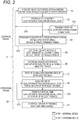
FIG. 2] FIG. 2 is a flowchart illustrating the operation of the BMI system. - [
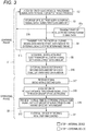
FIG. 3] Fig. 3 is a flowchart illustrating the operation of a BMI system of a second embodiment. - Hereinafter, embodiments will be described in detail with reference to the accompanying drawings.
-
FIG. 1 illustrates the functional configuration of aBMI system 100 of a first embodiment. TheBMI system 100 may include aninternal device 1 and anexternal device 200. Theinternal device 1 is configured so as to be used while being implanted in the living body 300 (specifically, the head). Theexternal device 200 is configured so as to be used while being placed outside theliving body 300. - The
internal device 1 includes a group ofN electrodes 2. In the following description, N is an integer of 2 or more. Each of the electrodes of the group ofN electrodes 2 is configured so as to be attached to a predetermined place in the brain of the livingbody 300, and acquire an electroencephalogram signal in the place. - The
internal device 1 may include adata acquisition section 3. Thedata acquisition section 3 may include an A/D converter. Electroencephalogram signals which are acquired through the group ofN electrodes 2 are analog signals. The A/D converter is configured so as to convert the analog signals to digital data at a predetermined sampling rate and a predetermined resolution. - A sampling rate corresponds to the frequency at which a digital signal is acquired. When the frequency is 1 kHz, 1,000 digital data are acquired from an analog signal for one second. A resolution corresponds to the number of values which may be taken by digital data. When the resolution is 16 bits, the range of values which may be taken by the amplitude of an input analog signal is divided into 16 bits, and one of 2 to the 16th power values is allocated to the amplitude of the input analog signal.
- The
internal device 1 may include acommunication section 5. Thecommunication section 5 is communicably connected to thedata acquisition section 3 and astorage section 4. Thecommunication section 5 is configured so as to be able to execute wireless communication with theexternal device 200. The communication rate of thecommunication section 5 is set to be lower than that which is necessary for transmitting in real time digital data that are acquired through the group ofN electrodes 2. - The
internal device 1 may include acontrol section 6. Thecontrol section 6 is communicably connected to thedata acquisition section 3 and thecommunication section 5. Thecontrol section 6 is configured so as to be able to control the operations of thedata acquisition section 3 and thecommunication section 5. - The
control section 6 is configured so as to cause thecommunication section 5 to wirelessly transmit all of digital data which correspond to electroencephalogram signals of the livingbody 300 that are detected through the group ofN electrodes 2, and which are acquired by thedata acquisition section 3, to theexternal device 200. - The
control section 6 is configured so as to, when thecommunication section 5 wirelessly receives a designation signal designating a group of M electrode(s) 2a, M being smaller than N, cause thecommunication section 5 to wirelessly transmit digital data which correspond to electroencephalogram signals of the livingbody 300 that are detected through the group of M electrode(s) 2a, and which are acquired by thedata acquisition section 3, to theexternal device 200 in real time. - The function of the
control section 6 is realized from software (computer programs) executed by a cooperation of a processor and memory which are communicably connected to each other. Examples of the processor are a CPU, an MPU, and a GPU. Examples of the memory are a ROM and a RAM. However, the function of thecontrol section 6 may be realized by a hardware resource such as an ASIC or an FPGA, or a combination of a hardware resource and software. - Next, a method for operating the thus configured
internal device 1 will be described with reference toFIG. 2 . - In a first time period, initially, a learning phase (S1) is performed. In the case where the living
body 300 performs an operation of grasping the hand, thereby causing theexternal device 200 to execute a predetermined operation, for example, the livingbody 300 is made to perform a learning operation. Specifically, the livingbody 300 is made to actually grasp the hand, or caused to think about an operation of grasping the hand. - When the living
body 300 performs a learning operation, an electroencephalogram corresponding to the learning operation is produced in the brain of the livingbody 300. The electroencephalogram is detected as N electroencephalogram signals by the group ofN electrodes 2. Thedata acquisition section 3 acquires digital data corresponding to the N electroencephalogram signals (S2). In the case where the learning operation is performed for one second, for example, digital data corresponding to electroencephalogram signals for three seconds in total including before and after one second are acquired. - Thereafter, the
control section 6 causes thecommunication section 5 to transmit all of the acquired digital data to the external device 200 (S4). The timing when the transmission is performed is a timing when the user inputs instructions to transmit, a predetermined time, a predetermined time interval, etc. The timing when the transmission is performed may be selected as a timing when real time monitoring of electroencephalogram signals is not necessary. Theexternal device 200 receives data which are transmitted from the internal device 1 (S5). - The data transmission from the
communication section 5 to theexternal device 200 is performed at a communication rate which is lower than the original transmission capability of thecommunication section 5, i.e., a value that is necessary for transmitting in real time data that are acquired through the group ofN electrodes 2, to theexternal device 200. In the case where 128-channel electroencephalogram signals that are acquired through a group of 128electrodes 2 are converted to digital data at a sampling rate of 1 kHz and a resolution of 16 bits, for example, a communication rate of about 2 Mbps is necessary (128 channels × 16 bits × 1k samples/sec = 2,048 kbits/sec = 2 Mbps) for transmitting the data to theexternal device 200 in real time. When the communication rate of thecommunication section 5 is 0.5 Mbps, digital data corresponding to electroencephalogram signals for three seconds which are acquired by thedata acquisition section 3 as described above are transmitted to theexternal device 200 with taking 12 seconds. - The
external device 200 may be identical with or different from a device which receives the signals transmitted from theinternal device 1, and which executes an operation based on the signals. For example, theexternal device 200 may be a device which receives the signals transmitted from theinternal device 1, and which transmits a control signal that causes another external device to execute the operation based on the transmitted signals. Alternatively, theexternal device 200 may be a device dedicated for performing an analysis which will be described later. - The data which are received by the
external device 200 are subjected to an analysis for reducing the amount of transmission data. In an actual BMI control, all of N electroencephalogram signals are not always required to have an accuracy which is similar to that in the learning process. The group ofN electrodes 2 are arranged at relatively narrow intervals, there are electrode group exhibiting a strong correlation, and also electrodes which have no involvement in the BMI control exist. In the analysis, the group of M electrode(s) 2a (seeFIG. 1 ) which have higher priority in the actual BMI control are specified (S6). M is an integer which is smaller than N. The value of M is adequately selected as a channel number corresponding to the data amount which is necessary in the BMI control. - In a second time period which is later than the first time period, an operating phase (S8) is performed. In the phase, the
external device 200 is actually BMI-controlled by the livingbody 300. When the livingbody 300 grasps the hand, for example, a predetermined operation corresponding to the operation is executed by theexternal device 200. - Initially, a signal designating the group of M electrode(s) 2a which are selected based on the above-described analysis is transmitted from the
external device 200. The signal is received by thecommunication section 5 of the internal device 1 (S7). When the signal is received by thecommunication section 5, thecontrol section 6 changes the setting so that thedata acquisition section 3 acquires only digital data corresponding to M electroencephalogram signals which are acquired through the group of M electrode(s) 2a (S9). The data acquisition section may acquire N electroencephalogram signals, but, when the acquisition is limited to the selected M signals, the power consumption can be reduced. - When the living
body 300 operates in the same manner as the above-described learning operation, an electroencephalogram corresponding to the learning operation is produced in the brain of the livingbody 300. In the operating phase (S8), therefore, thedata acquisition section 3 acquires digital data corresponding to electroencephalogram signals based on the above-described setting (S9). Thecontrol section 6 causes thecommunication section 5 to transmit in real time the digital data which are acquired by thedata acquisition section 3, to the external device 200 (S10). While repeating the operations of S9 and S10 (S12), theexternal device 200 executes in real time a predetermined operation based on the data which are transmitted from the communication section 5 (S11). - The group of M electrode(s) 2a are selected so that a desired BMI control can be executed. Moreover, the group of M electrode(s) 2a are selected so that the
communication section 5 can transmit in real time data corresponding to electroencephalogram signals which are acquired through the electrode group. Therefore, a real time BMI control of theexternal device 200 which corresponds to the operation of the livingbody 300 is realized. - According to the operating method in which the thus configured
internal device 1 is used, in the learning phase, data which are acquired through the group ofN electrodes 2, and the amount of which is relatively large are transmitted to theexternal device 200. In the phase, sure delivery of data as many as possible to theexternal device 200 takes precedence over the data transmission rate. Therefore, thecommunication section 5 is not required to have a high data transmission capability. - When many data are supplied to the
external device 200, the group of M electrode(s) 2a which has a priority in order to perform a desired BMI control can be correctly identified. Furthermore, the group of M electrode(s) 2a the number of which is smaller than N are identified so as to match with the data transmission capability of thecommunication section 5. In the operating phase, therefore, data corresponding to electroencephalogram signals which are acquired through the group of M electrode(s) 2a are transmitted in real time to theexternal device 200. This enables a desired BMI control to be executed without increasing the communication rate. - In order to perform the above-described learning phase, the system may include the
storage section 4 as illustrated inFIG. 1 . Thestorage section 4 is communicably connected to thedata acquisition section 3. Thestorage section 4 is configured so as to be able to store digital data which are acquired by thedata acquisition section 3. - The
control section 6 is communicably connected to thestorage section 4. As illustrated inFIG. 2 , prior to the above-described transmission (S4), thecontrol section 6 causes thestorage section 4 to store the digital data which are acquired by the data acquisition section 3 (S3). - As illustrated by the arrow of the broken line in
FIG. 2 , thecontrol section 6 may repeat as required steps S2 to S4 through step S3 (S13). Namely, the learning operation by the livingbody 300, the acquisition (S2) and storage (S3) of digital data corresponding to the N electroencephalogram signals which are acquired through the group ofN electrodes 2, and the transmission (S4) of the digital data to theexternal device 200 are repeated until desired electroencephalogram signal data that are necessary for the analysis in the learning phase are accumulated. According to the configuration, although the frequency of communications between thecommunication section 5 and theexternal device 200 is increased, the necessity of ensuring a large capacity in thestorage section 4 is reduced. Since the system includes the storage section, the digital data can be transmitted at an arbitrary timing. Therefore, the communication section is not required to have a high data transmission capability not only in the operating phase but also in the learning phase. Consequently, effects of reduction of the power consumption and suppression of heat generation are expected also in the learning phase. Moreover, the area of the communication section tends to be increased in accordance with the level of the data transmission capability. When the data transmission capability in both the learning and operating phases is suppressed to a low level, therefore, the area of the communication section can be reduced. - Prior to the above-described transmission (S4), alternatively, the
control section 6 may repeat as required the steps S2 and S3 (S14). Namely, the learning operation by the livingbody 300, and the acquisition (S2) and storage (S3) of digital data corresponding to the N electroencephalogram signals which are acquired through the group ofN electrodes 2 are repeated until desired electroencephalogram signal data that are necessary for the analysis in the learning phase are accumulated. Then, the data which are accumulated in thestorage section 4 are collectively transmitted to the external device 200 (S4). According to the configuration, the frequency of communications between thecommunication section 5 and theexternal device 200 can be reduced. Also in this operating method, the system includes the storage section, and therefore the communication section is not required to have a high data transmission capability even in the learning phase. Consequently, effects of reduction of the power consumption, suppression of heat generation, and reduction in size of the communication section are expected. - Alternatively, data of a group of arbitrary electrode(s) the number of which is smaller than N may be transmitted in real time to the
external device 200. In the case where data of one electrode are transmitted in real time to theexternal device 200, for example, the learning operation by the livingbody 300, the acquisition (S2) of digital data corresponding to one electroencephalogram signal which is acquired through one certain electrode, and the real time transmission (S4) of the digital data to theexternal device 200 are repeated until desired electroencephalogram signal data that are necessary for the analysis in the learning phase on the one certain electrode are accumulated. When this process is repeated on N electrodes, N electroencephalogram signal data that are necessary for the analysis in the learning phase can be acquired (S5). According to the configuration, although the same learning operation must be repeated many times, thestorage section 4 illustrated inFIG. 1 and step S3 illustrated inFIG. 2 are not necessary. When the number of electrode data which are transmitted at one time is increased in accordance with the transmission capability of thecommunication section 5, the time period of the learning phase can be shortened. - Moreover, a configuration where the
communication section 5 can transmit in real time data of all of the group ofN electrodes 2 to theexternal device 200 may be possible. Also in this case, thestorage section 4 illustrated inFIG. 1 and step S3 illustrated inFIG. 2 are not necessary. Namely, the learning operation by the livingbody 300, the acquisition (S2) of digital data corresponding to N electroencephalogram signals which are acquired through the group ofN electrodes 2, and the real time transmission (S4) of the digital data to theexternal device 200 are repeated until desired electroencephalogram signal data that are necessary for the analysis in the learning phase are accumulated. Although the power consumption in the learning phase cannot be reduced, an effect of reduction of the power consumption due to reduction of the number of electrode data to be transmitted can be obtained in the operating phase. - Prior to the above-described transmission (S4), moreover, the
control section 6 may cause thecommunication section 5 to transmit a part of data stored in thestorage section 4 to the external device 200 (S15). Such a process may be performed in order to check whether theinternal device 1 normally operates or not. When thecommunication section 5 receives instructions from theexternal device 200, such a process may be performed. - In the embodiment, the
control section 6 causes all of data corresponding to N electroencephalogram signals which are acquired in the learning phase by thedata acquisition section 3, to be transmitted to theexternal device 200. However, it is not always necessary to transmit all of data corresponding to N electroencephalogram signals. It is requested that the number of electroencephalogram signals which are transmitted in the learning phase is larger than that of electroencephalogram signals which are transmitted in the operating phase. - Next, an
internal device 1A of a second embodiment will be described with reference toFIG. 3 . The components identical or equivalent to those of theinternal device 1 of the first embodiment are denoted by the same reference numerals, and repeated description will be omitted. - As illustrated in
FIG. 1 , theinternal device 1A may include acontrol section 6A. Thecontrol section 6A is communicably connected to thedata acquisition section 3 and thecommunication section 5. Thecontrol section 6A is configured so as to be able to control the operations of thedata acquisition section 3 and thecommunication section 5. - The
control section 6A is configured so as to cause thecommunication section 5 to wirelessly transmit all of digital data which correspond to electroencephalogram signals of the livingbody 300 that are detected through the group ofN electrodes 2, and which are acquired by thedata acquisition section 3, to theexternal device 200. Namely, digital data having a first data amount are transmitted to theexternal device 200. - The
control section 6A is configured so as to, when thecommunication section 5 wirelessly receives a designation signal designating a second data amount which is smaller than the first data amount, cause thedata acquisition section 3 to acquire digital data which correspond to electroencephalogram signals of the livingbody 300 that are detected through the group ofN electrodes 2, and which have a second data amount. - Specifically, the
control section 6A lowers the data sampling rate, thereby reducing the data amount of digital data to be acquired. Alternatively, thecontrol section 6A lowers the data resolution, thereby reducing the data amount of digital data to be acquired. In order to reduce the amount of digital data to be acquired, thecontrol section 6A may lower both the sampling rate and the resolution. An example of the lowering of the resolution is lowering from 16 bits to 8 bits. The reductions of the sampling rate and the resolution may be performed through a hardware process or a software process. - The
control section 6A is configured so as to cause thecommunication section 5 to wirelessly transmit the digital data which are acquired as described above, to theexternal device 200 in real time. - The function of the
control section 6A is realized from software executed by a cooperation of a processor and memory which are communicably connected to each other. Examples of the processor are a CPU and an MPU. An example of the memory is a RAM. However, the function of thecontrol section 6 may be realized by hardware such as an ASIC or an FPGA, or a combination of hardware and software. - Next, a method for operating the thus configured
internal device 1A will be described with reference toFIG. 3 . The components identical to those of the operating method illustrated inFIG. 2 are denoted by the same reference numerals, and repeated description will be omitted. - In a first time period, the learning phase (S1) is performed. When the living
body 300 performs a learning operation, an electroencephalogram corresponding to the learning operation is produced in the brain of the livingbody 300. The electroencephalogram is detected as N electroencephalogram signals by the group ofN electrodes 2. Thedata acquisition section 3 acquires digital data which correspond to the N electroencephalogram signals, and which have the first data amount (S2). In the case where the learning operation is performed for one second, for example, digital data corresponding to electroencephalogram signals for three seconds in total including before and after one second are acquired. Thecontrol section 6A causes thestorage section 4 to store the digital data (S3). - Thereafter, the
control section 6A causes thecommunication section 5 to transmit all of the acquired digital data to the external device 200 (S4). The data transmission from thecommunication section 5 to theexternal device 200 is performed at a communication rate which is lower than the original transmission capability of thecommunication section 5, i.e., a value that is necessary for transmitting in real time data that are acquired through the group ofN electrodes 2, to theexternal device 200. Theexternal device 200 receives the data which are transmitted from the internal device 1 (S5). - The data which are received by the
external device 200 are subjected to an analysis for reducing the amount of transmission data. In the analysis, a second data amount at which a realistic BMI control can be performed without exceeding the real time data transmission capability of thecommunication section 5 is identified (S16). - In the second time period which is later than the first time period, the operating phase (S8) is performed. A signal designating the second data amount which is selected based on the above-described analysis is transmitted from the
external device 200. The signal is received by thecommunication section 5 of theinternal device 1A (S17). When the signal is received by thecommunication section 5, thecontrol section 6A changes the setting so that digital data having the second data amount can be transmitted. - For example, the
control section 6A lowers at least one of the data sampling rate and the resolution. In the case where the communication rate which is necessary for transmitting in real time digital data having the first data amount that are acquired at a first sampling rate and a first resolution through the group ofN electrodes 2 is 2 Mbps, and the real time data transmission capability of thecommunication section 5 is 0.5 Mbps, for example, thecontrol section 6A can reduce the amount of digital data which are acquired in the following manner, to the second data amount: - the first sampling rate is changed to a second sampling rate which is one quarter of the first sampling rate;
- the first resolution is changed to a second resolution which is one quarter of the first resolution; and
- the first sampling rate is changed to the second sampling rate which is one half of the first sampling rate, and the first resolution is changed to the second resolution which is one half of the first resolution (when the amount of the transmitted data is reduced to one quarter, the combination of the reduction amount of the sampling rate and that of the resolution can be adequately determined).
- Data which are acquired at the first resolution through a hardware process may be converted to those of the second resolution through a subsequent software process. The resolution and the sampling rate may be changed for each of the electrodes.
- When the living
body 300 operates in the same manner as the above-described learning operation, an electroencephalogram corresponding to the operation is produced in the brain of the livingbody 300. Thedata acquisition section 3 acquires digital data having the second data amount through the group of N electrodes 2 (S18). Thecontrol section 6A causes thecommunication section 5 to transmit in real time the digital data which are acquired by thedata acquisition section 3, to the external device 200 (S19). While repeating the operations of S18 and S19 (S12), theexternal device 200 executes in real time a predetermined operation based on the data which are transmitted from the communication section 5 (S11). - The second data amount is selected so that a desired BMI control can be executed. Moreover, the second data amount is selected so that the
communication section 5 can transmit in real time the acquired digital data. Therefore, a real time BMI control of theexternal device 200 which corresponds to the operation of the livingbody 300 is realized. - According to the operating method in which the thus configured
internal device 1A is used, in the learning phase, data which are acquired through the group ofN electrodes 2, and which have the first date amount that is relatively large are once stored in thestorage section 4. The stored data are then transmitted to theexternal device 200. In the phase, sure delivery of data as many as possible to theexternal device 200 takes precedence over the data transmission rate. Therefore, thecommunication section 5 is not required to have a high data transmission capability. - The operating method in the first embodiment in which the
storage section 4 is not required in learning phase can be applied also to the second embodiment. - When many data are supplied to the
external device 200, the second data amount which is necessary in order to perform a desired BMI control can be correctly identified. Furthermore, the second data amount is identified so as to match with the data transmission capability of thecommunication section 5. In the operating phase, therefore, data corresponding to electroencephalogram signals which are acquired through the group ofN electrodes 2 are transmitted in real time as they are to theexternal device 200. This enables a desired BMI control to be executed without increasing the communication rate. - In the embodiment, the
control section 6A causes all of digital data which are acquired in the learning phase by thedata acquisition section 3, and which have the first data amount, to be transmitted to theexternal device 200. However, it is not always necessarily to transmit all of data having the first data amount. It is requested that the amount of data which are transmitted in the learning phase is larger than that of data which are transmitted in the operating phase. - The above-described embodiments are mere examples for facilitating understanding of the disclosure. The configurations of the embodiments may be adequately changed or improved without departing from the spirit of the presently disclosed subject matter. When the first and second embodiments are combined with each other, for example, the sampling rate and resolution of data which are acquired by a group of M electrode(s), M being smaller than N, may be lowered, and the amount of transmitted data may be further reduced.
- The disclosure of Japanese Patent Application No.
2017-023413 filed February 10, 2017
Claims (12)
- An internal device of a brain-machine interface system, the internal device adapted to be implanted in a living body, the internal device comprising:a communication section which wirelessly communicates with an external device; anda control section which controls the communication section, whereinthe control section causes:the communication section to transmit data corresponding to electroencephalogram signals of the living body which are detected through a group of N (N is 2 or more) electrodes, to the external device; and,when, after the transmission is performed, the communication section receives a designation signal designating a group of M electrode(s), M being smaller than N, the communication section to transmit data corresponding to electroencephalogram signals of the living body which are detected through the group of M electrode(s), to the external device in real time.
- The internal device according to claim 1, further comprising:a storage section, whereinprior to the transmission of the data corresponding to electroencephalogram signals of the living body which are detected through the group of N electrodes, the control section causes the storage section to repeatedly store the data corresponding to electroencephalogram signals of the living body which are detected through the group of N electrodes.
- The internal device according to claim 1 or 2, wherein
prior to the transmission of the data corresponding to electroencephalogram signals of the living body which are detected through the group of N electrodes, the control section causes the communication section to transmit a part of the data to the external device. - A method for controlling an internal device of a brain-machine interface system, the internal device adapted to be implanted in a living body, the method comprising:wirelessly transmitting data corresponding to electroencephalogram signals of the living body which are detected through a group of N (N is 2 or more) electrodes to an external device;after the wireless transmission is performed, wirelessly receiving a designation signal designating a group of M electrode(s), M being smaller than N; andwirelessly transmitting data corresponding to electroencephalogram signals of the living body which are detected through the group of M electrode(s) to the external device in real time.
- The controlling method according to claim 4, wherein
the internal device further includes a storage section, and,
the method further comprises: prior to the transmission of the data corresponding to electroencephalogram signals of the living body which are detected through the group of N electrodes, repeatedly storing in the storage section the data corresponding to electroencephalogram signals of the living body which are detected through the group of N electrodes. - The controlling method according to claim 4 or 5, further comprising:
prior to the transmission of the data corresponding to electroencephalogram signals of the living body which are detected through the group of N electrodes, wirelessly transmitting a part of the data to the external device. - An internal device of a brain-machine interface system, the internal device adapted to be implanted in a living body, the internal device comprising:a data acquisition section;a communication section which wirelessly communicates with an external device; anda control section which controls the communication section, whereinthe control section causes:the data acquisition section to acquire first data corresponding to electroencephalogram signals of the living body which are detected through N (N is 2 or more) electrodes, the first data having a first data amount;the communication section to transmit the first data to the external device;when, after the transmission is performed, the communication section receives a designation signal designating a second data amount which is smaller than the first data amount, the data acquisition section to acquire second data corresponding to electroencephalogram signals of the living body which are detected through the N electrodes, the second data having the second data amount; andthe communication section to transmit the second data to the external device in real time.
- The internal device according to claim 7, wherein
the data acquisition section acquires the first data by sampling the electroencephalogram signals at a first sampling rate, and acquires the second data by sampling the electroencephalogram signals at a second sampling rate which is lower than the first sampling rate. - The internal device according to claim 7 or 8, wherein
the data acquisition section acquires the first data by A/D-converting the electroencephalogram signals at a first resolution, and acquires the second data by A/D-converting the electroencephalogram signals at a second resolution which is lower than the first resolution. - A method for controlling an internal device of a brain-machine interface system, the internal device adapted to be implanted in a living body, the method comprising:acquiring first data corresponding to electroencephalogram signals of the living body which are detected through a group of N (N is 2 or more) electrodes, the first data having a first data amount;wirelessly transmitting the first data to an external device;after the wireless transmission is performed, wirelessly receiving a designation signal designating a second data amount rather than the first data amount;acquiring second data corresponding to electroencephalogram signals of the living body which are detected through the group of N electrodes, the second data having the second data amount; andwirelessly transmitting the second data to the external device in real time.
- The controlling method according to claim 10, wherein
the first data are acquired by sampling the electroencephalogram signals at a first sampling rate, and the second data are acquired by sampling the electroencephalogram signals at a second sampling rate which is lower than the first sampling rate. - The controlling method according to claim 10 or 11, wherein
the first data are acquired by A/D-converting the electroencephalogram signals at a first resolution, and the second data are acquired by A/D-converting the electroencephalogram signals at a second resolution which is lower than the first resolution.
Applications Claiming Priority (2)
| Application Number | Priority Date | Filing Date | Title |
|---|---|---|---|
| JP2017023413 | 2017-02-10 | ||
| PCT/JP2018/004561 WO2018147407A1 (en) | 2017-02-10 | 2018-02-09 | Brain-machine interface system capable of changing amount of communication data from internal device, and control method therefor |
Publications (3)
| Publication Number | Publication Date |
|---|---|
| EP3582069A1 true EP3582069A1 (en) | 2019-12-18 |
| EP3582069A4 EP3582069A4 (en) | 2020-11-25 |
| EP3582069B1 EP3582069B1 (en) | 2025-10-22 |
Family
ID=63107546
Family Applications (1)
| Application Number | Title | Priority Date | Filing Date |
|---|---|---|---|
| EP18751161.3A Active EP3582069B1 (en) | 2017-02-10 | 2018-02-09 | Brain-machine interface system capable of changing amount of communication data from internal device, and control method therefor |
Country Status (4)
| Country | Link |
|---|---|
| US (1) | US11779278B2 (en) |
| EP (1) | EP3582069B1 (en) |
| JP (1) | JP7186947B2 (en) |
| WO (1) | WO2018147407A1 (en) |
Families Citing this family (4)
| Publication number | Priority date | Publication date | Assignee | Title |
|---|---|---|---|---|
| JP7054967B2 (en) * | 2019-12-26 | 2022-04-15 | 国立大学法人大阪大学 | Resistance device, integrated circuit device, implantable device, and correction coefficient determination method |
| EP4111294A4 (en) | 2020-04-01 | 2024-03-20 | Synchron Australia Pty Ltd | SYSTEMS AND METHODS FOR CONTROLLING A DEVICE USING CHANGES DETECTED IN A SIGNAL INHERENT TO THE NEURAL SYSTEM |
| CN113115474B (en) * | 2021-03-19 | 2022-07-19 | 苏州景昱医疗器械有限公司 | Method and equipment for transmitting electroencephalogram signals while charging |
| JP6991622B1 (en) | 2021-04-21 | 2022-01-14 | 株式会社メルティンMmi | Methods, systems, and electrode structures for acquiring electrical signals from multiple nerves in a living body, and methods for manufacturing the electrode structures. |
Family Cites Families (13)
| Publication number | Priority date | Publication date | Assignee | Title |
|---|---|---|---|---|
| US6230049B1 (en) * | 1999-08-13 | 2001-05-08 | Neuro Pace, Inc. | Integrated system for EEG monitoring and electrical stimulation with a multiplicity of electrodes |
| US20060058627A1 (en) | 2004-08-13 | 2006-03-16 | Flaherty J C | Biological interface systems with wireless connection and related methods |
| US8560041B2 (en) | 2004-10-04 | 2013-10-15 | Braingate Co., Llc | Biological interface system |
| US8073545B2 (en) * | 2006-07-21 | 2011-12-06 | Neuropace, Inc. | Treatment and warning of recurring therapy and other events using an implantable device |
| WO2008057365A2 (en) * | 2006-11-02 | 2008-05-15 | Caplan Abraham H | Epileptic event detection systems |
| CN101835420A (en) * | 2007-08-23 | 2010-09-15 | 麻省理工学院 | Method and apparatus for reducing the number of channels in an EEG-based seizure detector |
| AU2009204001A1 (en) | 2008-01-11 | 2009-07-16 | Oregon Health & Science University | Rapid serial presentation communication systems and methods |
| JP5746206B2 (en) | 2010-11-09 | 2015-07-08 | 国立大学法人大阪大学 | Implantable device |
| US10617361B2 (en) | 2010-11-09 | 2020-04-14 | Osaka University | Casing of implantable device and implantable device, method for manufacturing casing of implantable device, and method for supporting treatment using implantable device |
| US9060671B2 (en) | 2012-08-17 | 2015-06-23 | The Nielsen Company (Us), Llc | Systems and methods to gather and analyze electroencephalographic data |
| GB201401613D0 (en) | 2014-01-30 | 2014-03-19 | Univ Leicester | System for a brain-computer interface |
| US10758174B2 (en) * | 2014-04-25 | 2020-09-01 | The General Hospital Corporation | Method for cross-diagnostic identification and treatment of neurologic features underpinning mental and emotional disorders |
| JP2017023413A (en) | 2015-07-22 | 2017-02-02 | ファミリーイナダ株式会社 | Massage machine |
-
2018
- 2018-02-09 EP EP18751161.3A patent/EP3582069B1/en active Active
- 2018-02-09 US US16/484,922 patent/US11779278B2/en active Active
- 2018-02-09 JP JP2018567508A patent/JP7186947B2/en active Active
- 2018-02-09 WO PCT/JP2018/004561 patent/WO2018147407A1/en not_active Ceased
Also Published As
| Publication number | Publication date |
|---|---|
| WO2018147407A1 (en) | 2018-08-16 |
| US11779278B2 (en) | 2023-10-10 |
| JPWO2018147407A1 (en) | 2020-02-13 |
| EP3582069B1 (en) | 2025-10-22 |
| JP7186947B2 (en) | 2022-12-12 |
| EP3582069A4 (en) | 2020-11-25 |
| US20200054284A1 (en) | 2020-02-20 |
Similar Documents
| Publication | Publication Date | Title |
|---|---|---|
| US11779278B2 (en) | Brain-machine interface system capable of changing amount of communication data from internal device, and control method therefor | |
| Rizk et al. | A single-chip signal processing and telemetry engine for an implantable 96-channel neural data acquisition system | |
| CN101742959A (en) | Protocol converter for wireless patient monitoring | |
| MX2011002097A (en) | Method and system for communication between wireless devices. | |
| JP2020517334A (en) | System and method for using a novel ECG screening algorithm for reduced left ventricular ejection fraction | |
| KR20080057533A (en) | Method and device for driving terminal using EEG | |
| CN103784125B (en) | For the one-to-many data acquisition means of communication of physiological compensation effects | |
| KR102176763B1 (en) | Adc sampling and resource usage optimization with active variable sampling and active variable phase control | |
| EP3696649A1 (en) | Electronic device and control method therefor | |
| CN108512629B (en) | Electrocardio monitoring data sending, receiving and controlling method and system | |
| CN105578239A (en) | A TV Control System Based on Brain-Computer Interface Technology | |
| KR101270634B1 (en) | Method for controlling electroencephalography analyzer and electroencephalography analyzing system | |
| US12494202B2 (en) | Brain signal-based user assisting method and apparatus | |
| Frigo et al. | IEEE 802.15. 6 compliant WBSN: a case study | |
| EP4311364A1 (en) | Method for transmitting brain electrical signal, and device | |
| AU2019205982A1 (en) | Physician related selective data compression | |
| CN117376998A (en) | Channel switching method, system, related equipment and storage medium | |
| KR101916418B1 (en) | Method and apparatus for reducing power consumption of receiver | |
| US20130274626A1 (en) | Measuring method for synchronizing bio-signals with stimulations | |
| KR101890546B1 (en) | Diagnostic device for low back pain -based electromyogram | |
| JP7791603B2 (en) | Stimulation system, implant device, control device, control method for control device, and program | |
| CN112763778A (en) | Waveform display method, device, equipment and storage medium | |
| JP2021078889A5 (en) | ||
| AU2006211808A1 (en) | Method and apparatus for monitoring a sedated patient | |
| CN103211652B (en) | Biostimulation signal measuring method |
Legal Events
| Date | Code | Title | Description |
|---|---|---|---|
| STAA | Information on the status of an ep patent application or granted ep patent |
Free format text: STATUS: THE INTERNATIONAL PUBLICATION HAS BEEN MADE |
|
| PUAI | Public reference made under article 153(3) epc to a published international application that has entered the european phase |
Free format text: ORIGINAL CODE: 0009012 |
|
| STAA | Information on the status of an ep patent application or granted ep patent |
Free format text: STATUS: REQUEST FOR EXAMINATION WAS MADE |
|
| 17P | Request for examination filed |
Effective date: 20190809 |
|
| AK | Designated contracting states |
Kind code of ref document: A1 Designated state(s): AL AT BE BG CH CY CZ DE DK EE ES FI FR GB GR HR HU IE IS IT LI LT LU LV MC MK MT NL NO PL PT RO RS SE SI SK SM TR |
|
| AX | Request for extension of the european patent |
Extension state: BA ME |
|
| DAV | Request for validation of the european patent (deleted) | ||
| DAX | Request for extension of the european patent (deleted) | ||
| A4 | Supplementary search report drawn up and despatched |
Effective date: 20201023 |
|
| RIC1 | Information provided on ipc code assigned before grant |
Ipc: A61F 2/72 20060101ALI20201020BHEP Ipc: A61B 5/0484 20060101ALI20201020BHEP Ipc: A61B 5/04 20060101ALI20201020BHEP Ipc: A61B 5/0476 20060101ALI20201020BHEP Ipc: G06F 3/01 20060101AFI20201020BHEP |
|
| STAA | Information on the status of an ep patent application or granted ep patent |
Free format text: STATUS: EXAMINATION IS IN PROGRESS |
|
| 17Q | First examination report despatched |
Effective date: 20220321 |
|
| GRAP | Despatch of communication of intention to grant a patent |
Free format text: ORIGINAL CODE: EPIDOSNIGR1 |
|
| STAA | Information on the status of an ep patent application or granted ep patent |
Free format text: STATUS: GRANT OF PATENT IS INTENDED |
|
| RIC1 | Information provided on ipc code assigned before grant |
Ipc: A61B 5/30 20210101ALI20250422BHEP Ipc: A61B 5/291 20210101ALI20250422BHEP Ipc: A61B 5/00 20060101ALI20250422BHEP Ipc: A61F 2/72 20060101ALI20250422BHEP Ipc: G06F 3/01 20060101AFI20250422BHEP |
|
| INTG | Intention to grant announced |
Effective date: 20250514 |
|
| GRAS | Grant fee paid |
Free format text: ORIGINAL CODE: EPIDOSNIGR3 |
|
| GRAA | (expected) grant |
Free format text: ORIGINAL CODE: 0009210 |
|
| STAA | Information on the status of an ep patent application or granted ep patent |
Free format text: STATUS: THE PATENT HAS BEEN GRANTED |
|
| AK | Designated contracting states |
Kind code of ref document: B1 Designated state(s): AL AT BE BG CH CY CZ DE DK EE ES FI FR GB GR HR HU IE IS IT LI LT LU LV MC MK MT NL NO PL PT RO RS SE SI SK SM TR |
|
| RAP3 | Party data changed (applicant data changed or rights of an application transferred) |
Owner name: NIHON KOHDEN CORPORATION Owner name: OSAKA UNIVERSITY Owner name: NATIONAL INSTITUTE OF INFORMATION ANDCOMMUNICATIONS TECHNOLOGY Owner name: SPCHANGE, LLC |
|
| REG | Reference to a national code |
Ref country code: CH Ref legal event code: F10 Free format text: ST27 STATUS EVENT CODE: U-0-0-F10-F00 (AS PROVIDED BY THE NATIONAL OFFICE) Effective date: 20251022 Ref country code: GB Ref legal event code: FG4D |
|
| REG | Reference to a national code |
Ref country code: DE Ref legal event code: R096 Ref document number: 602018086543 Country of ref document: DE |
|
| REG | Reference to a national code |
Ref country code: IE Ref legal event code: FG4D |
|
| REG | Reference to a national code |
Ref country code: NL Ref legal event code: MP Effective date: 20251022 |
|
| PG25 | Lapsed in a contracting state [announced via postgrant information from national office to epo] |
Ref country code: NL Free format text: LAPSE BECAUSE OF FAILURE TO SUBMIT A TRANSLATION OF THE DESCRIPTION OR TO PAY THE FEE WITHIN THE PRESCRIBED TIME-LIMIT Effective date: 20251022 |
|
| PG25 | Lapsed in a contracting state [announced via postgrant information from national office to epo] |
Ref country code: ES Free format text: LAPSE BECAUSE OF FAILURE TO SUBMIT A TRANSLATION OF THE DESCRIPTION OR TO PAY THE FEE WITHIN THE PRESCRIBED TIME-LIMIT Effective date: 20251022 |
|
| REG | Reference to a national code |
Ref country code: LT Ref legal event code: MG9D |
|
| PG25 | Lapsed in a contracting state [announced via postgrant information from national office to epo] |
Ref country code: NO Free format text: LAPSE BECAUSE OF FAILURE TO SUBMIT A TRANSLATION OF THE DESCRIPTION OR TO PAY THE FEE WITHIN THE PRESCRIBED TIME-LIMIT Effective date: 20260122 |
|
| PG25 | Lapsed in a contracting state [announced via postgrant information from national office to epo] |
Ref country code: AT Free format text: LAPSE BECAUSE OF FAILURE TO SUBMIT A TRANSLATION OF THE DESCRIPTION OR TO PAY THE FEE WITHIN THE PRESCRIBED TIME-LIMIT Effective date: 20251022 Ref country code: HR Free format text: LAPSE BECAUSE OF FAILURE TO SUBMIT A TRANSLATION OF THE DESCRIPTION OR TO PAY THE FEE WITHIN THE PRESCRIBED TIME-LIMIT Effective date: 20251022 Ref country code: FI Free format text: LAPSE BECAUSE OF FAILURE TO SUBMIT A TRANSLATION OF THE DESCRIPTION OR TO PAY THE FEE WITHIN THE PRESCRIBED TIME-LIMIT Effective date: 20251022 |
|
| REG | Reference to a national code |
Ref country code: AT Ref legal event code: MK05 Ref document number: 1849695 Country of ref document: AT Kind code of ref document: T Effective date: 20251022 |
|
| PG25 | Lapsed in a contracting state [announced via postgrant information from national office to epo] |
Ref country code: RS Free format text: LAPSE BECAUSE OF FAILURE TO SUBMIT A TRANSLATION OF THE DESCRIPTION OR TO PAY THE FEE WITHIN THE PRESCRIBED TIME-LIMIT Effective date: 20260122 |
|
| PG25 | Lapsed in a contracting state [announced via postgrant information from national office to epo] |
Ref country code: IS Free format text: LAPSE BECAUSE OF FAILURE TO SUBMIT A TRANSLATION OF THE DESCRIPTION OR TO PAY THE FEE WITHIN THE PRESCRIBED TIME-LIMIT Effective date: 20260222 |
|
| PGFP | Annual fee paid to national office [announced via postgrant information from national office to epo] |
Ref country code: FR Payment date: 20260121 Year of fee payment: 9 |
|
| PG25 | Lapsed in a contracting state [announced via postgrant information from national office to epo] |
Ref country code: PT Free format text: LAPSE BECAUSE OF FAILURE TO SUBMIT A TRANSLATION OF THE DESCRIPTION OR TO PAY THE FEE WITHIN THE PRESCRIBED TIME-LIMIT Effective date: 20260223 |
|
| PG25 | Lapsed in a contracting state [announced via postgrant information from national office to epo] |
Ref country code: PL Free format text: LAPSE BECAUSE OF FAILURE TO SUBMIT A TRANSLATION OF THE DESCRIPTION OR TO PAY THE FEE WITHIN THE PRESCRIBED TIME-LIMIT Effective date: 20251022 |
|
| PG25 | Lapsed in a contracting state [announced via postgrant information from national office to epo] |
Ref country code: LV Free format text: LAPSE BECAUSE OF FAILURE TO SUBMIT A TRANSLATION OF THE DESCRIPTION OR TO PAY THE FEE WITHIN THE PRESCRIBED TIME-LIMIT Effective date: 20251022 |
|
| PG25 | Lapsed in a contracting state [announced via postgrant information from national office to epo] |
Ref country code: BG Free format text: LAPSE BECAUSE OF FAILURE TO SUBMIT A TRANSLATION OF THE DESCRIPTION OR TO PAY THE FEE WITHIN THE PRESCRIBED TIME-LIMIT Effective date: 20251022 |