EP3581826A1 - Damping for a haptic actuator - Google Patents
Damping for a haptic actuator Download PDFInfo
- Publication number
- EP3581826A1 EP3581826A1 EP19180361.8A EP19180361A EP3581826A1 EP 3581826 A1 EP3581826 A1 EP 3581826A1 EP 19180361 A EP19180361 A EP 19180361A EP 3581826 A1 EP3581826 A1 EP 3581826A1
- Authority
- EP
- European Patent Office
- Prior art keywords
- haptic
- mass
- damping
- actuator
- output device
- Prior art date
- Legal status (The legal status is an assumption and is not a legal conclusion. Google has not performed a legal analysis and makes no representation as to the accuracy of the status listed.)
- Withdrawn
Links
Images



Classifications
-
- G—PHYSICS
- G08—SIGNALLING
- G08B—SIGNALLING SYSTEMS, e.g. PERSONAL CALLING SYSTEMS; ORDER TELEGRAPHS; ALARM SYSTEMS
- G08B6/00—Tactile signalling systems, e.g. tactile personal calling systems
-
- F—MECHANICAL ENGINEERING; LIGHTING; HEATING; WEAPONS; BLASTING
- F16—ENGINEERING ELEMENTS AND UNITS; GENERAL MEASURES FOR PRODUCING AND MAINTAINING EFFECTIVE FUNCTIONING OF MACHINES OR INSTALLATIONS; THERMAL INSULATION IN GENERAL
- F16F—SPRINGS; SHOCK-ABSORBERS; MEANS FOR DAMPING VIBRATION
- F16F15/00—Suppression of vibrations in systems; Means or arrangements for avoiding or reducing out-of-balance forces, e.g. due to motion
- F16F15/005—Suppression of vibrations in systems; Means or arrangements for avoiding or reducing out-of-balance forces, e.g. due to motion using electro- or magnetostrictive actuation means
-
- F—MECHANICAL ENGINEERING; LIGHTING; HEATING; WEAPONS; BLASTING
- F16—ENGINEERING ELEMENTS AND UNITS; GENERAL MEASURES FOR PRODUCING AND MAINTAINING EFFECTIVE FUNCTIONING OF MACHINES OR INSTALLATIONS; THERMAL INSULATION IN GENERAL
- F16F—SPRINGS; SHOCK-ABSORBERS; MEANS FOR DAMPING VIBRATION
- F16F15/00—Suppression of vibrations in systems; Means or arrangements for avoiding or reducing out-of-balance forces, e.g. due to motion
- F16F15/02—Suppression of vibrations of non-rotating, e.g. reciprocating systems; Suppression of vibrations of rotating systems by use of members not moving with the rotating systems
- F16F15/023—Suppression of vibrations of non-rotating, e.g. reciprocating systems; Suppression of vibrations of rotating systems by use of members not moving with the rotating systems using fluid means
- F16F15/027—Suppression of vibrations of non-rotating, e.g. reciprocating systems; Suppression of vibrations of rotating systems by use of members not moving with the rotating systems using fluid means comprising control arrangements
-
- G—PHYSICS
- G06—COMPUTING OR CALCULATING; COUNTING
- G06F—ELECTRIC DIGITAL DATA PROCESSING
- G06F3/00—Input arrangements for transferring data to be processed into a form capable of being handled by the computer; Output arrangements for transferring data from processing unit to output unit, e.g. interface arrangements
- G06F3/01—Input arrangements or combined input and output arrangements for interaction between user and computer
- G06F3/016—Input arrangements with force or tactile feedback as computer generated output to the user
-
- H—ELECTRICITY
- H10—SEMICONDUCTOR DEVICES; ELECTRIC SOLID-STATE DEVICES NOT OTHERWISE PROVIDED FOR
- H10N—ELECTRIC SOLID-STATE DEVICES NOT OTHERWISE PROVIDED FOR
- H10N30/00—Piezoelectric or electrostrictive devices
- H10N30/20—Piezoelectric or electrostrictive devices with electrical input and mechanical output, e.g. functioning as actuators or vibrators
-
- F—MECHANICAL ENGINEERING; LIGHTING; HEATING; WEAPONS; BLASTING
- F16—ENGINEERING ELEMENTS AND UNITS; GENERAL MEASURES FOR PRODUCING AND MAINTAINING EFFECTIVE FUNCTIONING OF MACHINES OR INSTALLATIONS; THERMAL INSULATION IN GENERAL
- F16F—SPRINGS; SHOCK-ABSORBERS; MEANS FOR DAMPING VIBRATION
- F16F2224/00—Materials; Material properties
- F16F2224/04—Fluids
- F16F2224/045—Fluids magnetorheological
-
- F—MECHANICAL ENGINEERING; LIGHTING; HEATING; WEAPONS; BLASTING
- F16—ENGINEERING ELEMENTS AND UNITS; GENERAL MEASURES FOR PRODUCING AND MAINTAINING EFFECTIVE FUNCTIONING OF MACHINES OR INSTALLATIONS; THERMAL INSULATION IN GENERAL
- F16F—SPRINGS; SHOCK-ABSORBERS; MEANS FOR DAMPING VIBRATION
- F16F2230/00—Purpose; Design features
- F16F2230/22—Pumps
Definitions
- This patent document relates to haptic actuators, and more particularly to the damping of haptic actuators.
- Haptic effects are used to enhance the interaction of an individual with an electronic device. Haptic effects enable the user to experience a touch or tactile sensation, which is typically generated by a haptic output device.
- a haptic actuator that drives or causes a mass to move back and forth to create a vibration.
- a haptic signal is applied to a haptic actuator causing it to move or vibrate.
- the haptic actuator causes the mass to move and generate a vibration.
- the haptic signal is ended and a braking pulse or signal is then applied to the haptic actuator.
- the braking pulse or signal is out of phase, typically a 180° out of phase, from the haptic signal. It urges the haptic actuator to reverse direction, which causes movement of the actuator and haptic mass to stop.
- a problem with such haptic output devices is that the mass can have a tail vibration in which the haptic actuator continues vibrating or moving for a period of time after the event associated with the haptic event ends.
- the haptic effect lasts longer than desired.
- such braking techniques are not effective for generating haptic effects having a very short duration.
- a haptic output device is positioned within a device housing.
- the haptic output device has a haptic actuator and a haptic mass, the haptic mass being movable relative to the housing.
- a damper is positioned within the device housing.
- a controller is programmed to generate and deliver a haptic signal to the haptic actuator at a first time, and to generate and deliver a damping signal to the damper at a second time, the second time occurring after the first time.
- Another aspect of this patent document is directed to a method of damping haptic vibrations.
- the method comprises moving a haptic mass, the haptic mass position in a housing; vibrating the housing in response to moving the haptic mass; damping movement of the haptic mass after a period of time; and substantially eliminating vibration of the housing in response to damping movement of the haptic mass.
- this patent document relates to damping movement of a haptic actuator to reduce or eliminate movement or vibration of a haptic output device. Damping can be reducing or completely stopping movement of the actuator.
- An advantage of the embodiments disclosed herein is that they enable damping the haptic actuator very quickly so that very short haptic effects can be generated.
- Application for which very short haptic effects can be useful include simulating or emulating a button or switch that has a very short tactile sensation such as a click. Another example is the tactile sensation to simulate the bounce of a ball.
- the damping can be gradually increased or decreased to provide a sense of linear motion, rotation, acceleration, deceleration, or going up or down a hill.
- the damping can vary as the electronic device senses gestures either through a user interface such as a touch screen or free space gestures.
- the damping can also vary as the electronic device moves through the six degrees of freedom (6DOF) of: (1) up and down; (2) left and right; (3) forward and backward; (4) yaw (rotation or movement around a vertical axis); (5) pitch (rotation or movement around a horizontal axis); and (6) roll (rotation or movement around the orthogonal horizontal axis).
- the damping can vary by increasing the damping, decreasing the damping, stepping up or down the damping, modulating the damping, oscillating the damping, other changes in the length or amplitude of the damping, and combinations thereof. This type of control over damping gives a haptic developer much greater flexibility when designing haptic effects.
- the haptic actuator can be any actuator that has mechanical movement including haptic actuators that control movement of a haptic mass.
- haptic actuators include mechanisms such as motors; linear actuators such as solenoids; magnetic or electromagnetic mechanisms; and smart materials such as shape memory alloys, piezoelectric materials, electroactive polymers, and materials containing smart fluids.
- the haptic actuators disclosed herein and used with damping mechanisms include piezoelectric actuators that have a piezoelectric transducer that drives cymbals to amplify vibration of the piezoelectric transducer and Linear Resonant Actuator (LRA) in which a mass attached to a spring is driven back and forth.
- LRA Linear Resonant Actuator
- damping mechanisms such as those disclosed herein can be used with any type of haptic actuator that produces mechanical movement.
- Other examples include other types of piezoelectric actuators, other types of LRA's, solenoid resonant actuators (SRA), electromagnetic actuators, motors or smart materials that drive an Eccentric Rotating Mass (ERM), smart material materials (such as electro-active polymers or shape memory alloys) that move when exposed to or stimulated by external forces, voice coil actuators, electro-active polymer (EAP) actuators, moving magnet actuators, smart gels, deformable surfaces, or any other haptic output device or collection of components that have mechanical movement to cause a haptic output device to vibrate.
- SRA solenoid resonant actuators
- EEM Eccentric Rotating Mass
- EAP electro-active polymer
- moving magnet actuators smart gels, deformable surfaces, or any other haptic output device or collection of components that have mechanical movement to cause a haptic output device to vibrate.
- haptic actuators and damping mechanisms disclosed herein can be used with any electronic device in which it is desirable to have haptic effects. Examples include cell phones, smart phones, game controllers, tablet computers, calculators, game counsels, haptically-enabled wearable devices, medical devices, medical monitors, safety equipment, GPS devices, automobile components, glasses, helmets, wristwatches, smart watches, and any other electronic device.
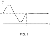
- Figure 1 is a chart that plots movement of a haptic actuator before and after damping.
- the chart plots the amplitude, a , of the haptic actuator as it moves versus time. Damping begins at time t 1 .
- the amplitude value of 0 along the amplitude axis of the chart is the position of the actuator at which it is in its natural or resting state.
- the embodiments disclosed herein can be configured and programmed so that the period between a time of zero (0) and time t 1 has any desired or determined value. In one possible example, the time t 1 is 15 microseconds.
- movement of the haptic actuator can be dampened to reduce, but not entirely eliminate movement.
- movement of the haptic actuator is controlled to increase and decrease damping of the haptic actuator at different points in time to create different haptic effects.
- FIGS 2-4 illustrate a haptic actuator 100 having a piezoelectric transducer 114 positioned between opposing cymbals 102a and 102b.
- Each symbol has an edge 104, a bow 108, and a taper 106 leading between the edge 104 and the bow 108.
- a cavity 112 is defined between each cymbal 102a and 102b and the piezoelectric transducer 114.
- Each cymbal 102a and 102b also has a port 110 in its bow 108 that is in fluid communication with the cavity 112. In operation, when an electrical or haptic signal is applied to the piezoelectric transducer 114, it will move or flex causing it to vibrate.
- the cymbals 102a and 102b amplify the vibrations and can be made of any suitable material such as a metal.
- An example of the haptic actuator 100 illustrated in Figure 2 is commercially available from TDK U.S.A. Corporation of Uniondale, NY under the commercial name PowerHapTM.
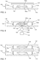
- Figure 5 illustrates a haptic output device 116 having a fixed base 118, haptic mass 120, springs 122a and 122b, a damping mechanism 124, and the haptic actuator 100.
- the fixed base 118 is in a fixed or unmovable position relative to other components of the haptic output device 116 and in a fixed position relative to the electronic device in which the haptic output device 116 is mounted.
- the haptic mass 120 is operably connected to the fixed base 118 by springs 122a and 122b.
- the haptic actuator 100 is positioned between the fixed base 118 and moving mass 120. Cymbal 102b is oriented toward and operably connected to the fixed base 118, and cymbal 102a is oriented towards and operably connected to the moving mass 120.
- the haptic output device 116 is mounted in an electronic device.
- the damping mechanism 124 is positioned proximal to the moving mass 120.
- the damping mechanism 124 is positioned very close to, but not in contact with, the moving mass 120.
- the electromagnetic damper 124 can have other positions relative to the moving mass 120 so long as it is able to control movement of the moving mass 120 and of the haptic actuator 100.
- the damping mechanism 124 includes electrical coils to form an electromagnetic damping mechanism.
- the moving mass 120 includes a ferrous material that is attracted to or repelled by a magnetic field.
- the piezoelectric transducer 114 of the haptic actuator 100 receives an electrical signal or haptic drive signal, which causes it to vibrate.
- Cymbals 102a and 102b amplify the vibration and cause the haptic mass 120 to move relative to the fixed base 118.
- the moving mass 120 vibrates and causes the electronic device in which the haptic output device 116 is mounted to also vibrate. After a determined event such as the passing of a predetermined period of time, the damping mechanism 124 is energized.
- the damping mechanism 124 includes an electromagnetic coil
- an electrical current is applied to the coil which then generates a magnetic field that either attracts or repels the moving mass 120 and causes it to stop moving or vibrating. Whether the magnetic field attracts or repels the moving mass 120 depends on the direction of the electric current through the electromagnetic coil and the resulting orientation of the magnetic field.
- the electromagnetic damper 124 is positioned to exert its magnetic field directly on the haptic actuator 100 either in addition to, or instead of, exerting the magnetic field against the haptic mass 120.
- the damping mechanism 124 has a mechanism other than, or in addition to, an electromagnetic coil to stop movement of the haptic mass 120 or haptic actuator 100.
- the damping mechanism 124 can have a material or transducer that generates an electric field and the moving mass 120 can have a material that is urged to move in a determined direction when exposed to an electric field.
- the cavities 112 of one or both of the cymbals 102a and 102b is filled with a smart fluid that changes viscosity when exposed or stimulated by an external force such as a magnetic field, electric field, electric current, or voltage.
- a smart fluid that changes viscosity when exposed or stimulated by an external force such as a magnetic field, electric field, electric current, or voltage.
- the viscosity of the smart fluid when it is not stimulated is in the range from about 1 mPa ⁇ s to about 100 mPa ⁇ s
- the viscosity of the smart fluid when it is stimulated is in the range from about 100 mPa ⁇ s to about 10,000 mPa ⁇ s.
- MRF magnetorheological fluid
- An MRF is a fluid that has macro-sized magnetic particles suspended in a medium fluid.
- the magnetic particles can be selectively polarized by exposing them to a magnetic field. In a non-magnetized state, the magnetic particles are randomly disbursed in the medium fluid. The greater the magnetic field, the more viscous the MRF; and the lower the magnetic field, the less viscous the MRF. In the absence of a magnetic field, the MRF will provide minimal damping to the movement or vibration of the haptic actuator 100.
- the MRF When the MRF is exposed to a magnetic field from the coils in the damping mechanism 124, the MRF enters a magnetized state and the magnetic particles develop magnetic dipole moments and become polarized.
- the polarized particles align themselves in columns in the general direction of the flux lines for the magnetic field. Aligning the magnetic particles increases viscosity of the MRF or makes the MRF less compressible. The greater the viscosity of the MRF the greater the dampening effect on the haptic actuator 100 against movement or vibration.
- the dipole moment of the magnetic particles As the strength of the magnetic field increases, the dipole moment of the magnetic particles also increases, which in turn increases the attraction between the magnetic particles. This increased attraction further increases the viscosity of the MRF and further increases the damping effect on movement or vibration of the haptic actuator 100.
- the damping mechanism 124 and haptic actuator 100 can be tuned to deliver a desired damping response by adjusting the strength or magnitude of the magnetic field. The greater the magnetic field, the more viscous the MRF; and the lower the magnetic field, the less viscous the MRF.
- a smart fluid is an electrorheological fluid that is stimulated to change viscosity when exposed to an electric field.
- Other embodiments might use yet other types of smart fluids and may be stimulated by other types of forces other than magnetic fields or electric fields.
- FIG. 6 is an alternative embodiment of a haptic output device and a damping mechanism.
- a haptic output device 125 is substantially similar to haptic output device 116 and includes a fixed base 128, moving mass 120, springs 122a and 122b, and haptic actuator 100.
- Fixed base 128 defines a fluid duct 136 that is in fluid communication between an outer surface of the fixed base 128 and the port 110 defined in cymbal 102b and the cavity 112.
- the damping mechanism 125 includes a pump 130, a reservoir 134 holding a damping fluid, a conduit 132a in fluid communication between the pump 130 and the fluid duct 136, and a conduit 132b in fluid communication between the reservoir 134 and the pump 130.
- the damping fluid can be any fluid that is suitable to flow easily between the reservoir 134 and the cavity 112, and to dampen movement of the cymbal 102b and the piezoelectric transducer 114.
- the pump 130 pumps fluid from the reservoir 134 into the cavity 112 of cymbal 102b.
- the fluid slows or stops vibration of the cymbal 102b and piezoelectric transducer 114, which in turn stops movement of the moving mass 120, which in turn stops vibration of the haptic output device 125, which in turn stops vibration of the electronic device.
- the pump 130 reverses flow and removes, drains, or exhausts the damping fluid from the cavity 112 so the haptic actuator 100 can again be actuated and caused to move or vibrate.
- the pump 130 can be any type of mechanism, electrochemical process, capillary mechanism, or other phenomenon or action that can cause fluid to flow.
- Examples of such pump mechanisms and processes include electrodes, magnetic and electrostatic mechanisms, electrochemical reactions, mechanical mechanisms, microelectromechanical (MEMS) mechanisms, nanoelectromechanical scale (NEMS) mechanisms, or any other type of thing or process that moves fluids or smart fluid between the reservoir 134 and the cavity 112 or causes such fluid to move between the reservoir 134 and cavity 112.
- a smart fluid can operate as the damping fluid.
- Alternative embodiments can use different configurations of pumps, one or more pumps, or other mechanisms to move and store the damping fluid in an effort to dampen movement of the haptic actuator 100.
- Other alternative embodiments can pump fluid into the cavities 112 of both cymbals 102a and 102b, which may provide a stronger damping or quicker damping response time.
- Such alternative embodiments can include two pumps and reservoir assemblies, two pumps and a single reservoir assembly, or just a single pump and two fluid passages from the single pump to the ports 110 of both cymbals 102a and 102b.
- Yet another embodiment would include a port through the piezoelectric transducer 114 to provide fluid communication between the cavities 112 defined by both cymbals 102a and 102b.
- Figure 7 illustrates an alternative embodiment of a damping mechanism 140.
- the damping mechanism 140 is substantially similar to the haptic output device 116 and includes a fixed base 142, a moving mass 144, springs 146a and 146b, and damping actuator 148.
- the damping mechanism 140 is orientated so the moving mass 144 opposes the moving mass 120.
- the damping actuator 148 is operated so that the moving mass 144 vibrates out of phase with the moving mass 120.
- movement of the moving mass 144 is 180° out of phase with the moving mass 120.
- the phase difference between movement of moving mass 144 and moving mass 120 is less than 180° and greater than 0°.
- damping mechanism 140 is illustrated as directly opposing the haptic output device 116, other embodiments have different arrangements of the haptic mechanism 140 and haptic output device 116.
- the damping mechanism 140 and haptic output device 116 can be spaced farther or closer apart, positioned side-by-side, offset from one another, or oriented so that the moving masses 120 and 144 are parallel and face in the same direction or are at an angle relative to one another.
- the damping mechanism 140 and haptic output device 116 are in different positions in the electronic device.
- the damping actuator 148 and the haptic actuator 100 are the same type of actuator. In other embodiments, the damping actuator 148 is a different kind of actuator than the haptic actuator 100.
- Figure 8 illustrates a damping mechanism 150 substantially similar to damping mechanism 140.
- the damping mechanism 150 does not have a moving mass.
- the damping mechanism 150 is positioned on an opposite side of the moving mass 120 from the haptic actuator 100.
- the damping actuator 148 urges the moving mass 120 to move in an opposite direction than the haptic actuator 100. Urging movement of the moving mass 120 in opposite directions dampens movement of the haptic mass, which in turn dampens movement of vibration of the haptic actuator 100 and the haptic output device 116.
- Figure 9 illustrates an LRA 154 having a haptic mass 156, housing 158, spring 160 and magnetic coil 162.
- the housing defines a cavity 184.
- the haptic mass 156 includes a ferrous material, and is positioned in the cavity 184.
- the spring 160 is connected between the haptic mass 156 and the housing 158.
- the spring 160 urges the haptic mass 156 to a resting position 161 at an intermediate location the length of the housing 158.
- the magnetic coil 162 is wrapped around the cavity 184 along the path of travel of the haptic mass 156 and extends along both sides of the resting position 161 of the haptic mass 156.
- the magnetic coil 162 is energized and generates a magnetic field that extends through the cavity 184 and along the length of the housing 158.
- the magnetic field urges the moving mass 156 in one direction, either extending or compressing the spring 160.
- the force of the spring 160 urges against the moving mass 156 to move in an opposite direction.
- the haptic mass 156 will reverse direction again.
- the back and forth motion of the haptic mass 156 causes the haptic actuator 154 to vibrate.
- the electrical insulator is on the surface of the haptic mass 156.
- the damping mechanism uses electro-adhesion to dampen movement of the haptic moving mass 156 and includes an electrical ground 164, electrode 166, and electrical insulator 168.
- the haptic mass 156 is electrically conductive and is electrically connected to the electrical ground 164.
- the electrode 166 is energized and creates a voltage potential between the electrode 166 and the haptic mass 156.
- the haptic mass 156 is urged toward the electrode 166 and creates friction between the haptic mass 156 and the housing 158.
- the friction dampens movement of the haptic mass 156 and stops or slows movement of the haptic mass 156, which comes to a stop at the resting position 161 and stops the haptic actuator 154 from vibrating.
- Figure 10 illustrates an alternative damping mechanism for LRA 154.
- the damping mechanism includes the electrical ground 164, and electrode 172 and an electrical insulator 170.
- the housing 158 is electrically connected to ground 164.
- the electrode 172 and electrical insulator 170 are mounted on the moving mass 156.
- the electrode 172 is in electrical communication with a power supply through the spring 160.
- the electrical insulator 170 is positioned between the electrode 172 and the housing 158.
- the electrical insulator 170 can be operably connected to the housing 158 proximal the cavity 184 instead of on the moving mass 156.
- the damping mechanism illustrated in Figure 10 operates in substantially the same way as the damping mechanism illustrated in Figure 9 and discussed herein.
- an electromagnet damping mechanism similar to damping mechanism 124 illustrated in Figure 5 used to dampen movement of the haptic mass 156 in the LRA.
- an electromagnet is positioned at the end of the housing 158 in line with movement of the haptic mass 156. When the electromagnet is energized, the resulting magnetic field attracts the haptic mass 156 toward the end of the housing 158 and either stops or slows movement of the haptic mass 156.
- the electromagnet is positioned along the side of the housing 158 and extends parallel to movement of the haptic mass 156.
- the damping mechanism can include both an electromagnet and the electro-adhesion (e.g., the electrode, insulator, and ground arrangement).
- the cavity 184 is filled with a smart fluid that changes viscosity when exposed or stimulated by an external force such as a magnetic field, electric field, electric current, or voltage.
- the damping mechanism would include an electromagnet, electrode, or other transducer that can generate an external force and is positioned to apply the generated external force to the fluid in the cavity 184.
- FIG 11 illustrates another alternative embodiment of an LRA 174 and damping mechanism 178.
- the LRA 174 is substantially similar to the LRA 154, and includes a haptic mass 156, spring 160, coil 162, and housing 175. Housing 175 defines the cavity 184.
- the damping mechanism 178 is substantially similar to the damping mechanism 127 and includes reservoir 134 filled with a damping fluid, pump 130, conduit 132b in fluid communication between the reservoir 134 and the pump 130, and conduit 132a in fluid communication between the pump 130 and the fluid doctor 176.
- the damping mechanism 178 operates in a substantially similar way as damping mechanism 127, but pumps damping fluid into and out of cavity 184.
- Alternative embodiments can use combinations of the haptic actuators and damping mechanisms other than the combinations disclosed herein. Additionally, damping mechanisms can be used with haptic actuators other than the actuators disclosed herein. Yet other embodiments can use different types of damping mechanisms in addition to or in place of the damping mechanisms disclosed herein.
- a controller 186 for the haptic actuators 210 and damping mechanisms 208 disclosed herein includes a bus 214, a processor 190, an input/output (I/O) controller 202, memory 192, a clock 188, a haptic drive circuit 206, and a damping drive circuit 204.
- the bus 214 couples the various components of the controller 186, including the I/O controller 202 and memory 192, to the processor 190.
- the bus 214 typically comprises a control bus, address bus, and data bus. However, the bus 214 can be any bus or combination of busses suitable to transfer data between components in the controller 186.
- the processor 190 can comprise any circuit configured to process information and can include any suitable analog or digital circuit.
- the processor 190 can also include a programmable circuit that executes instructions. Examples of programmable circuits include microprocessors, microcontrollers, application specific integrated circuits (ASICs), programmable gate arrays (PGAs), field programmable gate arrays (FPGAs), or any other processor or hardware suitable for executing instructions.
- the processor 190 can comprise a single unit, or a combination of two or more units, with the units physically located in a single controller or in separate devices.
- the I/O controller 202 comprises circuitry that monitors the operation of the controller 186 and peripheral or external devices.
- the I/O controller 202 also manages data flow between the controller 186 and peripherals or external devices (not shown).
- the external devices can reside in the same article or device in which the controller 186 and haptic actuator 210 are incorporated or can be external to the system.
- Examples of other peripheral or external devices with which the I/O controller 202 can interface include sensors, external storage devices, monitors, input devices such as keyboards, mice or pushbuttons, external computing devices, mobile devices, transmitters/receivers, and antennas.
- the haptic drive circuit 206 receives instructions from the processor 190 as described in more detail herein and generates haptic drive signals that are then applied to the haptic actuator 210. Similarly, the damping drive circuit 204 receives instructions from the processor 190 and generates damping signals that are applied to the damping mechanism 208.
- the delay between generation of the damping signal and the haptic signal is greater than 0 seconds and less than about 20 mS. In other embodiments, the delay is less than about 10 mS. In other embodiments, the delay is about 15 mS.
- the damping signal is out of phase from the haptic signal. For example, the damping signal can be about 180° out of phase from the damping signal. In other embodiments the phase shift of the damping signal from the haptic signal is greater than 0° and less than 180°.
- the clock 188 generates periodic signals used to synchronize operation of the various hardware components in the controller 186. As disclosed in more detail herein, the clock 188 also can be used to measure time intervals used to coordinate operation of the haptic actuator 210 and damping mechanism 208.
- the memory 192 can comprise volatile memory such as random access memory (RAM), read only memory (ROM), electrically erasable programmable read only memory (EEPROM), flash memory, magnetic memory, optical memory or any other suitable memory technology.
- volatile memory such as random access memory (RAM), read only memory (ROM), electrically erasable programmable read only memory (EEPROM), flash memory, magnetic memory, optical memory or any other suitable memory technology.
- EEPROM electrically erasable programmable read only memory
- flash memory magnetic memory
- optical memory optical memory
- the memory 192 is configured to store a number of program modules for execution by the processor 190, including a haptic detection module 194, a haptic effect determination module 196, a haptic effect control module 198, and a damping control module 200.
- Each program module is a collection of data, routines, objects, calls and other instructions that perform one or more particular tasks. Although certain program modules are disclosed herein, the various instructions and tasks described for each module can, in various embodiments, be performed by a single program module, a different combination of modules, modules other than those disclosed herein, or modules executed by remote devices that are in communication with the controller 186.
- the event detection module 194 is programmed to receive data from various devices such as sensors, antennas, accelerometers or other positioning sensors, 2D and 3D cameras, and remote devices.
- the event detection module 194 also can receive data such as flags or instructions from programs such as video games, monitoring software, telephone software, and other types of application.
- the event detection module 194 determines whether there is an event, condition, or operating state associated with a haptic effect or the damping of a haptic effect.
- the haptic effect determination module 196 determines when to deliver a haptic effect. If the controller 186 is programmed to deliver different haptic effects, the haptic effect determination module 196 also determines which haptic effect to deliver. An example technique that the haptic effect determination module 196 can use to determine which haptic effect to deliver includes rules programmed to make decisions to select a haptic effect. For example, the controller 186 may interface with a cell phone, gaming device, GPS receiver, medical device, or any other device or software and determine different haptic effects that should be delivered.
- the haptic effect determination module 196 determining which haptic drive signal to deliver to the haptic actuator 210 and communicates that determination to the haptic effect control module 198.
- the haptic effect control module 198 obtains the electrical parameters, properties, or characteristics that correspond to the determined haptic effect.
- the haptic effect control module 198 communicates the electrical parameters to the I/O controller 202, which outputs them to the actuator drive circuit 206.
- the actuator drive circuit 206 has a signal generator in series with an amplifier, which then generates a haptic drive signal embodying the electrical parameters provided by the haptic effect control module 198.
- the actuator drive circuit 206 applies the haptic drive signal to the haptic actuator 210.
- Examples of signal parameters that can be used to generate the haptic drive signal include frequency, amplitude, phase, inversion, duration, waveform, attack time, rise time, fade time, and lag or lead time relative to an event. Additionally, examples of signals and waveforms for the haptic drive signal include direct current signals, alternating current signals, square waves, sinusoidal waves, step signals, triangle waves, sawtooth waves, and pulses. Additionally, the haptic drive signal can have a voltage in the range from about 2 V to about 10 V, and an electrical current in the range of about 0.1 mA to about 0.5 mA. In alternative embodiments, the haptic drive signal can have a voltage below 2 V or above 10 V and a current below 0.1 mA or above 0.5 mA.
- the frequency of the haptic drive signal can be in the range from about 210 Hz to about 250 Hz. In alternative embodiments, the frequency can be below 210 Hz or above 250 Hz. In alternative embodiments, the haptic drive signal has a voltage or frequency outside of these ranges. Additionally, the desired voltage and frequency of the haptic drive signal can vary depending on the structure of the actuator and the type of materials used in the actuators and the structure used to support the haptic mass 120 in the void 108.
- the controller 186 is simply programmed, or even hard wired, to deliver a determined haptic drive signal to the haptic actuator 210.
- the damping control module 200 determines when to actuate the damping mechanism 208.
- the damping control module 200 can determine when to actuate the damping mechanism 208 based on different criteria.
- the damping control module 200 can monitor the clock 188 and instruct the damping drive circuit 204 to generate a damping signal a determined time after the haptic drive circuit 206 is instructed to generate a haptic signal.
- the damping control module 200 can monitor a device such as a sensor and determine when to instruct the damping drive circuit 204 to generate a damping signal based on input received from the sensor.
- the damping control module 200 can monitor a software application and determine when to instruct the damping drive circuit 204 to generate a damping signal based on data received from the software.
- the damping control module 200 obtains the electrical parameters, properties, or characteristics that correspond to a determined damping signal.
- the damping control module 200 communicates the electrical parameters to the I/O controller 202, which outputs them to the damping drive circuit 204.
- the damping drive circuit 204 has a signal generator in series with an amplifier, which then generates a damping signal embodying the electrical parameters provided by the damping module 200.
- the haptic effect determination module 196 and damping determination module 200 coordinate execution to control and coordinate operation the haptic output device and the damping mechanism to generate and deliver different haptic effects.
- the damping signal can be any type of signal that effecting operates the damping mechanism 208.
- the damping signal can have a waveform similar to those disclosed herein for generating the haptic signal.
- the damping signal also can be a direct current signal.
- the damping signal can have an increasing or decreasing amplitude.
- the embodiment illustrated in Figure 12 is an open loop in that the controller does not receive any feedback of measurements or other information related to operation of the haptic output device 210 such as the velocity or position of the haptic actuator or haptic mass.
- Figure 13 illustrates an alternative, closed-loop embodiment in which the controller 186 receives input from a sensor 212 that monitors the haptic actuator 210 or movement of a mass operated by the haptic actuator 210.
- the controller 186 is substantially similar to the controller illustrated in Figure 12 .
- the controller 186 and the damping control module 200 receives feedback from the sensor 212.
- the feedback includes measurements or other information related to a property of, or operation of, the haptic actuator or moving mass. Examples of such properties include velocity or acceleration of movement or position.
- the damping control module 200 can use this feedback information, for example, to monitor how fast the haptic mass moves. The damping control module 200 then can control the damping drive circuit 204 to generate a damping signal upon sensing the velocity of the haptic mass has fallen below a determined value or increased above a determined value. In another example, the damping control module 200 can use the sensor 212 to monitor the number of oscillations that the haptic mass makes after the haptic actuator is actuated by the haptic drive circuit 206. The damping control module 200 can then control the damping drive circuit 204 to generate a damping signal. In yet other examples, the sensor 212 can monitor things or events other than movement of the haptic mass, and the damping control module 200 can then control the damping drive circuit 204 to generate a damping signal in response to the things or events being monitored by the sensor 212.
- controller 186 and sensor 212 can be configured to have any suitable closed-loop control system.
- Example configurations for the controller 186 and sensor 212 include proportional integral derivative (PID), lead/lag, linear squared, linear, and nonlinear closed-loop control systems.
- the invention also comprises the following items:
Landscapes
- Engineering & Computer Science (AREA)
- General Engineering & Computer Science (AREA)
- Theoretical Computer Science (AREA)
- Physics & Mathematics (AREA)
- General Physics & Mathematics (AREA)
- Human Computer Interaction (AREA)
- Acoustics & Sound (AREA)
- Aviation & Aerospace Engineering (AREA)
- Mechanical Engineering (AREA)
- User Interface Of Digital Computer (AREA)
- Apparatuses For Generation Of Mechanical Vibrations (AREA)
Abstract
Description
- This patent document relates to haptic actuators, and more particularly to the damping of haptic actuators.
- Haptic effects are used to enhance the interaction of an individual with an electronic device. Haptic effects enable the user to experience a touch or tactile sensation, which is typically generated by a haptic output device. Such devices commonly have a haptic actuator that drives or causes a mass to move back and forth to create a vibration. In operation, a haptic signal is applied to a haptic actuator causing it to move or vibrate. In turn, the haptic actuator causes the mass to move and generate a vibration. To stop the vibration, the haptic signal is ended and a braking pulse or signal is then applied to the haptic actuator. The braking pulse or signal is out of phase, typically a 180° out of phase, from the haptic signal. It urges the haptic actuator to reverse direction, which causes movement of the actuator and haptic mass to stop.
- A problem with such haptic output devices is that the mass can have a tail vibration in which the haptic actuator continues vibrating or moving for a period of time after the event associated with the haptic event ends. The haptic effect lasts longer than desired. As a result such braking techniques are not effective for generating haptic effects having a very short duration.
- One aspect of this patent document is directed to an apparatus for damping haptic vibrations. A haptic output device is positioned within a device housing. The haptic output device has a haptic actuator and a haptic mass, the haptic mass being movable relative to the housing. A damper is positioned within the device housing. A controller is programmed to generate and deliver a haptic signal to the haptic actuator at a first time, and to generate and deliver a damping signal to the damper at a second time, the second time occurring after the first time.
- Another aspect of this patent document is directed to a method of damping haptic vibrations. The method comprises moving a haptic mass, the haptic mass position in a housing; vibrating the housing in response to moving the haptic mass; damping movement of the haptic mass after a period of time; and substantially eliminating vibration of the housing in response to damping movement of the haptic mass.
-
-
Figure 1 is a curve illustrating movement of a haptic mass v. time with the haptic mass being dampened at the time ti. -
Figure 2 is a top plane view of a haptic actuator having a cymbal. -
Figure 3 is a side view of the haptic actuator illustrated inFigure 2 . -
Figure 4 is a cross-section view of the haptic actuator illustrated inFigure 2 taken along a line 4-4. -
Figure 5 is a side view of a haptic output device having the haptic actuator illustrated inFigures 2-4 and a damping device. -
Figure 6 is a side view of the haptic output device illustrated inFigure 5 with an alternative damping device. -
Figure 7 is a side view of the haptic output device illustrated inFigures 5 and 6 with an alternative damping device. -
Figure 8 is a side view of the haptic output device illustrated inFigures 5-7 with an alternative damping device. -
Figure 9 is a side cross-sectional view of a haptic output device having a linear resonant actuator and a damping device. -
Figure 10 is a side cross-sectional view of the haptic output device illustrated inFigure 9 with an alternative damping device. -
Figure 11 is a side cross-sectional view of the haptic output device illustrated inFigures 9 and 10 with an alternative damping device. -
Figure 12 is a functional block diagram of a controller for operating the haptic actuators and damping devices illustrated inFigures 1-11 . -
Figure 13 is a functional block diagram of the controller illustrated inFigure 12 receiving an input from a sensor. - Various embodiments will be described in detail with reference to the drawings, wherein like reference numerals represent like parts and assemblies throughout the several views. Reference to various embodiments does not limit the scope of the claims attached hereto. Additionally, any examples set forth in this specification are not intended to be limiting and merely set forth some of the many possible embodiments for the appended claims.
- Whenever appropriate, terms used in the singular also will include the plural and vice versa. The use of "a" herein means "one or more" unless stated otherwise or where the use of "one or more" is clearly inappropriate. The use of "or" means "and/or" unless stated otherwise. The use of "comprise," "comprises," "comprising," "include," "includes," "including," "has," and "having" are interchangeable and not intended to be limiting. The term "such as" also is not intended to be limiting. For example, the term "including" shall mean "including, but not limited to."
- Values and structures disclosed herein are approximations and can vary because of various factors such as environmental factors, tolerances and margins of error in manufacturing processes and equipment, the performance of different materials, wear and tear of devices, and other factors. Example terms of approximation include "about," "approximately," and "substantially."
- In general terms, this patent document relates to damping movement of a haptic actuator to reduce or eliminate movement or vibration of a haptic output device. Damping can be reducing or completely stopping movement of the actuator. An advantage of the embodiments disclosed herein is that they enable damping the haptic actuator very quickly so that very short haptic effects can be generated. Application for which very short haptic effects can be useful include simulating or emulating a button or switch that has a very short tactile sensation such as a click. Another example is the tactile sensation to simulate the bounce of a ball.
- Many other applications for generating haptic effect are possible. For example, the embodiments disclosed herein also can be used with haptic effects having a longer duration. The damping can be gradually increased or decreased to provide a sense of linear motion, rotation, acceleration, deceleration, or going up or down a hill. In yet other examples, the damping can vary as the electronic device senses gestures either through a user interface such as a touch screen or free space gestures. The damping can also vary as the electronic device moves through the six degrees of freedom (6DOF) of: (1) up and down; (2) left and right; (3) forward and backward; (4) yaw (rotation or movement around a vertical axis); (5) pitch (rotation or movement around a horizontal axis); and (6) roll (rotation or movement around the orthogonal horizontal axis). The damping can vary by increasing the damping, decreasing the damping, stepping up or down the damping, modulating the damping, oscillating the damping, other changes in the length or amplitude of the damping, and combinations thereof. This type of control over damping gives a haptic developer much greater flexibility when designing haptic effects.
- As used herein, the haptic actuator can be any actuator that has mechanical movement including haptic actuators that control movement of a haptic mass. Examples of haptic actuators include mechanisms such as motors; linear actuators such as solenoids; magnetic or electromagnetic mechanisms; and smart materials such as shape memory alloys, piezoelectric materials, electroactive polymers, and materials containing smart fluids.
- The haptic actuators disclosed herein and used with damping mechanisms include piezoelectric actuators that have a piezoelectric transducer that drives cymbals to amplify vibration of the piezoelectric transducer and Linear Resonant Actuator (LRA) in which a mass attached to a spring is driven back and forth.
- However, damping mechanisms such as those disclosed herein can be used with any type of haptic actuator that produces mechanical movement. Other examples include other types of piezoelectric actuators, other types of LRA's, solenoid resonant actuators (SRA), electromagnetic actuators, motors or smart materials that drive an Eccentric Rotating Mass (ERM), smart material materials (such as electro-active polymers or shape memory alloys) that move when exposed to or stimulated by external forces, voice coil actuators, electro-active polymer (EAP) actuators, moving magnet actuators, smart gels, deformable surfaces, or any other haptic output device or collection of components that have mechanical movement to cause a haptic output device to vibrate.
- Additionally, the haptic actuators and damping mechanisms disclosed herein can be used with any electronic device in which it is desirable to have haptic effects. Examples include cell phones, smart phones, game controllers, tablet computers, calculators, game counsels, haptically-enabled wearable devices, medical devices, medical monitors, safety equipment, GPS devices, automobile components, glasses, helmets, wristwatches, smart watches, and any other electronic device.
-
Figure 1 is a chart that plots movement of a haptic actuator before and after damping. The chart plots the amplitude, a, of the haptic actuator as it moves versus time. Damping begins at time t1. The amplitude value of 0 along the amplitude axis of the chart is the position of the actuator at which it is in its natural or resting state. The embodiments disclosed herein can be configured and programmed so that the period between a time of zero (0) and time t1 has any desired or determined value. In one possible example, the time t1 is 15 microseconds. Alternatively, movement of the haptic actuator can be dampened to reduce, but not entirely eliminate movement. In still other embodiments, movement of the haptic actuator is controlled to increase and decrease damping of the haptic actuator at different points in time to create different haptic effects. -
Figures 2-4 illustrate ahaptic actuator 100 having apiezoelectric transducer 114 positioned between opposingcymbals edge 104, abow 108, and ataper 106 leading between theedge 104 and thebow 108. Additionally, acavity 112 is defined between eachcymbal piezoelectric transducer 114. Eachcymbal port 110 in itsbow 108 that is in fluid communication with thecavity 112. In operation, when an electrical or haptic signal is applied to thepiezoelectric transducer 114, it will move or flex causing it to vibrate. Thecymbals haptic actuator 100 illustrated inFigure 2 is commercially available from TDK U.S.A. Corporation of Uniondale, NY under the commercial name PowerHap™. -
Figure 5 illustrates ahaptic output device 116 having a fixedbase 118,haptic mass 120,springs mechanism 124, and thehaptic actuator 100. In this embodiment, the fixedbase 118 is in a fixed or unmovable position relative to other components of thehaptic output device 116 and in a fixed position relative to the electronic device in which thehaptic output device 116 is mounted. Thehaptic mass 120 is operably connected to the fixedbase 118 bysprings haptic actuator 100 is positioned between the fixedbase 118 and movingmass 120.Cymbal 102b is oriented toward and operably connected to the fixedbase 118, andcymbal 102a is oriented towards and operably connected to the movingmass 120. Thehaptic output device 116 is mounted in an electronic device. - The damping
mechanism 124 is positioned proximal to the movingmass 120. In example embodiments, the dampingmechanism 124 is positioned very close to, but not in contact with, the movingmass 120. In other alternative embodiments, theelectromagnetic damper 124 can have other positions relative to the movingmass 120 so long as it is able to control movement of the movingmass 120 and of thehaptic actuator 100. - Also in an example embodiment, the damping
mechanism 124 includes electrical coils to form an electromagnetic damping mechanism. The movingmass 120 includes a ferrous material that is attracted to or repelled by a magnetic field. In operation, thepiezoelectric transducer 114 of thehaptic actuator 100 receives an electrical signal or haptic drive signal, which causes it to vibrate.Cymbals haptic mass 120 to move relative to the fixedbase 118. The movingmass 120 vibrates and causes the electronic device in which thehaptic output device 116 is mounted to also vibrate. After a determined event such as the passing of a predetermined period of time, the dampingmechanism 124 is energized. If the dampingmechanism 124 includes an electromagnetic coil, an electrical current is applied to the coil which then generates a magnetic field that either attracts or repels the movingmass 120 and causes it to stop moving or vibrating. Whether the magnetic field attracts or repels the movingmass 120 depends on the direction of the electric current through the electromagnetic coil and the resulting orientation of the magnetic field. Alternatively, theelectromagnetic damper 124 is positioned to exert its magnetic field directly on thehaptic actuator 100 either in addition to, or instead of, exerting the magnetic field against thehaptic mass 120. - In other embodiments, the damping
mechanism 124 has a mechanism other than, or in addition to, an electromagnetic coil to stop movement of thehaptic mass 120 orhaptic actuator 100. For example, the dampingmechanism 124 can have a material or transducer that generates an electric field and the movingmass 120 can have a material that is urged to move in a determined direction when exposed to an electric field. - In an alternative embodiment, the
cavities 112 of one or both of thecymbals - One example of a smart fluid is a ferrofluid such as a magnetorheological fluid (MRF). An MRF is a fluid that has macro-sized magnetic particles suspended in a medium fluid. The magnetic particles can be selectively polarized by exposing them to a magnetic field. In a non-magnetized state, the magnetic particles are randomly disbursed in the medium fluid. The greater the magnetic field, the more viscous the MRF; and the lower the magnetic field, the less viscous the MRF. In the absence of a magnetic field, the MRF will provide minimal damping to the movement or vibration of the
haptic actuator 100. - When the MRF is exposed to a magnetic field from the coils in the damping
mechanism 124, the MRF enters a magnetized state and the magnetic particles develop magnetic dipole moments and become polarized. The polarized particles align themselves in columns in the general direction of the flux lines for the magnetic field. Aligning the magnetic particles increases viscosity of the MRF or makes the MRF less compressible. The greater the viscosity of the MRF the greater the dampening effect on thehaptic actuator 100 against movement or vibration. As the strength of the magnetic field increases, the dipole moment of the magnetic particles also increases, which in turn increases the attraction between the magnetic particles. This increased attraction further increases the viscosity of the MRF and further increases the damping effect on movement or vibration of thehaptic actuator 100. As the strength of the magnetic field decreases, the dipole moment of the magnetic particles also decreases, which in turn decreases the attraction between the magnetic particles. This decreased attraction decreases viscosity of the MRF and decreases the damping effect of the MRF. In this embodiment, the dampingmechanism 124 andhaptic actuator 100 can be tuned to deliver a desired damping response by adjusting the strength or magnitude of the magnetic field. The greater the magnetic field, the more viscous the MRF; and the lower the magnetic field, the less viscous the MRF. - Another example of a smart fluid is an electrorheological fluid that is stimulated to change viscosity when exposed to an electric field. Other embodiments might use yet other types of smart fluids and may be stimulated by other types of forces other than magnetic fields or electric fields.
-
Figure 6 is an alternative embodiment of a haptic output device and a damping mechanism. In this embodiment, ahaptic output device 125 is substantially similar tohaptic output device 116 and includes a fixedbase 128, movingmass 120,springs haptic actuator 100.Fixed base 128 defines afluid duct 136 that is in fluid communication between an outer surface of the fixedbase 128 and theport 110 defined incymbal 102b and thecavity 112. The dampingmechanism 125 includes apump 130, areservoir 134 holding a damping fluid, aconduit 132a in fluid communication between thepump 130 and thefluid duct 136, and aconduit 132b in fluid communication between thereservoir 134 and thepump 130. The damping fluid can be any fluid that is suitable to flow easily between thereservoir 134 and thecavity 112, and to dampen movement of thecymbal 102b and thepiezoelectric transducer 114. - To dampen vibration or movement of the
actuator 100, thepump 130 pumps fluid from thereservoir 134 into thecavity 112 ofcymbal 102b. The fluid slows or stops vibration of thecymbal 102b andpiezoelectric transducer 114, which in turn stops movement of the movingmass 120, which in turn stops vibration of thehaptic output device 125, which in turn stops vibration of the electronic device. After damping movement of thehaptic actuator 100, thepump 130 reverses flow and removes, drains, or exhausts the damping fluid from thecavity 112 so thehaptic actuator 100 can again be actuated and caused to move or vibrate. - The
pump 130 can be any type of mechanism, electrochemical process, capillary mechanism, or other phenomenon or action that can cause fluid to flow. Examples of such pump mechanisms and processes include electrodes, magnetic and electrostatic mechanisms, electrochemical reactions, mechanical mechanisms, microelectromechanical (MEMS) mechanisms, nanoelectromechanical scale (NEMS) mechanisms, or any other type of thing or process that moves fluids or smart fluid between thereservoir 134 and thecavity 112 or causes such fluid to move between thereservoir 134 andcavity 112. A smart fluid can operate as the damping fluid. - Alternative embodiments can use different configurations of pumps, one or more pumps, or other mechanisms to move and store the damping fluid in an effort to dampen movement of the
haptic actuator 100. Other alternative embodiments can pump fluid into thecavities 112 of bothcymbals ports 110 of bothcymbals piezoelectric transducer 114 to provide fluid communication between thecavities 112 defined by bothcymbals -
Figure 7 illustrates an alternative embodiment of a dampingmechanism 140. In this embodiment, the dampingmechanism 140 is substantially similar to thehaptic output device 116 and includes a fixedbase 142, a movingmass 144,springs actuator 148. In the illustrated example, the dampingmechanism 140 is orientated so the movingmass 144 opposes the movingmass 120. The dampingactuator 148 is operated so that the movingmass 144 vibrates out of phase with the movingmass 120. In an example embodiment, movement of the movingmass 144 is 180° out of phase with the movingmass 120. In other embodiments, the phase difference between movement of movingmass 144 and movingmass 120 is less than 180° and greater than 0°. - Although the damping
mechanism 140 is illustrated as directly opposing thehaptic output device 116, other embodiments have different arrangements of thehaptic mechanism 140 andhaptic output device 116. For example, the dampingmechanism 140 andhaptic output device 116 can be spaced farther or closer apart, positioned side-by-side, offset from one another, or oriented so that the movingmasses mechanism 140 andhaptic output device 116 are in different positions in the electronic device. - In the illustrated embodiment, the damping
actuator 148 and thehaptic actuator 100 are the same type of actuator. In other embodiments, the dampingactuator 148 is a different kind of actuator than thehaptic actuator 100. -
Figure 8 illustrates a dampingmechanism 150 substantially similar to dampingmechanism 140. In this embodiment, the dampingmechanism 150 does not have a moving mass. The dampingmechanism 150 is positioned on an opposite side of the movingmass 120 from thehaptic actuator 100. When activated, the dampingactuator 148 urges the movingmass 120 to move in an opposite direction than thehaptic actuator 100. Urging movement of the movingmass 120 in opposite directions dampens movement of the haptic mass, which in turn dampens movement of vibration of thehaptic actuator 100 and thehaptic output device 116. -
Figure 9 illustrates anLRA 154 having ahaptic mass 156,housing 158,spring 160 andmagnetic coil 162. The housing defines acavity 184. Thehaptic mass 156 includes a ferrous material, and is positioned in thecavity 184. Thespring 160 is connected between thehaptic mass 156 and thehousing 158. Thespring 160 urges thehaptic mass 156 to aresting position 161 at an intermediate location the length of thehousing 158. Themagnetic coil 162 is wrapped around thecavity 184 along the path of travel of thehaptic mass 156 and extends along both sides of theresting position 161 of thehaptic mass 156. In use, themagnetic coil 162 is energized and generates a magnetic field that extends through thecavity 184 and along the length of thehousing 158. The magnetic field urges the movingmass 156 in one direction, either extending or compressing thespring 160. After the movingmass 156 moves a determined distance, the force of thespring 160 urges against the movingmass 156 to move in an opposite direction. As the movingmass 156 moves in the opposite direction a predetermined distance, thehaptic mass 156 will reverse direction again. The back and forth motion of thehaptic mass 156 causes thehaptic actuator 154 to vibrate. In an alternative embodiment, the electrical insulator is on the surface of thehaptic mass 156. - The damping mechanism uses electro-adhesion to dampen movement of the haptic moving
mass 156 and includes anelectrical ground 164,electrode 166, andelectrical insulator 168. Thehaptic mass 156 is electrically conductive and is electrically connected to theelectrical ground 164. In operation, theelectrode 166 is energized and creates a voltage potential between theelectrode 166 and thehaptic mass 156. Thehaptic mass 156 is urged toward theelectrode 166 and creates friction between thehaptic mass 156 and thehousing 158. The friction dampens movement of thehaptic mass 156 and stops or slows movement of thehaptic mass 156, which comes to a stop at theresting position 161 and stops thehaptic actuator 154 from vibrating. -
Figure 10 illustrates an alternative damping mechanism forLRA 154. In this embodiment, the damping mechanism includes theelectrical ground 164, andelectrode 172 and anelectrical insulator 170. However, thehousing 158 is electrically connected toground 164. Theelectrode 172 andelectrical insulator 170 are mounted on the movingmass 156. Theelectrode 172 is in electrical communication with a power supply through thespring 160. Theelectrical insulator 170 is positioned between theelectrode 172 and thehousing 158. Alternatively, theelectrical insulator 170 can be operably connected to thehousing 158 proximal thecavity 184 instead of on the movingmass 156. The damping mechanism illustrated inFigure 10 operates in substantially the same way as the damping mechanism illustrated inFigure 9 and discussed herein. - Still other embodiments use an electromagnet damping mechanism similar to damping
mechanism 124 illustrated inFigure 5 used to dampen movement of thehaptic mass 156 in the LRA. In these embodiments, an electromagnet is positioned at the end of thehousing 158 in line with movement of thehaptic mass 156. When the electromagnet is energized, the resulting magnetic field attracts thehaptic mass 156 toward the end of thehousing 158 and either stops or slows movement of thehaptic mass 156. Alternatively, the electromagnet is positioned along the side of thehousing 158 and extends parallel to movement of thehaptic mass 156. When the electromagnet is energized in these embodiments, it urges thehaptic mass 156 against the side of thehousing 158 creating friction or adhesion to slow or stop movement of thehaptic mass 156. In yet other embodiments, the damping mechanism can include both an electromagnet and the electro-adhesion (e.g., the electrode, insulator, and ground arrangement). - In yet other embodiments, the
cavity 184 is filled with a smart fluid that changes viscosity when exposed or stimulated by an external force such as a magnetic field, electric field, electric current, or voltage. In this embodiment, the damping mechanism would include an electromagnet, electrode, or other transducer that can generate an external force and is positioned to apply the generated external force to the fluid in thecavity 184. -
Figure 11 illustrates another alternative embodiment of anLRA 174 and dampingmechanism 178. In this embodiment, theLRA 174 is substantially similar to theLRA 154, and includes ahaptic mass 156,spring 160,coil 162, andhousing 175.Housing 175 defines thecavity 184. The dampingmechanism 178 is substantially similar to the dampingmechanism 127 and includesreservoir 134 filled with a damping fluid, pump 130,conduit 132b in fluid communication between thereservoir 134 and thepump 130, andconduit 132a in fluid communication between thepump 130 and thefluid doctor 176. The dampingmechanism 178 operates in a substantially similar way as dampingmechanism 127, but pumps damping fluid into and out ofcavity 184. - Alternative embodiments can use combinations of the haptic actuators and damping mechanisms other than the combinations disclosed herein. Additionally, damping mechanisms can be used with haptic actuators other than the actuators disclosed herein. Yet other embodiments can use different types of damping mechanisms in addition to or in place of the damping mechanisms disclosed herein.
- Referring now to
Figure 12 , acontroller 186 for thehaptic actuators 210 and dampingmechanisms 208 disclosed herein includes a bus 214, aprocessor 190, an input/output (I/O)controller 202,memory 192, aclock 188, ahaptic drive circuit 206, and a dampingdrive circuit 204. The bus 214 couples the various components of thecontroller 186, including the I/O controller 202 andmemory 192, to theprocessor 190. The bus 214 typically comprises a control bus, address bus, and data bus. However, the bus 214 can be any bus or combination of busses suitable to transfer data between components in thecontroller 186. - The
processor 190 can comprise any circuit configured to process information and can include any suitable analog or digital circuit. Theprocessor 190 can also include a programmable circuit that executes instructions. Examples of programmable circuits include microprocessors, microcontrollers, application specific integrated circuits (ASICs), programmable gate arrays (PGAs), field programmable gate arrays (FPGAs), or any other processor or hardware suitable for executing instructions. In the various embodiments, theprocessor 190 can comprise a single unit, or a combination of two or more units, with the units physically located in a single controller or in separate devices. - The I/
O controller 202 comprises circuitry that monitors the operation of thecontroller 186 and peripheral or external devices. The I/O controller 202 also manages data flow between thecontroller 186 and peripherals or external devices (not shown). The external devices can reside in the same article or device in which thecontroller 186 andhaptic actuator 210 are incorporated or can be external to the system. Examples of other peripheral or external devices with which the I/O controller 202 can interface include sensors, external storage devices, monitors, input devices such as keyboards, mice or pushbuttons, external computing devices, mobile devices, transmitters/receivers, and antennas. - The
haptic drive circuit 206 receives instructions from theprocessor 190 as described in more detail herein and generates haptic drive signals that are then applied to thehaptic actuator 210. Similarly, the dampingdrive circuit 204 receives instructions from theprocessor 190 and generates damping signals that are applied to the dampingmechanism 208. In at least some embodiment, the delay between generation of the damping signal and the haptic signal is greater than 0 seconds and less than about 20 mS. In other embodiments, the delay is less than about 10 mS. In other embodiments, the delay is about 15 mS. Additionally, the damping signal is out of phase from the haptic signal. For example, the damping signal can be about 180° out of phase from the damping signal. In other embodiments the phase shift of the damping signal from the haptic signal is greater than 0° and less than 180°. - The
clock 188 generates periodic signals used to synchronize operation of the various hardware components in thecontroller 186. As disclosed in more detail herein, theclock 188 also can be used to measure time intervals used to coordinate operation of thehaptic actuator 210 and dampingmechanism 208. - The
memory 192 can comprise volatile memory such as random access memory (RAM), read only memory (ROM), electrically erasable programmable read only memory (EEPROM), flash memory, magnetic memory, optical memory or any other suitable memory technology. Thememory 192 can also comprise a combination of volatile and nonvolatile memory. - The
memory 192 is configured to store a number of program modules for execution by theprocessor 190, including ahaptic detection module 194, a hapticeffect determination module 196, a hapticeffect control module 198, and a dampingcontrol module 200. Each program module is a collection of data, routines, objects, calls and other instructions that perform one or more particular tasks. Although certain program modules are disclosed herein, the various instructions and tasks described for each module can, in various embodiments, be performed by a single program module, a different combination of modules, modules other than those disclosed herein, or modules executed by remote devices that are in communication with thecontroller 186. - Depending on the environment and application in which the
controller 186 is used, theevent detection module 194 is programmed to receive data from various devices such as sensors, antennas, accelerometers or other positioning sensors, 2D and 3D cameras, and remote devices. Theevent detection module 194 also can receive data such as flags or instructions from programs such as video games, monitoring software, telephone software, and other types of application. Upon receiving the data, theevent detection module 194 determines whether there is an event, condition, or operating state associated with a haptic effect or the damping of a haptic effect. - In an example embodiment, the haptic
effect determination module 196 determines when to deliver a haptic effect. If thecontroller 186 is programmed to deliver different haptic effects, the hapticeffect determination module 196 also determines which haptic effect to deliver. An example technique that the hapticeffect determination module 196 can use to determine which haptic effect to deliver includes rules programmed to make decisions to select a haptic effect. For example, thecontroller 186 may interface with a cell phone, gaming device, GPS receiver, medical device, or any other device or software and determine different haptic effects that should be delivered. - Upon the haptic
effect determination module 196 determining which haptic drive signal to deliver to thehaptic actuator 210 and communicates that determination to the hapticeffect control module 198. The hapticeffect control module 198 obtains the electrical parameters, properties, or characteristics that correspond to the determined haptic effect. The hapticeffect control module 198 communicates the electrical parameters to the I/O controller 202, which outputs them to theactuator drive circuit 206. Theactuator drive circuit 206 has a signal generator in series with an amplifier, which then generates a haptic drive signal embodying the electrical parameters provided by the hapticeffect control module 198. Theactuator drive circuit 206 applies the haptic drive signal to thehaptic actuator 210. - Examples of signal parameters that can be used to generate the haptic drive signal include frequency, amplitude, phase, inversion, duration, waveform, attack time, rise time, fade time, and lag or lead time relative to an event. Additionally, examples of signals and waveforms for the haptic drive signal include direct current signals, alternating current signals, square waves, sinusoidal waves, step signals, triangle waves, sawtooth waves, and pulses. Additionally, the haptic drive signal can have a voltage in the range from about 2 V to about 10 V, and an electrical current in the range of about 0.1 mA to about 0.5 mA. In alternative embodiments, the haptic drive signal can have a voltage below 2 V or above 10 V and a current below 0.1 mA or above 0.5 mA. The frequency of the haptic drive signal can be in the range from about 210 Hz to about 250 Hz. In alternative embodiments, the frequency can be below 210 Hz or above 250 Hz. In alternative embodiments, the haptic drive signal has a voltage or frequency outside of these ranges. Additionally, the desired voltage and frequency of the haptic drive signal can vary depending on the structure of the actuator and the type of materials used in the actuators and the structure used to support the
haptic mass 120 in thevoid 108. - In an alternative embodiment, there is no determination of the haptic effect to be delivered through the
haptic actuator 210 or the electrical parameters to use for generating the haptic drive signal. In such an embodiment, thecontroller 186 is simply programmed, or even hard wired, to deliver a determined haptic drive signal to thehaptic actuator 210. - The damping
control module 200 determines when to actuate the dampingmechanism 208. The dampingcontrol module 200 can determine when to actuate the dampingmechanism 208 based on different criteria. For example, the dampingcontrol module 200 can monitor theclock 188 and instruct the dampingdrive circuit 204 to generate a damping signal a determined time after thehaptic drive circuit 206 is instructed to generate a haptic signal. In another example, the dampingcontrol module 200 can monitor a device such as a sensor and determine when to instruct the dampingdrive circuit 204 to generate a damping signal based on input received from the sensor. In yet another example, the dampingcontrol module 200 can monitor a software application and determine when to instruct the dampingdrive circuit 204 to generate a damping signal based on data received from the software. - In example embodiments, the damping
control module 200 obtains the electrical parameters, properties, or characteristics that correspond to a determined damping signal. The dampingcontrol module 200 communicates the electrical parameters to the I/O controller 202, which outputs them to the dampingdrive circuit 204. The dampingdrive circuit 204 has a signal generator in series with an amplifier, which then generates a damping signal embodying the electrical parameters provided by the dampingmodule 200. In example embodiments, the hapticeffect determination module 196 and dampingdetermination module 200 coordinate execution to control and coordinate operation the haptic output device and the damping mechanism to generate and deliver different haptic effects. - The damping signal can be any type of signal that effecting operates the damping
mechanism 208. For example, the damping signal can have a waveform similar to those disclosed herein for generating the haptic signal. The damping signal also can be a direct current signal. The damping signal can have an increasing or decreasing amplitude. - The embodiment illustrated in
Figure 12 is an open loop in that the controller does not receive any feedback of measurements or other information related to operation of thehaptic output device 210 such as the velocity or position of the haptic actuator or haptic mass. -
Figure 13 illustrates an alternative, closed-loop embodiment in which thecontroller 186 receives input from asensor 212 that monitors thehaptic actuator 210 or movement of a mass operated by thehaptic actuator 210. Thecontroller 186 is substantially similar to the controller illustrated inFigure 12 . In an example application of this embodiment, thecontroller 186 and the dampingcontrol module 200 receives feedback from thesensor 212. The feedback includes measurements or other information related to a property of, or operation of, the haptic actuator or moving mass. Examples of such properties include velocity or acceleration of movement or position. - The damping
control module 200 can use this feedback information, for example, to monitor how fast the haptic mass moves. The dampingcontrol module 200 then can control the dampingdrive circuit 204 to generate a damping signal upon sensing the velocity of the haptic mass has fallen below a determined value or increased above a determined value. In another example, the dampingcontrol module 200 can use thesensor 212 to monitor the number of oscillations that the haptic mass makes after the haptic actuator is actuated by thehaptic drive circuit 206. The dampingcontrol module 200 can then control the dampingdrive circuit 204 to generate a damping signal. In yet other examples, thesensor 212 can monitor things or events other than movement of the haptic mass, and the dampingcontrol module 200 can then control the dampingdrive circuit 204 to generate a damping signal in response to the things or events being monitored by thesensor 212. - Additionally, the
controller 186 andsensor 212 can be configured to have any suitable closed-loop control system. Example configurations for thecontroller 186 andsensor 212 include proportional integral derivative (PID), lead/lag, linear squared, linear, and nonlinear closed-loop control systems. - The various embodiments described above are provided by way of illustration only and should not be construed to limit the claims attached hereto. Those skilled in the art will readily recognize various modifications and changes that may be made without following the example embodiments and applications illustrated and described herein, and without departing from the true spirit and scope of the following claims.
- The invention also comprises the following items:
- 1. An apparatus for damping haptic vibrations:
- a device housing;
- a haptic output device positioned within the device housing, the haptic output device having a haptic actuator and a haptic mass, the haptic mass being movable relative to the housing;
- a damper positioned within the device housing; and
- a controller programmed to generate and deliver a haptic signal to the haptic actuator at a first time, and to generate and deliver a damping signal to the damper at a second time, the second time occurring after the first time.
- 2. The apparatus of item 1 wherein the haptic signal has a first phase and the damper signal has a second phase, the first phase being different than the second phase.
- 3. The apparatus of item 2 wherein the second phase of the damper signal is approximately 180° out of phase from the first phase of the haptic signal.
- 4. The apparatus of item 2 or 3, wherein:
- the haptic actuator causes the device housing to vibrate upon the controller delivering the haptic signal to the haptic actuator; and
- the damper substantially eliminates vibration of the device housing upon the controller delivering the damper signal to the damper.
- 5. The apparatus of any of the preceding claims, wherein the period between the first time and the second time is greater than about 0 mS and shorter than about 20 mS.
- 6. The apparatus of item 5 wherein the period between the first time and the second time is about 15 mS.
- 7. The apparatus of any of the preceding claims, wherein the haptic output device is selected from the group consisting of: a linear resonant actuator, a piezo haptic actuator and cymbal combination, or combinations thereof.
- 8. The apparatus of any of the preceding claims, wherein the haptic output device defines a void and the damper includes a smart fluid positioned in the void, the smart fluid having a first viscosity when exposed to an external field and a second viscosity in the absence of the external field, the first viscosity being higher than the second viscosity, the fluid damping movement of the haptic mass when exposed to the external field.
- 9. The apparatus of any of the preceding claims, wherein the second viscosity is in the range of about 1 mPa and about 100 mPa, and the first viscosity is in the range of about 100 mPa and about 10,000 Pa.
- 10. The apparatus of item 8 or 9, wherein the fluid is an electrorheological fluid and the external field is an electric field.
- 11. The apparatus of item 8 or 9 or 10, wherein the fluid is a magnetorheological fluid and the external field is a magnetic field.
- 12. The apparatus of any of item 8 to 11, wherein the haptic output device has a haptic output device housing, the haptic output device housing defining the void, the haptic mass being positioned in the void.
- 13. The apparatus of any of item 8 to 12, wherein the haptic output device comprises a piezo haptic actuator and a cymbal, the piezo haptic actuator and the cymbal cooperating to define the void.
- 14. The apparatus of any of the preceding claims, wherein the haptic output device defines a void and the damper includes a fluid and a pump in fluid communication with the void.
- 15. The apparatus of item 14 wherein the haptic output device has a haptic output device housing, the haptic output device housing defining the void, the haptic mass being positioned in the void.
- 16. The apparatus of item 14 or 15, wherein the haptic output device comprises a piezo haptic actuator and a cymbal, the piezo haptic actuator and the cymbal cooperating to define the void, the cymbal defining a port, the port in fluid communication with the pump.
- 17. The apparatus of any of the preceding claims, wherein:
- the haptic mass includes a ferrous material;
- the damper includes an electromagnet positioned proximal to the haptic mass; and
- the damping signal energizes the electromagnet.
- 18. The apparatus of item 17 wherein:
the haptic output device comprises a haptic output device housing and the electromagnet, haptic mass, and haptic actuator are located in the haptic output device housing. - 19. The apparatus of any of the preceding claims, wherein:
the damper includes a damping actuator and a damping mass, the damping actuator causing the damping mass to move upon the damper receiving the damping signal. - 20. The apparatus of item 19 wherein:
- the damping actuator is arranged to move the damping mass in a direction; and
- the haptic actuator is arranged to move the haptic mass in a substantially opposite direction.
- 21. The apparatus of any of the preceding claims, wherein:
- the haptic actuator urges the haptic mass to move in a direction upon the haptic output device receiving the haptic signal; and
- the damper include a damping actuator, the damping actuator arranged to urge the haptic mass in an opposite direction upon the damper receiving the damping signal.
- 22. The apparatus of item 21 wherein:
the damping actuator is positioned to exert a force directly against the haptic mass. - 23. The apparatus of any of the preceding claims, wherein:
- the damper has an electrode positioned proximal to the haptic mass; and
- the damping signal creates an electrical potential between the electrode and the haptic mass.
- 24. The apparatus of item 23 wherein:
- an electrical insulator is positioned between the electrode and the haptic mass; and
- the haptic mass is electrically connected to ground.
- 25. The apparatus of item 23 or 24, wherein:
- the electrode is mounted on the haptic mass; and
- the haptic output device has a haptic output device housing, and the haptic mass is positioned in the haptic output device housing, and the haptic output device housing is electrically connected to ground.
- 26. The apparatus of item 25 wherein:
an electrical insulator is positioned between the electrode mounted on the haptic mass and the haptic output device housing. - 27. The apparatus of any of the preceding claims, further comprising:
- a sensor in electrical communication with the controller, the sensor positioned to sense movement associated with the haptic mass; and
- wherein, the sensor inputs a feedback signal into the controller, the feedback signal representing a characteristic of the movement of the haptic mass;
- wherein, the feedback signal has an electrical characteristic and the damping signal generated by the controller is a function of the electrical characteristic of the feedback signal.
- 28. The apparatus of item 27 wherein:
the sensor is selected from the group consisting of an accelerometer, a position sensor, and combinations thereof. - 29. The apparatus of item 28 wherein:
the sensor senses movement of the haptic mass. - 30. The apparatus of item 29 wherein:
the sensor senses movement selected from the group consisting of position of the haptic mass, acceleration of the haptic mass, velocity of the haptic mass, and combinations thereof. - 31. The apparatus of item 28 or 29 or 30, wherein:
the sensor senses movement of the device housing. - 32. The apparatus of item 31 wherein:
the sensor senses movement selected from the group consisting of acceleration of the device housing, velocity of the device housing, and combinations thereof. - 33. A method of damping haptic vibrations, the method comprising:
- moving a haptic mass, the haptic mass position in a housing;
- vibrating the housing in response to moving the haptic mass;
- damping movement of the haptic mass after a period of time; and
- substantially eliminating vibration of the housing in response to damping movement of the haptic mass.
- 34. The method of item 33 further comprising:
- generating a haptic signal having a phase and applying the haptic signal to a haptic actuator, the haptic actuator moving the haptic mass; and
- generating a damper signal having a phase and applying the damper signal to a damper, the damper damping movement of the haptic mass, the phase of the damper signal being different than the phase of the haptic signal.
- 35. The method of item 34 wherein the period of time between applying the haptic signal to a haptic actuator and applying the damper signal to a damper is greater than 0 mS and shorter than about 20 mS.
- 36. The method of item 33 or 34, wherein:
- a haptic output device includes a housing, the haptic mass being positioned in the housing; and
- damping movement of the haptic mass includes inputting fluid into a void defined in the haptic output device.
- 37. The method of any of item 33 to 36, wherein:
- a haptic actuator is operably connected to the haptic mass, the haptic actuator defining a void; and
- injecting fluid into the housing includes injecting fluid into the void defined in the haptic actuator.
- 38. The method of any of item 33 to 37, wherein:
- a haptic output device includes a housing, the haptic mass being positioned in the housing, and a smart fluid being positioned in the housing; and
- damping movement of the haptic mass includes applying a field to the smart fluid, the field increasing viscosity of the smart fluid.
- 39. The method of any of item 33 to 38, wherein:
- a haptic actuator is operably connected to the haptic mass, the haptic actuator defining a void, and a smart fluid being positioned in the void; and
- damping movement of the haptic mass includes applying a field to the smart fluid, the field increasing viscosity of the smart fluid.
- 40. The method of any of item 33 to 39:
- the haptic mass includes a ferrous material; and
- damping movement of the haptic mass includes exposing the haptic mass to a magnetic field.
- 41. The method of item 40 wherein:
- an electromagnet is positioned proximal to the moving mass; and
- exposing the haptic mass to a magnetic field includes energizing the electromagnet.
- 42. The method of item 41 wherein:
- a haptic output device includes a housing, the haptic mass being positioned in the housing; and
- damping movement of the haptic mass includes generating an electrical potential between the haptic mass and the housing.
- 43. The method of item 42 wherein:
generating an electrical potential between the haptic mass and the housing includes applying an electrical charge to the haptic mass and applying an electrical ground to the housing. - 44. The method of item 42 or 43, wherein:
- moving the haptic mass includes actuating a first haptic actuator, movement of the first haptic actuator having a first phase; and
- damping movement of the haptic mass includes actuating a second haptic actuator, movement of the second haptic actuator having a second phase, the second phase being different than the first phase.
- 45. The method of item 44 wherein the second phase is shifted about 180° from the first phase.
Claims (17)
- An apparatus for damping haptic vibrations:a device housing;a haptic output device positioned within the device housing, the haptic output device having a haptic actuator and a haptic mass, the haptic mass being movable relative to the housing;a damper positioned within the device housing; anda controller programmed to generate and deliver a haptic signal to the haptic actuator at a first time, and to generate and deliver a damping signal to the damper at a second time, the second time occurring after the first time.
- The apparatus of claim 1, wherein the haptic signal has a first phase and the damper signal has a second phase, wherein the second phase of the damper signal is approximately 180° out of phase from the first phase of the haptic signal;
or
wherein the haptic actuator causes the device housing to vibrate upon the controller delivering the haptic signal to the haptic actuator; and
the damper substantially eliminates vibration of the device housing upon the controller delivering the damper signal to the damper. - The apparatus of claim 1 wherein the haptic output device defines a void and the damper includes a smart fluid positioned in the void, the smart fluid having a first viscosity when exposed to an external field and a second viscosity in the absence of the external field, the first viscosity being higher than the second viscosity, the fluid damping movement of the haptic mass when exposed to the eternal field.
- The apparatus of claim 3 wherein the fluid is an electrorheological fluid and the external field is an electric field;
or
wherein the fluid is a magnetorheological fluid and the external field is a magnetic field;
or
wherein the haptic output device has a haptic output device housing, the haptic output device housing defining the void, the haptic mass being positioned in the void;
or
wherein the haptic output device comprises a piezo haptic actuator and a cymbal, the piezo haptic actuator and the cymbal cooperating to define the void. - The apparatus of claim 1 wherein the haptic output device defines a void and the damper includes a fluid and a pump in fluid communication with the void;
or
wherein the haptic output device defines a void and the damper includes a fluid and a pump in fluid communication with the void and wherein the haptic output device has a haptic output device housing, the haptic output device housing defining the void, the haptic mass being positioned in the void;
or
wherein the haptic output device defines a void and the damper includes a fluid and a pump in fluid communication with the void and wherein the haptic output device comprises a piezo haptic actuator and a cymbal, the piezo haptic actuator and the cymbal cooperating to define the void, the cymbal defining a port, the port in fluid communication with the pump. - The apparatus of claim 1 wherein:the haptic mass includes a ferrous material;the damper includes an electromagnet positioned proximal to the haptic mass; andthe damping signal energizes the electromagnet;orwherein the haptic mass includes a ferrous material;the damper includes an electromagnet positioned proximal to the haptic mass;the damping signal energizes the electromagnet; andwherein the haptic output device comprises a haptic output device housing and the electromagnet, haptic mass, and haptic actuator are located in the haptic output device housing.
- The apparatus of claim 1 wherein:the damper includes a damping actuator and a damping mass, the damping actuator causing the damping mass to move upon the damper receiving the damping signal;or
wherein the damper includes a damping actuator and a damping mass, the damping actuator causing the damping mass to move upon the damper receiving the damping signal; and wherein the damping actuator is arranged to move the damping mass in a direction; and the haptic actuator is arranged to move the haptic mass in a substantially opposite direction. - The apparatus of claim 1 wherein:the haptic actuator urges the haptic mass to move in a direction upon the haptic output device receiving the haptic signal; andthe damper include a damping actuator, the damping actuator arranged to urge the haptic mass in an opposite direction upon the damper receiving the damping signal;
or
wherein the haptic actuator urges the haptic mass to move in a direction upon the haptic output device receiving the haptic signal;the damper include a damping actuator, the damping actuator arranged to urge the haptic mass in an opposite direction upon the damper receiving the damping signal; andwherein the damping actuator is positioned to exert a force directly against the haptic mass. - The apparatus of claim 1 wherein:the damper has an electrode positioned proximal to the haptic mass; andthe damping signal creates an electrical potential between the electrode and the haptic mass;
or
wherein the damper has an electrode positioned proximal to the haptic mass;the damping signal creates an electrical potential between the electrode and the haptic mass;and wherein an electrical insulator is positioned between the electrode and the haptic mass;and the haptic mass is electrically connected to ground;
or
wherein the damper has an electrode positioned proximal to the haptic mass;the damping signal creates an electrical potential between the electrode and the haptic mass;and wherein the electrode is mounted on the haptic mass; andthe haptic output device has a haptic output device housing, and the haptic mass is positioned in the haptic output device housing, and the haptic output device housing is electrically connected to ground;
or
wherein the damper has an electrode positioned proximal to the haptic mass;the damping signal creates an electrical potential between the electrode and the haptic mass;and wherein the electrode is mounted on the haptic mass;the haptic output device has a haptic output device housing, and the haptic mass is positioned in the haptic output device housing, and the haptic output device housing is electrically connected to ground; and wherein an electrical insulator is positioned between the electrode mounted on the haptic mass and the haptic output device housing. - The apparatus of claim 1 further comprising:a sensor in electrical communication with the controller, the sensor positioned to sense movement associated with the haptic mass; andwherein, the sensor inputs a feedback signal into the controller, the feedback signal representing a characteristic of the movement of the haptic mass;wherein, the feedback signal has an electrical characteristic and the damping signal generated by the controller is a function of the electrical characteristic of the feedback signal.
- A method of damping haptic vibrations, the method comprising:moving a haptic mass, the haptic mass position in a housing;vibrating the housing in response to moving the haptic mass;damping movement of the haptic mass after a period of time; andsubstantially eliminating vibration of the housing in response to damping movement of the haptic mass.
- The method of claim 11 further comprising:generating a haptic signal having a phase and applying the haptic signal to a haptic actuator, the haptic actuator moving the haptic mass; andgenerating a damper signal having a phase and applying the damper signal to a damper, the damper damping movement of the haptic mass, the phase of the damper signal being different than the phase of the haptic signal.
- The method of claim 11 wherein:a haptic output device includes a housing, the haptic mass being positioned in the housing; anddamping movement of the haptic mass includes inputting fluid into a void defined in the haptic output device;
or
wherein:a haptic actuator is operably connected to the haptic mass, the haptic actuator defining a void; andinjecting fluid into the housing includes injecting fluid into the void defined in the haptic actuator;
or
wherein:a haptic output device includes a housing, the haptic mass being positioned in the housing, and a smart fluid being positioned in the housing; anddamping movement of the haptic mass includes applying a field to the smart fluid, the field increasing viscosity of the smart fluid;
or
wherein a haptic actuator is operably connected to the haptic mass, the haptic actuator defining a void, and a smart fluid being positioned in the void; anddamping movement of the haptic mass includes applying a field to the smart fluid, the field increasing viscosity of the smart fluid. - The method of 11 wherein:the haptic mass includes a ferrous material; anddamping movement of the haptic mass includes exposing the haptic mass to a magnetic field.
- The method of claim 14 wherein:an electromagnet is positioned proximal to the moving mass; andexposing the haptic mass to a magnetic field includes energizing the electromagnet.
- The method of claim 15 wherein:a haptic output device includes a housing, the haptic mass being positioned in the housing; anddamping movement of the haptic mass includes generating an electrical potential between the haptic mass and the housing.
- The method of claim 16 wherein:
generating an electrical potential between the haptic mass and the housing includes applying an electrical charge to the haptic mass and applying an electrical ground to the housing;
or
wherein:moving the haptic mass includes actuating a first haptic actuator, movement of the first haptic actuator having a first phase; anddamping movement of the haptic mass includes actuating a second haptic actuator, movement of the second haptic actuator having a second phase, the second phase being different than the first phase;
or
wherein:moving the haptic mass includes actuating a first haptic actuator, movement of the first haptic actuator having a first phase;damping movement of the haptic mass includes actuating a second haptic actuator, movement of the second haptic actuator having a second phase, the second phase being different than the first phase; and
wherein the second phase is shifted about 180° from the first phase.
Applications Claiming Priority (1)
| Application Number | Priority Date | Filing Date | Title |
|---|---|---|---|
| US16/010,319 US10748389B2 (en) | 2018-06-15 | 2018-06-15 | Damping for a haptic actuator |
Publications (1)
| Publication Number | Publication Date |
|---|---|
| EP3581826A1 true EP3581826A1 (en) | 2019-12-18 |
Family
ID=66867075
Family Applications (1)
| Application Number | Title | Priority Date | Filing Date |
|---|---|---|---|
| EP19180361.8A Withdrawn EP3581826A1 (en) | 2018-06-15 | 2019-06-14 | Damping for a haptic actuator |
Country Status (5)
| Country | Link |
|---|---|
| US (1) | US10748389B2 (en) |
| EP (1) | EP3581826A1 (en) |
| JP (1) | JP2019220161A (en) |
| KR (1) | KR20190142214A (en) |
| CN (1) | CN110609608A (en) |
Cited By (1)
| Publication number | Priority date | Publication date | Assignee | Title |
|---|---|---|---|---|
| WO2022012847A1 (en) * | 2020-07-14 | 2022-01-20 | Tdk Electronics Ag | Apparatus for generating a haptic signal |
Families Citing this family (18)
| Publication number | Priority date | Publication date | Assignee | Title |
|---|---|---|---|---|
| EP3707820A4 (en) * | 2017-11-08 | 2021-08-11 | General Vibration Corporation | Coherent phase switching and modulation of a linear actuator array |
| US10852830B2 (en) * | 2018-09-11 | 2020-12-01 | Apple Inc. | Power efficient, dynamic management of haptic module mechanical offset |
| JP2020045929A (en) * | 2018-09-14 | 2020-03-26 | 三菱重工業株式会社 | Vibration damping device and electric actuator |
| JP2020144563A (en) * | 2019-03-06 | 2020-09-10 | 株式会社ジャパンディスプレイ | Display device |
| DE102019112461A1 (en) * | 2019-05-13 | 2020-11-19 | Preh Gmbh | INPUT ARRANGEMENT WITH ACTIVE HAPTIC FEEDBACK AND INTERFERENCE SUPPRESSION |
| US10996693B1 (en) * | 2020-02-17 | 2021-05-04 | Robert Bosch Gmbh | Haptic feedback actuation via open/closed loop control system |
| CN115335794A (en) * | 2020-04-06 | 2022-11-11 | 谷歌有限责任公司 | Dynamic bandwidth adjustment and electromagnetic damping |
| KR102319826B1 (en) * | 2020-04-10 | 2021-10-29 | 한국기술교육대학교 산학협력단 | Controller capable of change length and weight |
| KR102294675B1 (en) * | 2020-04-20 | 2021-08-27 | 콘티넨탈 오토모티브 일렉트로닉스 유한회사 | Haptic device for vehicle |
| CN111810566B (en) * | 2020-08-10 | 2025-10-10 | 中国大唐集团科学技术研究院有限公司华东电力试验研究院 | Vibration reduction method of magnetic guide rail vibration absorber |
| KR102381813B1 (en) * | 2021-01-20 | 2022-04-01 | 한국기술교육대학교 산학협력단 | Length changeable controller based on piezo actuator |
| KR102381827B1 (en) * | 2021-03-29 | 2022-04-01 | 한국기술교육대학교 산학협력단 | Length changeable controller based on hydraulic electrostatic force actuator |
| KR102483285B1 (en) * | 2021-04-26 | 2022-12-29 | 한국기술교육대학교 산학협력단 | Controller capable of bending deformation based on hydraulic electrostatic force actuator |
| CN113258823B (en) * | 2021-05-17 | 2025-01-14 | 维沃移动通信有限公司 | Vibration motors and electronic devices |
| KR102593013B1 (en) * | 2021-05-18 | 2023-10-23 | 한국기술교육대학교 산학협력단 | Center of gravity movement and volume deformable controller based on magnetic field generator and magnetic mass |
| DE102021118887A1 (en) | 2021-07-21 | 2023-01-26 | Harman Becker Automotive Systems Gmbh | Indicator with variable damping |
| JP2023039801A (en) * | 2021-09-09 | 2023-03-22 | 京セラ株式会社 | Electrical apparatus and vibration control method |
| WO2023082115A1 (en) * | 2021-11-10 | 2023-05-19 | 邹昊雄 | Haptic or tactile feedback actuator, and electronic device having same |
Citations (4)
| Publication number | Priority date | Publication date | Assignee | Title |
|---|---|---|---|---|
| KR20100083248A (en) * | 2009-01-13 | 2010-07-22 | 한국과학기술원 | Stiffness generation apparatus, control method and haptic feedback providing apparatus using thereof |
| US20160172953A1 (en) * | 2014-06-03 | 2016-06-16 | Apple Inc. | Linear Actuator |
| EP3217269A1 (en) * | 2016-03-07 | 2017-09-13 | Immersion Corporation | Systems and methods for haptic surface elements |
| US20180123437A1 (en) * | 2016-11-03 | 2018-05-03 | Immersion Corporation | Electromagnetic haptic actuator with high definition capability |
Family Cites Families (27)
| Publication number | Priority date | Publication date | Assignee | Title |
|---|---|---|---|---|
| US4171873A (en) * | 1976-07-27 | 1979-10-23 | Tenna Corporation | Angularly adjustable vehicle mirror |
| US5150875A (en) * | 1991-07-22 | 1992-09-29 | The United States Of America As Represented By The Administrator Of The National Aeronautics And Space Administration | Linear mass actuator |
| JP3949912B2 (en) * | 2000-08-08 | 2007-07-25 | 株式会社エヌ・ティ・ティ・ドコモ | Portable electronic device, electronic device, vibration generator, notification method by vibration and notification control method |
| US20050134149A1 (en) * | 2003-07-11 | 2005-06-23 | Deng Ken K. | Piezoelectric vibration energy harvesting device |
| US7461728B2 (en) * | 2004-03-01 | 2008-12-09 | University Of Vermont And State Agricultural College | Active vibration damping system |
| WO2006067974A1 (en) * | 2004-12-20 | 2006-06-29 | Kyushu Institute Of Technology | Non-contact convey device by superconducting magnetic levitation |
| US7830046B2 (en) * | 2007-03-16 | 2010-11-09 | Nikon Corporation | Damper for a stage assembly |
| DE102007020050A1 (en) * | 2007-04-27 | 2008-10-30 | Fraunhofer-Gesellschaft zur Förderung der angewandten Forschung e.V. | Device for vibration damping |
| DE102008015874A1 (en) * | 2008-03-26 | 2009-10-01 | Lemförder Electronic GmbH | Actuator with haptic emulation |
| US20100245254A1 (en) * | 2009-03-24 | 2010-09-30 | Immersion Corporation | Planar Suspension Of A Haptic Touch Screen |
| US20100296691A1 (en) * | 2009-05-19 | 2010-11-25 | Aishin Co., Ltd. | Electromechanical vibration converter for tactile acoustic apparatus |
| KR101642149B1 (en) * | 2010-01-05 | 2016-07-25 | 삼성전자주식회사 | Method and apparatus for controlling haptic feedback in portable terminal having touch-screen |
| JP5715759B2 (en) * | 2010-01-28 | 2015-05-13 | セミコンダクター・コンポーネンツ・インダストリーズ・リミテッド・ライアビリティ・カンパニー | Linear vibration motor drive control circuit |
| KR101354744B1 (en) * | 2011-08-04 | 2014-01-23 | 삼성전기주식회사 | Linear vibration device |
| KR101913341B1 (en) * | 2012-05-08 | 2018-10-30 | 주식회사 엠플러스 | Piezo vibration module |
| US9489047B2 (en) * | 2013-03-01 | 2016-11-08 | Immersion Corporation | Haptic device with linear resonant actuator |
| US9317141B2 (en) * | 2013-03-13 | 2016-04-19 | Disney Enterprises, Inc. | Magnetic and electrostatic vibration-driven haptic touchscreen |
| WO2014176528A1 (en) * | 2013-04-26 | 2014-10-30 | Immersion Corporation | Passive stiffness and active deformation haptic output devices for flexible displays |
| JP6172284B2 (en) * | 2013-09-26 | 2017-08-02 | 富士通株式会社 | Drive control apparatus, electronic device, and drive control method |
| US9710063B2 (en) * | 2014-07-21 | 2017-07-18 | Immersion Corporation | Systems and methods for determining haptic effects for multi-touch input |
| KR102019505B1 (en) * | 2014-09-02 | 2019-09-06 | 애플 인크. | Haptic notifications |
| US9589432B2 (en) * | 2014-12-22 | 2017-03-07 | Immersion Corporation | Haptic actuators having programmable magnets with pre-programmed magnetic surfaces and patterns for producing varying haptic effects |
| US9632582B2 (en) * | 2014-12-22 | 2017-04-25 | Immersion Corporation | Magnetic suspension system for touch screens and touch surfaces |
| KR101902248B1 (en) * | 2015-08-17 | 2018-09-28 | 엘지전자 주식회사 | Pressure sensitive haptic device |
| US10142738B2 (en) * | 2016-03-28 | 2018-11-27 | Lg Display Co., Ltd. | Panel vibration type sound-generating display device |
| US10037660B2 (en) * | 2016-12-30 | 2018-07-31 | Immersion Corporation | Flexible haptic actuator |
| KR101972860B1 (en) * | 2017-06-30 | 2019-04-26 | 주식회사 엠플러스 | Linear Vibrator. |
-
2018
- 2018-06-15 US US16/010,319 patent/US10748389B2/en not_active Expired - Fee Related
-
2019
- 2019-05-29 JP JP2019100593A patent/JP2019220161A/en active Pending
- 2019-06-04 KR KR1020190066166A patent/KR20190142214A/en not_active Withdrawn
- 2019-06-14 EP EP19180361.8A patent/EP3581826A1/en not_active Withdrawn
- 2019-06-14 CN CN201910513131.2A patent/CN110609608A/en active Pending
Patent Citations (4)
| Publication number | Priority date | Publication date | Assignee | Title |
|---|---|---|---|---|
| KR20100083248A (en) * | 2009-01-13 | 2010-07-22 | 한국과학기술원 | Stiffness generation apparatus, control method and haptic feedback providing apparatus using thereof |
| US20160172953A1 (en) * | 2014-06-03 | 2016-06-16 | Apple Inc. | Linear Actuator |
| EP3217269A1 (en) * | 2016-03-07 | 2017-09-13 | Immersion Corporation | Systems and methods for haptic surface elements |
| US20180123437A1 (en) * | 2016-11-03 | 2018-05-03 | Immersion Corporation | Electromagnetic haptic actuator with high definition capability |
Cited By (2)
| Publication number | Priority date | Publication date | Assignee | Title |
|---|---|---|---|---|
| WO2022012847A1 (en) * | 2020-07-14 | 2022-01-20 | Tdk Electronics Ag | Apparatus for generating a haptic signal |
| US12390833B2 (en) | 2020-07-14 | 2025-08-19 | Tdk Electronics Ag | Apparatus for generating a haptic signal |
Also Published As
| Publication number | Publication date |
|---|---|
| US10748389B2 (en) | 2020-08-18 |
| JP2019220161A (en) | 2019-12-26 |
| US20190385420A1 (en) | 2019-12-19 |
| KR20190142214A (en) | 2019-12-26 |
| CN110609608A (en) | 2019-12-24 |
Similar Documents
| Publication | Publication Date | Title |
|---|---|---|
| US10748389B2 (en) | Damping for a haptic actuator | |
| US10445996B2 (en) | Inertial haptic actuators having a cantilevered beam and a smart material | |
| US11248970B2 (en) | Force-sense presenting apparatus | |
| CN107797653B (en) | Haptic actuator, electronic device, and method of generating haptic feedback | |
| US10007344B2 (en) | Electronic device including closed-loop controller for haptic actuator and related methods | |
| EP3650993A1 (en) | Devices and methods for controlling a haptic actuator | |
| EP3203353B1 (en) | Magnetic apparatus for providing tactile sensation | |
| EP2762999B1 (en) | Overdrive voltage for an actuator to generate haptic effects | |
| EP3582075A1 (en) | Haptic actuator assembly having a magnetic pre-load device | |
| CN105988587A (en) | Electronic apparatus and vibration control method | |
| TW201446343A (en) | Dynamic mass reconfiguration | |
| US20200363872A1 (en) | Haptic feedback for touch panel device | |
| CN110609606A (en) | Piezoelectric displacement amplifying device | |
| US9680672B2 (en) | Haptic actuator including pulse width modulated waveform based coil movement and related methods | |
| EP3646148B1 (en) | Haptic actuator and haptic interface comprising at least one of such actuators | |
| US9880626B2 (en) | Haptic actuator including pulse width modulated waveform based movement for overcoming resting inertia and related methods | |
| US9850957B2 (en) | Electronic device with haptic actuation stiction release after non-movement threshold time period and related methods | |
| WO2009095852A2 (en) | An actuator and a method of manufacturing the same | |
| US10055951B2 (en) | Electronic device including sound level based driving of haptic actuator and related methods | |
| US10510224B2 (en) | Haptic actuator having movable bodies along an arcuate path of travel and related methods | |
| Cho et al. | A new miniature smart actuator based on piezoelectric material and solenoid for mobile devices | |
| JP2022047419A (en) | Haptic feedback system and method for adjusting operation of actuator | |
| Yang et al. | Design of new micro actuator for tactile display | |
| US20230091627A1 (en) | Dynamic bandwidth adjustment and electromagnetic damping |
Legal Events
| Date | Code | Title | Description |
|---|---|---|---|
| PUAI | Public reference made under article 153(3) epc to a published international application that has entered the european phase |
Free format text: ORIGINAL CODE: 0009012 |
|
| STAA | Information on the status of an ep patent application or granted ep patent |
Free format text: STATUS: THE APPLICATION HAS BEEN PUBLISHED |
|
| AK | Designated contracting states |
Kind code of ref document: A1 Designated state(s): AL AT BE BG CH CY CZ DE DK EE ES FI FR GB GR HR HU IE IS IT LI LT LU LV MC MK MT NL NO PL PT RO RS SE SI SK SM TR |
|
| AX | Request for extension of the european patent |
Extension state: BA ME |
|
| STAA | Information on the status of an ep patent application or granted ep patent |
Free format text: STATUS: REQUEST FOR EXAMINATION WAS MADE |
|
| 17P | Request for examination filed |
Effective date: 20200618 |
|
| RBV | Designated contracting states (corrected) |
Designated state(s): AL AT BE BG CH CY CZ DE DK EE ES FI FR GB GR HR HU IE IS IT LI LT LU LV MC MK MT NL NO PL PT RO RS SE SI SK SM TR |
|
| STAA | Information on the status of an ep patent application or granted ep patent |
Free format text: STATUS: EXAMINATION IS IN PROGRESS |
|
| 17Q | First examination report despatched |
Effective date: 20220728 |
|
| STAA | Information on the status of an ep patent application or granted ep patent |
Free format text: STATUS: THE APPLICATION IS DEEMED TO BE WITHDRAWN |
|
| 18D | Application deemed to be withdrawn |
Effective date: 20221208 |