EP3581769B1 - Drainagepfad für einen lagersumpf in einem vertikal ausgerichteten turbinenmotor - Google Patents
Drainagepfad für einen lagersumpf in einem vertikal ausgerichteten turbinenmotor Download PDFInfo
- Publication number
- EP3581769B1 EP3581769B1 EP19177579.0A EP19177579A EP3581769B1 EP 3581769 B1 EP3581769 B1 EP 3581769B1 EP 19177579 A EP19177579 A EP 19177579A EP 3581769 B1 EP3581769 B1 EP 3581769B1
- Authority
- EP
- European Patent Office
- Prior art keywords
- oil
- oil sump
- sump
- engine
- drainage conduit
- Prior art date
- Legal status (The legal status is an assumption and is not a legal conclusion. Google has not performed a legal analysis and makes no representation as to the accuracy of the status listed.)
- Active
Links
Images



Classifications
-
- F—MECHANICAL ENGINEERING; LIGHTING; HEATING; WEAPONS; BLASTING
- F01—MACHINES OR ENGINES IN GENERAL; ENGINE PLANTS IN GENERAL; STEAM ENGINES
- F01M—LUBRICATING OF MACHINES OR ENGINES IN GENERAL; LUBRICATING INTERNAL COMBUSTION ENGINES; CRANKCASE VENTILATING
- F01M11/00—Component parts, details or accessories, not provided for in, or of interest apart from, groups F01M1/00 - F01M9/00
- F01M11/06—Means for keeping lubricant level constant or for accommodating movement or position of machines or engines
- F01M11/062—Accommodating movement or position of machines or engines, e.g. dry sumps
- F01M11/065—Position
-
- F—MECHANICAL ENGINEERING; LIGHTING; HEATING; WEAPONS; BLASTING
- F01—MACHINES OR ENGINES IN GENERAL; ENGINE PLANTS IN GENERAL; STEAM ENGINES
- F01D—NON-POSITIVE DISPLACEMENT MACHINES OR ENGINES, e.g. STEAM TURBINES
- F01D21/00—Shutting-down of machines or engines, e.g. in emergency; Regulating, controlling, or safety means not otherwise provided for
-
- F—MECHANICAL ENGINEERING; LIGHTING; HEATING; WEAPONS; BLASTING
- F01—MACHINES OR ENGINES IN GENERAL; ENGINE PLANTS IN GENERAL; STEAM ENGINES
- F01D—NON-POSITIVE DISPLACEMENT MACHINES OR ENGINES, e.g. STEAM TURBINES
- F01D25/00—Component parts, details, or accessories, not provided for in, or of interest apart from, other groups
- F01D25/16—Arrangement of bearings; Supporting or mounting bearings in casings
-
- F—MECHANICAL ENGINEERING; LIGHTING; HEATING; WEAPONS; BLASTING
- F01—MACHINES OR ENGINES IN GENERAL; ENGINE PLANTS IN GENERAL; STEAM ENGINES
- F01D—NON-POSITIVE DISPLACEMENT MACHINES OR ENGINES, e.g. STEAM TURBINES
- F01D25/00—Component parts, details, or accessories, not provided for in, or of interest apart from, other groups
- F01D25/18—Lubricating arrangements
-
- F—MECHANICAL ENGINEERING; LIGHTING; HEATING; WEAPONS; BLASTING
- F01—MACHINES OR ENGINES IN GENERAL; ENGINE PLANTS IN GENERAL; STEAM ENGINES
- F01M—LUBRICATING OF MACHINES OR ENGINES IN GENERAL; LUBRICATING INTERNAL COMBUSTION ENGINES; CRANKCASE VENTILATING
- F01M11/00—Component parts, details or accessories, not provided for in, or of interest apart from, groups F01M1/00 - F01M9/00
- F01M11/06—Means for keeping lubricant level constant or for accommodating movement or position of machines or engines
- F01M11/062—Accommodating movement or position of machines or engines, e.g. dry sumps
- F01M11/064—Movement
-
- F—MECHANICAL ENGINEERING; LIGHTING; HEATING; WEAPONS; BLASTING
- F16—ENGINEERING ELEMENTS AND UNITS; GENERAL MEASURES FOR PRODUCING AND MAINTAINING EFFECTIVE FUNCTIONING OF MACHINES OR INSTALLATIONS; THERMAL INSULATION IN GENERAL
- F16N—LUBRICATING
- F16N31/00—Means for collecting, retaining, or draining-off lubricant in or on machines or apparatus
-
- F—MECHANICAL ENGINEERING; LIGHTING; HEATING; WEAPONS; BLASTING
- F01—MACHINES OR ENGINES IN GENERAL; ENGINE PLANTS IN GENERAL; STEAM ENGINES
- F01M—LUBRICATING OF MACHINES OR ENGINES IN GENERAL; LUBRICATING INTERNAL COMBUSTION ENGINES; CRANKCASE VENTILATING
- F01M11/00—Component parts, details or accessories, not provided for in, or of interest apart from, groups F01M1/00 - F01M9/00
- F01M11/04—Filling or draining lubricant of or from machines or engines
- F01M11/0458—Lubricant filling and draining
- F01M2011/0466—Filling or draining during running
-
- F—MECHANICAL ENGINEERING; LIGHTING; HEATING; WEAPONS; BLASTING
- F01—MACHINES OR ENGINES IN GENERAL; ENGINE PLANTS IN GENERAL; STEAM ENGINES
- F01M—LUBRICATING OF MACHINES OR ENGINES IN GENERAL; LUBRICATING INTERNAL COMBUSTION ENGINES; CRANKCASE VENTILATING
- F01M11/00—Component parts, details or accessories, not provided for in, or of interest apart from, groups F01M1/00 - F01M9/00
- F01M11/06—Means for keeping lubricant level constant or for accommodating movement or position of machines or engines
- F01M11/062—Accommodating movement or position of machines or engines, e.g. dry sumps
- F01M11/065—Position
- F01M2011/068—Position with internal reservoir
-
- F—MECHANICAL ENGINEERING; LIGHTING; HEATING; WEAPONS; BLASTING
- F05—INDEXING SCHEMES RELATING TO ENGINES OR PUMPS IN VARIOUS SUBCLASSES OF CLASSES F01-F04
- F05D—INDEXING SCHEME FOR ASPECTS RELATING TO NON-POSITIVE-DISPLACEMENT MACHINES OR ENGINES, GAS-TURBINES OR JET-PROPULSION PLANTS
- F05D2260/00—Function
- F05D2260/60—Fluid transfer
- F05D2260/602—Drainage
-
- F—MECHANICAL ENGINEERING; LIGHTING; HEATING; WEAPONS; BLASTING
- F05—INDEXING SCHEMES RELATING TO ENGINES OR PUMPS IN VARIOUS SUBCLASSES OF CLASSES F01-F04
- F05D—INDEXING SCHEME FOR ASPECTS RELATING TO NON-POSITIVE-DISPLACEMENT MACHINES OR ENGINES, GAS-TURBINES OR JET-PROPULSION PLANTS
- F05D2260/00—Function
- F05D2260/60—Fluid transfer
- F05D2260/609—Deoiling or demisting
-
- F—MECHANICAL ENGINEERING; LIGHTING; HEATING; WEAPONS; BLASTING
- F16—ENGINEERING ELEMENTS AND UNITS; GENERAL MEASURES FOR PRODUCING AND MAINTAINING EFFECTIVE FUNCTIONING OF MACHINES OR INSTALLATIONS; THERMAL INSULATION IN GENERAL
- F16N—LUBRICATING
- F16N2210/00—Applications
- F16N2210/02—Turbines
-
- F—MECHANICAL ENGINEERING; LIGHTING; HEATING; WEAPONS; BLASTING
- F16—ENGINEERING ELEMENTS AND UNITS; GENERAL MEASURES FOR PRODUCING AND MAINTAINING EFFECTIVE FUNCTIONING OF MACHINES OR INSTALLATIONS; THERMAL INSULATION IN GENERAL
- F16N—LUBRICATING
- F16N2270/00—Controlling
- F16N2270/10—Level
- F16N2270/12—Level using overflow
Definitions
- Turbine engines are used in a wide variety of power and propulsion applications. Although turbine engines are typically operated with their axis of rotation oriented horizontally, in some limited applications - such as certain aircraft - the turbine engine may be operated with the axis of rotation oriented vertically. As a non-limiting example, tiltrotor aircraft may operate and shut down turbine engines with a vertically-oriented axis of rotation. The design considerations for a turbine engine with a vertically-oriented axis of rotation include modified flowpaths and collection points for engine lubricants as compared to horizontally-oriented engines. Vertically operating gas turbine engines are known e.g. from US 2016/040544 A1 , US 4 856 273 A and US 3 268 277 A .
- the present disclosure provides a gas turbine engine and a method as set out in the appended claims.
- a gas turbine engine in a shutdown mode comprises one or more rotatable shafts, a first oil sump, a second oil sump, and an oil drainage conduit.
- the one or more rotatable shafts are oriented with an axis of rotation less than 90 degrees from vertical.
- the first oil sump is at a first axial position relative to said one or more rotatable shafts and has a selected critical vertical level.
- the second oil sump is at a second axial position relative to said one or more rotatable shafts such that said second oil sump is positioned at an elevation lower than the elevation of said first oil sump.
- the oil drainage conduit fluidically connects said first oil sump and said second oil sump.
- the oil drainage conduit has an inlet positioned in said first oil sump at a vertical level below the selected critical vertical level to thereby effect oil drainage by gravity from said first oil sump to said second oil sump to prevent the level of oil collected in said first oil sump from exceeding the selected critical vertical level.
- the oil drainage conduit is configured to secure oil drainage when the engine leaves a shutdown mode.
- the engine further comprises a flow blocking device configured to fluidically isolate the oil drainage conduit from said first oil sump upon rotation of the rotatable shafts.
- the flow blocking device comprises one or more flaps positioned across the oil drainage conduit and wherein centrifugal forces generated by the rotation of the one or more rotatable shafts sealingly engages the flaps with the oil drainage conduit to fluidically isolate the oil drainage conduit from said first oil sump.
- the engine further comprises a flow blocking device disposed within the oil drainage conduit and configured to prevent oil flow from the second oil sump to the first oil sump.
- one or more than one of the rotatable shafts is or are hollow.
- each of the first oil sump and the second oil sump are disposed about a hollow shaft, and wherein the oil drainage conduit is at least partially disposed within the hollow shaft.
- the inlet comprises more than one inlet passing through the hollow shaft.
- said inlet is dimensioned to permit oil drainage at a rate sufficient to prevent the level of oil collected in said first oil sump from exceeding the selected critical vertical level.
- said more than one inlets are spaced evenly about a circumference of the shaft.
- a gas turbine engine in a shutdown mode comprises one or more rotatable shafts, a first oil sump, a second oil sump, a seal, and an oil drainage conduit.
- the one or more rotatable shafts are oriented with an axis of rotation less than 90 degrees from vertical.
- the first oil sump is at a first axial position relative to said one or more rotatable shafts.
- the second oil sump is at a second axial position relative to said one or more rotatable shafts such that said second oil sump is positioned at an elevation lower than the elevation of said first oil sump.
- the seal is positioned proximate said first oil sump such that said seal will be exposed to oil if the level of oil collected in said first oil sump exceeds a selected critical vertical level.
- the oil drainage conduit fluidically connects said first oil sump and said second oil sump.
- the oil drainage conduit has an inlet positioned in said first oil sump at a vertical level below the selected critical vertical level to thereby effect oil drainage by gravity from said first oil sump to said second oil sump to prevent the level of oil collected in said first oil sump from exceeding the selected critical vertical level.
- the seal is disposed between a first oil sump cover and a first of the rotatable shafts, and wherein the first rotatable shaft is hollow and at least a portion of the oil drainage conduit is disposed within the first rotatable shaft.
- the engine further comprises a flow blocking device disposed in the drainage path and configured to selectively close the drainage path during shaft rotation. In some embodiments the engine further comprises a flow blocking device disposed in the drainage path and configured to permit flow only from the first oil sump to the second oil sump. In some embodiments the engine further comprises an oil baffle disposed vertically above the seal and configured to direct oil to the oil drainage conduit.
- the oil baffle extends between a sump cover and an inner member positioned radially inward from the seal. In some embodiments the oil baffle is annular. In some embodiments the inlet comprises more than one inlet passing through the hollow shaft, said inlets spaced evenly about a circumference of the shaft.
- a gas turbine engine in a shutdown mode has one or more rotatable shafts oriented with an axis of rotation less than 90 degrees from vertical.
- the engine has a first oil sump with a selected critical vertical level and a second oil sump positioned at a lower elevation than the elevation of the first oil sump.
- the method comprises providing an oil drainage conduit between the first oil sump and the second oil sump, said oil drainage conduit having an inlet positioned in said first oil sump at a vertical level below the selected critical vertical level to thereby effect oil drainage by gravity from said first oil sump to said second oil sump.
- the method might alternatively be described as a method of preventing a level of oil collected in a first oil sump of a gas turbine engine (100) from exceeding a selected critical vertical level, the method comprising:
- the method further comprises preventing flow of oil from the second oil sump to the first oil sump. In some embodiments the method further comprises preventing oil flow through the oil drainage conduit when the one or more shafts are rotating.
- Figure 1 presents a simplified cross sectional view of a portion of a turbine engine 100 that may be generally used in both horizontally- and vertically-oriented applications.
- the turbine engine 100 may be a gas turbine engine, and may comprise one or more rotatable shafts.
- the portion may be an axially aft portion of the turbine engine 100.
- the turbine engine 100 comprises a hollow rotatable shaft 101.
- the hollow rotatable shaft 101 may be the low speed spool of a two spool turbine engine.
- the hollow rotatable shaft 101 may comprise an inner diameter 117 and an outer diameter 118.
- the hollow rotatable shaft 101 may rotate about an axis of rotation illustrated by dashed line A.
- the hollow rotatable shaft 101 may be one of one or more rotatable shafts of the turbine engine 100.
- the turbine engine 100 further comprises a first oil sump 102 and a second oil sump 103.
- the first oil sump 102 is axially offset from the second oil sump 103.
- the second oil sump 103 is positioned below the first oil sump 102.
- the first oil sump 102 may be the mid sump of the turbine engine 100 and may be referred to as the mid bearing chamber.
- the second oil sump 103 may be the aft sump of the turbine engine 100 and may be referred to as the aft bearing chamber.
- the hollow rotatable shaft 101 may include a shaft plug 171 to prevent oil from migrating from the second oil sump 103 into the hollow portion of the rotatable shaft 101.
- First oil sump 102 may comprise a first sump cover 104 sealably coupled to the shaft 101 by a first oil sump seal 105.
- the first oil sump seal 105 may be a block- or ring-type seal, or may be a seal for sealing a static component such as a first sump cover 104 to a rotating component such as a shaft 101.
- the first oil sump seal 105 may seal against a first inner member 121 that is coupled to the shaft 101.
- the first inner member 121 may comprise an axially-extending arm 123 that is radially spaced from the shaft 101, thus defining a first volume 122.
- a first bearing 106 and first bearing pedestal 107 may be disposed in the space between the first sump cover 104 and the shaft 101.
- the first bearing 106 may be disposed on a first bearing race 120.
- the first bearing race 120 and first inner member 121 may be separated by a spacer 172.
- An oil nozzle 108 may also be positioned to direct oil into the space between the first sump cover 104 and the shaft 101.
- the oil nozzle 108 may direct a flow or stream of oil toward the first bearing 106 during operation of the turbine engine 100.
- oil or another suitable lubricant is contained within the first oil sump 102.
- Second oil sump 103 may comprise a second sump cover 109 sealably coupled to the shaft 101 by a second oil sump seal 110.
- the second oil sump seal 110 may be a labyrinth seal, or may be a seal for sealing a static component such as a second sump cover 109 to a rotating component such as a shaft 101.
- the labyrinth seal may comprise a second inner member 113 having a plurality of knife edges 114 and an outer member 115. The knife edges 114 of the second inner member 113 form a seal against the outer member 115.
- a second bearing 111 and second bearing pedestal 112 may be disposed in the space between the second sump cover 109 and the shaft 101.
- the second bearing 111 may be disposed on a second bearing race 116.
- the second oil sump 103 may contain a supply of oil such as from an oil nozzle. During operation of the turbine engine 100, oil or another suitable lubricant is contained within the second oil sump 103.
- a turbine compartment 119 Disposed between the first oil sump 102 and second oil sump 103 may be a turbine compartment 119 or other similar portion of the turbine engine 100. It is critical to prevent oil in the first oil sump 102 and second oil sump 103 from leaking from the sumps into the turbine compartment 119. During operation of the turbine engine 100, the high temperatures of the turbine compartment 119 make oil in that area susceptible to catching fire, potentially resulting in damage to the engine that may lead to a hazardous failure.
- the various sumps of turbine engines - such as the first oil sump 102 and second oil sump 103 of turbine engine 100 - may be compressed into ever-smaller design spaces.
- These smaller sumps which allow for larger turbine compartments and/or smaller and potentially more efficient engines, may present unique challenges for vertically-oriented engines.
- Figure 2 presents an example of one such challenge.
- Figure 2 is a simplified cross sectional view of a portion of a turbine engine 100 showing the accumulation of oil in the first oil sump 102 when the turbine engine 100 is shut down with the shaft 101 oriented vertically.
- Oil in the first oil sump 102 accumulates in the sump bottom 124, and more specifically may accumulate in the first volume 122 defined by the first inner member 121 and the shaft 101 or spacer 172 carried by the shaft.
- the accumulated oil is shown as shaded region 125.
- the accumulation of oil 125 on the seal 105 is problematic. Such accumulation may lead to excessive lubrication, flooding, and/or oil coking of the seal 105. The effectiveness of the seal 105 is degraded leading to a higher likelihood of leaking oil into the turbine compartment. As discussed above, leakage of oil past the seal 105 is a potential fire hazard for the turbine engine 100.
- the present disclosure is directed to systems and methods of preventing the accumulation of oil on the seal of a sump of a turbine engine when that engine is shut down in a vertical orientation. More specifically, the present disclosure is directed to establishing flowpaths via one or more oil drainage conduits to ensure that the vertical level of oil accumulated in a sump does not exceed the height of a structure that prevents the oil from reaching the seal. The present disclosure is directed to ensuring that the vertical level of oil accumulated in a sump does not exceed a selected critical vertical level.
- a turbine engine - such as the turbine engine of a tilt-rotor aircraft - may be shut down in a vertical or substantially vertical orientation.
- the present disclosure describes a turbine engine shut down in a vertical orientation, the disclosure may apply to any situation where the axis of rotation or rotatable shafts of a turbine engine are shut down at an orientation less than 90 degrees from vertical.
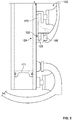
- Fig. 3 is a simplified cross sectional view of a portion of a turbine engine 100 in accordance with some embodiments of the present disclosure.
- the turbine engine 100 comprises a first oil sump 102, second oil sump 103, and oil drainage conduit 130 fluidically connecting the first oil sump 102 and second oil sump 103.
- the turbine engine 100 may have a rotatable shaft 101 oriented vertically.
- the turbine engine 100 may have a rotatable shaft 101 oriented at less than 90 degrees from vertical.
- the turbine engine 100 may be in a shutdown mode.
- First oil sump 102 is disposed at a first axial position relative to rotatable shaft 101.
- First oil sump 102 has a selected critical vertical level 131.
- the selected critical vertical level 131 may be the level at which accumulating oil will exceed a volume at which oil may be accumulated safely and without adverse consequences to the turbine engine 100.
- the selected critical vertical level 131 may be the level at which accumulating oil will exceed the vertical height of an axially-extending arm 123 of first inner member 121 and thus contact the seal 105. In other words, the seal 105 will be exposed to oil if the vertical level of the oil collected in the first oil sump 102 exceeds the selected critical vertical level 131.
- the selected critical vertical level 131 may be the vertical level of the seal 105.
- the selected critical vertical level 131 may be any vertical level at which it is undesirable to have accumulating oil rise above.
- Oil drainage conduit 130 may comprise one or more conduit members that fluidically connect first oil sump 102 and second oil sump 103.
- the second oil sump 103 is disposed at a second axial position relative to the rotatable shaft 101. With rotatable shaft 101 positioned vertically or at less than 90 degrees from vertical, the second oil sump 103 is positioned at a lower elevation than the elevation of the first oil sump 102.
- the oil drainage conduit 130 may be disposed entirely or partially within the hollow shaft 101, as shown in Figure 3 .
- the interface between the oil drainage conduit 130 and inner diameter 117 of shaft 101 may comprise one or more seals 136, which may take the form of elastomeric packings, sealing rings, O-rings, or other suitable static seals.
- the turbine engine 100 includes a T-shaped oil drainage conduit 130.
- the oil drainage conduit 130 has one or more inlets 132 positioned in the first oil sump 102 to effect oil drainage by gravity from the first oil sump 102 to the second oil sump 103.
- the one or more inlets 132 may be sized and positioned within the first oil sump 102 to prevent the vertical level of oil collected in the first oil sump 102 from exceeding the selected critical vertical level 131.
- the one or more inlets 132 may be positioned at a vertical level below the selected critical vertical level 131.
- the one or more inlets 132 may pass through the hollow shaft 101 (i.e. passing from the outer diameter 118 to the inner diameter 117), and may be spaced evenly about the circumference of the hollow shaft 101.
- the one or more inlets 132 may be positioned in the first oil sump 102 such that the lower edge of the inlet 132 defines an inlet vertical level 133.
- the inlet vertical level 133 may be below the selected critical vertical level 131.
- the oil drainage conduit 130 may be configured to selectively secure oil drainage from the first oil sump 102 to the second oil sump 103 when the turbine engine 100 leaves a shutdown mode.
- the oil drainage conduit 130 may comprise a flow blocking device 134 configured to fluidically isolate the oil drainage conduit 130 from the first oil sump 102 upon rotation of the shaft 101.
- the flow blocking device 134 may be configured to prevent fluid (e.g., air and oil) flow through the oil drainage conduit 130.
- the flow blocking device 134 comprises one or more flaps 135 positioned across the oil drainage conduit 130.
- oil drainage flow through the oil drainage conduit 130 is sufficient to lift one end of the flap 135 away from the oil drainage conduit 130, thus permitting flow from first oil sump 102 to second oil sump 103.
- centrifugal forces sealingly engage the flap 135 with the oil drainage conduit 130 to prevent flow through the oil drainage conduit 130.
- the flaps 135 under centrifugal forces sealingly engage with the oil drainage conduit 130 to fluidically isolate the oil drainage conduit 130 from the first oil sump 102.
- flaps 135 are disposed at a junction or bend of the oil drainage conduit 130, the flaps 135 may be positioned elsewhere in the oil drainage conduit 130 such as at the inlet 132.
- Flow blocking devices 134 may also be disposed external to the oil drainage conduit 130.
- a flow blocking device 134 may be disposed within the first oil sump 102 at the inlet 132 to fluidically isolate the oil drainage conduit 130 from the first oil sump 102.
- additional flow blocking devices 134 are contemplated for use with the present disclosure, including but not limited to balls on ramped seats and/or flyweights that would seal the oil drainage conduit 130 during operation of the turbine engine 100.
- the oil drainage conduit 130 may include a flow blocking device for preventing oil flow from the second oil sump 103 to the first oil sump 102.
- a flow blocking device may be implemented as, for example, a check valve.
- a flow blocking device may be disposed in the drainage path and configured to selectively close the drainage path during rotation of the shaft 101.
- first oil sump 102 and second oil sump 103 may be in fluid communication during operation of the turbine engine 100.
- Oil drainage conduit 130 may therefore be used to equalize pressure between the first oil sump 102 and second oil sump 103 during operation of the turbine engine 100.
- the second oil sump 103 may comprise an expanded second oil sump cover 140.
- the expanded second oil sump cover 140 may be dimensioned to accommodate the additional oil flow from the first oil sump 102 to second oil sump 103.
- the expanded second oil sump cover 140 may be dimensioned to contain substantially all of the oil of the first oil sump 102 and second oil sump 103 when the turbine engine 100 is shutdown in a vertical orientation.
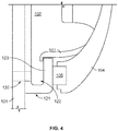
- FIG. 4 is a detailed simplified cross sectional view of a portion of a turbine engine 100 in accordance with some embodiments of the present disclosure.
- an oil baffle 141 may be disposed above the seal 105 when the shaft 101 is in a vertical orientation.
- the oil baffle 141 may extend between the first sump cover 104 and first inner member 121, and may be angled or otherwise structured to direct accumulating oil toward the inlet 132 of the oil drainage conduit 130.
- the oil baffle 141 may comprise a continuously sloping top surface.
- the oil baffle 141 may extend between the first sump cover 104 and the axially-extending arm 123 of the first inner member 121.
- the oil baffle 141 may be annular.
- the oil baffle 141 protects the seal 105 from excessive contact with accumulating oil in the first oil sump 102 when the turbine engine 100 is shut down with shaft 101 in a vertical orientation. Oil in the first oil sump 102 that would normally accumulate in any low-lying areas proximate or contacting the seal 105 is now directed to the first volume 122, and more generally toward the inlet 132 so that the oil can be safely drained to second oil sump 103.
- the additional oil disposed in the second oil sump 103 may require scavenging via a lubrication and scavenge system in order to restore a sufficient volume of oil to the first oil sump 102.
- the present disclosure additionally provides methods of preventing a level of oil collected in an oil sump from exceeding a selected critical vertical level of the sump.
- Method 500 presented in Figure 5 , is such a method.
- Method 500 is intended for use in a turbine engine 100 in a shutdown mode with one or more rotatable shafts in a vertical orientation.
- the turbine engine 100 comprises a first oil sump 102 with a selected critical vertical level 131 and a second oil sump 103 positioned below the first oil sump 102.
- Method 500 begins at Block 501.
- an oil drainage conduit 130 is provided between the first oil sump 102 and the second oil sump 103.
- the oil drainage conduit 130 may effect oil drainage by gravity from the first oil sump 102 to the second oil sump 103.
- the oil drainage conduit 130 may have an inlet 132 positioned in the first oil sump 102 at an inlet vertical level 133 below the selected critical vertical level 131.
- the oil drainage conduit 130 may be wholly or partly disposed within a hollow shaft 101 of the turbine engine 100.
- the inlet 132 may comprise one or more inlets passing from an outer diameter 118 to an inner diameter 117 of the hollow shaft 101.
- the inlets 132 may be sized and positioned to ensure oil accumulation does not rise above the selected critical vertical level 131.
- the steps indicated at Blocks 505 and 507 are optional, as indicated by the dashed line boxes.
- flow of oil from the second oil sump 103 to the first oil sump 102 may be prevented.
- the oil drainage conduit 130 may include a check valve disposed therein for ensuring oil flow only from the first oil sump 102 to the second oil sump 103.
- Oil flow through the oil drainage conduit 130 may be prevented when one or more shafts are rotating at Block 507.
- the oil drainage conduit 130 may comprise a flow blocking device 134 configured to fluidically isolate the oil drainage conduit 130 from the first oil sump 102 upon rotation of the shaft 101.
- the flow blocking device 134 may be configured to prevent flow through the oil drainage conduit 130.
- the flow blocking device 134 may comprise one or more flaps 135 positioned across the oil drainage conduit 130. When the turbine engine 100 is in a shutdown condition, oil drainage flow through the oil drainage conduit 130 is sufficient to lift one end of the flap 135 away from the oil drainage conduit 130, thus permitting flow from first oil sump 102 to second oil sump 103.
- the flaps 135 under centrifugal forces sealingly engage with the oil drainage conduit 130 to fluidically isolate the oil drainage conduit 130 from the first oil sump 102.
- Method 500 may further comprise providing an oil baffle 141 above the selected critical vertical level 131, the oil baffle 141 configured to direct oil toward the inlet 132 of the oil drainage conduit 130.
- Method 500 ends at Block 511.
- the presently disclosed systems and methods have numerous advantages over existing lubrication sump systems.
- the disclosed systems and methods prevent the accumulation of oil on a sump seal when a turbine engine is shut down in a vertical orientation.
- the prevention of oil accumulation in turn prevents flooding of the seal, coking of oil upon engine restart, and reduces the likelihood of oil leakage, fires, and other hazards to the engine.
- By therefore improving the longevity of the sump seal, maintenance and repair costs are greatly reduced.
- the present disclosure additional provides a relatively simple means for addressing the problem of oil accumulating on a sump seal, thus avoiding the complex and expensive use of piping, pumps, valves, and external tanks that could otherwise be implemented.
Landscapes
- Engineering & Computer Science (AREA)
- General Engineering & Computer Science (AREA)
- Mechanical Engineering (AREA)
- Sealing Using Fluids, Sealing Without Contact, And Removal Of Oil (AREA)
Claims (15)
- Gasturbinenmotor (100) in einem Abschaltmodus, wobei der Motor Folgendes umfasst:eine oder mehrere drehbare Wellen (101), die mit einer Drehachse von weniger als 90 Grad zur Vertikalen ausgerichtet ist/sind;ein erster Ölsumpf (102) in einer ersten axialen Position relativ zur einen oder den mehreren drehbaren Wellen, wobei der erste Ölsumpf einen ausgewählten kritischen vertikalen Stand (131) aufweist;ein zweiter Ölsumpf (103) in einer zweiten axialen Position relativ zur einen oder den mehreren drehbaren Wellen, sodass der zweite Ölsumpf auf einer Höhe positioniert ist, die niedriger als die Höhe des ersten Ölsumpfes ist; undeine Ölablaufleitung (130), die fluidisch mit dem ersten Ölsumpf und dem zweiten Ölsumpf verbunden ist, wobei die Ölablaufleitung einen Einlass (132) aufweist, der in dem ersten Ölsumpf auf einem vertikalen Stand unterhalb des ausgewählten kritischen vertikalen Stands positioniert ist, um dadurch einen Ölablauf durch Schwerkraft aus dem ersten Ölsumpf zum zweiten Ölsumpf zu bewirken, um zu verhindern, dass der in dem ersten Ölsumpf angesammelte Ölstand den ausgewählten kritischen vertikalen Stand überschreitet.
- Motor nach Anspruch 1, wobei die Ölablaufleitung (130) so konfiguriert ist, um den Ölablauf sicherzustellen, wenn der Motor einen Abschaltmodus verlässt.
- Motor nach Anspruch 1 oder 2, ferner umfassend eine Stromblockiervorrichtung (134), die konfiguriert ist, um die Ölablaufleitung (130) fluidisch von dem ersten Ölsumpf (102) bei Drehung der einen oder der mehreren drehbaren Wellen (101) zu isolieren.
- Motor nach Anspruch 3, wobei die Stromblockiervorrichtung (134) eine oder mehrere Klappen (135) umfasst, die über der Ölablaufleitung (130) positioniert sind, und wobei Zentrifugalkräfte, die durch die Drehung der einen oder mehreren drehbaren Wellen (101) erzeugt werden, die Klappen abdichtend mit der Ölablaufleitung in Eingriff bringen, um die Ölablaufleitung fluidisch von dem ersten Ölsumpf (102) zu isolieren.
- Motor nach Anspruch 1 oder 2, ferner umfassend eine Stromblockiervorrichtung (134), die innerhalb der Ölablaufleitung (130) angeordnet und konfiguriert ist, um einen Ölstrom von dem zweiten Ölsumpf (103) zum ersten Ölsumpf (102) zu verhindern.
- Motor nach einem der vorhergehenden Ansprüche, ferner umfassend eine Dichtung (105), die nahe dem ersten Ölsumpf (102) positioniert ist, sodass die Dichtung Öl ausgesetzt ist, wenn der in dem ersten Ölsumpf angesammelte Ölstand den ausgewählten kritischen vertikalen Stand (131) überschreitet.
- Motor nach Anspruch 6, wobei der Einlass (132) mehr als einen Einlass umfasst, der durch die drehbare Welle (101) verläuft.
- Motor nach Anspruch 6 oder 7, ferner umfassend ein Ölfangblech (141), das vertikal über der Dichtung (105) angeordnet und konfiguriert ist, um Öl zu der Ölablaufleitung (130) zu leiten.
- Motor nach Anspruch 8, wobei sich das Ölfangblech (141) zwischen einer Sumpfabdeckung (104) und einem Innenelement (121) erstreckt, das radial von der Dichtung nach innen positioniert ist.
- Motor nach Anspruch 8 oder 9, wobei das Ölfangblech (141) kreisförmig ist.
- Motor nach einem vorhergehenden Anspruch, wobei eine erste der einen oder mehreren drehbaren Wellen hohl ist und jeder der ersten Ölsümpfe (102) und der zweiten Ölsümpfe (103) um die hohle drehbare Welle (101) angeordnet ist und wobei die Ölablaufleitung (130) zumindest teilweise innerhalb der hohlen drehbaren Welle angeordnet ist.
- Motor nach Anspruch 11, wobei die Dichtung (105) zwischen einer ersten Ölsumpfabdeckung und der hohlen drehbaren Welle angeordnet ist und zumindest ein Teil der Ölablaufleitung innerhalb der hohlen drehbaren Welle angeordnet ist.
- Verfahren zum Betreiben eines Gasturbinenmotors (100) in einem Abschaltmodus, aufweisend eine oder mehrere drehbare Wellen (101), die mit einer Drehachse von weniger als 90 Grad zur Vertikalen ausgerichtet ist/sind, wobei der Motor einen ersten Ölsumpf (102) mit einem ausgewählten kritischen vertikalen Stand (131) aufweist und einen zweiten Ölsumpf (103) aufweist, der auf einer niedrigeren Höhe als die Höhe des ersten Ölsumpfes positioniert ist, wobei das Verfahren verhindert, dass ein in dem ersten Ölsumpf angesammelter Ölstand das ausgewählte kritische vertikale Stand überschreitet, wobei das Verfahren Folgendes umfasst:
Bereitstellen einer Ölablaufleitung (130) zwischen dem ersten Ölsumpf und dem zweiten Ölsumpf, wobei die Ölablaufleitung einen Einlass (132) aufweist, der in dem ersten Ölsumpf in einem vertikalen Stand unterhalb des ausgewählten kritischen vertikalen Stands positioniert ist, um dadurch einen Ölablauf durch Schwerkraft vom ersten Ölsumpf zum zweiten Ölsumpf zu bewirken. - Verfahren nach Anspruch 13, ferner umfassend das Verhindern des Ölstroms vom zweiten Ölsumpf zum ersten Ölsumpf.
- Verfahren nach Anspruch 13 oder 14, ferner umfassend das Verhindern des Ölstroms durch die Ölablaufleitung (130), wenn sich die eine oder die mehreren Wellen (101) drehen.
Applications Claiming Priority (1)
| Application Number | Priority Date | Filing Date | Title |
|---|---|---|---|
| US16/007,679 US10851689B2 (en) | 2018-06-13 | 2018-06-13 | Drainage path for a bearing sump in a vertically oriented turbine engine |
Publications (2)
| Publication Number | Publication Date |
|---|---|
| EP3581769A1 EP3581769A1 (de) | 2019-12-18 |
| EP3581769B1 true EP3581769B1 (de) | 2020-10-14 |
Family
ID=66685395
Family Applications (1)
| Application Number | Title | Priority Date | Filing Date |
|---|---|---|---|
| EP19177579.0A Active EP3581769B1 (de) | 2018-06-13 | 2019-05-31 | Drainagepfad für einen lagersumpf in einem vertikal ausgerichteten turbinenmotor |
Country Status (3)
| Country | Link |
|---|---|
| US (1) | US10851689B2 (de) |
| EP (1) | EP3581769B1 (de) |
| CA (1) | CA3043917A1 (de) |
Families Citing this family (5)
| Publication number | Priority date | Publication date | Assignee | Title |
|---|---|---|---|---|
| IT202100003647A1 (it) * | 2021-02-17 | 2022-08-17 | Nuovo Pignone Tecnologie Srl | Serbatoio di contenimento di allagamento |
| US12203412B2 (en) | 2022-06-10 | 2025-01-21 | Rtx Corporation | Turbine engine shaft plug |
| US12320418B2 (en) * | 2022-06-22 | 2025-06-03 | General Electric Company | Gearbox assembly with lubricant extraction volume ratio |
| US12326115B2 (en) * | 2022-06-22 | 2025-06-10 | General Electric Company | Gearbox assembly with lubricant extraction volume ratio |
| US12276333B2 (en) * | 2023-06-21 | 2025-04-15 | General Electric Company | Gearbox assembly lubrication system for a turbine engine |
Family Cites Families (15)
| Publication number | Priority date | Publication date | Assignee | Title |
|---|---|---|---|---|
| GB996112A (en) | 1963-09-02 | 1965-06-23 | Rolls Royce | Bearing assembly |
| US3452839A (en) * | 1966-11-07 | 1969-07-01 | Judson S Swearingen | Reduction of power losses in high speed bearing lubrication |
| GB1360489A (en) * | 1971-06-03 | 1974-07-17 | Weir Pumps Ltd | Sealed lubricating system module |
| DE3542316A1 (de) * | 1985-09-09 | 1987-03-12 | Kraftwerk Union Ag | Einrichtung zur leckoel-freien lageroel-abfuehrung an gleitlagern fuer umlaufende wellen hochtouriger maschinen |
| US4856273A (en) * | 1988-07-21 | 1989-08-15 | General Motors Corporation | Secondary oil system for gas turbine engine |
| GB9908845D0 (en) * | 1999-04-19 | 1999-06-16 | Seneca Tech Ltd | Inverted engine configuration |
| US7360361B2 (en) * | 2005-04-09 | 2008-04-22 | Advanced Propulsion Technologies, Inc. | Turbocharger |
| DE102005031804A1 (de) * | 2005-07-07 | 2007-01-18 | Mtu Aero Engines Gmbh | Schmiermittelsystem |
| US8210316B2 (en) * | 2006-12-12 | 2012-07-03 | United Technologies Corporation | Oil scavenge system for a gas turbine engine |
| US8893856B2 (en) * | 2008-07-24 | 2014-11-25 | Honeywell International Inc. | Gravity scavenged generator with integral engine oil tank |
| IT1396518B1 (it) * | 2009-12-04 | 2012-12-14 | Nuovo Pignone Spa | Una unita' compressore ed un metodo per processare un fluido di lavoro |
| JP5834538B2 (ja) * | 2011-06-27 | 2015-12-24 | 株式会社Ihi | 廃熱発電装置 |
| AR087583A1 (es) * | 2011-08-16 | 2014-04-03 | Weir Floway Inc | Conjunto de cojinete para una bomba de turbina vertical |
| BR112015013832A2 (pt) * | 2012-12-14 | 2017-07-11 | Gen Electric | drenos de óleo alimentados por pressão |
| US9944399B2 (en) * | 2014-08-07 | 2018-04-17 | Pratt & Whitney Canada Corp. | Seal assembly for a bearing assembly in a gas turbine engine |
-
2018
- 2018-06-13 US US16/007,679 patent/US10851689B2/en active Active
-
2019
- 2019-05-22 CA CA3043917A patent/CA3043917A1/en active Pending
- 2019-05-31 EP EP19177579.0A patent/EP3581769B1/de active Active
Non-Patent Citations (1)
| Title |
|---|
| None * |
Also Published As
| Publication number | Publication date |
|---|---|
| CA3043917A1 (en) | 2019-12-13 |
| EP3581769A1 (de) | 2019-12-18 |
| US20190383181A1 (en) | 2019-12-19 |
| US10851689B2 (en) | 2020-12-01 |
Similar Documents
| Publication | Publication Date | Title |
|---|---|---|
| EP3581769A1 (de) | Drainagepfad für einen lagersumpf in einem vertikal ausgerichteten turbinenmotor | |
| US11555418B2 (en) | Oil supply system for a gas turbine engine | |
| EP2535529B1 (de) | Lagerkammervorrichtung | |
| EP2657465B1 (de) | Abschwächung der Wirbelpumpenwirkung stromaufwärts einer Öldichtung | |
| EP2224120B1 (de) | Schmierölhilfspumpe einer Getriebe-Antriebseinheit für Gasturbinenturbofantriebwerk | |
| RU2486358C2 (ru) | Способ и устройство выравнивания давления в камере для подшипников турбореактивного двигателя | |
| EP2672078B1 (de) | Entölerdichtung | |
| EP1936123A2 (de) | Ölrücklaufsystem für ein Gasturbinentriebwerk | |
| EP2586534B1 (de) | Fliehkraftabscheider, Verbrennungsmotor und Fliehkraftabscheideranordnung und Verfahren zum Abscheiden von Kontaminanten aus Kurbelgehäusegas | |
| RU2670711C1 (ru) | Патрубок для отвода дренажных жидкостей для силовой установки | |
| JP2005291202A (ja) | 油分離器および油分離方法 | |
| US9829007B2 (en) | Turbine sealing system | |
| US4570947A (en) | Gas sealing and fluid scavenge apparatus | |
| US9175576B2 (en) | Turbomachine | |
| US11549443B2 (en) | Sealing arrangement with vent for an engine component with a service port | |
| EP2650485B1 (de) | Wellendichtungssystem für Dampfturbinen | |
| US3392804A (en) | Lubrication system | |
| US20140248125A1 (en) | Chamber fluid removal system | |
| US10056805B2 (en) | Venting generator assemblies | |
| EP2538037B1 (de) | Motorlagergehäuse | |
| US12104528B1 (en) | Forced air supply system for engine cavity under negative-G force | |
| US12215706B2 (en) | Rotary machine and primary motor-pump assembly provided with this rotary machine | |
| US20200386231A1 (en) | Liquid-Injected Screw Compressor | |
| US12221927B2 (en) | Flammable fluid reservoir | |
| CN208734736U (zh) | 一种呼吸阀小机轴承盖 |
Legal Events
| Date | Code | Title | Description |
|---|---|---|---|
| PUAI | Public reference made under article 153(3) epc to a published international application that has entered the european phase |
Free format text: ORIGINAL CODE: 0009012 |
|
| STAA | Information on the status of an ep patent application or granted ep patent |
Free format text: STATUS: THE APPLICATION HAS BEEN PUBLISHED |
|
| AK | Designated contracting states |
Kind code of ref document: A1 Designated state(s): AL AT BE BG CH CY CZ DE DK EE ES FI FR GB GR HR HU IE IS IT LI LT LU LV MC MK MT NL NO PL PT RO RS SE SI SK SM TR |
|
| AX | Request for extension of the european patent |
Extension state: BA ME |
|
| STAA | Information on the status of an ep patent application or granted ep patent |
Free format text: STATUS: REQUEST FOR EXAMINATION WAS MADE |
|
| 17P | Request for examination filed |
Effective date: 20200327 |
|
| RBV | Designated contracting states (corrected) |
Designated state(s): AL AT BE BG CH CY CZ DE DK EE ES FI FR GB GR HR HU IE IS IT LI LT LU LV MC MK MT NL NO PL PT RO RS SE SI SK SM TR |
|
| RIC1 | Information provided on ipc code assigned before grant |
Ipc: F01D 25/00 20060101ALI20200423BHEP Ipc: F01D 21/00 20060101AFI20200423BHEP |
|
| GRAP | Despatch of communication of intention to grant a patent |
Free format text: ORIGINAL CODE: EPIDOSNIGR1 |
|
| STAA | Information on the status of an ep patent application or granted ep patent |
Free format text: STATUS: GRANT OF PATENT IS INTENDED |
|
| RIN1 | Information on inventor provided before grant (corrected) |
Inventor name: ENGEL, CHADD |
|
| INTG | Intention to grant announced |
Effective date: 20200612 |
|
| GRAS | Grant fee paid |
Free format text: ORIGINAL CODE: EPIDOSNIGR3 |
|
| GRAA | (expected) grant |
Free format text: ORIGINAL CODE: 0009210 |
|
| STAA | Information on the status of an ep patent application or granted ep patent |
Free format text: STATUS: THE PATENT HAS BEEN GRANTED |
|
| AK | Designated contracting states |
Kind code of ref document: B1 Designated state(s): AL AT BE BG CH CY CZ DE DK EE ES FI FR GB GR HR HU IE IS IT LI LT LU LV MC MK MT NL NO PL PT RO RS SE SI SK SM TR |
|
| REG | Reference to a national code |
Ref country code: GB Ref legal event code: FG4D |
|
| REG | Reference to a national code |
Ref country code: AT Ref legal event code: REF Ref document number: 1323806 Country of ref document: AT Kind code of ref document: T Effective date: 20201015 Ref country code: CH Ref legal event code: EP |
|
| REG | Reference to a national code |
Ref country code: DE Ref legal event code: R096 Ref document number: 602019000953 Country of ref document: DE |
|
| REG | Reference to a national code |
Ref country code: IE Ref legal event code: FG4D |
|
| REG | Reference to a national code |
Ref country code: AT Ref legal event code: MK05 Ref document number: 1323806 Country of ref document: AT Kind code of ref document: T Effective date: 20201014 |
|
| REG | Reference to a national code |
Ref country code: NL Ref legal event code: MP Effective date: 20201014 |
|
| PG25 | Lapsed in a contracting state [announced via postgrant information from national office to epo] |
Ref country code: RS Free format text: LAPSE BECAUSE OF FAILURE TO SUBMIT A TRANSLATION OF THE DESCRIPTION OR TO PAY THE FEE WITHIN THE PRESCRIBED TIME-LIMIT Effective date: 20201014 Ref country code: PT Free format text: LAPSE BECAUSE OF FAILURE TO SUBMIT A TRANSLATION OF THE DESCRIPTION OR TO PAY THE FEE WITHIN THE PRESCRIBED TIME-LIMIT Effective date: 20210215 Ref country code: FI Free format text: LAPSE BECAUSE OF FAILURE TO SUBMIT A TRANSLATION OF THE DESCRIPTION OR TO PAY THE FEE WITHIN THE PRESCRIBED TIME-LIMIT Effective date: 20201014 Ref country code: NO Free format text: LAPSE BECAUSE OF FAILURE TO SUBMIT A TRANSLATION OF THE DESCRIPTION OR TO PAY THE FEE WITHIN THE PRESCRIBED TIME-LIMIT Effective date: 20210114 Ref country code: GR Free format text: LAPSE BECAUSE OF FAILURE TO SUBMIT A TRANSLATION OF THE DESCRIPTION OR TO PAY THE FEE WITHIN THE PRESCRIBED TIME-LIMIT Effective date: 20210115 |
|
| REG | Reference to a national code |
Ref country code: LT Ref legal event code: MG4D |
|
| PG25 | Lapsed in a contracting state [announced via postgrant information from national office to epo] |
Ref country code: PL Free format text: LAPSE BECAUSE OF FAILURE TO SUBMIT A TRANSLATION OF THE DESCRIPTION OR TO PAY THE FEE WITHIN THE PRESCRIBED TIME-LIMIT Effective date: 20201014 Ref country code: LV Free format text: LAPSE BECAUSE OF FAILURE TO SUBMIT A TRANSLATION OF THE DESCRIPTION OR TO PAY THE FEE WITHIN THE PRESCRIBED TIME-LIMIT Effective date: 20201014 Ref country code: IS Free format text: LAPSE BECAUSE OF FAILURE TO SUBMIT A TRANSLATION OF THE DESCRIPTION OR TO PAY THE FEE WITHIN THE PRESCRIBED TIME-LIMIT Effective date: 20210214 Ref country code: SE Free format text: LAPSE BECAUSE OF FAILURE TO SUBMIT A TRANSLATION OF THE DESCRIPTION OR TO PAY THE FEE WITHIN THE PRESCRIBED TIME-LIMIT Effective date: 20201014 Ref country code: BG Free format text: LAPSE BECAUSE OF FAILURE TO SUBMIT A TRANSLATION OF THE DESCRIPTION OR TO PAY THE FEE WITHIN THE PRESCRIBED TIME-LIMIT Effective date: 20210114 Ref country code: ES Free format text: LAPSE BECAUSE OF FAILURE TO SUBMIT A TRANSLATION OF THE DESCRIPTION OR TO PAY THE FEE WITHIN THE PRESCRIBED TIME-LIMIT Effective date: 20201014 Ref country code: AT Free format text: LAPSE BECAUSE OF FAILURE TO SUBMIT A TRANSLATION OF THE DESCRIPTION OR TO PAY THE FEE WITHIN THE PRESCRIBED TIME-LIMIT Effective date: 20201014 |
|
| PG25 | Lapsed in a contracting state [announced via postgrant information from national office to epo] |
Ref country code: NL Free format text: LAPSE BECAUSE OF FAILURE TO SUBMIT A TRANSLATION OF THE DESCRIPTION OR TO PAY THE FEE WITHIN THE PRESCRIBED TIME-LIMIT Effective date: 20201014 Ref country code: HR Free format text: LAPSE BECAUSE OF FAILURE TO SUBMIT A TRANSLATION OF THE DESCRIPTION OR TO PAY THE FEE WITHIN THE PRESCRIBED TIME-LIMIT Effective date: 20201014 |
|
| REG | Reference to a national code |
Ref country code: DE Ref legal event code: R097 Ref document number: 602019000953 Country of ref document: DE |
|
| PG25 | Lapsed in a contracting state [announced via postgrant information from national office to epo] |
Ref country code: CZ Free format text: LAPSE BECAUSE OF FAILURE TO SUBMIT A TRANSLATION OF THE DESCRIPTION OR TO PAY THE FEE WITHIN THE PRESCRIBED TIME-LIMIT Effective date: 20201014 Ref country code: SK Free format text: LAPSE BECAUSE OF FAILURE TO SUBMIT A TRANSLATION OF THE DESCRIPTION OR TO PAY THE FEE WITHIN THE PRESCRIBED TIME-LIMIT Effective date: 20201014 Ref country code: SM Free format text: LAPSE BECAUSE OF FAILURE TO SUBMIT A TRANSLATION OF THE DESCRIPTION OR TO PAY THE FEE WITHIN THE PRESCRIBED TIME-LIMIT Effective date: 20201014 Ref country code: EE Free format text: LAPSE BECAUSE OF FAILURE TO SUBMIT A TRANSLATION OF THE DESCRIPTION OR TO PAY THE FEE WITHIN THE PRESCRIBED TIME-LIMIT Effective date: 20201014 Ref country code: LT Free format text: LAPSE BECAUSE OF FAILURE TO SUBMIT A TRANSLATION OF THE DESCRIPTION OR TO PAY THE FEE WITHIN THE PRESCRIBED TIME-LIMIT Effective date: 20201014 Ref country code: RO Free format text: LAPSE BECAUSE OF FAILURE TO SUBMIT A TRANSLATION OF THE DESCRIPTION OR TO PAY THE FEE WITHIN THE PRESCRIBED TIME-LIMIT Effective date: 20201014 |
|
| PLBE | No opposition filed within time limit |
Free format text: ORIGINAL CODE: 0009261 |
|
| STAA | Information on the status of an ep patent application or granted ep patent |
Free format text: STATUS: NO OPPOSITION FILED WITHIN TIME LIMIT |
|
| PG25 | Lapsed in a contracting state [announced via postgrant information from national office to epo] |
Ref country code: DK Free format text: LAPSE BECAUSE OF FAILURE TO SUBMIT A TRANSLATION OF THE DESCRIPTION OR TO PAY THE FEE WITHIN THE PRESCRIBED TIME-LIMIT Effective date: 20201014 |
|
| 26N | No opposition filed |
Effective date: 20210715 |
|
| PG25 | Lapsed in a contracting state [announced via postgrant information from national office to epo] |
Ref country code: AL Free format text: LAPSE BECAUSE OF FAILURE TO SUBMIT A TRANSLATION OF THE DESCRIPTION OR TO PAY THE FEE WITHIN THE PRESCRIBED TIME-LIMIT Effective date: 20201014 Ref country code: IT Free format text: LAPSE BECAUSE OF FAILURE TO SUBMIT A TRANSLATION OF THE DESCRIPTION OR TO PAY THE FEE WITHIN THE PRESCRIBED TIME-LIMIT Effective date: 20201014 |
|
| PG25 | Lapsed in a contracting state [announced via postgrant information from national office to epo] |
Ref country code: SI Free format text: LAPSE BECAUSE OF FAILURE TO SUBMIT A TRANSLATION OF THE DESCRIPTION OR TO PAY THE FEE WITHIN THE PRESCRIBED TIME-LIMIT Effective date: 20201014 |
|
| REG | Reference to a national code |
Ref country code: DE Ref legal event code: R119 Ref document number: 602019000953 Country of ref document: DE |
|
| PG25 | Lapsed in a contracting state [announced via postgrant information from national office to epo] |
Ref country code: MC Free format text: LAPSE BECAUSE OF FAILURE TO SUBMIT A TRANSLATION OF THE DESCRIPTION OR TO PAY THE FEE WITHIN THE PRESCRIBED TIME-LIMIT Effective date: 20201014 Ref country code: LU Free format text: LAPSE BECAUSE OF NON-PAYMENT OF DUE FEES Effective date: 20210531 |
|
| REG | Reference to a national code |
Ref country code: BE Ref legal event code: MM Effective date: 20210531 |
|
| PG25 | Lapsed in a contracting state [announced via postgrant information from national office to epo] |
Ref country code: IE Free format text: LAPSE BECAUSE OF NON-PAYMENT OF DUE FEES Effective date: 20210531 Ref country code: DE Free format text: LAPSE BECAUSE OF NON-PAYMENT OF DUE FEES Effective date: 20211201 |
|
| PG25 | Lapsed in a contracting state [announced via postgrant information from national office to epo] |
Ref country code: IS Free format text: LAPSE BECAUSE OF FAILURE TO SUBMIT A TRANSLATION OF THE DESCRIPTION OR TO PAY THE FEE WITHIN THE PRESCRIBED TIME-LIMIT Effective date: 20210214 |
|
| PG25 | Lapsed in a contracting state [announced via postgrant information from national office to epo] |
Ref country code: BE Free format text: LAPSE BECAUSE OF NON-PAYMENT OF DUE FEES Effective date: 20210531 |
|
| REG | Reference to a national code |
Ref country code: CH Ref legal event code: PL |
|
| PG25 | Lapsed in a contracting state [announced via postgrant information from national office to epo] |
Ref country code: LI Free format text: LAPSE BECAUSE OF NON-PAYMENT OF DUE FEES Effective date: 20220531 Ref country code: CH Free format text: LAPSE BECAUSE OF NON-PAYMENT OF DUE FEES Effective date: 20220531 |
|
| PG25 | Lapsed in a contracting state [announced via postgrant information from national office to epo] |
Ref country code: CY Free format text: LAPSE BECAUSE OF FAILURE TO SUBMIT A TRANSLATION OF THE DESCRIPTION OR TO PAY THE FEE WITHIN THE PRESCRIBED TIME-LIMIT Effective date: 20201014 |
|
| P01 | Opt-out of the competence of the unified patent court (upc) registered |
Effective date: 20230528 |
|
| PG25 | Lapsed in a contracting state [announced via postgrant information from national office to epo] |
Ref country code: HU Free format text: LAPSE BECAUSE OF FAILURE TO SUBMIT A TRANSLATION OF THE DESCRIPTION OR TO PAY THE FEE WITHIN THE PRESCRIBED TIME-LIMIT; INVALID AB INITIO Effective date: 20190531 |
|
| GBPC | Gb: european patent ceased through non-payment of renewal fee |
Effective date: 20230531 |
|
| PG25 | Lapsed in a contracting state [announced via postgrant information from national office to epo] |
Ref country code: MK Free format text: LAPSE BECAUSE OF FAILURE TO SUBMIT A TRANSLATION OF THE DESCRIPTION OR TO PAY THE FEE WITHIN THE PRESCRIBED TIME-LIMIT Effective date: 20201014 Ref country code: GB Free format text: LAPSE BECAUSE OF NON-PAYMENT OF DUE FEES Effective date: 20230531 |
|
| PG25 | Lapsed in a contracting state [announced via postgrant information from national office to epo] |
Ref country code: MT Free format text: LAPSE BECAUSE OF FAILURE TO SUBMIT A TRANSLATION OF THE DESCRIPTION OR TO PAY THE FEE WITHIN THE PRESCRIBED TIME-LIMIT Effective date: 20201014 |
|
| PGFP | Annual fee paid to national office [announced via postgrant information from national office to epo] |
Ref country code: FR Payment date: 20250526 Year of fee payment: 7 |
|
| PG25 | Lapsed in a contracting state [announced via postgrant information from national office to epo] |
Ref country code: TR Free format text: LAPSE BECAUSE OF FAILURE TO SUBMIT A TRANSLATION OF THE DESCRIPTION OR TO PAY THE FEE WITHIN THE PRESCRIBED TIME-LIMIT Effective date: 20201014 |