EP3581749A1 - Method for adjusting a force that has to be applied by a user to operate a lid - Google Patents
Method for adjusting a force that has to be applied by a user to operate a lid Download PDFInfo
- Publication number
- EP3581749A1 EP3581749A1 EP19179701.8A EP19179701A EP3581749A1 EP 3581749 A1 EP3581749 A1 EP 3581749A1 EP 19179701 A EP19179701 A EP 19179701A EP 3581749 A1 EP3581749 A1 EP 3581749A1
- Authority
- EP
- European Patent Office
- Prior art keywords
- lid
- actuator
- unit
- drive unit
- angle
- Prior art date
- Legal status (The legal status is an assumption and is not a legal conclusion. Google has not performed a legal analysis and makes no representation as to the accuracy of the status listed.)
- Withdrawn
Links
Images


Classifications
-
- E—FIXED CONSTRUCTIONS
- E05—LOCKS; KEYS; WINDOW OR DOOR FITTINGS; SAFES
- E05F—DEVICES FOR MOVING WINGS INTO OPEN OR CLOSED POSITION; CHECKS FOR WINGS; WING FITTINGS NOT OTHERWISE PROVIDED FOR, CONCERNED WITH THE FUNCTIONING OF THE WING
- E05F15/00—Power-operated mechanisms for wings
- E05F15/60—Power-operated mechanisms for wings using electrical actuators
- E05F15/603—Power-operated mechanisms for wings using electrical actuators using rotary electromotors
- E05F15/611—Power-operated mechanisms for wings using electrical actuators using rotary electromotors for swinging wings
- E05F15/616—Power-operated mechanisms for wings using electrical actuators using rotary electromotors for swinging wings operated by push-pull mechanisms
- E05F15/622—Power-operated mechanisms for wings using electrical actuators using rotary electromotors for swinging wings operated by push-pull mechanisms using screw-and-nut mechanisms
-
- B—PERFORMING OPERATIONS; TRANSPORTING
- B60—VEHICLES IN GENERAL
- B60J—WINDOWS, WINDSCREENS, NON-FIXED ROOFS, DOORS, OR SIMILAR DEVICES FOR VEHICLES; REMOVABLE EXTERNAL PROTECTIVE COVERINGS SPECIALLY ADAPTED FOR VEHICLES
- B60J5/00—Doors
- B60J5/10—Doors arranged at the vehicle rear
- B60J5/101—Doors arranged at the vehicle rear for non-load transporting vehicles, i.e. family cars including vans
-
- B—PERFORMING OPERATIONS; TRANSPORTING
- B62—LAND VEHICLES FOR TRAVELLING OTHERWISE THAN ON RAILS
- B62D—MOTOR VEHICLES; TRAILERS
- B62D25/00—Superstructure or monocoque structure sub-units; Parts or details thereof not otherwise provided for
- B62D25/08—Front or rear portions
- B62D25/10—Bonnets or lids, e.g. for trucks, tractors, busses, work vehicles
- B62D25/105—Bonnets or lids, e.g. for trucks, tractors, busses, work vehicles for motor cars
-
- B—PERFORMING OPERATIONS; TRANSPORTING
- B62—LAND VEHICLES FOR TRAVELLING OTHERWISE THAN ON RAILS
- B62D—MOTOR VEHICLES; TRAILERS
- B62D25/00—Superstructure or monocoque structure sub-units; Parts or details thereof not otherwise provided for
- B62D25/08—Front or rear portions
- B62D25/10—Bonnets or lids, e.g. for trucks, tractors, busses, work vehicles
- B62D25/12—Parts or details thereof
-
- E—FIXED CONSTRUCTIONS
- E05—LOCKS; KEYS; WINDOW OR DOOR FITTINGS; SAFES
- E05F—DEVICES FOR MOVING WINGS INTO OPEN OR CLOSED POSITION; CHECKS FOR WINGS; WING FITTINGS NOT OTHERWISE PROVIDED FOR, CONCERNED WITH THE FUNCTIONING OF THE WING
- E05F15/00—Power-operated mechanisms for wings
- E05F15/60—Power-operated mechanisms for wings using electrical actuators
-
- E—FIXED CONSTRUCTIONS
- E05—LOCKS; KEYS; WINDOW OR DOOR FITTINGS; SAFES
- E05F—DEVICES FOR MOVING WINGS INTO OPEN OR CLOSED POSITION; CHECKS FOR WINGS; WING FITTINGS NOT OTHERWISE PROVIDED FOR, CONCERNED WITH THE FUNCTIONING OF THE WING
- E05F15/00—Power-operated mechanisms for wings
- E05F15/70—Power-operated mechanisms for wings with automatic actuation
- E05F15/73—Power-operated mechanisms for wings with automatic actuation responsive to movement or presence of persons or objects
-
- G—PHYSICS
- G01—MEASURING; TESTING
- G01R—MEASURING ELECTRIC VARIABLES; MEASURING MAGNETIC VARIABLES
- G01R19/00—Arrangements for measuring currents or voltages or for indicating presence or sign thereof
- G01R19/165—Indicating that current or voltage is either above or below a predetermined value or within or outside a predetermined range of values
- G01R19/16566—Circuits and arrangements for comparing voltage or current with one or several thresholds and for indicating the result not covered by subgroups G01R19/16504, G01R19/16528, G01R19/16533
- G01R19/1659—Circuits and arrangements for comparing voltage or current with one or several thresholds and for indicating the result not covered by subgroups G01R19/16504, G01R19/16528, G01R19/16533 to indicate that the value is within or outside a predetermined range of values (window)
-
- B—PERFORMING OPERATIONS; TRANSPORTING
- B60—VEHICLES IN GENERAL
- B60Y—INDEXING SCHEME RELATING TO ASPECTS CROSS-CUTTING VEHICLE TECHNOLOGY
- B60Y2400/00—Special features of vehicle units
- B60Y2400/30—Sensors
- B60Y2400/301—Sensors for position or displacement
-
- B—PERFORMING OPERATIONS; TRANSPORTING
- B60—VEHICLES IN GENERAL
- B60Y—INDEXING SCHEME RELATING TO ASPECTS CROSS-CUTTING VEHICLE TECHNOLOGY
- B60Y2400/00—Special features of vehicle units
- B60Y2400/30—Sensors
- B60Y2400/302—Temperature sensors
-
- E—FIXED CONSTRUCTIONS
- E05—LOCKS; KEYS; WINDOW OR DOOR FITTINGS; SAFES
- E05Y—INDEXING SCHEME RELATING TO HINGES OR OTHER SUSPENSION DEVICES FOR DOORS, WINDOWS OR WINGS AND DEVICES FOR MOVING WINGS INTO OPEN OR CLOSED POSITION, CHECKS FOR WINGS AND WING FITTINGS NOT OTHERWISE PROVIDED FOR, CONCERNED WITH THE FUNCTIONING OF THE WING
- E05Y2400/00—Electronic control; Power supply; Power or signal transmission; User interfaces
- E05Y2400/10—Electronic control
- E05Y2400/30—Electronic control of motors
- E05Y2400/36—Speed control, detection or monitoring
-
- E—FIXED CONSTRUCTIONS
- E05—LOCKS; KEYS; WINDOW OR DOOR FITTINGS; SAFES
- E05Y—INDEXING SCHEME RELATING TO HINGES OR OTHER SUSPENSION DEVICES FOR DOORS, WINDOWS OR WINGS AND DEVICES FOR MOVING WINGS INTO OPEN OR CLOSED POSITION, CHECKS FOR WINGS AND WING FITTINGS NOT OTHERWISE PROVIDED FOR, CONCERNED WITH THE FUNCTIONING OF THE WING
- E05Y2400/00—Electronic control; Power supply; Power or signal transmission; User interfaces
- E05Y2400/10—Electronic control
- E05Y2400/44—Sensors therefore
-
- E—FIXED CONSTRUCTIONS
- E05—LOCKS; KEYS; WINDOW OR DOOR FITTINGS; SAFES
- E05Y—INDEXING SCHEME RELATING TO HINGES OR OTHER SUSPENSION DEVICES FOR DOORS, WINDOWS OR WINGS AND DEVICES FOR MOVING WINGS INTO OPEN OR CLOSED POSITION, CHECKS FOR WINGS AND WING FITTINGS NOT OTHERWISE PROVIDED FOR, CONCERNED WITH THE FUNCTIONING OF THE WING
- E05Y2400/00—Electronic control; Power supply; Power or signal transmission; User interfaces
- E05Y2400/10—Electronic control
- E05Y2400/45—Control modes
-
- E—FIXED CONSTRUCTIONS
- E05—LOCKS; KEYS; WINDOW OR DOOR FITTINGS; SAFES
- E05Y—INDEXING SCHEME RELATING TO HINGES OR OTHER SUSPENSION DEVICES FOR DOORS, WINDOWS OR WINGS AND DEVICES FOR MOVING WINGS INTO OPEN OR CLOSED POSITION, CHECKS FOR WINGS AND WING FITTINGS NOT OTHERWISE PROVIDED FOR, CONCERNED WITH THE FUNCTIONING OF THE WING
- E05Y2800/00—Details, accessories and auxiliary operations not otherwise provided for
- E05Y2800/10—Additional functions
- E05Y2800/11—Manual wing operation
- E05Y2800/112—Back driving the transmission or motor
- E05Y2800/113—Power assistance
-
- E—FIXED CONSTRUCTIONS
- E05—LOCKS; KEYS; WINDOW OR DOOR FITTINGS; SAFES
- E05Y—INDEXING SCHEME RELATING TO HINGES OR OTHER SUSPENSION DEVICES FOR DOORS, WINDOWS OR WINGS AND DEVICES FOR MOVING WINGS INTO OPEN OR CLOSED POSITION, CHECKS FOR WINGS AND WING FITTINGS NOT OTHERWISE PROVIDED FOR, CONCERNED WITH THE FUNCTIONING OF THE WING
- E05Y2900/00—Application of doors, windows, wings or fittings thereof
- E05Y2900/50—Application of doors, windows, wings or fittings thereof for vehicles
- E05Y2900/53—Application of doors, windows, wings or fittings thereof for vehicles characterised by the type of wing
- E05Y2900/531—Doors
- E05Y2900/532—Back doors or end doors
-
- E—FIXED CONSTRUCTIONS
- E05—LOCKS; KEYS; WINDOW OR DOOR FITTINGS; SAFES
- E05Y—INDEXING SCHEME RELATING TO HINGES OR OTHER SUSPENSION DEVICES FOR DOORS, WINDOWS OR WINGS AND DEVICES FOR MOVING WINGS INTO OPEN OR CLOSED POSITION, CHECKS FOR WINGS AND WING FITTINGS NOT OTHERWISE PROVIDED FOR, CONCERNED WITH THE FUNCTIONING OF THE WING
- E05Y2900/00—Application of doors, windows, wings or fittings thereof
- E05Y2900/50—Application of doors, windows, wings or fittings thereof for vehicles
- E05Y2900/53—Application of doors, windows, wings or fittings thereof for vehicles characterised by the type of wing
- E05Y2900/546—Tailgates
-
- E—FIXED CONSTRUCTIONS
- E05—LOCKS; KEYS; WINDOW OR DOOR FITTINGS; SAFES
- E05Y—INDEXING SCHEME RELATING TO HINGES OR OTHER SUSPENSION DEVICES FOR DOORS, WINDOWS OR WINGS AND DEVICES FOR MOVING WINGS INTO OPEN OR CLOSED POSITION, CHECKS FOR WINGS AND WING FITTINGS NOT OTHERWISE PROVIDED FOR, CONCERNED WITH THE FUNCTIONING OF THE WING
- E05Y2900/00—Application of doors, windows, wings or fittings thereof
- E05Y2900/50—Application of doors, windows, wings or fittings thereof for vehicles
- E05Y2900/53—Application of doors, windows, wings or fittings thereof for vehicles characterised by the type of wing
- E05Y2900/548—Trunk lids
Definitions
- the invention relates to an operational force support device that is adapted to support a user when operating a lid.
- the invention further relates to a method for adjusting a force that has to be applied by a user to operate a lid.
- the invention relates to a computer module adapted to output an amplification factor and/or an armature voltage that is/are used in the method according to the invention.
- a situation in which a lid has to be operated by a user is, for example, a trunk lid of a vehicle in order to get access to or close the trunk of the vehicle.
- a trunk lid of a vehicle in order to get access to or close the trunk of the vehicle.
- the present invention is described in the following with respect to a trunk lid that is articulated on a vehicle body of a vehicle, e.g. a car.
- only one or a plurality of actuators may be coupled to a lid.
- the present invention is described referring to only one actuator. It is to be understood that the scope of the present invention is not limited to this example by any means.
- Prior art lids often comprise actuators including a drive unit that are adapted to actuate the lid with respect to the vehicle body.
- actuators are adapted to actuate the lid automatically, e.g. without the need of manual assistance by a user.
- these actuators require passive elements, such as coil springs or brakes.
- the required forces to retain the lid in the desired position, and therefore the selection of these passive elements, may depend on the weight of the lid and the center of gravity of the lid.
- a user needs to move the lid by hand without activating the actuator. Based on e.g. the selection of the passive elements, the weight of the lid, the center of gravity of the lid, and frictional forces in the hinge of the lid, a user has to apply a certain amount of manual forces when moving the lid by hand.
- an operational force support device comprising an actuator that comprises a drive unit, a lid that the actuator is coupled to, and a unit to which the lid is linked in a movable manner, wherein the actuator is adapted to actuate the lid with respect to the unit that the lid is linked to, a detection unit that the actuator is connected to and that is adapted to detect a speed of the drive unit of the actuator, while the lid is manually operated, and an angle that the lid is situated in with respect to the unit that the lid is linked to, a determination unit that the detection unit is connected to and that is adapted to determine an armature voltage, at which the drive unit of the actuator shall be actuated, in dependence on the speed of the drive unit of the actuator and the angle of the lid with respect to the unit that the lid is linked to or to determine an amplification factor in dependence on the speed of the drive unit of the actuator and the angle of the lid with respect to the unit that the lid is linked to, based on which the armature voltage is determined, and an actuator that comprises a drive unit, a
- the detection unit detects the speed of the drive unit of the actuator. Based on the detected speed of the drive unit and an angle of the lid with respect to the vehicle body, which is also detected by the detection unit, the determination unit is able to determine the armature voltage based on a preset of operational supporting forces that support the movement of the lid by a user and thus reduces the operational forces that a user has to apply in order to move the lid.
- the device may be adjusted in a way that the operational force support device actuates the actuator in dependence on the angle of the lid with respect to the vehicle body such that the manual force that the user has to apply to move the lid is constant over the complete range of movement of the lid and such that the movement of the lid requires the user to apply different manual forces in dependence of the angle of the lid with respect to the vehicle body to move the lid.
- determining the armature voltage which shall be applied to the drive unit of the actuator comprises
- the operational forces may be calculated based on a torque, which is applied by the actuator based on the speed of the drive unit of the actuator and the armature voltage applied to the drive unit of the actuator, and on a preset torque that a user is intended to apply in order to move the lid in dependence on the angle of the lid with respect to the vehicle body.
- the operational force support device has to increase the armature voltage in order to reduce the manual operational forces applied by a user to the desired level when moving the lid at a specific angle and velocity with respect to the vehicle body.
- the actuator may have to be driven at different speeds in dependence of the angle of the lid with respect to the vehicle body in order to move the lid with a constant velocity over the complete range of movement of the lid.
- the supporting torque generated by the drive unit of the actuator may be below a torque that is necessary to move the lid at the detected speed solely by the drive unit of the actuator. Therefore, to move the lid, an additional torque has to be applied by the user manually. It may thus be prevented that the actuator moves the lid on its own but always requires manual operational forces applied by a user in order to move the lid.
- the operational force support device may further comprise a temperature sensor adapted to detect temperature in the vicinity of the actuator and/or an inclination sensor adapted to detect an angle that the unit that the lid is linked to is situated in with respect to the gravity direction. Both the temperature in the vicinity of the actuator and the inclination of the vehicle body may affect a torque that is needed to move the lid in dependence on the angle of the lid with respect to the vehicle body.
- the detected temperature and/or the detected inclination of the vehicle body may then be taken into account by the determination unit when determining the armature voltage or the amplification factor, respectively.
- the operational force support device may further comprise a storage unit in which a look-up table is stored comprising specific values of armature voltages and/or amplification factors in dependence on at least the angle of the lid with respect to the unit that the lid is linked to, i.e. the vehicle body.
- a look-up table may also take into account the temperature in the vicinity of the actuator and/or the inclination of the vehicle body with respect to the gravity direction and/or a velocity in which the lid is moved.
- the actuator may be a linear spindle drive.
- Linear spindle drives are most common in the application field of moving trunk lids of a vehicle.
- the operational force support device and/or the method according to the present invention may be implemented in all kinds of actuators, e.g. rotary drives, linear drives, scissor drives, hydraulic drives, pneumatic drives, and the like.
- the present invention relates to a method for adjusting a force that has to be applied by a user to operate a lid, wherein an actuator that is adapted to actuate the lid is coupled to the lid, wherein the method comprises: providing the lid, on which the actuator is disposed, detecting the speed of a drive unit of the actuator, while the lid is manually operated, and an angle that the lid is situated in with respect to a unit that the lid is linked to, determining an amplification factor in dependence on the speed of the drive unit of the actuator and the angle of the lid with respect to the unit that the lid is linked to, determining an armature voltage at which the drive unit of the actuator shall be actuated, outputting the armature voltage to the drive unit of the actuator such that the drive unit of the actuator generates a supporting torque depending on the armature voltage.
- the method according to the present invention allows an adjustment of a manual force that has to be applied by a user to operate a lid of a vehicle by comparing the current speed or torque of the actuator with a predetermined torque or force, i.e. a presetting of manual operational forces, a user is intended to apply in order to move the lid.
- the forces that have to be applied by a user may be adjusted at any time after the manufacturing of the vehicle by adjusting these values.
- u A i * R + K * ⁇ * n M
- u A the armature voltage
- i the current applied
- R the resistance of the electric system
- K the amplification factor
- ⁇ the moment of inertia
- n M the manual speed of the drive unit that a user shall apply to the lid to move it.
- the supporting torque generated by the drive unit of the actuator may be below a torque unit that is necessary to move the lid at the detected speed solely by the drive unit of the actuator.
- the actuator is not capable of actuating the lid on its own but always requires additional manual operational forces applied by a user in order to move the lid.
- the actuator may here be understood as a pure supporting device.
- the method according to the present invention may further comprise detecting an angle that the unit to which the lid is connected is situated in with respect to the gravity direction. That is, detecting an inclination of the vehicle body that the lid is linked to. Since the torque that is needed to move the lid is different in dependence on the angle of the lid with respect to the vehicle body, due to correspondingly changing leverage forces of the center of gravity of the lid to an articulation point of the lid on the vehicle body, an inclination of the vehicle body may affect this leverage and thus the torque that is needed to move the lid in dependence on the angle of the lid.
- the method according to the present invention may further comprise detecting a temperature in the vicinity of the actuator. Since the components of the actuator may shrink or expand due to temperature changes and/or the friction between components that move relatively to each other may change due to temperature changes, the temperature in the vicinity of the actuator may be taken into account when determining the torque that has to be applied by the user in order to move the lid, i.e. when determining the armature voltage that is to be applied to the drive unit of the actuator in order to support the user in moving the lid.
- determining an amplification factor may comprise selecting a value from a look-up table in dependence on at least the angle of the lid with respect to the unit that the lid is linked to, i.e. the vehicle body.
- the process of determining the amplification factor may be less complex compared to calculating the amplification factor using formulas and equations.
- determining an armature voltage at which a drive unit of the actuator shall be actuated may comprise selecting a value from a look-up table in dependence on at least the speed of the drive unit of the actuator and the amplification factor.
- the amplification factor may also be selected from a look-up table.
- the torque that is generated by the drive unit may be considered when selecting the value from the look-up table. This may further reduce the complexity or the calculation effort according to the present invention.
- the amplification factor and/or the armature voltage may be selected based on a presetting that defines a specific operation force in dependence on at least the lid angle.
- This presetting may for example be adjusted by a user, by a manufacturer of the vehicle, by a distributer of the vehicle, by a service provider for the vehicle or the like.
- the presetting may comprise a specific manual operation force that a user has to apply to move the lid for each angle of the lid with respect to the vehicle body or at least a plurality of value-angle-correlations, e.g. a value for every 1°.
- the method and the operational force support device may be adapted to interpolate operational forces for angles of the lid with respect to the vehicle body that lie between two given angles of the presetting.
- the presetting may comprise a graphical curve that defines the operation force in dependence on the angle of the lid.
- the presetting may be adjusted or input via a human-machine-interface.
- the lid may be a trunk lid of a vehicle adapted to grant or prevent access to the trunk of the vehicle.
- the present invention is not limited to lids that close a container or space, but the term "lid” shall be understood as an actuated part that is coupled to another part in a movable manner, e.g. windows, doors etc.
- the present invention relates to a computer module adapted to output an amplification factor and/or an armature voltage that is/are used in the method according to the present invention described above based on an input, performed by a user, of a manual operation force of a lid in dependence of an angle of the lid with respect to a unit that the lid is linked to, i.e. a vehicle body.
- the computer module according to the present invention may comprise at least some of the features described above and may comprise a storage unit containing the above-mentioned look-up table.
- a user of the computer module may input a desired manual operational force, i.e. a presetting of manual operational forces/torques required to move the lid in dependence on the angle of the lid with respect to the vehicle body.
- the computer module may control the torque generated by the actuator by outputting a specific armature voltage to the drive unit of the actuator based on the detected speed of the drive unit and an angle of the lid and/or a temperature in the vicinity of the actuator and/or an inclination of the vehicle body.
- the input may comprise a graphical curve that defines the operation force in dependence on the angle of the lid.
- GUI graphic user interface
- a trunk lid 10 is articulated on a vehicle body 12 at a pivot point 14.
- a gravity force F G is applied to the lid 10 with a leverage I FG of the gravity force F G to the pivot point 14.
- An actuator 16 is coupled on its one end to the lid 10 and to the vehicle body 12 on its other end.
- a second actuator may be disposed on the other longitudinal side of the vehicle body 12.
- the supporting forces have to be distributed to the actuators accordingly.
- a leverage of the coupling point of the actuator 16 at the lid 10 to the pivot point 14 is described by the distance I SD .
- An angle of the lid 10 with respect to the vehicle body 12 is denoted in figure 1 by an angle ⁇ .
- a force F H that has to be applied by a user in order to move the lid 10 with respect to the vehicle body 12 is shown at a handle point 18 at the lid 10.
- the distance of the handle point 18 to the pivot point 14 is indicated by the radius R FH .
- the actuator 16 which is a linear spindle drive in the shown embodiment, is reduced in length. This results in a rotation of a spindle or a spindle nut, whichever is driven by the drive unit of the spindle drive, and therefore in a passive activation of the drive unit, e.g. in a rotation of a drive shaft of an electric motor.
- a speed n generated in the drive unit, i.e. here in the electric motor, is detected by a detection unit 20.
- the detection unit 20 also detects the angle ⁇ of the lid 10 with respect to the vehicle body 12, e.g. by using corresponding sensors.
- the detected speed n of the drive unit of the actuator and the detected angle ⁇ of the lid 10 are forwarded to a determination unit 22 that is adapted to determine an armature voltage u A at which the drive unit of the actuator shall be actuated in dependence of the speed n of the drive unit of the actuator and the angle ⁇ of the lid 10.
- the determination unit 22 may comprise a look-up table including a presetting of values of manual operational forces F H in dependence on angles ⁇ of the lid 10 with respect to the vehicle body 12.
- This presetting may comprise a graphical curve indicating a manual operational force F H for each angle ⁇ of the lid 10.
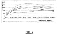
- a plurality of possible examples of such graphical curves is shown in figure 2 , wherein the X-axis shows the angle ⁇ of the lid 10 (called “opening angle tailgate” in figure 2 ) given in degrees and the Y-axis shows the manual operational force F H (denoted by "handle effort" in figure 2 ) given in Newton.
- an output unit 24 When a specific manual operational force F H is selected in dependence on a specific situation, an output unit 24 outputs the armature voltage u A to the drive unit of the actuator 16 such that the drive unit of the actuator 16 generates a supporting torque M depending on the armature voltage u A .
- the dependence of the speed of the drive unit of the actuator 16 on the armature voltage u A resulting in a specific torque M is shown in figure 3 .
- the X-axis describes the speed n of the drive unit of the actuator 16 and the Y-axis describes the torque M generated by the actuator 16.
- the inclined lines running from upper left to lower right of the diagram show different motor characteristics at different armature voltages u 1 (lower/left dashed line), u 2 (solid line) and u 3 (upper/right dashed line), wherein u 1 ⁇ u 2 ⁇ u 3 .
- the arrow pointing from the motor characteristic of u 1 to the motor characteristic of u 3 indicates that increasing the armature voltage u A at a constant speed n of the drive unit of the actuator 16 results in an increased torque M.
- the supporting forces generated by the actuator 16 according to the present invention may be increased or reduced by increasing or reducing an armature voltage u A at the drive unit of the actuator 16, as desired.
Abstract
Description
- The invention relates to an operational force support device that is adapted to support a user when operating a lid. The invention further relates to a method for adjusting a force that has to be applied by a user to operate a lid. Furthermore, the invention relates to a computer module adapted to output an amplification factor and/or an armature voltage that is/are used in the method according to the invention.
- A situation in which a lid has to be operated by a user is, for example, a trunk lid of a vehicle in order to get access to or close the trunk of the vehicle. As this example is of particular importance for the applicant of the present invention, the present invention is described in the following with respect to a trunk lid that is articulated on a vehicle body of a vehicle, e.g. a car. Also, only one or a plurality of actuators may be coupled to a lid. In the following, the present invention is described referring to only one actuator. It is to be understood that the scope of the present invention is not limited to this example by any means.
- Prior art lids often comprise actuators including a drive unit that are adapted to actuate the lid with respect to the vehicle body. Usually, these actuators are adapted to actuate the lid automatically, e.g. without the need of manual assistance by a user.
- In order to retain the lid in any desired position within the complete movement range of the lid, these actuators require passive elements, such as coil springs or brakes. The required forces to retain the lid in the desired position, and therefore the selection of these passive elements, may depend on the weight of the lid and the center of gravity of the lid.
- Sometimes, a user needs to move the lid by hand without activating the actuator. Based on e.g. the selection of the passive elements, the weight of the lid, the center of gravity of the lid, and frictional forces in the hinge of the lid, a user has to apply a certain amount of manual forces when moving the lid by hand.
- In prior art systems these forces are preset once when manufacturing the vehicle and may not be adapted afterwards on an individual level.
- It is therefore an object of the present invention to provide an operational force support device adapted to support a user in moving the lid, and adapted to allow an adjustment of the operational forces after the manufacturing of the vehicle.
- This object is solved by the present invention by providing an operational force support device, comprising an actuator that comprises a drive unit, a lid that the actuator is coupled to, and a unit to which the lid is linked in a movable manner, wherein the actuator is adapted to actuate the lid with respect to the unit that the lid is linked to, a detection unit that the actuator is connected to and that is adapted to detect a speed of the drive unit of the actuator, while the lid is manually operated, and an angle that the lid is situated in with respect to the unit that the lid is linked to, a determination unit that the detection unit is connected to and that is adapted to determine an armature voltage, at which the drive unit of the actuator shall be actuated, in dependence on the speed of the drive unit of the actuator and the angle of the lid with respect to the unit that the lid is linked to or to determine an amplification factor in dependence on the speed of the drive unit of the actuator and the angle of the lid with respect to the unit that the lid is linked to, based on which the armature voltage is determined, and an output unit that is connected to the determination unit and that is adapted to output the armature voltage to the drive unit of the actuator such that the drive unit of the actuator generates a supporting torque depending on the armature voltage.
- Hence, by moving the drive unit passively, i.e. by driving the drive unit due to a manual movement of the lid, the detection unit detects the speed of the drive unit of the actuator. Based on the detected speed of the drive unit and an angle of the lid with respect to the vehicle body, which is also detected by the detection unit, the determination unit is able to determine the armature voltage based on a preset of operational supporting forces that support the movement of the lid by a user and thus reduces the operational forces that a user has to apply in order to move the lid.
- The device may be adjusted in a way that the operational force support device actuates the actuator in dependence on the angle of the lid with respect to the vehicle body such that the manual force that the user has to apply to move the lid is constant over the complete range of movement of the lid and such that the movement of the lid requires the user to apply different manual forces in dependence of the angle of the lid with respect to the vehicle body to move the lid.
- When the operational force support device already actuates the actuator in order to support a user in moving the lid, the drive unit of the actuator is driven with a certain speed based on an armature voltage applied to the drive unit. The speed of the drive unit which is caused by an armature voltage applied to the drive unit in order to support the user in moving the lid and not by the user itself has to be taken into account when performing a further iteration of determining supporting forces. In this case, determining the armature voltage which shall be applied to the drive unit of the actuator comprises
- determining the speed the drive unit is already driven by the operational force support device, e.g. due to an applied armature voltage based on a previous supporting action,
- determining the actual speed that the drive unit is driven by detecting this speed by the detection unit, and
- determining the preset manual operational force that a user is intended to apply to the lid in dependence on the angle that the lid is currently situated in.
- The operational forces may be calculated based on a torque, which is applied by the actuator based on the speed of the drive unit of the actuator and the armature voltage applied to the drive unit of the actuator, and on a preset torque that a user is intended to apply in order to move the lid in dependence on the angle of the lid with respect to the vehicle body.
- If the sum of the speed/torque of the actuator resulting from the actuation of the actuator by the operational force support device and the speed/torque of the actuator that is desired as manual operational force based on a preset is lower than an actual detected speed/torque of the actuator, the operational force support device has to increase the armature voltage in order to reduce the manual operational forces applied by a user to the desired level when moving the lid at a specific angle and velocity with respect to the vehicle body.
- It is to be noted at this point that, based on the geometry of the vehicle body, the lid, and the actuator, the actuator may have to be driven at different speeds in dependence of the angle of the lid with respect to the vehicle body in order to move the lid with a constant velocity over the complete range of movement of the lid.
- Advantageously, the supporting torque generated by the drive unit of the actuator may be below a torque that is necessary to move the lid at the detected speed solely by the drive unit of the actuator. Therefore, to move the lid, an additional torque has to be applied by the user manually. It may thus be prevented that the actuator moves the lid on its own but always requires manual operational forces applied by a user in order to move the lid.
- In an embodiment of the present invention, the operational force support device may further comprise a temperature sensor adapted to detect temperature in the vicinity of the actuator and/or an inclination sensor adapted to detect an angle that the unit that the lid is linked to is situated in with respect to the gravity direction. Both the temperature in the vicinity of the actuator and the inclination of the vehicle body may affect a torque that is needed to move the lid in dependence on the angle of the lid with respect to the vehicle body.
- The detected temperature and/or the detected inclination of the vehicle body may then be taken into account by the determination unit when determining the armature voltage or the amplification factor, respectively.
- In an embodiment of the present invention, the operational force support device may further comprise a storage unit in which a look-up table is stored comprising specific values of armature voltages and/or amplification factors in dependence on at least the angle of the lid with respect to the unit that the lid is linked to, i.e. the vehicle body. This may allow to simply choose a specific value in dependence on at least the angle of the lid instead of calculating it. This may reduce the complexity of the system and the calculation effort of the operational force support device. The look-up table may also take into account the temperature in the vicinity of the actuator and/or the inclination of the vehicle body with respect to the gravity direction and/or a velocity in which the lid is moved.
- In an embodiment of the present invention the actuator may be a linear spindle drive. Linear spindle drives are most common in the application field of moving trunk lids of a vehicle. Of course, the operational force support device and/or the method according to the present invention may be implemented in all kinds of actuators, e.g. rotary drives, linear drives, scissor drives, hydraulic drives, pneumatic drives, and the like.
- In a second aspect, the present invention relates to a method for adjusting a force that has to be applied by a user to operate a lid, wherein an actuator that is adapted to actuate the lid is coupled to the lid, wherein the method comprises: providing the lid, on which the actuator is disposed, detecting the speed of a drive unit of the actuator, while the lid is manually operated, and an angle that the lid is situated in with respect to a unit that the lid is linked to, determining an amplification factor in dependence on the speed of the drive unit of the actuator and the angle of the lid with respect to the unit that the lid is linked to, determining an armature voltage at which the drive unit of the actuator shall be actuated, outputting the armature voltage to the drive unit of the actuator such that the drive unit of the actuator generates a supporting torque depending on the armature voltage.
- It shall be mentioned already at this point that all features and advantages described with respect to the operational force support device may also be applied to the method for adjusting a force according to the present invention, and vice versa.
- As described with respect to the operational force support device, the method according to the present invention allows an adjustment of a manual force that has to be applied by a user to operate a lid of a vehicle by comparing the current speed or torque of the actuator with a predetermined torque or force, i.e. a presetting of manual operational forces, a user is intended to apply in order to move the lid.
- As this presetting of forces may merely be based on values of an algorithm and not on a hardware setup, the forces that have to be applied by a user may be adjusted at any time after the manufacturing of the vehicle by adjusting these values.
- The amplification factor based on which the armature voltage is determined using the formula

- Advantageously, the supporting torque generated by the drive unit of the actuator may be below a torque unit that is necessary to move the lid at the detected speed solely by the drive unit of the actuator. In doing so, the actuator is not capable of actuating the lid on its own but always requires additional manual operational forces applied by a user in order to move the lid. The actuator may here be understood as a pure supporting device.
- The method according to the present invention may further comprise detecting an angle that the unit to which the lid is connected is situated in with respect to the gravity direction. That is, detecting an inclination of the vehicle body that the lid is linked to. Since the torque that is needed to move the lid is different in dependence on the angle of the lid with respect to the vehicle body, due to correspondingly changing leverage forces of the center of gravity of the lid to an articulation point of the lid on the vehicle body, an inclination of the vehicle body may affect this leverage and thus the torque that is needed to move the lid in dependence on the angle of the lid.
- Furthermore, the method according to the present invention may further comprise detecting a temperature in the vicinity of the actuator. Since the components of the actuator may shrink or expand due to temperature changes and/or the friction between components that move relatively to each other may change due to temperature changes, the temperature in the vicinity of the actuator may be taken into account when determining the torque that has to be applied by the user in order to move the lid, i.e. when determining the armature voltage that is to be applied to the drive unit of the actuator in order to support the user in moving the lid.
- Advantageously, determining an amplification factor may comprise selecting a value from a look-up table in dependence on at least the angle of the lid with respect to the unit that the lid is linked to, i.e. the vehicle body. By simply choosing an amplification factor from a plurality of values within the look-up table, the process of determining the amplification factor may be less complex compared to calculating the amplification factor using formulas and equations.
- In addition or as an alternative, determining an armature voltage at which a drive unit of the actuator shall be actuated may comprise selecting a value from a look-up table in dependence on at least the speed of the drive unit of the actuator and the amplification factor. As described above, the amplification factor may also be selected from a look-up table. Also, instead of or in addition to the speed of the drive unit, the torque that is generated by the drive unit may be considered when selecting the value from the look-up table. This may further reduce the complexity or the calculation effort according to the present invention.
- The amplification factor and/or the armature voltage may be selected based on a presetting that defines a specific operation force in dependence on at least the lid angle. This presetting may for example be adjusted by a user, by a manufacturer of the vehicle, by a distributer of the vehicle, by a service provider for the vehicle or the like. The presetting may comprise a specific manual operation force that a user has to apply to move the lid for each angle of the lid with respect to the vehicle body or at least a plurality of value-angle-correlations, e.g. a value for every 1°.
- The method and the operational force support device, respectively, may be adapted to interpolate operational forces for angles of the lid with respect to the vehicle body that lie between two given angles of the presetting. In addition or as an alternative, the presetting may comprise a graphical curve that defines the operation force in dependence on the angle of the lid.
- The presetting may be adjusted or input via a human-machine-interface.
- As stated at the beginning of the description of the present invention, the lid may be a trunk lid of a vehicle adapted to grant or prevent access to the trunk of the vehicle. It shall be noted again that the present invention is not limited to lids that close a container or space, but the term "lid" shall be understood as an actuated part that is coupled to another part in a movable manner, e.g. windows, doors etc.
- In a further aspect, the present invention relates to a computer module adapted to output an amplification factor and/or an armature voltage that is/are used in the method according to the present invention described above based on an input, performed by a user, of a manual operation force of a lid in dependence of an angle of the lid with respect to a unit that the lid is linked to, i.e. a vehicle body. The computer module according to the present invention may comprise at least some of the features described above and may comprise a storage unit containing the above-mentioned look-up table.
- A user of the computer module may input a desired manual operational force, i.e. a presetting of manual operational forces/torques required to move the lid in dependence on the angle of the lid with respect to the vehicle body. The computer module may control the torque generated by the actuator by outputting a specific armature voltage to the drive unit of the actuator based on the detected speed of the drive unit and an angle of the lid and/or a temperature in the vicinity of the actuator and/or an inclination of the vehicle body.
- Advantageously, the input may comprise a graphical curve that defines the operation force in dependence on the angle of the lid. By defining a graphical curve of operational forces in dependence on specific angles of the lid with respect to the vehicle body, the user of the computer module may adjust the presetting of the operational forces that are required for a user of the lid to move the lid using a graphic user interface (GUI). This may provide an intuitive way for the user of the computer module to adjust the presetting of manual operational forces.
- In the following the present invention will be described with respect to the attached drawings, in which:
- Figure 1
- shows a rear part of a vehicle including applied forces and leverages;
- Figure 2
- shows a plurality of graphical curves of operational forces in dependence of angles of the lid;
- Figure 3
- shows a diagram illustrating the correlation of speed of a drive unit of an actuator, armature voltage and generated torque.
- In
figure 1 atrunk lid 10 is articulated on avehicle body 12 at apivot point 14. At the center of gravity of the lid 10 a gravity force FG is applied to thelid 10 with a leverage IFG of the gravity force FG to thepivot point 14. - An
actuator 16 is coupled on its one end to thelid 10 and to thevehicle body 12 on its other end. Infigure 1 only oneactuator 16 is shown but it is to be understood that a second actuator may be disposed on the other longitudinal side of thevehicle body 12. Of course, in case of a plurality of actuators, the supporting forces have to be distributed to the actuators accordingly. A leverage of the coupling point of theactuator 16 at thelid 10 to thepivot point 14 is described by the distance ISD. - An angle of the
lid 10 with respect to thevehicle body 12 is denoted infigure 1 by an angle α. - Furthermore, a force FH that has to be applied by a user in order to move the
lid 10 with respect to thevehicle body 12 is shown at ahandle point 18 at thelid 10. The distance of thehandle point 18 to thepivot point 14 is indicated by the radius RFH. - When a user moves the
lid 10 in the direction of the arrow FH at thehandle point 18 of thelid 10, theactuator 16, which is a linear spindle drive in the shown embodiment, is reduced in length. This results in a rotation of a spindle or a spindle nut, whichever is driven by the drive unit of the spindle drive, and therefore in a passive activation of the drive unit, e.g. in a rotation of a drive shaft of an electric motor. A speed n generated in the drive unit, i.e. here in the electric motor, is detected by adetection unit 20. Thedetection unit 20 also detects the angle α of thelid 10 with respect to thevehicle body 12, e.g. by using corresponding sensors. - The detected speed n of the drive unit of the actuator and the detected angle α of the
lid 10 are forwarded to a determination unit 22 that is adapted to determine an armature voltage uA at which the drive unit of the actuator shall be actuated in dependence of the speed n of the drive unit of the actuator and the angle α of thelid 10. The determination unit 22 may also determine an amplification factor K based on which the armature voltage uA is determined using the formula
- The determination unit 22 may comprise a look-up table including a presetting of values of manual operational forces FH in dependence on angles α of the
lid 10 with respect to thevehicle body 12. This presetting may comprise a graphical curve indicating a manual operational force FH for each angle α of thelid 10. A plurality of possible examples of such graphical curves is shown infigure 2 , wherein the X-axis shows the angle α of the lid 10 (called "opening angle tailgate" infigure 2 ) given in degrees and the Y-axis shows the manual operational force FH (denoted by "handle effort" infigure 2 ) given in Newton. - When a specific manual operational force FH is selected in dependence on a specific situation, an output unit 24 outputs the armature voltage uA to the drive unit of the
actuator 16 such that the drive unit of theactuator 16 generates a supporting torque M depending on the armature voltage uA. - Changing the armature voltage uA at a constant speed n of the drive unit of the
actuator 16, e.g. increasing it, results in a changed, e.g. increased, torque M of theactuator 16. - The dependence of the speed of the drive unit of the
actuator 16 on the armature voltage uA resulting in a specific torque M is shown infigure 3 . The X-axis describes the speed n of the drive unit of theactuator 16 and the Y-axis describes the torque M generated by theactuator 16. The inclined lines running from upper left to lower right of the diagram show different motor characteristics at different armature voltages u1 (lower/left dashed line), u2 (solid line) and u3 (upper/right dashed line), wherein u1 < u2 < u3. - The arrow pointing from the motor characteristic of u1 to the motor characteristic of u3 indicates that increasing the armature voltage uA at a constant speed n of the drive unit of the
actuator 16 results in an increased torque M. - As a result, the supporting forces generated by the
actuator 16 according to the present invention may be increased or reduced by increasing or reducing an armature voltage uA at the drive unit of theactuator 16, as desired.
Claims (15)
- Operational force support device, comprising
an actuator (16) that comprises a drive unit, a lid (10) that the actuator (16) is coupled to, and a unit (12) to which the lid (10) is linked in a movable manner, and wherein the actuator (16) is adapted to actuate the lid (10) with respect to the unit (12) that the lid (10) is linked to,
a detection unit (20) that the actuator (16) is connected to and that is adapted to detect a speed (n) of the drive unit of the actuator (16), while the lid (10) is manually operated, and an angle (a) that the lid (10) is situated in with respect to the unit (12) that the lid (10) is linked to,
a determination unit (22) that the detection unit (20) is connected to and that is adapted to determine an armature voltage (uA), at which the drive unit of the actuator (16) shall be actuated, in dependence on the speed (n) of the drive unit of the actuator (16) and the angle (α) of the lid (10) with respect to the unit (12) that the lid (10) is linked to or to determine an amplification factor (K) in dependence on the speed (n) of the drive unit of the actuator (16) and the angle (a) of the lid (10) with respect to the unit (12) that the lid (10) is linked to, based on which the armature voltage (uA) is determined, and
an output unit (24) that is connected to the determination unit (22) and that is adapted to output the armature voltage (uA) to the drive unit of the actuator (16) such that the drive unit of the actuator (16) generates a supporting torque (M) depending on the armature voltage (uA). - Operational force support device according to claim 1,
wherein the supporting torque (M) generated by the drive unit of the actuator (16) is below a torque that is necessary to move the lid (10) at the detected speed (n) solely by the drive unit of the actuator (16). - Operational force support device according to claim 1 or 2,
wherein the operational force support device further comprises a temperature sensor adapted to detect a temperature in the vicinity of the actuator (16) and/or an inclination sensor adapted to detect an angle that the unit (12) that the lid (10) is linked to is situated in with respect to the gravity direction (FG). - Operational force support device according to any of claims 1 to 3,
wherein the operational force support device further comprises a storage unit in which a look-up table is stored comprising specific values of armature voltages (uA) and/or amplification factors (K) in dependence on at least the angle (α) of the lid (10) with respect to the unit (12) that the lid (10) is linked to. - Operational force support device according to any of claims 1 to 4,
wherein the actuator (16) is a linear spindle drive. - Method for adjusting a force (FH) that has to be applied by a user to operate a lid (10), wherein an actuator (16) that is adapted to actuate the lid (10) is coupled to the lid (10), wherein the method comprises:- providing the lid (10), on which the actuator (16) is disposed,- detecting the speed (n) of a drive unit of the actuator (16), while the lid (10) is manually operated, and an angle (a) that the lid (10) is situated in with respect to a unit (12) that the lid (10) is linked to,- determining an amplification factor (K) in dependence on the speed (n) of the drive unit of the actuator (16) and the angle (α) of the lid (10) with respect to the unit (12) that the lid (10) is linked to,- determining an armature voltage (uA) at which the drive unit of the actuator (16) shall be actuated,- outputting the armature voltage (uA) to the drive unit of the actuator (16) such that the drive unit of the actuator (16) generates a supporting torque (M) depending on the armature voltage (uA).
- Method according to claim 6,
wherein the supporting torque (M) generated by the drive unit of the actuator (16) is below a torque that is necessary to move the lid (10) at the detected speed (n) solely by the drive unit of the actuator (16). - Method according to claim 6 or 7,
wherein the method further comprises:- detecting an angle that the unit (12) to which the lid (10) is connected to is situated in with respect to the gravity direction (FG). - Method according to any of claims 6 to 8,
wherein the method further comprises:- detecting a temperature in the vicinity of the actuator (16). - Method according to any of claims 6 to 9,
wherein determining an amplification factor (K) comprises selecting a value from a look-up table in dependence on at least the angle (α) of the lid (10) with respect to the unit (12) that the lid (10) is linked to. - Method according to any of claims 6 to 10,
wherein determining an armature voltage (uA) at which the drive unit of the actuator (16) shall be actuated comprises selecting a value from a look-up table in dependence on at least the speed (n) of the drive unit of the actuator (16) and the amplification factor (K). - Method according to any of claims 6 to 11,
wherein the amplification factor (K) and/or the armature voltage (uA) is/are selected based on a presetting that defines a specific operation force (FH) in dependence on at least the lid (10) angle (α). - Method according to any of claims 6 to 12,
wherein the lid (10) is a trunk lid (10) of a vehicle adapted to grant or
prevent access to the trunk of the vehicle. - Computer module adapted to output an amplification factor (K) and/or an armature voltage (uA) that is/are used in the method according to any of claims 1 to 9 based on an input, performed by a user, of a manual operation force (FH) of a lid (10) in dependence on an angle (α) of the lid (10) with respect to a unit (12) that the lid (10) is linked to.
- Computer module according to claim 14,
wherein the input comprises a graphical curve that defines the operation force (FH) in dependence on the angle (α) of the lid (10).
Applications Claiming Priority (1)
| Application Number | Priority Date | Filing Date | Title |
|---|---|---|---|
| US201862685464P | 2018-06-15 | 2018-06-15 |
Publications (1)
| Publication Number | Publication Date |
|---|---|
| EP3581749A1 true EP3581749A1 (en) | 2019-12-18 |
Family
ID=66912553
Family Applications (1)
| Application Number | Title | Priority Date | Filing Date |
|---|---|---|---|
| EP19179701.8A Withdrawn EP3581749A1 (en) | 2018-06-15 | 2019-06-12 | Method for adjusting a force that has to be applied by a user to operate a lid |
Country Status (5)
| Country | Link |
|---|---|
| US (1) | US11619089B2 (en) |
| EP (1) | EP3581749A1 (en) |
| JP (1) | JP7018412B2 (en) |
| KR (1) | KR102639018B1 (en) |
| CN (1) | CN110607969B (en) |
Cited By (1)
| Publication number | Priority date | Publication date | Assignee | Title |
|---|---|---|---|---|
| WO2020165187A1 (en) * | 2019-02-11 | 2020-08-20 | Inventus Engineering Gmbh | Assembly and method |
Citations (3)
| Publication number | Priority date | Publication date | Assignee | Title |
|---|---|---|---|---|
| DE102007062473A1 (en) * | 2007-12-20 | 2009-07-02 | Technische Universität München | Door i.e. vehicle door, has actuators provided in operative connection with sensor devices, and kinematics degrees of freedom assigned to actuators for motor support of opening and/or closing motion and/or unlocking-or locking process |
| US20130024076A1 (en) * | 2011-07-19 | 2013-01-24 | Aisin Seiki Kabushiki Kaisha | Vehicle opening-and-closing member control device |
| EP3153651A1 (en) * | 2014-06-05 | 2017-04-12 | Mitsui Kinzoku ACT Corporation | Power door opening and closing device |
Family Cites Families (13)
| Publication number | Priority date | Publication date | Assignee | Title |
|---|---|---|---|---|
| US6755458B1 (en) * | 2000-09-29 | 2004-06-29 | Intier Automotive Closures Inc. | Liftgate force control |
| DE10331633A1 (en) * | 2003-07-12 | 2005-02-03 | Valeo Sicherheitssysteme Gmbh | Drive for automatically actuating a vehicle door |
| JP4289218B2 (en) | 2004-05-25 | 2009-07-01 | 三菱自動車工業株式会社 | Electric tailgate device |
| JP4910498B2 (en) * | 2006-06-20 | 2012-04-04 | アイシン精機株式会社 | Control device for vehicle opening / closing body |
| US8234046B2 (en) * | 2009-02-25 | 2012-07-31 | Rs Drawings, Llc | Method and apparatus for selectively activated powered actuation of a hydraulic drive system |
| CN201896528U (en) * | 2010-11-19 | 2011-07-13 | 宁波信泰机械有限公司 | Electric control device for automobile electric tail gate |
| JP6303212B2 (en) * | 2013-10-08 | 2018-04-04 | 三井金属アクト株式会社 | Open / close control device for vehicle door |
| EP2860704B1 (en) | 2013-10-10 | 2016-04-27 | U-Shin France SAS | Method for opening a movable panel of the motor vehicle and corresponding opening control device |
| JP6203684B2 (en) * | 2014-07-10 | 2017-09-27 | 三井金属アクト株式会社 | Clutchless power door opening and closing device |
| JP6396713B2 (en) * | 2014-08-01 | 2018-09-26 | シロキ工業株式会社 | Opening and closing body drive control device |
| JP6145444B2 (en) * | 2014-12-18 | 2017-06-14 | アイシン精機株式会社 | Control device for vehicle opening / closing body |
| US10094159B2 (en) * | 2016-05-24 | 2018-10-09 | Ford Global Technologies Llc | Power closure panel system performance optimizer |
| JP7056090B2 (en) * | 2017-11-10 | 2022-04-19 | 株式会社アイシン | Vehicle open / close body control device |
-
2019
- 2019-04-16 JP JP2019078103A patent/JP7018412B2/en active Active
- 2019-06-05 US US16/432,456 patent/US11619089B2/en active Active
- 2019-06-11 KR KR1020190068697A patent/KR102639018B1/en active IP Right Grant
- 2019-06-12 EP EP19179701.8A patent/EP3581749A1/en not_active Withdrawn
- 2019-06-14 CN CN201910517078.3A patent/CN110607969B/en active Active
Patent Citations (3)
| Publication number | Priority date | Publication date | Assignee | Title |
|---|---|---|---|---|
| DE102007062473A1 (en) * | 2007-12-20 | 2009-07-02 | Technische Universität München | Door i.e. vehicle door, has actuators provided in operative connection with sensor devices, and kinematics degrees of freedom assigned to actuators for motor support of opening and/or closing motion and/or unlocking-or locking process |
| US20130024076A1 (en) * | 2011-07-19 | 2013-01-24 | Aisin Seiki Kabushiki Kaisha | Vehicle opening-and-closing member control device |
| EP3153651A1 (en) * | 2014-06-05 | 2017-04-12 | Mitsui Kinzoku ACT Corporation | Power door opening and closing device |
Cited By (1)
| Publication number | Priority date | Publication date | Assignee | Title |
|---|---|---|---|---|
| WO2020165187A1 (en) * | 2019-02-11 | 2020-08-20 | Inventus Engineering Gmbh | Assembly and method |
Also Published As
| Publication number | Publication date |
|---|---|
| KR102639018B1 (en) | 2024-02-22 |
| JP7018412B2 (en) | 2022-02-10 |
| CN110607969B (en) | 2022-06-07 |
| US20190381871A1 (en) | 2019-12-19 |
| US11619089B2 (en) | 2023-04-04 |
| JP2020029765A (en) | 2020-02-27 |
| CN110607969A (en) | 2019-12-24 |
| KR20190142221A (en) | 2019-12-26 |
Similar Documents
| Publication | Publication Date | Title |
|---|---|---|
| EP1927526B1 (en) | Electric steering apparatus | |
| US20180328097A1 (en) | Electrical power assisted manually operated door | |
| JP5345736B2 (en) | Method and apparatus for confirming coupling dissociation in a flap drive | |
| GB2543386B (en) | Power system vehicle doors | |
| US20090007489A1 (en) | Vehicle Door Comprising a Deceleration Function | |
| JP2009514720A (en) | Vehicle adjustment mechanism and control device | |
| JP4537428B2 (en) | Opening and closing body control device | |
| US11619089B2 (en) | Method for adjusting a force that has to be applied by a user to operate a lid | |
| WO2011052152A1 (en) | Caught object detection method, setting method for caught object detection device, caught object detection device, and open/close control device | |
| EP2610692A2 (en) | System and method for controlling power trunk | |
| EP3334883B1 (en) | Assistance system for vehicle door | |
| EP3770718A1 (en) | Input device | |
| WO2017029235A1 (en) | Vehicle door | |
| CN113062668B (en) | Apparatus and method for closing door | |
| JP2008095407A (en) | Door operation assist unit | |
| JP2010053529A (en) | Apparatus for controlling electrically-driven door | |
| US20220195782A1 (en) | Opening and closing body control apparatus | |
| JP6864662B2 (en) | Mobile device | |
| JP4678475B2 (en) | Electric motor control device | |
| CN116480242A (en) | Deceleration actuator for electric door of automobile, control method of deceleration actuator and automobile | |
| JP2008214923A (en) | Door opening/closing assist device | |
| JP2007077694A (en) | Safety device of sliding door for vehicle |
Legal Events
| Date | Code | Title | Description |
|---|---|---|---|
| PUAI | Public reference made under article 153(3) epc to a published international application that has entered the european phase |
Free format text: ORIGINAL CODE: 0009012 |
|
| STAA | Information on the status of an ep patent application or granted ep patent |
Free format text: STATUS: THE APPLICATION HAS BEEN PUBLISHED |
|
| AK | Designated contracting states |
Kind code of ref document: A1 Designated state(s): AL AT BE BG CH CY CZ DE DK EE ES FI FR GB GR HR HU IE IS IT LI LT LU LV MC MK MT NL NO PL PT RO RS SE SI SK SM TR |
|
| AX | Request for extension of the european patent |
Extension state: BA ME |
|
| STAA | Information on the status of an ep patent application or granted ep patent |
Free format text: STATUS: REQUEST FOR EXAMINATION WAS MADE |
|
| 17P | Request for examination filed |
Effective date: 20200617 |
|
| RBV | Designated contracting states (corrected) |
Designated state(s): AL AT BE BG CH CY CZ DE DK EE ES FI FR GB GR HR HU IE IS IT LI LT LU LV MC MK MT NL NO PL PT RO RS SE SI SK SM TR |
|
| STAA | Information on the status of an ep patent application or granted ep patent |
Free format text: STATUS: EXAMINATION IS IN PROGRESS |
|
| STAA | Information on the status of an ep patent application or granted ep patent |
Free format text: STATUS: EXAMINATION IS IN PROGRESS |
|
| 17Q | First examination report despatched |
Effective date: 20201221 |
|
| RIN1 | Information on inventor provided before grant (corrected) |
Inventor name: SABET, DAVE Inventor name: KNOPP, MICHAEL |
|
| P01 | Opt-out of the competence of the unified patent court (upc) registered |
Effective date: 20230517 |
|
| STAA | Information on the status of an ep patent application or granted ep patent |
Free format text: STATUS: THE APPLICATION HAS BEEN WITHDRAWN |
|
| 18W | Application withdrawn |
Effective date: 20230907 |