EP3581690A1 - Fiber structure and fiber reinforced composite material - Google Patents
Fiber structure and fiber reinforced composite material Download PDFInfo
- Publication number
- EP3581690A1 EP3581690A1 EP18751594.5A EP18751594A EP3581690A1 EP 3581690 A1 EP3581690 A1 EP 3581690A1 EP 18751594 A EP18751594 A EP 18751594A EP 3581690 A1 EP3581690 A1 EP 3581690A1
- Authority
- EP
- European Patent Office
- Prior art keywords
- fabric
- yarns
- fiber structure
- fixing portions
- outermost
- Prior art date
- Legal status (The legal status is an assumption and is not a legal conclusion. Google has not performed a legal analysis and makes no representation as to the accuracy of the status listed.)
- Withdrawn
Links
- 239000000835 fiber Substances 0.000 title claims abstract description 113
- 239000000463 material Substances 0.000 title claims description 29
- 239000003733 fiber-reinforced composite Substances 0.000 title claims description 22
- 239000004744 fabric Substances 0.000 claims abstract description 120
- 238000003475 lamination Methods 0.000 claims abstract description 25
- 229920005989 resin Polymers 0.000 claims description 19
- 239000011347 resin Substances 0.000 claims description 19
- 239000011159 matrix material Substances 0.000 claims description 18
- 238000004080 punching Methods 0.000 claims description 14
- 239000012783 reinforcing fiber Substances 0.000 claims description 13
- 230000003014 reinforcing effect Effects 0.000 claims description 5
- 239000010410 layer Substances 0.000 description 17
- 238000000034 method Methods 0.000 description 5
- 230000002411 adverse Effects 0.000 description 3
- 239000011230 binding agent Substances 0.000 description 3
- 238000004519 manufacturing process Methods 0.000 description 3
- 230000000694 effects Effects 0.000 description 2
- 238000005470 impregnation Methods 0.000 description 2
- 239000012784 inorganic fiber Substances 0.000 description 2
- 238000010030 laminating Methods 0.000 description 2
- -1 poly(p-phenylenebenzobisoxazole) Polymers 0.000 description 2
- 239000002356 single layer Substances 0.000 description 2
- 238000009732 tufting Methods 0.000 description 2
- 238000009941 weaving Methods 0.000 description 2
- 229920000049 Carbon (fiber) Polymers 0.000 description 1
- 239000004699 Ultra-high molecular weight polyethylene Substances 0.000 description 1
- 239000004760 aramid Substances 0.000 description 1
- 229920006231 aramid fiber Polymers 0.000 description 1
- 239000004917 carbon fiber Substances 0.000 description 1
- 239000000919 ceramic Substances 0.000 description 1
- 239000003822 epoxy resin Substances 0.000 description 1
- 239000003365 glass fiber Substances 0.000 description 1
- 238000012986 modification Methods 0.000 description 1
- 230000004048 modification Effects 0.000 description 1
- 229920000927 poly(p-phenylene benzobisoxazole) Polymers 0.000 description 1
- 229920000647 polyepoxide Polymers 0.000 description 1
- 229920001187 thermosetting polymer Polymers 0.000 description 1
- 238000001721 transfer moulding Methods 0.000 description 1
- 229920000785 ultra high molecular weight polyethylene Polymers 0.000 description 1
- 238000011144 upstream manufacturing Methods 0.000 description 1
Images


Classifications
-
- D—TEXTILES; PAPER
- D03—WEAVING
- D03D—WOVEN FABRICS; METHODS OF WEAVING; LOOMS
- D03D5/00—Selvedges
-
- B—PERFORMING OPERATIONS; TRANSPORTING
- B32—LAYERED PRODUCTS
- B32B—LAYERED PRODUCTS, i.e. PRODUCTS BUILT-UP OF STRATA OF FLAT OR NON-FLAT, e.g. CELLULAR OR HONEYCOMB, FORM
- B32B5/00—Layered products characterised by the non- homogeneity or physical structure, i.e. comprising a fibrous, filamentary, particulate or foam layer; Layered products characterised by having a layer differing constitutionally or physically in different parts
- B32B5/02—Layered products characterised by the non- homogeneity or physical structure, i.e. comprising a fibrous, filamentary, particulate or foam layer; Layered products characterised by having a layer differing constitutionally or physically in different parts characterised by structural features of a fibrous or filamentary layer
- B32B5/024—Woven fabric
-
- B—PERFORMING OPERATIONS; TRANSPORTING
- B32—LAYERED PRODUCTS
- B32B—LAYERED PRODUCTS, i.e. PRODUCTS BUILT-UP OF STRATA OF FLAT OR NON-FLAT, e.g. CELLULAR OR HONEYCOMB, FORM
- B32B5/00—Layered products characterised by the non- homogeneity or physical structure, i.e. comprising a fibrous, filamentary, particulate or foam layer; Layered products characterised by having a layer differing constitutionally or physically in different parts
- B32B5/02—Layered products characterised by the non- homogeneity or physical structure, i.e. comprising a fibrous, filamentary, particulate or foam layer; Layered products characterised by having a layer differing constitutionally or physically in different parts characterised by structural features of a fibrous or filamentary layer
- B32B5/06—Layered products characterised by the non- homogeneity or physical structure, i.e. comprising a fibrous, filamentary, particulate or foam layer; Layered products characterised by having a layer differing constitutionally or physically in different parts characterised by structural features of a fibrous or filamentary layer characterised by a fibrous or filamentary layer mechanically connected, e.g. by needling to another layer, e.g. of fibres, of paper
-
- B—PERFORMING OPERATIONS; TRANSPORTING
- B32—LAYERED PRODUCTS
- B32B—LAYERED PRODUCTS, i.e. PRODUCTS BUILT-UP OF STRATA OF FLAT OR NON-FLAT, e.g. CELLULAR OR HONEYCOMB, FORM
- B32B5/00—Layered products characterised by the non- homogeneity or physical structure, i.e. comprising a fibrous, filamentary, particulate or foam layer; Layered products characterised by having a layer differing constitutionally or physically in different parts
- B32B5/22—Layered products characterised by the non- homogeneity or physical structure, i.e. comprising a fibrous, filamentary, particulate or foam layer; Layered products characterised by having a layer differing constitutionally or physically in different parts characterised by the presence of two or more layers which are next to each other and are fibrous, filamentary, formed of particles or foamed
- B32B5/24—Layered products characterised by the non- homogeneity or physical structure, i.e. comprising a fibrous, filamentary, particulate or foam layer; Layered products characterised by having a layer differing constitutionally or physically in different parts characterised by the presence of two or more layers which are next to each other and are fibrous, filamentary, formed of particles or foamed one layer being a fibrous or filamentary layer
- B32B5/26—Layered products characterised by the non- homogeneity or physical structure, i.e. comprising a fibrous, filamentary, particulate or foam layer; Layered products characterised by having a layer differing constitutionally or physically in different parts characterised by the presence of two or more layers which are next to each other and are fibrous, filamentary, formed of particles or foamed one layer being a fibrous or filamentary layer another layer next to it also being fibrous or filamentary
-
- B—PERFORMING OPERATIONS; TRANSPORTING
- B32—LAYERED PRODUCTS
- B32B—LAYERED PRODUCTS, i.e. PRODUCTS BUILT-UP OF STRATA OF FLAT OR NON-FLAT, e.g. CELLULAR OR HONEYCOMB, FORM
- B32B5/00—Layered products characterised by the non- homogeneity or physical structure, i.e. comprising a fibrous, filamentary, particulate or foam layer; Layered products characterised by having a layer differing constitutionally or physically in different parts
- B32B5/22—Layered products characterised by the non- homogeneity or physical structure, i.e. comprising a fibrous, filamentary, particulate or foam layer; Layered products characterised by having a layer differing constitutionally or physically in different parts characterised by the presence of two or more layers which are next to each other and are fibrous, filamentary, formed of particles or foamed
- B32B5/24—Layered products characterised by the non- homogeneity or physical structure, i.e. comprising a fibrous, filamentary, particulate or foam layer; Layered products characterised by having a layer differing constitutionally or physically in different parts characterised by the presence of two or more layers which are next to each other and are fibrous, filamentary, formed of particles or foamed one layer being a fibrous or filamentary layer
- B32B5/26—Layered products characterised by the non- homogeneity or physical structure, i.e. comprising a fibrous, filamentary, particulate or foam layer; Layered products characterised by having a layer differing constitutionally or physically in different parts characterised by the presence of two or more layers which are next to each other and are fibrous, filamentary, formed of particles or foamed one layer being a fibrous or filamentary layer another layer next to it also being fibrous or filamentary
- B32B5/262—Layered products characterised by the non- homogeneity or physical structure, i.e. comprising a fibrous, filamentary, particulate or foam layer; Layered products characterised by having a layer differing constitutionally or physically in different parts characterised by the presence of two or more layers which are next to each other and are fibrous, filamentary, formed of particles or foamed one layer being a fibrous or filamentary layer another layer next to it also being fibrous or filamentary characterised by one fibrous or filamentary layer being a woven fabric layer
- B32B5/263—Layered products characterised by the non- homogeneity or physical structure, i.e. comprising a fibrous, filamentary, particulate or foam layer; Layered products characterised by having a layer differing constitutionally or physically in different parts characterised by the presence of two or more layers which are next to each other and are fibrous, filamentary, formed of particles or foamed one layer being a fibrous or filamentary layer another layer next to it also being fibrous or filamentary characterised by one fibrous or filamentary layer being a woven fabric layer next to one or more woven fabric layers
-
- D—TEXTILES; PAPER
- D03—WEAVING
- D03D—WOVEN FABRICS; METHODS OF WEAVING; LOOMS
- D03D1/00—Woven fabrics designed to make specified articles
-
- D—TEXTILES; PAPER
- D03—WEAVING
- D03D—WOVEN FABRICS; METHODS OF WEAVING; LOOMS
- D03D11/00—Double or multi-ply fabrics not otherwise provided for
-
- D—TEXTILES; PAPER
- D04—BRAIDING; LACE-MAKING; KNITTING; TRIMMINGS; NON-WOVEN FABRICS
- D04H—MAKING TEXTILE FABRICS, e.g. FROM FIBRES OR FILAMENTARY MATERIAL; FABRICS MADE BY SUCH PROCESSES OR APPARATUS, e.g. FELTS, NON-WOVEN FABRICS; COTTON-WOOL; WADDING ; NON-WOVEN FABRICS FROM STAPLE FIBRES, FILAMENTS OR YARNS, BONDED WITH AT LEAST ONE WEB-LIKE MATERIAL DURING THEIR CONSOLIDATION
- D04H1/00—Non-woven fabrics formed wholly or mainly of staple fibres or like relatively short fibres
- D04H1/40—Non-woven fabrics formed wholly or mainly of staple fibres or like relatively short fibres from fleeces or layers composed of fibres without existing or potential cohesive properties
- D04H1/44—Non-woven fabrics formed wholly or mainly of staple fibres or like relatively short fibres from fleeces or layers composed of fibres without existing or potential cohesive properties the fleeces or layers being consolidated by mechanical means, e.g. by rolling
- D04H1/46—Non-woven fabrics formed wholly or mainly of staple fibres or like relatively short fibres from fleeces or layers composed of fibres without existing or potential cohesive properties the fleeces or layers being consolidated by mechanical means, e.g. by rolling by needling or like operations to cause entanglement of fibres
-
- D—TEXTILES; PAPER
- D06—TREATMENT OF TEXTILES OR THE LIKE; LAUNDERING; FLEXIBLE MATERIALS NOT OTHERWISE PROVIDED FOR
- D06M—TREATMENT, NOT PROVIDED FOR ELSEWHERE IN CLASS D06, OF FIBRES, THREADS, YARNS, FABRICS, FEATHERS OR FIBROUS GOODS MADE FROM SUCH MATERIALS
- D06M17/00—Producing multi-layer textile fabrics
- D06M17/04—Producing multi-layer textile fabrics by applying synthetic resins as adhesives
-
- B—PERFORMING OPERATIONS; TRANSPORTING
- B32—LAYERED PRODUCTS
- B32B—LAYERED PRODUCTS, i.e. PRODUCTS BUILT-UP OF STRATA OF FLAT OR NON-FLAT, e.g. CELLULAR OR HONEYCOMB, FORM
- B32B2260/00—Layered product comprising an impregnated, embedded, or bonded layer wherein the layer comprises an impregnation, embedding, or binder material
- B32B2260/02—Composition of the impregnated, bonded or embedded layer
- B32B2260/021—Fibrous or filamentary layer
- B32B2260/023—Two or more layers
-
- B—PERFORMING OPERATIONS; TRANSPORTING
- B32—LAYERED PRODUCTS
- B32B—LAYERED PRODUCTS, i.e. PRODUCTS BUILT-UP OF STRATA OF FLAT OR NON-FLAT, e.g. CELLULAR OR HONEYCOMB, FORM
- B32B2260/00—Layered product comprising an impregnated, embedded, or bonded layer wherein the layer comprises an impregnation, embedding, or binder material
- B32B2260/04—Impregnation, embedding, or binder material
- B32B2260/046—Synthetic resin
-
- B—PERFORMING OPERATIONS; TRANSPORTING
- B32—LAYERED PRODUCTS
- B32B—LAYERED PRODUCTS, i.e. PRODUCTS BUILT-UP OF STRATA OF FLAT OR NON-FLAT, e.g. CELLULAR OR HONEYCOMB, FORM
- B32B2262/00—Composition or structural features of fibres which form a fibrous or filamentary layer or are present as additives
- B32B2262/02—Synthetic macromolecular fibres
-
- B—PERFORMING OPERATIONS; TRANSPORTING
- B32—LAYERED PRODUCTS
- B32B—LAYERED PRODUCTS, i.e. PRODUCTS BUILT-UP OF STRATA OF FLAT OR NON-FLAT, e.g. CELLULAR OR HONEYCOMB, FORM
- B32B2262/00—Composition or structural features of fibres which form a fibrous or filamentary layer or are present as additives
- B32B2262/02—Synthetic macromolecular fibres
- B32B2262/0253—Polyolefin fibres
-
- B—PERFORMING OPERATIONS; TRANSPORTING
- B32—LAYERED PRODUCTS
- B32B—LAYERED PRODUCTS, i.e. PRODUCTS BUILT-UP OF STRATA OF FLAT OR NON-FLAT, e.g. CELLULAR OR HONEYCOMB, FORM
- B32B2262/00—Composition or structural features of fibres which form a fibrous or filamentary layer or are present as additives
- B32B2262/02—Synthetic macromolecular fibres
- B32B2262/0261—Polyamide fibres
- B32B2262/0269—Aromatic polyamide fibres
-
- B—PERFORMING OPERATIONS; TRANSPORTING
- B32—LAYERED PRODUCTS
- B32B—LAYERED PRODUCTS, i.e. PRODUCTS BUILT-UP OF STRATA OF FLAT OR NON-FLAT, e.g. CELLULAR OR HONEYCOMB, FORM
- B32B2262/00—Composition or structural features of fibres which form a fibrous or filamentary layer or are present as additives
- B32B2262/10—Inorganic fibres
- B32B2262/101—Glass fibres
-
- B—PERFORMING OPERATIONS; TRANSPORTING
- B32—LAYERED PRODUCTS
- B32B—LAYERED PRODUCTS, i.e. PRODUCTS BUILT-UP OF STRATA OF FLAT OR NON-FLAT, e.g. CELLULAR OR HONEYCOMB, FORM
- B32B2262/00—Composition or structural features of fibres which form a fibrous or filamentary layer or are present as additives
- B32B2262/10—Inorganic fibres
- B32B2262/105—Ceramic fibres
-
- B—PERFORMING OPERATIONS; TRANSPORTING
- B32—LAYERED PRODUCTS
- B32B—LAYERED PRODUCTS, i.e. PRODUCTS BUILT-UP OF STRATA OF FLAT OR NON-FLAT, e.g. CELLULAR OR HONEYCOMB, FORM
- B32B2262/00—Composition or structural features of fibres which form a fibrous or filamentary layer or are present as additives
- B32B2262/10—Inorganic fibres
- B32B2262/106—Carbon fibres, e.g. graphite fibres
-
- D—TEXTILES; PAPER
- D10—INDEXING SCHEME ASSOCIATED WITH SUBLASSES OF SECTION D, RELATING TO TEXTILES
- D10B—INDEXING SCHEME ASSOCIATED WITH SUBLASSES OF SECTION D, RELATING TO TEXTILES
- D10B2505/00—Industrial
- D10B2505/02—Reinforcing materials; Prepregs
Definitions
- the present invention relates to a fiber structure made of a multilayer fabric having first yarns and second yarns and a fiber-reinforced composite material using the fiber structure.
- the first yarns and the second yarns are bundles of reinforcing fibers.
- Fiber-reinforced composite materials are widely used as lightweight structural materials.
- a fiber structure is a reinforcing base material for a fiber-reinforced composite material, and the fiber-reinforced composite material formed by combining the fiber structure with resin as a matrix is used as structural materials for airplanes, vehicles, buildings, and the like.
- the fiber structure is made of a multilayer fabric.
- a laminated fabric as a multilayer fabric is formed by, for example, laminating several single-layer fabrics formed by plain weave. In some cases, such laminated several single-layer fabrics are joined with each other in the lamination direction to form the laminated fabrics.
- the fiber structure is carried or shaped, of fabric edges of the fiber structure, for example, one fabric edge in which each ends of warps extending in a yarn main axis direction of the warps are located has a possibility of fraying. Then, wefts extending orthogonally to the warps may be pulled out from the frayed fabric edge.
- tapes are attached to fabric edges of a fiber structure in Patent Document 1.
- Patent Document 1 Japanese Patent Application Publication No. 2002-249957
- Patent Document 1 to prevent the fraying of the fabric edge of the fiber structure, the tapes which are separate members from the fiber structure are needed, increasing costs for manufacturing the fiber structure. Furthermore, the tapes used to prevent the fraying may adversely affect the combining of the fiber structure with a matrix.
- a fiber structure includes a multilayer fabric including first yarns and second yarns arranged orthogonally to the first yarns, the first yarns and the second yarns being bundles of reinforcing fibers.
- the fiber structure includes a first fabric edge of the multilayer fabric wherein ends of the first yarns are located in a yarn main axis direction of the first yarns, a second fabric edge of the multilayer fabric wherein ends of the second yarns are located in a yarn main axis direction of the second yarns, and fabric-style fixing portions disposed in at least one of the first fabric edge and the second fabric edge.
- the fabric-style fixing portions are formed by entangling the reinforcing fibers of yarns of the first yarns and the second yarns overlapped in a lamination direction of the multilayer fabric.
- the fabric-style fixing portions are formed in at least one of an outermost yarn and ends of one of the two types of yarns.
- the outermost yarn is located closest to the ends of the other of the two types of yarns.
- the ends of the one of the two types of yarns are located closer to the ends than the outermost yarn in the yarn main axis direction of the one of the two types of yarns.
- the reinforcing fibers of each yarn overlapped with the outermost yarn in the lamination direction are entangled with each other, thereby preventing pulling out of the outermost yarn from the fabric edge.
- the reinforcing fibers are entangled at a position closer to the ends of the one of the two types of yarns than the outermost yarn in the yarn main axis direction of the one of the two types of yarns, thereby preventing pulling out of the outermost yarn over the ends of the one of the two types of yarns.
- the fabric-style fixing portions may be disposed only in the outermost yarn in the fiber structure.
- the fiber structure does not have the fabric-style fixing portions more inside than the outermost yarn extending in a yarn main axis direction of the one of the two types of yarns. This configuration minimizes twisting of the reinforcing fibers caused by forming the fabric-style fixing portions.
- the first yarns and the second yarns of the fiber structure may be made of discontinuous fibers.
- the discontinuous fibers are entangled in many portions between the yarns overlapped in the lamination direction, thereby effectively preventing the fraying.
- the fiber-reinforced composite material to solve the above issues is formed by impregnating a reinforcing base material made of a fiber structure with matrix resin.
- the aforesaid fiber structure corresponds to the fiber structure according to any one of claims 1 to 3.
- the fabric-style fixing portions prevents the fraying of the fabric edges of the fiber structure.
- the fabric-style fixing portions are formed by entangling the reinforcing fibers of yarns overlapped in the lamination direction. Therefore, no separate members are needed to prevent the fraying in the fabric edges. Therefore, in the fiber-reinforced composite material formed by impregnating the fiber structure with matrix resin, no separating members will adversely affect the combining of the matrix resin.
- a fiber structure and a fiber-reinforced composite material according to an embodiment of the present invention will now be described with reference to FIG. 1 to FIG. 5 .
- a fiber-reinforced composite material 10 is formed by impregnating a reinforcing base material being a fiber structure 11 made of a multilayer fabric with matrix resin Ma.
- matrix resin Ma for example, thermosetting epoxy resin is used.
- the fiber structure 11 is formed by laminating a plurality of fabrics 20.
- each fabric 20 is formed by interlacing a plurality of warps 21 with a plurality of wefts 31, and has a rectangular shape in a plan view.
- the warps 21 and the wefts 31 correspond to first yarns and second yarns, respectively.
- Each fabric 20 is formed by plain weave to interlace the warps 21 and the wefts 31.
- the wefts 31 are arranged orthogonally to the warps 21.
- the warps 21 and the wefts 31 are made of discontinuous fibers 11a.
- Organic fibers and inorganic fibers that are the reinforcing fibers may be used as the discontinuous fibers 11a.
- the organic fibers include aramid fibers, poly(p-phenylenebenzobisoxazole) fibers, ultra-high molecular weight polyethylene fibers, and the like.
- the inorganic fibers include carbon fibers, glass fibers, ceramic fibers, and the like.
- the form of yarn bundles made of the discontinuous fibers 11a includes a spun yarn, a stretch-broken yarn, and the like.
- the direction in which a yarn main axis L1 of the warps 21 extends is defined as the first direction X of the fiber structure 11.
- the direction in which a yarn main axis L2 of the wefts 31 extends, and orthogonal to the first direction X is defined as the second direction Y of the fiber structure 11.
- the plurality of the warps 21 are arranged side by side in the second direction Y of the fiber structure 11 and parallel to each other in the fiber structure 11.
- the plurality of the wefts 31 are arranged side by side in the first direction X of the fiber structure 11 and parallel to each other in the fiber structure 11. Referring to FIG.
- the fabrics 20 overlapped in the lamination direction are configured such that the warps 21 of one fabric 20 overlap with the wefts 31 of the other fabric 20 in the fiber structure 11.
- the one fabric 20 is laminated on the other fabric 20.
- the fabrics 20 overlapped in the lamination direction are bound in the lamination direction by binder yarns (not shown).
- the fiber structure 11 includes opposite first fabric edges 12 of the multilayer fabric where the ends 21a of the warps 21 are located in a yarn main axis direction of the warps 21 (the first direction X).
- the wefts 31 are located more inside than the end 21a of the warps 21 in the first direction X (closer to the center of the fiber structure 11).
- the outermost weft 31 located closest to the ends 21a of the warps 21 and at the outermost side is an outermost weft 32 as the outermost yarn.
- the warps 21 correspond to one of the two types of yarns
- the wefts 31 correspond to the other of the two types of yarns.
- the outermost weft 32 is arranged beside the ends 21a of the warps 21. Therefore, in the first fabric edge 12, the outermost weft 32 is located at a position closer to the center of the fiber structure 11 than the end 21a of the warps 21.
- the fiber structure 11 includes opposite second fabric edges 13 of the multilayer fabric where the ends 31a of the wefts 31 are located in the yarn main axis direction of the wefts 31 (the second direction Y).
- the warps 21 are located more inside than the end 31a of the wefts 31 in the second direction Y (closer to the center of the fiber structure 11).
- the outermost warp 21 located closest to the ends 31a of the wefts 31 and at the outermost side is an outermost warp 22 as the outermost yarn.
- the outermost warp 22 is located at a position closer to the center of the fiber structure 11 than the end 31a of the wefts 31.
- the wefts 31 correspond to the one of the two types of yarns
- the warps 21 correspond to the other of the two types of yarns.
- the outermost warp 22 is arranged beside the ends 31a of the wefts 31.
- the fiber structure 11 includes fabric-style fixing portions 14 in each of the first fabric edges 12 and each of the second fabric edges 13.
- the fabric-style fixing portions 14 disposed in the first fabric edge 12 are formed by needle punching on the outermost weft 32.
- the fabric-style fixing portions 14 disposed in the first fabric edge 12 are formed to entangle the discontinuous fibers 11a of the outermost weft 32 and the warps 21 overlapping the outermost weft 32 in the lamination direction with each other in each fabric 20.
- the fabric-style fixing portions 14 disposed in the first fabric edge 12 are formed to entangle the discontinuous fibers 11a of the outermost weft 32 of the one fabric 20 and the warps 21 of the other fabric 20 with each other between the fabrics 20 overlapped in the lamination direction.
- the fabric-style fixing portions 14 are formed to entangle the discontinuous fibers 11a of the wefts 31 overlapped in the lamination direction with each other, which is not illustrated.
- the fabric-style fixing portions 14 disposed in the second fabric edge 13 are formed by needle punching on the outermost warp 22.
- the fabric-style fixing portions 14 disposed in the second fabric edge 13 are formed to entangle the discontinuous fibers 11a of the outermost warp 22 and the wefts 31 overlapping the outermost warp 22 in the lamination direction with each other in each fabric 20.
- the fabric-style fixing portions 14 disposed in the second fabric edge 13 are formed to entangle the discontinuous fibers 11a of the outermost warp 22 of the one fabric 20 and the wefts 31 of the other fabric 20 with each other between the fabrics 20 overlapped in the lamination direction.
- the fabric-style fixing portions 14 are formed to entangle the discontinuous fibers 11a of the wefts 31 overlapped in the lamination direction with each other, which is not illustrated.
- the discontinuous fibers 11a are twisted and entangled in a complicated manner between the warps 21 and the wefts 31, between the warps 21, and between the wefts 31, overlapped in the lamination direction.
- the warps 21 and the wefts 31 are made of the discontinuous fibers 11a, so that the discontinuous fibers 11a are entangled in many portions at the fabric-style fixing portions 14.
- the fiber structure 11 made of a multilayer fabric configured as described above is impregnated with matrix resin Ma, and then the matrix resin Ma is cured, thereby producing the fiber-reinforced composite material 10.
- the impregnation and the cure of the matrix resin Ma is performed by, for example, RTM (resin transfer molding) method.
- RTM resin transfer molding
- the fabric-style fixing portions 14 disposed in the fiber structure 11 prevent the fraying in the first fabric edge 12 and the second fabric edge 13.
- the warps 21 and the wefts 31 need not necessarily be made of the discontinuous fibers 11a, and may be continuous yarns which are formed by bundling several hundreds to several tens of thousands of continuous fibers.
- a fiber structure 40 may be a multilayer fabric formed by 3D-weave.
- the fiber structure 40 includes warp layers 41, 43, 45 in each of which the warps 21 corresponding to the first yarns are arranged parallel to each other, and weft layers 42, 44, 46 in each of which the wefts 31 corresponding to the second yarns are arranged to each other.
- the fiber structure 40 includes the first warp layer 41, the first weft layer 42, the second warp layer 43, the second weft layer 44, the third warp layer 45, and the third weft layer 46 in this order from top to bottom.
- the first warp layer 41, the first weft layer 42, the second warp layer 43, the second weft layer 44, the third warp layer 45, and the third weft layer 46 are bound by binder yarns 48 in the lamination direction.
- the binder yarns 48 are warps used for holding the shape of the fiber structure 40.
- the fiber structure 40 includes the fabric-style fixing portions 14 in opposite first fabric edges 51 in which the ends 21a of the warps 21 are located in the yarn main axis direction of the warps 21. Furthermore, the fiber structure 40 includes the fabric-style fixing portions 14 in opposite second fabric edges in which the ends 31a of the wefts 31 are located in the yarn main axis direction of the wefts 31, which is not illustrated.
- a plurality of the fabric-style fixing portions 14 may be disposed along the first direction X by needle punching on the wefts 31 which are located more inside than the outermost weft 32 in the first direction X.
- a plurality of the fabric-style fixing portions 14 may be disposed along the second direction Y by needle punching on the warps 21 which are located more inside than the outermost warp 22 in the second direction Y.
- the fabric-style fixing portions 14 may be disposed only in the ends 21a of the warps 21 which are located more outside than the outermost weft 32 in the first direction X.
- the fabric-style fixing portions 14 may be disposed in the ends 21a of the warps 21 that are located closer to the ends than the outermost weft 32 in the yarn main axis direction of the warps 21 corresponding to the one of the two types of yarns (in the first direction X).
- the fabric-style fixing portions 14 may be disposed only in the ends 31a of the wefts 31 which are located more outside than the outermost warp 22 in the second direction Y.
- the fabric-style fixing portions 14 may be disposed in the ends 31a of the wefts 31 that are located closer to the ends than the outermost warp 22 in the yarn main axis direction of the wefts 31 corresponding to the one of the two types of yarns (in the second direction Y).
- the discontinuous fibers 11a are entangled between the warps 21 overlapped in the lamination direction in the ends 21a closer to the ends in the yarn main axis direction of the warps 21 than the outermost weft 32, so that the outermost weft 32 is prevented from being pulling out over the ends 21a of the warps 21.
- the discontinuous fibers 11a are entangled between the wefts 31 overlapped in the lamination direction in the ends 31a closer to the ends in the yarn main axis direction of the wefts 31 than the outermost warp 22, so that the outermost warp 22 is prevented from being pulling out over the end 31a of the wefts 31.
- the fabric-style fixing portions 14 prevent the fraying in the fabric edge 12, 13.
- the fabric-style fixing portions 14 are formed such that the discontinuous fibers 11a are entangled between the warps 21 overlapped in the lamination direction, and between the wefts 31 overlapped in the lamination direction. Therefore, no separate members are needed to prevent the fraying in the fabric edge 12, 13.
- the fabric-style fixing portions 14 may be added by needle punching on the outermost weft 32 in each first fabric edge 12 and on the outermost warp 22 in each second fabric edge 13. Owing to this addition, both the fabric-style fixing portions 14 which are located on the outermost weft 32 and the fabric-style fixing portions 14 which are located on the ends 21a of the warps 21 cooperate to effectively prevent the fraying in the first fabric edge 12. Similar to the first fabric edge 12, both the fabric-style fixing portions 14 which are located on the outermost warp 22 and the fabric-style fixing portions 14 which are located on each end 31a of the wefts 31 cooperate to effectively prevent the fraying in the second fabric edge 13.
- the fabric-style fixing portions 14 may be disposed in only either the first fabric edges 12 and the second fabric edges 13 in the fiber structure 11, and in only either the first fabric edges 51 and the second fabric edges in the fiber structure 40. In this case, the opposite edges on the upstream and downstream sides in the weaving direction of the fiber structures 11, 40 are cut after the fiber structures 11, 40 are completed. Therefore, the fabric-style fixing portions 14 may be disposed only in the cut edges and may not be disposed in the opposite sides in the weaving width direction.
- tufting may be applied. Besides needle punching and tufting, any method may be applied if the reinforcing fibers (the discontinuous fibers 11a) are entangled with each other between adjacent layers.
- the fabrics 20 are formed by plain weave in the above embodiment, the fabrics 20 may be formed by satin weave or twill weave.
- the number of laminated weft layers and warp layers may be changed as required in the fiber structure 40.
- the type of matrix resin and the method for manufacturing the fiber-reinforced composite material 10 are not limited to any particular resin or method.
Landscapes
- Engineering & Computer Science (AREA)
- Textile Engineering (AREA)
- Mechanical Engineering (AREA)
- Woven Fabrics (AREA)
- Reinforced Plastic Materials (AREA)
- Knitting Of Fabric (AREA)
Abstract
Description
- The present invention relates to a fiber structure made of a multilayer fabric having first yarns and second yarns and a fiber-reinforced composite material using the fiber structure. The first yarns and the second yarns are bundles of reinforcing fibers.
- Fiber-reinforced composite materials are widely used as lightweight structural materials. A fiber structure is a reinforcing base material for a fiber-reinforced composite material, and the fiber-reinforced composite material formed by combining the fiber structure with resin as a matrix is used as structural materials for airplanes, vehicles, buildings, and the like. The fiber structure is made of a multilayer fabric.
- A laminated fabric as a multilayer fabric is formed by, for example, laminating several single-layer fabrics formed by plain weave. In some cases, such laminated several single-layer fabrics are joined with each other in the lamination direction to form the laminated fabrics. By the way, when the fiber structure is carried or shaped, of fabric edges of the fiber structure, for example, one fabric edge in which each ends of warps extending in a yarn main axis direction of the warps are located has a possibility of fraying. Then, wefts extending orthogonally to the warps may be pulled out from the frayed fabric edge. To prevent such fraying at the fabric edge of the fiber structure, for example, tapes are attached to fabric edges of a fiber structure in
Patent Document 1. - Patent Document 1: Japanese Patent Application Publication No.
2002-249957 - However, in
Patent Document 1, to prevent the fraying of the fabric edge of the fiber structure, the tapes which are separate members from the fiber structure are needed, increasing costs for manufacturing the fiber structure. Furthermore, the tapes used to prevent the fraying may adversely affect the combining of the fiber structure with a matrix. - It is an objective of the present invention to provide a fiber structure and a fiber-reinforced composite material that prevent fraying of fabric edges without adding any separate members.
- To achieve the foregoing objective and in accordance with one aspect of the present invention, a fiber structure includes a multilayer fabric including first yarns and second yarns arranged orthogonally to the first yarns, the first yarns and the second yarns being bundles of reinforcing fibers. The fiber structure includes a first fabric edge of the multilayer fabric wherein ends of the first yarns are located in a yarn main axis direction of the first yarns, a second fabric edge of the multilayer fabric wherein ends of the second yarns are located in a yarn main axis direction of the second yarns, and fabric-style fixing portions disposed in at least one of the first fabric edge and the second fabric edge. The fabric-style fixing portions are formed by entangling the reinforcing fibers of yarns of the first yarns and the second yarns overlapped in a lamination direction of the multilayer fabric. The fabric-style fixing portions are formed in at least one of an outermost yarn and ends of one of the two types of yarns. Of the one of the two types of yarns arranged side by side in a yarn main axis direction of the other of the two types of yarns forming the fabric edges, the outermost yarn is located closest to the ends of the other of the two types of yarns. The ends of the one of the two types of yarns are located closer to the ends than the outermost yarn in the yarn main axis direction of the one of the two types of yarns.
- With this configuration, if the fabric-style fixing portions are formed in the outermost yarn, the reinforcing fibers of each yarn overlapped with the outermost yarn in the lamination direction are entangled with each other, thereby preventing pulling out of the outermost yarn from the fabric edge. In addition, if the fabric-style fixing portions are formed in the ends of the one of the two types of yarns, the reinforcing fibers are entangled at a position closer to the ends of the one of the two types of yarns than the outermost yarn in the yarn main axis direction of the one of the two types of yarns, thereby preventing pulling out of the outermost yarn over the ends of the one of the two types of yarns. This means that forming the fabric-style fixing portions prevent the fraying in the fabric edge. The fabric-style fixing portions are formed by entangling the reinforcing fibers of yarns overlapped in the lamination direction. Therefore, no separate members are needed to prevent the fraying in the fabric edge.
- The fabric-style fixing portions may be disposed only in the outermost yarn in the fiber structure.
- This means that the fiber structure does not have the fabric-style fixing portions more inside than the outermost yarn extending in a yarn main axis direction of the one of the two types of yarns. This configuration minimizes twisting of the reinforcing fibers caused by forming the fabric-style fixing portions.
- The first yarns and the second yarns of the fiber structure may be made of discontinuous fibers.
- With this configuration, in the fabric-style fixing portions, the discontinuous fibers are entangled in many portions between the yarns overlapped in the lamination direction, thereby effectively preventing the fraying.
- The fiber-reinforced composite material to solve the above issues is formed by impregnating a reinforcing base material made of a fiber structure with matrix resin. The aforesaid fiber structure corresponds to the fiber structure according to any one of
claims 1 to 3. - This means that the fabric-style fixing portions prevents the fraying of the fabric edges of the fiber structure. The fabric-style fixing portions are formed by entangling the reinforcing fibers of yarns overlapped in the lamination direction. Therefore, no separate members are needed to prevent the fraying in the fabric edges. Therefore, in the fiber-reinforced composite material formed by impregnating the fiber structure with matrix resin, no separating members will adversely affect the combining of the matrix resin.
- According to the present invention, it is possible to prevent fraying in fabric edges without adding separate members.
-
-
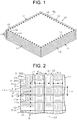
FIG. 1 is a view schematically showing a fiber-reinforced composite material of a present embodiment. -
FIG. 2 is a partial plan view showing a fiber structure of the present embodiment. -
FIG. 3 is a view of the fiber structure of the present embodiment as viewed in the direction indicated by arrow A ofFIG. 2 . -
FIG. 4 is a view of the fiber structure of the present embodiment as viewed in the direction indicated by arrow B ofFIG. 2 . -
FIG. 5 is an enlarged view showing a fabric-style fixing portion. -
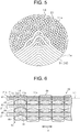
FIG. 6 is a schematic view showing a fiber structure formed by 3D-weave. -
FIG. 7 is a view showing another embodiment of fabric-style fixing portions. -
FIG. 8 is a view showing still another embodiment of fabric-style fixing portions. - A fiber structure and a fiber-reinforced composite material according to an embodiment of the present invention will now be described with reference to
FIG. 1 to FIG. 5 . - Referring to
FIG. 1 , a fiber-reinforcedcomposite material 10 is formed by impregnating a reinforcing base material being afiber structure 11 made of a multilayer fabric with matrix resin Ma. As the matrix resin Ma, for example, thermosetting epoxy resin is used. Thefiber structure 11 is formed by laminating a plurality offabrics 20. - Referring to
FIG. 2 , eachfabric 20 is formed by interlacing a plurality ofwarps 21 with a plurality ofwefts 31, and has a rectangular shape in a plan view. Thewarps 21 and thewefts 31 correspond to first yarns and second yarns, respectively. Eachfabric 20 is formed by plain weave to interlace thewarps 21 and thewefts 31. Thewefts 31 are arranged orthogonally to thewarps 21. Thewarps 21 and thewefts 31 are made ofdiscontinuous fibers 11a. Organic fibers and inorganic fibers that are the reinforcing fibers may be used as thediscontinuous fibers 11a. The organic fibers include aramid fibers, poly(p-phenylenebenzobisoxazole) fibers, ultra-high molecular weight polyethylene fibers, and the like. The inorganic fibers include carbon fibers, glass fibers, ceramic fibers, and the like. The form of yarn bundles made of thediscontinuous fibers 11a includes a spun yarn, a stretch-broken yarn, and the like. - The direction in which a yarn main axis L1 of the
warps 21 extends is defined as the first direction X of thefiber structure 11. The direction in which a yarn main axis L2 of thewefts 31 extends, and orthogonal to the first direction X is defined as the second direction Y of thefiber structure 11. The plurality of thewarps 21 are arranged side by side in the second direction Y of thefiber structure 11 and parallel to each other in thefiber structure 11. Furthermore, the plurality of thewefts 31 are arranged side by side in the first direction X of thefiber structure 11 and parallel to each other in thefiber structure 11. Referring toFIG. 3 , thefabrics 20 overlapped in the lamination direction are configured such that thewarps 21 of onefabric 20 overlap with thewefts 31 of theother fabric 20 in thefiber structure 11. The onefabric 20 is laminated on theother fabric 20. Thefabrics 20 overlapped in the lamination direction are bound in the lamination direction by binder yarns (not shown). - Referring to
FIG. 2 , thefiber structure 11 includes opposite first fabric edges 12 of the multilayer fabric where theends 21a of thewarps 21 are located in a yarn main axis direction of the warps 21 (the first direction X). In each of the first fabric edges 12, thewefts 31 are located more inside than theend 21a of thewarps 21 in the first direction X (closer to the center of the fiber structure 11). Of the plurality of thewefts 31 arranged side by side in the first direction X forming thesecond fabric edge 13, theoutermost weft 31 located closest to theends 21a of thewarps 21 and at the outermost side is anoutermost weft 32 as the outermost yarn. In this case, thewarps 21 correspond to one of the two types of yarns, and thewefts 31 correspond to the other of the two types of yarns. Theoutermost weft 32 is arranged beside theends 21a of thewarps 21. Therefore, in thefirst fabric edge 12, theoutermost weft 32 is located at a position closer to the center of thefiber structure 11 than theend 21a of thewarps 21. - The
fiber structure 11 includes opposite second fabric edges 13 of the multilayer fabric where theends 31a of thewefts 31 are located in the yarn main axis direction of the wefts 31 (the second direction Y). In each of the second fabric edges 13, thewarps 21 are located more inside than theend 31a of thewefts 31 in the second direction Y (closer to the center of the fiber structure 11). Of the plurality of thewarps 21 arranged side by side in the second direction Y forming thefirst fabric edge 12, theoutermost warp 21 located closest to theends 31a of thewefts 31 and at the outermost side is anoutermost warp 22 as the outermost yarn. In thesecond fabric edge 13, theoutermost warp 22 is located at a position closer to the center of thefiber structure 11 than theend 31a of thewefts 31. In this case, thewefts 31 correspond to the one of the two types of yarns, and thewarps 21 correspond to the other of the two types of yarns. Theoutermost warp 22 is arranged beside theends 31a of thewefts 31. - The
fiber structure 11 includes fabric-style fixing portions 14 in each of the first fabric edges 12 and each of the second fabric edges 13. The fabric-style fixing portions 14 disposed in thefirst fabric edge 12 are formed by needle punching on theoutermost weft 32. - Referring to
FIG. 3 or FIG. 4 , the fabric-style fixing portions 14 disposed in thefirst fabric edge 12 are formed to entangle thediscontinuous fibers 11a of theoutermost weft 32 and thewarps 21 overlapping theoutermost weft 32 in the lamination direction with each other in eachfabric 20. In other words, the fabric-style fixing portions 14 disposed in thefirst fabric edge 12 are formed to entangle thediscontinuous fibers 11a of theoutermost weft 32 of the onefabric 20 and thewarps 21 of theother fabric 20 with each other between thefabrics 20 overlapped in the lamination direction. When thefabrics 20 are punched through with a needle N at the opposite sides of eachwarp 21 in the width direction, the fabric-style fixing portions 14 are formed to entangle thediscontinuous fibers 11a of thewefts 31 overlapped in the lamination direction with each other, which is not illustrated. - Referring to
FIG. 2 , the fabric-style fixing portions 14 disposed in thesecond fabric edge 13 are formed by needle punching on theoutermost warp 22. The fabric-style fixing portions 14 disposed in thesecond fabric edge 13 are formed to entangle thediscontinuous fibers 11a of theoutermost warp 22 and thewefts 31 overlapping theoutermost warp 22 in the lamination direction with each other in eachfabric 20. The fabric-style fixing portions 14 disposed in thesecond fabric edge 13 are formed to entangle thediscontinuous fibers 11a of theoutermost warp 22 of the onefabric 20 and thewefts 31 of theother fabric 20 with each other between thefabrics 20 overlapped in the lamination direction. When thefabrics 20 are punched through with a needle N at the opposite sides of eachweft 31 in the width direction, the fabric-style fixing portions 14 are formed to entangle thediscontinuous fibers 11a of thewefts 31 overlapped in the lamination direction with each other, which is not illustrated. - Referring to
FIG. 5 , in the fabric-style fixing portions 14 of the configuration described above, thediscontinuous fibers 11a are twisted and entangled in a complicated manner between thewarps 21 and thewefts 31, between thewarps 21, and between thewefts 31, overlapped in the lamination direction. The warps 21 and thewefts 31 are made of thediscontinuous fibers 11a, so that thediscontinuous fibers 11a are entangled in many portions at the fabric-style fixing portions 14. - The
fiber structure 11 made of a multilayer fabric configured as described above is impregnated with matrix resin Ma, and then the matrix resin Ma is cured, thereby producing the fiber-reinforcedcomposite material 10. The impregnation and the cure of the matrix resin Ma is performed by, for example, RTM (resin transfer molding) method. When thefiber structure 11 is impregnated with the matrix resin Ma and the matrix resin Ma is cured, thewarps 21 and thewefts 31 of thefiber structure 11 are combined with the matrix resin Ma to produce the fiber-reinforcedcomposite material 10. - The following will describe an operation of the
fiber structure 11 and the fiber-reinforcedcomposite material 10. The fabric-style fixing portions 14 disposed in thefiber structure 11 prevent the fraying in thefirst fabric edge 12 and thesecond fabric edge 13. - The above-described embodiment has the following advantages.
- (1) The fabric-
style fixing portions 14 are formed by entangling the reinforcing fibers of yarns of thewarps 21 and thewefts 31 overlapped in the lamination direction of the multilayer fabric. Therefore, the fraying of thefirst fabric edge 12 and thesecond fabric edge 13 is prevented without using a separate member, resulting in saving of a manufacturing cost.
Furthermore, in the fiber-reinforcedcomposite material 10 formed by thefiber structure 11, the fraying is prevented without using a separating member. This means that, unlike the case in which separating members are added to prevent the fraying, a failure in impregnation of the matrix resin Ma (an adverse effect on the combining of the matrix resin Ma) does not occur, and the fiber-reinforcedcomposite material 10 does not lower a strength on account of separate members. - (2) The fabric-
style fixing portions 14 disposed in thefirst fabric edge 12 are formed by needle punching on theoutermost weft 32. This needle punching entangles thediscontinuous fibers 11a of theoutermost weft 32 having a possibility of being pulled out from thefirst fabric edge 12 and thewarps 21 with each other, thereby preventing theoutermost weft 32 from being pulled out. Furthermore, the fabric-style fixing portions 14 disposed in thesecond fabric edge 13 are formed by needle punching on theoutermost warp 22. This needle punching entangles thediscontinuous fibers 11a of theoutermost warp 22 having a possibility of being pulled out from thesecond fabric edge 13 and thewefts 31, thereby preventing theoutermost warp 22 from being pulled out. - (3) The fabric-
style fixing portions 14 disposed in each of the first fabric edges 12 and in each of the second fabric edges 13 are formed by needle punching on theoutermost weft 32 and on theoutermost warp 22, respectively. Therefore, thefiber structure 11 does not have the fabric-style fixing portions 14 more inside than theoutermost weft 32 in the first direction X (closer to the center of the fiber structure 11), and more inside than theoutermost warp 22 in the second direction Y (closer to the center of the fiber structure 11). As a result, in the produced fiber-reinforcedcomposite material 10, the twisting of thediscontinuous fibers 11a caused by forming the fabric-style fixing portions 14 is minimized, resulting in minimizing of the reduction in the strength of the fiber-reinforcedcomposite material 10. - (4) The
warps 21 and thewefts 31 are made of thediscontinuous fibers 11a. Thus, in the fabric-style fixing portions 14, thediscontinuous fibers 11a are entangled in many portions between thewarps 21 and thewefts 31, between thewarps 21, and between thewefts 31, overlapped in the lamination direction. Therefore, the fraying in the fabric-style fixing portions 14 is prevented, that is, the fraying in thefirst fabric edge 12 and thesecond fabric edge 13 is also prevented effectively. - The above embodiment may be modified as follows.
- The warps 21 and the
wefts 31 need not necessarily be made of thediscontinuous fibers 11a, and may be continuous yarns which are formed by bundling several hundreds to several tens of thousands of continuous fibers. - As shown in
FIG. 6 , afiber structure 40 may be a multilayer fabric formed by 3D-weave. Thefiber structure 40 includes warp layers 41, 43, 45 in each of which thewarps 21 corresponding to the first yarns are arranged parallel to each other, andweft layers wefts 31 corresponding to the second yarns are arranged to each other. Specifically, thefiber structure 40 includes thefirst warp layer 41, thefirst weft layer 42, thesecond warp layer 43, thesecond weft layer 44, thethird warp layer 45, and thethird weft layer 46 in this order from top to bottom. - In the
fiber structure 40, thefirst warp layer 41, thefirst weft layer 42, thesecond warp layer 43, thesecond weft layer 44, thethird warp layer 45, and thethird weft layer 46 are bound bybinder yarns 48 in the lamination direction. Thebinder yarns 48 are warps used for holding the shape of thefiber structure 40. - The
fiber structure 40 includes the fabric-style fixing portions 14 in opposite first fabric edges 51 in which theends 21a of thewarps 21 are located in the yarn main axis direction of thewarps 21. Furthermore, thefiber structure 40 includes the fabric-style fixing portions 14 in opposite second fabric edges in which theends 31a of thewefts 31 are located in the yarn main axis direction of thewefts 31, which is not illustrated. - As shown in
FIG. 7 , in eachfirst fabric edge 12, a plurality of the fabric-style fixing portions 14 may be disposed along the first direction X by needle punching on thewefts 31 which are located more inside than theoutermost weft 32 in the first direction X. Similar to thefirst fabric edge 12, in eachsecond fabric edge 13, a plurality of the fabric-style fixing portions 14 may be disposed along the second direction Y by needle punching on thewarps 21 which are located more inside than theoutermost warp 22 in the second direction Y. - As shown in
FIG. 8 , in eachfirst fabric edge 12, the fabric-style fixing portions 14 may be disposed only in theends 21a of thewarps 21 which are located more outside than theoutermost weft 32 in the first direction X. In other words, the fabric-style fixing portions 14 may be disposed in theends 21a of thewarps 21 that are located closer to the ends than theoutermost weft 32 in the yarn main axis direction of thewarps 21 corresponding to the one of the two types of yarns (in the first direction X). Similar to thefirst fabric edge 12, in eachsecond fabric edge 13, the fabric-style fixing portions 14 may be disposed only in theends 31a of thewefts 31 which are located more outside than theoutermost warp 22 in the second direction Y. In other words, the fabric-style fixing portions 14 may be disposed in theends 31a of thewefts 31 that are located closer to the ends than theoutermost warp 22 in the yarn main axis direction of thewefts 31 corresponding to the one of the two types of yarns (in the second direction Y). - With this configuration, in the
first fabric edge 12, thediscontinuous fibers 11a are entangled between thewarps 21 overlapped in the lamination direction in theends 21a closer to the ends in the yarn main axis direction of thewarps 21 than theoutermost weft 32, so that theoutermost weft 32 is prevented from being pulling out over theends 21a of thewarps 21. Similar to thefirst fabric edge 12, in thesecond fabric edge 13, thediscontinuous fibers 11a are entangled between thewefts 31 overlapped in the lamination direction in theends 31a closer to the ends in the yarn main axis direction of thewefts 31 than theoutermost warp 22, so that theoutermost warp 22 is prevented from being pulling out over theend 31a of thewefts 31. Thus, forming the fabric-style fixing portions 14 prevent the fraying in thefabric edge style fixing portions 14 are formed such that thediscontinuous fibers 11a are entangled between thewarps 21 overlapped in the lamination direction, and between thewefts 31 overlapped in the lamination direction. Therefore, no separate members are needed to prevent the fraying in thefabric edge - The fabric-
style fixing portions 14 may be added by needle punching on theoutermost weft 32 in eachfirst fabric edge 12 and on theoutermost warp 22 in eachsecond fabric edge 13. Owing to this addition, both the fabric-style fixing portions 14 which are located on theoutermost weft 32 and the fabric-style fixing portions 14 which are located on theends 21a of thewarps 21 cooperate to effectively prevent the fraying in thefirst fabric edge 12. Similar to thefirst fabric edge 12, both the fabric-style fixing portions 14 which are located on theoutermost warp 22 and the fabric-style fixing portions 14 which are located on eachend 31a of thewefts 31 cooperate to effectively prevent the fraying in thesecond fabric edge 13. - The fabric-
style fixing portions 14 may be disposed in only either the first fabric edges 12 and the second fabric edges 13 in thefiber structure 11, and in only either the first fabric edges 51 and the second fabric edges in thefiber structure 40. In this case, the opposite edges on the upstream and downstream sides in the weaving direction of thefiber structures fiber structures style fixing portions 14 may be disposed only in the cut edges and may not be disposed in the opposite sides in the weaving width direction. - Although needle punching is applied as a method to form the fabric-
style fixing portions 14, tufting may be applied. Besides needle punching and tufting, any method may be applied if the reinforcing fibers (thediscontinuous fibers 11a) are entangled with each other between adjacent layers. - Although the
fabrics 20 are formed by plain weave in the above embodiment, thefabrics 20 may be formed by satin weave or twill weave. - The number of laminated weft layers and warp layers may be changed as required in the
fiber structure 40. - When the
fiber structures composite material 10, the type of matrix resin and the method for manufacturing the fiber-reinforcedcomposite material 10 are not limited to any particular resin or method. - Next, the following will describe a technical idea comprehended from the above embodiment and the modifications.
- (1) In the fiber structure, the fabric-style fixing portions are formed by needle punching.
-
- Ma
- matrix resin
- 10
- fiber-reinforced composite material
- 11, 40
- fiber structure
- 11a
- discontinuous fiber
- 12, 51
- first fabric edge
- 13
- second fabric edge
- 14
- fabric-style fixing portion
- 20
- fabric
- 21
- warp corresponding to the first yarn
- 21a, 31a
- end
- 22
- outermost warp corresponding to the outermost yarn
- 31
- weft corresponding to the second yarn
- 32
- outermost weft corresponding to the outermost yarn
Claims (5)
- A fiber structure comprising:a multilayer fabric including:first yarns; andsecond yarns arranged orthogonally to the first yarns,the first yarns and the second yarns being bundles of reinforcing fibers, whereinthe fiber structure includes:a first fabric edge of the multilayer fabric where ends of the first yarns are located in a yarn main axis direction of the first yarns;a second fabric edge of the multilayer fabric where ends of the second yarns are located in a yarn main axis direction of the second yarns; andfabric-style fixing portions disposed in at least one of the first fabric edge and the second fabric edge,the fabric-style fixing portions are formed by entangling the reinforcing fibers of yarns of the first yarns and the second yarns overlapped in a lamination direction of the multilayer fabric,the fabric-style fixing portions are formed in at least one of an outermost yarn and ends of one of the two types of yarns, whereinof the one of the two types of yarns arranged side by side in a yarn main axis direction of the other of the two types of yarns forming the fabric edges, the outermost yarn is located closest to the ends of the other of the two types of yarns,the ends of the one of the two types of yarns are located closer to the ends than the outermost yarn in the yarn main axis direction of the one of the two types of yarns.
- The fiber structure according to claim 1, wherein the fabric-style fixing portions are disposed only in the outermost yarn.
- The fiber structure according to claim 1 or 2, wherein the first yarns and the second yarns are made of discontinuous fibers.
- The fiber structure according to any one of claims 1 to 3, wherein the fabric-style fixing portions are formed by needle punching.
- A fiber-reinforced composite material formed by impregnating a reinforcing base material being the fiber structure with matrix resin, wherein
the fiber structure is a fiber structure according to any one of claims 1 to 4.
Applications Claiming Priority (2)
| Application Number | Priority Date | Filing Date | Title |
|---|---|---|---|
| JP2017021130A JP6620771B2 (en) | 2017-02-08 | 2017-02-08 | Fiber structure and fiber reinforced composite |
| PCT/JP2018/001963 WO2018147072A1 (en) | 2017-02-08 | 2018-01-23 | Fiber structure and fiber reinforced composite material |
Publications (2)
| Publication Number | Publication Date |
|---|---|
| EP3581690A1 true EP3581690A1 (en) | 2019-12-18 |
| EP3581690A4 EP3581690A4 (en) | 2020-02-26 |
Family
ID=63107370
Family Applications (1)
| Application Number | Title | Priority Date | Filing Date |
|---|---|---|---|
| EP18751594.5A Withdrawn EP3581690A4 (en) | 2017-02-08 | 2018-01-23 | Fiber structure and fiber reinforced composite material |
Country Status (5)
| Country | Link |
|---|---|
| US (1) | US20200032433A1 (en) |
| EP (1) | EP3581690A4 (en) |
| JP (1) | JP6620771B2 (en) |
| CN (1) | CN110291239A (en) |
| WO (1) | WO2018147072A1 (en) |
Families Citing this family (1)
| Publication number | Priority date | Publication date | Assignee | Title |
|---|---|---|---|---|
| JP7715075B2 (en) * | 2022-04-22 | 2025-07-30 | 株式会社豊田自動織機 | Fiber structures and fiber-reinforced composites |
Family Cites Families (8)
| Publication number | Priority date | Publication date | Assignee | Title |
|---|---|---|---|---|
| FR2669940B1 (en) * | 1990-12-03 | 1994-10-21 | Europ Propulsion | WIRE FORMED FROM REFRACTORY FIBERS OR PRECURSORS THEREOF AND ITS APPLICATION TO THE MANUFACTURE OF PARTS OF COMPOSITE MATERIAL. |
| JP2002249957A (en) | 2001-02-20 | 2002-09-06 | Hiroharu Oishibashi | Apparatus for manufacturing widened yarn-woven fabric |
| JP2007182661A (en) * | 2005-12-09 | 2007-07-19 | Toray Ind Inc | Multi-axial molding material, preform, FRP and method for producing them |
| US20090209155A1 (en) * | 2008-02-15 | 2009-08-20 | Chapman Thermal Products, Inc. | Layered thermally-insulating fabric with thin heat reflective and heat distributing core |
| JP2011202304A (en) * | 2010-03-25 | 2011-10-13 | Toray Ind Inc | Fiber structure and method for producing the same, and preform |
| JP2013011027A (en) * | 2011-06-28 | 2013-01-17 | Toray Ind Inc | Fabric for reinforcement and weaving method thereof |
| US20140206248A1 (en) * | 2011-12-20 | 2014-07-24 | Matscitechno Licensing Company | Impact dissipating fabric |
| WO2015129684A1 (en) * | 2014-02-28 | 2015-09-03 | 東レ株式会社 | Woven fabric, and airbag |
-
2017
- 2017-02-08 JP JP2017021130A patent/JP6620771B2/en not_active Expired - Fee Related
-
2018
- 2018-01-23 WO PCT/JP2018/001963 patent/WO2018147072A1/en not_active Ceased
- 2018-01-23 US US16/484,230 patent/US20200032433A1/en not_active Abandoned
- 2018-01-23 EP EP18751594.5A patent/EP3581690A4/en not_active Withdrawn
- 2018-01-23 CN CN201880009765.8A patent/CN110291239A/en not_active Withdrawn
Also Published As
| Publication number | Publication date |
|---|---|
| JP6620771B2 (en) | 2019-12-18 |
| JP2018127732A (en) | 2018-08-16 |
| US20200032433A1 (en) | 2020-01-30 |
| EP3581690A4 (en) | 2020-02-26 |
| CN110291239A (en) | 2019-09-27 |
| WO2018147072A1 (en) | 2018-08-16 |
Similar Documents
| Publication | Publication Date | Title |
|---|---|---|
| JP2022182789A (en) | Fiber structure, and fiber-reinforced composite material | |
| JP2011074207A (en) | Preform of fiber reinforced composite material and method for producing the same | |
| EP3604649A1 (en) | Fibrous structure and fiber-reinforced composite material | |
| EP3712309A1 (en) | Fiber construct, fiber-reinforced composite material, and method for manufacturing these | |
| WO2015079854A1 (en) | Fiber-reinforced composite material | |
| JP6607026B2 (en) | Fiber reinforced composite | |
| US20200032433A1 (en) | Fiber structure and fiber reinforced composite material | |
| JP2017075428A (en) | Multilayer fabric | |
| JP5644755B2 (en) | Textile substrate and fiber reinforced composite material | |
| US10544525B2 (en) | Fibrous structure and fiber-reinforced composite material | |
| JP2021025164A (en) | Fiber structure and fiber-reinforce composite material | |
| US20250257502A1 (en) | Fiber structure and fiber-reinforced composite material | |
| JP7287162B2 (en) | Fiber structures and fiber reinforced composites | |
| JP6790967B2 (en) | Fiber structure and fiber reinforced composite | |
| WO2012014613A1 (en) | Fiber substrate and fiber-reinforced composite material | |
| WO2013035518A1 (en) | Woven fabric base material and fiber-reinforced composite material | |
| EP4549640A1 (en) | Fiber structure for fiber-reinforced composite material | |
| JP7609009B2 (en) | Fiber structures and fiber-reinforced composites | |
| WO2021006081A1 (en) | Fiber structure and method for manufacturing fiber structure | |
| JP7845244B2 (en) | Fiber structures and fiber-reinforced composites | |
| JP4069202B2 (en) | Method for producing three-dimensional fiber reinforced composite lugs | |
| JP2022119368A (en) | Fiber structure and fiber-reinforced composite material | |
| JP2026000064A (en) | Fiber structures and fiber-reinforced composites | |
| JP2015098156A (en) | Three-dimensional fiber-reinforced composite material | |
| JP2022122656A (en) | Fiber structure, fiber-reinforced composite material, and fiber structure manufacturing method |
Legal Events
| Date | Code | Title | Description |
|---|---|---|---|
| PUAI | Public reference made under article 153(3) epc to a published international application that has entered the european phase |
Free format text: ORIGINAL CODE: 0009012 |
|
| 17P | Request for examination filed |
Effective date: 20190807 |
|
| AK | Designated contracting states |
Kind code of ref document: A1 Designated state(s): AL AT BE BG CH CY CZ DE DK EE ES FI FR GB GR HR HU IE IS IT LI LT LU LV MC MK MT NL NO PL PT RO RS SE SI SK SM TR |
|
| AX | Request for extension of the european patent |
Extension state: BA ME |
|
| A4 | Supplementary search report drawn up and despatched |
Effective date: 20200128 |
|
| RIC1 | Information provided on ipc code assigned before grant |
Ipc: D03D 11/00 20060101ALI20200122BHEP Ipc: D03D 5/00 20060101ALI20200122BHEP Ipc: D03D 1/00 20060101AFI20200122BHEP Ipc: B29B 11/16 20060101ALI20200122BHEP |
|
| DAV | Request for validation of the european patent (deleted) | ||
| DAX | Request for extension of the european patent (deleted) | ||
| 17Q | First examination report despatched |
Effective date: 20200626 |
|
| STAA | Information on the status of an ep patent application or granted ep patent |
Free format text: STATUS: THE APPLICATION HAS BEEN WITHDRAWN |
|
| 18W | Application withdrawn |
Effective date: 20200923 |