EP3581483A1 - Load-transferring connection between structurally loaded components - Google Patents
Load-transferring connection between structurally loaded components Download PDFInfo
- Publication number
- EP3581483A1 EP3581483A1 EP19178536.9A EP19178536A EP3581483A1 EP 3581483 A1 EP3581483 A1 EP 3581483A1 EP 19178536 A EP19178536 A EP 19178536A EP 3581483 A1 EP3581483 A1 EP 3581483A1
- Authority
- EP
- European Patent Office
- Prior art keywords
- strap
- stiffening rib
- component
- section
- fastener
- Prior art date
- Legal status (The legal status is an assumption and is not a legal conclusion. Google has not performed a legal analysis and makes no representation as to the accuracy of the status listed.)
- Granted
Links
Images






Classifications
-
- F—MECHANICAL ENGINEERING; LIGHTING; HEATING; WEAPONS; BLASTING
- F16—ENGINEERING ELEMENTS AND UNITS; GENERAL MEASURES FOR PRODUCING AND MAINTAINING EFFECTIVE FUNCTIONING OF MACHINES OR INSTALLATIONS; THERMAL INSULATION IN GENERAL
- F16B—DEVICES FOR FASTENING OR SECURING CONSTRUCTIONAL ELEMENTS OR MACHINE PARTS TOGETHER, e.g. NAILS, BOLTS, CIRCLIPS, CLAMPS, CLIPS OR WEDGES; JOINTS OR JOINTING
- F16B2/00—Friction-grip releasable fastenings
- F16B2/02—Clamps, i.e. with gripping action effected by positive means other than the inherent resistance to deformation of the material of the fastening
- F16B2/06—Clamps, i.e. with gripping action effected by positive means other than the inherent resistance to deformation of the material of the fastening external, i.e. with contracting action
- F16B2/08—Clamps, i.e. with gripping action effected by positive means other than the inherent resistance to deformation of the material of the fastening external, i.e. with contracting action using bands
-
- F—MECHANICAL ENGINEERING; LIGHTING; HEATING; WEAPONS; BLASTING
- F16—ENGINEERING ELEMENTS AND UNITS; GENERAL MEASURES FOR PRODUCING AND MAINTAINING EFFECTIVE FUNCTIONING OF MACHINES OR INSTALLATIONS; THERMAL INSULATION IN GENERAL
- F16B—DEVICES FOR FASTENING OR SECURING CONSTRUCTIONAL ELEMENTS OR MACHINE PARTS TOGETHER, e.g. NAILS, BOLTS, CIRCLIPS, CLAMPS, CLIPS OR WEDGES; JOINTS OR JOINTING
- F16B5/00—Joining sheets or plates, e.g. panels, to one another or to strips or bars parallel to them
- F16B5/06—Joining sheets or plates, e.g. panels, to one another or to strips or bars parallel to them by means of clamps or clips
- F16B5/0607—Joining sheets or plates, e.g. panels, to one another or to strips or bars parallel to them by means of clamps or clips joining sheets or plates to each other
- F16B5/0621—Joining sheets or plates, e.g. panels, to one another or to strips or bars parallel to them by means of clamps or clips joining sheets or plates to each other in parallel relationship
-
- B—PERFORMING OPERATIONS; TRANSPORTING
- B64—AIRCRAFT; AVIATION; COSMONAUTICS
- B64C—AEROPLANES; HELICOPTERS
- B64C1/00—Fuselages; Constructional features common to fuselages, wings, stabilising surfaces or the like
- B64C1/06—Frames; Stringers; Longerons ; Fuselage sections
- B64C1/066—Interior liners
-
- B—PERFORMING OPERATIONS; TRANSPORTING
- B64—AIRCRAFT; AVIATION; COSMONAUTICS
- B64C—AEROPLANES; HELICOPTERS
- B64C1/00—Fuselages; Constructional features common to fuselages, wings, stabilising surfaces or the like
- B64C1/06—Frames; Stringers; Longerons ; Fuselage sections
- B64C1/12—Construction or attachment of skin panels
-
- B—PERFORMING OPERATIONS; TRANSPORTING
- B64—AIRCRAFT; AVIATION; COSMONAUTICS
- B64C—AEROPLANES; HELICOPTERS
- B64C3/00—Wings
- B64C3/26—Construction, shape, or attachment of separate skins, e.g. panels
-
- B—PERFORMING OPERATIONS; TRANSPORTING
- B64—AIRCRAFT; AVIATION; COSMONAUTICS
- B64F—GROUND OR AIRCRAFT-CARRIER-DECK INSTALLATIONS SPECIALLY ADAPTED FOR USE IN CONNECTION WITH AIRCRAFT; DESIGNING, MANUFACTURING, ASSEMBLING, CLEANING, MAINTAINING OR REPAIRING AIRCRAFT, NOT OTHERWISE PROVIDED FOR; HANDLING, TRANSPORTING, TESTING OR INSPECTING AIRCRAFT COMPONENTS, NOT OTHERWISE PROVIDED FOR
- B64F5/00—Designing, manufacturing, assembling, cleaning, maintaining or repairing aircraft, not otherwise provided for; Handling, transporting, testing or inspecting aircraft components, not otherwise provided for
- B64F5/10—Manufacturing or assembling aircraft, e.g. jigs therefor
-
- B—PERFORMING OPERATIONS; TRANSPORTING
- B64—AIRCRAFT; AVIATION; COSMONAUTICS
- B64U—UNMANNED AERIAL VEHICLES [UAV]; EQUIPMENT THEREFOR
- B64U10/00—Type of UAV
- B64U10/25—Fixed-wing aircraft
-
- B—PERFORMING OPERATIONS; TRANSPORTING
- B64—AIRCRAFT; AVIATION; COSMONAUTICS
- B64U—UNMANNED AERIAL VEHICLES [UAV]; EQUIPMENT THEREFOR
- B64U20/00—Constructional aspects of UAVs
- B64U20/60—UAVs characterised by the material
- B64U20/65—Composite materials
-
- B—PERFORMING OPERATIONS; TRANSPORTING
- B64—AIRCRAFT; AVIATION; COSMONAUTICS
- B64C—AEROPLANES; HELICOPTERS
- B64C1/00—Fuselages; Constructional features common to fuselages, wings, stabilising surfaces or the like
- B64C2001/0054—Fuselage structures substantially made from particular materials
- B64C2001/0072—Fuselage structures substantially made from particular materials from composite materials
-
- F—MECHANICAL ENGINEERING; LIGHTING; HEATING; WEAPONS; BLASTING
- F16—ENGINEERING ELEMENTS AND UNITS; GENERAL MEASURES FOR PRODUCING AND MAINTAINING EFFECTIVE FUNCTIONING OF MACHINES OR INSTALLATIONS; THERMAL INSULATION IN GENERAL
- F16B—DEVICES FOR FASTENING OR SECURING CONSTRUCTIONAL ELEMENTS OR MACHINE PARTS TOGETHER, e.g. NAILS, BOLTS, CIRCLIPS, CLAMPS, CLIPS OR WEDGES; JOINTS OR JOINTING
- F16B5/00—Joining sheets or plates, e.g. panels, to one another or to strips or bars parallel to them
- F16B5/06—Joining sheets or plates, e.g. panels, to one another or to strips or bars parallel to them by means of clamps or clips
- F16B5/0607—Joining sheets or plates, e.g. panels, to one another or to strips or bars parallel to them by means of clamps or clips joining sheets or plates to each other
- F16B2005/0678—Joining sheets or plates, e.g. panels, to one another or to strips or bars parallel to them by means of clamps or clips joining sheets or plates to each other in abutting relationship
Definitions
- Advances in composite materials and composite structures are enabling new means of designing, manufacturing and producing lightweight components and shell-structures.
- Examples of such innovative approaches in new composite materials include the use of composite sandwich structures. These sandwich structures contain a lightweight foam material, sandwiched on either side with a composite (e.g., carbon fibre, Kevlar, or Zylon) skin.
- a composite e.g., carbon fibre, Kevlar, or Zylon
- Complex shapes can be formed using this technique, but the joining of such complex shapes together, especially if they form a critical part of the load bearing structure can be challenging.
- connection of highly loaded structural composite shells requires the use of rows of fasteners (e.g., rivets, nuts & bolts, nails, screws etc.) or the bonding of the structures with high strength glues.
- fasteners e.g., rivets, nuts & bolts, nails, screws etc.
- conventional fastening techniques e.g., quick-release fasteners, bolts, etc.
- the current application aims to provide a system that obviates, or at least lessens, said problems of prior art composite structures.
- the instant invention disclosed herein is directed to a system.
- the system includes a fastener strap, a first component, and a second component.
- the fastener strap includes a strap section, at least one first stiffening rib section, and at least one second stiffening rib section.
- the at least one first stiffening rib section and the at least one second stiffening rib section extend outwardly from a side of the strap section.
- the at least one first stiffening rib section and the at least one second stiffening rib section extend longitudinally along portions of the side of the strap section.
- the at least one first stiffening rib section is parallel to the at least one second stiffening rib section.
- the first component includes a first strap section channel and at least one first stiffening rib section channel positioned along the first strap section channel.
- the first strap section channel and the at least one first stiffening rib section channel are positioned along an edge of the first component.
- the first strap section channel is configured to receive a first portion of the strap section of the fastener strap.
- the at least one first stiffening rib section channel is configured to receive the at least one first stiffening rib section of the fastener strap.
- the second component includes a second strap section channel and at least one second stiffening rib section channel positioned along the second strap section channel.
- the second strap section channel and the at least one second stiffening rib section channel are positioned along an edge of the second component.
- the second strap section channel is configured to receive a second portion of the strap section of the fastener strap.
- the at least one second stiffening rib section channel may be configured to receive the at least one second stiffening rib section of the fastener strap.
- a letter following a reference numeral is intended to reference an embodiment of the feature or element that may be similar, but not necessarily identical, to a previously described element or feature bearing the same reference numeral (e.g., 1, 1 a, 1b).
- reference numeral e.g. 1, 1 a, 1b
- Such shorthand notations are used for purposes of convenience only, and should not be construed to limit the instant invention in any way unless expressly stated to the contrary.
- any reference to "one embodiment,” or “some embodiments” means that a particular element, feature, structure, or characteristic described in connection with the embodiment is included in at least one embodiment of the invention disclosed herein.
- the appearances of the phrase “in some embodiments” in various places in the specification are not necessarily all referring to the same embodiment, and embodiments of the invention disclosed may include one or more of the features expressly described or inherently present herein, or any combination of sub-combination of two or more such features, along with any other features which may not necessarily be expressly described or inherently present in the instant disclosure.
- embodiments of the instant invention disclosed herein are directed a method of creating and system of a load-transferring connection between structurally loaded components (e.g., composite shells or panels).
- structurally loaded components e.g., composite shells or panels.
- advanced materials and structures e.g., a laminate or a composite shell comprising a composite sandwich structure including a lightweight foam material core sandwiched on either side with a composite skin (e.g., carbon, Kevlar, or Zylon)
- a composite skin e.g., carbon, Kevlar, or Zylon
- the challenge lies in the assembly, disassembly and fixing of these extremely lightweight body-shell structures with equivalent strong and lightweight fastening solutions.
- Embodiments may include a connection (e.g., a fastener strap) that when installed can transfer structural loads from one loaded component (e.g., a composite shell or panel) to another loaded component, across edge interfaces of the loaded components.
- a connection e.g., a fastener strap
- Such connection may not affect aerodynamics or a profile such that the connection would have a smooth and flush interface between the two or more loaded components (e.g., composite structural shells or laminates).
- Such connection may be easy to assemble and disassemble as compared to a typical line of rivets or fasteners.
- Such connection may deliver quick rig and de-rig capability.
- Embodiments may include a lightweight, part rigid, part flexible thin composite fastener strap that is able to sustain sideways loads when installed.
- the fastener strap may include two or more stiffening ribs, set apart from each other by a certain distance. Each stiffening rib locks into an equivalent single channel formed within each of two components (e.g., composite shell structures or panels) to be joined.
- An additional load-bearing structure e.g., a support frame
- each extremity of the strap are location points which can be counter-sunk to enable a single attachment means (e.g., fastener, a quick-release fastener, a screw, a pin, a bolt, a nut, a latch, and/or holes) to lie flush with the strap and outer surfaces of the components (e.g., composite shell structures or panels) to be joined and tie the fastener strap to the lower support-bearing structure (e.g., support frame).
- a single attachment means e.g., fastener, a quick-release fastener, a screw, a pin, a bolt, a nut, a latch, and/or holes
- a single attachment means e.g., fastener, a quick-release fastener, a screw, a pin, a bolt, a nut, a latch, and/or holes
- a single attachment means e.g., fastener, a quick-release fastener, a screw, a
- Embodiments may allow for quick assembly and disassembly of subassemblies (e.g., vehicular or aircraft subassemblies). Additionally, embodiments may allow for continuity to an outer surface (e.g., a flushness across outers surfaces of two components and the fastener strap), that can be a key parameter for aerodynamic efficiency of aircraft exteriors and for cosmetic appearance and tribology wear & tear (e.g., from trolleys and passengers) in aircraft interiors.
- an outer surface e.g., a flushness across outers surfaces of two components and the fastener strap
- Embodiments may include a lightweight composite structure fastener strap.
- the fastener strap may include a double ribbed strap, by which the strap locks into channels of two components (e.g., composite shell structures or panels) by means of the ribs. These ribs may lock directly into channels that have been molded into or formed in the components (e.g., lightweight composite skins of composite shell structures or panels) that may butt up against an underlying load bearing structure (e.g., support frame).
- the composite, lightweight fastener strap may be flexible, such that fastener strap can be adapted through flexure to fit around lightweight composite skins and may immediately hold the two adjoining composite skins in place before the final attachment means (e.g., end fasteners) have been securely fixed. The entire fastener strap when fully fastened may lie flush with the other components being joined.
- Embodiments may include joining thin, lightweight composite shell-structures together in such a way that potentially high tensile and compressive loads can be evenly transmitted across the shell-structure joint without risk of joint or composite shell-structure failure. Furthermore, embodiments may also incorporate a lightweight, rapid assembly and disassembly method to quickly tie the composite shell-structures together as well as quickly release them, as and when required.
- the attachment means for fixing the fastener strap to the underlying load-bearing structure may be provided by a quick-release fastener, a screw, a pin, a bolt, a nut, a latch, a lock mechanism, a rivet, a mechanical pin device, and/or holes.
- Embodiments may include the use of extremely strong and lightweight composite sandwich structures comprising a thin (e.g., 3mm) lightweight foam core sandwiched between two very thin (e.g., 0.3mm to 0.6mm) external skins (e.g, carbon-fibre, Kevlar, Zylon or equivalent composite skins) to form a structural body component that can be joined to another component via a fastener strap.
- a thin lightweight foam core sandwiched between two very thin (e.g., 0.3mm to 0.6mm) external skins (e.g, carbon-fibre, Kevlar, Zylon or equivalent composite skins) to form a structural body component that can be joined to another component via a fastener strap.
- external skins e.g, carbon-fibre, Kevlar, Zylon or equivalent composite skins
- Embodiments may include a means of rigidly joining together by butting up two components (e.g., composite shell structures or panels) with a minimal, quick release fastening solution, such that compressive and tensile loads can be evenly transmitted through the joint without any stress raisers being present.
- two components e.g., composite shell structures or panels
- a minimal, quick release fastening solution such that compressive and tensile loads can be evenly transmitted through the joint without any stress raisers being present.
- Embodiments may include the ability to quickly and flexibly access components such as electronic sub-systems (e.g., batteries, wiring, computing devices, sensors, antennas, and/or connectors) underneath outer skin shell-structures (e.g., a wing section or fuselage section) by means of a quick assembly and quick release fastening mechanism enabling at least one of potentially multiple molded composite sandwich structures to be removed quickly and easily.
- electronic sub-systems e.g., batteries, wiring, computing devices, sensors, antennas, and/or connectors
- outer skin shell-structures e.g., a wing section or fuselage section
- the fastener strap may be installed in less than one minute to connect two components, and the fastener strap may be removed in less than one minute to disassemble two components.
- Embodiments may include providing attachment means coupled to a fastener strap, whereby the attachment means does not get easily dropped and get lost when working on the composite product in challenging environments.
- the attachment means may be affixed to the fastener strap.
- Embodiments may include the fastener strap being able to provide a precise, robust, quick-release mechanism, for connecting very thin, lightweight composite sandwich structures.
- Embodiments may include the ability to ensure that a joint is successfully sealed such that water (or other fluid) ingress is suppressed or at least minimized.
- the fastener strap may include a flexible section within the overall length of the fastener strap to enable the composite fastener strap to open up around a supporting structure (e.g., a wing-rib) and provide a natural clamping mechanism.
- a supporting structure e.g., a wing-rib
- the drone 100 may be composed of a plurality of composite shell components.
- the assembly of a drone fuselage body and associated wing shells may be manufactured using a composite shell-structure technique.
- the drone 100 may include a fuselage composite shell 104, two wing composite shells 106, and two rotor assembly composite shells 108 having rotors 110 attached thereto.
- the drone 100 may include fastener straps 102 that connect various of the composite shell components to one another.
- the fuselage composite shell 104 may be connected to the two wing composite shells 106 via two fastener straps 102.
- each of the two wing composite shells 106 may be connected to a rotor assembly composite shell 108 via a fastener strap 102.
- the fastener straps 102 allow the drone 100 to be quickly assembled and disassembled. When installed, the fastener straps 102 may evenly transmit compressive and tensile loads through joints with abutting composite shell components without any stress raisers being present.
- the fastener strap 102 may include a strap section 202, at least one (e.g., two, as shown) first stiffening rib section 206, at least one (e.g., two, as shown) second stiffening rib section 206, holes 204, a bolt 210, and a nut 212.
- the fastener strap 102 may be made of carbon fibre, Kevlar, Zylon, or a combination thereof.
- the at least one first stiffening rib section 206 and the at least one second stiffening rib section 206 may extend outwardly from a side (e.g., an inwardly facing side) of the strap section 202.
- the at least one first stiffening rib section 206 and the at least one second stiffening rib section 206 may extend longitudinally along portions of the side of the strap section 202.
- the at least one first stiffening rib section 206 may be parallel to the at least one second stiffening rib section 206.
- first stiffening rib sections 206 and two second stiffening rib sections 206 there is a first gap between the two first stiffening rib sections 206 and a second gap between the two second stiffening rib sections 206.
- the first gap and the second gap may be adjacently located along the fastener strap 102 at a more flexible section 208, wherein the fastener strap 102 may be more flexible at locations along the first and second gaps than at locations located along the two first stiffening rib sections 206 and the two second stiffening rib sections 206.
- first and second gaps may allow the fastener strap 102 to bend around corresponding curved sections (e.g., leading edges of wing sections) of first and second components (e.g., composite shell structures or panels) being joined.
- the stiffening rib sections 206 do not extend an entire length of the fastener strap 102; for example, a flexible section 208 of the fastener strap 102 may be rib-free.
- the flexible section 208 may enable the fastener strap 102 to be slipped over a joint easily and quickly.
- the flexible section 208 may act as a spring mechanism allowing the stiffening rib sections 206 to lock with channels formed in the two to-be-joined components (e.g., composite shell-structure components), thus already locking the two components together prior to, for example, final quick-release fasteners, screws, pins, or bolt fasteners being tightened up.
- two to-be-joined components e.g., composite shell-structure components
- the stiffening rib sections 206 may extend continuously and substantially (e.g., except for near the holes 204) the entire length of the fastener strap 102, for example, so that two panels (e.g., 1202, 1204) can be joined with two, oppositely installed fastening straps 102.
- the fastener strap 102 may include attachment means for securing first and second ends of the fastener strap 102 against a first component and the second component, as well as an underlying support frame (e.g., 304) (if any).
- the attachment means may include a quick-release fastener, a screw, a pin, a bolt 210, a nut 212, a latch, a lock mechanism, a rivet, a mechanical pin device, and/or holes 204.
- the holes 204 may be countersunk to accommodate quick-release fasteners, screws, pins, or bolts and so as to allow a quick-release fastener, a screw, a pin, a bolt 210, a nut 212, a latch, a lock mechanism, a rivet, and/or a mechanical pin device to be flush along an exterior surface of the fastener strap 102.
- FIG. 3 a cross-sectional view of an exemplary embodiment of a fastener strap 102 connecting two components 302 supported by a support frame 304 according to the invention disclosed herein is depicted.
- the two components 302 may be any suitable components to be joined by the fastener strap 102.
- the two components 302 may be implemented as composite shell components or panels.
- the two components 302 may be vehicular components (e.g., aircraft components, train components, watercraft components, and/or automobile components).
- the two components 302 may be implemented as or include at least one fuselage composite shell 104, at least one wing composite shell 106, and/or at least one rotor assembly composite shell 108.
- the two components 302 may be implemented as aircraft interior panels, such as used for seating assemblies or wall panels in an aircraft.
- the two components 302 may abut each other or an intervening support frame 304.
- the fastener strap 102 may fit over edges of the two components 302 and/or the support frame 304.
- the support frame 304 may support the edges of the two components 302 and a middle portion of the strap section 202 of the fastener strap 102.
- a first of the two components 302 may have a first strap section channel 308 and at least one first stiffening rib section channel 306 positioned along the first strap section channel 308.
- the first strap section channel 308 and the at least one first stiffening rib section channel 306 may be positioned along at least one edge of the first component 302.
- the first strap section channel 308 may be configured to receive a first portion of the strap section 202 of the fastener strap 102.
- the at least one first stiffening rib section channel 306 may be configured to receive the at least one first stiffening rib section 206 of the fastener strap 102.
- the first component 302 includes two first stiffening rib section channels 306 positioned along the first strap section channel 308 with a first corresponding gap between the two first stiffening rib section channels 306 such that the two first stiffening rib section channels 306 may be configured to receive the two first stiffening rib sections 206 of the fastener strap 102.
- a second of the two components 302 may have a second strap section channel 308 and at least one second stiffening rib section channel 306 positioned along the second strap section channel 308.
- the second strap section channel 308 and the at least one second stiffening rib section channel 306 may be positioned along at least one edge of the second component 302.
- the second strap section channel 308 may be configured to receive a second portion of the strap section 202 of the fastener strap 102.
- the at least one second stiffening rib section channel 306 may be configured to receive the at least one second stiffening rib section 206 of the fastener strap 102.
- the second component 302 includes two second stiffening rib section channels 306 positioned along the second strap section channel 308 with a second corresponding gap between the two second stiffening rib section channels 306 such that the two second stiffening rib section channels 306 may be configured to receive the two second stiffening rib sections 206 of the fastener strap 102.
- FIG. 4 a perspective view of an exemplary embodiment of a support frame 304 according to the invention disclosed herein is depicted.
- the support frame 304 depicted is a drone wing rib; however, any suitable support frame may be used for any suitable application.
- the support frame 304 may include at least one hole 404 configured to accommodate a screw, a pin, a bolt 210, a rivet, and/or a mechanical pin device of the attachment means. In some embodiments, the at least one hole 404 is threaded.
- the support frame 304 may include ridges 402 configured to accommodate composite shells components (e.g., 104, 106, 108).
- the support frame 304 may include a central opening where cables and wires can pass through a wing of a drone 100.
- the component 302 depicted is a wing composite shell (e.g., 106).
- the component 302 may include two stiffening rib section channels 306 positioned along the strap section channel 308.
- the component may include a stiffening rib section channel 306 on a top side of the wing composite shell (e.g., 106) and a stiffening rib section channel 306 on the bottom side of the wing composite shell (e.g., 106).
- the shape and configuration of the channels 306, 308 may be designed so that the channels 306, 308 provide a self-locking or self-fixing fit when the fastener strap 102 is inserted into the channels 306, 308.
- FIG. 7 a perspective cut-away view of an exemplary embodiment of a component 302, a support frame 304, and a fastener strap 102 according to the invention disclosed herein is depicted.
- the component 302 depicted is a wing composite shell (e.g., 106).
- FIG. 8 a perspective cut-away view of an exemplary embodiment of a first component 302, a second component (e.g., fuselage composite shell 104), a support frame 304, and a fastener strap 102 according to the invention disclosed herein is depicted.
- the component 302 depicted is a wing composite shell (e.g., 106).
- the fastener strap 102 may be configured to connect the first component (e.g., a wing composite shell (e.g., 106)) to the second component (e.g., fuselage composite shell 104).
- the fastener strap 102 may be flush with the exterior surfaces of the first component (e.g., a wing composite shell (e.g., 106)) and the second component (e.g., fuselage composite shell 104).
- FIG. 9 perspective views of an exemplary embodiment of a first panel 902, a second panel 904, and at least one fastener strap 102 implemented in an interior of an aircraft according to the invention disclosed herein are depicted.
- the panels 902, 904 may be implemented as aircraft interior panels.
- the panel 902 may be a wall panel.
- the panel 904 may be a panel of an aircraft seating assembly.
- the panels 902, 904 may be composite structurally loaded panels in an aircraft interior. Embodiments may be applied to aircraft interiors, where surface continuity, strong structural connection and easy rig and de-rig are important.
- the panels 902, 904 may be joined with two fastener straps 102.
- the two fastener straps 102 may be configured to connect the panel 902 to the panel 904.
- a first fastener strap 102 (shown) may be installed in channels 306, 308 of first sides of the panels 902, 904.
- a second fastener strap 102 (not shown) may be installed in channels 306, 308 of second sides of the panels 902, 904.
- the second fastener strap 102 (not shown) may be installed on opposite sides of the panels 902, 904 as the first fastener strap 102 (shown).
- a load-bearing connection may be formed between the panels 902, 904.
- FIGS. 10-11 a front view and an exploded top perspective view of an exemplary embodiment of a first panel 1002, a second panel 1004, and at least one fastener strap 102 according to the invention disclosed herein are depicted.
- a load-bearing connection may be formed between the panels 1002, 1004.
- FIG. 12 a top perspective view of an exemplary embodiment of a first panel 1202, a second panel 1204, and two fastener straps 102 according to the invention disclosed herein is depicted.
- the two fastener straps 102 may be configured to connect the panel 1202 to the panel 1204.
- a first fastener strap 102 may be installed in channels 306, 308 of first sides of the panels 1202, 1204.
- a second fastener strap 102 may be installed in channels 306, 308 of second sides of the panels 1202, 1204.
- the second fastener strap 102 may be installed on opposite sides of the panels 1202, 1204 as the first fastener strap 102.
- a load-bearing connection may be formed between the panels 1202, 1204.
- embodiments of the invention disclosed herein may be directed to a method of creating and system of a load-transferring connection between structurally loaded components (e.g., composite shells or panels).
- structurally loaded components e.g., composite shells or panels.
- At least one means one or a plurality of; for example, “at least one” may comprise one, two, three, ..., one hundred, or more.
- one or more means one or a plurality of; for example, “one or more” may comprise one, two, three, ..., one hundred, or more.
- zero or more means zero, one, or a plurality of; for example, “zero or more” may comprise zero, one, two, three, ..., one hundred, or more.
- the methods, operations, and/or functionality disclosed may be implemented as sets of instructions or software readable by a device. Further, it is understood that the specific order or hierarchy of steps in the methods, operations, and/or functionality disclosed are examples of exemplary approaches. Based upon design preferences, it is understood that the specific order or hierarchy of steps in the methods, operations, and/or functionality can be rearranged while remaining within the scope of the invention disclosed herein.
- embodiments of the methods according to the invention disclosed herein may include one or more of the steps described herein. Further, such steps may be carried out in any desired order and two or more of the steps may be carried out simultaneously with one another. Two or more of the steps disclosed herein may be combined in a single step, and in some embodiments, one or more of the steps may be carried out as two or more sub-steps. Further, other steps or sub-steps may be carried in addition to, or as substitutes to one or more of the steps disclosed herein.
Landscapes
- Engineering & Computer Science (AREA)
- Mechanical Engineering (AREA)
- Aviation & Aerospace Engineering (AREA)
- Remote Sensing (AREA)
- General Engineering & Computer Science (AREA)
- Manufacturing & Machinery (AREA)
- Chemical & Material Sciences (AREA)
- Composite Materials (AREA)
- Materials Engineering (AREA)
- Transportation (AREA)
- Connection Of Plates (AREA)
Abstract
Description
- Advances in composite materials and composite structures are enabling new means of designing, manufacturing and producing lightweight components and shell-structures. Examples of such innovative approaches in new composite materials include the use of composite sandwich structures. These sandwich structures contain a lightweight foam material, sandwiched on either side with a composite (e.g., carbon fibre, Kevlar, or Zylon) skin. Complex shapes can be formed using this technique, but the joining of such complex shapes together, especially if they form a critical part of the load bearing structure can be challenging.
- Typically, connection of highly loaded structural composite shells requires the use of rows of fasteners (e.g., rivets, nuts & bolts, nails, screws etc.) or the bonding of the structures with high strength glues. The use of conventional fastening techniques (e.g., quick-release fasteners, bolts, etc.) not only creates point stress-loadings along the joint, but due to the number of fasteners required, adds significant weight and adds fastening and unfastening complexity to the assembly and disassembly process which can add significant time to maintenance and repair operations.
- The current application aims to provide a system that obviates, or at least lessens, said problems of prior art composite structures. In one aspect, the instant invention disclosed herein is directed to a system. The system includes a fastener strap, a first component, and a second component. The fastener strap includes a strap section, at least one first stiffening rib section, and at least one second stiffening rib section. The at least one first stiffening rib section and the at least one second stiffening rib section extend outwardly from a side of the strap section. The at least one first stiffening rib section and the at least one second stiffening rib section extend longitudinally along portions of the side of the strap section. The at least one first stiffening rib section is parallel to the at least one second stiffening rib section. The first component includes a first strap section channel and at least one first stiffening rib section channel positioned along the first strap section channel. The first strap section channel and the at least one first stiffening rib section channel are positioned along an edge of the first component. The first strap section channel is configured to receive a first portion of the strap section of the fastener strap. The at least one first stiffening rib section channel is configured to receive the at least one first stiffening rib section of the fastener strap. The second component includes a second strap section channel and at least one second stiffening rib section channel positioned along the second strap section channel. The second strap section channel and the at least one second stiffening rib section channel are positioned along an edge of the second component. The second strap section channel is configured to receive a second portion of the strap section of the fastener strap. The at least one second stiffening rib section channel may be configured to receive the at least one second stiffening rib section of the fastener strap. When the fastener strap is installed in the first strap section channel, the at least one first stiffening rib section channel, the second strap section channel, and the at least one second stiffening rib section channel, a load-bearing connection is formed between the first component and the second component.
- Implementations of the instant invention disclosed herein may be better understood when consideration is given to the following detailed description thereof. Such description makes reference to the included drawings, which are not necessarily to scale, and in which some features may be exaggerated and some features may be omitted or may be represented schematically in the interest of clarity. Like reference numerals in the drawings may represent and refer to the same or similar element, feature, or function. In the drawings:
-
FIG. 1 is a view of an exemplary embodiment of a drone according to the instant invention. -
FIG. 2 is a view of an exemplary embodiment of a fastener strap according to the instant invention. -
FIG. 3 is a cross-sectional view of an exemplary embodiment of a fastener strap connecting two components supported by a support frame according to the instant invention. -
FIG. 4 is a perspective view of an exemplary embodiment of a support frame according to the instant invention. -
FIG. 5 is a perspective view of an exemplary embodiment of a component according to the instant invention. -
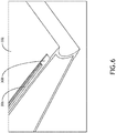
FIG. 6 is a further perspective view of the component ofFIG. 5 according to the instant invention. -
FIG. 7 is a perspective cut-away view of an exemplary embodiment of a component, a support frame, and a fastener strap according to the instant invention. -
FIG. 8 is a perspective cut-away view of an exemplary embodiment of a first component, a second component, a support frame, and a fastener strap according to the instant invention. -
FIG. 9 is perspective views of an exemplary embodiment of a first panel, a second panel, and at least one fastener strap implemented in an interior of an aircraft according to the instant invention. -
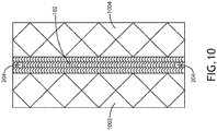
FIG. 10 is a front view of an exemplary embodiment of a first panel, a second panel, and at least one fastener strap according to the instant invention. -
FIG. 11 is an exploded top perspective view of the first panel, the second panel, and the at least one fastener strap ofFIG. 10 . -
FIG. 12 is a top perspective view of an exemplary embodiment of a first panel, a second panel, and two fastener straps according to instant invention. - Before explaining at least one embodiment of the instant invention disclosed herein in detail, it is to be understood that the invention is not limited in its application to the details of construction and the arrangement of the components or steps or methodologies set forth in the following description or illustrated in the drawings. In the following detailed description of embodiments of the invention, numerous specific details are set forth in order to provide a more thorough understanding of the invention. However, it will be apparent to one of ordinary skill in the art having the benefit of the instant disclosure that the invention disclosed herein may be practiced without these specific details. In other instances, well-known features may not be described in detail to avoid unnecessarily complicating the instant disclosure. The instant invention disclosed herein is capable of other embodiments or of being practiced or carried out in various ways. Also, it is to be understood that the phraseology and terminology employed herein is for the purpose of description and should not be regarded as limiting.
- As used herein a letter following a reference numeral is intended to reference an embodiment of the feature or element that may be similar, but not necessarily identical, to a previously described element or feature bearing the same reference numeral (e.g., 1, 1 a, 1b). Such shorthand notations are used for purposes of convenience only, and should not be construed to limit the instant invention in any way unless expressly stated to the contrary.
- Further, unless expressly stated to the contrary, "or" refers to an inclusive or and not to an exclusive or. For example, a condition A or B is satisfied by anyone of the following: A is true (or present) and B is false (or not present), A is false (or not present) and B is true (or present), and both A and B are true (or present).
- In addition, use of the "a" or "an" are employed to describe elements and components of embodiments of the instant invention. This is done merely for convenience and to give a general sense of the invention, and "a" and "an" are intended to include one or at least one and the singular also includes the plural unless it is obvious that it is meant otherwise.
- Finally, as used herein any reference to "one embodiment," or "some embodiments" means that a particular element, feature, structure, or characteristic described in connection with the embodiment is included in at least one embodiment of the invention disclosed herein. The appearances of the phrase "in some embodiments" in various places in the specification are not necessarily all referring to the same embodiment, and embodiments of the invention disclosed may include one or more of the features expressly described or inherently present herein, or any combination of sub-combination of two or more such features, along with any other features which may not necessarily be expressly described or inherently present in the instant disclosure.
- Broadly, embodiments of the instant invention disclosed herein are directed a method of creating and system of a load-transferring connection between structurally loaded components (e.g., composite shells or panels).
- Using standard fixing techniques, such as screw fasteners, creates stress raisers around these fasteners. Furthermore, in order to reduce these "point" fastener stress raises, a larger number of fasteners is required, increasing both assembly and disassembly time.
- The use of advanced materials and structures (e.g., a laminate or a composite shell comprising a composite sandwich structure including a lightweight foam material core sandwiched on either side with a composite skin (e.g., carbon, Kevlar, or Zylon)) is key to producing extremely lightweight, but exceptionally strong body-shell structures for products such as long-range, long-endurance drones and aircraft seating. The challenge lies in the assembly, disassembly and fixing of these extremely lightweight body-shell structures with equivalent strong and lightweight fastening solutions.
- Embodiments may include a connection (e.g., a fastener strap) that when installed can transfer structural loads from one loaded component (e.g., a composite shell or panel) to another loaded component, across edge interfaces of the loaded components. Such connection may not affect aerodynamics or a profile such that the connection would have a smooth and flush interface between the two or more loaded components (e.g., composite structural shells or laminates). Such connection may be easy to assemble and disassemble as compared to a typical line of rivets or fasteners. Such connection may deliver quick rig and de-rig capability.
- Embodiments may include a lightweight, part rigid, part flexible thin composite fastener strap that is able to sustain sideways loads when installed. The fastener strap may include two or more stiffening ribs, set apart from each other by a certain distance. Each stiffening rib locks into an equivalent single channel formed within each of two components (e.g., composite shell structures or panels) to be joined. An additional load-bearing structure (e.g., a support frame), when required, may support the joint from below or within, such that the support frame is contained within the two components (e.g., composite shell structures or panels) and the fastener strap. At each extremity of the strap are location points which can be counter-sunk to enable a single attachment means (e.g., fastener, a quick-release fastener, a screw, a pin, a bolt, a nut, a latch, and/or holes) to lie flush with the strap and outer surfaces of the components (e.g., composite shell structures or panels) to be joined and tie the fastener strap to the lower support-bearing structure (e.g., support frame). Embodiments may include a connection between structurally loaded components (e.g., composite shell structures or panels) that is capable of transferring compression and tension loads. Some Embodiments may allow for quick assembly and disassembly of subassemblies (e.g., vehicular or aircraft subassemblies). Additionally, embodiments may allow for continuity to an outer surface (e.g., a flushness across outers surfaces of two components and the fastener strap), that can be a key parameter for aerodynamic efficiency of aircraft exteriors and for cosmetic appearance and tribology wear & tear (e.g., from trolleys and passengers) in aircraft interiors.
- Embodiments may include a lightweight composite structure fastener strap. The fastener strap may include a double ribbed strap, by which the strap locks into channels of two components (e.g., composite shell structures or panels) by means of the ribs. These ribs may lock directly into channels that have been molded into or formed in the components (e.g., lightweight composite skins of composite shell structures or panels) that may butt up against an underlying load bearing structure (e.g., support frame). The composite, lightweight fastener strap may be flexible, such that fastener strap can be adapted through flexure to fit around lightweight composite skins and may immediately hold the two adjoining composite skins in place before the final attachment means (e.g., end fasteners) have been securely fixed. The entire fastener strap when fully fastened may lie flush with the other components being joined.
- Embodiments may include joining thin, lightweight composite shell-structures together in such a way that potentially high tensile and compressive loads can be evenly transmitted across the shell-structure joint without risk of joint or composite shell-structure failure. Furthermore, embodiments may also incorporate a lightweight, rapid assembly and disassembly method to quickly tie the composite shell-structures together as well as quickly release them, as and when required.
- The attachment means for fixing the fastener strap to the underlying load-bearing structure (e.g., support frame) may be provided by a quick-release fastener, a screw, a pin, a bolt, a nut, a latch, a lock mechanism, a rivet, a mechanical pin device, and/or holes.
- Embodiments may include the use of extremely strong and lightweight composite sandwich structures comprising a thin (e.g., 3mm) lightweight foam core sandwiched between two very thin (e.g., 0.3mm to 0.6mm) external skins (e.g, carbon-fibre, Kevlar, Zylon or equivalent composite skins) to form a structural body component that can be joined to another component via a fastener strap.
- Embodiments may include a means of rigidly joining together by butting up two components (e.g., composite shell structures or panels) with a minimal, quick release fastening solution, such that compressive and tensile loads can be evenly transmitted through the joint without any stress raisers being present.
- Embodiments may include the ability to quickly and flexibly access components such as electronic sub-systems (e.g., batteries, wiring, computing devices, sensors, antennas, and/or connectors) underneath outer skin shell-structures (e.g., a wing section or fuselage section) by means of a quick assembly and quick release fastening mechanism enabling at least one of potentially multiple molded composite sandwich structures to be removed quickly and easily. For example, the fastener strap may be installed in less than one minute to connect two components, and the fastener strap may be removed in less than one minute to disassemble two components.
- Embodiments may include providing attachment means coupled to a fastener strap, whereby the attachment means does not get easily dropped and get lost when working on the composite product in challenging environments. For example, the attachment means may be affixed to the fastener strap.
- Embodiments may include the fastener strap being able to provide a precise, robust, quick-release mechanism, for connecting very thin, lightweight composite sandwich structures.
- Embodiments may include the ability to ensure that a joint is successfully sealed such that water (or other fluid) ingress is suppressed or at least minimized.
- In some embodiments, the fastener strap may include a flexible section within the overall length of the fastener strap to enable the composite fastener strap to open up around a supporting structure (e.g., a wing-rib) and provide a natural clamping mechanism.
- Referring now to
FIG. 1 , an exemplary embodiment of adrone 100 according to the invention disclosed herein is depicted. Thedrone 100 may be composed of a plurality of composite shell components. For example, the assembly of a drone fuselage body and associated wing shells may be manufactured using a composite shell-structure technique. For example, thedrone 100 may include a fuselagecomposite shell 104, two wingcomposite shells 106, and two rotor assemblycomposite shells 108 havingrotors 110 attached thereto. Thedrone 100 may includefastener straps 102 that connect various of the composite shell components to one another. For example, the fuselagecomposite shell 104 may be connected to the two wingcomposite shells 106 via two fastener straps 102. For example, each of the two wingcomposite shells 106 may be connected to a rotor assemblycomposite shell 108 via afastener strap 102. The fastener straps 102 allow thedrone 100 to be quickly assembled and disassembled. When installed, the fastener straps 102 may evenly transmit compressive and tensile loads through joints with abutting composite shell components without any stress raisers being present. - Referring now to
FIG. 2 , an exemplary embodiment of afastener strap 102 according to the inventions disclosed herein is depicted. Thefastener strap 102 may include astrap section 202, at least one (e.g., two, as shown) firststiffening rib section 206, at least one (e.g., two, as shown) secondstiffening rib section 206, holes 204, abolt 210, and anut 212. In some embodiments, thefastener strap 102 may be made of carbon fibre, Kevlar, Zylon, or a combination thereof. - The at least one first
stiffening rib section 206 and the at least one secondstiffening rib section 206 may extend outwardly from a side (e.g., an inwardly facing side) of thestrap section 202. The at least one firststiffening rib section 206 and the at least one secondstiffening rib section 206 may extend longitudinally along portions of the side of thestrap section 202. The at least one firststiffening rib section 206 may be parallel to the at least one secondstiffening rib section 206. In some embodiments where there are two firststiffening rib sections 206 and two secondstiffening rib sections 206, there is a first gap between the two firststiffening rib sections 206 and a second gap between the two secondstiffening rib sections 206. The first gap and the second gap may be adjacently located along thefastener strap 102 at a moreflexible section 208, wherein thefastener strap 102 may be more flexible at locations along the first and second gaps than at locations located along the two firststiffening rib sections 206 and the two secondstiffening rib sections 206. For example, the first and second gaps may allow thefastener strap 102 to bend around corresponding curved sections (e.g., leading edges of wing sections) of first and second components (e.g., composite shell structures or panels) being joined. In some embodiments, the stiffeningrib sections 206 do not extend an entire length of thefastener strap 102; for example, aflexible section 208 of thefastener strap 102 may be rib-free. For example, theflexible section 208 may enable thefastener strap 102 to be slipped over a joint easily and quickly. Theflexible section 208 may act as a spring mechanism allowing the stiffeningrib sections 206 to lock with channels formed in the two to-be-joined components (e.g., composite shell-structure components), thus already locking the two components together prior to, for example, final quick-release fasteners, screws, pins, or bolt fasteners being tightened up. - In some embodiments, the stiffening
rib sections 206 may extend continuously and substantially (e.g., except for near the holes 204) the entire length of thefastener strap 102, for example, so that two panels (e.g., 1202, 1204) can be joined with two, oppositely installed fastening straps 102. - The
fastener strap 102 may include attachment means for securing first and second ends of thefastener strap 102 against a first component and the second component, as well as an underlying support frame (e.g., 304) (if any). For example, the attachment means may include a quick-release fastener, a screw, a pin, abolt 210, anut 212, a latch, a lock mechanism, a rivet, a mechanical pin device, and/or holes 204. Theholes 204 may be countersunk to accommodate quick-release fasteners, screws, pins, or bolts and so as to allow a quick-release fastener, a screw, a pin, abolt 210, anut 212, a latch, a lock mechanism, a rivet, and/or a mechanical pin device to be flush along an exterior surface of thefastener strap 102. - Referring now to
FIG. 3 , a cross-sectional view of an exemplary embodiment of afastener strap 102 connecting twocomponents 302 supported by asupport frame 304 according to the invention disclosed herein is depicted. - The two
components 302 may be any suitable components to be joined by thefastener strap 102. For example, the twocomponents 302 may be implemented as composite shell components or panels. For example, the twocomponents 302 may be vehicular components (e.g., aircraft components, train components, watercraft components, and/or automobile components). For example, the twocomponents 302 may be implemented as or include at least one fuselagecomposite shell 104, at least one wingcomposite shell 106, and/or at least one rotor assemblycomposite shell 108. For example, the twocomponents 302 may be implemented as aircraft interior panels, such as used for seating assemblies or wall panels in an aircraft. - The two
components 302 may abut each other or an interveningsupport frame 304. Thefastener strap 102 may fit over edges of the twocomponents 302 and/or thesupport frame 304. For example, thesupport frame 304 may support the edges of the twocomponents 302 and a middle portion of thestrap section 202 of thefastener strap 102. - A first of the two
components 302 may have a firststrap section channel 308 and at least one first stiffeningrib section channel 306 positioned along the firststrap section channel 308. The firststrap section channel 308 and the at least one first stiffeningrib section channel 306 may be positioned along at least one edge of thefirst component 302. The firststrap section channel 308 may be configured to receive a first portion of thestrap section 202 of thefastener strap 102. The at least one first stiffeningrib section channel 306 may be configured to receive the at least one firststiffening rib section 206 of thefastener strap 102. In some embodiments where there are two firststiffening rib sections 206 and two secondstiffening rib sections 206 on thefastener strap 102, thefirst component 302 includes two first stiffeningrib section channels 306 positioned along the firststrap section channel 308 with a first corresponding gap between the two first stiffeningrib section channels 306 such that the two first stiffeningrib section channels 306 may be configured to receive the two firststiffening rib sections 206 of thefastener strap 102. - A second of the two
components 302 may have a secondstrap section channel 308 and at least one second stiffeningrib section channel 306 positioned along the secondstrap section channel 308. The secondstrap section channel 308 and the at least one second stiffeningrib section channel 306 may be positioned along at least one edge of thesecond component 302. The secondstrap section channel 308 may be configured to receive a second portion of thestrap section 202 of thefastener strap 102. The at least one second stiffeningrib section channel 306 may be configured to receive the at least one secondstiffening rib section 206 of thefastener strap 102. In some embodiments where there are two firststiffening rib sections 206 and two secondstiffening rib sections 206 on thefastener strap 102, thesecond component 302 includes two second stiffeningrib section channels 306 positioned along the secondstrap section channel 308 with a second corresponding gap between the two second stiffeningrib section channels 306 such that the two second stiffeningrib section channels 306 may be configured to receive the two secondstiffening rib sections 206 of thefastener strap 102. - When the
fastener strap 102 is installed in the firststrap section channel 308, the at least one first stiffeningrib section channel 306, the secondstrap section channel 308, and the at least one second stiffeningrib section channel 306, a load-bearing connection is formed between thefirst component 302 and thesecond component 302. - Referring now to
FIG. 4 , a perspective view of an exemplary embodiment of asupport frame 304 according to the invention disclosed herein is depicted. For example, thesupport frame 304 depicted is a drone wing rib; however, any suitable support frame may be used for any suitable application. Thesupport frame 304 may include at least onehole 404 configured to accommodate a screw, a pin, abolt 210, a rivet, and/or a mechanical pin device of the attachment means. In some embodiments, the at least onehole 404 is threaded. Thesupport frame 304 may includeridges 402 configured to accommodate composite shells components (e.g., 104, 106, 108). Thesupport frame 304 may include a central opening where cables and wires can pass through a wing of adrone 100. - Referring now to
FIGS. 5-6 , perspective views of an exemplary embodiment of acomponent 302 according to the invention disclosed herein is depicted. For example, thecomponent 302 depicted is a wing composite shell (e.g., 106). Thecomponent 302 may include two stiffeningrib section channels 306 positioned along thestrap section channel 308. For example, the component may include a stiffeningrib section channel 306 on a top side of the wing composite shell (e.g., 106) and a stiffeningrib section channel 306 on the bottom side of the wing composite shell (e.g., 106). In some embodiments, the shape and configuration of thechannels channels fastener strap 102 is inserted into thechannels - Referring now to
FIG. 7 , a perspective cut-away view of an exemplary embodiment of acomponent 302, asupport frame 304, and afastener strap 102 according to the invention disclosed herein is depicted. For example, thecomponent 302 depicted is a wing composite shell (e.g., 106). - Referring now to
FIG. 8 , a perspective cut-away view of an exemplary embodiment of afirst component 302, a second component (e.g., fuselage composite shell 104), asupport frame 304, and afastener strap 102 according to the invention disclosed herein is depicted. For example, thecomponent 302 depicted is a wing composite shell (e.g., 106). Thefastener strap 102 may be configured to connect the first component (e.g., a wing composite shell (e.g., 106)) to the second component (e.g., fuselage composite shell 104). As shown, thefastener strap 102 may be flush with the exterior surfaces of the first component (e.g., a wing composite shell (e.g., 106)) and the second component (e.g., fuselage composite shell 104). - Referring now to
FIG. 9 , perspective views of an exemplary embodiment of afirst panel 902, asecond panel 904, and at least onefastener strap 102 implemented in an interior of an aircraft according to the invention disclosed herein are depicted. Thepanels panel 902 may be a wall panel. For example, thepanel 904 may be a panel of an aircraft seating assembly. For example, thepanels - For example, the
panels fastener straps 102 may be configured to connect thepanel 902 to thepanel 904. For example, a first fastener strap 102 (shown) may be installed inchannels panels channels panels panels fastener strap 102 is installed in thechannels second fastener strap 102 is similarly installed on thepanels panels - Referring now to
FIGS. 10-11 , a front view and an exploded top perspective view of an exemplary embodiment of afirst panel 1002, asecond panel 1004, and at least onefastener strap 102 according to the invention disclosed herein are depicted. When thefastener strap 102 is installed in on thepanels panels - Referring now to
FIG. 12 , a top perspective view of an exemplary embodiment of afirst panel 1202, asecond panel 1204, and twofastener straps 102 according to the invention disclosed herein is depicted. The twofastener straps 102 may be configured to connect thepanel 1202 to thepanel 1204. For example, afirst fastener strap 102 may be installed inchannels panels second fastener strap 102 may be installed inchannels panels second fastener strap 102 may be installed on opposite sides of thepanels first fastener strap 102. When the fastener straps 102 are installed on thepanels panels - As will be appreciated from the above, embodiments of the invention disclosed herein may be directed to a method of creating and system of a load-transferring connection between structurally loaded components (e.g., composite shells or panels).
- As used throughout, "at least one" means one or a plurality of; for example, "at least one" may comprise one, two, three, ..., one hundred, or more. Similarly, as used throughout, "one or more" means one or a plurality of; for example, "one or more" may comprise one, two, three, ..., one hundred, or more. Further, as used throughout, "zero or more" means zero, one, or a plurality of; for example, "zero or more" may comprise zero, one, two, three, ..., one hundred, or more.
- In the present disclosure, the methods, operations, and/or functionality disclosed may be implemented as sets of instructions or software readable by a device. Further, it is understood that the specific order or hierarchy of steps in the methods, operations, and/or functionality disclosed are examples of exemplary approaches. Based upon design preferences, it is understood that the specific order or hierarchy of steps in the methods, operations, and/or functionality can be rearranged while remaining within the scope of the invention disclosed herein.
- It is to be understood that embodiments of the methods according to the invention disclosed herein may include one or more of the steps described herein. Further, such steps may be carried out in any desired order and two or more of the steps may be carried out simultaneously with one another. Two or more of the steps disclosed herein may be combined in a single step, and in some embodiments, one or more of the steps may be carried out as two or more sub-steps. Further, other steps or sub-steps may be carried in addition to, or as substitutes to one or more of the steps disclosed herein.
- From the above description, it is clear that the instant invention disclosed herein is well adapted to carry out the objects and to attain the advantages mentioned herein as well as those inherent in the invention disclosed herein. While presently preferred embodiments of the invention disclosed herein have been described for purposes of this disclosure, it will be understood that numerous changes may be made which will readily suggest themselves to those skilled in the art and which are accomplished within the broad scope and coverage of the invention defined by the appendant claims.
Claims (15)
- A system, comprising:a fastener strap (102) comprising a strap section (202), at least one first stiffening rib section (206), and at least one second stiffening rib section (206), the at least one first stiffening rib section (206) and the at least one second stiffening rib section (206) extending outwardly from a side of the strap section (202), the at least one first stiffening rib section (206) and the at least one second stiffening rib section (206) extending longitudinally along portions of the side of the strap section (202), the at least one first stiffening rib section (206) being parallel to the at least one second stiffening rib section (206);a first component (104, 106, 302, 902, 1002, 1202) comprising a first strap section channel (308) and at least one first stiffening rib section channel (306) positioned along the first strap section channel (308), the first strap section channel (308) and the at least one first stiffening rib section channel (306) positioned along at least one edge of the first component (104, 106, 302, 902, 1002, 1202), the first strap section channel (308) configured to receive a first portion of the strap section (202) of the fastener strap (102), the at least one first stiffening rib section channel (306) configured to receive the at least one first stiffening rib section (206) of the fastener strap (102); anda second component (104, 302, 904, 1004, 1204) comprising a second strap section channel and at least one second stiffening rib section channel (306) positioned along the second strap section channel (308), the second strap section channel (308) and the at least one second stiffening rib section channel (306) positioned along at least one edge of the second component (104, 302, 904, 1004, 1204), the second strap section channel (308) configured to receive a second portion of the strap section (202) of the fastener strap (102), the at least one second stiffening rib section channel (306) configured to receive the at least one second stiffening rib section (206) of the fastener strap (102),wherein, when the fastener strap (102) is installed in the first strap section channel (308), the at least one first stiffening rib section channel (306), the second strap section channel (308), and the at least one second stiffening rib section channel (306), a load-bearing connection is formed between the first component (104, 106, 302, 902, 1002, 1202) and the second component (104, 302, 904, 1004, 1204).
- The system according to claim 1, further comprising attachment means (204, 210, 212, 404) configured to secure first and second ends of the fastener strap (102) against the first component (104, 106, 302, 902, 1002, 1202) and the second component (104, 302, 904, 1004, 1204).
- The system according to claim 1 or 2, wherein the at least one first stiffening rib section (206) comprises two first stiffening rib sections (206) with a first gap between the two first stiffening rib sections (206), wherein the at least one second stiffening rib section (206) comprises two second stiffening rib sections (206) with a second gap between the two second stiffening rib sections (206), wherein the first gap and the second gap are adjacently located along the fastener strap (102), wherein the fastener strap (102) is more flexible at locations along the first and second gaps than at locations located along the two first stiffening rib sections (206) and the two second stiffening rib sections (206).
- The system according to claim 3, wherein the first and second gaps allow the fastener strap (102) to bend around corresponding curved sections of the first and second components (104, 106, 302, 902, 904, 1002, 1004, 1202, 1204).
- The system according to one or more of claims 1-4, further comprising a support frame (304), the support frame (304) abutting a portion of the first component (104, 106, 302, 902, 1002, 1202) and a portion of the second component (104, 302, 904, 1004, 1204), the support frame (304) configured to support a middle portion of the strap section (202) of the fastener strap (102).
- The system according to one or more of claims 1-5, wherein the first component (104, 106, 302, 902, 1002, 1202) and the second components (104, 302, 904, 1004, 1204) are vehicular components.
- The system according to one of claims claim 1-6, wherein the first component (104, 106, 302, 902, 1002, 1202) and the second components (104, 302, 904, 1004, 1204) are aircraft components.
- The system according to one or more of claims 1-7, wherein the first component (104, 106, 302, 902, 1002, 1202) and the second component (104, 302, 904, 1004, 1204) are composite shells.
- The system according to one or more of claims 1-8, wherein the first component is a wing composite shell (106), a fuselage composite shell (104), or a rotor section of a drone (100).
- The system according to one or more of claims 1-9, wherein the first component is a wing composite shell (106) and the second component is a fuselage composite shell (104).
- The system according to one or more of claims 1-10, wherein at least one of the first component and the second component is an aircraft interior panel.
- The system according to one or more of claims 1-11, wherein at least one of the first component and the second component is a panel (902, 904, 1002, 1004, 1202, 1204).
- The system according to one or more of claims 1-12, further comprising a second fastener strap (102) installed on the first and second components (104, 106, 302, 902, 904, 1002, 1004, 1202, 1204), the second fastener strap (102) installed on opposite sides of the first and second components (104, 106, 302, 902, 904, 1002, 1004, 1202, 1204), as the fastener strap (102).
- The system according to one or more of claims 1-13, wherein the first component is a panel (902, 1002, 1202) and comprising a second fastener strap (102) installed on the panel (902, 1002, 1202) and the second component (104, 302, 904, 1004, 1204), the second fastener strap (102) installed on opposite sides of the panel (902, 1002, 1202) and the second component (104, 302, 904, 1004, 1204) as the fastener strap (102),
wherein, when the fastener strap (102) is installed in the first strap section channel (308), the at least one first stiffening rib section channel (306), the second strap section channel (308), and the at least one second stiffening rib section channel (306) and when the second fastener strap (102) is installed on the panel (902, 1002, 1202) and the second component (104, 302, 904, 1004, 1204), a load-bearing connection is formed between the panel (902, 1002, 1202) and the component (104, 302, 904, 1004, 1204). - The system according to one or more of claims 1-14, wherein the first component is an aircraft interior panel (902, 1002, 1202), and/or wherein the second component is a second panel (904, 1004, 1204).
Applications Claiming Priority (2)
| Application Number | Priority Date | Filing Date | Title |
|---|---|---|---|
| US201862683495P | 2018-06-11 | 2018-06-11 | |
| US16/029,074 US11149770B2 (en) | 2018-06-11 | 2018-07-06 | Load-transferring connection between structurally loaded components |
Publications (2)
| Publication Number | Publication Date |
|---|---|
| EP3581483A1 true EP3581483A1 (en) | 2019-12-18 |
| EP3581483B1 EP3581483B1 (en) | 2021-05-12 |
Family
ID=67105679
Family Applications (1)
| Application Number | Title | Priority Date | Filing Date |
|---|---|---|---|
| EP19178536.9A Active EP3581483B1 (en) | 2018-06-11 | 2019-06-05 | Load-transferring connection between structurally loaded components |
Country Status (3)
| Country | Link |
|---|---|
| US (1) | US11149770B2 (en) |
| EP (1) | EP3581483B1 (en) |
| CN (1) | CN110576961B (en) |
Families Citing this family (3)
| Publication number | Priority date | Publication date | Assignee | Title |
|---|---|---|---|---|
| FR3099915A1 (en) * | 2019-08-13 | 2021-02-19 | Airbus Operations | Front part of the nacelle of an aircraft propulsion unit, the air inlet lip of which is linked to the outer panel by interlocking |
| US11161592B2 (en) * | 2019-09-11 | 2021-11-02 | Textron Innovations Inc. | Torque box sleeves for aircraft wing assemblies |
| CN113612009B (en) * | 2021-08-03 | 2023-05-09 | 中国电子科技集团公司第三十八研究所 | An Airborne Conformal Bearing Antenna |
Citations (5)
| Publication number | Priority date | Publication date | Assignee | Title |
|---|---|---|---|---|
| US4120998A (en) * | 1977-02-03 | 1978-10-17 | Northrop Corporation | Composite structure |
| WO2009083262A2 (en) * | 2007-12-30 | 2009-07-09 | Airbus Deutschland Gmbh | Wing-fuselage structural component for the connection of two airfoils and a fuselage section on an aircraft |
| US20140353426A1 (en) * | 2013-05-29 | 2014-12-04 | Airbus Operations (Sas) | Aircraft comprising an improved connection zone between a front beam and a front lower fuselage section |
| EP3199455A1 (en) * | 2016-01-29 | 2017-08-02 | AIRBUS HELICOPTERS DEUTSCHLAND GmbH | Rotary aircraft with an interface frame joining the fuselage tail boom and the tail cone |
| US20180141659A1 (en) * | 2016-11-21 | 2018-05-24 | Yevgeniy Il'ich Sher | Composite material and aircraft improvements |
Family Cites Families (17)
| Publication number | Priority date | Publication date | Assignee | Title |
|---|---|---|---|---|
| US3002717A (en) * | 1960-01-12 | 1961-10-03 | Pavlecka John | Airfoil structure |
| US3417529A (en) * | 1966-10-19 | 1968-12-24 | Panelfab Products Inc | Drive cleat connector |
| US3348459A (en) * | 1967-01-03 | 1967-10-24 | Harvey Aluminum Inc | Interlocking matting and coupling bar therefor |
| US3640039A (en) * | 1969-05-05 | 1972-02-08 | Ball Corp | Building structure |
| US3625549A (en) * | 1970-02-09 | 1971-12-07 | Gerrit De Vries | Strap ring connector |
| JPH08128420A (en) * | 1994-10-31 | 1996-05-21 | N I Shi Auto Tec Kk | Connecting member |
| SE514645C2 (en) * | 1998-10-06 | 2001-03-26 | Perstorp Flooring Ab | Floor covering material comprising disc-shaped floor elements intended to be joined by separate joint profiles |
| SE517009C2 (en) * | 1999-07-05 | 2002-04-02 | Perstorp Flooring Ab | Floor element with controls |
| SE522860C2 (en) * | 2000-03-10 | 2004-03-09 | Pergo Europ Ab | Vertically joined floor elements comprising a combination of different floor elements |
| US7665264B1 (en) * | 2001-02-20 | 2010-02-23 | Wolfe Michael J | Metal-faced building panels having angled projections in longitudinal edge recesses for mating with locking ramps on flanges of concealed I-shaped connector |
| AT410815B (en) * | 2001-04-05 | 2003-08-25 | Kaindl M | CONNECTION OF PANEL-SHAPED COMPONENTS |
| DE10243196B4 (en) * | 2002-09-18 | 2007-03-22 | Kaindl Flooring Gmbh | Panels with connection bracket |
| US20060059822A1 (en) * | 2004-08-04 | 2006-03-23 | Guffey James K | Deck clip |
| AU2011261174B2 (en) * | 2010-06-02 | 2017-01-05 | Ikan Building Systems Pty Ltd | Panel connection assembly, building panel and building construction method utilising a panel connection assembly |
| US9322421B2 (en) * | 2011-04-13 | 2016-04-26 | Geoffrey Alan Baker | Spring-loaded split-tongue connector system |
| US11181133B2 (en) * | 2015-05-11 | 2021-11-23 | Charles Beaulieu | Fastening device template |
| CA3023489C (en) * | 2016-05-11 | 2023-12-19 | Bombardier Inc. | Isolation mount |
-
2018
- 2018-07-06 US US16/029,074 patent/US11149770B2/en active Active
-
2019
- 2019-06-05 EP EP19178536.9A patent/EP3581483B1/en active Active
- 2019-06-11 CN CN201910498967.XA patent/CN110576961B/en active Active
Patent Citations (5)
| Publication number | Priority date | Publication date | Assignee | Title |
|---|---|---|---|---|
| US4120998A (en) * | 1977-02-03 | 1978-10-17 | Northrop Corporation | Composite structure |
| WO2009083262A2 (en) * | 2007-12-30 | 2009-07-09 | Airbus Deutschland Gmbh | Wing-fuselage structural component for the connection of two airfoils and a fuselage section on an aircraft |
| US20140353426A1 (en) * | 2013-05-29 | 2014-12-04 | Airbus Operations (Sas) | Aircraft comprising an improved connection zone between a front beam and a front lower fuselage section |
| EP3199455A1 (en) * | 2016-01-29 | 2017-08-02 | AIRBUS HELICOPTERS DEUTSCHLAND GmbH | Rotary aircraft with an interface frame joining the fuselage tail boom and the tail cone |
| US20180141659A1 (en) * | 2016-11-21 | 2018-05-24 | Yevgeniy Il'ich Sher | Composite material and aircraft improvements |
Also Published As
| Publication number | Publication date |
|---|---|
| US20190376541A1 (en) | 2019-12-12 |
| US11149770B2 (en) | 2021-10-19 |
| EP3581483B1 (en) | 2021-05-12 |
| CN110576961A (en) | 2019-12-17 |
| CN110576961B (en) | 2022-03-15 |
Similar Documents
| Publication | Publication Date | Title |
|---|---|---|
| EP2824030B1 (en) | Apparatus and methods for joining composite structures of aircrafts | |
| EP2730498B1 (en) | Joint for composite wings | |
| RU2649839C2 (en) | Vertically built-in stiffeners | |
| US7712993B2 (en) | Double shear joint for bonding in structural applications | |
| US8408493B2 (en) | Composite stringer end trim | |
| US8715808B2 (en) | Method for coupling stiffening profile elements and structural component | |
| EP3581483B1 (en) | Load-transferring connection between structurally loaded components | |
| US8985512B1 (en) | Aircraft, fuselages, and associated methods | |
| US9126670B2 (en) | Panel assembly and method of making the same | |
| CN104229119B (en) | Lower contact between the outside wing box and center wing panel of aircraft wing assemblies | |
| EP3312441B1 (en) | Panel fastening system | |
| US9517833B2 (en) | Apparatuses and methods for manufacturing a structure | |
| US9126672B2 (en) | Access door assembly and method of making the same | |
| US8356773B2 (en) | Structural wing-fuselage component for connecting two wings to a fuselage section of an aircraft | |
| CA3007566A1 (en) | Joint assembly and method of assembling same | |
| US20110168842A1 (en) | Joining system between linings and the structural elements that support them | |
| CN115610639B (en) | A method for quick installation, locking, and disassembly of the tail boom of an unmanned helicopter | |
| CN115743521B (en) | A quick-detachable tail boom for unmanned helicopters | |
| BR102020000716B1 (en) | COMPOSITE RIBBON AND METHOD FOR ASSEMBLY OF A COMPOSITE RIBBON | |
| KR20210003734A (en) | Composite structural element |
Legal Events
| Date | Code | Title | Description |
|---|---|---|---|
| PUAI | Public reference made under article 153(3) epc to a published international application that has entered the european phase |
Free format text: ORIGINAL CODE: 0009012 |
|
| STAA | Information on the status of an ep patent application or granted ep patent |
Free format text: STATUS: THE APPLICATION HAS BEEN PUBLISHED |
|
| AK | Designated contracting states |
Kind code of ref document: A1 Designated state(s): AL AT BE BG CH CY CZ DE DK EE ES FI FR GB GR HR HU IE IS IT LI LT LU LV MC MK MT NL NO PL PT RO RS SE SI SK SM TR |
|
| AX | Request for extension of the european patent |
Extension state: BA ME |
|
| STAA | Information on the status of an ep patent application or granted ep patent |
Free format text: STATUS: REQUEST FOR EXAMINATION WAS MADE |
|
| 17P | Request for examination filed |
Effective date: 20200616 |
|
| RBV | Designated contracting states (corrected) |
Designated state(s): AL AT BE BG CH CY CZ DE DK EE ES FI FR GB GR HR HU IE IS IT LI LT LU LV MC MK MT NL NO PL PT RO RS SE SI SK SM TR |
|
| GRAP | Despatch of communication of intention to grant a patent |
Free format text: ORIGINAL CODE: EPIDOSNIGR1 |
|
| STAA | Information on the status of an ep patent application or granted ep patent |
Free format text: STATUS: GRANT OF PATENT IS INTENDED |
|
| INTG | Intention to grant announced |
Effective date: 20201209 |
|
| GRAS | Grant fee paid |
Free format text: ORIGINAL CODE: EPIDOSNIGR3 |
|
| GRAA | (expected) grant |
Free format text: ORIGINAL CODE: 0009210 |
|
| STAA | Information on the status of an ep patent application or granted ep patent |
Free format text: STATUS: THE PATENT HAS BEEN GRANTED |
|
| AK | Designated contracting states |
Kind code of ref document: B1 Designated state(s): AL AT BE BG CH CY CZ DE DK EE ES FI FR GB GR HR HU IE IS IT LI LT LU LV MC MK MT NL NO PL PT RO RS SE SI SK SM TR |
|
| REG | Reference to a national code |
Ref country code: GB Ref legal event code: FG4D |
|
| REG | Reference to a national code |
Ref country code: CH Ref legal event code: EP |
|
| REG | Reference to a national code |
Ref country code: DE Ref legal event code: R096 Ref document number: 602019004548 Country of ref document: DE |
|
| REG | Reference to a national code |
Ref country code: IE Ref legal event code: FG4D |
|
| REG | Reference to a national code |
Ref country code: AT Ref legal event code: REF Ref document number: 1392035 Country of ref document: AT Kind code of ref document: T Effective date: 20210615 |
|
| REG | Reference to a national code |
Ref country code: LT Ref legal event code: MG9D |
|
| REG | Reference to a national code |
Ref country code: AT Ref legal event code: MK05 Ref document number: 1392035 Country of ref document: AT Kind code of ref document: T Effective date: 20210512 |
|
| REG | Reference to a national code |
Ref country code: NL Ref legal event code: MP Effective date: 20210512 |
|
| PG25 | Lapsed in a contracting state [announced via postgrant information from national office to epo] |
Ref country code: AT Free format text: LAPSE BECAUSE OF FAILURE TO SUBMIT A TRANSLATION OF THE DESCRIPTION OR TO PAY THE FEE WITHIN THE PRESCRIBED TIME-LIMIT Effective date: 20210512 Ref country code: BG Free format text: LAPSE BECAUSE OF FAILURE TO SUBMIT A TRANSLATION OF THE DESCRIPTION OR TO PAY THE FEE WITHIN THE PRESCRIBED TIME-LIMIT Effective date: 20210812 Ref country code: FI Free format text: LAPSE BECAUSE OF FAILURE TO SUBMIT A TRANSLATION OF THE DESCRIPTION OR TO PAY THE FEE WITHIN THE PRESCRIBED TIME-LIMIT Effective date: 20210512 Ref country code: LT Free format text: LAPSE BECAUSE OF FAILURE TO SUBMIT A TRANSLATION OF THE DESCRIPTION OR TO PAY THE FEE WITHIN THE PRESCRIBED TIME-LIMIT Effective date: 20210512 Ref country code: HR Free format text: LAPSE BECAUSE OF FAILURE TO SUBMIT A TRANSLATION OF THE DESCRIPTION OR TO PAY THE FEE WITHIN THE PRESCRIBED TIME-LIMIT Effective date: 20210512 |
|
| PG25 | Lapsed in a contracting state [announced via postgrant information from national office to epo] |
Ref country code: IS Free format text: LAPSE BECAUSE OF FAILURE TO SUBMIT A TRANSLATION OF THE DESCRIPTION OR TO PAY THE FEE WITHIN THE PRESCRIBED TIME-LIMIT Effective date: 20210912 Ref country code: GR Free format text: LAPSE BECAUSE OF FAILURE TO SUBMIT A TRANSLATION OF THE DESCRIPTION OR TO PAY THE FEE WITHIN THE PRESCRIBED TIME-LIMIT Effective date: 20210813 Ref country code: RS Free format text: LAPSE BECAUSE OF FAILURE TO SUBMIT A TRANSLATION OF THE DESCRIPTION OR TO PAY THE FEE WITHIN THE PRESCRIBED TIME-LIMIT Effective date: 20210512 Ref country code: PT Free format text: LAPSE BECAUSE OF FAILURE TO SUBMIT A TRANSLATION OF THE DESCRIPTION OR TO PAY THE FEE WITHIN THE PRESCRIBED TIME-LIMIT Effective date: 20210913 Ref country code: SE Free format text: LAPSE BECAUSE OF FAILURE TO SUBMIT A TRANSLATION OF THE DESCRIPTION OR TO PAY THE FEE WITHIN THE PRESCRIBED TIME-LIMIT Effective date: 20210512 Ref country code: PL Free format text: LAPSE BECAUSE OF FAILURE TO SUBMIT A TRANSLATION OF THE DESCRIPTION OR TO PAY THE FEE WITHIN THE PRESCRIBED TIME-LIMIT Effective date: 20210512 Ref country code: NO Free format text: LAPSE BECAUSE OF FAILURE TO SUBMIT A TRANSLATION OF THE DESCRIPTION OR TO PAY THE FEE WITHIN THE PRESCRIBED TIME-LIMIT Effective date: 20210812 Ref country code: LV Free format text: LAPSE BECAUSE OF FAILURE TO SUBMIT A TRANSLATION OF THE DESCRIPTION OR TO PAY THE FEE WITHIN THE PRESCRIBED TIME-LIMIT Effective date: 20210512 |
|
| PG25 | Lapsed in a contracting state [announced via postgrant information from national office to epo] |
Ref country code: NL Free format text: LAPSE BECAUSE OF FAILURE TO SUBMIT A TRANSLATION OF THE DESCRIPTION OR TO PAY THE FEE WITHIN THE PRESCRIBED TIME-LIMIT Effective date: 20210512 |
|
| PG25 | Lapsed in a contracting state [announced via postgrant information from national office to epo] |
Ref country code: RO Free format text: LAPSE BECAUSE OF FAILURE TO SUBMIT A TRANSLATION OF THE DESCRIPTION OR TO PAY THE FEE WITHIN THE PRESCRIBED TIME-LIMIT Effective date: 20210512 Ref country code: SM Free format text: LAPSE BECAUSE OF FAILURE TO SUBMIT A TRANSLATION OF THE DESCRIPTION OR TO PAY THE FEE WITHIN THE PRESCRIBED TIME-LIMIT Effective date: 20210512 Ref country code: CZ Free format text: LAPSE BECAUSE OF FAILURE TO SUBMIT A TRANSLATION OF THE DESCRIPTION OR TO PAY THE FEE WITHIN THE PRESCRIBED TIME-LIMIT Effective date: 20210512 Ref country code: DK Free format text: LAPSE BECAUSE OF FAILURE TO SUBMIT A TRANSLATION OF THE DESCRIPTION OR TO PAY THE FEE WITHIN THE PRESCRIBED TIME-LIMIT Effective date: 20210512 Ref country code: ES Free format text: LAPSE BECAUSE OF FAILURE TO SUBMIT A TRANSLATION OF THE DESCRIPTION OR TO PAY THE FEE WITHIN THE PRESCRIBED TIME-LIMIT Effective date: 20210512 Ref country code: EE Free format text: LAPSE BECAUSE OF FAILURE TO SUBMIT A TRANSLATION OF THE DESCRIPTION OR TO PAY THE FEE WITHIN THE PRESCRIBED TIME-LIMIT Effective date: 20210512 Ref country code: SK Free format text: LAPSE BECAUSE OF FAILURE TO SUBMIT A TRANSLATION OF THE DESCRIPTION OR TO PAY THE FEE WITHIN THE PRESCRIBED TIME-LIMIT Effective date: 20210512 |
|
| REG | Reference to a national code |
Ref country code: DE Ref legal event code: R097 Ref document number: 602019004548 Country of ref document: DE |
|
| REG | Reference to a national code |
Ref country code: BE Ref legal event code: MM Effective date: 20210630 |
|
| PLBE | No opposition filed within time limit |
Free format text: ORIGINAL CODE: 0009261 |
|
| STAA | Information on the status of an ep patent application or granted ep patent |
Free format text: STATUS: NO OPPOSITION FILED WITHIN TIME LIMIT |
|
| PG25 | Lapsed in a contracting state [announced via postgrant information from national office to epo] |
Ref country code: MC Free format text: LAPSE BECAUSE OF FAILURE TO SUBMIT A TRANSLATION OF THE DESCRIPTION OR TO PAY THE FEE WITHIN THE PRESCRIBED TIME-LIMIT Effective date: 20210512 Ref country code: LU Free format text: LAPSE BECAUSE OF NON-PAYMENT OF DUE FEES Effective date: 20210605 |
|
| 26N | No opposition filed |
Effective date: 20220215 |
|
| PG25 | Lapsed in a contracting state [announced via postgrant information from national office to epo] |
Ref country code: IE Free format text: LAPSE BECAUSE OF NON-PAYMENT OF DUE FEES Effective date: 20210605 |
|
| PG25 | Lapsed in a contracting state [announced via postgrant information from national office to epo] |
Ref country code: IS Free format text: LAPSE BECAUSE OF FAILURE TO SUBMIT A TRANSLATION OF THE DESCRIPTION OR TO PAY THE FEE WITHIN THE PRESCRIBED TIME-LIMIT Effective date: 20210912 Ref country code: AL Free format text: LAPSE BECAUSE OF FAILURE TO SUBMIT A TRANSLATION OF THE DESCRIPTION OR TO PAY THE FEE WITHIN THE PRESCRIBED TIME-LIMIT Effective date: 20210512 |
|
| PG25 | Lapsed in a contracting state [announced via postgrant information from national office to epo] |
Ref country code: IT Free format text: LAPSE BECAUSE OF FAILURE TO SUBMIT A TRANSLATION OF THE DESCRIPTION OR TO PAY THE FEE WITHIN THE PRESCRIBED TIME-LIMIT Effective date: 20210512 Ref country code: BE Free format text: LAPSE BECAUSE OF NON-PAYMENT OF DUE FEES Effective date: 20210630 |
|
| REG | Reference to a national code |
Ref country code: CH Ref legal event code: PL |
|
| PG25 | Lapsed in a contracting state [announced via postgrant information from national office to epo] |
Ref country code: LI Free format text: LAPSE BECAUSE OF NON-PAYMENT OF DUE FEES Effective date: 20220630 Ref country code: CH Free format text: LAPSE BECAUSE OF NON-PAYMENT OF DUE FEES Effective date: 20220630 |
|
| PG25 | Lapsed in a contracting state [announced via postgrant information from national office to epo] |
Ref country code: CY Free format text: LAPSE BECAUSE OF FAILURE TO SUBMIT A TRANSLATION OF THE DESCRIPTION OR TO PAY THE FEE WITHIN THE PRESCRIBED TIME-LIMIT Effective date: 20210512 |
|
| PG25 | Lapsed in a contracting state [announced via postgrant information from national office to epo] |
Ref country code: HU Free format text: LAPSE BECAUSE OF FAILURE TO SUBMIT A TRANSLATION OF THE DESCRIPTION OR TO PAY THE FEE WITHIN THE PRESCRIBED TIME-LIMIT; INVALID AB INITIO Effective date: 20190605 |
|
| PG25 | Lapsed in a contracting state [announced via postgrant information from national office to epo] |
Ref country code: MK Free format text: LAPSE BECAUSE OF FAILURE TO SUBMIT A TRANSLATION OF THE DESCRIPTION OR TO PAY THE FEE WITHIN THE PRESCRIBED TIME-LIMIT Effective date: 20210512 |
|
| PG25 | Lapsed in a contracting state [announced via postgrant information from national office to epo] |
Ref country code: MT Free format text: LAPSE BECAUSE OF FAILURE TO SUBMIT A TRANSLATION OF THE DESCRIPTION OR TO PAY THE FEE WITHIN THE PRESCRIBED TIME-LIMIT Effective date: 20210512 |
|
| PGFP | Annual fee paid to national office [announced via postgrant information from national office to epo] |
Ref country code: DE Payment date: 20250520 Year of fee payment: 7 |
|
| PGFP | Annual fee paid to national office [announced via postgrant information from national office to epo] |
Ref country code: GB Payment date: 20250520 Year of fee payment: 7 |
|
| PGFP | Annual fee paid to national office [announced via postgrant information from national office to epo] |
Ref country code: FR Payment date: 20250521 Year of fee payment: 7 |
|
| PG25 | Lapsed in a contracting state [announced via postgrant information from national office to epo] |
Ref country code: TR Free format text: LAPSE BECAUSE OF FAILURE TO SUBMIT A TRANSLATION OF THE DESCRIPTION OR TO PAY THE FEE WITHIN THE PRESCRIBED TIME-LIMIT Effective date: 20210512 |