EP3581421B1 - Tractor with bypass group for stationary steering - Google Patents
Tractor with bypass group for stationary steering Download PDFInfo
- Publication number
- EP3581421B1 EP3581421B1 EP19178189.7A EP19178189A EP3581421B1 EP 3581421 B1 EP3581421 B1 EP 3581421B1 EP 19178189 A EP19178189 A EP 19178189A EP 3581421 B1 EP3581421 B1 EP 3581421B1
- Authority
- EP
- European Patent Office
- Prior art keywords
- tractor
- engine
- hydraulic
- pump
- hydraulic line
- Prior art date
- Legal status (The legal status is an assumption and is not a legal conclusion. Google has not performed a legal analysis and makes no representation as to the accuracy of the status listed.)
- Active
Links
Images


Classifications
-
- B—PERFORMING OPERATIONS; TRANSPORTING
- B60—VEHICLES IN GENERAL
- B60K—ARRANGEMENT OR MOUNTING OF PROPULSION UNITS OR OF TRANSMISSIONS IN VEHICLES; ARRANGEMENT OR MOUNTING OF PLURAL DIVERSE PRIME-MOVERS IN VEHICLES; AUXILIARY DRIVES FOR VEHICLES; INSTRUMENTATION OR DASHBOARDS FOR VEHICLES; ARRANGEMENTS IN CONNECTION WITH COOLING, AIR INTAKE, GAS EXHAUST OR FUEL SUPPLY OF PROPULSION UNITS IN VEHICLES
- B60K17/00—Arrangement or mounting of transmissions in vehicles
- B60K17/04—Arrangement or mounting of transmissions in vehicles characterised by arrangement, location or kind of gearing
- B60K17/10—Arrangement or mounting of transmissions in vehicles characterised by arrangement, location or kind of gearing of fluid gearing
-
- B—PERFORMING OPERATIONS; TRANSPORTING
- B60—VEHICLES IN GENERAL
- B60K—ARRANGEMENT OR MOUNTING OF PROPULSION UNITS OR OF TRANSMISSIONS IN VEHICLES; ARRANGEMENT OR MOUNTING OF PLURAL DIVERSE PRIME-MOVERS IN VEHICLES; AUXILIARY DRIVES FOR VEHICLES; INSTRUMENTATION OR DASHBOARDS FOR VEHICLES; ARRANGEMENTS IN CONNECTION WITH COOLING, AIR INTAKE, GAS EXHAUST OR FUEL SUPPLY OF PROPULSION UNITS IN VEHICLES
- B60K17/00—Arrangement or mounting of transmissions in vehicles
- B60K17/34—Arrangement or mounting of transmissions in vehicles for driving both front and rear wheels, e.g. four wheel drive vehicles
- B60K17/356—Arrangement or mounting of transmissions in vehicles for driving both front and rear wheels, e.g. four wheel drive vehicles having fluid or electric motor, for driving one or more wheels
-
- B—PERFORMING OPERATIONS; TRANSPORTING
- B60—VEHICLES IN GENERAL
- B60W—CONJOINT CONTROL OF VEHICLE SUB-UNITS OF DIFFERENT TYPE OR DIFFERENT FUNCTION; CONTROL SYSTEMS SPECIALLY ADAPTED FOR HYBRID VEHICLES; ROAD VEHICLE DRIVE CONTROL SYSTEMS FOR PURPOSES NOT RELATED TO THE CONTROL OF A PARTICULAR SUB-UNIT
- B60W2540/00—Input parameters relating to occupants
- B60W2540/18—Steering angle
-
- B—PERFORMING OPERATIONS; TRANSPORTING
- B60—VEHICLES IN GENERAL
- B60Y—INDEXING SCHEME RELATING TO ASPECTS CROSS-CUTTING VEHICLE TECHNOLOGY
- B60Y2200/00—Type of vehicle
- B60Y2200/20—Off-Road Vehicles
- B60Y2200/22—Agricultural vehicles
- B60Y2200/221—Tractors
-
- B—PERFORMING OPERATIONS; TRANSPORTING
- B60—VEHICLES IN GENERAL
- B60Y—INDEXING SCHEME RELATING TO ASPECTS CROSS-CUTTING VEHICLE TECHNOLOGY
- B60Y2200/00—Type of vehicle
- B60Y2200/40—Special vehicles
- B60Y2200/41—Construction vehicles, e.g. graders, excavators
- B60Y2200/417—Articulated frame vehicles
Definitions
- the present invention relates to a tractor with a bypass group for stationary steering.
- the tractor allows covering very large areas with a significant flexibility of use.
- Four-wheel drive tractors formed by a front frame and a rear frame hinged to each other in a fulcrum, are commonly used.
- the rotation axis of the front frame with respect to the rear frame is at said fulcrum, at a distance X 1 from the front axle of the front wheels, which is different from distance X 2 of the rotation axis from the rear axle of the rear wheels.
- the front wheels are driven by a front engine supplied by a hydraulic pump which also supplies a rear engine which drives the rear wheels.
- Said front and rear engines are hydraulically supplied in series in both directions by said pump.
- the steering occurs due to a mechanical transmission (for example, a chain transmission that runs under the tractor) which connects the steering wheel to the rear frame, thus inducing the rotation thereof about the fulcrum.
- a mechanical transmission for example, a chain transmission that runs under the tractor
- the pump idles when the tractor is stationary: the oil flow in the hydraulic circuit is substantially null.
- a hydraulic four-wheel driving articulated vehicle is known from US 2005/178599 A1
- said hydraulic circuit is simple to make, in particular involving slight modifications to the hydraulic circuits currently used on double frame tractors.
- a tractor comprising a front frame and a rear frame rotatably associated in a fulcrum, the front frame supports a front engine for driving front wheels, while the rear frame supports a rear engine for driving rear wheels, said tractor further comprises a pump in hydraulic communication with the front engine and the rear engine, and comprises a bypass group in hydraulic communication with the pump and with the front engine and the rear engine, the bypass group comprises, in series on a first hydraulic line of a hydraulic circuit, a non-return valve which allows the passage of fluid only in a first direction and a switchable valve able to switch between a first position in which fluid passage is allowed only in a second direction opposite to said first direction, and a second position in which fluid passage is allowed both in the first and in the second direction.
- the bypass group allows steering the tractor also when it is stationary, i.e. when the pump is idling, with a simple variation of the hydraulic circuit.
- the bypass group comprises commonly used valves, does not make the tractor heavier, and remains substantially neutral when the engines are put into rotation, without modifying the performance of the engines themselves in any manner.
- the switchable valve is flexible in use: the threshold switching value is easily settable according to usage needs.
- a tractor advantageously may be made with the traditional hinged double frame scheme, thus ensuring the steering also when the tractor is stationary.
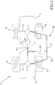
- a tractor 1 comprises a front frame 2 and a rear frame 3 rotatably associated in a fulcrum 4 ( figures 1 and 2 ).
- the front frame 2 supports a front engine 5 for driving front wheels 6, while the rear frame 3 supports a rear engine 7 for driving rear wheels 8.
- the tractor 1 further comprises a pump 9 and a bypass group 10 ( figures 2 to 5 ).
- the distance between the fulcrum 4 and a front axle 11 of the front wheels 6 is X 1
- the distance between the fulcrum 4 and a rear axle 12 of the rear wheels 8 is X 2 ( figure 1 ).
- X 1 is less than X 2 ; the difference between X 1 and X 2 preferably is less than 5%, preferably it is equal to 2%.
- X 1 could be greater than or equal to X 2 .
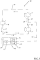
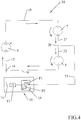
- the bypass group 10 comprises, in series on a same hydraulic line 15, a non-return valve 13 which allows the passage of fluid (oil) only in a first direction and a switchable valve 14 able to switch between a position P 1 in which fluid passage is allowed only in a second direction opposite to said first direction, and a position P 2 in which fluid passage is allowed both in the first and in the second direction.
- the hydraulic line 15 converges in a node 16 in which a hydraulic line 17 converging from pump 9 and a hydraulic line 18 connecting to the front engine 5, also converge.
- the pump 9 is connected to the rear engine 7 via a hydraulic line 19.
- the hydraulic line 15 connects the node 16 with a node 20 which hydraulically connects, via hydraulic lines 21, 22, also the rear engine 7 with the front engine 5, respectively.
- the front engine 5 and the rear engine 7 therefore are in hydraulic communication via the pump 9, the bypass group 10 and the hydraulic lines 21, 22 ( figures 2 to 5 ).
- the pump 9 may pump oil both towards the front engine 5 ( figure 3 ) and towards the rear engine 7 ( figure 4 ).
- the tractor 1 is moving in the configurations of the hydraulic circuit 30 in figures 3 and 4 .
- the oil puts into rotation the front engine 5 and then the rear engine 7 in series with each other.
- the hydraulic circuit 30 closes due to the hydraulic line 19 that bring the oil back to the pump 9.
- Oil does not flow through the bypass group 10 because the switchable valve 14 is in position P 1 .
- the operating oil flow may vary between 0 and 35 l/min (liters per minute), with maximum nominal flow rates between 25 and 35 1/min (liters per minute), preferably of 30 l/min.
- the pump 9 is idling in the configuration of figure 5 , i.e. the one in which the tractor is stationary.
- the front engine 5 and the rear engine 7 pump oil towards the node 20 because the rotation of the steering wheel induces the rotation about fulcrum 4 of the rear frame 3 with respect to the front frame 2: the force applied by the operator on the steering wheel induces the front engine 5 and the rear engine 7 to operate as pumps.
- the oil flow induced by the steering is very low, in the order of one l/min.
- the switchable valve 14 switches into position P 2 because the threshold value is greater than the flow rate flowing through the hydraulic line 15: the bypass group 10 then allows the flowing of the oil, thus allowing the steering.
- the bypass group 10 allows steering tractor 1 also when it is stationary, i.e. when the pump 9 is idling, with a simple variation of the hydraulic circuit 30.
- the bypass group 10 comprises commonly used valves 13, 14, does not make the tractor heavier and remains substantially neutral when the engines are put into rotation without modifying the performance of the engines themselves in any manner.
- the switchable valve 14 is flexible in use: the switching threshold value is easily settable according to usage needs.
- a tractor 1 advantageously may be made with the traditional hinged double frame scheme, thus ensuring the steering also when the tractor is stationary.
- Cutting means, spraying means, means for removing snow or ice, brushes for leaves, shredding means and more again, may alternatively be associated with the tractor.
- the tractor allows covering very large grounds with a significant flexibility of use.
Landscapes
- Engineering & Computer Science (AREA)
- Chemical & Material Sciences (AREA)
- Combustion & Propulsion (AREA)
- Transportation (AREA)
- Mechanical Engineering (AREA)
- Arrangement And Driving Of Transmission Devices (AREA)
- Guiding Agricultural Machines (AREA)
Description
- The present invention relates to a tractor with a bypass group for stationary steering.
- It is known to use tractors of limited sizes, associated alternatively with cutting means, spraying means, means for removing snow or ice, brushes for leaves, shredding means and more.
- The tractor allows covering very large areas with a significant flexibility of use.
- Four-wheel drive tractors formed by a front frame and a rear frame hinged to each other in a fulcrum, are commonly used.
- The rotation axis of the front frame with respect to the rear frame is at said fulcrum, at a distance X1 from the front axle of the front wheels, which is different from distance X2 of the rotation axis from the rear axle of the rear wheels.
- The front wheels are driven by a front engine supplied by a hydraulic pump which also supplies a rear engine which drives the rear wheels.
- Said front and rear engines are hydraulically supplied in series in both directions by said pump.
- The steering occurs due to a mechanical transmission (for example, a chain transmission that runs under the tractor) which connects the steering wheel to the rear frame, thus inducing the rotation thereof about the fulcrum.
- The pump idles when the tractor is stationary: the oil flow in the hydraulic circuit is substantially null.
- Disadvantageously, if steering is performed when the tractor is stationary, the engines operate as pump, generating a contrary oil flow therebetween: the steering is blocked at a given point. This occurs due to the above-described double frame construction solution.
- The prior art proposes technical solutions of electronic type for assisting with the steering: see e.g.
US-8909428 ,CN-205826206 andKR-10-1549303 B1 - However, none of said documents deals with the problem of the steering with the tractor stationary, in which there are four driving wheels with two frames hinged between the axles of the front and rear wheels, as described above.
- In particular, none of them looks for a hydraulic solution that does not complicate the electronics of the tractor.
- A hydraulic four-wheel driving articulated vehicle is known from
US 2005/178599 A1 - It is the object of the present invention to make a tractor with a hydraulic circuit that helps the steering when the tractor is stationary, in particular for a four-wheel drive tractor with two frames hinged between the axles of the front and rear wheels.
- It is a further object of the present invention that said hydraulic circuit is simple to make, in particular involving slight modifications to the hydraulic circuits currently used on double frame tractors.
- It is a still further object of the present invention that the use of said new hydraulic circuit does not result in a substantial modification of the control electronics of the hydraulic circuit itself, and of the tractor in general.
- According to the invention, these and further objects are achieved with a tractor comprising a front frame and a rear frame rotatably associated in a fulcrum, the front frame supports a front engine for driving front wheels, while the rear frame supports a rear engine for driving rear wheels, said tractor further comprises a pump in hydraulic communication with the front engine and the rear engine, and comprises a bypass group in hydraulic communication with the pump and with the front engine and the rear engine, the bypass group comprises, in series on a first hydraulic line of a hydraulic circuit, a non-return valve which allows the passage of fluid only in a first direction and a switchable valve able to switch between a first position in which fluid passage is allowed only in a second direction opposite to said first direction, and a second position in which fluid passage is allowed both in the first and in the second direction.
- Advantageously, the bypass group allows steering the tractor also when it is stationary, i.e. when the pump is idling, with a simple variation of the hydraulic circuit.
- The bypass group comprises commonly used valves, does not make the tractor heavier, and remains substantially neutral when the engines are put into rotation, without modifying the performance of the engines themselves in any manner.
- The switchable valve is flexible in use: the threshold switching value is easily settable according to usage needs.
- A tractor advantageously may be made with the traditional hinged double frame scheme, thus ensuring the steering also when the tractor is stationary.
- These and other features of the present invention will become more apparent from the following detailed description of a practical embodiment thereof, shown by way of non-limiting example in the accompanying drawings, in which:
-
figure 1 shows a side view of a tractor; -
figure 2 shows a diagrammatic top plan view of the tractor; -
figure 3 shows a hydraulic circuit diagram, in a first operating configuration; -
figure 4 shows the hydraulic circuit diagram, in a second operating configuration; -
figure 5 shows the hydraulic circuit diagram, in a third operating configuration. - A
tractor 1 comprises afront frame 2 and arear frame 3 rotatably associated in a fulcrum 4 (figures 1 and2 ). - The
front frame 2 supports afront engine 5 for drivingfront wheels 6, while therear frame 3 supports arear engine 7 for drivingrear wheels 8. - The
tractor 1 further comprises apump 9 and a bypass group 10 (figures 2 to 5 ). - The distance between the
fulcrum 4 and afront axle 11 of thefront wheels 6 is X1, while the distance between thefulcrum 4 and arear axle 12 of therear wheels 8 is X2 (figure 1 ). - In the present embodiment, X1 is less than X2; the difference between X1 and X2 preferably is less than 5%, preferably it is equal to 2%.
- Alternatively, X1 could be greater than or equal to X2.
- Experimental tests have shown that the steering problems occur especially when X1 differs from X2, the technical solution herein claimed being optimal for the above-mentioned differences between X1 and X2.
- In a
hydraulic circuit 30 of thetractor 1, thebypass group 10 comprises, in series on a samehydraulic line 15, anon-return valve 13 which allows the passage of fluid (oil) only in a first direction and aswitchable valve 14 able to switch between a position P1 in which fluid passage is allowed only in a second direction opposite to said first direction, and a position P2 in which fluid passage is allowed both in the first and in the second direction. - The
hydraulic line 15 converges in anode 16 in which ahydraulic line 17 converging frompump 9 and ahydraulic line 18 connecting to thefront engine 5, also converge. - The
pump 9 is connected to therear engine 7 via ahydraulic line 19. - The
hydraulic line 15 connects thenode 16 with anode 20 which hydraulically connects, viahydraulic lines rear engine 7 with thefront engine 5, respectively. - The
front engine 5 and therear engine 7 therefore are in hydraulic communication via thepump 9, thebypass group 10 and thehydraulic lines 21, 22 (figures 2 to 5 ). - Operatively, the
pump 9 may pump oil both towards the front engine 5 (figure 3 ) and towards the rear engine 7 (figure 4 ). - The
tractor 1 is moving in the configurations of thehydraulic circuit 30 infigures 3 and4 . - In
figure 3 , the oil flows through thehydraulic line 17 and then thehydraulic line 18, without crossing thebypass group 10 for the blocking activity of thenon-return valve 13. - The oil puts into rotation the
front engine 5 and then therear engine 7 in series with each other. - The
hydraulic circuit 30 closes due to thehydraulic line 19 that bring the oil back to thepump 9. - If the flowing direction of the oil is opposite (
figure 4 ), the oil reaches thefront engine 5 after operating therear engine 7. - Oil does not flow through the
bypass group 10 because theswitchable valve 14 is in position P1. - The operating oil flow may vary between 0 and 35 l/min (liters per minute), with maximum nominal flow rates between 25 and 35 1/min (liters per minute), preferably of 30 l/min.
- In the configuration of
figure 4 , oil does not flow through thebypass group 10 because theswitchable valve 14 has an action threshold value which is less than the maximum flow rate of the pump. Said action threshold is regulated between 2 and 12 l/min, preferably is 5 l/min. - The steering does not pose any problem in the configurations of
figures 3 and4 , i.e. with thetractor 1 moving, because theengines - The
pump 9 is idling in the configuration offigure 5 , i.e. the one in which the tractor is stationary. - If steering is started (the steering wheel is turned), the
front engine 5 and therear engine 7 pump oil towards thenode 20 because the rotation of the steering wheel induces the rotation aboutfulcrum 4 of therear frame 3 with respect to the front frame 2: the force applied by the operator on the steering wheel induces thefront engine 5 and therear engine 7 to operate as pumps. - The oil flow induced by the steering is very low, in the order of one l/min.
- Accordingly, the
switchable valve 14 switches into position P2 because the threshold value is greater than the flow rate flowing through the hydraulic line 15: thebypass group 10 then allows the flowing of the oil, thus allowing the steering. - Without the
bypass group 10, the opposite oil flow between the twoengines engines - Advantageously, the
bypass group 10 allowssteering tractor 1 also when it is stationary, i.e. when thepump 9 is idling, with a simple variation of thehydraulic circuit 30. - The
bypass group 10 comprises commonly usedvalves - The
switchable valve 14 is flexible in use: the switching threshold value is easily settable according to usage needs. - A
tractor 1 advantageously may be made with the traditional hinged double frame scheme, thus ensuring the steering also when the tractor is stationary. - Cutting means, spraying means, means for removing snow or ice, brushes for leaves, shredding means and more again, may alternatively be associated with the tractor.
- The tractor allows covering very large grounds with a significant flexibility of use.
Claims (6)
- Tractor (1) comprising a front frame (2) and a rear frame (3) rotatably associated in a fulcrum (4), the front frame (2) supports a front engine (5) for driving front wheels (6), while the rear frame (3) supports a rear engine (7) for driving rear wheels (8),
said tractor (1) further comprises a pump (9) in hydraulic communication with the front engine (5) and the rear engine (7),
and comprises a bypass group (10) in hydraulic communication with the pump (9) and with the front engine (5) and the rear engine (7),
the bypass group (10) comprises, in series on a first hydraulic line (15) of a hydraulic circuit (30), a non-return valve (13) which allows the passage of fluid only in a first direction, and a switchable valve (14) able to switch between a first position (P1) in which fluid passage is allowed only in a second direction opposite to said first direction, and a second position (P2) in which fluid passage is allowed both in the first and in the second direction. - Tractor (1) according to claim 1, characterized in that in said hydraulic circuit (30), the first hydraulic line (15) converges into a first node (16) in which also converge a second hydraulic line (17) converging from the pump (9), and a third hydraulic line (18) that connects to the front engine (5),
the pump (9) is connected to the rear engine (7) via a fourth hydraulic line (19),
the first hydraulic line (15) connects the first node (16) with a second node (20) which hydraulically connects, via a fifth (21) and a sixth hydraulic line (22), also the rear engine (7) with the front engine (5) respectively. - Tractor (1) according to claim 1 or 2, characterized in that the switchable valve (14) is able to switch on reaching an oil flow threshold value.
- Tractor (1) according to claim 3, characterized in that the threshold value is lower than the maximum nominal oil flow rate.
- Tractor (1) according to claim 4, characterized in that the threshold value is between 2 and 12 l/min, preferably it is equal to 5 l/min.
- Tractor (1) according to any one of the previous claims, characterized in that said fulcrum (4) is at a first distance (X1) from a front axle (11) of the front wheels (6), and at a second distance (X2) from a rear axle (12) of the rear wheels (8), the difference between the first distance (X1) and the second distance (X2) is less than 5%, preferably equal to 2%.
Applications Claiming Priority (1)
| Application Number | Priority Date | Filing Date | Title |
|---|---|---|---|
| IT201800006376 | 2018-06-15 |
Publications (2)
| Publication Number | Publication Date |
|---|---|
| EP3581421A1 EP3581421A1 (en) | 2019-12-18 |
| EP3581421B1 true EP3581421B1 (en) | 2021-03-03 |
Family
ID=63579660
Family Applications (1)
| Application Number | Title | Priority Date | Filing Date |
|---|---|---|---|
| EP19178189.7A Active EP3581421B1 (en) | 2018-06-15 | 2019-06-04 | Tractor with bypass group for stationary steering |
Country Status (1)
| Country | Link |
|---|---|
| EP (1) | EP3581421B1 (en) |
Families Citing this family (1)
| Publication number | Priority date | Publication date | Assignee | Title |
|---|---|---|---|---|
| CN112829571A (en) * | 2021-03-11 | 2021-05-25 | 河南玉柴机械设备有限公司 | A powertrain for a four-wheel drive tractor |
Family Cites Families (6)
| Publication number | Priority date | Publication date | Assignee | Title |
|---|---|---|---|---|
| US4947956A (en) * | 1987-10-13 | 1990-08-14 | Clark Equipment Company | Hydrostatic transmissions system for an articulated vehicle |
| US6035909A (en) * | 1998-12-08 | 2000-03-14 | Caterpillar Inc. | Hydraulic drive for a feller-buncher |
| JP2005153703A (en) * | 2003-11-26 | 2005-06-16 | Kanzaki Kokyukoki Mfg Co Ltd | Hydraulic driving type four-wheel drive working vehicle being fuselage bending type |
| US8909428B1 (en) | 2013-01-09 | 2014-12-09 | Google Inc. | Detecting driver grip on steering wheel |
| KR101549303B1 (en) | 2013-10-15 | 2015-09-01 | 대성전기공업 주식회사 | Torque sensor output circuit in electric power steering apparatus |
| CN205826206U (en) | 2016-05-31 | 2016-12-21 | 耐世特汽车系统(苏州)有限公司 | A kind of moment of torsion automatic check device for electronic power steering apparatus test machine |
-
2019
- 2019-06-04 EP EP19178189.7A patent/EP3581421B1/en active Active
Non-Patent Citations (1)
| Title |
|---|
| None * |
Also Published As
| Publication number | Publication date |
|---|---|
| EP3581421A1 (en) | 2019-12-18 |
Similar Documents
| Publication | Publication Date | Title |
|---|---|---|
| US5915496A (en) | Parallel-series four-wheel-drive hydraulic circuit for a riding lawn mower | |
| WO2015024399A1 (en) | Turning system and heavy-load wheeled vehicle having independent suspension | |
| EP3581421B1 (en) | Tractor with bypass group for stationary steering | |
| US20230077263A1 (en) | Traction control for steering articulated power machine | |
| CN104369665B (en) | Hydraulic power bull-dozer and speed change steering hydraulic system thereof | |
| US2818125A (en) | Hydraulic driving and steering transmission for vehicles | |
| JP4886556B2 (en) | All-wheel hydraulically driven lawn mower | |
| WO2014029555A1 (en) | Steering system for a trailing axle of a vehicle | |
| US7770685B2 (en) | Propulsion system for a work vehicle having a single drive pump and differential capability | |
| CN212034899U (en) | Walking device of sugarcane harvester | |
| JPS5842393B2 (en) | self-propelled car | |
| US6854539B2 (en) | Vehicle steering system | |
| JPH035170Y2 (en) | ||
| CN108980232A (en) | A kind of PTO output protection system and tractor | |
| US6702055B1 (en) | Hydrostatic travelling mechanism | |
| JPS6117442B2 (en) | ||
| JPS6242825Y2 (en) | ||
| JPH0248292Y2 (en) | ||
| JP3815990B2 (en) | Work machine travel operation circuit | |
| CN104170585A (en) | Traveling hydraulic control system for cane harvester | |
| EP2407692B1 (en) | Hydraulic traction drive for a lawnmower | |
| JPH035504Y2 (en) | ||
| DE202005018429U1 (en) | Cross country wheeled tractor, with oil motors at the driven wheels, has an intermediate setting at the control valve between forward and reverse drives where oil flow is blocked to and from the motors | |
| JPH0248291Y2 (en) | ||
| JP2001150969A (en) | Control working vehicle |
Legal Events
| Date | Code | Title | Description |
|---|---|---|---|
| PUAI | Public reference made under article 153(3) epc to a published international application that has entered the european phase |
Free format text: ORIGINAL CODE: 0009012 |
|
| STAA | Information on the status of an ep patent application or granted ep patent |
Free format text: STATUS: THE APPLICATION HAS BEEN PUBLISHED |
|
| AK | Designated contracting states |
Kind code of ref document: A1 Designated state(s): AL AT BE BG CH CY CZ DE DK EE ES FI FR GB GR HR HU IE IS IT LI LT LU LV MC MK MT NL NO PL PT RO RS SE SI SK SM TR |
|
| AX | Request for extension of the european patent |
Extension state: BA ME |
|
| STAA | Information on the status of an ep patent application or granted ep patent |
Free format text: STATUS: REQUEST FOR EXAMINATION WAS MADE |
|
| 17P | Request for examination filed |
Effective date: 20200317 |
|
| RBV | Designated contracting states (corrected) |
Designated state(s): AL AT BE BG CH CY CZ DE DK EE ES FI FR GB GR HR HU IE IS IT LI LT LU LV MC MK MT NL NO PL PT RO RS SE SI SK SM TR |
|
| RIC1 | Information provided on ipc code assigned before grant |
Ipc: B60K 17/356 20060101ALI20200804BHEP Ipc: B60K 17/10 20060101AFI20200804BHEP |
|
| GRAP | Despatch of communication of intention to grant a patent |
Free format text: ORIGINAL CODE: EPIDOSNIGR1 |
|
| STAA | Information on the status of an ep patent application or granted ep patent |
Free format text: STATUS: GRANT OF PATENT IS INTENDED |
|
| INTG | Intention to grant announced |
Effective date: 20201001 |
|
| GRAS | Grant fee paid |
Free format text: ORIGINAL CODE: EPIDOSNIGR3 |
|
| GRAA | (expected) grant |
Free format text: ORIGINAL CODE: 0009210 |
|
| STAA | Information on the status of an ep patent application or granted ep patent |
Free format text: STATUS: THE PATENT HAS BEEN GRANTED |
|
| AK | Designated contracting states |
Kind code of ref document: B1 Designated state(s): AL AT BE BG CH CY CZ DE DK EE ES FI FR GB GR HR HU IE IS IT LI LT LU LV MC MK MT NL NO PL PT RO RS SE SI SK SM TR |
|
| REG | Reference to a national code |
Ref country code: GB Ref legal event code: FG4D |
|
| REG | Reference to a national code |
Ref country code: CH Ref legal event code: EP Ref country code: AT Ref legal event code: REF Ref document number: 1366834 Country of ref document: AT Kind code of ref document: T Effective date: 20210315 |
|
| REG | Reference to a national code |
Ref country code: DE Ref legal event code: R096 Ref document number: 602019002895 Country of ref document: DE |
|
| REG | Reference to a national code |
Ref country code: IE Ref legal event code: FG4D |
|
| REG | Reference to a national code |
Ref country code: SE Ref legal event code: TRGR |
|
| REG | Reference to a national code |
Ref country code: LT Ref legal event code: MG9D |
|
| PG25 | Lapsed in a contracting state [announced via postgrant information from national office to epo] |
Ref country code: NO Free format text: LAPSE BECAUSE OF FAILURE TO SUBMIT A TRANSLATION OF THE DESCRIPTION OR TO PAY THE FEE WITHIN THE PRESCRIBED TIME-LIMIT Effective date: 20210603 Ref country code: LT Free format text: LAPSE BECAUSE OF FAILURE TO SUBMIT A TRANSLATION OF THE DESCRIPTION OR TO PAY THE FEE WITHIN THE PRESCRIBED TIME-LIMIT Effective date: 20210303 Ref country code: HR Free format text: LAPSE BECAUSE OF FAILURE TO SUBMIT A TRANSLATION OF THE DESCRIPTION OR TO PAY THE FEE WITHIN THE PRESCRIBED TIME-LIMIT Effective date: 20210303 Ref country code: BG Free format text: LAPSE BECAUSE OF FAILURE TO SUBMIT A TRANSLATION OF THE DESCRIPTION OR TO PAY THE FEE WITHIN THE PRESCRIBED TIME-LIMIT Effective date: 20210603 Ref country code: GR Free format text: LAPSE BECAUSE OF FAILURE TO SUBMIT A TRANSLATION OF THE DESCRIPTION OR TO PAY THE FEE WITHIN THE PRESCRIBED TIME-LIMIT Effective date: 20210604 Ref country code: FI Free format text: LAPSE BECAUSE OF FAILURE TO SUBMIT A TRANSLATION OF THE DESCRIPTION OR TO PAY THE FEE WITHIN THE PRESCRIBED TIME-LIMIT Effective date: 20210303 |
|
| REG | Reference to a national code |
Ref country code: NL Ref legal event code: MP Effective date: 20210303 |
|
| REG | Reference to a national code |
Ref country code: AT Ref legal event code: MK05 Ref document number: 1366834 Country of ref document: AT Kind code of ref document: T Effective date: 20210303 |
|
| PG25 | Lapsed in a contracting state [announced via postgrant information from national office to epo] |
Ref country code: RS Free format text: LAPSE BECAUSE OF FAILURE TO SUBMIT A TRANSLATION OF THE DESCRIPTION OR TO PAY THE FEE WITHIN THE PRESCRIBED TIME-LIMIT Effective date: 20210303 Ref country code: PL Free format text: LAPSE BECAUSE OF FAILURE TO SUBMIT A TRANSLATION OF THE DESCRIPTION OR TO PAY THE FEE WITHIN THE PRESCRIBED TIME-LIMIT Effective date: 20210303 Ref country code: LV Free format text: LAPSE BECAUSE OF FAILURE TO SUBMIT A TRANSLATION OF THE DESCRIPTION OR TO PAY THE FEE WITHIN THE PRESCRIBED TIME-LIMIT Effective date: 20210303 |
|
| PG25 | Lapsed in a contracting state [announced via postgrant information from national office to epo] |
Ref country code: NL Free format text: LAPSE BECAUSE OF FAILURE TO SUBMIT A TRANSLATION OF THE DESCRIPTION OR TO PAY THE FEE WITHIN THE PRESCRIBED TIME-LIMIT Effective date: 20210303 |
|
| PG25 | Lapsed in a contracting state [announced via postgrant information from national office to epo] |
Ref country code: EE Free format text: LAPSE BECAUSE OF FAILURE TO SUBMIT A TRANSLATION OF THE DESCRIPTION OR TO PAY THE FEE WITHIN THE PRESCRIBED TIME-LIMIT Effective date: 20210303 Ref country code: CZ Free format text: LAPSE BECAUSE OF FAILURE TO SUBMIT A TRANSLATION OF THE DESCRIPTION OR TO PAY THE FEE WITHIN THE PRESCRIBED TIME-LIMIT Effective date: 20210303 Ref country code: AT Free format text: LAPSE BECAUSE OF FAILURE TO SUBMIT A TRANSLATION OF THE DESCRIPTION OR TO PAY THE FEE WITHIN THE PRESCRIBED TIME-LIMIT Effective date: 20210303 Ref country code: SM Free format text: LAPSE BECAUSE OF FAILURE TO SUBMIT A TRANSLATION OF THE DESCRIPTION OR TO PAY THE FEE WITHIN THE PRESCRIBED TIME-LIMIT Effective date: 20210303 |
|
| PG25 | Lapsed in a contracting state [announced via postgrant information from national office to epo] |
Ref country code: IS Free format text: LAPSE BECAUSE OF FAILURE TO SUBMIT A TRANSLATION OF THE DESCRIPTION OR TO PAY THE FEE WITHIN THE PRESCRIBED TIME-LIMIT Effective date: 20210703 Ref country code: SK Free format text: LAPSE BECAUSE OF FAILURE TO SUBMIT A TRANSLATION OF THE DESCRIPTION OR TO PAY THE FEE WITHIN THE PRESCRIBED TIME-LIMIT Effective date: 20210303 Ref country code: PT Free format text: LAPSE BECAUSE OF FAILURE TO SUBMIT A TRANSLATION OF THE DESCRIPTION OR TO PAY THE FEE WITHIN THE PRESCRIBED TIME-LIMIT Effective date: 20210705 Ref country code: RO Free format text: LAPSE BECAUSE OF FAILURE TO SUBMIT A TRANSLATION OF THE DESCRIPTION OR TO PAY THE FEE WITHIN THE PRESCRIBED TIME-LIMIT Effective date: 20210303 |
|
| REG | Reference to a national code |
Ref country code: DE Ref legal event code: R097 Ref document number: 602019002895 Country of ref document: DE |
|
| PLBE | No opposition filed within time limit |
Free format text: ORIGINAL CODE: 0009261 |
|
| STAA | Information on the status of an ep patent application or granted ep patent |
Free format text: STATUS: NO OPPOSITION FILED WITHIN TIME LIMIT |
|
| PG25 | Lapsed in a contracting state [announced via postgrant information from national office to epo] |
Ref country code: MC Free format text: LAPSE BECAUSE OF FAILURE TO SUBMIT A TRANSLATION OF THE DESCRIPTION OR TO PAY THE FEE WITHIN THE PRESCRIBED TIME-LIMIT Effective date: 20210303 Ref country code: AL Free format text: LAPSE BECAUSE OF FAILURE TO SUBMIT A TRANSLATION OF THE DESCRIPTION OR TO PAY THE FEE WITHIN THE PRESCRIBED TIME-LIMIT Effective date: 20210303 Ref country code: DK Free format text: LAPSE BECAUSE OF FAILURE TO SUBMIT A TRANSLATION OF THE DESCRIPTION OR TO PAY THE FEE WITHIN THE PRESCRIBED TIME-LIMIT Effective date: 20210303 Ref country code: ES Free format text: LAPSE BECAUSE OF FAILURE TO SUBMIT A TRANSLATION OF THE DESCRIPTION OR TO PAY THE FEE WITHIN THE PRESCRIBED TIME-LIMIT Effective date: 20210303 |
|
| 26N | No opposition filed |
Effective date: 20211206 |
|
| PG25 | Lapsed in a contracting state [announced via postgrant information from national office to epo] |
Ref country code: SI Free format text: LAPSE BECAUSE OF FAILURE TO SUBMIT A TRANSLATION OF THE DESCRIPTION OR TO PAY THE FEE WITHIN THE PRESCRIBED TIME-LIMIT Effective date: 20210303 |
|
| REG | Reference to a national code |
Ref country code: BE Ref legal event code: MM Effective date: 20210630 |
|
| PG25 | Lapsed in a contracting state [announced via postgrant information from national office to epo] |
Ref country code: LU Free format text: LAPSE BECAUSE OF NON-PAYMENT OF DUE FEES Effective date: 20210604 |
|
| PG25 | Lapsed in a contracting state [announced via postgrant information from national office to epo] |
Ref country code: IE Free format text: LAPSE BECAUSE OF NON-PAYMENT OF DUE FEES Effective date: 20210604 |
|
| PG25 | Lapsed in a contracting state [announced via postgrant information from national office to epo] |
Ref country code: IS Free format text: LAPSE BECAUSE OF FAILURE TO SUBMIT A TRANSLATION OF THE DESCRIPTION OR TO PAY THE FEE WITHIN THE PRESCRIBED TIME-LIMIT Effective date: 20210703 |
|
| PG25 | Lapsed in a contracting state [announced via postgrant information from national office to epo] |
Ref country code: BE Free format text: LAPSE BECAUSE OF NON-PAYMENT OF DUE FEES Effective date: 20210630 |
|
| REG | Reference to a national code |
Ref country code: CH Ref legal event code: PL |
|
| PG25 | Lapsed in a contracting state [announced via postgrant information from national office to epo] |
Ref country code: LI Free format text: LAPSE BECAUSE OF NON-PAYMENT OF DUE FEES Effective date: 20220630 Ref country code: CH Free format text: LAPSE BECAUSE OF NON-PAYMENT OF DUE FEES Effective date: 20220630 |
|
| P01 | Opt-out of the competence of the unified patent court (upc) registered |
Effective date: 20230421 |
|
| PG25 | Lapsed in a contracting state [announced via postgrant information from national office to epo] |
Ref country code: CY Free format text: LAPSE BECAUSE OF FAILURE TO SUBMIT A TRANSLATION OF THE DESCRIPTION OR TO PAY THE FEE WITHIN THE PRESCRIBED TIME-LIMIT Effective date: 20210303 |
|
| PG25 | Lapsed in a contracting state [announced via postgrant information from national office to epo] |
Ref country code: HU Free format text: LAPSE BECAUSE OF FAILURE TO SUBMIT A TRANSLATION OF THE DESCRIPTION OR TO PAY THE FEE WITHIN THE PRESCRIBED TIME-LIMIT; INVALID AB INITIO Effective date: 20190604 |
|
| PG25 | Lapsed in a contracting state [announced via postgrant information from national office to epo] |
Ref country code: MK Free format text: LAPSE BECAUSE OF FAILURE TO SUBMIT A TRANSLATION OF THE DESCRIPTION OR TO PAY THE FEE WITHIN THE PRESCRIBED TIME-LIMIT Effective date: 20210303 |
|
| PG25 | Lapsed in a contracting state [announced via postgrant information from national office to epo] |
Ref country code: MT Free format text: LAPSE BECAUSE OF FAILURE TO SUBMIT A TRANSLATION OF THE DESCRIPTION OR TO PAY THE FEE WITHIN THE PRESCRIBED TIME-LIMIT Effective date: 20210303 |
|
| PGFP | Annual fee paid to national office [announced via postgrant information from national office to epo] |
Ref country code: GB Payment date: 20250523 Year of fee payment: 7 |
|
| PGFP | Annual fee paid to national office [announced via postgrant information from national office to epo] |
Ref country code: IT Payment date: 20250522 Year of fee payment: 7 |
|
| PGFP | Annual fee paid to national office [announced via postgrant information from national office to epo] |
Ref country code: FR Payment date: 20250626 Year of fee payment: 7 |
|
| PGFP | Annual fee paid to national office [announced via postgrant information from national office to epo] |
Ref country code: SE Payment date: 20250626 Year of fee payment: 7 |
|
| PGFP | Annual fee paid to national office [announced via postgrant information from national office to epo] |
Ref country code: DE Payment date: 20250725 Year of fee payment: 7 |
|
| PG25 | Lapsed in a contracting state [announced via postgrant information from national office to epo] |
Ref country code: TR Free format text: LAPSE BECAUSE OF FAILURE TO SUBMIT A TRANSLATION OF THE DESCRIPTION OR TO PAY THE FEE WITHIN THE PRESCRIBED TIME-LIMIT Effective date: 20210303 |