EP3581416A1 - Dispositif de transmission, notamment pour véhicule électrique - Google Patents
Dispositif de transmission, notamment pour véhicule électrique Download PDFInfo
- Publication number
- EP3581416A1 EP3581416A1 EP19180367.5A EP19180367A EP3581416A1 EP 3581416 A1 EP3581416 A1 EP 3581416A1 EP 19180367 A EP19180367 A EP 19180367A EP 3581416 A1 EP3581416 A1 EP 3581416A1
- Authority
- EP
- European Patent Office
- Prior art keywords
- shaft
- electric machine
- gear
- transmission device
- tertiary
- Prior art date
- Legal status (The legal status is an assumption and is not a legal conclusion. Google has not performed a legal analysis and makes no representation as to the accuracy of the status listed.)
- Granted
Links
Images


Classifications
-
- B—PERFORMING OPERATIONS; TRANSPORTING
- B60—VEHICLES IN GENERAL
- B60K—ARRANGEMENT OR MOUNTING OF PROPULSION UNITS OR OF TRANSMISSIONS IN VEHICLES; ARRANGEMENT OR MOUNTING OF PLURAL DIVERSE PRIME-MOVERS IN VEHICLES; AUXILIARY DRIVES FOR VEHICLES; INSTRUMENTATION OR DASHBOARDS FOR VEHICLES; ARRANGEMENTS IN CONNECTION WITH COOLING, AIR INTAKE, GAS EXHAUST OR FUEL SUPPLY OF PROPULSION UNITS IN VEHICLES
- B60K1/00—Arrangement or mounting of electrical propulsion units
- B60K1/02—Arrangement or mounting of electrical propulsion units comprising more than one electric motor
-
- B—PERFORMING OPERATIONS; TRANSPORTING
- B60—VEHICLES IN GENERAL
- B60K—ARRANGEMENT OR MOUNTING OF PROPULSION UNITS OR OF TRANSMISSIONS IN VEHICLES; ARRANGEMENT OR MOUNTING OF PLURAL DIVERSE PRIME-MOVERS IN VEHICLES; AUXILIARY DRIVES FOR VEHICLES; INSTRUMENTATION OR DASHBOARDS FOR VEHICLES; ARRANGEMENTS IN CONNECTION WITH COOLING, AIR INTAKE, GAS EXHAUST OR FUEL SUPPLY OF PROPULSION UNITS IN VEHICLES
- B60K17/00—Arrangement or mounting of transmissions in vehicles
- B60K17/04—Arrangement or mounting of transmissions in vehicles characterised by arrangement, location or kind of gearing
- B60K17/06—Arrangement or mounting of transmissions in vehicles characterised by arrangement, location or kind of gearing of change-speed gearing
- B60K17/08—Arrangement or mounting of transmissions in vehicles characterised by arrangement, location or kind of gearing of change-speed gearing of mechanical type
-
- F—MECHANICAL ENGINEERING; LIGHTING; HEATING; WEAPONS; BLASTING
- F16—ENGINEERING ELEMENTS AND UNITS; GENERAL MEASURES FOR PRODUCING AND MAINTAINING EFFECTIVE FUNCTIONING OF MACHINES OR INSTALLATIONS; THERMAL INSULATION IN GENERAL
- F16H—GEARING
- F16H2200/00—Transmissions for multiple ratios
- F16H2200/0021—Transmissions for multiple ratios specially adapted for electric vehicles
-
- F—MECHANICAL ENGINEERING; LIGHTING; HEATING; WEAPONS; BLASTING
- F16—ENGINEERING ELEMENTS AND UNITS; GENERAL MEASURES FOR PRODUCING AND MAINTAINING EFFECTIVE FUNCTIONING OF MACHINES OR INSTALLATIONS; THERMAL INSULATION IN GENERAL
- F16H—GEARING
- F16H2200/00—Transmissions for multiple ratios
- F16H2200/003—Transmissions for multiple ratios characterised by the number of forward speeds
- F16H2200/0034—Transmissions for multiple ratios characterised by the number of forward speeds the gear ratios comprising two forward speeds
-
- F—MECHANICAL ENGINEERING; LIGHTING; HEATING; WEAPONS; BLASTING
- F16—ENGINEERING ELEMENTS AND UNITS; GENERAL MEASURES FOR PRODUCING AND MAINTAINING EFFECTIVE FUNCTIONING OF MACHINES OR INSTALLATIONS; THERMAL INSULATION IN GENERAL
- F16H—GEARING
- F16H3/00—Toothed gearings for conveying rotary motion with variable gear ratio or for reversing rotary motion
- F16H3/02—Toothed gearings for conveying rotary motion with variable gear ratio or for reversing rotary motion without gears having orbital motion
- F16H3/08—Toothed gearings for conveying rotary motion with variable gear ratio or for reversing rotary motion without gears having orbital motion exclusively or essentially with continuously meshing gears, that can be disengaged from their shafts
- F16H3/087—Toothed gearings for conveying rotary motion with variable gear ratio or for reversing rotary motion without gears having orbital motion exclusively or essentially with continuously meshing gears, that can be disengaged from their shafts characterised by the disposition of the gears
- F16H3/089—Toothed gearings for conveying rotary motion with variable gear ratio or for reversing rotary motion without gears having orbital motion exclusively or essentially with continuously meshing gears, that can be disengaged from their shafts characterised by the disposition of the gears all of the meshing gears being supported by a pair of parallel shafts, one being the input shaft and the other the output shaft, there being no countershaft involved
Definitions
- the present invention relates to the field of transmissions with at least two transmission ratios intended for use on electric motor vehicles.
- electric motor vehicle means all vehicles which use an electric machine as the main motor, the electric machine being the only driving machine (purely electric vehicles) or associated with an internal combustion engine (hybrid vehicles ).
- the transmissions with more than one report are used to equip electric vehicles and allow an operation of the electric machine at its optimal speed of rotation, i.e. at the speed of rotation corresponding to the maximum efficiency of the electric machine.
- This advantage applies both to a motor operating mode, in which the electric machine operates as a motor to generate the power necessary for the movement of the vehicle, and to a generator operating mode, in which the electric machine operates in both generator to convert the kinetic energy of the vehicle into electrical energy.
- each electric machine can in particular be one or more of the following characteristics: the supply voltage, the nominal current, the nominal power, the number of phases, the number of poles, the ratio of the rotation speed on supply voltage, nominal speed, nominal torque, rotor inertia, maximum current, maximum speed, maximum torque, efficiency, type of permanent magnet used, dimensions (diameter, length, width), mass.
- the transmission ratio is the ratio between the input rotation speed, that is to say the rotation speed of the rotor of the electric machine concerned in the case of the invention, and the rotation speed at the output of the transmission device.
- the use of two electric machines having different technical characteristics makes it possible to use a first electric machine ensuring for example the propulsion of the vehicle in the majority of operating cases, and to use the second electric machine in addition, if necessary increased torque, for example during an acceleration phase and / or to compensate for a torque breakdown when changing gear ratio on the first electric machine.
- the second electric machine may have a lower cost than the first electric machine and / or degraded technical characteristics by comparison with the technical characteristics of the first electric machine.
- the primary shaft and the tertiary shaft may be able to be connected by means of a first gear corresponding to a first transmission ratio or by means of a second gear corresponding to a second transmission ratio, coupling means making it possible to select said transmission ratio by activating or deactivating one or the other of said first and second gears.
- the simultaneous activation of the first gear and the second gear by the coupling means makes it possible to block the transmission device, in particular the tertiary shaft.
- the first gear and the second gear each comprise a idler gear carried by the primary shaft or the secondary shaft, each idler gear cooperating with a coupling means, such as a synchronizer, capable of securing it in rotation with the shaft primary or secondary who wears it.
- a coupling means such as a synchronizer
- the first and second transmission ratios can be different transmission ratios.
- the secondary shaft and the tertiary shaft may be able to be connected by means of a third gear corresponding to a third transmission ratio.
- the third transmission ratio may be different from the first and second transmission ratios.
- the third transmission ratio can be equal to one of the first and second transmission ratios.
- the first transmission ratio can be between 26 and 10.
- the second transmission ratio can be between 12 and 5.
- the third transmission ratio can be between 19 and 8.
- the transmission device may include coupling means able to activate or deactivate the third gear.
- the coupling means may include a controlled actuator.
- the first electric machine and the second electric machine can be located on either side of the gears.
- the first electric machine and the second electric machine can be located on the same side with respect to the gears, so as to reduce the bulk in the direction parallel to the primary axis and to the secondary axis.
- the first gear may comprise a first driving pinion disposed on the primary shaft and a first driven pinion disposed on the tertiary shaft, the first driving pinion, respectively the first driven pinion, being mounted idly on the primary shaft, respectively on the 'tertiary shaft, and being adapted to be coupled in rotation to the primary shaft, respectively to the tertiary shaft, by the corresponding coupling means.
- the first driven pinion can be integral and permanently connected to the tertiary shaft, respectively to the primary shaft.
- the second gear may comprise a second driving pinion arranged on the primary shaft and a second driven pinion arranged on the tertiary shaft, the second driving pinion, respectively the second driven pinion, being mounted idly on the primary shaft, respectively on the 'tertiary shaft, and being adapted to be coupled in rotation to the primary shaft, respectively to the tertiary shaft, by the corresponding coupling means.
- the second driven pinion can be integral and permanently connected to the tertiary shaft, respectively to the primary shaft.
- the third gear may comprise a third driving pinion arranged on the secondary shaft and a third driven pinion arranged on the tertiary shaft, the third driving pinion, respectively the third driven pinion, being mounted idly on the secondary shaft, respectively on the 'tertiary shaft, and being adapted to be coupled in rotation to the secondary shaft, respectively to the tertiary shaft, by the corresponding coupling means.
- the third driven pinion can be integral and permanently connected to the tertiary shaft, respectively to the secondary shaft.
- the second driven pinion and the third driven pinion can be formed by the same pinion, so as to reduce the complexity and the cost of the transmission device.
- the primary shaft, the secondary shaft and / or the tertiary shaft may include a shaft locking device.
- Such a locking device can be activated so as to block the corresponding shaft and prevent its rotation in the event of the vehicle being stopped or parked, for example.
- the coupling means may include at least one dog clutch or at least one synchronizer, capable of activating the gear concerned.
- the gear can be activated when the speed of rotation of the shaft concerned reaches a set speed.
- the coupling means may also include a friction clutch, for example a wet multi-plate clutch.
- a support bearing can be located at each end of the primary shaft, the secondary shaft and / or the tertiary shaft.
- a differential can be connected to the tertiary shaft by means of a differential gear, said differential being able to be connected to the wheels of the vehicle.
- the differential allows the drive wheels of the vehicle to turn at different speeds when passing a curve or a turn.
- the wheels located outside the turn can then turn faster than those located inside the turn.
- the first electric machine may have lower technical characteristics than the second electric machine.
- the technical characteristics may relate to the nominal power of the first electric machine and the nominal power of the second electric machine.
- the technical characteristics may relate to the nominal torque of the first electric machine and the nominal torque of the second electric machine.
- gear ratios can be associated with the first electric machine.
- the second electric machine can then be able to compensate for a break in torque when changing gear ratio on the first electric machine.
- transmission T acts as a reducer between the electrical machines M1, M2 and the wheels R1, R2 of the vehicle, that is to say, it aims to modify the speed and / or torque ratio between the shaft output of the electric machine M1, M2 concerned and the wheels R1, R2 of the vehicle.
- Each electric machine M1, M2 can for example be a synchronous electric machine with permanent magnets operating at low voltage, in particular a voltage between 30 and 60 Volts, for example of the order of 48 Volts for at least one of the electrical machines M1, M2.
- the first electric machine M1 has different technical characteristics from the second electric machine M2.
- each electric machine can in particular be one or more of the following characteristics: the supply voltage, the nominal current, the nominal power, the number of phases, the number of poles, the ratio of the rotation speed on supply voltage, nominal speed, nominal torque, rotor inertia, maximum current, maximum speed, maximum torque, efficiency, type of permanent magnet used, dimensions , the mass.
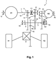
- the transmission device T of the figure 1 comprises a primary shaft 1 which is formed by the output shaft of the first electric machine M1.
- the primary shaft 1 can be coupled to the output shaft of the first electric machine M1.
- This coupling is then homokinetic and can be any type of mechanical coupling between two shafts, such as for example a coupling with splines.
- the transmission device T also comprises a secondary shaft 2 which is formed by the output shaft of the second electrical machine M2.
- the secondary shaft 2 can be coupled to the output shaft of the second electric machine M2.
- This coupling is then homokinetic and can be any type of mechanical coupling between two shafts, such as for example a coupling with splines.
- the transmission device T also comprises a tertiary shaft 3.
- the tertiary shaft 3 is able to be connected to a differential D itself connected to the wheels R1, R2 of the vehicle.
- a first gear 10 corresponding to a first transmission ratio comprises a first driving pinion 11 arranged on the primary shaft 1 and a first driven pinion 12 arranged on the tertiary shaft 3.
- the first driving pinion 11 and the first driven pinion 12 mesh permanently.
- a second gear 20 corresponding to a second transmission ratio comprises a second driving pinion 21 arranged on the primary shaft 1 and a second driven pinion 22 arranged on the tertiary shaft 3.
- the second driving pinion 21 and the second driven pinion 22 mesh permanently.
- the first driving pinion 11 and the second driving pinion 21 are idly mounted on the primary shaft 1, by means of needle bearings, and can thus rotate relative to the primary shaft 1.
- the first driven pinion 12 and the second driven pinion 22 are integral with the tertiary shaft 3.
- the reduction ratio between the first driving pinion 11 and the first driven pinion 12 can for example be between 5 and 2.
- the reduction ratio between the second driving pinion 21 and the second driven pinion 22 can for example be between 3.5 and 1.
- a third gear 30 corresponding to a third transmission ratio comprises a third driving pinion 31 arranged on the secondary shaft 2 and a second driven pinion 32 arranged on the tertiary shaft 3.
- the second driving pinion 31 and the second driven pinion 32 mesh permanently.
- the third driving pinion 31 is integral with the secondary shaft 2.
- the third driven pinion 32 is mounted idly on the tertiary shaft 3, by means of needle bearings, and can thus rotate relative to the tertiary shaft 3 .
- the reduction ratio between the third driving pinion 31 and the third driven pinion 32 can for example be between 5 and 1.5.
- a fourth gear corresponding to a gear 40 of differential D comprises a fourth driving pinion 41 disposed on the tertiary shaft 3 and a fourth driven pinion 42 corresponding to the input of the differential D.
- the fourth driving pinion 41 is fixedly mounted on the tertiary tree.
- the fourth driving pinion 41 and the fourth driven pinion 42 mesh constantly.
- the reduction ratio between the fourth driving pinion 41 and the fourth driven pinion 42 can for example be between 5 and 2.5.
- the four gears 10, 20, 30, 40 are oriented in parallel.
- the three shafts 1, 2, 3 are oriented in parallel.
- the different pinions 11, 12, 21, 22, 31, 32, 41, 42 are separate parts from each other, in the embodiment illustrated in the figure 1 , and have straight teeth.
- these pinions can have oblique, helical or herringbone teeth.
- a first torque path passes through the first gear 10 then the gear 40 of differential D.
- a second torque path passes through the second gear 20 then the gear 40 of differential D.
- Another torque path passing through the third gear 30 and the differential gear 40 D makes it possible to connect the second electrical machine M2 and the wheels R1, R2 of the vehicle.
- the first electric machine M1 can be used alone, or in addition to the second electric machine M2, in order to move the vehicle.
- the first electric machine M1 can be used alone when the required torque is less than a determined torque
- the second electric machine M2 can for example be used when the required torque is greater than said determined torque.
- the second electric machine M2 can thus be used less frequently than the first electric machine M1, which explains in particular the fact that the second electric machine M2 can have different technical characteristics from the first electric machine M1, such as for example a yield lower, than a lower nominal or maximum torque, or even reduced dimensions.
- coupling devices C1, C2 are arranged in the transmission device T in order to select the appropriate torque path passing through the first gear 10, the second gear 20 or the third gear 30.
- a first coupling device C1 is arranged on the primary shaft 1 and makes it possible to selectively activate the first gear 10 or the second gear 20, and to selectively deactivate the second gear 20 or respectively the first gear 10.
- a second coupling device C2 makes it possible to activate or deactivate the third gear 30, independently of the first coupling device C1.
- Each coupling device C1, C2 is here formed by a dog clutch or a synchronizer.
- the first coupling device C1 is mounted on the primary shaft 1 and is positioned axially between the first driving pinion 11 and the second driving pinion 21.
- the first coupling device C1 makes it possible to lock either the first driving pinion 11 or the second driving pinion 21, on the primary shaft 1. The locking takes place for example when the speed of rotation of the first driving pinion 11 or of the second driving pinion 21 is equal or close to the speed of rotation of the primary shaft 1.
- the second coupling device C2 is mounted on the tertiary shaft 3 and makes it possible to lock the third driven pinion 32.
- the locking takes place for example when the speed of rotation of the third driven pinion 32 is equal to or close to the speed of rotation of the tertiary tree 3.
- the actuation of the coupling devices C1, C2 can be controlled as a function, for example, of the operating conditions (vehicle speed, torque required).
- the coupling devices C1, C2 can be controlled by a computer on board the vehicle. Said computer can also be used to control the supply of electrical machines M1, M2.
- the tertiary shaft is also equipped with a locking device V able to block said tertiary shaft 3 in the event of the vehicle being stopped or parked, for example.
- the stator of each electric machine M1, M2 can be fixed to a box of the transmission device T by any fixing means, for example screws.
- the primary shaft 1, the secondary shaft 2 and the tertiary shaft 3 are each supported by bearings located at each of the ends of the shafts.
- the primary shaft 1 is supported by the bearings 1a and 1b
- the secondary shaft 2 is supported by the bearings 2a and 2b
- the tertiary shaft 3 is supported by the bearings 3a and 3b.
- Each of these bearings is in the form of a ball bearing having an internal ring in contact with the shaft 1, 2, 3 and an external ring housed in the housing of the transmission device T.
- the primary shaft 1 comprises axially, from the bearing 1a towards the bearing 1b, the electric machine M1, the first driving pinion 11, the coupling means C1 and the second driving pinion 21.
- the secondary shaft 2 comprises axially, from the bearing 2a towards the bearing 2b, the third driving pinion 31 and the second electrical machine M2.
- the bearings 1b and 2a are close to each other while the bearings 1a and 2b are distant from each other.
- the tertiary shaft 3 comprises axially, from the bearing 3a towards the bearing 3b, the locking device V, the first driven gear 12, the fourth driving gear 41, the second driven gear 22, the third driven gear 32 and the second means of C2 coupling.
- the electrical machines M1 and M2 are located axially on either side of the gears 10, 20, 30 and / or 40.
- control means make it possible to select the torque path or paths to be applied and actuate the coupling means C1 and C2 accordingly.
- the first torque path for transferring the torque from the first electric machine M1 to the wheels R1, R2, via the first gear 10 and the fourth gear 40 can be used for a low speed of advance of the vehicle, for example for a speed lower than 90 km / h.
- Such an operating case can in particular arise at the start of the vehicle or during a climb.
- the second torque path for transferring the torque from the first electric machine M1 to the wheels R1, R2, via the second gear 20 and the fourth gear 40 can be used to a high speed of advance of the vehicle, for example for a speed greater than or equal to 30 km / h. Such an operating case may in particular arise when driving the vehicle on the road.
- the third coupling path for transferring the torque from the second electric machine M2 to the wheels R1, R2, via the third gear 30 and the fourth gear 40 can be used, alone or preferably in addition to the first torque path or the second torque path.
- the use of the third torque path in addition to the first torque path or the second torque path makes it possible to increase the total torque transmitted to the wheels R1, R2. Consequently, it is possible to optimize the dimensioning of the first and second electrical machines M1, M2 so as to respond to the different operating cases while limiting the costs of such a transmission device.
- the figure 2 illustrates a transmission device according to a second embodiment of the invention, which differs from the embodiment described with reference to the figure 1 in that the third driving pinion 31 is mounted idle on the secondary shaft 2 and in that the third driven pinion 32 and the second driven pinion 22 form a single pinion, integral with the tertiary shaft 3.
- the second coupling device C2 is mounted on the secondary shaft 2 and makes it possible to lock the third driving pinion 31. The locking occurs for example when the speed of rotation of the third driving pinion 31 is equal to or close to the speed secondary shaft rotation 2.
- Such an embodiment makes it possible to limit the number of pinions used, and therefore to reduce the cost and the mass of the transmission device T. Such an embodiment also makes it possible to limit the axial size.
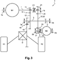
- the figure 3 illustrates a third embodiment, which differs from that described with reference to the figure 2 in that the fourth driving pinion 41 is located axially between the bearing 3a and the first driven pinion 12.
- the locking device V is arranged axially between the second driven pinion 22 (also forming the third driven pinion 32) and the bearing 3b.
- Such an embodiment can facilitate assembly operations.
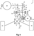
- the figure 4 illustrates a fourth embodiment, which differs from that described with reference to the figure 2 in that the first driving pinion 11 and the second driving pinion 21 are integral with the primary shaft 1 and in that the first driven pinion 12 and the second driven pinion 22 are idly mounted on the tertiary shaft 3.
- a coupling device C1a is mounted on the tertiary shaft 3 and is positioned axially between the bearing 3a and the first driven pinion 12, said coupling device C1a making it possible to lock the first driven pinion 12 on the tertiary shaft 3.
- a coupling device C1b is mounted on the tertiary shaft 3 and is positioned axially between the bearing 3b and the second driven pinion 22, said coupling device C1b making it possible to lock the second driven pinion 22 on the shaft.
- tertiary 3 It will be recalled that the second driven pinion 21 also forms the third driven pinion 32.
- the first gear 10 can be activated by the coupling device C1a
- the second gear 20 can be activated by the coupling device C1b
- the third gear 30 can be activated by the coupling device C2.
- the simultaneous activation of the first and second gears 10, 20 by the coupling devices C1a, C1b, when the ratios of the gears 10 and 20 are different, makes it possible to prevent the rotation of the tertiary shaft 3.
- the transmission device T can therefore be devoid of locking device V of the tertiary shaft.
- Such an embodiment allows the elimination of the locking device.
- the figure 5 illustrates a fifth embodiment, which differs from that described with reference to the figure 4 in that the first electric machine M1 is located axially between the second driving pinion 21 and the bearing 1b.
- the axial position of the first electric machine M1 on the primary shaft 1, or the axial position of the second electric machine M2 on the secondary shaft 2, can be changed as required, in particular depending specifications in terms of overall dimensions.
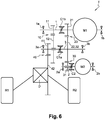
- the figure 6 illustrates a sixth embodiment, which differs from that described with reference to the figure 2 in that the first electric machine M1 is located axially between the second driving pinion 21 and the bearing 1b. Furthermore, in this embodiment, the first driving pinion 11 is integral with the primary shaft 1 and the first driven pinion 12 is mounted idly on the tertiary shaft 3. The fourth driving pinion 41 is located axially between the bearing 3a and the first driven pinion 12.
- a coupling device C1a is mounted on the tertiary shaft 3 and is positioned axially between the first driven pinion 12 and the second driven pinion 22, said coupling device C1a making it possible to lock the first driven pinion 12 on the tertiary shaft 3
- a coupling device C1b is mounted on the primary shaft 1 and is positioned axially between the first driving pinion 11 and the second driving pinion 21, said coupling device C1b making it possible to lock the second driving pinion 21 on the primary tree 1.
- the first gear 10 can be activated by the coupling device C1a
- the second gear 20 can be activated by the coupling device C1b
- the third gear 30 can be activated by the coupling device C2.
- the transmission device T can therefore be devoid of locking device V of the tertiary shaft 3.
- Such an embodiment allows the elimination of the locking device V and also makes it possible to reduce the axial size.
Landscapes
- Engineering & Computer Science (AREA)
- Chemical & Material Sciences (AREA)
- Combustion & Propulsion (AREA)
- Transportation (AREA)
- Mechanical Engineering (AREA)
- Structure Of Transmissions (AREA)
- Gear Transmission (AREA)
Abstract
Description
- La présente invention se rapporte au domaine des transmissions à au moins deux rapports de transmission destinées à être utilisées sur des véhicules automobiles électriques. On entend par véhicule automobile électrique au sens de l'invention tous les véhicules qui utilisent une machine électrique en tant que moteur principal, la machine électrique étant la seule machine motrice (véhicules purement électriques) ou associée à un moteur à combustion interne (véhicules hybrides).
- Les transmissions à plus d'un rapport, en particulier les transmissions à deux rapports, sont utilisées pour équiper des véhicules électriques et permettent un fonctionnement de la machine électrique à sa vitesse de rotation optimale, c'est-à-dire à la vitesse de rotation correspondant au rendement maximal de la machine électrique. Cet avantage s'applique à la fois à un mode de fonctionnement moteur, dans lequel la machine électrique fonctionne en tant que moteur pour générer la puissance nécessaire au déplacement du véhicule, et à un mode de fonctionnement générateur, dans lequel la machine électrique fonctionne en tant générateur pour convertir l'énergie cinétique du véhicule en énergie électrique.
- Afin de limiter les coûts et afin de compenser d'éventuelles variations du couple lors de changement de rapport, il est connu d'utiliser une transmission comportant deux machines électriques identiques. Une telle transmission est par exemple connue du document
EP 2 529 967 . - Il existe actuellement un besoin de réduire encore les coûts d'une telle transmission.
- A cet effet, l'invention propose un dispositif de transmission à au moins deux rapports de transmission, notamment pour véhicule électrique, le dispositif de transmission comprenant :
- une première machine électrique reliée à un arbre primaire,
- une deuxième machine électrique reliée à un arbre secondaire,
- un arbre tertiaire relié à l'arbre primaire et à l'arbre secondaire par l'intermédiaire d'engrenages correspondant auxdits rapports de transmission,
caractérisé en ce que la première machine électrique présente des caractéristiques techniques différentes de la deuxième machine électrique. - Les caractéristiques techniques de chaque machine électrique peuvent notamment être l'une ou plusieurs des caractéristiques suivantes : la tension d'alimentation, le courant nominal, la puissance nominale, le nombre de phases, le nombre de pôles, le rapport de la vitesse de rotation sur la tension d'alimentation, la vitesse de rotation nominale, le couple nominal, l'inertie du rotor, le courant maximal, la vitesse de rotation maximale, le couple maximal, le rendement, le type d'aimant permanent utilisé, les dimensions (diamètre, longueur, largeur), la masse.
- Le rapport de transmission est le rapport entre la vitesse de rotation d'entrée, c'est-à-dire la vitesse de rotation du rotor de la machine électrique concernée dans le cas de l'invention, et la vitesse de rotation en sortie du dispositif de transmission.
- L'utilisation de deux machines électriques présentant des caractéristiques techniques différentes permet d'utiliser une première machine électrique assurant par exemple la propulsion du véhicule dans la majorité des cas de fonctionnement, et d'utiliser la deuxième machine électrique en complément, en cas de besoin d'un couple accru, par exemple lors d'une phase d'accélération et/ou pour compenser une rupture de couple lors du changement de rapport de vitesses sur la première machine électrique. Dans un tel cas, la deuxième machine électrique peut présenter un coût plus faible que la première machine électrique et/ou des caractéristiques techniques dégradées par comparaison avec les caractéristiques techniques de la première machine électriques.
- L'arbre primaire et l'arbre tertiaire peuvent être aptes à être reliés par l'intermédiaire d'un premier engrenage correspondant à un premier rapport de transmission ou par l'intermédiaire d'un deuxième engrenage correspondant à un deuxième rapport de transmission, des moyens de couplage permettant de sélectionner ledit rapport de transmission en activant ou désactivant l'un ou l'autre desdits premier et deuxième engrenages.
- L'activation simultanée du premier engrenage et du deuxième engrenage par les moyens de couplage permet de bloquer le dispositif de transmission, notamment l'arbre tertiaire.
- Le premier engrenage et le deuxième engrenage comprennent chacun un pignon fou porté par l'arbre primaire ou l'arbre secondaire, chaque pignon fou coopérant avec un moyen de couplage, tel qu'un synchronisateur, apte à le solidariser en rotation avec l'arbre primaire ou secondaire qui le porte.
- Les premier et deuxième rapports de transmission peuvent être des rapports de transmission différents.
- L'activation d'un engrenage permet de transmettre du couple d'un arbre à l'autre, au travers de l'engrenage concerné. La désactivation d'un engrenage permet d'empêcher une telle transmission de couple.
- L'arbre secondaire et l'arbre tertiaire peuvent être aptes à être reliés par l'intermédiaire d'un troisième engrenage correspondant à un troisième rapport de transmission.
- Le troisième rapport de transmission peut être différent des premier et deuxième rapports de transmission. En variante, le troisième rapport de transmission peut être égal à l'un des premier et deuxième rapports de transmission.
- Le premier rapport de transmission peut être compris entre 26 et 10. Le deuxième rapport de transmission peut être compris entre 12 et 5. Le troisième rapport de transmission peut être compris entre 19 et 8.
- Le dispositif de transmission peut comporter des moyens de couplage aptes à activer ou désactiver le troisième engrenage.
- Les moyens de couplage peuvent comporter un actionneur piloté.
- La première machine électrique et la deuxième machine électrique peuvent être situées de part et d'autre des engrenages.
- La première machine électrique et la deuxième machine électrique peuvent être situées d'un même côté par rapport aux engrenages, de façon à réduire l'encombrement selon la direction parallèle à l'axe primaire et à l'axe secondaire.
- Le premier engrenage peut comporter un premier pignon menant disposé sur l'arbre primaire et un premier pignon mené disposé sur l'arbre tertiaire, le premier pignon menant, respectivement le premier pignon mené, étant monté fou sur l'arbre primaire, respectivement sur l'arbre tertiaire, et étant apte à être couplé en rotation à l'arbre primaire, respectivement à l'arbre tertiaire, par les moyens de couplage correspondants.
- Dans ce cas, le premier pignon mené, respectivement le premier pignon menant, peut être solidaire et relié en permanence à l'arbre tertiaire, respectivement à l'arbre primaire.
- Le deuxième engrenage peut comporter un deuxième pignon menant disposé sur l'arbre primaire et un deuxième pignon mené disposé sur l'arbre tertiaire, le deuxième pignon menant, respectivement le deuxième pignon mené, étant monté fou sur l'arbre primaire, respectivement sur l'arbre tertiaire, et étant apte à être couplé en rotation à l'arbre primaire, respectivement à l'arbre tertiaire, par les moyens de couplage correspondants.
- Dans ce cas, le deuxième pignon mené, respectivement le deuxième pignon menant, peut être solidaire et relié en permanence à l'arbre tertiaire, respectivement à l'arbre primaire.
- Le troisième engrenage peut comporter un troisième pignon menant disposé sur l'arbre secondaire et un troisième pignon mené disposé sur l'arbre tertiaire, le troisième pignon menant, respectivement le troisième pignon mené, étant monté fou sur l'arbre secondaire, respectivement sur l'arbre tertiaire, et étant apte à être couplé en rotation à l'arbre secondaire, respectivement à l'arbre tertiaire, par les moyens de couplage correspondants.
- Dans ce cas, le troisième pignon mené, respectivement le troisième pignon menant, peut être solidaire et relié en permanence à l'arbre tertiaire, respectivement à l'arbre secondaire.
- Le deuxième pignon mené et le troisième pignon mené peuvent être formés par le même pignon, de manière à réduire la complexité et le coût du dispositif de transmission.
- L'arbre primaire, l'arbre secondaire et/ou l'arbre tertiaire peuvent comporter un dispositif de verrouillage de l'arbre.
- Un tel dispositif de verrouillage peut être activé de façon à bloquer l'arbre correspondant et empêcher sa rotation en cas d'arrêt ou de stationnement du véhicule par exemple.
- Les moyens de couplage peuvent comporter au moins un crabot ou au moins un synchroniseur, apte à activer l'engrenage concerné.
- Dans le cas d'un synchroniseur, l'engrenage peut être activé lorsque la vitesse de rotation de l'arbre concerné atteint une vitesse de consigne.
- En variante ou en complément, les moyens de couplage peuvent également comporter un embrayage à friction, par exemple un embrayage multidisques humide.
- Un palier support peut être situé à chaque extrémité de l'arbre primaire, de l'arbre secondaire et/ou de l'arbre tertiaire.
- Un différentiel peut être relié à l'arbre tertiaire par l'intermédiaire d'un engrenage de différentiel, ledit différentiel étant apte à être relié aux roues du véhicule.
- Le différentiel autorise les roues motrices du véhicule à tourner à des vitesses différentes lors du passage d'une courbe ou d'un virage. Les roues situées à l'extérieur du virage peuvent alors tourner plus vite que celles situées à l'intérieur du virage.
- La première machine électrique peut présenter des caractéristiques techniques inférieures à la deuxième machine électrique.
- Les caractéristiques techniques peuvent concerner la puissance nominale de la première machine électrique et la puissance nominale de la deuxième machine électrique.
- Les caractéristiques techniques peuvent concerner le couple nominal de la première machine électrique et le couple nominal de la deuxième machine électrique.
- Plusieurs rapports de vitesses peuvent être associés à la première machine électrique. La deuxième machine électrique peut alors être apte à compenser une rupture de couple lors du changement de rapport de vitesses sur la première machine électrique.
- L'invention sera mieux comprise et d'autres détails, caractéristiques et avantages de l'invention apparaîtront à la lecture de la description suivante faite à titre d'exemple non limitatif en référence aux dessins annexés dans lesquels :
- la
figure 1 est une vue schématique d'un dispositif de transmission de couple selon une première forme de réalisation de l'invention, - la
figure 2 est une vue schématique d'un dispositif de transmission de couple selon une deuxième forme de réalisation de l'invention, - la
figure 3 est une vue schématique d'un dispositif de transmission de couple selon une troisième forme de réalisation de l'invention, - la
figure 4 est une vue schématique d'un dispositif de transmission de couple selon une quatrième forme de réalisation de l'invention, - la
figure 5 est une vue schématique d'un dispositif de transmission de couple selon une cinquième forme de réalisation de l'invention, - la
figure 6 est une vue schématique d'un dispositif de transmission de couple selon une sixième forme de réalisation de l'invention. - Sur toutes les figures, les éléments ayant des fonctions identiques portent les mêmes numéros de référence.
- Les réalisations suivantes sont des exemples. Bien que la description se réfère à plusieurs modes de réalisation, ceci ne signifie pas nécessairement que chaque référence concerne le même mode de réalisation, ou que les caractéristiques s'appliquent seulement à un seul mode de réalisation. De simples caractéristiques de différents modes de réalisation peuvent également être combinées pour fournir d'autres réalisations.
- En relation avec les
figures 1 à 6 , on observe les éléments essentiels d'une chaine cinématique de véhicule propulsé par une première machine électrique M1 et une seconde machine électrique M2, reliées aux roues R1, R2 du véhicule par l'intermédiaire d'un dispositif de transmission T. Le dispositif de transmission T fait office de réducteur entre les machines électriques M1, M2 et les roues R1, R2 du véhicule, c'est-à-dire qu'il a pour but de modifier le rapport de vitesses et/ou de couple entre l'arbre de sortie de la machine électrique M1, M2 concernée et les roues R1, R2 du véhicule. - Chaque machine électrique M1, M2 peut être par exemple être une machine électrique synchrone à aimants permanents fonctionnant à basse tension, en particulier une tension comprise entre 30 et 60 Volts, par exemple de l'ordre de 48 Volts pour au moins l'une des machines électriques M1, M2.
- La première machine électrique M1 présente des caractéristiques techniques différentes de la deuxième machine électrique M2.
- Les caractéristiques techniques de chaque machine électrique peuvent notamment être l'une ou plusieurs des caractéristiques suivantes : la tension d'alimentation, le courant nominal, la puissance nominale, le nombre de phases, le nombre de pôles, le rapport de la vitesse de rotation sur la tension d'alimentation, la vitesse de rotation nominale, le couple nominal, l'inertie du rotor, le courant maximal, la vitesse de rotation maximale, le couple maximal, le rendement, le type d'aimant permanent utilisé, les dimensions, la masse.
- Le dispositif de transmission T de la
figure 1 comprend un arbre primaire 1 qui est formé par l'arbre de sortie de la première machine électrique M1. - En variante, l'arbre primaire 1 peut être accouplé à l'arbre de sortie de la première machine électrique M1. Cet accouplement est alors homocinétique et peut être tout type d'accouplement mécanique entre deux arbres, comme par exemple un accouplement avec cannelures.
- Le dispositif de transmission T comprend également un arbre secondaire 2 qui est formé par l'arbre de sortie de la deuxième machine électrique M2.
- En variante et comme précédemment, l'arbre secondaire 2 peut être accouplé à l'arbre de sortie de la deuxième machine électrique M2. Cet accouplement est alors homocinétique et peut être tout type d'accouplement mécanique entre deux arbres, comme par exemple un accouplement avec cannelures.
- Le dispositif de transmission T comprend par ailleurs un arbre tertiaire 3. L'arbre tertiaire 3 est apte à être relié à un différentiel D lui-même relié aux roues R1, R2 du véhicule.
- Un premier engrenage 10 correspondant à un premier rapport de transmission comprend un premier pignon menant 11 disposé sur l'arbre primaire 1 et un premier pignon mené 12 disposé sur l'arbre tertiaire 3. Le premier pignon menant 11 et le premier pignon mené 12 engrènent en permanence.
- Un deuxième engrenage 20 correspondant à un second rapport de transmission comprend un deuxième pignon menant 21 disposé sur l'arbre primaire 1 et un deuxième pignon mené 22 disposé sur l'arbre tertiaire 3. Le deuxième pignon menant 21 et le deuxième pignon mené 22 engrènent en permanence.
- Le premier pignon menant 11 et le deuxième pignon menant 21 sont montés fous sur l'arbre primaire 1, par l'intermédiaire de roulements à aiguilles, et peut ainsi tourner par rapport à l'arbre primaire 1.
- Le premier pignon mené 12 et le deuxième pignon mené 22 sont solidaires de l'arbre tertiaire 3.
- Le rapport de réduction entre le premier pignon menant 11 et le premier pignon mené 12 peut par exemple être compris entre 5 et 2.
- Le rapport de réduction entre le deuxième pignon menant 21 et le deuxième pignon mené 22 peut par exemple être compris entre 3,5 et 1.
- Un troisième engrenage 30 correspondant à un troisième rapport de transmission comprend un troisième pignon menant 31 disposé sur l'arbre secondaire 2 et un deuxième pignon mené 32 disposé sur l'arbre tertiaire 3. Le deuxième pignon menant 31 et le deuxième pignon mené 32 engrènent en permanence.
- Le troisième pignon menant 31 est solidaire de l'arbre secondaire 2. Le troisième pignon mené 32 est monté fou sur l'arbre tertiaire 3, par l'intermédiaire de roulements à aiguilles, et peut ainsi tourner par rapport à l'arbre tertiaire 3.
- Le rapport de réduction entre le troisième pignon menant 31 et le troisième pignon mené 32 peut par exemple être compris entre 5 et 1,5.
- Un quatrième engrenage correspondant à un engrenage 40 de différentiel D comprend un quatrième pignon menant 41 disposé sur l'arbre tertiaire 3 et un quatrième pignon mené 42 correspondant à l'entrée du différentiel D. Le quatrième pignon menant 41 est monté fixe sur l'arbre tertiaire. Le quatrième pignon menant 41 et le quatrième pignon mené 42 engrènent en permanence.
- Le rapport de réduction entre le quatrième pignon menant 41 et le quatrième pignon mené 42 peut par exemple être compris entre 5 et 2,5.
- Les quatre engrenages 10, 20, 30, 40 sont orientés de manière parallèle. De la même manière, les trois arbres 1, 2, 3 sont orientés de manière parallèle. Les différents pignons 11, 12, 21, 22, 31, 32, 41, 42 sont des pièces distinctes les unes des autres, dans la forme de réalisation illustrée à la
figure 1 , et ont des dentures droites. En variante, ces pignons peuvent avoir des dentures obliques, hélicoïdales ou à chevrons. - Deux chemins de couple sont donc possibles entre l'arbre de sortie de la première machine électrique M1 et les roues R1, R2 du véhicule. Un premier chemin de couple passe par le premier engrenage 10 puis l'engrenage 40 de différentiel D. Un deuxième chemin de couple passe par le deuxième engrenage 20 puis l'engrenage 40 de différentiel D.
- Un autre chemin de couple passant par le troisième engrenage 30 et l'engrenage 40 de différentiel D permet de relier la deuxième machine électrique M2 et les roues R1, R2 du véhicule.
- La première machine électrique M1 peut être utilisée seule, ou en complément de la deuxième machine électrique M2, afin de déplacer le véhicule. En particulier, la première machine électrique M1 peut être utilisée seule lorsque le couple requis est inférieur à un couple déterminé, la seconde machine électrique M2 pouvant par exemple être utilisée lorsque le couple requis est supérieur audit couple déterminé.
- La deuxième machine électrique M2 peut ainsi être utilisée moins fréquemment que la première machine électrique M1, ce qui explique notamment le fait que la seconde machine électrique M2 peut présenter des caractéristiques techniques différentes de la première machine électrique M1, tel par exemple qu'un rendement plus faible, qu'un couple nominal ou maximal plus faible, ou encore des dimensions réduites.
- Afin de sélectionner le chemin de couple approprié en fonction notamment des conditions de conduite (montée, descente, conduite sur autoroute, conduite, urbaine...), des dispositifs de couplage C1, C2 sont disposés dans le dispositif de transmission T afin de sélectionner le chemin de couple approprié passant par le premier engrenage 10, par le deuxième engrenage 20 ou par le troisième engrenage 30.
- En particulier, un premier dispositif de couplage C1 est disposé sur l'arbre primaire 1 et permet d'activer sélectivement le premier engrenage 10 ou le deuxième engrenage 20, et de désactiver sélectivement le deuxième engrenage 20 ou respectivement le premier engrenage 10.
- Un deuxième dispositif de couplage C2 permet d'activer ou de désactiver le troisième engrenage 30, indépendamment du premier dispositif de couplage C1.
- Chaque dispositif de couplage C1, C2 est ici formé par un crabot ou un synchroniseur.
- Le premier dispositif de couplage C1 est monté sur l'arbre primaire 1 et est positionné axialement entre le premier pignon menant 11 et le deuxième pignon menant 21. Le premier dispositif de couplage C1 permet de verrouiller soit le premier pignon menant 11, soit le deuxième pignon menant 21, sur l'arbre primaire 1. Le verrouillage intervient par exemple lorsque la vitesse de rotation du premier pignon menant 11 ou du deuxième pignon menant 21 est égale ou proche de la vitesse de rotation de l'arbre primaire 1.
- Le deuxième dispositif de couplage C2 est monté sur l'arbre tertiaire 3 et permet de verrouiller le troisième pignon mené 32. Le verrouillage intervient par exemple lorsque la vitesse de rotation du troisième pignon mené 32 est égale ou proche de la vitesse de rotation de l'arbre tertiaire 3.
- L'actionnement des dispositifs de couplage C1, C2 peut être piloté en fonction par exemple des conditions de fonctionnement (vitesse du véhicule, couple requis). Le pilotage des dispositifs de couplage C1, C2 peut être réalisé par un calculateur embarqué dans le véhicule. Ledit calculateur peut également être utilisé afin de piloter l'alimentation des machines électriques M1, M2.
- L'arbre tertiaire est par ailleurs équipé d'un dispositif de verrouillage V apte à bloquer ledit arbre tertiaire 3 en cas d'arrêt ou de stationnement du véhicule par exemple.
- Le stator de chaque machine électrique M1, M2 peut être fixé sur un boîtier du dispositif de transmission T par tout moyen de fixation, par exemple des vis. L'arbre primaire 1, l'arbre secondaire 2 et l'arbre tertiaire 3 sont chacun supportés par des paliers situés à chacune des extrémités des arbres.
- En particulier, l'arbre primaire 1 est supporté par les paliers 1a et 1b, l'arbre secondaire 2 est supporté par les paliers 2a et 2b, et l'arbre tertiaire 3 est supporté par les paliers 3a et 3b. Chacun de ces paliers se présente sous la forme d'un roulement à billes ayant une bague interne en contact avec l'arbre 1, 2, 3 et une bague externe logée dans le boitier du dispositif de transmission T.
- L'arbre primaire 1 comporte axialement, du palier 1a vers le palier 1b, la machine électrique M1, le premier pignon menant 11, les moyens de couplage C1 et le deuxième pignon menant 21.
- L'arbre secondaire 2 comporte axialement, du palier 2a vers le palier 2b, le troisième pignon menant 31 et la deuxième machine électrique M2. Les palier 1b et 2a sont proches l'un de l'autre tandis que les paliers 1a et 2b sont éloignés l'un de l'autre.
- L'arbre tertiaire 3 comporte axialement, du palier 3a vers le palier 3b, le dispositif de verrouillage V, le premier pignon mené 12, le quatrième pignon menant 41, le deuxième pignon mené 22, le troisième pignon mené 32 et les deuxièmes moyens de couplage C2.
- Dans la forme de réalisation illustrée à la
figure 1 , les machines électriques M1 et M2 sont situées axialement de part et d'autre des engrenages 10, 20, 30 et/ou 40. - En fonctionnement, les moyens de pilotage permettent de sélectionner le ou les chemins de couple à appliquer et actionnent les moyens de couplage C1 et C2 en conséquence.
- Le premier chemin de couple permettant de transférer le couple de la première machine électrique M1 aux roues R1, R2, par l'intermédiaire du premier engrenage 10 et du quatrième engrenage 40 peut être utilisé pour une faible vitesse d'avance du véhicule, par exemple pour une vitesse inférieure à 90 km/h. Un tel cas de fonctionnement peut notamment se présenter au démarrage du véhicule ou lors d'une montée.
- Le deuxième chemin de couple permettant de transférer le couple de la première machine électrique M1 aux roues R1, R2, par l'intermédiaire du deuxième engrenage 20 et du quatrième engrenage 40 peut être utilisé pour une vitesse élevée d'avance du véhicule, par exemple pour une vitesse supérieure ou égale à 30 km/h. Un tel cas de fonctionnement peut notamment se présenter lors d'une conduite sur route du véhicule.
- Le troisième chemin de couplage permettant de transférer le couple de la deuxième machine électrique M2 aux roues R1, R2, par l'intermédiaire du troisième engrenage 30 et du quatrième engrenage 40 peut être utilisé, seul ou de préférence en complément du premier chemin de couple ou du deuxième chemin de couple.
- L'utilisation du troisième chemin de couple en complément du premier chemin de couple ou du deuxième chemin de couple permet d'augmenter le couple total transmis aux roues R1, R2. Par voie de conséquence, il est possible d'optimiser le dimensionnement des première et deuxième machines électriques M1, M2 de façon à répondre aux différents cas de fonctionnement tout en limitant les coûts d'un tel dispositif de transmission.
- La
figure 2 illustre un dispositif de transmission selon une deuxième forme de réalisation de l'invention, qui diffère de la forme de réalisation décrite en référence à lafigure 1 en ce que le troisième pignon menant 31 est monté fou sur l'arbre secondaire 2 et en ce que le troisième pignon 32 mené et le deuxième pignon mené 22 forment un seul et même pignon, solidaire de l'arbre tertiaire 3. Dans cette forme de réalisation également, le deuxième dispositif de couplage C2 est monté sur l'arbre secondaire 2 et permet de verrouiller le troisième pignon menant 31. Le verrouillage intervient par exemple lorsque la vitesse de rotation du troisième pignon menant 31 est égale ou proche de la vitesse de rotation de l'arbre secondaire 2. - Une telle forme de réalisation permet de limiter le nombre de pignons utilisés, et donc de réduire le coût et la masse du dispositif de transmission T. Une telle forme de réalisation permet également de limiter l'encombrement axial.
- La
figure 3 illustre une troisième forme de réalisation, qui diffère de celle décrite en référence à lafigure 2 en ce que le quatrième pignon menant 41 est situé axialement entre le palier 3a et le premier pignon mené 12. Par ailleurs, le dispositif de verrouillage V est disposé axialement entre le deuxième pignon mené 22 (formant également le troisième pignon mené 32) et le palier 3b. - Une telle forme de réalisation peut permettre de faciliter les opérations d'assemblage.
- La
figure 4 illustre une quatrième forme de réalisation, qui diffère de celle décrite en référence à lafigure 2 en ce que le premier pignon menant 11 et le deuxième pignon menant 21 sont solidaires de l'arbre primaire 1 et en ce que le premier pignon mené 12 et le deuxième pignon mené 22 sont montés fous sur l'arbre tertiaire 3. Dans cette forme de réalisation également, un dispositif de couplage C1a est monté sur l'arbre tertiaire 3 et est positionné axialement entre le palier 3a et le premier pignon mené 12, ledit dispositif de couplage C1a permettant de verrouiller le premier pignon mené 12 sur l'arbre tertiaire 3. Par ailleurs, un dispositif de couplage C1b est monté sur l'arbre tertiaire 3 et est positionné axialement entre le palier 3b et le deuxième pignon mené 22, ledit dispositif de couplage C1b permettant de verrouiller le deuxième pignon mené 22 sur l'arbre tertiaire 3. On rappelle que le deuxième pignon mené 21 forme également le troisième pignon mené 32. - En d'autres termes, le premier engrenage 10 peut être activé par le dispositif de couplage C1a, le deuxième engrenage 20 peut être activé par le dispositif de couplage C1b et le troisième engrenage 30 peut être activé par le dispositif de couplage C2.
- On notera par ailleurs que l'activation simultanée des premier et deuxième engrenages 10, 20 par les dispositifs de couplage C1a, C1b, lorsque les rapports des engrenages 10 et 20 sont différents, permet d'empêcher la rotation de l'arbre tertiaire 3. Dans cette forme de réalisation, le dispositif de transmission T peut donc être dépourvu de dispositif de verrouillage V de l'arbre tertiaire.
- Une telle forme de réalisation permet la suppression du dispositif de verrouillage.
- La
figure 5 illustre une cinquième forme de réalisation, qui diffère de celle décrite en référence à lafigure 4 en ce que la première machine électrique M1 est située axialement entre le deuxième pignon menant 21 et le palier 1b. - De manière plus générale, la position axiale de la première machine électrique M1 sur l'arbre primaire 1, ou la position axiale de la deuxième machine électrique M2 sur l'arbre secondaire 2, peut être modifiée en fonction des besoins, en particulier en fonction des spécifications en termes d'encombrement.
- La
figure 6 illustre une sixième forme de réalisation, qui diffère de celle décrite en référence à lafigure 2 en ce que la première machine électrique M1 est située axialement entre le deuxième pignon menant 21 et le palier 1b. Par ailleurs, dans cette forme de réalisation, le premier pignon menant 11 est solidaire de l'arbre primaire 1 et le premier pignon mené 12 est monté fou sur l'arbre tertiaire 3. Le quatrième pignon menant 41 est situé axialement entre le palier 3a et le premier pignon mené 12. - De plus, dans la forme de réalisation de la
figure 6 , un dispositif de couplage C1a est monté sur l'arbre tertiaire 3 et est positionné axialement entre le premier pignon mené 12 et le deuxième pignon mené 22, ledit dispositif de couplage C1a permettant de verrouiller le premier pignon mené 12 sur l'arbre tertiaire 3. Par ailleurs, un dispositif de couplage C1b est monté sur l'arbre primaire 1 et est positionné axialement entre le premier pignon menant 11 et le deuxième pignon menant 21, ledit dispositif de couplage C1b permettant de verrouiller le deuxième pignon menant 21 sur l'arbre primaire 1. - En d'autres termes, le premier engrenage 10 peut être activé par le dispositif de couplage C1a, le deuxième engrenage 20 peut être activé par le dispositif de couplage C1b et le troisième engrenage 30 peut être activé par le dispositif de couplage C2.
- On notera par ailleurs que l'activation des premier et deuxième engrenages 10, 20 par les dispositifs de couplage C1a, C1b, lorsque les rapports des engrenages 10 et 20 sont différents, permet notamment d'empêcher la rotation de l'arbre tertiaire 3. Dans cette forme de réalisation, le dispositif de transmission T peut donc être dépourvu de dispositif de verrouillage V de l'arbre tertiaire 3.
- Une telle forme de réalisation permet la suppression du dispositif de verrouillage V et permet également de réduire l'encombrement axial.
Claims (15)
- Dispositif de transmission (T) à au moins deux rapports de transmission, notamment pour véhicule électrique, le dispositif de transmission (T) comprenant :- une première machine électrique (M1) reliée à un arbre primaire (1),- une deuxième machine électrique (M2) reliée à un arbre secondaire (2),- un arbre tertiaire (3) relié à l'arbre primaire (1) et à l'arbre secondaire (2) par l'intermédiaire d'engrenages (10, 20, 30) correspondant auxdits rapports de transmission,
caractérisé en ce que la première machine électrique (M1) présente des caractéristiques techniques différentes de la deuxième machine électrique (M2). - Dispositif de transmission (T) selon la revendication 1, caractérisé en ce que l'arbre primaire (1) et l'arbre tertiaire (3) sont aptes à être reliés par l'intermédiaire d'un premier engrenage (10) correspondant à un premier rapport de transmission ou par l'intermédiaire d'un deuxième engrenage (20) correspondant à un deuxième rapport de transmission, des moyens de couplage (C1, C1a, C1b) permettant de sélectionner ledit rapport de transmission en activant ou désactivant l'un ou l'autre desdits premier et deuxième engrenages (10, 20).
- Dispositif de transmission (T) selon la revendication 1 ou 2, caractérisé en ce que l'activation simultanée du premier engrenage (10) et du deuxième engrenage (20) par les moyens de couplage (C1a, C1b) permet de bloquer le dispositif de transmission, notamment l'arbre tertiaire (3).
- Dispositif de transmission (T) selon la revendication 1 à 3, caractérisé en ce que l'arbre secondaire (2) et l'arbre tertiaire (3) sont aptes à être reliés par l'intermédiaire d'un troisième engrenage (30) correspondant à un troisième rapport de transmission.
- Dispositif de transmission (T) selon la revendication 4, caractérisé en ce qu'il comporte des moyens de couplage (C2) aptes à activer ou désactiver le troisième engrenage.
- Dispositif de transmission (T) selon l'une des revendications 1 à 5, caractérisé en ce que la première machine électrique (M1) et la deuxième machine électrique (M2) sont situées de part et d'autre des engrenages (10, 20, 30).
- Dispositif de transmission (T) selon l'une des revendications 1 à 5, caractérisé en ce que la première machine électrique (M1) et la deuxième machine électrique (M2) sont situées d'un même côté par rapport aux engrenages (10, 20, 30).
- Dispositif de transmission (T) selon l'une des revendications 1 à 7, caractérisé en ce que le premier engrenage (10) comporte un premier pignon menant (11) disposé sur l'arbre primaire (1) et un premier pignon mené (12) disposé sur l'arbre tertiaire (3), le premier pignon menant (11), respectivement le premier pignon mené (12), étant monté fou sur l'arbre primaire (1), respectivement sur l'arbre tertiaire (3), et étant apte à être couplé en rotation à l'arbre primaire (1), respectivement à l'arbre tertiaire (3), par les moyens de couplage correspondants (C1, C1a).
- Dispositif de transmission (T) selon l'une des revendications 1 à 8, caractérisé en ce que le deuxième engrenage (20) comporte un deuxième pignon menant (21) disposé sur l'arbre primaire (1) et un deuxième pignon mené (22) disposé sur l'arbre tertiaire (3), le deuxième pignon menant (21), respectivement le deuxième pignon mené (22), étant monté fou sur l'arbre primaire (1), respectivement sur l'arbre tertiaire (3), et étant apte à être couplé en rotation à l'arbre primaire (1), respectivement à l'arbre tertiaire (3), par les moyens de couplage correspondants (C1, C1b).
- Dispositif de transmission (T) selon l'une des revendications 1 à 9, caractérisé en ce que le troisième engrenage (30) comporte un troisième pignon menant (31) disposé sur l'arbre secondaire (2) et un troisième pignon mené (32) disposé sur l'arbre tertiaire (3), le troisième pignon menant (31), respectivement le troisième pignon mené (32), étant monté fou sur l'arbre secondaire (2), respectivement sur l'arbre tertiaire (3), et étant apte à être couplé en rotation à l'arbre secondaire (2), respectivement à l'arbre tertiaire (3), par les moyens de couplage correspondants (C2).
- Dispositif de transmission (T) selon les revendications 8 et 10, caractérisé en ce que le deuxième pignon mené (22) et le troisième pignon mené (32) sont formés par le même pignon.
- Dispositif de transmission (T) selon l'une des revendications 1 à 11, caractérisé en ce que l'arbre primaire (1), l'arbre secondaire (2) et/ou l'arbre tertiaire (3) comportent un dispositif de verrouillage (V) de l'arbre.
- Dispositif de transmission (T) selon l'une des revendications 1 à 12, caractérisé en ce que les moyens de couplage (C1, C1a, C1b, C2) peuvent comporter au moins un crabot ou au moins un synchroniseur, apte à activer l'engrenage (10, 20, 30) concerné.
- Dispositif de transmission (T) selon l'une des revendications 1 à 13, caractérisé en ce que la première machine électrique (M) présente des caractéristiques techniques inférieures à la deuxième machine électrique (M2).
- Dispositif de transmission (T) selon l'une des revendications 1 à 14, caractérisé en ce que les caractéristiques techniques concernent la puissance nominale de la première machine électrique (M1) et la puissance nominale de la deuxième machine électrique (M2), ou le couple nominal de la première machine électrique (M1) et le couple nominal de la deuxième machine électrique (M2).
Applications Claiming Priority (1)
| Application Number | Priority Date | Filing Date | Title |
|---|---|---|---|
| FR1855281A FR3082461B1 (fr) | 2018-06-15 | 2018-06-15 | Dispositif de transmission, notamment pour vehicule electrique |
Publications (2)
| Publication Number | Publication Date |
|---|---|
| EP3581416A1 true EP3581416A1 (fr) | 2019-12-18 |
| EP3581416B1 EP3581416B1 (fr) | 2021-03-31 |
Family
ID=63407429
Family Applications (1)
| Application Number | Title | Priority Date | Filing Date |
|---|---|---|---|
| EP19180367.5A Active EP3581416B1 (fr) | 2018-06-15 | 2019-06-14 | Dispositif de transmission, notamment pour véhicule électrique |
Country Status (3)
| Country | Link |
|---|---|
| EP (1) | EP3581416B1 (fr) |
| CN (1) | CN110605963A (fr) |
| FR (1) | FR3082461B1 (fr) |
Cited By (7)
| Publication number | Priority date | Publication date | Assignee | Title |
|---|---|---|---|---|
| CN111497587A (zh) * | 2020-05-28 | 2020-08-07 | 格特拉克(江西)传动系统有限公司 | 一种混合动力驱动系统、控制方法及车辆 |
| AT522931A1 (de) * | 2019-11-12 | 2021-03-15 | Avl Commercial Driveline & Tractor Eng Gmbh | Elektrisch angetriebene achsanordnung für ein fahrzeug |
| CN112918238A (zh) * | 2021-02-10 | 2021-06-08 | 重庆青山工业有限责任公司 | 纵置双电机混合动力系统 |
| DE102020115666A1 (de) | 2020-06-15 | 2021-12-16 | Iav Gmbh Ingenieurgesellschaft Auto Und Verkehr | Elektrischer Fahrzeugantrieb mit Mehrganggetriebe |
| DE102020115664A1 (de) | 2020-06-15 | 2021-12-16 | Iav Gmbh Ingenieurgesellschaft Auto Und Verkehr | Elektrischer Fahrzeugantrieb mit Mehrganggetriebe |
| CN115853974A (zh) * | 2022-12-06 | 2023-03-28 | 成都泰鑫兴科技发展有限公司 | 一种带扭换挡装置及其工作方法 |
| FR3137618A1 (fr) * | 2022-07-11 | 2024-01-12 | Valeo Equipements Electriques Moteur | Architecture de traction pour véhicule automobile à double machines électriques tournantes |
Families Citing this family (3)
| Publication number | Priority date | Publication date | Assignee | Title |
|---|---|---|---|---|
| CN112140857B (zh) * | 2019-06-27 | 2024-05-10 | 宇通客车股份有限公司 | 一种纯电动汽车及其电驱动动力系统 |
| KR102440057B1 (ko) * | 2020-12-16 | 2022-09-06 | 한호산업(주) | 전기 차량용 변속기 |
| JP7572550B2 (ja) * | 2021-06-10 | 2024-10-23 | 株式会社ユニバンス | 動力伝達装置 |
Citations (7)
| Publication number | Priority date | Publication date | Assignee | Title |
|---|---|---|---|---|
| GB757515A (en) * | 1952-09-29 | 1956-09-19 | Patentverwertung Reimers W Gmbh | An improved electrical variable speed system or gear |
| US20040144576A1 (en) * | 2003-01-16 | 2004-07-29 | Takenori Hashimoto | Driving apparatus for an electric vehicle |
| DE102010024147A1 (de) * | 2009-07-02 | 2011-01-05 | Luk Lamellen Und Kupplungsbau Beteiligungs Kg | Zwei-Gang-Getriebe und Verfahren zur Steuerung eines Zwei-Gang-Getriebes |
| EP2436950A2 (fr) * | 2010-10-01 | 2012-04-04 | Deere & Company | Commande électromécanique dotée d'une plage étendue de vitesses à puissance constante |
| EP2529967A1 (fr) | 2011-06-03 | 2012-12-05 | Oerlikon Graziano S.P.A. | Propulsion électrique pour véhicule |
| FR3053007A1 (fr) * | 2016-06-28 | 2017-12-29 | France Reducteurs | Transmission, notamment pour engin roulant, et engin roulant equipe d'une telle transmission |
| US9951850B2 (en) * | 2014-04-04 | 2018-04-24 | Gkn Automotive Limited | Drive assembly for an electric drive |
Family Cites Families (6)
| Publication number | Priority date | Publication date | Assignee | Title |
|---|---|---|---|---|
| DE102011078043A1 (de) * | 2011-06-24 | 2012-12-27 | Robert Bosch Gmbh | Verriegelung eines mehrstufigen Getriebes |
| CN102795103A (zh) * | 2012-09-05 | 2012-11-28 | 刘丽君 | 一种带有中间轴的双电机动力总成 |
| CN103770639A (zh) * | 2013-12-12 | 2014-05-07 | 袁一卿 | 用于纯电动车辆的电动力总成 |
| CN106274464B (zh) * | 2015-05-29 | 2019-09-10 | 上海汽车集团股份有限公司 | 纯电动车辆的双电机动力系统和控制方法 |
| CN204921928U (zh) * | 2015-08-19 | 2015-12-30 | 上海汽车变速器有限公司 | 电动汽车变速器齿轴系统 |
| CN207360088U (zh) * | 2017-11-01 | 2018-05-15 | 南京越博动力系统股份有限公司 | 一种电动车用双电机两档变速箱传动系统 |
-
2018
- 2018-06-15 FR FR1855281A patent/FR3082461B1/fr active Active
-
2019
- 2019-06-14 EP EP19180367.5A patent/EP3581416B1/fr active Active
- 2019-06-14 CN CN201910515589.1A patent/CN110605963A/zh active Pending
Patent Citations (7)
| Publication number | Priority date | Publication date | Assignee | Title |
|---|---|---|---|---|
| GB757515A (en) * | 1952-09-29 | 1956-09-19 | Patentverwertung Reimers W Gmbh | An improved electrical variable speed system or gear |
| US20040144576A1 (en) * | 2003-01-16 | 2004-07-29 | Takenori Hashimoto | Driving apparatus for an electric vehicle |
| DE102010024147A1 (de) * | 2009-07-02 | 2011-01-05 | Luk Lamellen Und Kupplungsbau Beteiligungs Kg | Zwei-Gang-Getriebe und Verfahren zur Steuerung eines Zwei-Gang-Getriebes |
| EP2436950A2 (fr) * | 2010-10-01 | 2012-04-04 | Deere & Company | Commande électromécanique dotée d'une plage étendue de vitesses à puissance constante |
| EP2529967A1 (fr) | 2011-06-03 | 2012-12-05 | Oerlikon Graziano S.P.A. | Propulsion électrique pour véhicule |
| US9951850B2 (en) * | 2014-04-04 | 2018-04-24 | Gkn Automotive Limited | Drive assembly for an electric drive |
| FR3053007A1 (fr) * | 2016-06-28 | 2017-12-29 | France Reducteurs | Transmission, notamment pour engin roulant, et engin roulant equipe d'une telle transmission |
Cited By (9)
| Publication number | Priority date | Publication date | Assignee | Title |
|---|---|---|---|---|
| AT522931A1 (de) * | 2019-11-12 | 2021-03-15 | Avl Commercial Driveline & Tractor Eng Gmbh | Elektrisch angetriebene achsanordnung für ein fahrzeug |
| CN111497587A (zh) * | 2020-05-28 | 2020-08-07 | 格特拉克(江西)传动系统有限公司 | 一种混合动力驱动系统、控制方法及车辆 |
| DE102020115666A1 (de) | 2020-06-15 | 2021-12-16 | Iav Gmbh Ingenieurgesellschaft Auto Und Verkehr | Elektrischer Fahrzeugantrieb mit Mehrganggetriebe |
| DE102020115664A1 (de) | 2020-06-15 | 2021-12-16 | Iav Gmbh Ingenieurgesellschaft Auto Und Verkehr | Elektrischer Fahrzeugantrieb mit Mehrganggetriebe |
| DE102020115664B4 (de) | 2020-06-15 | 2023-06-15 | Iav Gmbh Ingenieurgesellschaft Auto Und Verkehr | Elektrischer Fahrzeugantrieb mit Mehrganggetriebe |
| DE102020115666B4 (de) | 2020-06-15 | 2023-06-29 | Iav Gmbh Ingenieurgesellschaft Auto Und Verkehr | Elektrischer Fahrzeugantrieb mit Mehrganggetriebe |
| CN112918238A (zh) * | 2021-02-10 | 2021-06-08 | 重庆青山工业有限责任公司 | 纵置双电机混合动力系统 |
| FR3137618A1 (fr) * | 2022-07-11 | 2024-01-12 | Valeo Equipements Electriques Moteur | Architecture de traction pour véhicule automobile à double machines électriques tournantes |
| CN115853974A (zh) * | 2022-12-06 | 2023-03-28 | 成都泰鑫兴科技发展有限公司 | 一种带扭换挡装置及其工作方法 |
Also Published As
| Publication number | Publication date |
|---|---|
| EP3581416B1 (fr) | 2021-03-31 |
| CN110605963A (zh) | 2019-12-24 |
| FR3082461B1 (fr) | 2023-01-20 |
| FR3082461A1 (fr) | 2019-12-20 |
Similar Documents
| Publication | Publication Date | Title |
|---|---|---|
| EP3581416B1 (fr) | Dispositif de transmission, notamment pour véhicule électrique | |
| EP1453694B1 (fr) | Dispositif de transmission de puissance a au moins deux trains epicyclo daux | |
| EP1875104B1 (fr) | Dispositif de transmission de puissance d'un vehicule automobile muni d'un mecanisme a roues libres entrainant une pompe a huile | |
| EP1232891B1 (fr) | Système de transmission de mouvement pour véhicules à propulsion hybride | |
| WO2020025775A1 (fr) | Systeme de propulsion pour vehicule electrique | |
| FR2814121A1 (fr) | Groupe motopropulseur pour un vehicule automobile a propulsion hybride | |
| FR2811395A1 (fr) | Boite de vitesses pour vehicule hybride | |
| FR3080069A1 (fr) | Chaine de traction optimisee de vehicule automobile comprenant deux machines electriques tournantes | |
| EP4011670A1 (fr) | Module hybride | |
| EP2123498A1 (fr) | Dispositif de traction électrique pour véhicule hybride | |
| EP4094963A1 (fr) | Sous-ensemble hybride d'entraînement d'un véhicule, groupe moteur hybride et procédé d'entraînement hybride | |
| WO2019122553A1 (fr) | Chaîne de traction améliorée de véhicule automobile comprenant deux machines électriques tournantes | |
| EP1068978B1 (fr) | Boíte de vitesses mécanique en ligne, pour véhicule à propulsion hybride | |
| FR3107746A1 (fr) | sous-ensemble hybride d’entraînement d’un véhicule | |
| EP4046843A1 (fr) | Module motorisé, sous-ensemble hybride d'entraînement d'un véhicule et méthode d'engagement d'un crabot | |
| EP3462058A1 (fr) | Dispositif de transmission de vitesse avec marche arriere pour le deplacement d'un vehicule automobile, notamment d'un vehicule motorise a au moins deux-roues | |
| EP2816253B1 (fr) | Réducteur épicycloïdal pour actionneur d enroulement et de déroulement | |
| FR2811267A1 (fr) | Groupe motopropulseur pour vehicule a motorisation hybride avec deux machines electriques concentriques | |
| FR3077536A1 (fr) | Dispositif de transmission a deux vitesses pour vehicule electrique | |
| EP4279308B1 (fr) | Sous-ensemble hybride d'entraînement d'un véhicule | |
| FR3154045A1 (fr) | Dispositif d’entrainement mécanique d’un arbre de transmission comprenant deux machines tournantes | |
| FR3115240A1 (fr) | Boite de vitesses comprenant une machine electrique motrice | |
| FR3137618A1 (fr) | Architecture de traction pour véhicule automobile à double machines électriques tournantes | |
| EP4048538A1 (fr) | Système de propulsion pour un véhicule | |
| WO2022084594A1 (fr) | Boite de vitesses integrant une machine motrice electrique |
Legal Events
| Date | Code | Title | Description |
|---|---|---|---|
| STAA | Information on the status of an ep patent application or granted ep patent |
Free format text: STATUS: EXAMINATION IS IN PROGRESS |
|
| PUAI | Public reference made under article 153(3) epc to a published international application that has entered the european phase |
Free format text: ORIGINAL CODE: 0009012 |
|
| 17P | Request for examination filed |
Effective date: 20190614 |
|
| AK | Designated contracting states |
Kind code of ref document: A1 Designated state(s): AL AT BE BG CH CY CZ DE DK EE ES FI FR GB GR HR HU IE IS IT LI LT LU LV MC MK MT NL NO PL PT RO RS SE SI SK SM TR |
|
| AX | Request for extension of the european patent |
Extension state: BA ME |
|
| GRAJ | Information related to disapproval of communication of intention to grant by the applicant or resumption of examination proceedings by the epo deleted |
Free format text: ORIGINAL CODE: EPIDOSDIGR1 |
|
| STAA | Information on the status of an ep patent application or granted ep patent |
Free format text: STATUS: GRANT OF PATENT IS INTENDED |
|
| GRAP | Despatch of communication of intention to grant a patent |
Free format text: ORIGINAL CODE: EPIDOSNIGR1 |
|
| RIC1 | Information provided on ipc code assigned before grant |
Ipc: B60K 1/02 20060101AFI20201002BHEP Ipc: F16H 3/089 20060101ALI20201002BHEP |
|
| INTG | Intention to grant announced |
Effective date: 20201023 |
|
| GRAS | Grant fee paid |
Free format text: ORIGINAL CODE: EPIDOSNIGR3 |
|
| GRAA | (expected) grant |
Free format text: ORIGINAL CODE: 0009210 |
|
| STAA | Information on the status of an ep patent application or granted ep patent |
Free format text: STATUS: THE PATENT HAS BEEN GRANTED |
|
| AK | Designated contracting states |
Kind code of ref document: B1 Designated state(s): AL AT BE BG CH CY CZ DE DK EE ES FI FR GB GR HR HU IE IS IT LI LT LU LV MC MK MT NL NO PL PT RO RS SE SI SK SM TR |
|
| REG | Reference to a national code |
Ref country code: GB Ref legal event code: FG4D Free format text: NOT ENGLISH Ref country code: CH Ref legal event code: EP |
|
| REG | Reference to a national code |
Ref country code: AT Ref legal event code: REF Ref document number: 1376540 Country of ref document: AT Kind code of ref document: T Effective date: 20210415 |
|
| REG | Reference to a national code |
Ref country code: DE Ref legal event code: R096 Ref document number: 602019003552 Country of ref document: DE |
|
| REG | Reference to a national code |
Ref country code: IE Ref legal event code: FG4D Free format text: LANGUAGE OF EP DOCUMENT: FRENCH |
|
| REG | Reference to a national code |
Ref country code: LT Ref legal event code: MG9D |
|
| PG25 | Lapsed in a contracting state [announced via postgrant information from national office to epo] |
Ref country code: BG Free format text: LAPSE BECAUSE OF FAILURE TO SUBMIT A TRANSLATION OF THE DESCRIPTION OR TO PAY THE FEE WITHIN THE PRESCRIBED TIME-LIMIT Effective date: 20210630 Ref country code: HR Free format text: LAPSE BECAUSE OF FAILURE TO SUBMIT A TRANSLATION OF THE DESCRIPTION OR TO PAY THE FEE WITHIN THE PRESCRIBED TIME-LIMIT Effective date: 20210331 Ref country code: FI Free format text: LAPSE BECAUSE OF FAILURE TO SUBMIT A TRANSLATION OF THE DESCRIPTION OR TO PAY THE FEE WITHIN THE PRESCRIBED TIME-LIMIT Effective date: 20210331 Ref country code: NO Free format text: LAPSE BECAUSE OF FAILURE TO SUBMIT A TRANSLATION OF THE DESCRIPTION OR TO PAY THE FEE WITHIN THE PRESCRIBED TIME-LIMIT Effective date: 20210630 |
|
| PG25 | Lapsed in a contracting state [announced via postgrant information from national office to epo] |
Ref country code: LV Free format text: LAPSE BECAUSE OF FAILURE TO SUBMIT A TRANSLATION OF THE DESCRIPTION OR TO PAY THE FEE WITHIN THE PRESCRIBED TIME-LIMIT Effective date: 20210331 Ref country code: SE Free format text: LAPSE BECAUSE OF FAILURE TO SUBMIT A TRANSLATION OF THE DESCRIPTION OR TO PAY THE FEE WITHIN THE PRESCRIBED TIME-LIMIT Effective date: 20210331 Ref country code: RS Free format text: LAPSE BECAUSE OF FAILURE TO SUBMIT A TRANSLATION OF THE DESCRIPTION OR TO PAY THE FEE WITHIN THE PRESCRIBED TIME-LIMIT Effective date: 20210331 |
|
| REG | Reference to a national code |
Ref country code: NL Ref legal event code: MP Effective date: 20210331 |
|
| REG | Reference to a national code |
Ref country code: AT Ref legal event code: MK05 Ref document number: 1376540 Country of ref document: AT Kind code of ref document: T Effective date: 20210331 |
|
| PG25 | Lapsed in a contracting state [announced via postgrant information from national office to epo] |
Ref country code: SM Free format text: LAPSE BECAUSE OF FAILURE TO SUBMIT A TRANSLATION OF THE DESCRIPTION OR TO PAY THE FEE WITHIN THE PRESCRIBED TIME-LIMIT Effective date: 20210331 Ref country code: NL Free format text: LAPSE BECAUSE OF FAILURE TO SUBMIT A TRANSLATION OF THE DESCRIPTION OR TO PAY THE FEE WITHIN THE PRESCRIBED TIME-LIMIT Effective date: 20210331 Ref country code: AT Free format text: LAPSE BECAUSE OF FAILURE TO SUBMIT A TRANSLATION OF THE DESCRIPTION OR TO PAY THE FEE WITHIN THE PRESCRIBED TIME-LIMIT Effective date: 20210331 Ref country code: CZ Free format text: LAPSE BECAUSE OF FAILURE TO SUBMIT A TRANSLATION OF THE DESCRIPTION OR TO PAY THE FEE WITHIN THE PRESCRIBED TIME-LIMIT Effective date: 20210331 Ref country code: EE Free format text: LAPSE BECAUSE OF FAILURE TO SUBMIT A TRANSLATION OF THE DESCRIPTION OR TO PAY THE FEE WITHIN THE PRESCRIBED TIME-LIMIT Effective date: 20210331 Ref country code: LT Free format text: LAPSE BECAUSE OF FAILURE TO SUBMIT A TRANSLATION OF THE DESCRIPTION OR TO PAY THE FEE WITHIN THE PRESCRIBED TIME-LIMIT Effective date: 20210331 |
|
| PG25 | Lapsed in a contracting state [announced via postgrant information from national office to epo] |
Ref country code: IS Free format text: LAPSE BECAUSE OF FAILURE TO SUBMIT A TRANSLATION OF THE DESCRIPTION OR TO PAY THE FEE WITHIN THE PRESCRIBED TIME-LIMIT Effective date: 20210731 Ref country code: PL Free format text: LAPSE BECAUSE OF FAILURE TO SUBMIT A TRANSLATION OF THE DESCRIPTION OR TO PAY THE FEE WITHIN THE PRESCRIBED TIME-LIMIT Effective date: 20210331 Ref country code: RO Free format text: LAPSE BECAUSE OF FAILURE TO SUBMIT A TRANSLATION OF THE DESCRIPTION OR TO PAY THE FEE WITHIN THE PRESCRIBED TIME-LIMIT Effective date: 20210331 Ref country code: PT Free format text: LAPSE BECAUSE OF FAILURE TO SUBMIT A TRANSLATION OF THE DESCRIPTION OR TO PAY THE FEE WITHIN THE PRESCRIBED TIME-LIMIT Effective date: 20210802 Ref country code: SK Free format text: LAPSE BECAUSE OF FAILURE TO SUBMIT A TRANSLATION OF THE DESCRIPTION OR TO PAY THE FEE WITHIN THE PRESCRIBED TIME-LIMIT Effective date: 20210331 |
|
| REG | Reference to a national code |
Ref country code: DE Ref legal event code: R097 Ref document number: 602019003552 Country of ref document: DE |
|
| PG25 | Lapsed in a contracting state [announced via postgrant information from national office to epo] |
Ref country code: ES Free format text: LAPSE BECAUSE OF FAILURE TO SUBMIT A TRANSLATION OF THE DESCRIPTION OR TO PAY THE FEE WITHIN THE PRESCRIBED TIME-LIMIT Effective date: 20210331 Ref country code: MC Free format text: LAPSE BECAUSE OF FAILURE TO SUBMIT A TRANSLATION OF THE DESCRIPTION OR TO PAY THE FEE WITHIN THE PRESCRIBED TIME-LIMIT Effective date: 20210331 Ref country code: AL Free format text: LAPSE BECAUSE OF FAILURE TO SUBMIT A TRANSLATION OF THE DESCRIPTION OR TO PAY THE FEE WITHIN THE PRESCRIBED TIME-LIMIT Effective date: 20210331 Ref country code: DK Free format text: LAPSE BECAUSE OF FAILURE TO SUBMIT A TRANSLATION OF THE DESCRIPTION OR TO PAY THE FEE WITHIN THE PRESCRIBED TIME-LIMIT Effective date: 20210331 |
|
| PLBE | No opposition filed within time limit |
Free format text: ORIGINAL CODE: 0009261 |
|
| STAA | Information on the status of an ep patent application or granted ep patent |
Free format text: STATUS: NO OPPOSITION FILED WITHIN TIME LIMIT |
|
| 26N | No opposition filed |
Effective date: 20220104 |
|
| REG | Reference to a national code |
Ref country code: BE Ref legal event code: MM Effective date: 20210630 |
|
| PG25 | Lapsed in a contracting state [announced via postgrant information from national office to epo] |
Ref country code: LU Free format text: LAPSE BECAUSE OF NON-PAYMENT OF DUE FEES Effective date: 20210614 |
|
| PG25 | Lapsed in a contracting state [announced via postgrant information from national office to epo] |
Ref country code: IE Free format text: LAPSE BECAUSE OF NON-PAYMENT OF DUE FEES Effective date: 20210614 |
|
| PG25 | Lapsed in a contracting state [announced via postgrant information from national office to epo] |
Ref country code: IS Free format text: LAPSE BECAUSE OF FAILURE TO SUBMIT A TRANSLATION OF THE DESCRIPTION OR TO PAY THE FEE WITHIN THE PRESCRIBED TIME-LIMIT Effective date: 20210731 |
|
| PG25 | Lapsed in a contracting state [announced via postgrant information from national office to epo] |
Ref country code: BE Free format text: LAPSE BECAUSE OF NON-PAYMENT OF DUE FEES Effective date: 20210630 |
|
| REG | Reference to a national code |
Ref country code: CH Ref legal event code: PL |
|
| PG25 | Lapsed in a contracting state [announced via postgrant information from national office to epo] |
Ref country code: LI Free format text: LAPSE BECAUSE OF NON-PAYMENT OF DUE FEES Effective date: 20220630 Ref country code: CH Free format text: LAPSE BECAUSE OF NON-PAYMENT OF DUE FEES Effective date: 20220630 |
|
| PG25 | Lapsed in a contracting state [announced via postgrant information from national office to epo] |
Ref country code: CY Free format text: LAPSE BECAUSE OF FAILURE TO SUBMIT A TRANSLATION OF THE DESCRIPTION OR TO PAY THE FEE WITHIN THE PRESCRIBED TIME-LIMIT Effective date: 20210331 |
|
| P01 | Opt-out of the competence of the unified patent court (upc) registered |
Effective date: 20230528 |
|
| PG25 | Lapsed in a contracting state [announced via postgrant information from national office to epo] |
Ref country code: HU Free format text: LAPSE BECAUSE OF FAILURE TO SUBMIT A TRANSLATION OF THE DESCRIPTION OR TO PAY THE FEE WITHIN THE PRESCRIBED TIME-LIMIT; INVALID AB INITIO Effective date: 20190614 Ref country code: GR Free format text: LAPSE BECAUSE OF FAILURE TO SUBMIT A TRANSLATION OF THE DESCRIPTION OR TO PAY THE FEE WITHIN THE PRESCRIBED TIME-LIMIT Effective date: 20210331 |
|
| GBPC | Gb: european patent ceased through non-payment of renewal fee |
Effective date: 20230614 |
|
| PG25 | Lapsed in a contracting state [announced via postgrant information from national office to epo] |
Ref country code: MK Free format text: LAPSE BECAUSE OF FAILURE TO SUBMIT A TRANSLATION OF THE DESCRIPTION OR TO PAY THE FEE WITHIN THE PRESCRIBED TIME-LIMIT Effective date: 20210331 Ref country code: GB Free format text: LAPSE BECAUSE OF NON-PAYMENT OF DUE FEES Effective date: 20230614 |
|
| PG25 | Lapsed in a contracting state [announced via postgrant information from national office to epo] |
Ref country code: MT Free format text: LAPSE BECAUSE OF FAILURE TO SUBMIT A TRANSLATION OF THE DESCRIPTION OR TO PAY THE FEE WITHIN THE PRESCRIBED TIME-LIMIT Effective date: 20210331 |
|
| PGFP | Annual fee paid to national office [announced via postgrant information from national office to epo] |
Ref country code: DE Payment date: 20250617 Year of fee payment: 7 |
|
| PGFP | Annual fee paid to national office [announced via postgrant information from national office to epo] |
Ref country code: FR Payment date: 20250630 Year of fee payment: 7 |
|
| PGFP | Annual fee paid to national office [announced via postgrant information from national office to epo] |
Ref country code: IT Payment date: 20250609 Year of fee payment: 7 |
|
| PG25 | Lapsed in a contracting state [announced via postgrant information from national office to epo] |
Ref country code: TR Free format text: LAPSE BECAUSE OF FAILURE TO SUBMIT A TRANSLATION OF THE DESCRIPTION OR TO PAY THE FEE WITHIN THE PRESCRIBED TIME-LIMIT Effective date: 20210331 |