EP3581402A1 - Multiplane interlocking structure for a tread of a tire - Google Patents
Multiplane interlocking structure for a tread of a tire Download PDFInfo
- Publication number
- EP3581402A1 EP3581402A1 EP19178691.2A EP19178691A EP3581402A1 EP 3581402 A1 EP3581402 A1 EP 3581402A1 EP 19178691 A EP19178691 A EP 19178691A EP 3581402 A1 EP3581402 A1 EP 3581402A1
- Authority
- EP
- European Patent Office
- Prior art keywords
- tread
- sipes
- ribs
- set forth
- rib
- Prior art date
- Legal status (The legal status is an assumption and is not a legal conclusion. Google has not performed a legal analysis and makes no representation as to the accuracy of the status listed.)
- Granted
Links
Images



Classifications
-
- B—PERFORMING OPERATIONS; TRANSPORTING
- B60—VEHICLES IN GENERAL
- B60C—VEHICLE TYRES; TYRE INFLATION; TYRE CHANGING; CONNECTING VALVES TO INFLATABLE ELASTIC BODIES IN GENERAL; DEVICES OR ARRANGEMENTS RELATED TO TYRES
- B60C11/00—Tyre tread bands; Tread patterns; Anti-skid inserts
- B60C11/03—Tread patterns
- B60C11/12—Tread patterns characterised by the use of narrow slits or incisions, e.g. sipes
- B60C11/1204—Tread patterns characterised by the use of narrow slits or incisions, e.g. sipes with special shape of the sipe
- B60C11/1218—Three-dimensional shape with regard to depth and extending direction
-
- B—PERFORMING OPERATIONS; TRANSPORTING
- B60—VEHICLES IN GENERAL
- B60C—VEHICLE TYRES; TYRE INFLATION; TYRE CHANGING; CONNECTING VALVES TO INFLATABLE ELASTIC BODIES IN GENERAL; DEVICES OR ARRANGEMENTS RELATED TO TYRES
- B60C11/00—Tyre tread bands; Tread patterns; Anti-skid inserts
- B60C11/03—Tread patterns
- B60C11/0306—Patterns comprising block rows or discontinuous ribs
-
- B—PERFORMING OPERATIONS; TRANSPORTING
- B60—VEHICLES IN GENERAL
- B60C—VEHICLE TYRES; TYRE INFLATION; TYRE CHANGING; CONNECTING VALVES TO INFLATABLE ELASTIC BODIES IN GENERAL; DEVICES OR ARRANGEMENTS RELATED TO TYRES
- B60C11/00—Tyre tread bands; Tread patterns; Anti-skid inserts
- B60C11/03—Tread patterns
- B60C11/04—Tread patterns in which the raised area of the pattern consists only of continuous circumferential ribs, e.g. zig-zag
-
- B—PERFORMING OPERATIONS; TRANSPORTING
- B60—VEHICLES IN GENERAL
- B60C—VEHICLE TYRES; TYRE INFLATION; TYRE CHANGING; CONNECTING VALVES TO INFLATABLE ELASTIC BODIES IN GENERAL; DEVICES OR ARRANGEMENTS RELATED TO TYRES
- B60C11/00—Tyre tread bands; Tread patterns; Anti-skid inserts
- B60C11/03—Tread patterns
- B60C11/12—Tread patterns characterised by the use of narrow slits or incisions, e.g. sipes
- B60C11/1236—Tread patterns characterised by the use of narrow slits or incisions, e.g. sipes with special arrangements in the tread pattern
-
- B—PERFORMING OPERATIONS; TRANSPORTING
- B60—VEHICLES IN GENERAL
- B60C—VEHICLE TYRES; TYRE INFLATION; TYRE CHANGING; CONNECTING VALVES TO INFLATABLE ELASTIC BODIES IN GENERAL; DEVICES OR ARRANGEMENTS RELATED TO TYRES
- B60C11/00—Tyre tread bands; Tread patterns; Anti-skid inserts
- B60C11/03—Tread patterns
- B60C11/12—Tread patterns characterised by the use of narrow slits or incisions, e.g. sipes
- B60C11/1236—Tread patterns characterised by the use of narrow slits or incisions, e.g. sipes with special arrangements in the tread pattern
- B60C11/124—Tread patterns characterised by the use of narrow slits or incisions, e.g. sipes with special arrangements in the tread pattern inclined with regard to a plane normal to the tread surface
-
- B—PERFORMING OPERATIONS; TRANSPORTING
- B60—VEHICLES IN GENERAL
- B60C—VEHICLE TYRES; TYRE INFLATION; TYRE CHANGING; CONNECTING VALVES TO INFLATABLE ELASTIC BODIES IN GENERAL; DEVICES OR ARRANGEMENTS RELATED TO TYRES
- B60C11/00—Tyre tread bands; Tread patterns; Anti-skid inserts
- B60C11/03—Tread patterns
- B60C11/13—Tread patterns characterised by the groove cross-section, e.g. for buttressing or preventing stone-trapping
- B60C11/1369—Tie bars for linking block elements and bridging the groove
-
- B—PERFORMING OPERATIONS; TRANSPORTING
- B60—VEHICLES IN GENERAL
- B60C—VEHICLE TYRES; TYRE INFLATION; TYRE CHANGING; CONNECTING VALVES TO INFLATABLE ELASTIC BODIES IN GENERAL; DEVICES OR ARRANGEMENTS RELATED TO TYRES
- B60C11/00—Tyre tread bands; Tread patterns; Anti-skid inserts
- B60C11/03—Tread patterns
- B60C2011/0337—Tread patterns characterised by particular design features of the pattern
- B60C2011/0386—Continuous ribs
- B60C2011/039—Continuous ribs provided at the shoulder portion
-
- B—PERFORMING OPERATIONS; TRANSPORTING
- B60—VEHICLES IN GENERAL
- B60C—VEHICLE TYRES; TYRE INFLATION; TYRE CHANGING; CONNECTING VALVES TO INFLATABLE ELASTIC BODIES IN GENERAL; DEVICES OR ARRANGEMENTS RELATED TO TYRES
- B60C11/00—Tyre tread bands; Tread patterns; Anti-skid inserts
- B60C11/03—Tread patterns
- B60C11/12—Tread patterns characterised by the use of narrow slits or incisions, e.g. sipes
- B60C11/1204—Tread patterns characterised by the use of narrow slits or incisions, e.g. sipes with special shape of the sipe
- B60C2011/1213—Tread patterns characterised by the use of narrow slits or incisions, e.g. sipes with special shape of the sipe sinusoidal or zigzag at the tread surface
Definitions
- the present invention relates to a tire, and more specifically, to a tread for a tire.
- a construction may be adopted in conventional pneumatic tires in which, when a cross-section is viewed from a tire meridian direction, a contact patch of a shoulder rib arches and forms a convex on an inner side of a tire radial direction. Due to this construction, contact pressure of the tire may be distributed evenly over a center region and a shoulder region of a tread portion and uneven wear of the tire may be suppressed.
- the invention relates to a tire tread in accordance with claim 1 and to a tire in accordance with claim 15.
- a tread for a tire in accordance with the present invention, includes a plurality of circumferential ribs, at least one of the ribs having sipes extending in a zigzag manner as the sipes extend axially across the rib and also extending in a zigzag manner as the sipes project radially inward from a radially outer surface of the rib.
- the sipes further include a curved, cylindrical radially innermost surfaces to mitigate cracking and to increase circumferential flexibility of the tread.
- the plurality of ribs further includes a first circumferential central rib, a second circumferential intermediate rib, a third circumferential intermediate rib, a fourth circumferential shoulder rib and a fifth circumferential shoulder rib.
- only the fourth and fifth ribs have the sipes.
- only the first rib has the sipes.
- only the second and third ribs have the sipes.
- only the first and fifth ribs have the sipes.
- each of the first, second, third, fourth, and fifth ribs have the sipes.
- only the first and second ribs haves the sipes.
- sipes of the fourth and fifth ribs terminate in notches.
- a first tire in accordance with the present invention includes a tread having a plurality of circumferential ribs, at least one of the ribs having sipes extending in a zigzag manner in both axial and radial directions of the tire.
- the sipes further include a curved, cylindrical radially innermost surfaces to mitigate cracking and to increase circumferential flexibility of the tread.
- the plurality of ribs further includes a first circumferential central rib, a second circumferential intermediate rib and a third circumferential shoulder rib.
- only the first and second ribs have the sipes.
- only the first rib has the sipes.
- only the second and third ribs have the sipes.
- only the first and third ribs have the sipes.
- each of the first, second, and third ribs have the sipes.
- a second tire in accordance with the present invention includes a tread having a plurality of circumferential ribs, each of the ribs having doubly corrugated sipes extending in a zigzag manner in both axial and radial directions of the tire.
- the sipes further include a cylindrical, radially innermost surface.
- “Circumferential” and “circumferentially” mean lines or directions extending along the perimeter of the surface of the annular tire parallel to the equatorial plane (EP) and perpendicular to the axial direction.
- Equatorial plane means the plane perpendicular to the tire's axis of rotation and passing through the center of its tread; or the plane containing the circumferential centerline of the tread.
- “Groove” means an elongated void area in a tread that may extend circumferentially or laterally about the tread in a straight, curved, or zigzag manner. Circumferentially and laterally extending grooves sometimes have common portions.
- the "groove width" is the tread surface occupied by a groove or groove portion divided by the length of such groove or groove portion; thus, the groove width may be its average width over its length.
- Grooves may be of varying depths in a tire. The depth of a groove may vary around the circumference of the tread, or the depth of one groove may be constant but vary from the depth of another groove in the tire.
- narrow or wide grooves are of substantially reduced depth as compared to wide circumferential grooves, which they interconnect, they may be regarded as forming "tie bars" tending to maintain a rib-like character in the tread region involved.
- a groove is intended to have a width large enough to remain open in the tires contact patch or footprint.
- Ring and radially mean directions radially toward or away from the axis of rotation of the tire.
- a pneumatic, or non-pneumatic, tire 10 is illustrated in FIGS. 1 through 3 and has a tread 11.
- the tread 11 has a center circumferential rib 16, two intermediate circumferential ribs 14, and two shoulder ribs 12. These five ribs 12, 14, 16 are preferably defined by two shoulder grooves 18 and two central circumferential grooves 24.
- the two central circumferential grooves 24 preferably each have a jagged, or zigzag, cross-section with radially vertical walls and a flat bottom ( FIGS. 2 and 3 ).
- the two shoulder grooves 18 are preferably axially wider than the central circumferential grooves 24 and preferably each have a jagged, or zigzag, cross-section with slanted walls and a flat bottom ( FIGS. 2 and 3 ). This design of the grooves 24, 18 helps to improve stiffness of the tire tread 11 and to reduce irregular wear and stress across the tread 11.
- At least one, several or all of the ribs 12, 14, 16 have laterally and circumferentially extending sipes 100.
- the sipes 100 in at least one, several of all of the ribs 12, 14, 16 are inclined or slanted in top view onto the tread versus the axial direction making an angle with the axial direction in a range of from - 20o to +20o.
- the sipes 100 in one of the ribs are inclined in an opposite direction versus the axial direction than the sipes 100 in the adjacent rib or ribs, making for instance in case of five ribs 12, 14, 16 and starting with a shoulder rib 12 angles of -10o/+10o/-10o/+10o/-10o or of +10o/-10o/+10o/-10o/+10o, or angles of +15o/- 10o/+10o/-10o/+15o or -15o/+10o/-10o/+10o/-15o.
- the angles may be each independently selected from a range of from -20o to +20o.
- Each of the sipes 100 extends in a zigzag manner both as the sipes extend axially across the ribs ( FIG. 6 ) and radially inward from the tread surface ( FIG. 5 ).
- each of the sipes 100 extends axially fully across the respective rib 12, 14, 16.
- the axially extending zigzag pattern of a given sipe 100 (visible in top view on the tread 11) preferably comprises from 2 to 6, more preferably 3 to 5, peaks in the axial zigzag pattern and from 1 to 7, more preferably to 2 to 5, valleys in the axial zigzag pattern (knowing that peaks and valleys alternate and that the terms "peak” and “valley” may be used interchangeably when changing axial viewing direction).
- each of the sipes 100 extends in the radial direction from the radially outermost surface of the tread 11 to a radial depth corresponding to 70 to 110 percent, more preferably 90 to 105 percent or 100 percent, of the maximum radial depth of the circumferential grooves 18, 24 or of the non-skid depth of the tread 11.
- the radially extending zigzag pattern of a given sipe 100 visible when cutting the tread 11 along the equatorial plane of the tire 10 or parallel to this plane through a respective rib 12, 14, 16, see also FIG.
- radial 4 preferably comprises from 2 to 5, more preferably 2 or 3, peaks in the radial zigzag pattern and accordingly from 1 to 6, more preferably 2 or 3, valleys in the radial zigzag pattern (knowing that peaks and valleys alternate and that the terms "peak” and “valley” may be used interchangeably when changing radial viewing direction).
- the multiplanar sipes 100 preferably have a curved, cylindrical or rain drop shaped radially innermost end or surface to mitigate cracking and to increase circumferential flexibility of the tread 11 ( FIGS. 5 and 6 ).
- FIG. 4 shows an example blade 200 for molding/shaping one of the sipes 100.
- the blade 200 demonstrates how the varying zigzag surfaces blend into each other, as well as a corresponding radially innermost cylindrical or rain drop shaped protrusion 201 for forming the surfaces of the sipes 100.
- the "double corrugation" or multiplanar configuration created by the zigzag directions in two planes (axially and radially) of the sipes 100 of the present invention creates a locking effect of the side surfaces 103 of the sipes thereby improving stiffness of associated blocks 90 of the ribs 12, 14, 16. This helps to reduce irregular wear and to reduce stress at the radially innermost bottom surfaces of the sipes 100.
- the sipes 100 of the shoulder ribs 12 preferably terminate at radial notches 121 in outer lateral surfaces of the tread 11.
Landscapes
- Engineering & Computer Science (AREA)
- Mechanical Engineering (AREA)
- Tires In General (AREA)
Abstract
Description
- The present invention relates to a tire, and more specifically, to a tread for a tire.
- A construction may be adopted in conventional pneumatic tires in which, when a cross-section is viewed from a tire meridian direction, a contact patch of a shoulder rib arches and forms a convex on an inner side of a tire radial direction. Due to this construction, contact pressure of the tire may be distributed evenly over a center region and a shoulder region of a tread portion and uneven wear of the tire may be suppressed.
- The invention relates to a tire tread in accordance with claim 1 and to a tire in accordance with claim 15.
- Dependent claims refer to preferred embodiments of the invention.
- A tread for a tire, in accordance with the present invention, includes a plurality of circumferential ribs, at least one of the ribs having sipes extending in a zigzag manner as the sipes extend axially across the rib and also extending in a zigzag manner as the sipes project radially inward from a radially outer surface of the rib.
- According to another aspect of the tread, the sipes further include a curved, cylindrical radially innermost surfaces to mitigate cracking and to increase circumferential flexibility of the tread.
- According to still another aspect of the tread, the plurality of ribs further includes a first circumferential central rib, a second circumferential intermediate rib, a third circumferential intermediate rib, a fourth circumferential shoulder rib and a fifth circumferential shoulder rib.
- According to yet another aspect of the tread, only the fourth and fifth ribs have the sipes.
- According to still another aspect of the tread, only the first rib has the sipes.
- According to yet another aspect of the tread, only the second and third ribs have the sipes.
- According to still another aspect of the tread, only the first and fifth ribs have the sipes.
- According to yet another aspect of the tread, each of the first, second, third, fourth, and fifth ribs have the sipes.
- According to still another aspect of the tread, only the first and second ribs haves the sipes.
- According to yet another aspect of the tread, sipes of the fourth and fifth ribs terminate in notches.
- A first tire in accordance with the present invention includes a tread having a plurality of circumferential ribs, at least one of the ribs having sipes extending in a zigzag manner in both axial and radial directions of the tire.
- According to another aspect of the first tire, the sipes further include a curved, cylindrical radially innermost surfaces to mitigate cracking and to increase circumferential flexibility of the tread.
- According to yet another aspect of the first tire, the plurality of ribs further includes a first circumferential central rib, a second circumferential intermediate rib and a third circumferential shoulder rib.
- According to still another aspect of the first tire, only the first and second ribs have the sipes.
- According to yet another aspect of the first tire, only the first rib has the sipes.
- According to still another aspect of the first tire, only the second and third ribs have the sipes.
- According to yet another aspect of the first tire, only the first and third ribs have the sipes.
- According to still another aspect of the first tire, each of the first, second, and third ribs have the sipes.
- A second tire in accordance with the present invention includes a tread having a plurality of circumferential ribs, each of the ribs having doubly corrugated sipes extending in a zigzag manner in both axial and radial directions of the tire.
- According to another aspect of the second tire, the sipes further include a cylindrical, radially innermost surface.
- "Axial" and "axially" refer to lines or directions that are parallel to the axis of rotation of the tire.
- "Circumferential" and "circumferentially" mean lines or directions extending along the perimeter of the surface of the annular tire parallel to the equatorial plane (EP) and perpendicular to the axial direction.
- "Equatorial plane (EP)" means the plane perpendicular to the tire's axis of rotation and passing through the center of its tread; or the plane containing the circumferential centerline of the tread.
- "Groove" means an elongated void area in a tread that may extend circumferentially or laterally about the tread in a straight, curved, or zigzag manner. Circumferentially and laterally extending grooves sometimes have common portions. The "groove width" is the tread surface occupied by a groove or groove portion divided by the length of such groove or groove portion; thus, the groove width may be its average width over its length. Grooves may be of varying depths in a tire. The depth of a groove may vary around the circumference of the tread, or the depth of one groove may be constant but vary from the depth of another groove in the tire. If such narrow or wide grooves are of substantially reduced depth as compared to wide circumferential grooves, which they interconnect, they may be regarded as forming "tie bars" tending to maintain a rib-like character in the tread region involved. As used herein, a groove is intended to have a width large enough to remain open in the tires contact patch or footprint.
- "Radial" and "radially" mean directions radially toward or away from the axis of rotation of the tire.
- The present invention will be better understood through reference to the following description and the appended drawings, in which:
-
FIG. 1 is a schematic orthogonal view of a tire in accordance with the present invention. -
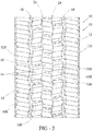
FIG. 2 is a schematic detailed orthogonal view of the tread of the tire ofFIG. 1 . -
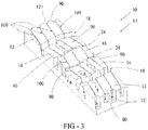
FIG. 3 is a schematic perspective view of part of the tread ofFIG. 2 . -
FIG. 4 is a schematic perspective view of a blade structure for forming part of the tread ofFIGS. 1 through 3 . -
FIG. 5 is a schematic section view taken along line 5-5 inFIG. 3 . -
FIG. 6 is a schematic section view taken along line 6-6 inFIG. 3 . - A pneumatic, or non-pneumatic,
tire 10 is illustrated inFIGS. 1 through 3 and has atread 11. Preferably, thetread 11 has a centercircumferential rib 16, two intermediatecircumferential ribs 14, and twoshoulder ribs 12. These fiveribs shoulder grooves 18 and two centralcircumferential grooves 24. - The two central
circumferential grooves 24 preferably each have a jagged, or zigzag, cross-section with radially vertical walls and a flat bottom (FIGS. 2 and3 ). The twoshoulder grooves 18 are preferably axially wider than the centralcircumferential grooves 24 and preferably each have a jagged, or zigzag, cross-section with slanted walls and a flat bottom (FIGS. 2 and3 ). This design of thegrooves tire tread 11 and to reduce irregular wear and stress across thetread 11. - At least one, several or all of the
ribs sipes 100. Preferably, thesipes 100 in at least one, several of all of theribs sipes 100 in one of the ribs are inclined in an opposite direction versus the axial direction than thesipes 100 in the adjacent rib or ribs, making for instance in case of fiveribs shoulder rib 12 angles of -10º/+10º/-10º/+10º/-10º or of +10º/-10º/+10º/-10º/+10º, or angles of +15º/- 10º/+10º/-10º/+15º or -15º/+10º/-10º/+10º/-15º. Depending on the number of ribs, the angles may be each independently selected from a range of from -20º to +20º. - Each of the
sipes 100 extends in a zigzag manner both as the sipes extend axially across the ribs (FIG. 6 ) and radially inward from the tread surface (FIG. 5 ). Preferably, each of thesipes 100 extends axially fully across therespective rib sipes 100 extends in the radial direction from the radially outermost surface of thetread 11 to a radial depth corresponding to 70 to 110 percent, more preferably 90 to 105 percent or 100 percent, of the maximum radial depth of thecircumferential grooves tread 11. The radially extending zigzag pattern of a given sipe 100 (visible when cutting thetread 11 along the equatorial plane of thetire 10 or parallel to this plane through arespective rib FIG. 4 ) preferably comprises from 2 to 5, more preferably 2 or 3, peaks in the radial zigzag pattern and accordingly from 1 to 6, more preferably 2 or 3, valleys in the radial zigzag pattern (knowing that peaks and valleys alternate and that the terms "peak" and "valley" may be used interchangeably when changing radial viewing direction). - The
multiplanar sipes 100 preferably have a curved, cylindrical or rain drop shaped radially innermost end or surface to mitigate cracking and to increase circumferential flexibility of the tread 11 (FIGS. 5 and 6 ).FIG. 4 shows anexample blade 200 for molding/shaping one of thesipes 100. Theblade 200 demonstrates how the varying zigzag surfaces blend into each other, as well as a corresponding radially innermost cylindrical or rain drop shapedprotrusion 201 for forming the surfaces of thesipes 100. - The "double corrugation" or multiplanar configuration created by the zigzag directions in two planes (axially and radially) of the
sipes 100 of the present invention creates a locking effect of the side surfaces 103 of the sipes thereby improving stiffness of associatedblocks 90 of theribs sipes 100. - As shown in
FIGS. 1 through 3 , thesipes 100 of theshoulder ribs 12 preferably terminate atradial notches 121 in outer lateral surfaces of thetread 11.
Claims (15)
- A tread for a tire (10) comprising, the tread (11) comprising a plurality of circumferential ribs (12, 14, 16), at least one, several or all of the ribs (12, 14, 16) having sipes (100) extending in a zigzag manner as the sipes extend axially across the respective rib (12, 14, 16) and also extending in a zigzag manner as the sipes (100) extend radially inward from a radially outer surface of the respective rib (12, 14, 16).
- The tread as set forth in claim 1 wherein the sipes (100) further include a curved, cylindrical or rain drop shaped radially innermost part (201) or surface.
- The tread as set forth in claim 1 or 2 wherein the plurality of ribs (12, 14, 16) includes a first, circumferential central rib (16), a second, circumferential intermediate rib (14), a third, circumferential intermediate rib (14), a fourth, circumferential shoulder rib (12) and a fifth circumferential shoulder rib (12).
- The tread as set forth in claim 3 wherein only the fourth and fifth ribs (12) have the sipes (100) or wherein only the first rib (16) has the sipes (100).
- The tread as set forth in claim 3 wherein only the second and third ribs (14) have the sipes (100).
- The tread as set forth in claim 3 wherein only the first and fifth ribs (16, 12) or only the first, fourth and fifth ribs (16, 12) have the sipes (100).
- The tread as set forth in claim 3 wherein each of the first, second, third, fourth and fifth ribs (16, 14, 12) have the sipes (100).
- The tread as set forth in claim 3 wherein only the first and second ribs (16, 14) or only the first, second and third ribs (16, 14) have the sipes (100).
- The tread as set forth in at least one of the claims wherein sipes (100) of the fourth and fifth ribs (12) terminate in notches (121) or the sipes (100) in shoulder ribs of the tread (11) terminate in notches (121).
- The tread as set forth in at least one of the claims wherein the sipes (100) in at least one, several of all of the ribs (12, 14, 16) are inclined or slanted in top view onto the tread versus the axial direction preferably making an angle with the axial direction in a range of from -20º to +20º.
- The tread of claim 11 wherein the sipes (100) in one of the ribs (12, 14, 16) are inclined in an opposite direction versus the axial direction than the sipes (100) in the adjacent rib or ribs (12, 14, 16).
- The tread as set forth in at least one of the claims wherein each of the sipes (100) extends axially fully across the respective rib (12, 14, 16).
- The tread as set forth in at least one of the claims wherein the axially extending zigzag pattern of a sipe (100) comprises from 2 to 6, preferably 3 to 5, peaks in the axial zigzag pattern and from 1 to 7, more preferably to 2 to 5, valleys in the axial zigzag pattern; and/or wherein the radially extending zigzag pattern of a sipe (100) comprises from 2 to 5, preferably 2 or 3, peaks in the radial zigzag pattern and from 1 to 6, preferably 2 or 3, valleys in the radial zigzag pattern.
- The tread as set forth in at least one of the claims wherein the sipes (100) extend in the radial direction from the radially outermost surface of the tread (11) to a radial depth corresponding to 70 to 110 percent, more preferably 90 to 105 percent or 100 percent, of the non-skid depth or the maximum radial depth of the circumferential grooves (18, 24).
- A tire, preferably a pneumatic tire (10), having a tread (11) in accordance with at least one of the previous claims.
Applications Claiming Priority (1)
| Application Number | Priority Date | Filing Date | Title |
|---|---|---|---|
| US16/007,148 US20190381837A1 (en) | 2018-06-13 | 2018-06-13 | Multiplane interlocking structure for a tread of a tire |
Publications (2)
| Publication Number | Publication Date |
|---|---|
| EP3581402A1 true EP3581402A1 (en) | 2019-12-18 |
| EP3581402B1 EP3581402B1 (en) | 2021-03-03 |
Family
ID=66776188
Family Applications (1)
| Application Number | Title | Priority Date | Filing Date |
|---|---|---|---|
| EP19178691.2A Active EP3581402B1 (en) | 2018-06-13 | 2019-06-06 | Multiplane interlocking structure for a tread of a tire |
Country Status (2)
| Country | Link |
|---|---|
| US (1) | US20190381837A1 (en) |
| EP (1) | EP3581402B1 (en) |
Families Citing this family (5)
| Publication number | Priority date | Publication date | Assignee | Title |
|---|---|---|---|---|
| DE102019217819A1 (en) * | 2019-11-19 | 2021-05-20 | Continental Reifen Deutschland Gmbh | Pneumatic vehicle tires |
| EP4351885A1 (en) * | 2021-06-10 | 2024-04-17 | Compagnie Generale Des Etablissements Michelin | Tire sipe design with variable teardrop size having larger lateral midpoint |
| US20250050689A1 (en) * | 2021-12-06 | 2025-02-13 | Bridgestone Americas Tire Operations, Llc | Bi-directional interlocking sipe and slot combination |
| CN115674954B (en) * | 2022-08-26 | 2024-10-25 | 大陆马牌轮胎(中国)有限公司 | Wear-resistant tyre |
| JP2024076120A (en) * | 2022-11-24 | 2024-06-05 | 住友ゴム工業株式会社 | tire |
Citations (4)
| Publication number | Priority date | Publication date | Assignee | Title |
|---|---|---|---|---|
| US20150053320A1 (en) * | 2013-08-20 | 2015-02-26 | The Goodyear Tire & Rubber Company | Pneumatic tire tread with sipes and mold blade |
| EP2857225A1 (en) * | 2012-06-05 | 2015-04-08 | The Yokohama Rubber Co., Ltd. | Pneumatic tire |
| DE102013221565A1 (en) * | 2013-10-23 | 2015-04-23 | Continental Reifen Deutschland Gmbh | Vehicle tires |
| US20170066290A1 (en) * | 2015-09-08 | 2017-03-09 | Toyo Tire & Rubber Co., Ltd. | Pneumatic tire |
-
2018
- 2018-06-13 US US16/007,148 patent/US20190381837A1/en not_active Abandoned
-
2019
- 2019-06-06 EP EP19178691.2A patent/EP3581402B1/en active Active
Patent Citations (4)
| Publication number | Priority date | Publication date | Assignee | Title |
|---|---|---|---|---|
| EP2857225A1 (en) * | 2012-06-05 | 2015-04-08 | The Yokohama Rubber Co., Ltd. | Pneumatic tire |
| US20150053320A1 (en) * | 2013-08-20 | 2015-02-26 | The Goodyear Tire & Rubber Company | Pneumatic tire tread with sipes and mold blade |
| DE102013221565A1 (en) * | 2013-10-23 | 2015-04-23 | Continental Reifen Deutschland Gmbh | Vehicle tires |
| US20170066290A1 (en) * | 2015-09-08 | 2017-03-09 | Toyo Tire & Rubber Co., Ltd. | Pneumatic tire |
Also Published As
| Publication number | Publication date |
|---|---|
| EP3581402B1 (en) | 2021-03-03 |
| US20190381837A1 (en) | 2019-12-19 |
Similar Documents
| Publication | Publication Date | Title |
|---|---|---|
| EP3581402B1 (en) | Multiplane interlocking structure for a tread of a tire | |
| US5012847A (en) | Pneumatic tire having tread pattern with reduced stone biting | |
| EP1935671B1 (en) | Pneumatic tire | |
| JP5922364B2 (en) | Reinforced tire tread | |
| EP1987965B1 (en) | Pneumatic tire | |
| EP3492283B1 (en) | Tire tread comprising a stabilizer structure | |
| US9073390B2 (en) | Heavy duty tire | |
| US20110048598A1 (en) | Pneumatic tire | |
| JP7298335B2 (en) | pneumatic tire | |
| EP3444129A1 (en) | Pneumatic tire | |
| JP2017226368A (en) | Pneumatic tire | |
| US11964512B2 (en) | Utility vehicle tire | |
| US20200031171A1 (en) | Pneumatic tire | |
| CN109414962B (en) | Pneumatic tire for vehicle | |
| EP3444128A1 (en) | Tire tread for off the road tires | |
| CN108819621B (en) | Pneumatic tire for automobile | |
| JP7211014B2 (en) | pneumatic tire | |
| EP3670208A1 (en) | Winter tire tread | |
| EP3970994B1 (en) | Tire tread and tire with such a tread | |
| US4479525A (en) | Pneumatic tire tread | |
| US20080066841A1 (en) | Pneumatic tire with tie bars | |
| CN112969598A (en) | Pneumatic tire | |
| EP3970993B1 (en) | Tire tread and tire comprising a stabilizer structure | |
| CN113015633A (en) | Pneumatic tire | |
| JP7650690B2 (en) | Pneumatic tires |
Legal Events
| Date | Code | Title | Description |
|---|---|---|---|
| PUAI | Public reference made under article 153(3) epc to a published international application that has entered the european phase |
Free format text: ORIGINAL CODE: 0009012 |
|
| STAA | Information on the status of an ep patent application or granted ep patent |
Free format text: STATUS: THE APPLICATION HAS BEEN PUBLISHED |
|
| AK | Designated contracting states |
Kind code of ref document: A1 Designated state(s): AL AT BE BG CH CY CZ DE DK EE ES FI FR GB GR HR HU IE IS IT LI LT LU LV MC MK MT NL NO PL PT RO RS SE SI SK SM TR |
|
| AX | Request for extension of the european patent |
Extension state: BA ME |
|
| STAA | Information on the status of an ep patent application or granted ep patent |
Free format text: STATUS: REQUEST FOR EXAMINATION WAS MADE |
|
| 17P | Request for examination filed |
Effective date: 20200618 |
|
| RBV | Designated contracting states (corrected) |
Designated state(s): AL AT BE BG CH CY CZ DE DK EE ES FI FR GB GR HR HU IE IS IT LI LT LU LV MC MK MT NL NO PL PT RO RS SE SI SK SM TR |
|
| RIC1 | Information provided on ipc code assigned before grant |
Ipc: B60C 11/12 20060101ALI20200817BHEP Ipc: B60C 11/03 20060101ALI20200817BHEP Ipc: B60C 11/04 20060101AFI20200817BHEP |
|
| GRAP | Despatch of communication of intention to grant a patent |
Free format text: ORIGINAL CODE: EPIDOSNIGR1 |
|
| STAA | Information on the status of an ep patent application or granted ep patent |
Free format text: STATUS: GRANT OF PATENT IS INTENDED |
|
| INTG | Intention to grant announced |
Effective date: 20200929 |
|
| GRAS | Grant fee paid |
Free format text: ORIGINAL CODE: EPIDOSNIGR3 |
|
| GRAA | (expected) grant |
Free format text: ORIGINAL CODE: 0009210 |
|
| STAA | Information on the status of an ep patent application or granted ep patent |
Free format text: STATUS: THE PATENT HAS BEEN GRANTED |
|
| AK | Designated contracting states |
Kind code of ref document: B1 Designated state(s): AL AT BE BG CH CY CZ DE DK EE ES FI FR GB GR HR HU IE IS IT LI LT LU LV MC MK MT NL NO PL PT RO RS SE SI SK SM TR |
|
| REG | Reference to a national code |
Ref country code: GB Ref legal event code: FG4D |
|
| REG | Reference to a national code |
Ref country code: CH Ref legal event code: EP Ref country code: AT Ref legal event code: REF Ref document number: 1366810 Country of ref document: AT Kind code of ref document: T Effective date: 20210315 |
|
| REG | Reference to a national code |
Ref country code: DE Ref legal event code: R096 Ref document number: 602019002898 Country of ref document: DE |
|
| REG | Reference to a national code |
Ref country code: IE Ref legal event code: FG4D |
|
| REG | Reference to a national code |
Ref country code: LT Ref legal event code: MG9D |
|
| PG25 | Lapsed in a contracting state [announced via postgrant information from national office to epo] |
Ref country code: BG Free format text: LAPSE BECAUSE OF FAILURE TO SUBMIT A TRANSLATION OF THE DESCRIPTION OR TO PAY THE FEE WITHIN THE PRESCRIBED TIME-LIMIT Effective date: 20210603 Ref country code: HR Free format text: LAPSE BECAUSE OF FAILURE TO SUBMIT A TRANSLATION OF THE DESCRIPTION OR TO PAY THE FEE WITHIN THE PRESCRIBED TIME-LIMIT Effective date: 20210303 Ref country code: GR Free format text: LAPSE BECAUSE OF FAILURE TO SUBMIT A TRANSLATION OF THE DESCRIPTION OR TO PAY THE FEE WITHIN THE PRESCRIBED TIME-LIMIT Effective date: 20210604 Ref country code: FI Free format text: LAPSE BECAUSE OF FAILURE TO SUBMIT A TRANSLATION OF THE DESCRIPTION OR TO PAY THE FEE WITHIN THE PRESCRIBED TIME-LIMIT Effective date: 20210303 Ref country code: LT Free format text: LAPSE BECAUSE OF FAILURE TO SUBMIT A TRANSLATION OF THE DESCRIPTION OR TO PAY THE FEE WITHIN THE PRESCRIBED TIME-LIMIT Effective date: 20210303 Ref country code: NO Free format text: LAPSE BECAUSE OF FAILURE TO SUBMIT A TRANSLATION OF THE DESCRIPTION OR TO PAY THE FEE WITHIN THE PRESCRIBED TIME-LIMIT Effective date: 20210603 |
|
| REG | Reference to a national code |
Ref country code: NL Ref legal event code: MP Effective date: 20210303 |
|
| REG | Reference to a national code |
Ref country code: AT Ref legal event code: MK05 Ref document number: 1366810 Country of ref document: AT Kind code of ref document: T Effective date: 20210303 |
|
| PG25 | Lapsed in a contracting state [announced via postgrant information from national office to epo] |
Ref country code: LV Free format text: LAPSE BECAUSE OF FAILURE TO SUBMIT A TRANSLATION OF THE DESCRIPTION OR TO PAY THE FEE WITHIN THE PRESCRIBED TIME-LIMIT Effective date: 20210303 Ref country code: PL Free format text: LAPSE BECAUSE OF FAILURE TO SUBMIT A TRANSLATION OF THE DESCRIPTION OR TO PAY THE FEE WITHIN THE PRESCRIBED TIME-LIMIT Effective date: 20210303 Ref country code: RS Free format text: LAPSE BECAUSE OF FAILURE TO SUBMIT A TRANSLATION OF THE DESCRIPTION OR TO PAY THE FEE WITHIN THE PRESCRIBED TIME-LIMIT Effective date: 20210303 Ref country code: SE Free format text: LAPSE BECAUSE OF FAILURE TO SUBMIT A TRANSLATION OF THE DESCRIPTION OR TO PAY THE FEE WITHIN THE PRESCRIBED TIME-LIMIT Effective date: 20210303 |
|
| PG25 | Lapsed in a contracting state [announced via postgrant information from national office to epo] |
Ref country code: NL Free format text: LAPSE BECAUSE OF FAILURE TO SUBMIT A TRANSLATION OF THE DESCRIPTION OR TO PAY THE FEE WITHIN THE PRESCRIBED TIME-LIMIT Effective date: 20210303 |
|
| PG25 | Lapsed in a contracting state [announced via postgrant information from national office to epo] |
Ref country code: SM Free format text: LAPSE BECAUSE OF FAILURE TO SUBMIT A TRANSLATION OF THE DESCRIPTION OR TO PAY THE FEE WITHIN THE PRESCRIBED TIME-LIMIT Effective date: 20210303 Ref country code: AT Free format text: LAPSE BECAUSE OF FAILURE TO SUBMIT A TRANSLATION OF THE DESCRIPTION OR TO PAY THE FEE WITHIN THE PRESCRIBED TIME-LIMIT Effective date: 20210303 Ref country code: EE Free format text: LAPSE BECAUSE OF FAILURE TO SUBMIT A TRANSLATION OF THE DESCRIPTION OR TO PAY THE FEE WITHIN THE PRESCRIBED TIME-LIMIT Effective date: 20210303 Ref country code: CZ Free format text: LAPSE BECAUSE OF FAILURE TO SUBMIT A TRANSLATION OF THE DESCRIPTION OR TO PAY THE FEE WITHIN THE PRESCRIBED TIME-LIMIT Effective date: 20210303 |
|
| PG25 | Lapsed in a contracting state [announced via postgrant information from national office to epo] |
Ref country code: IS Free format text: LAPSE BECAUSE OF FAILURE TO SUBMIT A TRANSLATION OF THE DESCRIPTION OR TO PAY THE FEE WITHIN THE PRESCRIBED TIME-LIMIT Effective date: 20210703 Ref country code: SK Free format text: LAPSE BECAUSE OF FAILURE TO SUBMIT A TRANSLATION OF THE DESCRIPTION OR TO PAY THE FEE WITHIN THE PRESCRIBED TIME-LIMIT Effective date: 20210303 Ref country code: RO Free format text: LAPSE BECAUSE OF FAILURE TO SUBMIT A TRANSLATION OF THE DESCRIPTION OR TO PAY THE FEE WITHIN THE PRESCRIBED TIME-LIMIT Effective date: 20210303 Ref country code: PT Free format text: LAPSE BECAUSE OF FAILURE TO SUBMIT A TRANSLATION OF THE DESCRIPTION OR TO PAY THE FEE WITHIN THE PRESCRIBED TIME-LIMIT Effective date: 20210705 |
|
| REG | Reference to a national code |
Ref country code: DE Ref legal event code: R097 Ref document number: 602019002898 Country of ref document: DE |
|
| PLBE | No opposition filed within time limit |
Free format text: ORIGINAL CODE: 0009261 |
|
| STAA | Information on the status of an ep patent application or granted ep patent |
Free format text: STATUS: NO OPPOSITION FILED WITHIN TIME LIMIT |
|
| PG25 | Lapsed in a contracting state [announced via postgrant information from national office to epo] |
Ref country code: ES Free format text: LAPSE BECAUSE OF FAILURE TO SUBMIT A TRANSLATION OF THE DESCRIPTION OR TO PAY THE FEE WITHIN THE PRESCRIBED TIME-LIMIT Effective date: 20210303 Ref country code: MC Free format text: LAPSE BECAUSE OF FAILURE TO SUBMIT A TRANSLATION OF THE DESCRIPTION OR TO PAY THE FEE WITHIN THE PRESCRIBED TIME-LIMIT Effective date: 20210303 Ref country code: AL Free format text: LAPSE BECAUSE OF FAILURE TO SUBMIT A TRANSLATION OF THE DESCRIPTION OR TO PAY THE FEE WITHIN THE PRESCRIBED TIME-LIMIT Effective date: 20210303 Ref country code: DK Free format text: LAPSE BECAUSE OF FAILURE TO SUBMIT A TRANSLATION OF THE DESCRIPTION OR TO PAY THE FEE WITHIN THE PRESCRIBED TIME-LIMIT Effective date: 20210303 |
|
| 26N | No opposition filed |
Effective date: 20211206 |
|
| PG25 | Lapsed in a contracting state [announced via postgrant information from national office to epo] |
Ref country code: SI Free format text: LAPSE BECAUSE OF FAILURE TO SUBMIT A TRANSLATION OF THE DESCRIPTION OR TO PAY THE FEE WITHIN THE PRESCRIBED TIME-LIMIT Effective date: 20210303 |
|
| REG | Reference to a national code |
Ref country code: BE Ref legal event code: MM Effective date: 20210630 |
|
| PG25 | Lapsed in a contracting state [announced via postgrant information from national office to epo] |
Ref country code: LU Free format text: LAPSE BECAUSE OF NON-PAYMENT OF DUE FEES Effective date: 20210606 |
|
| PG25 | Lapsed in a contracting state [announced via postgrant information from national office to epo] |
Ref country code: IE Free format text: LAPSE BECAUSE OF NON-PAYMENT OF DUE FEES Effective date: 20210606 |
|
| PG25 | Lapsed in a contracting state [announced via postgrant information from national office to epo] |
Ref country code: IS Free format text: LAPSE BECAUSE OF FAILURE TO SUBMIT A TRANSLATION OF THE DESCRIPTION OR TO PAY THE FEE WITHIN THE PRESCRIBED TIME-LIMIT Effective date: 20210703 |
|
| PG25 | Lapsed in a contracting state [announced via postgrant information from national office to epo] |
Ref country code: BE Free format text: LAPSE BECAUSE OF NON-PAYMENT OF DUE FEES Effective date: 20210630 |
|
| REG | Reference to a national code |
Ref country code: CH Ref legal event code: PL |
|
| PG25 | Lapsed in a contracting state [announced via postgrant information from national office to epo] |
Ref country code: LI Free format text: LAPSE BECAUSE OF NON-PAYMENT OF DUE FEES Effective date: 20220630 Ref country code: CH Free format text: LAPSE BECAUSE OF NON-PAYMENT OF DUE FEES Effective date: 20220630 |
|
| PG25 | Lapsed in a contracting state [announced via postgrant information from national office to epo] |
Ref country code: CY Free format text: LAPSE BECAUSE OF FAILURE TO SUBMIT A TRANSLATION OF THE DESCRIPTION OR TO PAY THE FEE WITHIN THE PRESCRIBED TIME-LIMIT Effective date: 20210303 |
|
| PG25 | Lapsed in a contracting state [announced via postgrant information from national office to epo] |
Ref country code: HU Free format text: LAPSE BECAUSE OF FAILURE TO SUBMIT A TRANSLATION OF THE DESCRIPTION OR TO PAY THE FEE WITHIN THE PRESCRIBED TIME-LIMIT; INVALID AB INITIO Effective date: 20190606 |
|
| GBPC | Gb: european patent ceased through non-payment of renewal fee |
Effective date: 20230606 |
|
| PG25 | Lapsed in a contracting state [announced via postgrant information from national office to epo] |
Ref country code: MK Free format text: LAPSE BECAUSE OF FAILURE TO SUBMIT A TRANSLATION OF THE DESCRIPTION OR TO PAY THE FEE WITHIN THE PRESCRIBED TIME-LIMIT Effective date: 20210303 Ref country code: GB Free format text: LAPSE BECAUSE OF NON-PAYMENT OF DUE FEES Effective date: 20230606 |
|
| PG25 | Lapsed in a contracting state [announced via postgrant information from national office to epo] |
Ref country code: MT Free format text: LAPSE BECAUSE OF FAILURE TO SUBMIT A TRANSLATION OF THE DESCRIPTION OR TO PAY THE FEE WITHIN THE PRESCRIBED TIME-LIMIT Effective date: 20210303 |
|
| PGFP | Annual fee paid to national office [announced via postgrant information from national office to epo] |
Ref country code: DE Payment date: 20250520 Year of fee payment: 7 |
|
| PGFP | Annual fee paid to national office [announced via postgrant information from national office to epo] |
Ref country code: IT Payment date: 20250520 Year of fee payment: 7 |
|
| PGFP | Annual fee paid to national office [announced via postgrant information from national office to epo] |
Ref country code: FR Payment date: 20250520 Year of fee payment: 7 |
|
| PGFP | Annual fee paid to national office [announced via postgrant information from national office to epo] |
Ref country code: TR Payment date: 20250527 Year of fee payment: 7 |