EP3581401A1 - Construction vehicle tire - Google Patents
Construction vehicle tire Download PDFInfo
- Publication number
- EP3581401A1 EP3581401A1 EP18751985.5A EP18751985A EP3581401A1 EP 3581401 A1 EP3581401 A1 EP 3581401A1 EP 18751985 A EP18751985 A EP 18751985A EP 3581401 A1 EP3581401 A1 EP 3581401A1
- Authority
- EP
- European Patent Office
- Prior art keywords
- width direction
- groove
- tire
- narrow groove
- tread
- Prior art date
- Legal status (The legal status is an assumption and is not a legal conclusion. Google has not performed a legal analysis and makes no representation as to the accuracy of the status listed.)
- Granted
Links
Images


Classifications
-
- B—PERFORMING OPERATIONS; TRANSPORTING
- B60—VEHICLES IN GENERAL
- B60C—VEHICLE TYRES; TYRE INFLATION; TYRE CHANGING; CONNECTING VALVES TO INFLATABLE ELASTIC BODIES IN GENERAL; DEVICES OR ARRANGEMENTS RELATED TO TYRES
- B60C11/00—Tyre tread bands; Tread patterns; Anti-skid inserts
- B60C11/03—Tread patterns
- B60C11/0311—Patterns comprising tread lugs arranged parallel or oblique to the axis of rotation
-
- B—PERFORMING OPERATIONS; TRANSPORTING
- B60—VEHICLES IN GENERAL
- B60C—VEHICLE TYRES; TYRE INFLATION; TYRE CHANGING; CONNECTING VALVES TO INFLATABLE ELASTIC BODIES IN GENERAL; DEVICES OR ARRANGEMENTS RELATED TO TYRES
- B60C11/00—Tyre tread bands; Tread patterns; Anti-skid inserts
- B60C11/03—Tread patterns
- B60C11/13—Tread patterns characterised by the groove cross-section, e.g. for buttressing or preventing stone-trapping
- B60C11/1307—Tread patterns characterised by the groove cross-section, e.g. for buttressing or preventing stone-trapping with special features of the groove walls
-
- B—PERFORMING OPERATIONS; TRANSPORTING
- B60—VEHICLES IN GENERAL
- B60C—VEHICLE TYRES; TYRE INFLATION; TYRE CHANGING; CONNECTING VALVES TO INFLATABLE ELASTIC BODIES IN GENERAL; DEVICES OR ARRANGEMENTS RELATED TO TYRES
- B60C11/00—Tyre tread bands; Tread patterns; Anti-skid inserts
-
- B—PERFORMING OPERATIONS; TRANSPORTING
- B60—VEHICLES IN GENERAL
- B60C—VEHICLE TYRES; TYRE INFLATION; TYRE CHANGING; CONNECTING VALVES TO INFLATABLE ELASTIC BODIES IN GENERAL; DEVICES OR ARRANGEMENTS RELATED TO TYRES
- B60C11/00—Tyre tread bands; Tread patterns; Anti-skid inserts
- B60C11/03—Tread patterns
-
- B—PERFORMING OPERATIONS; TRANSPORTING
- B60—VEHICLES IN GENERAL
- B60C—VEHICLE TYRES; TYRE INFLATION; TYRE CHANGING; CONNECTING VALVES TO INFLATABLE ELASTIC BODIES IN GENERAL; DEVICES OR ARRANGEMENTS RELATED TO TYRES
- B60C11/00—Tyre tread bands; Tread patterns; Anti-skid inserts
- B60C11/03—Tread patterns
- B60C11/13—Tread patterns characterised by the groove cross-section, e.g. for buttressing or preventing stone-trapping
- B60C11/1376—Three dimensional block surfaces departing from the enveloping tread contour
- B60C11/1392—Three dimensional block surfaces departing from the enveloping tread contour with chamfered block edges
-
- B—PERFORMING OPERATIONS; TRANSPORTING
- B60—VEHICLES IN GENERAL
- B60C—VEHICLE TYRES; TYRE INFLATION; TYRE CHANGING; CONNECTING VALVES TO INFLATABLE ELASTIC BODIES IN GENERAL; DEVICES OR ARRANGEMENTS RELATED TO TYRES
- B60C11/00—Tyre tread bands; Tread patterns; Anti-skid inserts
- B60C11/03—Tread patterns
- B60C2011/0337—Tread patterns characterised by particular design features of the pattern
- B60C2011/0339—Grooves
- B60C2011/0341—Circumferential grooves
- B60C2011/0344—Circumferential grooves provided at the equatorial plane
-
- B—PERFORMING OPERATIONS; TRANSPORTING
- B60—VEHICLES IN GENERAL
- B60C—VEHICLE TYRES; TYRE INFLATION; TYRE CHANGING; CONNECTING VALVES TO INFLATABLE ELASTIC BODIES IN GENERAL; DEVICES OR ARRANGEMENTS RELATED TO TYRES
- B60C11/00—Tyre tread bands; Tread patterns; Anti-skid inserts
- B60C11/03—Tread patterns
- B60C2011/0337—Tread patterns characterised by particular design features of the pattern
- B60C2011/0339—Grooves
- B60C2011/0341—Circumferential grooves
- B60C2011/0348—Narrow grooves, i.e. having a width of less than 4 mm
-
- B—PERFORMING OPERATIONS; TRANSPORTING
- B60—VEHICLES IN GENERAL
- B60C—VEHICLE TYRES; TYRE INFLATION; TYRE CHANGING; CONNECTING VALVES TO INFLATABLE ELASTIC BODIES IN GENERAL; DEVICES OR ARRANGEMENTS RELATED TO TYRES
- B60C11/00—Tyre tread bands; Tread patterns; Anti-skid inserts
- B60C11/03—Tread patterns
- B60C2011/0337—Tread patterns characterised by particular design features of the pattern
- B60C2011/0339—Grooves
- B60C2011/0358—Lateral grooves, i.e. having an angle of 45 to 90 degees to the equatorial plane
- B60C2011/036—Narrow grooves, i.e. having a width of less than 3 mm
-
- B—PERFORMING OPERATIONS; TRANSPORTING
- B60—VEHICLES IN GENERAL
- B60C—VEHICLE TYRES; TYRE INFLATION; TYRE CHANGING; CONNECTING VALVES TO INFLATABLE ELASTIC BODIES IN GENERAL; DEVICES OR ARRANGEMENTS RELATED TO TYRES
- B60C11/00—Tyre tread bands; Tread patterns; Anti-skid inserts
- B60C11/03—Tread patterns
- B60C2011/0337—Tread patterns characterised by particular design features of the pattern
- B60C2011/0339—Grooves
- B60C2011/0381—Blind or isolated grooves
-
- B—PERFORMING OPERATIONS; TRANSPORTING
- B60—VEHICLES IN GENERAL
- B60C—VEHICLE TYRES; TYRE INFLATION; TYRE CHANGING; CONNECTING VALVES TO INFLATABLE ELASTIC BODIES IN GENERAL; DEVICES OR ARRANGEMENTS RELATED TO TYRES
- B60C11/00—Tyre tread bands; Tread patterns; Anti-skid inserts
- B60C11/03—Tread patterns
- B60C11/13—Tread patterns characterised by the groove cross-section, e.g. for buttressing or preventing stone-trapping
- B60C11/1307—Tread patterns characterised by the groove cross-section, e.g. for buttressing or preventing stone-trapping with special features of the groove walls
- B60C2011/133—Tread patterns characterised by the groove cross-section, e.g. for buttressing or preventing stone-trapping with special features of the groove walls comprising recesses
-
- B—PERFORMING OPERATIONS; TRANSPORTING
- B60—VEHICLES IN GENERAL
- B60C—VEHICLE TYRES; TYRE INFLATION; TYRE CHANGING; CONNECTING VALVES TO INFLATABLE ELASTIC BODIES IN GENERAL; DEVICES OR ARRANGEMENTS RELATED TO TYRES
- B60C2200/00—Tyres specially adapted for particular applications
- B60C2200/06—Tyres specially adapted for particular applications for heavy duty vehicles
- B60C2200/065—Tyres specially adapted for particular applications for heavy duty vehicles for construction vehicles
Definitions
- Patent Literature 1 a structure that cools the tread by forming a slope-like notch groove, which is inclined toward an inner side in a tire radial direction, on the tread has been known (for example, Patent Literature 1).
- the temperature increase of the tread can be further suppressed by increasing the number of the slope-like notch grooves described above, however in such a case, other performance (for example, wear resistant performance) might be deteriorated.
- an object of the present invention is, in consideration of the problem described above, to provide a construction vehicle tire capable of cooling a whole of a tread further efficiently while suppressing an influence to other performance.
- a construction vehicle tire (construction vehicle tire 10A) has a tread (tread 20) including a width direction narrow groove (width direction narrow groove 100) extended in a tire width direction, a center circumferential direction groove (circumferential direction groove 30) communicated with the width direction narrow groove and formed at a position including a tire equatorial line, an outer side circumferential direction groove (circumferential direction grooves 40, 50) communicated with the width direction narrow groove and formed at an outer side in the tire width direction with respect to the width direction narrow groove, and a notch groove (notch groove 110) formed in a slope-like shape and communicated with the width direction narrow groove.
- a tread including a width direction narrow groove (width direction narrow groove 100) extended in a tire width direction, a center circumferential direction groove (circumferential direction groove 30) communicated with the width direction narrow groove and formed at a position including a tire equatorial line, an outer side circumferential direction groove (circumferential direction grooves 40, 50) communicated
- a shoulder lug groove (shoulder lug groove 60) is formed on the tread at the outer side in the tire width direction with respect to the width direction narrow groove and communicated with the width direction narrow groove through the outer side circumferential direction groove. Only one notch groove is formed in a predetermined range corresponding to a position far away from the tire equatorial line by a distance of 1/8 of a width of the tread.
- a construction vehicle tire (construction vehicle tire 10B) has a tread (tread 20) including a width direction narrow groove (width direction narrow groove 200) extended in a tire width direction, a center circumferential direction groove (circumferential direction groove 30) communicated with the width direction narrow groove and formed at a position including a tire equatorial line, an outer side circumferential direction groove (circumferential direction grooves 40, 50) communicated with the width direction narrow groove and formed at an outer side in the tire width direction with respect to the width direction narrow groove, and a notch groove (notch grooves 210, 220) formed in a slope-like shape and communicated with the width direction narrow groove.
- a tread including a width direction narrow groove (width direction narrow groove 200) extended in a tire width direction, a center circumferential direction groove (circumferential direction groove 30) communicated with the width direction narrow groove and formed at a position including a tire equatorial line, an outer side circumferential direction groove (circumferential direction grooves 40
- the notch groove is formed in each of a predetermined range corresponding to a position far away from the tire equatorial line by a distance of 1/16 of a width of the tread and a predetermined range corresponding to a position far away from the tire equatorial line by a distance of 1/4 of the width of the tread.
- a construction vehicle tire (construction vehicle tire 10) has a tread (tread 20) including a first width direction narrow groove (width direction narrow groove 100) extended in a tire width direction, a second width direction narrow groove (width direction groove 200) adjacent to the first width direction narrow groove in a tire circumferential direction and extended in the tire width direction, a center circumferential direction groove (circumferential direction groove 30) communicated with the first width direction narrow groove and the second width direction narrow groove and formed at a position including a tire equatorial line, an outer side circumferential direction groove (circumferential direction grooves 40, 50) communicated with the first width direction narrow groove and the second width direction narrow groove and formed at an outer side in the tire width direction with respect to the first width direction narrow groove and the second width direction narrow groove, a first notch groove (notch groove 110) formed in a slope-like shape and communicated with the first width direction narrow groove, and a second notch groove (notch grooves 210, 220) formed in a slope
- a shoulder lug groove (shoulder lug groove 60) is formed on the tread at the outer side in the tire width direction with respect to the first width direction narrow groove and communicated with the first width direction narrow groove through the outer side circumferential direction groove. Only one first notch groove is formed in a predetermined range corresponding to a position far away from the tire equatorial line by a distance of 1/8 of a width of the tread. The second notch groove is formed in each of a predetermined range corresponding to a position far away from the tire equatorial line by a distance of 1/16 of the width of the tread and a predetermined range corresponding to a position far away from the tire equatorial line by a distance of 1/4 of the width of the tread.
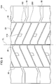
- Fig. 1 is a plane developed view illustrating a part of a construction vehicle tire 10 according to the present embodiment.
- the construction vehicle tire 10 is formed as a pneumatic tire mounted to a dump truck or the like that travels on an uneven ground such as a mine.
- a size of the construction vehicle tire 10 is not especially limited, however a tire of 49, 51, 57, or 63 inches is widely adopted.
- the construction vehicle tire 10 may be also called an ORR (Off-the-Road Radial) tire.
- ORR Off-the-Road Radial
- the construction vehicle tire 10 is not always limited to the radial tire.
- the construction vehicle tire 10 is provided with a tread 20 that contacts a road surface.
- a plurality of circumferential direction grooves 30, 40, 50 extended in a tire circumferential direction is formed on the tread 20.
- a plurality of width direction narrow grooves 100, 200 extended in a tire width direction is formed on the tread.
- the construction vehicle tire 10 has a substantially symmetrical shape with respect to a tire equatorial line CL. However, the width direction grooves 100, 200 at one side and another side with respect to the tire equatorial line CL are slightly shifted to each other in the tire circumferential direction.
- the circumferential direction groove 30 is communicated with the width direction narrow groove 100 and the width direction narrow groove 200.
- the circumferential direction groove 30 is formed at a position including the tire equatorial line CL.
- the circumferential direction groove 30 is served as a center circumferential direction groove.
- the circumferential direction groove 40 is also communicated with the width direction narrow groove 100.
- the circumferential direction groove 40 is formed at an outer side in the tire width direction with respect to the width direction narrow groove 100. Further, the circumferential direction groove 40 is communicated with the width direction narrow groove 200. The circumferential direction groove 40 is formed at an outer side in the tire width direction with respect to the width direction narrow groove 200.
- the circumferential direction groove 50 is formed at a side opposite to the circumferential direction groove 40 with respect to the tire equatorial line CL.
- the circumferential direction groove 50 has a shape similar to that of the circumferential direction groove 40.
- the circumferential direction grooves 40, 50 are served as an outer side circumferential direction groove.
- a configuration at a side of the circumferential direction groove 40 with respect to the tire equatorial line CL is described.
- a shoulder lug groove 60 is formed on the tread 20.
- the shoulder lug groove 60 is formed at the outer side in the tire width direction with respect to the width direction narrow groove 100.
- the shoulder lug groove 60 is communicated with the width direction narrow groove 100 through the circumferential direction groove 40.
- the shoulder lug groove 60 is extended along the tire width direction.
- the width direction narrow groove 100 is formed as a narrow groove extended in the tire width direction.
- the narrow groove denotes a groove having at least a width smaller than a depth of the groove.
- the width direction narrow groove 100 is served as a first width direction narrow groove.
- a width of the width direction narrow groove 100 is approximately 10 mm, and a depth of the width direction narrow groove 100 is approximately 100 mm (in a tire of 63 inches).
- the width and the depth of the groove may be changed as needed in accordance with a size or a specification of the tire. In tires of 49 inches to 63 inches adopted as the construction vehicle tire, the width of the groove is approximately 3 mm to 10 mm, and the depth of the groove is approximately 40 mm to 100 mm. Further, in the present embodiment, the width direction narrow groove 100 is slightly inclined against the tire width direction.
- the width direction narrow groove 200 is also formed as a narrow groove extended in the tire width direction.
- the width direction narrow groove 200 is adjacent to the width direction narrow groove 100 in the tire circumferential direction.
- the width direction narrow groove 200 is served as a second width direction narrow groove.
- a plurality of notch grooves 110, 210, 220 is formed on the tread 20.
- the notch groove 110 is formed in a slope-like shape and communicated with the width direction narrow groove 100.
- each of the notch grooves 110, 210, 220 is formed in a parallelogram-like shape in a tread surface view.
- the notch groove 110 is served as a first notch groove.
- Only one notch groove 110 is formed in a predetermined range corresponding to a position far away from the tire equatorial line CL by a distance of 1/8 of a width of the tread 20 (hereinafter, a tread width).
- the width of the tread 20 denotes a ground contact width of the tread 20 in a state in which a standard load is applied to the construction vehicle tire 10, which is mounted to a standard rim wheel with air filled at standard inner pressure designated by the vehicle.
- the distance is approximately 200 mm (at a center position of the notch groove 110 in the tire width direction), and the width of the notch groove 110 is approximately 50 mm.
- the predetermined range denotes a range of approximately respective notch grooves 110 (namely, approximately ⁇ 50mm).
- Each of the notch grooves 210, 220 is formed in a slope-like shape and communicated with the width direction narrow groove 200.
- the notch grooves 210, 220 are served as a second notch groove.
- Each of the notch grooves 210, 220 has a shape similar to that of the notch groove 110.
- the notch groove 210 is formed in a predetermined range corresponding to a position far away from the tire equatorial line CL by a distance of 1/16 of the tread width.
- the notch groove 220 is formed in a predetermined range corresponding to a position far away from the tire equatorial line CL by a distance of 1/4 of the tread width.
- the distance relating to the notch groove 210 is approximately 100 mm (at a center position of the notch groove 210 in the tire width direction), and the distance relating to the notch groove 220 is approximately 400 mm (at a center position of the notch groove 220 in the tire width direction).
- the predetermined range denotes a range of approximately respective notch grooves 210 (namely, approximately ⁇ 50mm) to respective directions from the center position.
- the predetermined range may further include a position far away from the center position to an inner direction by a distance of approximately two notch grooves 220 (namely, approximately 100 mm).
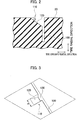
- Fig. 2 is a cross-sectional view along the tire circumferential direction illustrating the width direction narrow groove 100 and the notch groove 110.
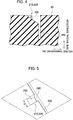
- Fig. 3 is a perspective view illustrating the notch groove 110.
- Fig. 4 is a cross-sectional view along the tire circumferential direction illustrating the width direction narrow groove 200 and the notch grooves 210, 220.
- Fig. 5 is a perspective view illustrating the notch grooves 210, 220.
- the notch groove 110 is communicated with the width direction narrow groove 100.
- the notch groove 110 has a slope portion 120 communicated with the width direction narrow groove 100.
- the slope portion 120 is extended along the tire circumferential direction and inclined to be close to the inner side in the tire radial direction, from the surface of the tread 20 to the width direction narrow groove 100.
- a width W of the slope portion 120 namely a width of the notch groove 100, is approximately 50 mm.
- An incline angle ⁇ of the slope portion 120 against the surface of the tread 20 is approximately 20 degrees.
- the notch groove 110 has the slope portion 120, air flows into the width direction narrow groove 100 through the slope portion 120 when the construction vehicle tire 10 is rolling. Specifically, the air collides with a groove wall 130 of the width direction narrow groove 100 through the slope portion 120 and spreads in the width direction narrow groove 100.
- each of the notch grooves 210, 220 is communicated with the width direction narrow groove 200.
- each of the notch grooves 210, 220 has a slope portion 230 communicated with the width direction narrow groove 200.
- Each of the notch grooves 210, 220 has a shape similar to that of the notch groove 110.
- the slope portion 230 is extended along the tire circumferential direction and inclined to be close to the inner side in the tire radial direction, from the surface of the tread 20 to the width direction narrow groove 200.
- a width W of the slope 230 namely a width of each of the notch grooves 210, 220, is approximately 50 mm.
- An incline angle ⁇ of the slope portion 230 is approximately 20 degrees.
- Table 1 shows a result of an evaluation test of the construction vehicle tire 10 (by FEM).
- Table 1 Temperature decrease of tread (average of respective positions) Result compared to a width direction narrow groove without a notch groove Result compared to a width direction narrow groove with a notch groove (position of 1/4W) Width direction narrow groove 100 2.9 °C 0.9 °C Width direction narrow groove 200 4.3 °C 2.3 °C
- Table 1 shows a temperature decrease of the surface of the tread 20 near each of the width direction narrow groove 100 and the width direction narrow groove 200. A tire specification and a test method are described below.
- the temperature of the tread surface is decreased by 2.9 °C, compared to a width direction narrow groove without a notch groove, and the temperature of the tread surface is decreased by 0.9 °C, compared to a width direction narrow groove with only one notch groove formed at a position of 1/4W.
- the width direction narrow groove 200 namely in a case in which the width direction narrow groove 200 is not communicated with the shoulder lug groove, an end portion of the width direction narrow groove 200 at the outer side in the tire width direction is terminated in a block (land portion) of the tread 20, and the notch grooves (notch grooves 210, 220) are formed in respective predetermined ranges corresponding to positions far away by distances of 1/16 and 1/4 of the tread width (1/16W, 1/4W), the temperature of the tread surface is decreased by 4.9 °C, compared to the width direction narrow groove without the notch groove, and the temperature of the tread surface is decreased by 2.3 °C, compared to the width direction narrow groove with only one notch groove formed at the position of 1/4W.
- the tread 20 in the width direction narrow groove 100, the tread 20 can be cooled efficiently by optimizing the position of the notch groove more than by increasing the number of the notch grooves.
- the tread 20 in the width direction narrow groove 200, the tread 20 can be cooled efficiently by increasing the amount of the air invited into width direction narrow groove 200 by forming the two notch grooves and by optimizing the positions of two notch grooves.
- width direction narrow groove 100 and the width direction narrow groove 200 it is not necessary to form many notch grooves, and therefore there is substantially no influence to other performance such as wear resistant performance.
- the notch grooves are formed in the width direction narrow groove 100 and the width direction narrow groove 200 at respectively optimized positions in accordance with the shapes of the grooves, and thereby the whole of the tread 20 can be cooled further efficiently.
- the temperature increase of the tread 20 can be suppressed by its structure, and thereby rubber superior in the wear resistance can be adopted and as a result the wear resistant performance of the tire can be improved.
- the notch groove 110 has the slope portion 120.
- each of the notch grooves 210, 220 has the slope portion 230.
- Each of the slope portions 120, 230 is inclined to be close to the inner side in the tire radial direction, toward each width direction narrow groove, so that the smooth air flow into each width direction narrow groove can be facilitated. With this, the whole of the tread 20 can be cooled further efficiently.
- Fig. 6 is a plane developed view illustrating a part of a construction vehicle tire 10A according to one modified example. As shown in Fig. 6 , compared to the construction vehicle tire 10, in the construction vehicle tire 10A, only the notch groove 110 is formed, and therefore the notch grooves 210, 220 are not formed.
- Fig. 7 is a plane developed view illustrating a part of a construction vehicle tire 10B according to another modified example. As shown in Fig. 7 , compared to the construction vehicle tire 10, in the construction vehicle tire 10B, only the notch grooves 210, 220 are formed, and therefore the notch groove 110 is not formed.
- the construction vehicle tire 10A and the construction vehicle tire 10B are inferior to the construction vehicle tire 10, but they can also cool the whole of the tread 20 efficiently while suppressing an influence to other performance.
- each of the notch grooves 110, 210, 220 is formed in a parallelogram-like shape in the tread surface view, however the notch groove may not be formed in a parallelogram-like shape.
- a portion corresponding to a side of the notch groove (slope portion) may not be parallel to the groove wall of the width direction narrow groove.
- each of the width direction narrow grooves 100, 200 is slightly inclined against the tire width direction, however the width direction narrow groove may not be inclined against the tire width direction, and therefore the width direction narrow groove may be extended parallel to the tire width direction.
- the shoulder lug groove 60 is extended to the end portion at the outer side in the tire width direction of the tread 20, however the shoulder lug groove 60 may not be extended to the end portion.
- the construction vehicle tire according to the present invention can cool the whole of the tread further efficiently while suppressing the influence to other performance.
Landscapes
- Engineering & Computer Science (AREA)
- Mechanical Engineering (AREA)
- Tires In General (AREA)
Abstract
Description
- In a tire mounted to a dump truck or the like that travels on an uneven ground such as a mine, which is a so-called construction vehicle tire, it is important to suppress a temperature increase of a tread. Thus, a structure that cools the tread by forming a slope-like notch groove, which is inclined toward an inner side in a tire radial direction, on the tread has been known (for example, Patent Literature 1).
- Specifically, air flows into the slope-like notch groove in accordance with rolling of the tire, so that heat exchange at a surface of the tread is facilitated. With this, the temperature increase of the tread can be suppressed.
- [PTL 1] Japanese Patent No.
5719935 - In recent years, it is strongly desired that the construction vehicle tire described above can adapt to a high speed and a large load of a vehicle. Such a desire causes a further temperature increase of the tread.
- The temperature increase of the tread can be further suppressed by increasing the number of the slope-like notch grooves described above, however in such a case, other performance (for example, wear resistant performance) might be deteriorated.
- Accordingly, an object of the present invention is, in consideration of the problem described above, to provide a construction vehicle tire capable of cooling a whole of a tread further efficiently while suppressing an influence to other performance.
- A construction vehicle tire (
construction vehicle tire 10A) according to one aspect of the present invention has a tread (tread 20) including a width direction narrow groove (width direction narrow groove 100) extended in a tire width direction, a center circumferential direction groove (circumferential direction groove 30) communicated with the width direction narrow groove and formed at a position including a tire equatorial line, an outer side circumferential direction groove (circumferential direction grooves 40, 50) communicated with the width direction narrow groove and formed at an outer side in the tire width direction with respect to the width direction narrow groove, and a notch groove (notch groove 110) formed in a slope-like shape and communicated with the width direction narrow groove. A shoulder lug groove (shoulder lug groove 60) is formed on the tread at the outer side in the tire width direction with respect to the width direction narrow groove and communicated with the width direction narrow groove through the outer side circumferential direction groove. Only one notch groove is formed in a predetermined range corresponding to a position far away from the tire equatorial line by a distance of 1/8 of a width of the tread. - A construction vehicle tire (
construction vehicle tire 10B) according to one aspect of the present invention has a tread (tread 20) including a width direction narrow groove (width direction narrow groove 200) extended in a tire width direction, a center circumferential direction groove (circumferential direction groove 30) communicated with the width direction narrow groove and formed at a position including a tire equatorial line, an outer side circumferential direction groove (circumferential direction grooves 40, 50) communicated with the width direction narrow groove and formed at an outer side in the tire width direction with respect to the width direction narrow groove, and a notch groove (notch grooves 210, 220) formed in a slope-like shape and communicated with the width direction narrow groove. The notch groove is formed in each of a predetermined range corresponding to a position far away from the tire equatorial line by a distance of 1/16 of a width of the tread and a predetermined range corresponding to a position far away from the tire equatorial line by a distance of 1/4 of the width of the tread. - A construction vehicle tire (construction vehicle tire 10) according to one aspect of the present invention has a tread (tread 20) including a first width direction narrow groove (width direction narrow groove 100) extended in a tire width direction, a second width direction narrow groove (width direction groove 200) adjacent to the first width direction narrow groove in a tire circumferential direction and extended in the tire width direction, a center circumferential direction groove (circumferential direction groove 30) communicated with the first width direction narrow groove and the second width direction narrow groove and formed at a position including a tire equatorial line, an outer side circumferential direction groove (
circumferential direction grooves 40, 50) communicated with the first width direction narrow groove and the second width direction narrow groove and formed at an outer side in the tire width direction with respect to the first width direction narrow groove and the second width direction narrow groove, a first notch groove (notch groove 110) formed in a slope-like shape and communicated with the first width direction narrow groove, and a second notch groove (notch grooves 210, 220) formed in a slope-like shape and communicated with the second width direction narrow groove. A shoulder lug groove (shoulder lug groove 60) is formed on the tread at the outer side in the tire width direction with respect to the first width direction narrow groove and communicated with the first width direction narrow groove through the outer side circumferential direction groove. Only one first notch groove is formed in a predetermined range corresponding to a position far away from the tire equatorial line by a distance of 1/8 of a width of the tread. The second notch groove is formed in each of a predetermined range corresponding to a position far away from the tire equatorial line by a distance of 1/16 of the width of the tread and a predetermined range corresponding to a position far away from the tire equatorial line by a distance of 1/4 of the width of the tread. -
- [
Fig. 1] Fig. 1 is a plane developed view illustrating a part of aconstruction vehicle tire 10. - [
Fig. 2] Fig. 2 is a cross-sectional view along a tire circumferential direction illustrating a width directionnarrow groove 100 and anotch groove 110. - [
Fig. 3] Fig. 3 is a perspective view illustrating thenotch groove 110. - [
Fig. 4] Fig. 4 is a cross-sectional view along the tire circumferential direction illustrating a width directionnarrow groove 200 andnotch grooves - [
Fig. 5] Fig. 5 is a perspective view illustrating thenotch grooves - [
Fig. 6] Fig. 6 is a plane developed view illustrating a part of aconstruction vehicle tire 10A according to one modified example. - [
Fig. 7] Fig. 7 is a plane developed view illustrating a part of aconstruction vehicle tire 10B according to another modified example. - Hereinafter, an embodiment of the present invention will be described with reference to the drawings. The same reference signs or similar reference signs are assigned to the same functions or the same components and the description thereof is therefore omitted.
-
Fig. 1 is a plane developed view illustrating a part of aconstruction vehicle tire 10 according to the present embodiment. Theconstruction vehicle tire 10 is formed as a pneumatic tire mounted to a dump truck or the like that travels on an uneven ground such as a mine. - A size of the
construction vehicle tire 10 is not especially limited, however a tire of 49, 51, 57, or 63 inches is widely adopted. Theconstruction vehicle tire 10 may be also called an ORR (Off-the-Road Radial) tire. However, theconstruction vehicle tire 10 is not always limited to the radial tire. - As shown in
Fig. 1 , theconstruction vehicle tire 10 is provided with atread 20 that contacts a road surface. A plurality of circumferential direction grooves 30, 40, 50 extended in a tire circumferential direction is formed on thetread 20. Further, a plurality of width directionnarrow grooves - The
construction vehicle tire 10 has a substantially symmetrical shape with respect to a tire equatorial line CL. However, the width direction grooves 100, 200 at one side and another side with respect to the tire equatorial line CL are slightly shifted to each other in the tire circumferential direction. - The
circumferential direction groove 30 is communicated with the width directionnarrow groove 100 and the width directionnarrow groove 200. Thecircumferential direction groove 30 is formed at a position including the tire equatorial line CL. In the present embodiment, thecircumferential direction groove 30 is served as a center circumferential direction groove. - The
circumferential direction groove 40 is also communicated with the width directionnarrow groove 100. Thecircumferential direction groove 40 is formed at an outer side in the tire width direction with respect to the width directionnarrow groove 100. Further, thecircumferential direction groove 40 is communicated with the width directionnarrow groove 200. Thecircumferential direction groove 40 is formed at an outer side in the tire width direction with respect to the width directionnarrow groove 200. - The
circumferential direction groove 50 is formed at a side opposite to thecircumferential direction groove 40 with respect to the tire equatorial line CL. Thecircumferential direction groove 50 has a shape similar to that of thecircumferential direction groove 40. In the resent embodiment, the circumferential direction grooves 40, 50 are served as an outer side circumferential direction groove. Hereinafter, a configuration at a side of thecircumferential direction groove 40 with respect to the tire equatorial line CL is described. - A
shoulder lug groove 60 is formed on thetread 20. Theshoulder lug groove 60 is formed at the outer side in the tire width direction with respect to the width directionnarrow groove 100. Theshoulder lug groove 60 is communicated with the width directionnarrow groove 100 through thecircumferential direction groove 40. Theshoulder lug groove 60 is extended along the tire width direction. - The width direction
narrow groove 100 is formed as a narrow groove extended in the tire width direction. The narrow groove denotes a groove having at least a width smaller than a depth of the groove. In the present embodiment, the width directionnarrow groove 100 is served as a first width direction narrow groove. - In the present embodiment, a width of the width direction
narrow groove 100 is approximately 10 mm, and a depth of the width directionnarrow groove 100 is approximately 100 mm (in a tire of 63 inches). The width and the depth of the groove may be changed as needed in accordance with a size or a specification of the tire. In tires of 49 inches to 63 inches adopted as the construction vehicle tire, the width of the groove is approximately 3 mm to 10 mm, and the depth of the groove is approximately 40 mm to 100 mm. Further, in the present embodiment, the width directionnarrow groove 100 is slightly inclined against the tire width direction. - The width direction
narrow groove 200 is also formed as a narrow groove extended in the tire width direction. The width directionnarrow groove 200 is adjacent to the width directionnarrow groove 100 in the tire circumferential direction. In the present embodiment, the width directionnarrow groove 200 is served as a second width direction narrow groove. - A plurality of
notch grooves tread 20. Thenotch groove 110 is formed in a slope-like shape and communicated with the width directionnarrow groove 100. As shown inFig. 1 , each of thenotch grooves notch groove 110 is served as a first notch groove. - Only one
notch groove 110 is formed in a predetermined range corresponding to a position far away from the tire equatorial line CL by a distance of 1/8 of a width of the tread 20 (hereinafter, a tread width). The width of thetread 20 denotes a ground contact width of thetread 20 in a state in which a standard load is applied to theconstruction vehicle tire 10, which is mounted to a standard rim wheel with air filled at standard inner pressure designated by the vehicle. - In the present embodiment, the distance is approximately 200 mm (at a center position of the
notch groove 110 in the tire width direction), and the width of thenotch groove 110 is approximately 50 mm. The predetermined range denotes a range of approximately respective notch grooves 110 (namely, approximately ± 50mm). - Each of the
notch grooves narrow groove 200. In the present embodiment, thenotch grooves notch grooves notch groove 110. - The
notch groove 210 is formed in a predetermined range corresponding to a position far away from the tire equatorial line CL by a distance of 1/16 of the tread width. Thenotch groove 220 is formed in a predetermined range corresponding to a position far away from the tire equatorial line CL by a distance of 1/4 of the tread width. - In the present embodiment, the distance relating to the
notch groove 210 is approximately 100 mm (at a center position of thenotch groove 210 in the tire width direction), and the distance relating to thenotch groove 220 is approximately 400 mm (at a center position of thenotch groove 220 in the tire width direction). - Regarding the
notch groove 210, the predetermined range denotes a range of approximately respective notch grooves 210 (namely, approximately ± 50mm) to respective directions from the center position. On the other hand, regarding thenotch groove 220, since thenotch groove 220 is located at the outer side in the tire width direction and is closer to thecircumferential direction groove 40, the predetermined range may further include a position far away from the center position to an inner direction by a distance of approximately two notch grooves 220 (namely, approximately 100 mm). -
Fig. 2 is a cross-sectional view along the tire circumferential direction illustrating the width directionnarrow groove 100 and thenotch groove 110.Fig. 3 is a perspective view illustrating thenotch groove 110. - Further,
Fig. 4 is a cross-sectional view along the tire circumferential direction illustrating the width directionnarrow groove 200 and thenotch grooves Fig. 5 is a perspective view illustrating thenotch grooves - As shown in
Fig. 2 and Fig. 3 , thenotch groove 110 is communicated with the width directionnarrow groove 100. Specifically, thenotch groove 110 has aslope portion 120 communicated with the width directionnarrow groove 100. - The
slope portion 120 is extended along the tire circumferential direction and inclined to be close to the inner side in the tire radial direction, from the surface of thetread 20 to the width directionnarrow groove 100. - As described above, a width W of the
slope portion 120, namely a width of thenotch groove 100, is approximately 50 mm. An incline angle θ of theslope portion 120 against the surface of thetread 20 is approximately 20 degrees. - Since the
notch groove 110 has theslope portion 120, air flows into the width directionnarrow groove 100 through theslope portion 120 when theconstruction vehicle tire 10 is rolling. Specifically, the air collides with agroove wall 130 of the width directionnarrow groove 100 through theslope portion 120 and spreads in the width directionnarrow groove 100. - As shown in
Fig. 4 and Fig. 5 , each of thenotch grooves narrow groove 200. Specifically, each of thenotch grooves slope portion 230 communicated with the width directionnarrow groove 200. Each of thenotch grooves notch groove 110. - The
slope portion 230 is extended along the tire circumferential direction and inclined to be close to the inner side in the tire radial direction, from the surface of thetread 20 to the width directionnarrow groove 200. - A width W of the
slope 230, namely a width of each of thenotch grooves slope portion 230 is approximately 20 degrees. - Similar to the
notch groove 110, air flows into the width directionnarrow groove 200 through theslope portion 230 when theconstruction vehicle tire 10 is rolling. Specifically, the air collides with agroove wall 240 of the width directionnarrow groove 200 through theslope portion 230 and spreads in the width directionnarrow groove 200. - Table 1 shows a result of an evaluation test of the construction vehicle tire 10 (by FEM).
Table 1 Temperature decrease of tread (average of respective positions) Result compared to a width direction narrow groove without a notch groove Result compared to a width direction narrow groove with a notch groove (position of 1/4W) Width direction narrow groove 1002.9 °C 0.9 °C Width direction narrow groove 2004.3 °C 2.3 °C - Specifically, Table 1 shows a temperature decrease of the surface of the
tread 20 near each of the width directionnarrow groove 100 and the width directionnarrow groove 200. A tire specification and a test method are described below. - Tire specification: 63 inches tire (tread width: approximately 1,200 mm)
- Test machine: drum test machine
- Test method: after rolling the tire to be evaluated by using the drum test machine for a predetermined time, a temperature of the tread surface was measured at plural positions (at 1/4W, 3/16W, 1/8W, and 1/16W, and on tire equatorial line CL) along the groove wall forming the width direction narrow groove, and an average temperature thereof was calculated.
- As shown in Table 1, in the width direction
narrow groove 100, namely in a case in which the width directionnarrow groove 100 is communicated with theshoulder lug groove 60 and the notch groove (notch groove 110) is formed in a predetermined range corresponding to a position far away by a distance of 1/8 of the tread width (1/8W), the temperature of the tread surface is decreased by 2.9 °C, compared to a width direction narrow groove without a notch groove, and the temperature of the tread surface is decreased by 0.9 °C, compared to a width direction narrow groove with only one notch groove formed at a position of 1/4W. - Further, in the width direction
narrow groove 200, namely in a case in which the width directionnarrow groove 200 is not communicated with the shoulder lug groove, an end portion of the width directionnarrow groove 200 at the outer side in the tire width direction is terminated in a block (land portion) of thetread 20, and the notch grooves (notchgrooves 210, 220) are formed in respective predetermined ranges corresponding to positions far away by distances of 1/16 and 1/4 of the tread width (1/16W, 1/4W), the temperature of the tread surface is decreased by 4.9 °C, compared to the width direction narrow groove without the notch groove, and the temperature of the tread surface is decreased by 2.3 °C, compared to the width direction narrow groove with only one notch groove formed at the position of 1/4W. - In this way, in the width direction
narrow groove 100 communicated with theshoulder lug 60, by forming only onenotch groove 110 near the position of 1/8W, air flows smoothly in the width directionnarrow groove 100 to be invited into thecircumferential direction groove 30 and theshoulder lug groove 60, so that a portion of thetread 20 adjacent to the width directionnarrow groove 100 is evenly cooled. - That is, in the width direction
narrow groove 100, thetread 20 can be cooled efficiently by optimizing the position of the notch groove more than by increasing the number of the notch grooves. - On the other hand, in the width direction
narrow groove 200 in which the end portion at the outer side in the tire width direction is terminated in the block of thetread 20, by forming thenotch grooves narrow groove 200 and an amount of the air invited into width directionnarrow groove 200 can be increased, so that a portion of thetread 20 adjacent to the width directionnarrow groove 200 is cooled efficiently. - That is, in the width direction
narrow groove 200, thetread 20 can be cooled efficiently by increasing the amount of the air invited into width directionnarrow groove 200 by forming the two notch grooves and by optimizing the positions of two notch grooves. - While, in a case in which the notch grooves are formed to be shifted from the positions described above, the smooth flow of the air is interrupted, and therefore it becomes difficult to cool the tread evenly in the tire width direction.
- Further, with such shapes of the width direction
narrow groove 100 and the width directionnarrow groove 200, it is not necessary to form many notch grooves, and therefore there is substantially no influence to other performance such as wear resistant performance. - That is, according to the
construction vehicle tire 10, a while of thetread 20 can be cooled efficiently while suppressing an influence to other performance. Especially, in theconstruction vehicle tire 10, the notch grooves are formed in the width directionnarrow groove 100 and the width directionnarrow groove 200 at respectively optimized positions in accordance with the shapes of the grooves, and thereby the whole of thetread 20 can be cooled further efficiently. - Further, as a countermeasure of the temperature increase of the
tread 20, it is easy to adopt rubber with high heat resistance. Generally, the rubber with high heat resistance is inferior in the wear resistance. However, according to theconstruction vehicle tire 10, the temperature increase of thetread 20 can be suppressed by its structure, and thereby rubber superior in the wear resistance can be adopted and as a result the wear resistant performance of the tire can be improved. - In the present embodiment, the
notch groove 110 has theslope portion 120. Similarly, each of thenotch grooves slope portion 230. Each of theslope portions tread 20 can be cooled further efficiently. - As described above, the contents of the present invention are described with reference to the embodiment, however the present invention is not limited to those descriptions. It is obvious for a person skilled in the art to adopt various modifications and improvement.
- For example, the
construction vehicle tire 10 described above may be modified as below.Fig. 6 is a plane developed view illustrating a part of aconstruction vehicle tire 10A according to one modified example. As shown inFig. 6 , compared to theconstruction vehicle tire 10, in theconstruction vehicle tire 10A, only thenotch groove 110 is formed, and therefore thenotch grooves - Further,
Fig. 7 is a plane developed view illustrating a part of aconstruction vehicle tire 10B according to another modified example. As shown inFig. 7 , compared to theconstruction vehicle tire 10, in theconstruction vehicle tire 10B, only thenotch grooves notch groove 110 is not formed. - The
construction vehicle tire 10A and theconstruction vehicle tire 10B are inferior to theconstruction vehicle tire 10, but they can also cool the whole of thetread 20 efficiently while suppressing an influence to other performance. - Further, in the embodiment described above, each of the
notch grooves slope portions 120, 230) is formed in a parallelogram-like shape in the tread surface view, however the notch groove may not be formed in a parallelogram-like shape. For example, a portion corresponding to a side of the notch groove (slope portion) may not be parallel to the groove wall of the width direction narrow groove. - In the embodiment described above, each of the width direction
narrow grooves - In the embodiment described above, the
shoulder lug groove 60 is extended to the end portion at the outer side in the tire width direction of thetread 20, however theshoulder lug groove 60 may not be extended to the end portion. - As described above, the embodiment of the present invention is described, however the present invention is not limited to the description and the drawings forming a part of the present disclosure. Various modifications, examples, and operation techniques will be apparent from the present disclosure to a person skilled in the art.
- The construction vehicle tire according to the present invention can cool the whole of the tread further efficiently while suppressing the influence to other performance.
-
- 10, 10A, 10B: construction vehicle tire
- 20: tread
- 30, 40, 50: circumferential direction groove
- 60: shoulder lug groove
- 100: width direction narrow groove
- 110: notch groove
- 120: slope portion
- 130: groove wall
- 200: width direction narrow groove
- 210, 220: notch groove
- 230: slope portion
- 240: groove wall
Claims (4)
- A construction vehicle tire comprising a tread,
wherein the tread includes:a width direction narrow groove extended in a tire width direction;a center circumferential direction groove communicated with the width direction narrow groove and formed at a position including a tire equatorial line;an outer side circumferential direction groove communicated with the width direction narrow groove and formed at an outer side in the tire width direction with respect to the width direction narrow groove;a notch groove formed in a slope-like shape and communicated with the width direction narrow groove; anda shoulder lug groove formed at the outer side in the tire width direction with respect to the width direction narrow groove and communicated with the width direction narrow groove through the outer side circumferential direction groove, andwherein only one notch groove is formed in a predetermined range corresponding to a position far away from the tire equatorial line by a distance of 1/8 of a width of the tread. - A construction vehicle tire comprising a tread,
wherein the tread includes:a width direction narrow groove extended in a tire width direction;a center circumferential direction groove communicated with the width direction narrow groove and formed at a position including a tire equatorial line;an outer side circumferential direction groove communicated with the width direction narrow groove and formed at an outer side in the tire width direction with respect to the width direction narrow groove; anda notch groove formed in a slope-like shape and communicated with the width direction narrow groove, andwherein the notch groove is formed in each of a predetermined range corresponding to a position far away from the tire equatorial line by a distance of 1/16 of a width of the tread and a predetermined range corresponding to a position far away from the tire equatorial line by a distance of 1/4 of the width of the tread. - The construction vehicle tire according to claim 1 or 2, wherein the notch groove is extended along a tire circumferential direction and inclined to be close to an inner side in a tire radial direction, from a surface of the tread to the width direction narrow groove.
- A construction vehicle tire comprising a tread,
wherein the tread includes:a first width direction narrow groove extended in a tire width direction;a second width direction narrow groove adjacent to the first width direction narrow groove in a tire circumferential direction and extended in the tire width direction;a center circumferential direction groove communicated with the first width direction narrow groove and the second width direction narrow groove and formed at a position including a tire equatorial line;an outer side circumferential direction groove communicated with the first width direction narrow groove and the second width direction narrow groove and formed at an outer side in the tire width direction with respect to the first width direction narrow groove and the second width direction narrow groove;a first notch groove formed in a slope-like shape and communicated with the first width direction narrow groove;a second notch groove formed in a slope-like shape and communicated with the second width direction narrow groove; anda shoulder lug groove formed at the outer side in the tire width direction with respect to the first width direction narrow groove and communicated with the first width direction narrow groove through the outer side circumferential direction groove,wherein only one first notch groove is formed in a predetermined range corresponding to a position far away from the tire equatorial line by a distance of 1/8 of a width of the tread, andwherein the second notch groove is formed in each of a predetermined range corresponding to a position far away from the tire equatorial line by a distance of 1/16 of the width of the tread and a predetermined range corresponding to a position far away from the tire equatorial line by a distance of 1/4 of the width of the tread.
Applications Claiming Priority (2)
| Application Number | Priority Date | Filing Date | Title |
|---|---|---|---|
| JP2017023805A JP6872923B2 (en) | 2017-02-13 | 2017-02-13 | Tires for construction vehicles |
| PCT/JP2018/004809 WO2018147459A1 (en) | 2017-02-13 | 2018-02-13 | Construction vehicle tire |
Publications (3)
| Publication Number | Publication Date |
|---|---|
| EP3581401A1 true EP3581401A1 (en) | 2019-12-18 |
| EP3581401A4 EP3581401A4 (en) | 2020-01-22 |
| EP3581401B1 EP3581401B1 (en) | 2021-11-10 |
Family
ID=63107238
Family Applications (1)
| Application Number | Title | Priority Date | Filing Date |
|---|---|---|---|
| EP18751985.5A Active EP3581401B1 (en) | 2017-02-13 | 2018-02-13 | Construction vehicle tire |
Country Status (6)
| Country | Link |
|---|---|
| US (1) | US20190375248A1 (en) |
| EP (1) | EP3581401B1 (en) |
| JP (1) | JP6872923B2 (en) |
| CN (1) | CN110290934B (en) |
| ES (1) | ES2902967T3 (en) |
| WO (1) | WO2018147459A1 (en) |
Families Citing this family (2)
| Publication number | Priority date | Publication date | Assignee | Title |
|---|---|---|---|---|
| JP6954867B2 (en) * | 2018-06-19 | 2021-10-27 | 株式会社ブリヂストン | Heavy load tires |
| JP7763715B2 (en) * | 2022-05-19 | 2025-11-04 | 株式会社ブリヂストン | Construction vehicle tires |
Family Cites Families (15)
| Publication number | Priority date | Publication date | Assignee | Title |
|---|---|---|---|---|
| JPS56160960A (en) | 1980-05-19 | 1981-12-11 | Taishi Shokuhin Kogyo Kk | Preparation of grated yam |
| JP4345886B2 (en) * | 2003-08-28 | 2009-10-14 | 横浜ゴム株式会社 | Pneumatic tire having a block pattern with a specified direction of rotation |
| JP4938316B2 (en) * | 2006-01-20 | 2012-05-23 | 株式会社ブリヂストン | Construction vehicle tires |
| JP4943717B2 (en) * | 2006-03-01 | 2012-05-30 | 株式会社ブリヂストン | Pneumatic tire |
| JP4805762B2 (en) * | 2006-09-05 | 2011-11-02 | 株式会社ブリヂストン | Construction vehicle tires |
| DE602007012775D1 (en) * | 2007-07-05 | 2011-04-07 | Pirelli | TIRES FOR VEHICLES |
| EP2265449B1 (en) * | 2008-03-17 | 2015-07-08 | MICHELIN Recherche et Technique S.A. | Tire with apertured shoulder block for improved temperature control |
| JP5231275B2 (en) * | 2009-02-06 | 2013-07-10 | 株式会社ブリヂストン | Pneumatic tires for construction vehicles |
| JP5144720B2 (en) * | 2010-06-17 | 2013-02-13 | 住友ゴム工業株式会社 | Pneumatic tire |
| JP5603670B2 (en) * | 2010-06-18 | 2014-10-08 | 株式会社ブリヂストン | tire |
| JP5753404B2 (en) * | 2011-02-28 | 2015-07-22 | 株式会社ブリヂストン | Radial tires for construction vehicles |
| CN103796845A (en) * | 2011-09-09 | 2014-05-14 | 株式会社普利司通 | Pneumatic tire |
| JP6378084B2 (en) * | 2012-02-24 | 2018-08-22 | 株式会社ブリヂストン | Pneumatic tire |
| JP5695099B2 (en) * | 2013-01-30 | 2015-04-01 | 株式会社ブリヂストン | Pneumatic tires for construction vehicles |
| JP5799043B2 (en) * | 2013-03-13 | 2015-10-21 | 株式会社ブリヂストン | Pneumatic tire |
-
2017
- 2017-02-13 JP JP2017023805A patent/JP6872923B2/en active Active
-
2018
- 2018-02-13 ES ES18751985T patent/ES2902967T3/en active Active
- 2018-02-13 CN CN201880011395.1A patent/CN110290934B/en active Active
- 2018-02-13 EP EP18751985.5A patent/EP3581401B1/en active Active
- 2018-02-13 US US16/484,902 patent/US20190375248A1/en not_active Abandoned
- 2018-02-13 WO PCT/JP2018/004809 patent/WO2018147459A1/en not_active Ceased
Also Published As
| Publication number | Publication date |
|---|---|
| ES2902967T3 (en) | 2022-03-30 |
| WO2018147459A1 (en) | 2018-08-16 |
| JP2018130971A (en) | 2018-08-23 |
| EP3581401A4 (en) | 2020-01-22 |
| EP3581401B1 (en) | 2021-11-10 |
| CN110290934B (en) | 2021-09-14 |
| US20190375248A1 (en) | 2019-12-12 |
| JP6872923B2 (en) | 2021-05-19 |
| CN110290934A (en) | 2019-09-27 |
Similar Documents
| Publication | Publication Date | Title |
|---|---|---|
| EP3156261B1 (en) | Pneumatic tire | |
| JP5695099B2 (en) | Pneumatic tires for construction vehicles | |
| EP2974888B1 (en) | Pneumatic tire | |
| US8171968B2 (en) | Tire for construction vehicle | |
| JP5753404B2 (en) | Radial tires for construction vehicles | |
| EP2631089B1 (en) | Heavy-duty pneumatic tire for construction vehicles | |
| EP3581401B1 (en) | Construction vehicle tire | |
| US20100006196A1 (en) | Pneumatic tire | |
| US8033310B2 (en) | Pneumatic tire with tread having thin groove and sacrifice land portion having protruding portion | |
| EP2732984B1 (en) | Pneumatic radial tire | |
| US8327894B2 (en) | Tire for carrier vehicle | |
| US20170197472A1 (en) | Tire | |
| JP2001277816A (en) | Pneumatic tire | |
| US11400761B2 (en) | Tire | |
| US20200130416A1 (en) | Pneumatic tire | |
| EP3677441B1 (en) | Tire for construction vehicles | |
| JP6847695B2 (en) | Tires for construction vehicles | |
| US20190255890A1 (en) | Pneumatic tire | |
| EP3330101B1 (en) | Pneumatic tire | |
| JP5956765B2 (en) | Pneumatic radial tire for construction vehicles | |
| EP3272555B1 (en) | Tire | |
| CN111231584B (en) | Pneumatic tire | |
| WO2023223573A1 (en) | Tire for construction vehicle | |
| JP2018176834A (en) | Solid tire |
Legal Events
| Date | Code | Title | Description |
|---|---|---|---|
| STAA | Information on the status of an ep patent application or granted ep patent |
Free format text: STATUS: THE INTERNATIONAL PUBLICATION HAS BEEN MADE |
|
| PUAI | Public reference made under article 153(3) epc to a published international application that has entered the european phase |
Free format text: ORIGINAL CODE: 0009012 |
|
| STAA | Information on the status of an ep patent application or granted ep patent |
Free format text: STATUS: REQUEST FOR EXAMINATION WAS MADE |
|
| 17P | Request for examination filed |
Effective date: 20190812 |
|
| AK | Designated contracting states |
Kind code of ref document: A1 Designated state(s): AL AT BE BG CH CY CZ DE DK EE ES FI FR GB GR HR HU IE IS IT LI LT LU LV MC MK MT NL NO PL PT RO RS SE SI SK SM TR |
|
| AX | Request for extension of the european patent |
Extension state: BA ME |
|
| A4 | Supplementary search report drawn up and despatched |
Effective date: 20191219 |
|
| RIC1 | Information provided on ipc code assigned before grant |
Ipc: B60C 11/117 20060101ALI20191213BHEP Ipc: B60C 11/03 20060101ALI20191213BHEP Ipc: B60C 11/00 20060101AFI20191213BHEP |
|
| DAV | Request for validation of the european patent (deleted) | ||
| DAX | Request for extension of the european patent (deleted) | ||
| STAA | Information on the status of an ep patent application or granted ep patent |
Free format text: STATUS: EXAMINATION IS IN PROGRESS |
|
| 17Q | First examination report despatched |
Effective date: 20200923 |
|
| GRAP | Despatch of communication of intention to grant a patent |
Free format text: ORIGINAL CODE: EPIDOSNIGR1 |
|
| STAA | Information on the status of an ep patent application or granted ep patent |
Free format text: STATUS: GRANT OF PATENT IS INTENDED |
|
| INTG | Intention to grant announced |
Effective date: 20210526 |
|
| GRAS | Grant fee paid |
Free format text: ORIGINAL CODE: EPIDOSNIGR3 |
|
| GRAA | (expected) grant |
Free format text: ORIGINAL CODE: 0009210 |
|
| STAA | Information on the status of an ep patent application or granted ep patent |
Free format text: STATUS: THE PATENT HAS BEEN GRANTED |
|
| AK | Designated contracting states |
Kind code of ref document: B1 Designated state(s): AL AT BE BG CH CY CZ DE DK EE ES FI FR GB GR HR HU IE IS IT LI LT LU LV MC MK MT NL NO PL PT RO RS SE SI SK SM TR |
|
| REG | Reference to a national code |
Ref country code: GB Ref legal event code: FG4D |
|
| REG | Reference to a national code |
Ref country code: AT Ref legal event code: REF Ref document number: 1445749 Country of ref document: AT Kind code of ref document: T Effective date: 20211115 Ref country code: CH Ref legal event code: EP |
|
| REG | Reference to a national code |
Ref country code: DE Ref legal event code: R096 Ref document number: 602018026495 Country of ref document: DE |
|
| REG | Reference to a national code |
Ref country code: IE Ref legal event code: FG4D |
|
| REG | Reference to a national code |
Ref country code: LT Ref legal event code: MG9D |
|
| REG | Reference to a national code |
Ref country code: NL Ref legal event code: MP Effective date: 20211110 |
|
| REG | Reference to a national code |
Ref country code: ES Ref legal event code: FG2A Ref document number: 2902967 Country of ref document: ES Kind code of ref document: T3 Effective date: 20220330 |
|
| REG | Reference to a national code |
Ref country code: AT Ref legal event code: MK05 Ref document number: 1445749 Country of ref document: AT Kind code of ref document: T Effective date: 20211110 |
|
| PG25 | Lapsed in a contracting state [announced via postgrant information from national office to epo] |
Ref country code: RS Free format text: LAPSE BECAUSE OF FAILURE TO SUBMIT A TRANSLATION OF THE DESCRIPTION OR TO PAY THE FEE WITHIN THE PRESCRIBED TIME-LIMIT Effective date: 20211110 Ref country code: LT Free format text: LAPSE BECAUSE OF FAILURE TO SUBMIT A TRANSLATION OF THE DESCRIPTION OR TO PAY THE FEE WITHIN THE PRESCRIBED TIME-LIMIT Effective date: 20211110 Ref country code: FI Free format text: LAPSE BECAUSE OF FAILURE TO SUBMIT A TRANSLATION OF THE DESCRIPTION OR TO PAY THE FEE WITHIN THE PRESCRIBED TIME-LIMIT Effective date: 20211110 Ref country code: BG Free format text: LAPSE BECAUSE OF FAILURE TO SUBMIT A TRANSLATION OF THE DESCRIPTION OR TO PAY THE FEE WITHIN THE PRESCRIBED TIME-LIMIT Effective date: 20220210 Ref country code: AT Free format text: LAPSE BECAUSE OF FAILURE TO SUBMIT A TRANSLATION OF THE DESCRIPTION OR TO PAY THE FEE WITHIN THE PRESCRIBED TIME-LIMIT Effective date: 20211110 |
|
| PG25 | Lapsed in a contracting state [announced via postgrant information from national office to epo] |
Ref country code: IS Free format text: LAPSE BECAUSE OF FAILURE TO SUBMIT A TRANSLATION OF THE DESCRIPTION OR TO PAY THE FEE WITHIN THE PRESCRIBED TIME-LIMIT Effective date: 20220310 Ref country code: SE Free format text: LAPSE BECAUSE OF FAILURE TO SUBMIT A TRANSLATION OF THE DESCRIPTION OR TO PAY THE FEE WITHIN THE PRESCRIBED TIME-LIMIT Effective date: 20211110 Ref country code: PT Free format text: LAPSE BECAUSE OF FAILURE TO SUBMIT A TRANSLATION OF THE DESCRIPTION OR TO PAY THE FEE WITHIN THE PRESCRIBED TIME-LIMIT Effective date: 20220310 Ref country code: PL Free format text: LAPSE BECAUSE OF FAILURE TO SUBMIT A TRANSLATION OF THE DESCRIPTION OR TO PAY THE FEE WITHIN THE PRESCRIBED TIME-LIMIT Effective date: 20211110 Ref country code: NO Free format text: LAPSE BECAUSE OF FAILURE TO SUBMIT A TRANSLATION OF THE DESCRIPTION OR TO PAY THE FEE WITHIN THE PRESCRIBED TIME-LIMIT Effective date: 20220210 Ref country code: NL Free format text: LAPSE BECAUSE OF FAILURE TO SUBMIT A TRANSLATION OF THE DESCRIPTION OR TO PAY THE FEE WITHIN THE PRESCRIBED TIME-LIMIT Effective date: 20211110 Ref country code: LV Free format text: LAPSE BECAUSE OF FAILURE TO SUBMIT A TRANSLATION OF THE DESCRIPTION OR TO PAY THE FEE WITHIN THE PRESCRIBED TIME-LIMIT Effective date: 20211110 Ref country code: HR Free format text: LAPSE BECAUSE OF FAILURE TO SUBMIT A TRANSLATION OF THE DESCRIPTION OR TO PAY THE FEE WITHIN THE PRESCRIBED TIME-LIMIT Effective date: 20211110 Ref country code: GR Free format text: LAPSE BECAUSE OF FAILURE TO SUBMIT A TRANSLATION OF THE DESCRIPTION OR TO PAY THE FEE WITHIN THE PRESCRIBED TIME-LIMIT Effective date: 20220211 |
|
| PG25 | Lapsed in a contracting state [announced via postgrant information from national office to epo] |
Ref country code: SM Free format text: LAPSE BECAUSE OF FAILURE TO SUBMIT A TRANSLATION OF THE DESCRIPTION OR TO PAY THE FEE WITHIN THE PRESCRIBED TIME-LIMIT Effective date: 20211110 Ref country code: SK Free format text: LAPSE BECAUSE OF FAILURE TO SUBMIT A TRANSLATION OF THE DESCRIPTION OR TO PAY THE FEE WITHIN THE PRESCRIBED TIME-LIMIT Effective date: 20211110 Ref country code: RO Free format text: LAPSE BECAUSE OF FAILURE TO SUBMIT A TRANSLATION OF THE DESCRIPTION OR TO PAY THE FEE WITHIN THE PRESCRIBED TIME-LIMIT Effective date: 20211110 Ref country code: EE Free format text: LAPSE BECAUSE OF FAILURE TO SUBMIT A TRANSLATION OF THE DESCRIPTION OR TO PAY THE FEE WITHIN THE PRESCRIBED TIME-LIMIT Effective date: 20211110 Ref country code: DK Free format text: LAPSE BECAUSE OF FAILURE TO SUBMIT A TRANSLATION OF THE DESCRIPTION OR TO PAY THE FEE WITHIN THE PRESCRIBED TIME-LIMIT Effective date: 20211110 Ref country code: CZ Free format text: LAPSE BECAUSE OF FAILURE TO SUBMIT A TRANSLATION OF THE DESCRIPTION OR TO PAY THE FEE WITHIN THE PRESCRIBED TIME-LIMIT Effective date: 20211110 |
|
| REG | Reference to a national code |
Ref country code: DE Ref legal event code: R097 Ref document number: 602018026495 Country of ref document: DE |
|
| REG | Reference to a national code |
Ref country code: DE Ref legal event code: R119 Ref document number: 602018026495 Country of ref document: DE |
|
| PLBE | No opposition filed within time limit |
Free format text: ORIGINAL CODE: 0009261 |
|
| STAA | Information on the status of an ep patent application or granted ep patent |
Free format text: STATUS: NO OPPOSITION FILED WITHIN TIME LIMIT |
|
| PG25 | Lapsed in a contracting state [announced via postgrant information from national office to epo] |
Ref country code: MC Free format text: LAPSE BECAUSE OF FAILURE TO SUBMIT A TRANSLATION OF THE DESCRIPTION OR TO PAY THE FEE WITHIN THE PRESCRIBED TIME-LIMIT Effective date: 20211110 |
|
| REG | Reference to a national code |
Ref country code: CH Ref legal event code: PL |
|
| 26N | No opposition filed |
Effective date: 20220811 |
|
| REG | Reference to a national code |
Ref country code: BE Ref legal event code: MM Effective date: 20220228 |
|
| GBPC | Gb: european patent ceased through non-payment of renewal fee |
Effective date: 20220213 |
|
| PG25 | Lapsed in a contracting state [announced via postgrant information from national office to epo] |
Ref country code: LU Free format text: LAPSE BECAUSE OF NON-PAYMENT OF DUE FEES Effective date: 20220213 Ref country code: AL Free format text: LAPSE BECAUSE OF FAILURE TO SUBMIT A TRANSLATION OF THE DESCRIPTION OR TO PAY THE FEE WITHIN THE PRESCRIBED TIME-LIMIT Effective date: 20211110 |
|
| PG25 | Lapsed in a contracting state [announced via postgrant information from national office to epo] |
Ref country code: SI Free format text: LAPSE BECAUSE OF FAILURE TO SUBMIT A TRANSLATION OF THE DESCRIPTION OR TO PAY THE FEE WITHIN THE PRESCRIBED TIME-LIMIT Effective date: 20211110 |
|
| PG25 | Lapsed in a contracting state [announced via postgrant information from national office to epo] |
Ref country code: LI Free format text: LAPSE BECAUSE OF NON-PAYMENT OF DUE FEES Effective date: 20220228 Ref country code: IE Free format text: LAPSE BECAUSE OF NON-PAYMENT OF DUE FEES Effective date: 20220213 Ref country code: GB Free format text: LAPSE BECAUSE OF NON-PAYMENT OF DUE FEES Effective date: 20220213 Ref country code: DE Free format text: LAPSE BECAUSE OF NON-PAYMENT OF DUE FEES Effective date: 20220901 Ref country code: CH Free format text: LAPSE BECAUSE OF NON-PAYMENT OF DUE FEES Effective date: 20220228 |
|
| PG25 | Lapsed in a contracting state [announced via postgrant information from national office to epo] |
Ref country code: BE Free format text: LAPSE BECAUSE OF NON-PAYMENT OF DUE FEES Effective date: 20220228 |
|
| PG25 | Lapsed in a contracting state [announced via postgrant information from national office to epo] |
Ref country code: IT Free format text: LAPSE BECAUSE OF FAILURE TO SUBMIT A TRANSLATION OF THE DESCRIPTION OR TO PAY THE FEE WITHIN THE PRESCRIBED TIME-LIMIT Effective date: 20211110 |
|
| P01 | Opt-out of the competence of the unified patent court (upc) registered |
Effective date: 20230531 |
|
| PG25 | Lapsed in a contracting state [announced via postgrant information from national office to epo] |
Ref country code: MK Free format text: LAPSE BECAUSE OF FAILURE TO SUBMIT A TRANSLATION OF THE DESCRIPTION OR TO PAY THE FEE WITHIN THE PRESCRIBED TIME-LIMIT Effective date: 20211110 Ref country code: CY Free format text: LAPSE BECAUSE OF FAILURE TO SUBMIT A TRANSLATION OF THE DESCRIPTION OR TO PAY THE FEE WITHIN THE PRESCRIBED TIME-LIMIT Effective date: 20211110 |
|
| PG25 | Lapsed in a contracting state [announced via postgrant information from national office to epo] |
Ref country code: HU Free format text: LAPSE BECAUSE OF FAILURE TO SUBMIT A TRANSLATION OF THE DESCRIPTION OR TO PAY THE FEE WITHIN THE PRESCRIBED TIME-LIMIT; INVALID AB INITIO Effective date: 20180213 |
|
| PG25 | Lapsed in a contracting state [announced via postgrant information from national office to epo] |
Ref country code: MT Free format text: LAPSE BECAUSE OF FAILURE TO SUBMIT A TRANSLATION OF THE DESCRIPTION OR TO PAY THE FEE WITHIN THE PRESCRIBED TIME-LIMIT Effective date: 20211110 |
|
| PGFP | Annual fee paid to national office [announced via postgrant information from national office to epo] |
Ref country code: ES Payment date: 20250331 Year of fee payment: 8 |
|
| PG25 | Lapsed in a contracting state [announced via postgrant information from national office to epo] |
Ref country code: TR Free format text: LAPSE BECAUSE OF FAILURE TO SUBMIT A TRANSLATION OF THE DESCRIPTION OR TO PAY THE FEE WITHIN THE PRESCRIBED TIME-LIMIT Effective date: 20211110 |
|
| PGFP | Annual fee paid to national office [announced via postgrant information from national office to epo] |
Ref country code: FR Payment date: 20260218 Year of fee payment: 9 |