EP3581359B1 - Actuator cooling apparatus and method - Google Patents
Actuator cooling apparatus and method Download PDFInfo
- Publication number
- EP3581359B1 EP3581359B1 EP19163620.8A EP19163620A EP3581359B1 EP 3581359 B1 EP3581359 B1 EP 3581359B1 EP 19163620 A EP19163620 A EP 19163620A EP 3581359 B1 EP3581359 B1 EP 3581359B1
- Authority
- EP
- European Patent Office
- Prior art keywords
- actuator
- clamp plate
- manifold
- distal
- heat
- Prior art date
- Legal status (The legal status is an assumption and is not a legal conclusion. Google has not performed a legal analysis and makes no representation as to the accuracy of the status listed.)
- Active
Links
- 238000001816 cooling Methods 0.000 title claims description 63
- 238000000034 method Methods 0.000 title claims description 3
- 238000011144 upstream manufacturing Methods 0.000 claims description 33
- 238000004891 communication Methods 0.000 claims description 23
- 230000000295 complement effect Effects 0.000 claims description 23
- 239000012530 fluid Substances 0.000 claims description 15
- 238000001746 injection moulding Methods 0.000 claims description 12
- 230000006835 compression Effects 0.000 claims description 9
- 238000007906 compression Methods 0.000 claims description 9
- 239000004020 conductor Substances 0.000 claims description 6
- 239000000463 material Substances 0.000 claims description 6
- 229910052751 metal Inorganic materials 0.000 claims description 4
- 239000002184 metal Substances 0.000 claims description 4
- 239000007788 liquid Substances 0.000 claims description 2
- OKKJLVBELUTLKV-UHFFFAOYSA-N Methanol Chemical compound OC OKKJLVBELUTLKV-UHFFFAOYSA-N 0.000 description 6
- 230000005540 biological transmission Effects 0.000 description 6
- 238000002347 injection Methods 0.000 description 5
- 239000007924 injection Substances 0.000 description 5
- XLYOFNOQVPJJNP-UHFFFAOYSA-N water Substances O XLYOFNOQVPJJNP-UHFFFAOYSA-N 0.000 description 5
- BASFCYQUMIYNBI-UHFFFAOYSA-N platinum Chemical compound [Pt] BASFCYQUMIYNBI-UHFFFAOYSA-N 0.000 description 4
- 230000013011 mating Effects 0.000 description 3
- 239000007769 metal material Substances 0.000 description 3
- RYGMFSIKBFXOCR-UHFFFAOYSA-N Copper Chemical compound [Cu] RYGMFSIKBFXOCR-UHFFFAOYSA-N 0.000 description 2
- 229910052782 aluminium Inorganic materials 0.000 description 2
- XAGFODPZIPBFFR-UHFFFAOYSA-N aluminium Chemical compound [Al] XAGFODPZIPBFFR-UHFFFAOYSA-N 0.000 description 2
- 229910052802 copper Inorganic materials 0.000 description 2
- 239000010949 copper Substances 0.000 description 2
- PCHJSUWPFVWCPO-UHFFFAOYSA-N gold Chemical compound [Au] PCHJSUWPFVWCPO-UHFFFAOYSA-N 0.000 description 2
- 229910052737 gold Inorganic materials 0.000 description 2
- 239000010931 gold Substances 0.000 description 2
- 230000007246 mechanism Effects 0.000 description 2
- 229910052697 platinum Inorganic materials 0.000 description 2
- 125000006850 spacer group Chemical group 0.000 description 2
- 230000006641 stabilisation Effects 0.000 description 2
- 238000011105 stabilization Methods 0.000 description 2
- 239000012080 ambient air Substances 0.000 description 1
- 230000004323 axial length Effects 0.000 description 1
- 230000015572 biosynthetic process Effects 0.000 description 1
- 238000010438 heat treatment Methods 0.000 description 1
- 238000003780 insertion Methods 0.000 description 1
- 230000037431 insertion Effects 0.000 description 1
- 239000012212 insulator Substances 0.000 description 1
Images


Classifications
-
- B—PERFORMING OPERATIONS; TRANSPORTING
- B29—WORKING OF PLASTICS; WORKING OF SUBSTANCES IN A PLASTIC STATE IN GENERAL
- B29C—SHAPING OR JOINING OF PLASTICS; SHAPING OF MATERIAL IN A PLASTIC STATE, NOT OTHERWISE PROVIDED FOR; AFTER-TREATMENT OF THE SHAPED PRODUCTS, e.g. REPAIRING
- B29C45/00—Injection moulding, i.e. forcing the required volume of moulding material through a nozzle into a closed mould; Apparatus therefor
- B29C45/17—Component parts, details or accessories; Auxiliary operations
- B29C45/26—Moulds
- B29C45/27—Sprue channels ; Runner channels or runner nozzles
- B29C45/28—Closure devices therefor
- B29C45/2806—Closure devices therefor consisting of needle valve systems
- B29C45/281—Drive means therefor
-
- B—PERFORMING OPERATIONS; TRANSPORTING
- B29—WORKING OF PLASTICS; WORKING OF SUBSTANCES IN A PLASTIC STATE IN GENERAL
- B29C—SHAPING OR JOINING OF PLASTICS; SHAPING OF MATERIAL IN A PLASTIC STATE, NOT OTHERWISE PROVIDED FOR; AFTER-TREATMENT OF THE SHAPED PRODUCTS, e.g. REPAIRING
- B29C45/00—Injection moulding, i.e. forcing the required volume of moulding material through a nozzle into a closed mould; Apparatus therefor
- B29C45/17—Component parts, details or accessories; Auxiliary operations
- B29C45/26—Moulds
- B29C45/27—Sprue channels ; Runner channels or runner nozzles
- B29C45/28—Closure devices therefor
- B29C45/2806—Closure devices therefor consisting of needle valve systems
-
- B—PERFORMING OPERATIONS; TRANSPORTING
- B29—WORKING OF PLASTICS; WORKING OF SUBSTANCES IN A PLASTIC STATE IN GENERAL
- B29C—SHAPING OR JOINING OF PLASTICS; SHAPING OF MATERIAL IN A PLASTIC STATE, NOT OTHERWISE PROVIDED FOR; AFTER-TREATMENT OF THE SHAPED PRODUCTS, e.g. REPAIRING
- B29C45/00—Injection moulding, i.e. forcing the required volume of moulding material through a nozzle into a closed mould; Apparatus therefor
- B29C45/17—Component parts, details or accessories; Auxiliary operations
- B29C45/72—Heating or cooling
- B29C45/73—Heating or cooling of the mould
- B29C45/7331—Heat transfer elements, e.g. heat pipes
-
- B—PERFORMING OPERATIONS; TRANSPORTING
- B29—WORKING OF PLASTICS; WORKING OF SUBSTANCES IN A PLASTIC STATE IN GENERAL
- B29C—SHAPING OR JOINING OF PLASTICS; SHAPING OF MATERIAL IN A PLASTIC STATE, NOT OTHERWISE PROVIDED FOR; AFTER-TREATMENT OF THE SHAPED PRODUCTS, e.g. REPAIRING
- B29C45/00—Injection moulding, i.e. forcing the required volume of moulding material through a nozzle into a closed mould; Apparatus therefor
- B29C45/17—Component parts, details or accessories; Auxiliary operations
- B29C45/26—Moulds
- B29C45/27—Sprue channels ; Runner channels or runner nozzles
- B29C45/28—Closure devices therefor
- B29C45/2806—Closure devices therefor consisting of needle valve systems
- B29C2045/2868—Closure devices therefor consisting of needle valve systems with an incorporated heat pipe
-
- B—PERFORMING OPERATIONS; TRANSPORTING
- B29—WORKING OF PLASTICS; WORKING OF SUBSTANCES IN A PLASTIC STATE IN GENERAL
- B29C—SHAPING OR JOINING OF PLASTICS; SHAPING OF MATERIAL IN A PLASTIC STATE, NOT OTHERWISE PROVIDED FOR; AFTER-TREATMENT OF THE SHAPED PRODUCTS, e.g. REPAIRING
- B29C45/00—Injection moulding, i.e. forcing the required volume of moulding material through a nozzle into a closed mould; Apparatus therefor
- B29C45/17—Component parts, details or accessories; Auxiliary operations
- B29C45/72—Heating or cooling
- B29C2045/7271—Cooling of drive motors
-
- B—PERFORMING OPERATIONS; TRANSPORTING
- B29—WORKING OF PLASTICS; WORKING OF SUBSTANCES IN A PLASTIC STATE IN GENERAL
- B29C—SHAPING OR JOINING OF PLASTICS; SHAPING OF MATERIAL IN A PLASTIC STATE, NOT OTHERWISE PROVIDED FOR; AFTER-TREATMENT OF THE SHAPED PRODUCTS, e.g. REPAIRING
- B29C45/00—Injection moulding, i.e. forcing the required volume of moulding material through a nozzle into a closed mould; Apparatus therefor
- B29C45/17—Component parts, details or accessories; Auxiliary operations
- B29C45/72—Heating or cooling
- B29C45/73—Heating or cooling of the mould
- B29C2045/735—Heating or cooling of the mould heating a mould part and cooling another mould part during moulding
-
- B—PERFORMING OPERATIONS; TRANSPORTING
- B29—WORKING OF PLASTICS; WORKING OF SUBSTANCES IN A PLASTIC STATE IN GENERAL
- B29K—INDEXING SCHEME ASSOCIATED WITH SUBCLASSES B29B, B29C OR B29D, RELATING TO MOULDING MATERIALS OR TO MATERIALS FOR MOULDS, REINFORCEMENTS, FILLERS OR PREFORMED PARTS, e.g. INSERTS
- B29K2995/00—Properties of moulding materials, reinforcements, fillers, preformed parts or moulds
- B29K2995/0012—Properties of moulding materials, reinforcements, fillers, preformed parts or moulds having particular thermal properties
- B29K2995/0013—Conductive
Definitions
- Injection molding systems have been developed employing mount mechanisms for actuators that are cooled via injection of water through water flow channels as shown for example in U.S. Patent No. 8,562,336 .
- Document US 2014/353875 A1 discloses an injection molding apparatus comprising a heated manifold, an actuator comprised of an actuator housing containing a drive member interconnected to a valve pin having a drive axis, one or more heat convectors each heat convector comprised of a heat conductive leg disposed within a gap disposed between the manifold and a downstream end of the actuator housing and a heat conductive arm extending distally upstream and away from the gap such that heat is conducted from the leg to the arm upstream and away from the downstream end of the actuator housing.
- Document WO 2011/119791 A1 discloses an injection molding apparatus comprising a clamp plate, a heated manifold and a mold, a system for mounting an actuator to the manifold and the clamp plate.
- the system comprises a mount comprised of a thermally conductive material having first and second heat conductive surfaces disposed between the clamp plate and the actuator.
- the actuator being mounted in thermal communication with the first conductive surface and the clamp plate being mounted in thermal communication with the second conductive surface.
- the actuator being mounted to the manifold.
- the second conductive surface of the mount being urged into contact with the clamp plate under a spring force exerted against the actuator.
- an injection molding apparatus comprising a clamp plate 80, a heated manifold 20, an actuator 10 interconnected to a valve pin 17 having an axis A, a mold 300 and a cooling device 500 that cools the actuator 10 wherein, when assembled, the clamp plate 80 mounted upstream of the mold 30, the manifold 20 being disposed between the clamp plate and the mold, wherein the actuator 10 comprises a housing body 12 that is mounted in thermally conductive contact along the axis A to one or more actuator mounts 50, 60, 803 that are mounted downstream in heat conductive communication with or contact with or in heat conductive communication with or contact with or on the manifold along the axis A, wherein the cooling device 500 comprises:
- the distal 502 and proximal 504 members can be heat transmissively interconnected or engaged with each other by heat transmissive rods 507 or tubes 517r that are intimately engaged with the members 502, 504.
- Such an apparatus can further comprise one or more hollow heat conductive tubes 517ah having a cavity containing heat conductive fluid, the one or more tubes 517ah being embedded within the body of the housing of the actuator 10, 12.
- the spring loaded interconnection 506 is typically adapted to urge the distal end surface 502a of the distal arm or member into a compression of at least 0,0689476 bar (1 pound per square inch (psi)) with the clamp plate.
- the clamp plate is preferably cooled.
- the cooling device 500 can include a resilient spring 506a disposed between a body surface 504a of the proximal base or member 504 and the distal arm or member 502, wherein the clamp plate, the mold, the manifold, the actuator and the cooling device are assembled together in an arrangement wherein the spring 506a is resiliently compressed up to a maximum of about 3 mm urging the distal end surface 502a of the distal arm or member into compressed engagement with the clamp plate 80a.
- Such an apparatus typically includes two or more separate cooling devices each comprised of a distal arm or member mounted in spring loadable interconnection to a proximal base or member, each separate cooling device being separately mounted to the housing body 12, 12a of the actuator and separately assemblable together with the clamp plate, the mold, the actuator and the manifold such that the distal end surface of the distal arm or member of each separate cooling device is in compressed engagement with the clamp plate under the spring loadable interconnection 506 between each separate distal end arm 502 and proximal base or member 504.
- Such an apparatus preferably further comprises a mount 803 separating the actuator housing from direct contact with the manifold, the mount being cooled and having an upstream mounting surface in thermally conductive communication with a complementary mounting surface 12d of the actuator 10 and a downstream mounting surface in thermally conductive communication with the manifold 20.
- the mount is typically comprised of a thermally conductive metal that is cooled to a temperature of less than about 65,56 °C(150 degrees F).
- the actuator 10 is typically interconnected to a valve pin 17 that is mounted to the manifold and extends through a fluid material feed bore 22 in the manifold 20.
- the proximal base or member 504 can be rigidly attached in thermally conductive contact to the laterally spaced surface 12ls the housing body 12, 12a.
- the distal arm or member 502 and proximal member 504 can comprise a unitary thermally conductive body 503 with at least the distal arm or member 502 being resiliently deformable to form the spring loadable interconnection 506 on assembly of the clamp plate, the mold, the manifold, the actuator and the heat transmitter being assembled in an arrangement wherein the spring loadable interconnection 506 is loaded when the manifold is heated to operating temperature urging the distal end surface 502a of the distal arm or member into compressed engagement with the clamp plate.
- the distal arm or member and the proximal base or member can comprise a unitary body 503 rigidly attached in thermally conductive contact 504s to the laterally spaced surface 12ls, a portion of the unitary body being resiliently deformable to form the spring loadable interconnection 506, the mold, the manifold, the actuator and the heat transmitter being assembled in an arrangement wherein the resiliently deformable portion of the unitary body 503 compresses up to a maximum of about 0.5 mm when the manifold is heated to operating temperature urging the distal end surface 502a of the distal arm or member into compressed engagement with the clamp plate.
- the distal arm or member 502, 502b can be attached to the actuator such that the arm 502, 502b is disposed in slidable thermally conductive contact with the lateral surface 12ls, 12as of the housing body.
- the apparatus 5 includes a cooling device 800 that is formed having a proximal mount 803 that is mounted between the downstream end of the actuator housing 12 and the heated manifold 20.
- a pair of upstream extending legs 800l extend upstream from the mount 803.
- the cooling device 800 is formed and adapted to form a reception aperture or recess 800ra that is complementary to and receives the actuator housing 12 such that the legs 800l are disposed in close proximity to the lateral outer surfaces 12los of the actuator housing 12.
- the legs 800l are formed to have an upstream extending longitudinal length UL that disposes the distal-most edge surface 800a of the legs 800l upstream beyond the upstream-most extending surface 12u of the actuator 12 when the actuator 12 is mounted in operating format within the reception aperture 800ra.
- the legs 800l are configured to have one or spring joints 800s along the longitudinal length UL of the legs 800l. Spring joints 800s are resiliently deformable such that when the legs 800l are subject to a compressive force along the longitudinal length UL of the legs 8001, the spring joints exert a spring force UF.
- the longitudinal length UL of the legs 8001, the clamp plate 80, manifold 20, actuator housing 12 and their mounting and interconnection components are selected, arranged and formed such that when the clamp plate 80, manifold 20, actuator 12 and cooling device 800 are assembled into operating format, the undersurface 80a of the clamp plate intimately engages with the distal end surface 800a under compression to cause the spring joints 800s to exert the UF force by surface 800a against surface 80a.
- the same components are formed and arranged together with the formation and arrangement of cooling device 500 such that the distal end most surface 502a of distal member 502 engages the undersurface 80a of plate 80 under compression from spring load force SF, Fig. 3 , exerted by springs 506 of cooling device 500 when all such components are assembled into operating format.
- such springs comprise a conventional spring having an upper end 506u and a lower end 506l that respectively engage against and between a complementary engagement surface of the distal member 502, 507, 507m and the proximal member 504, 504aa such that the spring 506 is compressed and the distal member 502 is forcibly urged under the force UF of the spring when compressed in an upstream direction to compress the distal end surface 502a or 507a under such force UF into engagement with the undersurface 80a of the clamping plate 80.
- Figs. 1-25G show an injection molding apparatus 5 comprised of an actuator 10 having a housing body 12, 12a that is thermally conductive and mounted in thermal communication with a heated manifold 20 into which fluid injection material 102 is injected from an injection machine 100 into and through one or more manifold distribution channels 22 that deliver fluid downstream to a downstream fluid delivery channel 200 such as the bore of a nozzle that terminates at its downstream end in a gate 304 that communicates with the cavity 302 of a mold 300.
- the actuator 10 includes a piston 14 that is controllably drivable along a drive axis A in a reciprocal upstream and downstream direction together with a valve pin 17 that is interconnected to the piston 14.
- the valve pin 17 is mounted within a complementary receiving aperture 91a of a bushing 91, the outside surface of the pin 17 mating with an interior surface of the aperture 91a and being slidable in an upstream and downstream direction axial A direction within the aperture 91a of the bushing 91 such that injection fluid that flows through channels 22, 200 is substantially prevented from flowing upstream through mounting aperture 91a.
- the bushing 91 is fixedly mounted within the body of the heated manifold 20 via bushing screw 92 that is screwably engaged within a complementary threaded receiving aperture bored within the heated manifold 20.
- the bushing 91, screw 92, actuator 10 and valve pin 17 are all adapted and arranged such that the valve pin 17 is controllably drivable upstream and downstream through both the manifold distribution channel 22 and the downstream nozzle channel 200 between a downstream-most gate closed position and one or more upstream gate open positions.
- the actuator housing 12 is typically mounted axially A upstream of and on or to the heated manifold 20.
- the actuator 10 can be mounted on or to the manifold via either or both mounts or spacers 60 and a water cooled cooling device or mount 803 as disclosed in U.S. patent no. 8,349,244 .
- the downstream axially facing surface 12d of the actuator housing 12 is also typically mounted on or to the stabilization mount 50.
- the cooling mount 803 and spacers 60 are mounted on or to an upstream surface of the stabilization mount 50.
- the downstream axially facing surface 12d of the actuator housing 12 is mounted in direct heat or thermally conductive contact with one or more of the mounts 60, 50, 803 that are in turn mounted in direct heat conductive contact or direct heat conductive communication with the heated manifold in axial alignment with axis A of the actuator housing and valve pin 17.
- mounts 50, 60, 803 act as insulators that prevent or retard the communication or conduction of heat from the heated manifold 20 through the mounts 50, 60, 803 to the lateral surface 12ls of the actuator body 12 that is spaced laterally 12ld from the drive axis A of the actuator 10 and valve pin 17 a distance 12ld sufficient to prevent or substantially retard conduction of heat through ambient air or through the housing body 12, valve pin 17 or mounts 50, 60, 803.
- heat is conducted or communicated from the heated manifold 20 to the housing body 12 such heat is conducted from the housing body 12 to the proximal member 504, 504aa further to the distal member 502, 502u and finally to the cool clamp plate 80 as described herein.
- the cooling device 500 comprises a heat transmitter that is comprised of a distal arm or member or assembly 502, 502r, 509, 509a, 509b, 507, 506, 506bi and a proximal base or member 504, the distal arm or member 502 or assembly being mounted by a spring loadable interconnection or engagement 506 to or with a proximal base or member 504, 504a, 504aa.
- the proximal base or member 504, 504a, 504aa is preferably mounted such that a complementary surface of the member 504, 504a, 504aa is disposed or mounted in intimate or compressed thermally conductive contact on, to or against a surface 12ls, 12si of the housing body 12 that is spaced laterally 12ld away from the axis A of the actuator 10 and valve pin 17.
- the location of the mounting of the proximal member 504, 504a, 504aa is arranged such that the proximal base or member 504 is spaced laterally apart from contact with the axially mounted actuator mounts 50, 60, 803 that are directly mounted in close adjacency to and in thermal communication with the heated manifold 20 and on which the proximal end 12d of the actuator housing 12 is directly axially A mounted.
- the distal arm or member 502 is preferably comprised of a highly thermally conductive material and has a distal end surface 502a that is adapted to compressibly engage against an undersurface 80a of the clamp plate 80 under a spring load from the spring loadable interconnection 506 between the distally extending arm 502 and the proximal base or member 504 when all components of the system 5 are fully assembled and the heated manifold is brought up to an elevated operating temperature.
- the system 5 can be adapted and arranged such that the distal end surface 502a is not engaged under a compressive force when the system is in a cold non operating condition when the system 5 is initially assembled before the manifold 20 is heated to operating temperature or when the system 5 is shut down and allowed to return to room temperature after the manifold 20 has been heated up to operating temperature.
- the system 5 is preferably adapted and arranged such that compressive force between distal end surface 502a and the surface 80a of the clamp plate 80 occurs only when the system 5 including manifold 20 is brought up to normal elevated operating temperature.
- the distal arm 502 or rod 502r comprises a heat conductive independent body that is independent of and mounted on an independent compressible spring body 506, the degree of upstream and downstream movement Q along or substantially parallel to the axis A, ranges from 0 mm when the system 5 is in a cold or room temperature condition up to a maximum of about 3 mm when the system 5 is brought up to normal elevated operating temperature (such as between about 150 and 450 degrees F).
- normal elevated operating temperature such as between about 150 and 450 degrees F.
- the arm 502 is arranged and adapted for lateral L movement relative to the axial direction A of the actuator 10, the degree of lateral movement Q', Fig. 14 , ranges from 0 mm when the system 5 is in a cold or room temperature condition up to a maximum of about 3 mm when the system 5 is brought up to normal elevated operating temperature.
- the independent spring body 506 in the Figs. 1-14 , 21-24 embodiments is resilient such that after being compressed Q by up to about 3 mm when the system is at operating temperature, the independent spring body 506 will return back to its original uncompressed or non-compressed axial spring length or state when the system returns to room temperature.
- the degree of upstream and downstream movement Q" of the distal arm 502 along or substantially parallel to the axis A ranges from 0 mm when the system 5 is in a cold or room temperature condition up to a maximum of about 0.5 mm when the system 5 is brought up to normal elevated operating temperature (such as between about 150 and 450 degrees F).
- the arm 502 has an exterior or proximally disposed surface 502b for making contact with and receiving heat from the actuator housing body components 12, 12a via engagement between an exterior arm surface 502b and a laterally disposed complementary mating surface 12ls, 12as of the housing body 12.
- the arm 502 transmits heat received via the proximal surface 502b to the distal end surface 502a and in turn to the relatively cool clamp plate 80 via compressed engagement between surface 502a and a complementary undersurface 80s of the clamp plate 80.
- the arm 502, 509a also receives heat from the actuator housing 12 by transmission of heat through rods or tubes 507 which in turn receive heat from the base member 504 which itself receives heat from the actuator housing 12 by intimate compressed engagement with an exterior laterally disposed surface 121 of the housing 12.
- the laterally disposed actuator surface 121 of the housing 12 is spaced a lateral distance 12ld away from the drive axis A of the valve pin 17 because the valve pin 17 comes into direct thermal contact with the heated injection fluid 102.
- the heat transmission device 500 is disposed in a laterally spaced position away from the valve pin 17 and the valve pin axis A such that the base 504 is removed from direct thermal contact or thermal communication with the axis or the valve pin 17.
- the proximal base member 504 is rigidly attached to the lateral actuator surface 121 such as via a bolt or screw 504s such that a complementary surface 504b of the base member 504 is engaged in intimate heat conductive contact with the lateral disposed surface 121 that is spaced laterally 12 ld from the axis.
- the base 504 of the rods 502r are engaged with a laterally disposed actuator surface 12si that is spaced a lateral distance 12ld away from the drive axis A of the valve pin 17.
- the heat transmission rods 502r are disposed in a laterally spaced position away from the mounts 50, 60, 803, valve pin 17 and axis A such that the base 504 of the rods 502r is removed from direct or closely adjacent thermal contact or communication with the axis A or the valve pin 17.
- the actuator 10 comprises a housing body 12, 12a that is thermally conductive and mounted in thermal communication with the manifold 20 as described above.
- the proximal base or member 504 of the cooling device 500 is mounted to the housing body 12 of the actuator 10 in an arrangement where the distal end surface 502a of the distal arm or member 502 makes compressed contact with the clamp plate surface 80a such that the end surface 502a moves or travels some distance relative to the actuator housing 12, 12a to which the arm 502 is mounted.
- the arm 502 and distal engagement surface 502a is movable via the compressible spring 506a toward and away from the actuator 10.
- the distally extending arm or rod or tube 502r is movable toward and away from the actuator housing 12 via a compressible spring 506a.
- the thermally conductive rods 502r are mounted to proximal guides 504 which are in turn mounted to the actuator housing body 12. As shown, the rods 502r are slidably disposed within complementary receiving apertures or bores 12bo bored into the housing body 12.
- the rods 502r have an exterior surface 502b that are slidably engaged with an interior surface 12si, 12asi of the housing bodies 12, 12a which cause heat to be thermally transmitted from the housing bodies 12, 12a to the rods 502r which in turn transmit heat to the clamp plate 80 via compressed contact between surface 502a and surface 80a. Up and down movement of the rods 502r within the apertures 12bo occurs with the surfaces 502b and 12si and 12asi sliding against each other in engaged contact.
- the cooling devices 500 are mounted and arranged such that the proximally disposed arm surfaces 502b are maintained in slidable engaged contact with the complementary housing body surfaces 12ls, 12as, the surfaces 502b receiving heat from the housing bodies 12, 12a and in turn transmitting such received heat to the clamp plate 80 via compressed contact between surfaces 502a and 80a.
- the distal arm or member 502 and proximal base or member 504 are formed as a single unitary body 503 of highly conductive metal.
- the spring load in such unitary bodies 503 is created via deformation of the unitary bodies 503 such that when the clamp plate 80, mold 300, manifold 20, actuator 10 and cooling device 503 are all assembled together, the unitary body 503 resiliently deforms under compression to travel to a different position 502d relative to the actuator housing 12 to which the body 503 is mounted and relative to the original position 502o that the unitary body was disposed in prior to surface 502a making contact with surface 80a.
- the unitary body 503 has an inherent resilience or inherent spring such that when the body is moved to the deformed position 502d the inherent spring or resilience within the body 503 causes the distal end surface 502a to remain under forcible compressed contact with the undersurface 80a of the clamp plate 80.
- FIG. 13-14 another cooling device 505 according to the invention is shown where the distally extending arm 502 moves radially toward and away from the actuator housing bodies 12, 12a and axis A.
- a cooling device 505 arrangement can be provided for exploiting the side-to-side or radial movement SS that the actuator 10 travels relative to the clamp plate 80 when the system is assembled in a cooled state and then subsequently the manifold 20 is heated to an elevated temperature.
- the heating of the manifold 20 subsequent to assembly of all of the clamp plate 80, mold 300, manifold 20, actuator 10 and cooling devices 500, 505 results in the actuator moving side to side relative to the clamp plate 80.
- Such side-to-side or radial movement SS in the left or lateral direction L relative to the drive axis A of the actuator can be accounted for prior to assembly such that the distal end surface 502a can be brought into compressed contact with the complementary mating surface 80a of the clamp plate with resilient compression being maintained by the spring 506a disposed between the proximal base or member 504 and the heat transmission plate or element 502.
- the surface 502a travels toward and away from the housing bodies 12, 12a when compressed and when compression is released.
- Figs. 1-12 embodiments show cooling device 500 arrangements where the distal arm 502 is adapted to move back and forth along a path of travel that is generally upstream and downstream or generally parallel to the drive axis A of the actuator or valve pin 17
- the proximal base member 504 is heat transmissively interconnected to or engaged with the distal member 502 via a heat transmissive rod 507, the downstream end of which 507d is slidably mounted within a complementary precision bore 504pb that is drilled within the distal mount member 502 such that the downstream end 507d of the rod 507 is engaged in heat transmissive intimate contact with an interior surface 504pbs of the bore 504pb.
- the upstream end 507us of the rod 507 is screwably connected to the distal member 502 into a complementary aperture within distal member 502 such that when the member 502 travels through Q the downstream end 507d is slidably moved along the path of travel Q together with movement of distal member 502.
- the upstream ends 507u of the heat transmissive rods 507 can conversely be slidably mounted within complementary bores 502pb provided in distal member 502 such that the exterior surface of the upstream end 507u of the rod 507 is slidably and heat transmissively engaged against the interior surface 502pbs of the bore 502pb.
- the downstream end 507d of the rod 507 is screwably connected to proximal mount member 504 such that when the member 502 travels through Q the upstream end 507u is slides along the interior surface 502pbs of the bore 502pb as member 502 travels through the path of travel Q.
- rods or tubes 507, 517r are preferably slidably mounted to or within one of the proximal base or member 504 and the distal arm or member 502 and rigidly interconnected to the other of the proximal base or member 504 and the distal arm or member 502.
- the rods 507ir are formed integrally together with and as a part of the body of the distal member 502, the outside surface 507os of the rods 507ir being engaged and slidable against the interior surface 504pbs of the receiving bores 504pb within the proximal mounts 504.
- the distal member 502 is spring loaded by spring 506 that disposed between the distal 502 and proximal 504 heat transmissive members.
- one or the other of the distal 502 and proximal 504 members can have one or more highly heat conductive tube members that contain a heat conductive fluid 517a, 517b, 517c, 517d embedded or mounted within a complementary receiving bore drilled into the members 502 or 504.
- one or more of the rods or tubes 507 can comprise and be adapted to contain a heat conductive fluid such as tube 517r shown in Figs. 5D, 5E, 5F, 5G , 5J, 5K .
- Such heat conductive tubes 517a, 517b, 517c, 517d are comprised of a tubular member or wall that itself is comprised of a material that is highly heat conductive such as copper, aluminum, gold, platinum or the like.
- the tubular member or wall forms a hollow interior tube cavity that contains a highly heat conductive fluid such as water, methanol or the like and also preferably further typically contains a wick that facilitates flow of the heat conductive fluid within and through the length of the cavity of the tube.
- Such heat conductive tubes facilitate the transmission of heat between the actuator housing 12, the proximal member 504 and the distal member.
- An example of the structure and configuration of such heat conductive tubes is disclosed in U.S. Patent No. 4,500,279 .
- heat conductive tubes 517ah can be embedded within the body of the actuator housing 12 as shown in Fig. 5F, 5G in the same manner as described above where the tubes 517a, 517b, 517c, 517d are embedded within members 502 or 504.
- the actuator 12 of the apparatus 5 has a pair of cooling devices each having a base member 504aa.
- One of the two cooling devices 500 has cylindrical slots 504pb, 504pba that receive a complementary rod shaped member 507m comprised of an upper rod portion 507u connected to a lower rod portion 507d.
- the upper 507u and lower 507d portions of rod member 507m, Figs. 25F, 25G are connected to each other and are both respectively slidably mounted within the complementary slots 504pb, 504pba for upstream and downstream movement UD.
- the configuration of the upper and lower 507u, 507d rod portions of the rod 507m is adapted so that the outside surfaces 507us, 507ds of the rod 507m are in slidable heat conductive engagement with the inside surfaces 504pbs, 504pbsa of the base member 504aa.
- the base member 504aa is mounted in heat conductive engagement with the outside surface of actuator housing 12.
- the base member 504aa is mounted such that it is spaced 12ls a lateral distance 12ld from the axis A of the valve pin 17 and housing 12 whereby the surface 12ls and the base member 504aa are laterally spaced apart from direct heat conductive communication with the heat manifold 20.
- rods 507, 507m are mounted such that the rod 507m is spring load biased via spring 506 which exerts upstream directed force UF to urge the distal end surface 507a of the rod 507m into contact heat conductive engagement with a surface 80a of the top clamp plate 80.
- rods 507, 507m can comprise a heat conductive, fluid containing tube that are comprised of a material that is highly heat conductive such as copper, aluminum, gold, platinum and preferably contain a highly heat conductive fluid such as water, methanol or the like that facilitates the transmission of heat between the actuator housing 12, the proximal member 504, the walls of the tube 507m and the clamp plate 80.
- proximal heat conducting member 502 in such an embodiment where the rods 507, 507m comprise a heat pipe or tube, a distal end surface 507a of the rod or tube engages a surface 80a under compression via a spring load from spring 506 or otherwise.
- the other cooling device of the Figs. 25A-25G embodiment comprises a base member 504aa in which a rectangular shaped distal arm or member 502 is slidably mounted in a complementarily shaped slot 504sb.
- the rectangular arm or member 502 is connected to rods 507 having a lower rod member 507d that are slidably received within complementary slots 504pb.
- the outside surfaces 507ds of the lower rod 507d portion, Fig. 25E are in slidable heat conductive engagement with the inside surfaces 504pbs of the base member 504aa.
- the distal rectangular heat conducting member 502 is slidably received within the complementary receiving aperture 504sb such that the outside surface 502s of distal arm 502 is in slidable heat conductive engagement with the inside surface 504is of the slot 504sb.
- the outside surface 502s of the distal arm 502 is also preferably mounted such that surface 502s is in slidable heat conductive engagement with the outside surface 12as of the upstream actuator member 12a and surface 12ls.
- the base member 504aa is mounted in heat conductive engagement with the outside surface 12ls of actuator housing 12.
- the slidable mounting rod 507, 507d is mounted such that the rod 507 is spring load biased via spring 506 which exerts upstream directed force UF to urge the distal end surface 502a of the distal arm 502 into heat conductive engagement with a surface 80a of the top clamp plate 80.
- Figs. 25A - 25C show an assembly of the Fig. 25A actuator 12 with the pair of cooling devices 500 attached to the actuator housing together with a manifold 20 and a top clamp plate 80.
- the top clamp plate 80 is formed with a receiving aperture 80ra for insertion of the actuator 12 and cooling device subassembly that enables the actuator to be mounted on the manifold 20 and surrounded by the top clamp plate as shown.
- the upstream end of the top clamp plate 80 has a recess 80r formed in a complementary configuration to a plate 80p that is insertable within the recess 80r in an upstream position relative to the actuator housing 12 and its attached cooling devices 500 such that the distal end surfaces 502a of the heat transmissive rods 507m and the heat transmissive block 502, Figs. 25A-25G , engage the undersurface 80a of the clamp plate 80p under spring loaded compression.
- the plate 80p is readily attachable to and detachable from the upstream end surface of the clamp plate 80 via screws or bolts 80t after the actuator 12 with attached cooling devices 50 has been inserted in the receiving aperture 80ra and mounted on the manifold 20.
Description
- Injection molding systems have been developed employing mount mechanisms for actuators that are cooled via injection of water through water flow channels as shown for example in
U.S. Patent No. 8,562,336 . - Document
US 2014/353875 A1 discloses an injection molding apparatus comprising a heated manifold, an actuator comprised of an actuator housing containing a drive member interconnected to a valve pin having a drive axis, one or more heat convectors each heat convector comprised of a heat conductive leg disposed within a gap disposed between the manifold and a downstream end of the actuator housing and a heat conductive arm extending distally upstream and away from the gap such that heat is conducted from the leg to the arm upstream and away from the downstream end of the actuator housing. - Document
WO 2011/119791 A1 discloses an injection molding apparatus comprising a clamp plate, a heated manifold and a mold, a system for mounting an actuator to the manifold and the clamp plate. The system comprises a mount comprised of a thermally conductive material having first and second heat conductive surfaces disposed between the clamp plate and the actuator. The actuator being mounted in thermal communication with the first conductive surface and the clamp plate being mounted in thermal communication with the second conductive surface. The actuator being mounted to the manifold. The second conductive surface of the mount being urged into contact with the clamp plate under a spring force exerted against the actuator. - In accordance with the invention there is provided an injection molding apparatus according to
claim 1 and a method according toclaim 17. Theinjection molding apparatus 5 comprising aclamp plate 80, aheated manifold 20, anactuator 10 interconnected to avalve pin 17 having an axis A, amold 300 and acooling device 500 that cools theactuator 10 wherein, when assembled, theclamp plate 80 mounted upstream of the mold 30, themanifold 20 being disposed between the clamp plate and the mold, wherein theactuator 10 comprises ahousing body 12 that is mounted in thermally conductive contact along the axis A to one ormore actuator mounts
wherein thecooling device 500 comprises: - a heat transmitter comprising a proximal arm or
member 504 comprised of a heat conductive material and a distal arm ormember 502 comprised of a thermally conductive material, the distal arm or member ormember 502 being mounted by a spring loadable interconnection orengagement 506 on or to the proximal base ormember 504, the distal arm ormember 502 having adistal end surface 502a for engaging theclamp plate proximal surface 502b for transmitting heat from the proximal surface to thedistal end surface 502a, - the
housing body 12 having a surface 12ls that is spaced laterally 12ld from the axis A, the proximal surface (502b) being adapted to be engaged and slidable against a lateral surface (12ls) of the housing body (12) of the actuator (10) such that heat thermally conducts between the housing body (12) and the distal arm ormember 502 and such that the distal base or member (502) is spaced laterally apart from contact with the one ormore actuator mounts distal end surface 502a of the distal arm ormember 502 is movable through the springloadable interconnection 506 toward and away from theactuator 10, - the clamp plate, the
mold 300, the manifold, the actuator and the heat transmitter being assemblable together in an arrangement wherein the springloadable interconnection 506 is loaded urging thedistal end surface 502a of the distal arm ormember 502 into compressed engagement with theclamp plate conductive tubes - The distal 502 and proximal 504 members can be heat transmissively interconnected or engaged with each other by heat
transmissive rods 507 ortubes 517r that are intimately engaged with themembers - Such an apparatus can further comprise one or more hollow heat conductive tubes 517ah having a cavity containing heat conductive fluid, the one or more tubes 517ah being embedded within the body of the housing of the
actuator interconnection 506 is typically adapted to urge thedistal end surface 502a of the distal arm or member into a compression of at least 0,0689476 bar (1 pound per square inch (psi)) with the clamp plate. - The clamp plate is preferably cooled.
- The
cooling device 500 can include aresilient spring 506a disposed between a body surface 504a of the proximal base ormember 504 and the distal arm ormember 502, wherein the clamp plate, the mold, the manifold, the actuator and the cooling device are assembled together in an arrangement wherein thespring 506a is resiliently compressed up to a maximum of about 3 mm urging thedistal end surface 502a of the distal arm or member into compressed engagement with theclamp plate 80a. - Such an apparatus typically includes two or more separate cooling devices each comprised of a distal arm or member mounted in spring loadable interconnection to a proximal base or member, each separate cooling device being separately mounted to the
housing body loadable interconnection 506 between each separatedistal end arm 502 and proximal base ormember 504. - Such an apparatus preferably further comprises a
mount 803 separating the actuator housing from direct contact with the manifold, the mount being cooled and having an upstream mounting surface in thermally conductive communication with acomplementary mounting surface 12d of theactuator 10 and a downstream mounting surface in thermally conductive communication with themanifold 20. - The mount is typically comprised of a thermally conductive metal that is cooled to a temperature of less than about 65,56 °C(150 degrees F).
- The
actuator 10 is typically interconnected to avalve pin 17 that is mounted to the manifold and extends through a fluid material feed bore 22 in themanifold 20. - The proximal base or
member 504 can be rigidly attached in thermally conductive contact to the laterally spaced surface 12ls thehousing body - The distal arm or
member 502 andproximal member 504 can comprise a unitary thermallyconductive body 503 with at least the distal arm ormember 502 being resiliently deformable to form the springloadable interconnection 506 on assembly of the clamp plate, the mold, the manifold, the actuator and the heat transmitter being assembled in an arrangement wherein the springloadable interconnection 506 is loaded when the manifold is heated to operating temperature urging thedistal end surface 502a of the distal arm or member into compressed engagement with the clamp plate. - The distal arm or member and the proximal base or member can comprise a
unitary body 503 rigidly attached in thermallyconductive contact 504s to the laterally spaced surface 12ls, a portion of the unitary body being resiliently deformable to form the springloadable interconnection 506, the mold, the manifold, the actuator and the heat transmitter being assembled in an arrangement wherein the resiliently deformable portion of theunitary body 503 compresses up to a maximum of about 0.5 mm when the manifold is heated to operating temperature urging thedistal end surface 502a of the distal arm or member into compressed engagement with the clamp plate. - The distal arm or
member arm - The above and further advantages of the invention may be better understood by referring to the following description in conjunction with the accompanying drawings in which:
-
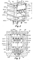
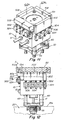
Fig. 1 is a top perspective view of an assembly of a top clamp plate, a heated manifold and a pair of actuators mounted on the heated manifold, each actuator having a housing and heat convectors mounted in an arrangement according to one embodiment of the invention. -
Fig. 2 is a front perspective view of one of the actuators of theFig. 1 assembly. -
Fig. 3 is a sectional view taken along lines 3-3 ofFig. 1 . -
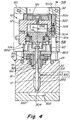
Fig. 4 is a sectional view taken along lines 4-4 ofFig. 1 . -
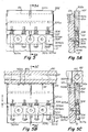
Fig. 5 is a fragmentary front view as seen along lines 5-5 ofFig. 2 . -
Fig. 5B is a front view similar toFig. 5 but showing the heat convector and actuator in use with clamping plate installed. -
Fig. 5C is a cross-sectional side view taken along lines 5B-5B ofFig. 5A . -
Fig. 5D is a front view similar toFig. 5B but showing heat pipes alternatively and additionally mounted vertically in the heat transmitter elements and actuator body. -
Fig. 5E is a cross-sectional side view taken alonglines 5E-5E ofFig. 5D . -
Fig. 5F is a front view similar toFig. 5D but with additional heat pipes mounted horizontally to the heat transmitter elements. -
Fig. 5G is a cross-sectional side view taken alonglines 5G-5G ofFig. 5F . -
Fig. 5H is a front view similar toFig. 5 but showing rods formed integrally with the upper heat transmitter element. -
Fig. 5I is a cross-sectional side view taken along lines 5I-5I ofFig. 5H . -
Fig. 5J is a front view similar toFig. 5H but showing heat pipes embedded within the rods and upper heat transmitter element. -
Fig. 5K is a cross-sectional side view taken alongline 5K-5K ofFig. 5J . -
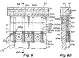
Fig. 6 is a front view similar toFig. 5 but showing the slidable rods affixed to the lower heat transmitting element. -
Fig. 6A is a cross-sectional side view taken alonglines 6A-6A ofFig. 6 . -
Fig. 7 is a top perspective view of an actuator having a single cooling device mounted to a side wall of the actuator where the cooling device comprises aproximal base 504 and a distal plate member that is spring loadably mounted on the base with thedistal plate 502 in slidable engagement contact with a surface of the housing of the actuator. -
Fig. 8 is a side view ofFig. 7 additionally showing a top clamp plate with the distal plate member in spring loaded engagement therewith. -
Fig. 9 is a top perspective view of an actuator having two cooling devices mounted to two separate side walls of the actuator where the cooling devices comprise aproximal base 504 and adistal plate member 502 that is spring loadably mounted on the base 504 with the distal plates being 502 in slidable engagement contact with a surface of the housing of the actuator. -
Fig. 10 is a side view ofFig. 9 additionally showing a top clamp plate with thedistal plate members 502 of the heat transmissive members in spring loaded engagement therewith. -
Fig. 11 is a top perspective view of an actuator having four separate cooling devices mounted to four separate side walls of the actuator where the cooling devices each comprise aproximal base 504 and adistal plate member 502 that is spring loadably mounted on the base 504 with the distal plates being 502 in slidable engagement contact with a surface of the housing of the actuator. -
Fig. 12 is a side view ofFig. 11 additionally showing a top clamp plate with thedistal plate members 502 of the heat transmissive members in spring loaded engagement therewith. -
Fig. 13 is is a top perspective view an actuator in thermal communication with a heated manifold of an injection molding system with two separate cooling devices mounted to sides of the actuator where each cooling device comprises a proximal base and a distal plate spring loadably mounted on the base with the plates in slidable engagement contact with a surface of the actuator and further with a third cooling device mounted to a side wall of the actuator where the third cooling device comprises a proximal base and a distal plate spring loadably mounted on the base with the distal plate in spring loaded arrangement to move side-to-side as opposed to upstream downstream. -
Fig. 14 is a side view ofFig. 13 additionally showing a top clamp plate assembled together with the actuator and cooling devices with thedistal plate members 502 of the heat transmissive members of the cooling devices in spring loaded engagement with the top clamp plate. -
Fig. 15 is a top perspective view of an actuator in thermal communication with a heated manifold of an injection molding system with a single cooling device attached to the actuator where the cooling device comprises one exemplary configuration of a unitary body of metal material attached at a proximal base ormember end 504 to the actuator having adistally extending arm 502 of one configuration, the distally extending arm of the unitary body being engageable at a distal end surface with a top clamp plate when the system is assembled such that a distal end surface of the distally extending arm deforms under spring force to maintain the distal end surface of the arm in compressed contact with the top clamp plate. -
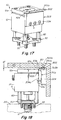
Fig. 16 is a side view of theFig. 15 embodiment showing the actuator assembled together with a top clamp plate and the distal arm member in spring loaded compressed engagement with the top clamp plate. -
Fig. 17 is a top perspective view of an actuator in thermal communication with a heated manifold of an injection molding system with a single cooling device attached to the actuator where the cooling device comprises another exemplary configuration of a unitary body of metal material attached at a proximal base ormember end 504 to the actuator having adistally extending arm 502 of another configuration, the distally extending arm of the unitary body being engageable at a distal end surface with a top clamp plate when the system is assembled such that a distal end surface of the distally extending arm deforms under spring force to maintain the distal end surface of the arm in compressed contact with the top clamp plate. -
Fig. 18 is a side view of theFig. 17 embodiment showing the actuator assembled together with a top clamp plate and the distal arm member in spring loaded compressed engagement with the top clamp plate. -
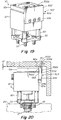
Fig. 19 is a top perspective view of an actuator in thermal communication with a heated manifold of an injection molding system with a single cooling device attached to the actuator where the cooling device comprises another exemplary configuration of a unitary body of metal material attached at a proximal base ormember end 504 to the actuator having adistally extending arm 502 of another configuration, the distally extending arm of the unitary body being engageable at a distal end surface with a top clamp plate when the system is assembled such that a distal end surface of the distally extending arm deforms under spring force to maintain the distal end surface of the arm in compressed contact with the top clamp plate. -
Fig. 20 is a side view of theFig. 19 embodiment showing the actuator assembled together with a top clamp plate and the distal arm member in spring loaded compressed engagement with the top clamp plate. -
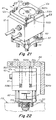
Fig. 21 is a top perspective view of another embodiment showing an actuator in thermal communication with a heated manifold of an injection molding system with four separate cooling devices that each comprise a rod or tube spring loadably mounted within a complementary precision formed receiving bore drilled in body of the housing of the actuator, the rods or tubes being adapted for slidable engagement contact against an internal surface of the precision formed receiving bores. -
Fig. 22 is a side view of theFig. 21 embodiment showing the actuator assembled together with a top clamp plate and the rods or tubes being in spring loaded compressed engagement with the top clamp plate. -
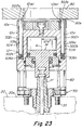
Fig. 23 is a front view of theFig. 21 embodiment showing the actuator assembled together with a top clamp plate and the rods or tubes being in spring loaded compressed engagement with the top clamp plate. -
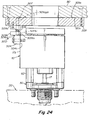
Fig. 24 is a side view of another embodiment showing a cooling device comprised of an assembly of a distal heat transmissive plate member assembled together with a spring loading mechanism, the assembly being that is readily mountable to or between the actuator and a top clamp plate such that when the top clamp plate and the actuator and the assembly are assembled together into operating configuration, the distal heat transmissive plate member is spring loadably engaged against the top clamp plate and heat transmissively engaged with a proximal heat transmissive base member that is mounted to the actuator housing. -
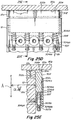
Fig. 25A is a top perspective view of an actuator assembled together with another embodiment of a pair of cooling devices comprised of sliding rods and a sliding block mounted within a base attached to the actuator. -
Fig. 25B is a front right side perspective view of an assembly of a manifold, an actuator with cooling devices as inFigs. 25A-25E and a top clamp plate configured to assemble together quickly that the actuator and cooling devices so tht spring loaded rods and block of thecooling devices 500 attached to the actuator will engage with the underside of a quickly assemblable plate component of the top clamp plate. -
Fig. 25C is an exploded view of the device ofFig. 25B . -
Fig. 25D is a cross-sectional view taken along lines 25D-25D ofFig. 25A . -
Fig. 25E is a cross-sectional view taken alonglines 25E-25E ofFig. 25D . -
Fig. 25F is a cross-sectional view taken alonglines 25F-25F ofFig. 25A . -
Fig. 25G is a cross-sectional view taken alonglines 25G-25G ofFig. 25F . - The embodiments shown in
figures 15-24 are reference embodiments not covered by the claimed invention. - In the
Figs. 1-3 embodiment, theapparatus 5 includes acooling device 800 that is formed having aproximal mount 803 that is mounted between the downstream end of theactuator housing 12 and theheated manifold 20. A pair of upstream extending legs 800l extend upstream from themount 803. Thecooling device 800 is formed and adapted to form a reception aperture or recess 800ra that is complementary to and receives theactuator housing 12 such that the legs 800l are disposed in close proximity to the lateral outer surfaces 12los of theactuator housing 12. The legs 800l are formed to have an upstream extending longitudinal length UL that disposes the distal-most edge surface 800a of the legs 800l upstream beyond theupstream-most extending surface 12u of theactuator 12 when theactuator 12 is mounted in operating format within the reception aperture 800ra. The legs 800l are configured to have one orspring joints 800s along the longitudinal length UL of the legs 800l.Spring joints 800s are resiliently deformable such that when the legs 800l are subject to a compressive force along the longitudinal length UL of thelegs 8001, the spring joints exert a spring force UF. The longitudinal length UL of thelegs 8001, theclamp plate 80,manifold 20,actuator housing 12 and their mounting and interconnection components are selected, arranged and formed such that when theclamp plate 80,manifold 20,actuator 12 andcooling device 800 are assembled into operating format, theundersurface 80a of the clamp plate intimately engages with the distal end surface 800a under compression to cause the spring joints 800s to exert the UF force by surface 800a againstsurface 80a. Similarly, the same components are formed and arranged together with the formation and arrangement ofcooling device 500 such that the distal endmost surface 502a ofdistal member 502 engages theundersurface 80a ofplate 80 under compression from spring load force SF,Fig. 3 , exerted bysprings 506 ofcooling device 500 when all such components are assembled into operating format. - As shown in all embodiments described herein where independent springs such as shown in
Figs. 1-14 ,21-25G are employed, such springs comprise a conventional spring having an upper end 506u and a lower end 506l that respectively engage against and between a complementary engagement surface of thedistal member proximal member 504, 504aa such that thespring 506 is compressed and thedistal member 502 is forcibly urged under the force UF of the spring when compressed in an upstream direction to compress thedistal end surface undersurface 80a of the clampingplate 80. -
Figs. 1-25G show aninjection molding apparatus 5 comprised of anactuator 10 having ahousing body heated manifold 20 into whichfluid injection material 102 is injected from aninjection machine 100 into and through one or moremanifold distribution channels 22 that deliver fluid downstream to a downstreamfluid delivery channel 200 such as the bore of a nozzle that terminates at its downstream end in agate 304 that communicates with thecavity 302 of amold 300. Theactuator 10 includes apiston 14 that is controllably drivable along a drive axis A in a reciprocal upstream and downstream direction together with avalve pin 17 that is interconnected to thepiston 14. Thevalve pin 17 is mounted within a complementary receiving aperture 91a of abushing 91, the outside surface of thepin 17 mating with an interior surface of the aperture 91a and being slidable in an upstream and downstream direction axial A direction within the aperture 91a of thebushing 91 such that injection fluid that flows throughchannels bushing 91 is fixedly mounted within the body of theheated manifold 20 viabushing screw 92 that is screwably engaged within a complementary threaded receiving aperture bored within theheated manifold 20. Thebushing 91,screw 92,actuator 10 andvalve pin 17 are all adapted and arranged such that thevalve pin 17 is controllably drivable upstream and downstream through both themanifold distribution channel 22 and thedownstream nozzle channel 200 between a downstream-most gate closed position and one or more upstream gate open positions. - As shown in the
Figs. 1 ,4 embodiment, theactuator housing 12 is typically mounted axially A upstream of and on or to theheated manifold 20. Theactuator 10 can be mounted on or to the manifold via either or both mounts orspacers 60 and a water cooled cooling device or mount 803 as disclosed inU.S. patent no. 8,349,244 . The downstreamaxially facing surface 12d of theactuator housing 12 is also typically mounted on or to thestabilization mount 50. As shown, thecooling mount 803 andspacers 60 are mounted on or to an upstream surface of thestabilization mount 50. The downstreamaxially facing surface 12d of theactuator housing 12 is mounted in direct heat or thermally conductive contact with one or more of themounts valve pin 17. - One or more of the
mounts heated manifold 20 through themounts actuator body 12 that is spaced laterally 12ld from the drive axis A of theactuator 10 and valve pin 17 a distance 12ld sufficient to prevent or substantially retard conduction of heat through ambient air or through thehousing body 12,valve pin 17 or mounts 50, 60, 803. To the extent that heat is conducted or communicated from theheated manifold 20 to thehousing body 12 such heat is conducted from thehousing body 12 to theproximal member 504, 504aa further to thedistal member 502, 502u and finally to thecool clamp plate 80 as described herein. - In all of the
Figs. 4-25G embodiments, thecooling device 500 comprises a heat transmitter that is comprised of a distal arm or member orassembly member 504, the distal arm ormember 502 or assembly being mounted by a spring loadable interconnection orengagement 506 to or with a proximal base ormember 504, 504a, 504aa. The proximal base ormember 504, 504a, 504aa is preferably mounted such that a complementary surface of themember 504, 504a, 504aa is disposed or mounted in intimate or compressed thermally conductive contact on, to or against a surface 12ls, 12si of thehousing body 12 that is spaced laterally 12ld away from the axis A of theactuator 10 andvalve pin 17. The location of the mounting of theproximal member 504, 504a, 504aa is arranged such that the proximal base ormember 504 is spaced laterally apart from contact with the axially mounted actuator mounts 50, 60, 803 that are directly mounted in close adjacency to and in thermal communication with theheated manifold 20 and on which theproximal end 12d of theactuator housing 12 is directly axially A mounted. - The distal arm or
member 502 is preferably comprised of a highly thermally conductive material and has adistal end surface 502a that is adapted to compressibly engage against anundersurface 80a of theclamp plate 80 under a spring load from the springloadable interconnection 506 between thedistally extending arm 502 and the proximal base ormember 504 when all components of thesystem 5 are fully assembled and the heated manifold is brought up to an elevated operating temperature. Thesystem 5 can be adapted and arranged such that thedistal end surface 502a is not engaged under a compressive force when the system is in a cold non operating condition when thesystem 5 is initially assembled before the manifold 20 is heated to operating temperature or when thesystem 5 is shut down and allowed to return to room temperature after the manifold 20 has been heated up to operating temperature. - Thus the
system 5 is preferably adapted and arranged such that compressive force betweendistal end surface 502a and thesurface 80a of theclamp plate 80 occurs only when thesystem 5 includingmanifold 20 is brought up to normal elevated operating temperature. In theFigs. 4-14 and21-25G embodiments where thedistal arm 502 orrod 502r comprises a heat conductive independent body that is independent of and mounted on an independentcompressible spring body 506, the degree of upstream and downstream movement Q along or substantially parallel to the axis A, ranges from 0 mm when thesystem 5 is in a cold or room temperature condition up to a maximum of about 3 mm when thesystem 5 is brought up to normal elevated operating temperature (such as between about 150 and 450 degrees F). Similarly, in the embodiment shown inFigs. 13, 14 where thearm 502 is arranged and adapted for lateral L movement relative to the axial direction A of theactuator 10, the degree of lateral movement Q',Fig. 14 , ranges from 0 mm when thesystem 5 is in a cold or room temperature condition up to a maximum of about 3 mm when thesystem 5 is brought up to normal elevated operating temperature. Theindependent spring body 506 in theFigs. 1-14 ,21-24 embodiments is resilient such that after being compressed Q by up to about 3 mm when the system is at operating temperature, theindependent spring body 506 will return back to its original uncompressed or non-compressed axial spring length or state when the system returns to room temperature. - In the
Figs. 15-20 embodiments where theheat transmitting device 500 comprises a unitary orintegral body distal arm 502 along or substantially parallel to the axis A, ranges from 0 mm when thesystem 5 is in a cold or room temperature condition up to a maximum of about 0.5 mm when thesystem 5 is brought up to normal elevated operating temperature (such as between about 150 and 450 degrees F). Thespring 506 in theFigs. 15-20 embodiments that is integral with the bodies ofarm 502 andbase 504, is resilient such that after being compressed Q" by up to about 0.5 mm when the system is at operating temperature, theintegral spring body 506 will return back to its original uncompressed or non-deformed axial length or state when the system returns to room temperature. - The
arm 502 has an exterior or proximally disposedsurface 502b for making contact with and receiving heat from the actuatorhousing body components exterior arm surface 502b and a laterally disposed complementary mating surface 12ls, 12as of thehousing body 12. Thearm 502 transmits heat received via theproximal surface 502b to thedistal end surface 502a and in turn to the relativelycool clamp plate 80 via compressed engagement betweensurface 502a and acomplementary undersurface 80s of theclamp plate 80. - In the
Figs. 5-14 ,24-25G embodiments, thearm actuator housing 12 by transmission of heat through rods ortubes 507 which in turn receive heat from thebase member 504 which itself receives heat from theactuator housing 12 by intimate compressed engagement with an exterior laterally disposed surface 121 of thehousing 12. The laterally disposed actuator surface 121 of thehousing 12 is spaced a lateral distance 12ld away from the drive axis A of thevalve pin 17 because thevalve pin 17 comes into direct thermal contact with theheated injection fluid 102. Thus theheat transmission device 500 is disposed in a laterally spaced position away from thevalve pin 17 and the valve pin axis A such that thebase 504 is removed from direct thermal contact or thermal communication with the axis or thevalve pin 17. In such embodiments, theproximal base member 504 is rigidly attached to the lateral actuator surface 121 such as via a bolt or screw 504s such that acomplementary surface 504b of thebase member 504 is engaged in intimate heat conductive contact with the lateral disposed surface 121 that is spaced laterally 12 ld from the axis. - Similarly in the
Figs. 21-23 embodiments, thebase 504 of therods 502r are engaged with a laterally disposed actuator surface 12si that is spaced a lateral distance 12ld away from the drive axis A of thevalve pin 17. Thus theheat transmission rods 502r are disposed in a laterally spaced position away from themounts valve pin 17 and axis A such that thebase 504 of therods 502r is removed from direct or closely adjacent thermal contact or communication with the axis A or thevalve pin 17. - In the
Figs. 21-23 embodiments, theactuator 10 comprises ahousing body Figs. 1-20 ,24 embodiments, the proximal base ormember 504 of thecooling device 500 is mounted to thehousing body 12 of theactuator 10 in an arrangement where thedistal end surface 502a of the distal arm ormember 502 makes compressed contact with theclamp plate surface 80a such that theend surface 502a moves or travels some distance relative to theactuator housing arm 502 is mounted. Thearm 502 anddistal engagement surface 502a is movable via thecompressible spring 506a toward and away from theactuator 10. - Similarly in the
Figs. 21-23 embodiment, the distally extending arm or rod ortube 502r is movable toward and away from theactuator housing 12 via acompressible spring 506a. The thermallyconductive rods 502r are mounted toproximal guides 504 which are in turn mounted to theactuator housing body 12. As shown, therods 502r are slidably disposed within complementary receiving apertures or bores 12bo bored into thehousing body 12. Therods 502r have anexterior surface 502b that are slidably engaged with an interior surface 12si, 12asi of thehousing bodies housing bodies rods 502r which in turn transmit heat to theclamp plate 80 via compressed contact betweensurface 502a andsurface 80a. Up and down movement of therods 502r within the apertures 12bo occurs with thesurfaces 502b and 12si and 12asi sliding against each other in engaged contact. - Similarly in the
Figs. 1-20 embodiments, the coolingdevices 500 are mounted and arranged such that the proximally disposedarm surfaces 502b are maintained in slidable engaged contact with the complementary housing body surfaces 12ls, 12as, thesurfaces 502b receiving heat from thehousing bodies clamp plate 80 via compressed contact betweensurfaces - In the
Figs. 15-20 embodiments, the distal arm ormember 502 and proximal base ormember 504 are formed as a singleunitary body 503 of highly conductive metal. The spring load in suchunitary bodies 503 is created via deformation of theunitary bodies 503 such that when theclamp plate 80,mold 300, manifold 20,actuator 10 andcooling device 503 are all assembled together, theunitary body 503 resiliently deforms under compression to travel to adifferent position 502d relative to theactuator housing 12 to which thebody 503 is mounted and relative to the original position 502o that the unitary body was disposed in prior tosurface 502a making contact withsurface 80a. Theunitary body 503 has an inherent resilience or inherent spring such that when the body is moved to thedeformed position 502d the inherent spring or resilience within thebody 503 causes thedistal end surface 502a to remain under forcible compressed contact with theundersurface 80a of theclamp plate 80. - In the
Figs. 13-14 embodiment, anothercooling device 505 according to the invention is shown where thedistally extending arm 502 moves radially toward and away from theactuator housing bodies cooling device 505 arrangement can be provided for exploiting the side-to-side or radial movement SS that theactuator 10 travels relative to theclamp plate 80 when the system is assembled in a cooled state and then subsequently the manifold 20 is heated to an elevated temperature. The heating of the manifold 20 subsequent to assembly of all of theclamp plate 80,mold 300, manifold 20,actuator 10 andcooling devices clamp plate 80. Such side-to-side or radial movement SS in the left or lateral direction L relative to the drive axis A of the actuator can be accounted for prior to assembly such that thedistal end surface 502a can be brought into compressed contact with thecomplementary mating surface 80a of the clamp plate with resilient compression being maintained by thespring 506a disposed between the proximal base ormember 504 and the heat transmission plate orelement 502. As with the above-described embodiments, thesurface 502a travels toward and away from thehousing bodies - The
Figs. 1-12 embodiments showcooling device 500 arrangements where thedistal arm 502 is adapted to move back and forth along a path of travel that is generally upstream and downstream or generally parallel to the drive axis A of the actuator orvalve pin 17 - With reference to
Figs. 5 - 6A , theproximal base member 504 is heat transmissively interconnected to or engaged with thedistal member 502 via aheat transmissive rod 507, the downstream end of which 507d is slidably mounted within a complementary precision bore 504pb that is drilled within thedistal mount member 502 such that thedownstream end 507d of therod 507 is engaged in heat transmissive intimate contact with an interior surface 504pbs of the bore 504pb. In such an embodiment, the upstream end 507us of therod 507 is screwably connected to thedistal member 502 into a complementary aperture withindistal member 502 such that when themember 502 travels through Q thedownstream end 507d is slidably moved along the path of travel Q together with movement ofdistal member 502. - In an alternative embodiment as shown in
Figs. 6, 6A , the upstream ends 507u of the heattransmissive rods 507 can conversely be slidably mounted within complementary bores 502pb provided indistal member 502 such that the exterior surface of theupstream end 507u of therod 507 is slidably and heat transmissively engaged against the interior surface 502pbs of the bore 502pb. In such an embodiment thedownstream end 507d of therod 507 is screwably connected toproximal mount member 504 such that when themember 502 travels through Q theupstream end 507u is slides along the interior surface 502pbs of the bore 502pb asmember 502 travels through the path of travel Q. - Thus, the rods or
tubes member 504 and the distal arm ormember 502 and rigidly interconnected to the other of the proximal base ormember 504 and the distal arm ormember 502. - In the embodiment shown in
Figs. 5H, 5I , the rods 507ir are formed integrally together with and as a part of the body of thedistal member 502, the outside surface 507os of the rods 507ir being engaged and slidable against the interior surface 504pbs of the receiving bores 504pb within the proximal mounts 504. As shown, thedistal member 502 is spring loaded byspring 506 that disposed between the distal 502 and proximal 504 heat transmissive members. - In another embodiment of the invention,
Figs. 5D, 5E, 5F, 5G one or the other of the distal 502 and proximal 504 members can have one or more highly heat conductive tube members that contain a heatconductive fluid members tubes 507 can comprise and be adapted to contain a heat conductive fluid such astube 517r shown inFigs. 5D, 5E, 5F, 5G ,5J, 5K . Such heatconductive tubes actuator housing 12, theproximal member 504 and the distal member. An example of the structure and configuration of such heat conductive tubes is disclosed inU.S. Patent No. 4,500,279 . - Similarly, such heat conductive tubes 517ah can be embedded within the body of the
actuator housing 12 as shown inFig. 5F, 5G in the same manner as described above where thetubes members - With reference to
Figs. 25A-25G theactuator 12 of theapparatus 5 has a pair of cooling devices each having a base member 504aa. One of the twocooling devices 500 has cylindrical slots 504pb, 504pba that receive a complementary rod shapedmember 507m comprised of anupper rod portion 507u connected to alower rod portion 507d. The upper 507u and lower 507d portions ofrod member 507m,Figs. 25F, 25G are connected to each other and are both respectively slidably mounted within the complementary slots 504pb, 504pba for upstream and downstream movement UD. The configuration of the upper and lower 507u, 507d rod portions of therod 507m is adapted so that the outside surfaces 507us, 507ds of therod 507m are in slidable heat conductive engagement with the inside surfaces 504pbs, 504pbsa of the base member 504aa. The base member 504aa is mounted in heat conductive engagement with the outside surface ofactuator housing 12. The base member 504aa is mounted such that it is spaced 12ls a lateral distance 12ld from the axis A of thevalve pin 17 andhousing 12 whereby the surface 12ls and the base member 504aa are laterally spaced apart from direct heat conductive communication with theheat manifold 20. Therod 507m is mounted such that therod 507m is spring load biased viaspring 506 which exerts upstream directed force UF to urge thedistal end surface 507a of therod 507m into contact heat conductive engagement with asurface 80a of thetop clamp plate 80. As in embodiments described above,rods actuator housing 12, theproximal member 504, the walls of thetube 507m and theclamp plate 80. As with proximalheat conducting member 502, in such an embodiment where therods distal end surface 507a of the rod or tube engages asurface 80a under compression via a spring load fromspring 506 or otherwise. - Similarly with reference to
Figs. 25D, 25E the other cooling device of theFigs. 25A-25G embodiment comprises a base member 504aa in which a rectangular shaped distal arm ormember 502 is slidably mounted in a complementarily shaped slot 504sb. The rectangular arm ormember 502 is connected torods 507 having alower rod member 507d that are slidably received within complementary slots 504pb. The outside surfaces 507ds of thelower rod 507d portion,Fig. 25E are in slidable heat conductive engagement with the inside surfaces 504pbs of the base member 504aa. The distal rectangularheat conducting member 502 is slidably received within the complementary receiving aperture 504sb such that theoutside surface 502s ofdistal arm 502 is in slidable heat conductive engagement with the inside surface 504is of the slot 504sb. Theoutside surface 502s of thedistal arm 502 is also preferably mounted such thatsurface 502s is in slidable heat conductive engagement with the outside surface 12as of theupstream actuator member 12a and surface 12ls. The base member 504aa is mounted in heat conductive engagement with the outside surface 12ls ofactuator housing 12. Theslidable mounting rod rod 507 is spring load biased viaspring 506 which exerts upstream directed force UF to urge thedistal end surface 502a of thedistal arm 502 into heat conductive engagement with asurface 80a of thetop clamp plate 80. -
Figs. 25A - 25C show an assembly of theFig. 25A actuator 12 with the pair of coolingdevices 500 attached to the actuator housing together with a manifold 20 and atop clamp plate 80. Thetop clamp plate 80 is formed with a receiving aperture 80ra for insertion of theactuator 12 and cooling device subassembly that enables the actuator to be mounted on the manifold 20 and surrounded by the top clamp plate as shown. The upstream end of thetop clamp plate 80 has arecess 80r formed in a complementary configuration to aplate 80p that is insertable within therecess 80r in an upstream position relative to theactuator housing 12 and its attachedcooling devices 500 such that thedistal end surfaces 502a of the heattransmissive rods 507m and theheat transmissive block 502,Figs. 25A-25G , engage theundersurface 80a of theclamp plate 80p under spring loaded compression. Theplate 80p is readily attachable to and detachable from the upstream end surface of theclamp plate 80 via screws or bolts 80t after theactuator 12 with attachedcooling devices 50 has been inserted in the receiving aperture 80ra and mounted on themanifold 20.
Claims (17)
- An injection molding apparatus (5) comprising a clamp plate (80), a heated manifold (20), an actuator (10) interconnected to a valve pin (17) having an axis (A), a mold (300) and a cooling device (500) that cools the actuator (10) wherein, when assembled, the clamp plate (80) mounted upstream of the mold (30), the manifold (20) being disposed between the clamp plate and the mold, wherein the actuator (10) comprises a housing body (12) that is mounted in thermally conductive contact along the axis (A) to one or more actuator mounts (50, 60, 803) that are mounted downstream in heat conductive communication with or contact with or on the manifold along the axis (A),
wherein the cooling device (500) comprises:a heat transmitter comprising a proximal arm or member (504) comprised of a heat conductive material and a distal arm or member (502) comprised of a thermally conductive material, the distal arm or member or member (502) being mounted by a spring loadable interconnection or engagement (506) on or to the proximal base or member (504), the distal arm or member (502) having a distal end surface (502a) for engaging the clamp plate (80, 80a) under a spring load and a proximal surface (502b) for transmitting heat from the proximal surface to the distal end surface (502a),the housing body (12) having a surface (12ls) that is spaced laterally (12ld) from the axis (A), the proximal surface (502b) being adapted to be engaged and slidable against a lateral surface (12ls) of the housing body (12) of the actuator (10) such that heat thermally conducts between the housing body (12) and the distal arm or member 502 and such that the distal base or member (502) is spaced laterally apart from contact with the one or more actuator mounts (50, 60, 803) in an arrangement wherein the distal end surface (502a) of the distal arm or member (502) is movable through the spring loadable interconnection (506) toward and away from the actuator (10),the clamp plate, the mold (300), the manifold, the actuator and the heat transmitter being assemblable together in an arrangement wherein the spring loadable interconnection (506) is loaded urging the distal end surface (502a) of the distal arm or member (502) into compressed engagement with the clamp plate (80), (80a) at least when the manifold is heated to an elevated operating temperature. - The apparatus of claim 1 further comprising one or more heat conductive tubes (517a, 517b, 517c, 517d) containing a heat conductive liquid embedded within one or the other or both of the proximal (504) and distal (502) members.
- The apparatus according to any of the foregoing claims wherein the distal (502) and proximal (504) members are heat transmissively interconnected or engaged with each other by heat transmissive rods (507) or tubes (517r) that are intimately engaged with the members (502, 504).
- The apparatus according to any of the foregoing claims further comprising one or more hollow heat conductive tubes (517ah) having a cavity containing heat conductive fluid, the one or more tubes (517ah) being embedded within the body of the housing of the actuator (10, 12).
- The apparatus according to any of the foregoing claims wherein the spring loaded interconnection (506) is adapted to urge the distal end surface (502a) of the distal arm or member into a compression of at least 0,0689476 bar (1 pound per square inch (psi)) with the clamp plate.
- The apparatus according to any of the foregoing claims wherein the lateral surface (12ls) and the base member (504aa) are laterally spaced apart (12ld) from direct heat conductive communication with the heat manifold (20).
- The apparatus according to any of the foregoing claims wherein the clamp plate is cooled.
- The apparatus according to any of the foregoing claims wherein the cooling device (500) includes a resilient spring (506a) disposed between a body surface (504a) of the proximal base or member (504) and the distal arm or member (502), wherein the clamp plate, the mold, the manifold, the actuator and the cooling device are assembled together in an arrangement wherein the spring (506a) is resiliently compressed up to a maximum of about 3 mm urging the distal end surface (502a) of the distal arm or member into compressed engagement with the clamp plate (80a).
- The apparatus according to any of the foregoing claims wherein the apparatus includes two or more separate cooling devices each comprised of a distal arm or member mounted in spring loadable interconnection to a proximal base or member, each separate cooling device being separately mounted to the housing body (12, 12a) of the actuator and separately assemblable together with the clamp plate, the mold, the actuator and the manifold such that the distal end surface of the distal arm or member of each separate cooling device is in compressed engagement with the clamp plate under the spring loadable interconnection (506) between each separate distal end arm (502) and proximal base or member (504).
- The apparatus according to any of the foregoing claims further comprising a mount (803) separating the actuator housing from direct contact with the manifold, the mount being cooled and having an upstream mounting surface in thermally conductive communication with a complementary mounting surface (12d) of the actuator (10) and a downstream mounting surface in thermally conductive communication with the manifold (20).
- The apparatus according to any of the foregoing claims wherein the mount is comprised of a thermally conductive metal that is cooled to a temperature of less than about 65,56 °C (150 degrees F).
- The apparatus according to any of the foregoing claims wherein the actuator (10) is interconnected to a valve pin (17) that is mounted to the manifold and extends through a fluid material feed bore (22) in the manifold (20).
- The apparatus according to any of the foregoing claims wherein the proximal base or member (504) is rigidly attached in thermally conductive contact to the laterally spaced surface (12ls) the housing body (12, 12a).
- The apparatus according to any of the foregoing claims wherein the distal arm or member (502) and proximal member (504) comprise a unitary thermally conductive body (503) with at least the distal arm or member (502) being resiliently deformable to form the spring loadable interconnection (506) on assembly of the clamp plate, the mold, the manifold, the actuator and the heat transmitter being assembled in an arrangement wherein the spring loadable interconnection (506) is loaded when the manifold is heated to operating temperature urging the distal end surface (502a) of the distal arm or member into compressed engagement with the clamp plate.
- The apparatus according to any of the foregoing claims wherein the distal arm or member and the proximal base or member comprise a unitary body (503) rigidly attached in thermally conductive contact (504s) to the laterally spaced surface (12ls), a portion of the unitary body being resiliently deformable to form the spring loadable interconnection (506), the mold, the manifold, the actuator and the heat transmitter being assembled in an arrangement wherein the resiliently deformable portion of the unitary body (503) compresses up to a maximum of about 0.5 mm when the manifold is heated to operating temperature urging the distal end surface (502a) of the distal arm or member into compressed engagement with the clamp plate.
- The apparatus according to any of the foregoing claims wherein the distal arm or member (502, 502b) is attached to the actuator such that the arm (502, 502b) is disposed in slidable thermally conductive contact with the lateral surface (12ls, 12as) of the housing body.
- A method of cooling the actuator of the apparatus according to any of the foregoing claims comprising assembling the clamp plate, the mold, the manifold, the actuator and the cooling device of the apparatus of claim 1 such that the spring loadable interconnection is loaded urging the distal end surface of the distal arm or member into compressed engagement with the clamp plate.
Priority Applications (1)
| Application Number | Priority Date | Filing Date | Title |
|---|---|---|---|
| EP20177950.1A EP3744498A1 (en) | 2015-03-20 | 2016-02-08 | Actuator cooling apparatus and method |
Applications Claiming Priority (6)
| Application Number | Priority Date | Filing Date | Title |
|---|---|---|---|
| US201562135871P | 2015-03-20 | 2015-03-20 | |
| US201562154320P | 2015-04-29 | 2015-04-29 | |
| US201562170937P | 2015-06-04 | 2015-06-04 | |
| US201562192815P | 2015-07-15 | 2015-07-15 | |
| PCT/US2016/016944 WO2016153608A1 (en) | 2015-03-20 | 2016-02-08 | Actuator cooling apparatus and method |
| EP16708252.8A EP3240666B1 (en) | 2015-03-20 | 2016-02-08 | Actuator cooling apparatus and method |
Related Parent Applications (2)
| Application Number | Title | Priority Date | Filing Date |
|---|---|---|---|
| EP16708252.8A Division EP3240666B1 (en) | 2015-03-20 | 2016-02-08 | Actuator cooling apparatus and method |
| PCT/US2016/016944 Previously-Filed-Application WO2016153608A1 (en) | 2011-11-23 | 2016-02-08 | Actuator cooling apparatus and method |
Related Child Applications (3)
| Application Number | Title | Priority Date | Filing Date |
|---|---|---|---|
| EP20177950.1A Division EP3744498A1 (en) | 2015-03-20 | 2016-02-08 | Actuator cooling apparatus and method |
| EP20177950.1A Previously-Filed-Application EP3744498A1 (en) | 2015-03-20 | 2016-02-08 | Actuator cooling apparatus and method |
| EP20177950.1A Division-Into EP3744498A1 (en) | 2015-03-20 | 2016-02-08 | Actuator cooling apparatus and method |
Publications (2)
| Publication Number | Publication Date |
|---|---|
| EP3581359A1 EP3581359A1 (en) | 2019-12-18 |
| EP3581359B1 true EP3581359B1 (en) | 2021-08-18 |
Family
ID=55456898
Family Applications (9)
| Application Number | Title | Priority Date | Filing Date |
|---|---|---|---|
| EP16708252.8A Active EP3240666B1 (en) | 2015-03-20 | 2016-02-08 | Actuator cooling apparatus and method |
| EP19163620.8A Active EP3581359B1 (en) | 2015-03-20 | 2016-02-08 | Actuator cooling apparatus and method |
| EP20177950.1A Withdrawn EP3744498A1 (en) | 2015-03-20 | 2016-02-08 | Actuator cooling apparatus and method |
| EP16713646.4A Active EP3247546B1 (en) | 2015-03-20 | 2016-02-16 | Actuator cooling apparatus and method |
| EP16711394.3A Not-in-force EP3271129B1 (en) | 2015-03-20 | 2016-02-25 | Actuator cooling apparatus |
| EP18151044.7A Active EP3326777B1 (en) | 2015-03-20 | 2016-02-25 | Actuator cooling method |
| EP16713153.1A Active EP3271130B1 (en) | 2015-03-20 | 2016-02-25 | Actuator cooling apparatus and method |
| EP18186892.8A Active EP3412425B1 (en) | 2015-03-20 | 2016-02-25 | Actuator cooling apparatus and method |
| EP16711393.5A Active EP3247545B1 (en) | 2015-03-20 | 2016-02-25 | Actuator cooling apparatus and method |
Family Applications Before (1)
| Application Number | Title | Priority Date | Filing Date |
|---|---|---|---|
| EP16708252.8A Active EP3240666B1 (en) | 2015-03-20 | 2016-02-08 | Actuator cooling apparatus and method |
Family Applications After (7)
| Application Number | Title | Priority Date | Filing Date |
|---|---|---|---|
| EP20177950.1A Withdrawn EP3744498A1 (en) | 2015-03-20 | 2016-02-08 | Actuator cooling apparatus and method |
| EP16713646.4A Active EP3247546B1 (en) | 2015-03-20 | 2016-02-16 | Actuator cooling apparatus and method |
| EP16711394.3A Not-in-force EP3271129B1 (en) | 2015-03-20 | 2016-02-25 | Actuator cooling apparatus |
| EP18151044.7A Active EP3326777B1 (en) | 2015-03-20 | 2016-02-25 | Actuator cooling method |
| EP16713153.1A Active EP3271130B1 (en) | 2015-03-20 | 2016-02-25 | Actuator cooling apparatus and method |
| EP18186892.8A Active EP3412425B1 (en) | 2015-03-20 | 2016-02-25 | Actuator cooling apparatus and method |
| EP16711393.5A Active EP3247545B1 (en) | 2015-03-20 | 2016-02-25 | Actuator cooling apparatus and method |
Country Status (4)
| Country | Link |
|---|---|
| US (2) | US10005215B2 (en) |
| EP (9) | EP3240666B1 (en) |
| CN (7) | CN107567377B (en) |
| WO (5) | WO2016153608A1 (en) |
Families Citing this family (29)
| Publication number | Priority date | Publication date | Assignee | Title |
|---|---|---|---|---|
| US10166709B2 (en) | 2011-11-23 | 2019-01-01 | Synventive Molding Solutions, Inc. | Actuator cooling apparatus and method |
| US10543629B2 (en) | 2014-12-11 | 2020-01-28 | Inglass S.P.A. | Method and apparatus for injection molding of plastic materials |
| CN107567377B (en) * | 2015-03-20 | 2019-10-01 | 圣万提注塑工业(苏州)有限公司 | Actuator cools down device and method |
| US11007695B2 (en) | 2015-03-20 | 2021-05-18 | Synventive Molding Solutions, Inc. | Actuator cooling apparatus and method |
| WO2019100085A1 (en) | 2017-11-14 | 2019-05-23 | Synventive Molding Solutions, Inc. | Actuator with eccentric pin drive |
| WO2020242510A1 (en) | 2019-05-28 | 2020-12-03 | Synventive Molding Solutions, Inc. | Partially rotated eccentric drive for valve pin |
| AT517390A1 (en) | 2015-07-03 | 2017-01-15 | Sonderhoff Engineering Gmbh | Dosing device for liquid plastic |
| CN110234488B (en) * | 2016-11-14 | 2022-04-05 | 圣万提注塑工业(苏州)有限公司 | Actuator cooling apparatus and method |
| CN108068272A (en) * | 2016-11-18 | 2018-05-25 | 柳道万和(苏州)热流道系统有限公司 | Housing assembly and with its Hot Runner System |
| WO2018169819A1 (en) | 2017-03-16 | 2018-09-20 | Synventive Molding Solutions, Inc. | Injection molding apparatus |
| EP3535106B1 (en) | 2017-03-20 | 2020-04-22 | Synventive Molding Solutions, Inc. | Valve pin positions and velocity control method and apparatus |
| WO2018183810A1 (en) | 2017-03-31 | 2018-10-04 | Synventive Molding Solutions, Inc. | Rotary valve |
| CN108724613A (en) * | 2017-04-14 | 2018-11-02 | 柳道万和(苏州)热流道系统有限公司 | Housing assembly and hot runner system with it |
| US11148333B2 (en) | 2017-04-18 | 2021-10-19 | Synventive Molding Solutions, Ino. | Linear to linear valve pin drive during injection cycle |
| EP3562642B1 (en) | 2017-04-26 | 2020-07-15 | Synventive Molding Solutions, Inc. | Double seal valve pin tip with vent |
| WO2019051196A1 (en) * | 2017-09-08 | 2019-03-14 | Commscope Technologies Llc | Heat dissipation enclosure |
| CN108381876B (en) * | 2018-03-08 | 2020-05-12 | 柳道万和(苏州)热流道系统有限公司 | Valve needle type hot runner cylinder |
| US11618194B2 (en) * | 2018-03-13 | 2023-04-04 | Inglass S.P.A. | Apparatus for injection molding of plastic materials |
| IT201800004581A1 (en) * | 2018-04-16 | 2019-10-16 | PLASTIC INJECTION MOLDING EQUIPMENT | |
| WO2020068285A1 (en) | 2018-08-17 | 2020-04-02 | Synventive Molding Solutions, Inc. | Disrupted flow through injection molding flow channel |
| CN113795365A (en) | 2019-02-25 | 2021-12-14 | 圣万提注塑工业(苏州)有限公司 | Cooled electric actuator controlled injection |
| EP3946881A1 (en) | 2019-04-02 | 2022-02-09 | Synventive Molding Solutions, Inc. | Nozzle heater |
| CN113811431B (en) | 2019-08-20 | 2023-10-13 | 圣万提注塑工业(苏州)有限公司 | Injection molding apparatus with integrated actuator electronic drive |
| US11958226B2 (en) | 2019-10-04 | 2024-04-16 | Husky Injection Molding Systems Ltd. | Stabilized adaptive hydraulic system pressure in an injection molding system |
| WO2021080767A1 (en) | 2019-10-21 | 2021-04-29 | Synventive Molding Solutions, Inc. | Electric actuator drive for injection molding flow control |
| CN115397644A (en) | 2020-02-20 | 2022-11-25 | 圣万提注塑工业有限公司 | Sequential injection of multiple mold cavities |
| WO2022005530A1 (en) | 2020-07-01 | 2022-01-06 | Synventive Molding Solutions, Inc. | Method and apparatus for controlled injection fluid flow |
| EP4225554A1 (en) | 2020-10-09 | 2023-08-16 | Synventive Molding Solutions, Inc. | Spring cushioned valve pin |
| CN116685451A (en) | 2020-12-08 | 2023-09-01 | 圣万提注塑工业有限公司 | Injection molding apparatus with cooling integrated actuator electric drive |
Family Cites Families (33)
| Publication number | Priority date | Publication date | Assignee | Title |
|---|---|---|---|---|
| US650401A (en) | 1899-11-03 | 1900-05-29 | Isaac W Lamb | Trunk-lid brace. |
| US4500279A (en) | 1983-07-06 | 1985-02-19 | Kona Corporation | Heat pipe manifold system |
| CA2010855C (en) * | 1990-02-23 | 1999-07-27 | Jobst Ulrich Gellert | Injection molding system having spring biased nozzles |
| CA2010961C (en) * | 1990-02-27 | 1997-03-11 | Harald Schmidt | Injection molding manifold having a pair of cooling bores on opposite sides of the melt passage |
| US6062840A (en) | 1997-09-02 | 2000-05-16 | Dynisco Hotrunners, Inc. | Hot runner system for coinjection molding |
| US5894025A (en) | 1997-06-13 | 1999-04-13 | Kona Corporation | Valve pin actuator |
| US6309208B1 (en) | 1997-06-13 | 2001-10-30 | Synventive Molding Solutions, Inc. | Apparatus for proportionally controlling fluid delivery to a mold |
| US6464909B1 (en) | 1998-04-21 | 2002-10-15 | Synventive Molding Solutions, Inc. | Manifold system having flow control |
| US6294122B1 (en) | 1998-06-26 | 2001-09-25 | Synventive Molding Solutions, Inc. | Electric actuator for a melt flow control pin |
| US6287107B1 (en) | 1997-09-02 | 2001-09-11 | Synventive Molding Solutions, Inc. | Apparatus for proportionally controlling fluid delivery to a mold |
| US6361300B1 (en) | 1998-04-21 | 2002-03-26 | Synventive Molding Solutions, Inc. | Manifold system having flow control |
| US7234929B2 (en) | 1999-09-21 | 2007-06-26 | Synventive Molding Solutions, Inc. | Injection molding flow control apparatus and method |
| US6343925B1 (en) | 2000-04-14 | 2002-02-05 | Husky Injection Molding Systems, Ltd. | Hot runner valve gate piston assembly |
| EP1223018B1 (en) | 2001-01-10 | 2005-05-25 | Synventive Molding Solutions B.V. | Injection moulding device a cooled valve pin guide bush |
| JP2002374653A (en) * | 2001-04-13 | 2002-12-26 | Namu:Kk | Motor actuator |
| WO2003057448A1 (en) | 2001-12-26 | 2003-07-17 | Synventive Molding Solutions, Inc. | Non-coaxial injection molding valve flow control |
| ATE362426T1 (en) * | 2003-02-04 | 2007-06-15 | Husky Injection Molding | HOT RUNNER DISTRIBUTION SYSTEM |
| CA2421801C (en) * | 2003-03-13 | 2010-02-23 | Denfred Holdings Ltd. | Automatic valve assembly for a water cooler reservoir |
| US10062273B2 (en) | 2010-09-28 | 2018-08-28 | Icontrol Networks, Inc. | Integrated security system with parallel processing architecture |
| WO2005113215A1 (en) * | 2004-05-14 | 2005-12-01 | University Of Massachusetts | Methods and devices for melt pressure regulation |
| US7329112B2 (en) | 2005-01-04 | 2008-02-12 | Plastic Engineering & Technical Services, Inc. | Injection molding system for injection molding a plurality of materials |
| US20070119504A1 (en) * | 2005-11-28 | 2007-05-31 | Yudo Co. Ltd. | Heat dissipating apparatus for cylinders of injection molding machines |
| EP2200799A4 (en) * | 2007-10-22 | 2012-08-29 | Mold Masters 2007 Ltd | Injection molding apparatus |
| CN101468511B (en) * | 2007-12-27 | 2012-02-29 | 高建鸣 | Passive pin valve |
| US8091202B2 (en) | 2009-05-06 | 2012-01-10 | Synventive Molding Solutions, Inc. | Method and apparatus for coupling and uncoupling an injection valve pin |
| EP2519392B1 (en) * | 2009-12-29 | 2014-03-05 | Synventive Molding Solutions, Inc. | Heating apparatus for fluid flow channel |
| WO2011119791A1 (en) * | 2010-03-25 | 2011-09-29 | Synventive Molding Solutions Inc., | Actuator mount system |
| IT1400794B1 (en) * | 2010-06-24 | 2013-07-02 | Sacmi | INJECTION SYSTEM |
| WO2014025674A1 (en) | 2012-08-06 | 2014-02-13 | Synventive Molding Solutions, Inc., | Injection molding apparatus and method for monitoring mold halves movement |
| WO2014194037A1 (en) * | 2013-05-29 | 2014-12-04 | Synventive Molding Solutions, Inc. | Valve pin position adjuster |
| WO2015183332A1 (en) * | 2013-05-29 | 2015-12-03 | Synventive Molding Solutions, Inc. | Actuator cooling apparatus and method |
| US9144929B2 (en) | 2012-08-06 | 2015-09-29 | Synventive Molding Solutions, Inc. | Apparatus and method for detecting a position of an actuator piston |
| CN107567377B (en) * | 2015-03-20 | 2019-10-01 | 圣万提注塑工业(苏州)有限公司 | Actuator cools down device and method |
-
2016
- 2016-02-08 CN CN201680014238.7A patent/CN107567377B/en active Active
- 2016-02-08 WO PCT/US2016/016944 patent/WO2016153608A1/en active Application Filing
- 2016-02-08 EP EP16708252.8A patent/EP3240666B1/en active Active
- 2016-02-08 EP EP19163620.8A patent/EP3581359B1/en active Active
- 2016-02-08 EP EP20177950.1A patent/EP3744498A1/en not_active Withdrawn
- 2016-02-16 CN CN201680011190.4A patent/CN107428055B/en active Active
- 2016-02-16 WO PCT/US2016/018042 patent/WO2016153632A1/en active Application Filing
- 2016-02-16 CN CN202010505741.0A patent/CN111823526B/en not_active Expired - Fee Related
- 2016-02-16 EP EP16713646.4A patent/EP3247546B1/en active Active
- 2016-02-25 CN CN201680016565.6A patent/CN107530932B/en not_active Expired - Fee Related
- 2016-02-25 CN CN201680027841.9A patent/CN107750202B/en not_active Expired - Fee Related
- 2016-02-25 WO PCT/US2016/019466 patent/WO2016153704A1/en active Application Filing
- 2016-02-25 EP EP16711394.3A patent/EP3271129B1/en not_active Not-in-force
- 2016-02-25 WO PCT/US2016/019461 patent/WO2016153703A1/en active Application Filing
- 2016-02-25 WO PCT/US2016/019469 patent/WO2016153705A1/en active Application Filing
- 2016-02-25 EP EP18151044.7A patent/EP3326777B1/en active Active
- 2016-02-25 CN CN202011628899.3A patent/CN112976502B/en active Active
- 2016-02-25 EP EP16713153.1A patent/EP3271130B1/en active Active
- 2016-02-25 EP EP18186892.8A patent/EP3412425B1/en active Active
- 2016-02-25 CN CN201680015650.0A patent/CN107530933B/en not_active Expired - Fee Related
- 2016-02-25 EP EP16711393.5A patent/EP3247545B1/en active Active
- 2016-07-07 US US15/204,555 patent/US10005215B2/en active Active
-
2018
- 2018-05-07 US US15/972,728 patent/US10632657B2/en active Active
Also Published As
Similar Documents
| Publication | Publication Date | Title |
|---|---|---|
| EP3581359B1 (en) | Actuator cooling apparatus and method | |
| US10889037B2 (en) | Actuator cooling apparatus and method | |
| US10625451B2 (en) | Actuator cooling apparatus and method | |
| US10953581B2 (en) | Actuator cooling apparatus and method | |
| US20210299927A1 (en) | Actuator cooling apparatus and method | |
| US10005216B2 (en) | Actuator cooling apparatus and method |
Legal Events
| Date | Code | Title | Description |
|---|---|---|---|
| PUAI | Public reference made under article 153(3) epc to a published international application that has entered the european phase |
Free format text: ORIGINAL CODE: 0009012 |
|
| STAA | Information on the status of an ep patent application or granted ep patent |
Free format text: STATUS: REQUEST FOR EXAMINATION WAS MADE |
|
| 17P | Request for examination filed |
Effective date: 20190319 |
|
| AC | Divisional application: reference to earlier application |
Ref document number: 3240666 Country of ref document: EP Kind code of ref document: P |
|
| AK | Designated contracting states |
Kind code of ref document: A1 Designated state(s): AL AT BE BG CH CY CZ DE DK EE ES FI FR GB GR HR HU IE IS IT LI LT LU LV MC MK MT NL NO PL PT RO RS SE SI SK SM TR |
|
| GRAP | Despatch of communication of intention to grant a patent |
Free format text: ORIGINAL CODE: EPIDOSNIGR1 |
|
| STAA | Information on the status of an ep patent application or granted ep patent |
Free format text: STATUS: GRANT OF PATENT IS INTENDED |
|
| INTG | Intention to grant announced |
Effective date: 20210414 |
|
| GRAS | Grant fee paid |
Free format text: ORIGINAL CODE: EPIDOSNIGR3 |
|
| GRAA | (expected) grant |
Free format text: ORIGINAL CODE: 0009210 |
|
| STAA | Information on the status of an ep patent application or granted ep patent |
Free format text: STATUS: THE PATENT HAS BEEN GRANTED |
|
| AC | Divisional application: reference to earlier application |
Ref document number: 3240666 Country of ref document: EP Kind code of ref document: P |
|
| AK | Designated contracting states |
Kind code of ref document: B1 Designated state(s): AL AT BE BG CH CY CZ DE DK EE ES FI FR GB GR HR HU IE IS IT LI LT LU LV MC MK MT NL NO PL PT RO RS SE SI SK SM TR |
|
| REG | Reference to a national code |
Ref country code: GB Ref legal event code: FG4D |
|
| REG | Reference to a national code |
Ref country code: CH Ref legal event code: EP |
|
| REG | Reference to a national code |
Ref country code: DE Ref legal event code: R096 Ref document number: 602016062582 Country of ref document: DE |
|
| REG | Reference to a national code |
Ref country code: IE Ref legal event code: FG4D Ref country code: AT Ref legal event code: REF Ref document number: 1421236 Country of ref document: AT Kind code of ref document: T Effective date: 20210915 |
|
| REG | Reference to a national code |
Ref country code: LT Ref legal event code: MG9D |
|
| REG | Reference to a national code |
Ref country code: NL Ref legal event code: MP Effective date: 20210818 |
|
| REG | Reference to a national code |
Ref country code: AT Ref legal event code: MK05 Ref document number: 1421236 Country of ref document: AT Kind code of ref document: T Effective date: 20210818 |
|
| PG25 | Lapsed in a contracting state [announced via postgrant information from national office to epo] |
Ref country code: SE Free format text: LAPSE BECAUSE OF FAILURE TO SUBMIT A TRANSLATION OF THE DESCRIPTION OR TO PAY THE FEE WITHIN THE PRESCRIBED TIME-LIMIT Effective date: 20210818 Ref country code: RS Free format text: LAPSE BECAUSE OF FAILURE TO SUBMIT A TRANSLATION OF THE DESCRIPTION OR TO PAY THE FEE WITHIN THE PRESCRIBED TIME-LIMIT Effective date: 20210818 Ref country code: ES Free format text: LAPSE BECAUSE OF FAILURE TO SUBMIT A TRANSLATION OF THE DESCRIPTION OR TO PAY THE FEE WITHIN THE PRESCRIBED TIME-LIMIT Effective date: 20210818 Ref country code: FI Free format text: LAPSE BECAUSE OF FAILURE TO SUBMIT A TRANSLATION OF THE DESCRIPTION OR TO PAY THE FEE WITHIN THE PRESCRIBED TIME-LIMIT Effective date: 20210818 Ref country code: HR Free format text: LAPSE BECAUSE OF FAILURE TO SUBMIT A TRANSLATION OF THE DESCRIPTION OR TO PAY THE FEE WITHIN THE PRESCRIBED TIME-LIMIT Effective date: 20210818 Ref country code: NO Free format text: LAPSE BECAUSE OF FAILURE TO SUBMIT A TRANSLATION OF THE DESCRIPTION OR TO PAY THE FEE WITHIN THE PRESCRIBED TIME-LIMIT Effective date: 20211118 Ref country code: PT Free format text: LAPSE BECAUSE OF FAILURE TO SUBMIT A TRANSLATION OF THE DESCRIPTION OR TO PAY THE FEE WITHIN THE PRESCRIBED TIME-LIMIT Effective date: 20211220 Ref country code: BG Free format text: LAPSE BECAUSE OF FAILURE TO SUBMIT A TRANSLATION OF THE DESCRIPTION OR TO PAY THE FEE WITHIN THE PRESCRIBED TIME-LIMIT Effective date: 20211118 Ref country code: AT Free format text: LAPSE BECAUSE OF FAILURE TO SUBMIT A TRANSLATION OF THE DESCRIPTION OR TO PAY THE FEE WITHIN THE PRESCRIBED TIME-LIMIT Effective date: 20210818 Ref country code: LT Free format text: LAPSE BECAUSE OF FAILURE TO SUBMIT A TRANSLATION OF THE DESCRIPTION OR TO PAY THE FEE WITHIN THE PRESCRIBED TIME-LIMIT Effective date: 20210818 |
|
| PG25 | Lapsed in a contracting state [announced via postgrant information from national office to epo] |
Ref country code: PL Free format text: LAPSE BECAUSE OF FAILURE TO SUBMIT A TRANSLATION OF THE DESCRIPTION OR TO PAY THE FEE WITHIN THE PRESCRIBED TIME-LIMIT Effective date: 20210818 Ref country code: LV Free format text: LAPSE BECAUSE OF FAILURE TO SUBMIT A TRANSLATION OF THE DESCRIPTION OR TO PAY THE FEE WITHIN THE PRESCRIBED TIME-LIMIT Effective date: 20210818 Ref country code: GR Free format text: LAPSE BECAUSE OF FAILURE TO SUBMIT A TRANSLATION OF THE DESCRIPTION OR TO PAY THE FEE WITHIN THE PRESCRIBED TIME-LIMIT Effective date: 20211119 |
|
| PG25 | Lapsed in a contracting state [announced via postgrant information from national office to epo] |
Ref country code: NL Free format text: LAPSE BECAUSE OF FAILURE TO SUBMIT A TRANSLATION OF THE DESCRIPTION OR TO PAY THE FEE WITHIN THE PRESCRIBED TIME-LIMIT Effective date: 20210818 |
|
| PG25 | Lapsed in a contracting state [announced via postgrant information from national office to epo] |
Ref country code: DK Free format text: LAPSE BECAUSE OF FAILURE TO SUBMIT A TRANSLATION OF THE DESCRIPTION OR TO PAY THE FEE WITHIN THE PRESCRIBED TIME-LIMIT Effective date: 20210818 |
|
| REG | Reference to a national code |
Ref country code: DE Ref legal event code: R097 Ref document number: 602016062582 Country of ref document: DE |
|
| PG25 | Lapsed in a contracting state [announced via postgrant information from national office to epo] |
Ref country code: SM Free format text: LAPSE BECAUSE OF FAILURE TO SUBMIT A TRANSLATION OF THE DESCRIPTION OR TO PAY THE FEE WITHIN THE PRESCRIBED TIME-LIMIT Effective date: 20210818 Ref country code: SK Free format text: LAPSE BECAUSE OF FAILURE TO SUBMIT A TRANSLATION OF THE DESCRIPTION OR TO PAY THE FEE WITHIN THE PRESCRIBED TIME-LIMIT Effective date: 20210818 Ref country code: RO Free format text: LAPSE BECAUSE OF FAILURE TO SUBMIT A TRANSLATION OF THE DESCRIPTION OR TO PAY THE FEE WITHIN THE PRESCRIBED TIME-LIMIT Effective date: 20210818 Ref country code: EE Free format text: LAPSE BECAUSE OF FAILURE TO SUBMIT A TRANSLATION OF THE DESCRIPTION OR TO PAY THE FEE WITHIN THE PRESCRIBED TIME-LIMIT Effective date: 20210818 Ref country code: CZ Free format text: LAPSE BECAUSE OF FAILURE TO SUBMIT A TRANSLATION OF THE DESCRIPTION OR TO PAY THE FEE WITHIN THE PRESCRIBED TIME-LIMIT Effective date: 20210818 Ref country code: AL Free format text: LAPSE BECAUSE OF FAILURE TO SUBMIT A TRANSLATION OF THE DESCRIPTION OR TO PAY THE FEE WITHIN THE PRESCRIBED TIME-LIMIT Effective date: 20210818 |
|
| PLBE | No opposition filed within time limit |
Free format text: ORIGINAL CODE: 0009261 |
|
| STAA | Information on the status of an ep patent application or granted ep patent |
Free format text: STATUS: NO OPPOSITION FILED WITHIN TIME LIMIT |
|
| 26N | No opposition filed |
Effective date: 20220519 |
|
| PG25 | Lapsed in a contracting state [announced via postgrant information from national office to epo] |
Ref country code: SI Free format text: LAPSE BECAUSE OF FAILURE TO SUBMIT A TRANSLATION OF THE DESCRIPTION OR TO PAY THE FEE WITHIN THE PRESCRIBED TIME-LIMIT Effective date: 20210818 |
|
| PG25 | Lapsed in a contracting state [announced via postgrant information from national office to epo] |
Ref country code: MC Free format text: LAPSE BECAUSE OF FAILURE TO SUBMIT A TRANSLATION OF THE DESCRIPTION OR TO PAY THE FEE WITHIN THE PRESCRIBED TIME-LIMIT Effective date: 20210818 |
|
| REG | Reference to a national code |
Ref country code: CH Ref legal event code: PL |
|
| REG | Reference to a national code |
Ref country code: BE Ref legal event code: MM Effective date: 20220228 |
|
| GBPC | Gb: european patent ceased through non-payment of renewal fee |
Effective date: 20220208 |
|
| PG25 | Lapsed in a contracting state [announced via postgrant information from national office to epo] |
Ref country code: LU Free format text: LAPSE BECAUSE OF NON-PAYMENT OF DUE FEES Effective date: 20220208 |
|
| PG25 | Lapsed in a contracting state [announced via postgrant information from national office to epo] |
Ref country code: LI Free format text: LAPSE BECAUSE OF NON-PAYMENT OF DUE FEES Effective date: 20220228 Ref country code: IE Free format text: LAPSE BECAUSE OF NON-PAYMENT OF DUE FEES Effective date: 20220208 Ref country code: GB Free format text: LAPSE BECAUSE OF NON-PAYMENT OF DUE FEES Effective date: 20220208 Ref country code: CH Free format text: LAPSE BECAUSE OF NON-PAYMENT OF DUE FEES Effective date: 20220228 |
|
| PG25 | Lapsed in a contracting state [announced via postgrant information from national office to epo] |
Ref country code: BE Free format text: LAPSE BECAUSE OF NON-PAYMENT OF DUE FEES Effective date: 20220228 |
|
| PGFP | Annual fee paid to national office [announced via postgrant information from national office to epo] |
Ref country code: IT Payment date: 20230221 Year of fee payment: 8 Ref country code: DE Payment date: 20230223 Year of fee payment: 8 |
|
| P01 | Opt-out of the competence of the unified patent court (upc) registered |
Effective date: 20230524 |
|
| PGFP | Annual fee paid to national office [announced via postgrant information from national office to epo] |
Ref country code: FR Payment date: 20231222 Year of fee payment: 9 |