EP3581319A1 - Systems and methods for friction bit joining - Google Patents
Systems and methods for friction bit joining Download PDFInfo
- Publication number
- EP3581319A1 EP3581319A1 EP19173459.9A EP19173459A EP3581319A1 EP 3581319 A1 EP3581319 A1 EP 3581319A1 EP 19173459 A EP19173459 A EP 19173459A EP 3581319 A1 EP3581319 A1 EP 3581319A1
- Authority
- EP
- European Patent Office
- Prior art keywords
- bit
- workpiece
- driver
- pin
- tool
- Prior art date
- Legal status (The legal status is an assumption and is not a legal conclusion. Google has not performed a legal analysis and makes no representation as to the accuracy of the status listed.)
- Granted
Links
Images




Classifications
-
- B—PERFORMING OPERATIONS; TRANSPORTING
- B23—MACHINE TOOLS; METAL-WORKING NOT OTHERWISE PROVIDED FOR
- B23K—SOLDERING OR UNSOLDERING; WELDING; CLADDING OR PLATING BY SOLDERING OR WELDING; CUTTING BY APPLYING HEAT LOCALLY, e.g. FLAME CUTTING; WORKING BY LASER BEAM
- B23K20/00—Non-electric welding by applying impact or other pressure, with or without the application of heat, e.g. cladding or plating
- B23K20/12—Non-electric welding by applying impact or other pressure, with or without the application of heat, e.g. cladding or plating the heat being generated by friction; Friction welding
- B23K20/122—Non-electric welding by applying impact or other pressure, with or without the application of heat, e.g. cladding or plating the heat being generated by friction; Friction welding using a non-consumable tool, e.g. friction stir welding
-
- B—PERFORMING OPERATIONS; TRANSPORTING
- B23—MACHINE TOOLS; METAL-WORKING NOT OTHERWISE PROVIDED FOR
- B23K—SOLDERING OR UNSOLDERING; WELDING; CLADDING OR PLATING BY SOLDERING OR WELDING; CUTTING BY APPLYING HEAT LOCALLY, e.g. FLAME CUTTING; WORKING BY LASER BEAM
- B23K20/00—Non-electric welding by applying impact or other pressure, with or without the application of heat, e.g. cladding or plating
- B23K20/12—Non-electric welding by applying impact or other pressure, with or without the application of heat, e.g. cladding or plating the heat being generated by friction; Friction welding
- B23K20/122—Non-electric welding by applying impact or other pressure, with or without the application of heat, e.g. cladding or plating the heat being generated by friction; Friction welding using a non-consumable tool, e.g. friction stir welding
- B23K20/123—Controlling or monitoring the welding process
- B23K20/124—Controlling or monitoring the welding process at the beginning or at the end of a weld
-
- B—PERFORMING OPERATIONS; TRANSPORTING
- B23—MACHINE TOOLS; METAL-WORKING NOT OTHERWISE PROVIDED FOR
- B23K—SOLDERING OR UNSOLDERING; WELDING; CLADDING OR PLATING BY SOLDERING OR WELDING; CUTTING BY APPLYING HEAT LOCALLY, e.g. FLAME CUTTING; WORKING BY LASER BEAM
- B23K20/00—Non-electric welding by applying impact or other pressure, with or without the application of heat, e.g. cladding or plating
- B23K20/12—Non-electric welding by applying impact or other pressure, with or without the application of heat, e.g. cladding or plating the heat being generated by friction; Friction welding
- B23K20/122—Non-electric welding by applying impact or other pressure, with or without the application of heat, e.g. cladding or plating the heat being generated by friction; Friction welding using a non-consumable tool, e.g. friction stir welding
- B23K20/1245—Non-electric welding by applying impact or other pressure, with or without the application of heat, e.g. cladding or plating the heat being generated by friction; Friction welding using a non-consumable tool, e.g. friction stir welding characterised by the apparatus
- B23K20/1255—Tools therefor, e.g. characterised by the shape of the probe
-
- B—PERFORMING OPERATIONS; TRANSPORTING
- B23—MACHINE TOOLS; METAL-WORKING NOT OTHERWISE PROVIDED FOR
- B23K—SOLDERING OR UNSOLDERING; WELDING; CLADDING OR PLATING BY SOLDERING OR WELDING; CUTTING BY APPLYING HEAT LOCALLY, e.g. FLAME CUTTING; WORKING BY LASER BEAM
- B23K20/00—Non-electric welding by applying impact or other pressure, with or without the application of heat, e.g. cladding or plating
- B23K20/22—Non-electric welding by applying impact or other pressure, with or without the application of heat, e.g. cladding or plating taking account of the properties of the materials to be welded
- B23K20/233—Non-electric welding by applying impact or other pressure, with or without the application of heat, e.g. cladding or plating taking account of the properties of the materials to be welded without ferrous layer
- B23K20/2333—Non-electric welding by applying impact or other pressure, with or without the application of heat, e.g. cladding or plating taking account of the properties of the materials to be welded without ferrous layer one layer being aluminium, magnesium or beryllium
-
- B—PERFORMING OPERATIONS; TRANSPORTING
- B23—MACHINE TOOLS; METAL-WORKING NOT OTHERWISE PROVIDED FOR
- B23K—SOLDERING OR UNSOLDERING; WELDING; CLADDING OR PLATING BY SOLDERING OR WELDING; CUTTING BY APPLYING HEAT LOCALLY, e.g. FLAME CUTTING; WORKING BY LASER BEAM
- B23K20/00—Non-electric welding by applying impact or other pressure, with or without the application of heat, e.g. cladding or plating
- B23K20/22—Non-electric welding by applying impact or other pressure, with or without the application of heat, e.g. cladding or plating taking account of the properties of the materials to be welded
- B23K20/233—Non-electric welding by applying impact or other pressure, with or without the application of heat, e.g. cladding or plating taking account of the properties of the materials to be welded without ferrous layer
- B23K20/2336—Non-electric welding by applying impact or other pressure, with or without the application of heat, e.g. cladding or plating taking account of the properties of the materials to be welded without ferrous layer both layers being aluminium
-
- B—PERFORMING OPERATIONS; TRANSPORTING
- B23—MACHINE TOOLS; METAL-WORKING NOT OTHERWISE PROVIDED FOR
- B23K—SOLDERING OR UNSOLDERING; WELDING; CLADDING OR PLATING BY SOLDERING OR WELDING; CUTTING BY APPLYING HEAT LOCALLY, e.g. FLAME CUTTING; WORKING BY LASER BEAM
- B23K20/00—Non-electric welding by applying impact or other pressure, with or without the application of heat, e.g. cladding or plating
- B23K20/26—Auxiliary equipment
-
- B—PERFORMING OPERATIONS; TRANSPORTING
- B23—MACHINE TOOLS; METAL-WORKING NOT OTHERWISE PROVIDED FOR
- B23K—SOLDERING OR UNSOLDERING; WELDING; CLADDING OR PLATING BY SOLDERING OR WELDING; CUTTING BY APPLYING HEAT LOCALLY, e.g. FLAME CUTTING; WORKING BY LASER BEAM
- B23K2101/00—Articles made by soldering, welding or cutting
- B23K2101/18—Sheet panels
-
- B—PERFORMING OPERATIONS; TRANSPORTING
- B23—MACHINE TOOLS; METAL-WORKING NOT OTHERWISE PROVIDED FOR
- B23K—SOLDERING OR UNSOLDERING; WELDING; CLADDING OR PLATING BY SOLDERING OR WELDING; CUTTING BY APPLYING HEAT LOCALLY, e.g. FLAME CUTTING; WORKING BY LASER BEAM
- B23K2103/00—Materials to be soldered, welded or cut
- B23K2103/08—Non-ferrous metals or alloys
- B23K2103/10—Aluminium or alloys thereof
-
- B—PERFORMING OPERATIONS; TRANSPORTING
- B23—MACHINE TOOLS; METAL-WORKING NOT OTHERWISE PROVIDED FOR
- B23K—SOLDERING OR UNSOLDERING; WELDING; CLADDING OR PLATING BY SOLDERING OR WELDING; CUTTING BY APPLYING HEAT LOCALLY, e.g. FLAME CUTTING; WORKING BY LASER BEAM
- B23K2103/00—Materials to be soldered, welded or cut
- B23K2103/08—Non-ferrous metals or alloys
- B23K2103/12—Copper or alloys thereof
-
- B—PERFORMING OPERATIONS; TRANSPORTING
- B23—MACHINE TOOLS; METAL-WORKING NOT OTHERWISE PROVIDED FOR
- B23K—SOLDERING OR UNSOLDERING; WELDING; CLADDING OR PLATING BY SOLDERING OR WELDING; CUTTING BY APPLYING HEAT LOCALLY, e.g. FLAME CUTTING; WORKING BY LASER BEAM
- B23K2103/00—Materials to be soldered, welded or cut
- B23K2103/18—Dissimilar materials
Definitions
- Friction stir processing of metals has been used to attach weldable materials to one another in a solid state joining process.
- FSP uses the motion of a pin pressed against the surface of a weldable material to generate heat and friction to move the weldable material.
- the material can plasticize and physically stir together with a second material to which the first material is joined.
- a pin, a pin and shoulder, or another "FSP tool” may be rotated in contact with a workpiece.
- a force is applied to the FSP tip to urge the FSP tool against the workpiece.
- the FSP tool is moved along the workpiece to stir the material of the workpiece.
- the physical process of mixing material from two plates joins the plates.
- FSP joins weldable materials in a solid-state process that avoids many of the potential defects of other welding processes. For example, FSP produces a stirred region along the path of the tool that is generally indistinguishable from the original material. FSP may be performed without the inclusion of an additional material or use of shield gasses. Some welding methods, such as metal-inert gas (“MIG”) welding, may introduce an additional material to create a bond. Other welding methods, such as tungsten-inert gas (“TIG”) welding, may use a non-consumable contact point to heat one or more workpieces. However, the heating may cause the one or more workpieces to attain a liquid phase and risk a phase change in the one or more workpieces. A phase change may compromise the integrity of the bond and, potentially, the workpiece, itself. To limit the possibility of a phase change or other reaction, TIG welding and similar processes utilize an inert gas "shield" around the contact area.
- MIG metal-inert gas
- TIG tungsten-inert gas
- Friction bit joining uses a consumable bit that is consumed by the FBJ process and become an integral part of the joint produced.
- a FBJ joint typically requires at least one finishing step and sometimes more to produce a finished surface.
- a tool for friction bit joining a workpiece material includes a bit with a pin that is tapered and has a non-cutting tip.
- the bit has a top surface opposite the pin with at least one feature recessed in the top surface configured to transmit torque to the bit to rotate the bit around a rotational axis.
- a tool for friction bit joining includes a bit and a driver.
- the driver has a driver body rotatable around a rotational axis and at least one mechanical interlocking feature protruding from the driver body.
- the bit has a top surface opposite the pin with at least one complementary interlocking feature recessed in the top surface configured to transmit torque to the bit to rotate the bit around the rotational axis.
- a method of friction bit joining a workpiece includes rotating a driver around a rotational axis and rotating a bit in contact with the workpiece using the driver. The method further includes moving the bit axially into the workpiece and displacing workpiece material. The method continues by friction stirring the workpiece material with the bit with a top surface of the bit flush with a workpiece surface and then stopping the bit in the workpiece and disconnecting the bit from the driver such that the bit remains in the workpiece.
- This disclosure generally relates to devices, systems, and methods for increasing efficiency of a friction bit joining (FBJ) tool for friction stir welding, joining, processing, or other friction stirring procedures. More specifically, some of the embodiments described herein relate to the design, manufacture, and use of FBJ tools that produce a near-finished surface during the FBJ process. For example, a FBJ tool may be used to friction stir one or more workpieces and consume the FBJ bit in the joint while leaving a surface that is flush with the original workpiece surface and free of flash or other debris without the need for subsequent machine or finishing procedures.
- FBJ friction bit joining
- a FBJ tool includes a FBJ bit and a FBJ driver.
- the FBJ bit may be rotated by the driver through a mechanical interlock between the FBJ bit and driver to friction stir a workpiece or workpieces.
- the FBJ bit may, subsequently, remain in the joint with a surface of the FBJ bit flush with a surface of the workpiece when the driver is retracted.
- the FBJ bit has a conical (including frusto-conical), curved, or other non-cutting tip.
- the tip of the FBJ bit may be plunged into a workpiece with an axial force that displaces workpiece material from the stirred region of the workpiece and/or joint.
- a driver of the FBJ tool includes one or more cutting elements to cut or otherwise remove flash from the surface of the workpiece around the stirred region.
- the driver includes one or more burnishers to compress and/or burnish a surface of the workpiece around the stirred region.
- the penetration of the FBJ bit by displacement of workpiece material instead of cutting into the workpiece material may produce greater amounts of movement of the workpiece material.
- the FBJ tool may produce thermal energy upon displacement in addition to the rotation of the FBJ tool in contact with the workpiece. The FBJ tool may then frictionally drag the workpiece material to flow the workpiece material in substantially circular motion with the rotation of the FSP tool work surface.
- the FBJ tool includes one or more surface features on a pin and/or a shoulder that mechanically engage with the workpiece material to flow the workpiece material. The increased flow rate may produce a stronger weld and/or allow increased translational speeds across the workpiece surface to complete a weld in less time.
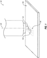
- FIG. 1 illustrates an embodiment of a FBJ system 100 with a FBJ tool 102 in contact with a workpiece 104.
- Rotation of the FBJ tool 102 around a rotational axis 105 in contact with the workpiece 104 may stir the workpiece 104 in a stirred zone 106 and create a heat affected zone 108 beyond the stirred zone 106.
- FBJ stirs a workpiece 104 to refine the grain structure in the stirred zone 106 and/or the heat affected zone 108 of the workpiece material with a consumable FBJ bit.
- the crystalline structural of the workpiece material may be at least partially dependent on the manufacturing of the workpiece.
- the as-manufactured grain structure may be undesirable for a finished part.
- FBJ is may be used to join a plurality of workpieces
- a consumable bit may be used with friction stir processing (FSP) of workpieces.
- FSP friction stir processing
- a cast workpiece has a random orientation (i.e., no texture) with a relatively large grain size with little to no deformation within each grain.
- FSP of the cast aluminum may refine the grain size to produce a smaller average grain size (increasing the boundary density of the microstructure).
- FSP of the cast aluminum may further produce internal strain within the grains. Increases in one or both of the grain boundary density and the internal strain may increase the hardness of the aluminum.
- an extruded or rolled workpiece exhibits a preferred orientation to the grain structure (e.g., a ⁇ 101> texture or a ⁇ 001> texture, respectively in aluminum) that may be undesirable in the finished part.
- a preferred orientation to the grain structure e.g., a ⁇ 101> texture or a ⁇ 001> texture, respectively in aluminum
- an extruded texture in an aluminum rod may increase the mechanical wear rate of the aluminum when used as an axle.
- FSP of the aluminum may mechanically alter the grain structure of the aluminum rod and/or remove the extruded texture of the rod surface.
- Orientation textures may affect other mechanical or chemical properties of the workpiece, such as anisotropic hardness or toughness, or oxidation rates.
- FBJ refers to friction stir welding of a first workpiece to a second workpiece.
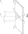
- FIG. 2 illustrates the FBJ system 100 and FBJ tool of FIG. 1 stir welding a butt joint.
- a first workpiece 104-1 may be positioned contacting a second workpiece 104-2 in a butt joint 110, and the first workpiece 104-1 and second workpiece 104-2 may be joined along the butt joint 110 by FBJ.
- the FBJ tool 102 may flow first workpiece material and second workpiece material in a circular direction and perpendicular to the butt joint 110 in the stirred zone 106 to transfer material between the first workpiece 104-1 and second workpiece 104-2, mechanically joining the first workpiece 104-1 and second workpiece 104-2 along the butt joint 110.
- Stir welding is a solid state joining process that plastically moves material of the first workpiece 104-1 and second workpiece 104-2 to interlock the first workpiece 104-1 and second workpiece 104-2 at a microstructural level.
- the first workpiece 104-1 and second workpiece 104-2 are the same material.
- the first workpiece 104-1 and the second workpiece 104-2 may be both a AA 6065 aluminum alloy.
- the first workpiece 104-1 and second workpiece 104-2 are different materials.
- the first workpiece 104-1 may be a single-phase aluminum alloy
- the second workpiece 104-2 may be a single-phase copper alloy.
- the first workpiece 104-1 is an AA 6063 aluminum alloy and the second workpiece 104-2 is an AA 7075 aluminum alloy.
- stir welding by FBJ includes friction stirring of a first workpiece and a second workpiece adjacent one another in a lap joint, such as the embodiment illustrated in FIG. 3-1 .
- the FBJ tool 102 may be positioned contacting a surface of the first workpiece 104-1 and the FBJ tool 102 may be plunged into the first workpiece 104-1 and, optionally, the second workpiece 104-2 to plastically move first workpiece material and second workpiece material to interlock the first workpiece 104-1 and the second workpiece 104-2 at the lap joint 112.
- a lap joint 111 weld by FBJ may require greater axial loads than a butt joint weld.
- the increased axial load may generate greater thermal energy and greater flow of material when a non-cutting FBJ bit is used to displace workpiece material.
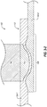
- FIG. 3-2 is a side cross-sectional view of the lap joint 112 of FIG. 3-1 .
- FIG. 4 is a side cross-sectional view of an embodiment of a FBJ tool 102, according to the present disclosure.
- the FBJ tool 102 has a bit 114 coupled to a driver 116.
- the bit 114 may be rotationally fixed relative to the driver 116, such that rotation of the driver 116 by a FBJ system 100 may rotate the FBJ bit 114.
- the bit 114 is axially fixed relative to the driver 116, such that axial movement of the driver 116 produces axial movement of the bit 114.
- the bit 114 may be axially fixed to the driver 116 up to a threshold force. Exceeding the threshold force may disconnect the bit 114 from the driver 116.
- the threshold force may allow the bit 114 to move with the driver 116 to position the FBJ tool 102, and the subsequently for the bit 114 to be left in the workpiece(s) upon completion of the weld.
- the threshold force is greater than 0.5 lbs. (2.22 N). In other embodiments, the threshold force is greater than 1.0 lbs. (4.45 N). In yet other embodiments, the threshold force is greater than 5.0 pounds (22.24 N).
- the threshold force may be the force needed to separate the bit 114 and driver 116, while the axial compression force downward toward the workpieces 104-1, 104-2 may be in a range having an upper value, a lower value, or upper and lower values including any of 1,000 lbs. (4.45 kN), 2,000 lbs. (8.90 kN), 4,000 lbs. (17.8 kN), 6,000 lbs. (26.7 kN), 8,000 lbs. (35.6 kN), 10,000 lbs. (44.5 kN), 15,000 lbs. (66.8 kN), 20,000 lbs. (89.0 kN), greater than 20,000 lbs. (89.0 kN), or any values therebetween.
- the axial force may be greater than 1,000 lbs.
- the axial force may be less than 20,000 lbs. (89.0 kN). In yet other examples, the axial force may be between 1,000 lbs. (4.45 kN) and 20,000 lbs. (89.0 kN). In further examples, the axial force may be between 1,000 lbs. (4.45 kN) and 10,000 lbs. (44.5 kN). In at least one example, the axial force may be between 3,750 lbs. (16.7 kN) and 4,250 lbs. (18.9 kN), and in a particular embodiment is 4,000 lbs. (17.8 kN).
- the bit 114 includes or is made of a ferrous alloy, such as tool steel, a nickel alloy (e.g., a nickel superalloy), an aluminum alloy (e.g., AA 6065), or any other material that is metallurgically compatible with the workpiece to which the FBJ bit 114 is intended to bond.
- a ferrous alloy such as tool steel, a nickel alloy (e.g., a nickel superalloy), an aluminum alloy (e.g., AA 6065), or any other material that is metallurgically compatible with the workpiece to which the FBJ bit 114 is intended to bond.
- the bit 114 may be metallurgically compatible with both workpieces 104-1, 104-2 in a butt joint.
- the bit 114 is metallurgically compatible with the bottom workpiece (i.e., the second workpiece 104-2) in a lap joint 112.
- the bit 114 has one or more coatings to improve the metallurgical compatibility of the bit 114 and the workpiece(s) 104-1,104-2. In other embodiments, the bit 114 has one or more coatings to improve the erosion and/or wear resistance of the bit 114. In yet other embodiments, the bit 114 has one or more coatings to improve the corrosion resistance of the bit 114.
- the displacement of workpiece material from the workpieces 104-1, 104-2 at the lap joint 112 disturbs and flow workpiece material within the stirred zone 106 even before any rotation of the bit 114 and stirring of the workpiece material.
- penetration of the bit 114 by displacement in contrast to cutting, may allow for greater total movement of workpiece material, increasing the homogeneity and strength of the resulting welds.
- the threshold force may be at least partially related to an attachment mechanism of the bit 114 to the driver 116.
- FIG. 4 is an exploded perspective view of the embodiment of a bit 114 and driver 116 of FIG 3-1 showing an attachment mechanism therebetween.
- a bit 114 is configured to rotate about a rotational axis 105 to move workpiece material.
- the bit 114 may have a pin 118 and a shoulder 120.
- the pin 118 may facilitate penetration into the workpiece material and subsequent stirring of the workpiece material.
- the shoulder 120 may be wider than the pin 118 and may contain the workpiece material displaced by the pin 118 and further facilitate stirring of the workpiece material.
- the bit 114 has a pin 118 but lacks a shoulder 120.
- the driver 116 may include a driver body 122 and one or more mechanical interlocking features 124 that allow the driver 116 to interlock and engage with complementary interlocking features 126 on the bit 114.
- the mechanical interlocking features 124 may be protrusions or posts that engage with recesses or other complementary interlocking features 126 on the bit 114.
- the complementary interlocking features 126 on the bit 114 are protrusions or posts that engage with recesses or other mechanical interlocking features 124 on the driver 116.
- an extra finishing step may be performed to remove the raised complementary interlocking features 126 and create a planar surface after the FBJ process is complete.
- the driver 116 includes cutters 128 to remove flash or other debris during the FBJ process.
- the cutters 128 may be coupled to the driver body 122 such that the cutters rotate about the rotational axis 105 as the driver 116 turns.
- the cutters 128 may be positioned to cut material from the workpiece and produce a substantially flat surface after FBJ.
- the FBJ system includes an evacuation and/or collection system for the cuttings produced by the cutters 128 removing flash or other workpiece material.
- the evacuation and/or collection system may include a vacuum system and/or a waste collection bin to collect and ease disposal or reuse of the cuttings.
- the cutters 128 are used to determine a depth of penetration of the bit 114 into a workpiece.
- the driver 116 may cease axial movement, and the associated axial penetration of the bit 114, when the cutters 128 contact that workpiece surface.
- a cutting edge of the cutter 128 is positioned axially even with a top surface of the bit 114 to limit penetration of the bit 114 and driver 116 into the workpiece material.
- the driver body 122 supports one or more burnishers, polishers, or smoothing elements that do not cut, but otherwise contact a surface of the workpiece as the driver 116 rotates about the rotational axis 105.
- the burnishers or smoothing elements are used to determine a depth of penetration of the bit 114 into a workpiece.
- FIG. 5 is an end view of embodiment of a driver 116 of FIG. 4 .
- the driver 116 may include a plurality of mechanical interlocking features 124.
- the mechanical interlocking features 124 are positioned at angular intervals around the rotational axis 105.
- the mechanical interlocking features 124 may be positioned at equal angular intervals around the rotational axis.
- a driver 116 with three mechanical interlocking features 124 has the mechanical interlocking features 124 positioned at 120° angular intervals.
- a driver 116 with two mechanical interlocking features 124 may have the mechanical interlocking features 124 positioned at 180° intervals.
- the driver 116 has 4, 5, 6, 7, 8, or more mechanical interlocking features 124.
- the driver 116 has mechanical interlocking features 124 that are positioned at unequal intervals.
- a driver 116 with three mechanical interlocking features 124 may have the mechanical interlocking features 124 positioned at 110°, 120°, and 130°, angular intervals from one another.
- a driver 116 with two mechanical interlocking features 124 may have the mechanical interlocking features 124 positioned at 170° and 190° intervals.
- the driver 116 may include a plurality of cutters 128 oriented in the rotational direction 132 of the driver 116.
- the cutters 128 may include or be made of hard materials, such as tool steel or cobalt-chromium alloys; a carbide, such as tungsten carbide; other superhard materials, such as diamond or polycrystalline cubic boron nitride; or other materials.
- the cutters 128 are positioned at regular angular intervals around the rotational axis 105.
- the cutters 128 may be positioned at equal angular intervals around the rotational axis.
- a driver 116 with three cutters 128 has the cutters 128 positioned at 120° angular intervals.
- a driver 116 with two cutters 128 may have the cutters 128 positioned at 180° intervals.
- the driver 116 has 4, 5, 6, 7, 8, or more cutters 128.
- the driver 116 has cutters 128 that are positioned at unequal intervals.
- a driver 116 with three cutters 128 may have the cutters 128 positioned at 110°, 120°, and 130° angular intervals from one another, or at 110°, 110°, 140° angular intervals from one another.
- a driver 116 with two cutters 128 may have the cutters 128 positioned at 170° and 190° intervals or at 150° and 210° intervals.
- the mechanical interlocking features 124 has a friction fit with the complementary interlocking features 126 of the bit 114, shown in FIG. 6 , in addition to transmitting torque from the driver 116 to the bit 114.
- the axial connection of the bit 114 and the driver 116 is at least partially due to the friction fit between one or more of the mechanical interlocking features 124 and the complementary interlocking features 126.
- the driver 116 includes a retention mechanism to retain the bit 114 against the driver 116.
- the driver 116 may include a magnet 134 in the driver 116 that applies a magnetic force to the bit 114 to retain the bit 114 against the driver 116 and engaged with the mechanical interlocking features 124.
- the magnet 134 is an electromagnet that may be disabled to release the bit 114 in the axial direction.
- a magnet 134 is thermally insulated to protect the magnet 134 from thermal damage during the FBJ process.
- the retention mechanism includes a vacuum retention system that retains the bit 114 against the driver 116.
- FIG. 6 is a top view of the embodiment of a bit 114 of FIG. 4 facing a top surface 140 opposite the pin illustrated in FIG. 4 .
- the bit 114 may be configured to rotate about the rotational axis 105.
- the complementary interlocking features 126 may be positioned at angular intervals around the rotational axis 105.
- the angular positions of the complementary interlocking features 126 may be selected to match the positions of the mechanical interlocking features of the driver, as describe in relation to FIG. 5 .
- a bit 114 includes a magnet 138 that is positioned to apply a magnetic force to the driver to retain the bit 114 on the driver.
- a bit 114 has no magnet, but includes or is made of a magnetic (such as ferromagnetic) material.
- a magnet positioned on the driver may apply a magnetic field to the bit 114, producing a magnetic force that retains the bit 114 on the driver 116.
- the magnet 138 may be flush with a top surface 140 of the bit 114, such that the bit 114 presents a flat top surface 140 when consumed in a joint during the FBJ process.
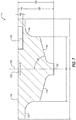
- the magnet 138 and complementary interlocking features 126 of the bit 114 are illustrated in a side cross-sectional view of the bit 114 in FIG. 7 .
- the complementary interlocking features 126 may have an interlock depth 142 from the top surface 140 that is relative to a shoulder height 144 of the shoulder 120 of the bit 114.
- the interlock depth 142 is a percentage of the shoulder height 144 in a range having an upper value, a lower value, or upper and lower values including any of 50%, 60%, 70%, 80%, 90%, 100%, greater than 100%, or any values therebetween.
- the interlock depth 142 may be greater than 50% of the shoulder height 144. In other examples, the interlock depth 142 may be less than 100% of the shoulder height 144.
- the interlock depth 142 may be between 50% and 100% of the shoulder height 144. In further examples, the interlock depth 142 may be between 60% and 90% of the shoulder height 144. In at least one example, the interlock depth 142 may be greater than 100% of the shoulder height 144.
- FIG. 7 illustrates an embodiment of a bit 114 with a planar top surface 140
- a bit 114 may have a top surface 140 that is convex, similar to a truss head on a bolt.
- a top surface 140 may be concave, such that a portion of the top surface 140 is recessed toward the pin 118 of the bit 114.
- the top surface 140 may be frustoconical with a portion that is planar and a portion that is non-planar.
- the bit 114 has a generally conical pin 118 and substantially flat shoulder 120.
- a curved transition 146 may be positioned between the pin 118 and the adjacent shoulder 120 to direct workpiece material flow to the shoulder 120.
- the bit 114 has a pin 118 and lacks a shoulder 120.
- the pin 118 has a face 148 with one or more surface features thereon to engage with the workpiece material and increase flow of the workpiece material around the bit 114.
- a pin 118 includes one or more surface features to increase the movement of workpiece material during rotation of the pin 118.
- a pin 118 may have a spiral surface feature to urge material in the stirred zone to circulate toward the radial center of the stirred zone instead of displacing radially away from the FBJ bit 114.
- Such a pin surface feature may be beneficial in a lap joint friction stir weld to reduce and/or prevent thinning of the workpiece material in the weld zone.
- the spiral pin surface feature in combination with the angle of a linear portion and/or curved portion of the pin profile, may circulate workpiece material downward toward within the stirred region, as well.
- Such a surface feature may be beneficial in a lap friction stir weld to encourage stirred workpiece material from the first workpiece toward the second workpiece to form the lap joint.
- the pin 118 in FIG. 7 has a pin height 150 that is relative to the shoulder height 144.
- the pin height 150 is a percentage of the shoulder height 144 in a range having an upper value, a lower value, or upper and lower values including any of 50%, 60%, 70%, 80%, 90%, 100%, 110%, 120%, 130%, 140%, 150%, greater than 150%, or any values therebetween.
- the pin height 150 may be greater than 50% of the shoulder height 144.
- the pin height 150 may be less than 150% of the shoulder height 144.
- the pin height 150 may be between 50% and 150% of the shoulder height 144.
- the pin height 150 may be between 75% and 125% of the shoulder height 144.
- the interlock depth 142 may be greater than 150% of the shoulder height 144.
- the pin 118 has a pin height 150 that is relative to a bit height 136.
- the pin height 150 may be in a range having an upper value, a lower value, or an upper and lower value including any of 5%, 10%, 15%, 20%, 25%, 30%, 40%, 45%, 50%, 60%, 70%, 80%, 90%, 100% of the bit height 136, or any values therebetween.
- the pin height 150 may be greater than 10% of the bit height 136.
- the pin height 150 may be greater than 25% of the bit height 136.
- the pin height 150 may be greater than 50% of the bit height 136.
- the pin 118 has a pin height 150 in the longitudinal direction that is relative to a total diameter 154 of the bit 114.
- the total diameter 154 is a maximum diameter of the bit 114, or the diameter of the top surface 140.
- the pin height 150 may be in a range having an upper value, a lower value, or an upper and lower value including any of 5%, 10%, 15%, 20%, 25%, 30%, 40%, 45%, 50%, 60%, 70%, 80%, 90%, 100% of the total diameter 154, or any values therebetween.
- the pin height 150 may be greater than 5% of the total diameter 154.
- the pin height 150 may be less than 100% of the total diameter 154.
- the pin height 150 may be between 10% and 50% of the total diameter 154.
- the pin height 150 may be between 15% and 35% of the total diameter 154.
- the bit 114 has a bit height 136 that is related to the total diameter 154.
- the bit height 136 may be in a range having an upper value, a lower value, or an upper and lower value including any of 5%, 10%, 15%, 20%, 25%, 30%, 40%, 45%, 50%, 60%, 70%, 80%, 90%, 100% of the total diameter 154, or any values therebetween.
- the bit height 136 may be greater than 5% of the total diameter 154.
- the bit height 136 may be less than 100% of the total diameter 154.
- the bit height 136 may be between 10% and 50% of the total diameter 154.
- the bit height 136 may be between 25% and 40% of the total diameter 154.
- the bit height 136 may be greater than 100% of the total diameter 154, such as when joining thick workpieces and/or the site of the FBJ placement has relatively small lateral clearance.
- FIG. 7 illustrates a bit 114 with a tapered pin 118.
- the pin 118 has a pin profile that is at least partially linear.
- the pin 118 has a pin profile that is at least partially curved.
- the pin 118 has a pin profile with a portion that is curved and a portion that is linear.
- the embodiment of a pin 118 illustrated in FIG. 7 includes a pin profile with a curved transition 146 and a linear face 148.
- the bit 114 may have a non-cutting tip 152 that allows the bit 114 to penetrate a workpiece by displacing workpiece material without cutting the workpiece material.
- the bit 114 has a tip 152 that is rounded.
- the tip 152 may be pointed.
- the tip 152 is planar and the face 148 is optionally angled, such that the pin 118 is frustoconical.
- the tip 152 is planar across a pin diameter 156, such that the pin 118 is substantially cylindrical.
- the tip 152 includes at least one pilot feature to assist in engaging with and penetrating into the workpiece material.
- the tip 152 is a cutting tip that includes one or more cutting features to accelerate penetration into the workpiece material.
- the cutting features may cut a pilot hole with a diameter less than a pin diameter 156, such that the pin 118 displaces workpiece material radially outside the pilot hole.
- the cutting features may cut a pilot hole with a diameter 50% of the pin diameter 156, and the face 148 of the pin 118 may displace workpiece material outside of the pilot hole.
- the pin 118 has a pin diameter 156 that is related to the total diameter 154 of the bit 114.
- the pin diameter 156 may be a percentage of the total diameter 154 in a range having an upper value, a lower value, or an upper and lower value including any of 5%, 10%, 15%, 20%, 25%, 30%, 40%, 45%, 50%, 60%, 70%, 80%, 90%, 100%, or any values therebetween.
- the pin diameter 156 may be greater than 5% of the total diameter 154.
- the pin diameter 156 may be less than 100% of the total diameter 154.
- the pin diameter 156 may be between 10% and 90% of the total diameter 154.
- the pin diameter 156 may be between 25% and 75% of the total diameter 154.
- the pin 118 has a face angle 158 between a face 148 of the pin 118 and the rotational axis 105 that is in a range having an upper value, a lower value, or upper and lower values including any of 30°, 40°, 45°, 50°, 60°, 75°, 80°, 85°, 90°, or any values therebetween.
- a face 148 may be oriented at a face angle 158 greater than 30°.
- the face 148 is oriented at a face angle 158 less than 90°.
- the face 148 is oriented a face angle 158 between 30° and 90°.
- the face 148 is oriented at a face angle 158 between 45° and 80°.
- the face 148 is oriented at a face angle 158 of 60° to the rotational axis 105. In at least another example, the face 148 is oriented at a face angle 158 that is non-perpendicular to the rotational axis 105.
- FIG. 8 is a perspective view of an embodiment of a lap joint 112 after welding a first workpiece 104-1 to a second workpiece 104-2 via FBJ.
- a bit 114 is consumed in the lap joint 112.
- the bit 114 may be left in the lap joint 112 flush with a workpiece surface 160 such that the top surface 140, stirred zone 106, and the workpiece surface 160 are continuous and/or planar with one another.
- the bit 114 is considered flush with the workpiece surface even if a portion of the bit 114 protrudes from the workpiece surface 160.
- the bit 114 may protrude from the workpiece surface 160 no more than 5.0 millimeters.
- the bit 114 protrudes from the workpiece surface 160 no more than 3.0 mm.
- the bit 114 protrudes from the workpiece surface 160 no more than 1.0 mm.
- the top surface 140 of the bit 114 is recessed into the workpiece 104-1, 104-2 such that a portion of the top surface 140 is below the workpiece surface 160.
- the top surface 140 may be recessed no more than 5.0 mm.
- the top surface 140 is recessed no more than 3.0 mm.
- the top surface 140 is recessed no more than 1.0 mm.
- the stirred zone 106 of the lap joint 112 includes a finished area 162, or is surrounded by the finished area 162.
- the finished area 162 may be the region of the lap joint contacted by the cutters and/or smoothing elements of the driver during the FBJ process.
- the cutters such as cutters 128 illustrated in FIG. 4
- the cutters may be positioned radially outside of the bit 114 relative to a rotational axis of the FBJ tool. The cutters may, therefore interact with the workpiece surface 160 radially outside of the stirred zone 106 generated by the contact of the bit 114.
- the finished area 162 includes a cut surface where flash or other workpiece material displaced during the FBJ process is removed from the workpiece surface 160.
- the finished area 162 includes a burnished surface that is burnished or otherwise smoothed by smoothing elements without cutting the workpiece material adjacent the stirred zone 106.
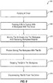
- FIG. 9 is a flowchart illustrating an embodiment of a method 264 of friction stirring a workpiece with a FBJ tool.
- the method 264 may include rotating a driver at 266 and rotating a bit with the driver in contact with a workpiece at 268.
- the driver and bit rotate at a rotational speed in a range having an upper value, a lower value, or upper and lower values including any of 1 rpm, 50 rpm, 100 rpm, 1,000 rpm, 5,000 rpm, 10,000 rpm, 20,000 rpm, 40,000 rpm, 60,000 rpm, greater than 60,000 rpm, or any values therebetween.
- the rotational speed of the driver and bit may be greater than 1 rpm.
- the rotational speed of the driver and bit is less than 60,000 rpm. In yet other examples, the rotational speed is between 1 rpm and 60,000 rpm. In further examples, the rotational speed is between 50 rpm and 20,000 rpm. In at least one example, the rotational speed is between 100 rpm and 10,000 rpm.
- the method 264 further includes moving the bit axially into the workpiece and displacing workpiece material at 270. Plunging the bit into the workpiece may displace material before or after the rotation of the bit generates thermal energy. In some examples, the deformation of the workpiece material by the axial movement of the bit and the associated displacement of the workpiece material generates thermal energy to soften and/or plasticize the workpiece material for FBJ.
- the method 264 may include friction stirring the workpiece with the bit at 272 and then stopping the bit in the workpiece at 274 to bond the bit to the workpiece material in the stirred zone.
- friction stirring the workpiece includes removing flash from the workpiece as workpiece material is displaced by the bit.
- the flash may be removed by one or more cutters on the driver that rotate about a shared rotational axis withe the driver.
- the bit is stopped from the rotational speed of friction stirring in under 3.0 seconds. In other embodiments, the bit is stopped from the rotational speed of friction stirring in under 1.0 seconds. In yet other embodiments, the bit is stopped from the rotational speed of friction stirring in under 0.5 seconds. In further embodiments, the bit is stopped from the rotational speed of friction stirring in under 0.1 seconds.
- the method 264 includes disconnecting the bit from the driver at 276 after stopping the bit. For example, upon stopping the bit in the workpiece, the bit may become bonded to the workpiece material and moving the driver axially away from the workpiece may disconnect the driver from the bit. In some embodiments, disconnecting the bit from the driver includes exceeding a threshold force to disconnect the bit from the driver. In at least one embodiment, disconnecting the bit from the driver includes disabling an electromagnet in the driver to remove a magnetic force from the bit.
- a FBJ system may allow the friction stirring of a workpiece with a consumable bit while increasing workpiece material flow by displacing workpiece material upon penetration of the bit.
- a bit according to the present disclosure provides a flush surface with the workpiece surface without additional finishing steps after the FBJ process is completed.
- Numbers, percentages, ratios, or other values stated herein are intended to include that value, and also other values that are “about” or “approximately” the stated value, as would be appreciated by one of ordinary skill in the art encompassed by embodiments of the present disclosure.
- a stated value should therefore be interpreted broadly enough to encompass values that are at least close enough to the stated value to perform a desired function or achieve a desired result.
- the stated values include at least the variation to be expected in a suitable manufacturing or production process.
- any references to “up” and “down” or “above” or “below” are merely descriptive of the relative position or movement of the related elements.
Landscapes
- Engineering & Computer Science (AREA)
- Mechanical Engineering (AREA)
- Pressure Welding/Diffusion-Bonding (AREA)
- Drilling Tools (AREA)
Abstract
Description
- Friction stir processing ("FSP") of metals has been used to attach weldable materials to one another in a solid state joining process. FSP uses the motion of a pin pressed against the surface of a weldable material to generate heat and friction to move the weldable material. The material can plasticize and physically stir together with a second material to which the first material is joined. A pin, a pin and shoulder, or another "FSP tool" may be rotated in contact with a workpiece. A force is applied to the FSP tip to urge the FSP tool against the workpiece. The FSP tool is moved along the workpiece to stir the material of the workpiece. The physical process of mixing material from two plates joins the plates.
- FSP joins weldable materials in a solid-state process that avoids many of the potential defects of other welding processes. For example, FSP produces a stirred region along the path of the tool that is generally indistinguishable from the original material. FSP may be performed without the inclusion of an additional material or use of shield gasses. Some welding methods, such as metal-inert gas ("MIG") welding, may introduce an additional material to create a bond. Other welding methods, such as tungsten-inert gas ("TIG") welding, may use a non-consumable contact point to heat one or more workpieces. However, the heating may cause the one or more workpieces to attain a liquid phase and risk a phase change in the one or more workpieces. A phase change may compromise the integrity of the bond and, potentially, the workpiece, itself. To limit the possibility of a phase change or other reaction, TIG welding and similar processes utilize an inert gas "shield" around the contact area.
- Conventional FSP uses a non-consumable bit and leaves a void when the FSP tool is retracted from the workpiece. Friction bit joining (FBJ) uses a consumable bit that is consumed by the FBJ process and become an integral part of the joint produced. A FBJ joint typically requires at least one finishing step and sometimes more to produce a finished surface.
- In some embodiments, a tool for friction bit joining a workpiece material includes a bit with a pin that is tapered and has a non-cutting tip. The bit has a top surface opposite the pin with at least one feature recessed in the top surface configured to transmit torque to the bit to rotate the bit around a rotational axis.
- In some embodiments, a tool for friction bit joining includes a bit and a driver. The driver has a driver body rotatable around a rotational axis and at least one mechanical interlocking feature protruding from the driver body. The bit has a top surface opposite the pin with at least one complementary interlocking feature recessed in the top surface configured to transmit torque to the bit to rotate the bit around the rotational axis.
- In some embodiments, a method of friction bit joining a workpiece includes rotating a driver around a rotational axis and rotating a bit in contact with the workpiece using the driver. The method further includes moving the bit axially into the workpiece and displacing workpiece material. The method continues by friction stirring the workpiece material with the bit with a top surface of the bit flush with a workpiece surface and then stopping the bit in the workpiece and disconnecting the bit from the driver such that the bit remains in the workpiece.
- This summary is provided to introduce a selection of concepts that are further described below in the detailed description. This summary is not intended to identify key or essential features of the claimed subject matter, nor is it intended to be used as an aid in limiting the scope of the claimed subject matter.
- Additional features and advantages of embodiments of the disclosure will be set forth in the description which follows, and in part will be obvious from the description, or may be learned by the practice of such embodiments. The features and advantages of such embodiments may be realized and obtained by means of the instruments and combinations particularly pointed out in the appended claims. These and other features will become more fully apparent from the following description and appended claims, or may be learned by the practice of such embodiments as set forth hereinafter.
- In order to describe the manner in which the above-recited and other features of the disclosure can be obtained, a more particular description will be rendered by reference to specific embodiments thereof which are illustrated in the appended drawings. For better understanding, the like elements have been designated by like reference numbers throughout the various accompanying figures. While some of the drawings may be schematic or exaggerated representations of concepts, other drawings should be considered as drawn to scale for example embodiments. Understanding that the drawings depict some example embodiments, the embodiments will be described and explained with additional specificity and detail through the use of the accompanying drawings in which:
-
FIG. 1 is a perspective view of a friction bit joining system, according to some embodiments of the present disclosure; -
FIG. 2 is a is a perspective view of a friction bit joining system welding a butt joint, according to some embodiments of the present disclosure; -
FIG. 3-1 is a perspective view of a friction bit joining system welding a lap joint, according to some embodiments of the present disclosure; -
FIG. 3-2 is a side cross-sectional view of the embodiment of a lap joint illustrated inFIG. 3-1 ; -
FIG. 4 is a perspective exploded view of the embodiment of a friction bit joining tool ofFIG. 3-1 ; -
FIG. 5 is an end view of the embodiment of a friction bit driver ofFIG. 3-1 ; -
FIG. 6 is an end view of the embodiment of a friction bit ofFIG. 3-1 ; -
FIG. 7 is a side cross-sectional view of the embodiment of a friction bit ofFIG. 3-1 ; -
FIG. 8 is a perspective view of a friction bit joining joint, according to some embodiments of the present disclosure; and -
FIG. 9 is a flowchart illustrating a method of friction bit joining workpieces, according to some embodiments of the present disclosure. - This disclosure generally relates to devices, systems, and methods for increasing efficiency of a friction bit joining (FBJ) tool for friction stir welding, joining, processing, or other friction stirring procedures. More specifically, some of the embodiments described herein relate to the design, manufacture, and use of FBJ tools that produce a near-finished surface during the FBJ process. For example, a FBJ tool may be used to friction stir one or more workpieces and consume the FBJ bit in the joint while leaving a surface that is flush with the original workpiece surface and free of flash or other debris without the need for subsequent machine or finishing procedures.
- In some embodiments, a FBJ tool according to the present disclosure includes a FBJ bit and a FBJ driver. The FBJ bit may be rotated by the driver through a mechanical interlock between the FBJ bit and driver to friction stir a workpiece or workpieces. The FBJ bit may, subsequently, remain in the joint with a surface of the FBJ bit flush with a surface of the workpiece when the driver is retracted.
- In some embodiments, the FBJ bit has a conical (including frusto-conical), curved, or other non-cutting tip. The tip of the FBJ bit may be plunged into a workpiece with an axial force that displaces workpiece material from the stirred region of the workpiece and/or joint. In some embodiments, a driver of the FBJ tool includes one or more cutting elements to cut or otherwise remove flash from the surface of the workpiece around the stirred region. In other embodiments, the driver includes one or more burnishers to compress and/or burnish a surface of the workpiece around the stirred region.
- In some embodiments, the penetration of the FBJ bit by displacement of workpiece material instead of cutting into the workpiece material may produce greater amounts of movement of the workpiece material. In some examples, the FBJ tool may produce thermal energy upon displacement in addition to the rotation of the FBJ tool in contact with the workpiece. The FBJ tool may then frictionally drag the workpiece material to flow the workpiece material in substantially circular motion with the rotation of the FSP tool work surface. In other examples, the FBJ tool includes one or more surface features on a pin and/or a shoulder that mechanically engage with the workpiece material to flow the workpiece material. The increased flow rate may produce a stronger weld and/or allow increased translational speeds across the workpiece surface to complete a weld in less time.
-
FIG. 1 illustrates an embodiment of aFBJ system 100 with aFBJ tool 102 in contact with a workpiece 104. Rotation of theFBJ tool 102 around arotational axis 105 in contact with the workpiece 104 may stir the workpiece 104 in a stirredzone 106 and create a heat affectedzone 108 beyond the stirredzone 106. In some embodiments, FBJ stirs a workpiece 104 to refine the grain structure in the stirredzone 106 and/or the heat affectedzone 108 of the workpiece material with a consumable FBJ bit. For example, the crystalline structural of the workpiece material may be at least partially dependent on the manufacturing of the workpiece. The as-manufactured grain structure may be undesirable for a finished part. While FBJ is may be used to join a plurality of workpieces, a consumable bit may be used with friction stir processing (FSP) of workpieces. - In some examples, a cast workpiece has a random orientation (i.e., no texture) with a relatively large grain size with little to no deformation within each grain. FSP of the cast aluminum may refine the grain size to produce a smaller average grain size (increasing the boundary density of the microstructure). FSP of the cast aluminum may further produce internal strain within the grains. Increases in one or both of the grain boundary density and the internal strain may increase the hardness of the aluminum.
- In other examples, an extruded or rolled workpiece exhibits a preferred orientation to the grain structure (e.g., a <101> texture or a <001> texture, respectively in aluminum) that may be undesirable in the finished part. For example, an extruded texture in an aluminum rod may increase the mechanical wear rate of the aluminum when used as an axle. FSP of the aluminum may mechanically alter the grain structure of the aluminum rod and/or remove the extruded texture of the rod surface. Orientation textures may affect other mechanical or chemical properties of the workpiece, such as anisotropic hardness or toughness, or oxidation rates.
- In other embodiments, FBJ refers to friction stir welding of a first workpiece to a second workpiece. For example,
FIG. 2 illustrates theFBJ system 100 and FBJ tool ofFIG. 1 stir welding a butt joint. A first workpiece 104-1 may be positioned contacting a second workpiece 104-2 in a butt joint 110, and the first workpiece 104-1 and second workpiece 104-2 may be joined along the butt joint 110 by FBJ. TheFBJ tool 102 may flow first workpiece material and second workpiece material in a circular direction and perpendicular to the butt joint 110 in the stirredzone 106 to transfer material between the first workpiece 104-1 and second workpiece 104-2, mechanically joining the first workpiece 104-1 and second workpiece 104-2 along thebutt joint 110. - Stir welding is a solid state joining process that plastically moves material of the first workpiece 104-1 and second workpiece 104-2 to interlock the first workpiece 104-1 and second workpiece 104-2 at a microstructural level. In some embodiments, the first workpiece 104-1 and second workpiece 104-2 are the same material. For example, the first workpiece 104-1 and the second workpiece 104-2 may be both a AA 6065 aluminum alloy. In other embodiments, the first workpiece 104-1 and second workpiece 104-2 are different materials. For example, the first workpiece 104-1 may be a single-phase aluminum alloy, and the second workpiece 104-2 may be a single-phase copper alloy. In other examples, the first workpiece 104-1 is an AA 6063 aluminum alloy and the second workpiece 104-2 is an AA 7075 aluminum alloy.
- In yet another embodiment, stir welding by FBJ includes friction stirring of a first workpiece and a second workpiece adjacent one another in a lap joint, such as the embodiment illustrated in
FIG. 3-1 . TheFBJ tool 102 may be positioned contacting a surface of the first workpiece 104-1 and theFBJ tool 102 may be plunged into the first workpiece 104-1 and, optionally, the second workpiece 104-2 to plastically move first workpiece material and second workpiece material to interlock the first workpiece 104-1 and the second workpiece 104-2 at thelap joint 112. - In some embodiments, a lap joint 111 weld by FBJ may require greater axial loads than a butt joint weld. The increased axial load may generate greater thermal energy and greater flow of material when a non-cutting FBJ bit is used to displace workpiece material. For example,
FIG. 3-2 is a side cross-sectional view of thelap joint 112 ofFIG. 3-1 . -
FIG. 4 is a side cross-sectional view of an embodiment of aFBJ tool 102, according to the present disclosure. In some embodiments, theFBJ tool 102 has abit 114 coupled to adriver 116. Thebit 114 may be rotationally fixed relative to thedriver 116, such that rotation of thedriver 116 by aFBJ system 100 may rotate theFBJ bit 114. In other embodiments, thebit 114 is axially fixed relative to thedriver 116, such that axial movement of thedriver 116 produces axial movement of thebit 114. For example, thebit 114 may be axially fixed to thedriver 116 up to a threshold force. Exceeding the threshold force may disconnect thebit 114 from thedriver 116. The threshold force may allow thebit 114 to move with thedriver 116 to position theFBJ tool 102, and the subsequently for thebit 114 to be left in the workpiece(s) upon completion of the weld. In some embodiments, the threshold force is greater than 0.5 lbs. (2.22 N). In other embodiments, the threshold force is greater than 1.0 lbs. (4.45 N). In yet other embodiments, the threshold force is greater than 5.0 pounds (22.24 N). - The threshold force may be the force needed to separate the
bit 114 anddriver 116, while the axial compression force downward toward the workpieces 104-1, 104-2 may be in a range having an upper value, a lower value, or upper and lower values including any of 1,000 lbs. (4.45 kN), 2,000 lbs. (8.90 kN), 4,000 lbs. (17.8 kN), 6,000 lbs. (26.7 kN), 8,000 lbs. (35.6 kN), 10,000 lbs. (44.5 kN), 15,000 lbs. (66.8 kN), 20,000 lbs. (89.0 kN), greater than 20,000 lbs. (89.0 kN), or any values therebetween. For example, the axial force may be greater than 1,000 lbs. (4.45 kN). In other examples, the axial force may be less than 20,000 lbs. (89.0 kN). In yet other examples, the axial force may be between 1,000 lbs. (4.45 kN) and 20,000 lbs. (89.0 kN). In further examples, the axial force may be between 1,000 lbs. (4.45 kN) and 10,000 lbs. (44.5 kN). In at least one example, the axial force may be between 3,750 lbs. (16.7 kN) and 4,250 lbs. (18.9 kN), and in a particular embodiment is 4,000 lbs. (17.8 kN). - In some embodiments, the
bit 114 includes or is made of a ferrous alloy, such as tool steel, a nickel alloy (e.g., a nickel superalloy), an aluminum alloy (e.g., AA 6065), or any other material that is metallurgically compatible with the workpiece to which theFBJ bit 114 is intended to bond. For example, thebit 114 may be metallurgically compatible with both workpieces 104-1, 104-2 in a butt joint. In other examples, thebit 114 is metallurgically compatible with the bottom workpiece (i.e., the second workpiece 104-2) in alap joint 112. In some embodiments, thebit 114 has one or more coatings to improve the metallurgical compatibility of thebit 114 and the workpiece(s) 104-1,104-2. In other embodiments, thebit 114 has one or more coatings to improve the erosion and/or wear resistance of thebit 114. In yet other embodiments, thebit 114 has one or more coatings to improve the corrosion resistance of thebit 114. - In some embodiments, the displacement of workpiece material from the workpieces 104-1, 104-2 at the lap joint 112 disturbs and flow workpiece material within the stirred
zone 106 even before any rotation of thebit 114 and stirring of the workpiece material. Hence, penetration of thebit 114 by displacement, in contrast to cutting, may allow for greater total movement of workpiece material, increasing the homogeneity and strength of the resulting welds. - The threshold force may be at least partially related to an attachment mechanism of the
bit 114 to thedriver 116. For example,FIG. 4 is an exploded perspective view of the embodiment of abit 114 anddriver 116 ofFIG 3-1 showing an attachment mechanism therebetween. - In some embodiments, a
bit 114 is configured to rotate about arotational axis 105 to move workpiece material. Thebit 114 may have apin 118 and ashoulder 120. For example, thepin 118 may facilitate penetration into the workpiece material and subsequent stirring of the workpiece material. Theshoulder 120 may be wider than thepin 118 and may contain the workpiece material displaced by thepin 118 and further facilitate stirring of the workpiece material. In other embodiments, thebit 114 has apin 118 but lacks ashoulder 120. - The
driver 116 may include adriver body 122 and one or more mechanical interlocking features 124 that allow thedriver 116 to interlock and engage with complementary interlocking features 126 on thebit 114. For example, the mechanical interlocking features 124 may be protrusions or posts that engage with recesses or other complementary interlocking features 126 on thebit 114. In other examples, the complementary interlocking features 126 on thebit 114 are protrusions or posts that engage with recesses or other mechanical interlocking features 124 on thedriver 116. In embodiments with protrusions or other raised complementary interlocking features 126 on thebit 114, an extra finishing step may be performed to remove the raised complementary interlocking features 126 and create a planar surface after the FBJ process is complete. - In some embodiments, the
driver 116 includescutters 128 to remove flash or other debris during the FBJ process. For example, thecutters 128 may be coupled to thedriver body 122 such that the cutters rotate about therotational axis 105 as thedriver 116 turns. Thecutters 128 may be positioned to cut material from the workpiece and produce a substantially flat surface after FBJ. In other embodiments, the FBJ system includes an evacuation and/or collection system for the cuttings produced by thecutters 128 removing flash or other workpiece material. For example, the evacuation and/or collection system may include a vacuum system and/or a waste collection bin to collect and ease disposal or reuse of the cuttings. - In other embodiments, the
cutters 128 are used to determine a depth of penetration of thebit 114 into a workpiece. For example, thedriver 116 may cease axial movement, and the associated axial penetration of thebit 114, when thecutters 128 contact that workpiece surface. In other examples, a cutting edge of thecutter 128 is positioned axially even with a top surface of thebit 114 to limit penetration of thebit 114 anddriver 116 into the workpiece material. In other embodiments, thedriver body 122 supports one or more burnishers, polishers, or smoothing elements that do not cut, but otherwise contact a surface of the workpiece as thedriver 116 rotates about therotational axis 105. In some examples, the burnishers or smoothing elements are used to determine a depth of penetration of thebit 114 into a workpiece. -
FIG. 5 is an end view of embodiment of adriver 116 ofFIG. 4 . As described in relation toFIG. 4 , thedriver 116 may include a plurality of mechanical interlocking features 124. In some embodiments, the mechanical interlocking features 124 are positioned at angular intervals around therotational axis 105. For example, the mechanical interlocking features 124 may be positioned at equal angular intervals around the rotational axis. In some examples, adriver 116 with three mechanical interlocking features 124 has the mechanical interlocking features 124 positioned at 120° angular intervals. Adriver 116 with two mechanical interlocking features 124 may have the mechanical interlocking features 124 positioned at 180° intervals. In other examples, thedriver 116 has 4, 5, 6, 7, 8, or more mechanical interlocking features 124. - In other embodiments, the
driver 116 has mechanical interlocking features 124 that are positioned at unequal intervals. For example, adriver 116 with three mechanical interlocking features 124 may have the mechanical interlocking features 124 positioned at 110°, 120°, and 130°, angular intervals from one another. Adriver 116 with two mechanical interlocking features 124 may have the mechanical interlocking features 124 positioned at 170° and 190° intervals. - As described in relation to
FIG. 4 , thedriver 116 may include a plurality ofcutters 128 oriented in therotational direction 132 of thedriver 116. Thecutters 128 may include or be made of hard materials, such as tool steel or cobalt-chromium alloys; a carbide, such as tungsten carbide; other superhard materials, such as diamond or polycrystalline cubic boron nitride; or other materials. - In some embodiments, the
cutters 128 are positioned at regular angular intervals around therotational axis 105. For example, thecutters 128 may be positioned at equal angular intervals around the rotational axis. In some examples, adriver 116 with threecutters 128 has thecutters 128 positioned at 120° angular intervals. Adriver 116 with twocutters 128 may have thecutters 128 positioned at 180° intervals. In other examples, thedriver 116 has 4, 5, 6, 7, 8, ormore cutters 128. - In other embodiments, the
driver 116 hascutters 128 that are positioned at unequal intervals. For example, adriver 116 with threecutters 128 may have thecutters 128 positioned at 110°, 120°, and 130° angular intervals from one another, or at 110°, 110°, 140° angular intervals from one another. Adriver 116 with twocutters 128 may have thecutters 128 positioned at 170° and 190° intervals or at 150° and 210° intervals. - In some embodiments, the mechanical interlocking features 124 has a friction fit with the complementary interlocking features 126 of the
bit 114, shown inFIG. 6 , in addition to transmitting torque from thedriver 116 to thebit 114. In some embodiments, the axial connection of thebit 114 and thedriver 116 is at least partially due to the friction fit between one or more of the mechanical interlocking features 124 and the complementary interlocking features 126. In other embodiments, thedriver 116 includes a retention mechanism to retain thebit 114 against thedriver 116. For example, thedriver 116 may include a magnet 134 in thedriver 116 that applies a magnetic force to thebit 114 to retain thebit 114 against thedriver 116 and engaged with the mechanical interlocking features 124. In other embodiments, the magnet 134 is an electromagnet that may be disabled to release thebit 114 in the axial direction. In the same or yet other embodiments, a magnet 134 is thermally insulated to protect the magnet 134 from thermal damage during the FBJ process. In further embodiments, the retention mechanism includes a vacuum retention system that retains thebit 114 against thedriver 116. -
FIG. 6 is a top view of the embodiment of abit 114 ofFIG. 4 facing atop surface 140 opposite the pin illustrated inFIG. 4 . Thebit 114 may be configured to rotate about therotational axis 105. As such, the complementary interlocking features 126 may be positioned at angular intervals around therotational axis 105. The angular positions of the complementary interlocking features 126 may be selected to match the positions of the mechanical interlocking features of the driver, as describe in relation toFIG. 5 . - In some embodiments, a
bit 114 includes amagnet 138 that is positioned to apply a magnetic force to the driver to retain thebit 114 on the driver. In other embodiments, abit 114 has no magnet, but includes or is made of a magnetic (such as ferromagnetic) material. A magnet positioned on the driver may apply a magnetic field to thebit 114, producing a magnetic force that retains thebit 114 on thedriver 116. In embodiments, with amagnet 138, themagnet 138 may be flush with atop surface 140 of thebit 114, such that thebit 114 presents a flattop surface 140 when consumed in a joint during the FBJ process. - The
magnet 138 and complementary interlocking features 126 of thebit 114 are illustrated in a side cross-sectional view of thebit 114 inFIG. 7 . The complementary interlocking features 126 may have aninterlock depth 142 from thetop surface 140 that is relative to ashoulder height 144 of theshoulder 120 of thebit 114. In some embodiments, theinterlock depth 142 is a percentage of theshoulder height 144 in a range having an upper value, a lower value, or upper and lower values including any of 50%, 60%, 70%, 80%, 90%, 100%, greater than 100%, or any values therebetween. For example, theinterlock depth 142 may be greater than 50% of theshoulder height 144. In other examples, theinterlock depth 142 may be less than 100% of theshoulder height 144. In yet other examples, theinterlock depth 142 may be between 50% and 100% of theshoulder height 144. In further examples, theinterlock depth 142 may be between 60% and 90% of theshoulder height 144. In at least one example, theinterlock depth 142 may be greater than 100% of theshoulder height 144. - While
FIG. 7 illustrates an embodiment of abit 114 with a planartop surface 140, other embodiments of abit 114 have a non-planartop surface 140. For example, abit 114 may have atop surface 140 that is convex, similar to a truss head on a bolt. In other examples, atop surface 140 may be concave, such that a portion of thetop surface 140 is recessed toward thepin 118 of thebit 114. In at least one example, thetop surface 140 may be frustoconical with a portion that is planar and a portion that is non-planar. - In some embodiments, the
bit 114 has a generallyconical pin 118 and substantiallyflat shoulder 120. In the same or other embodiments, acurved transition 146 may be positioned between thepin 118 and theadjacent shoulder 120 to direct workpiece material flow to theshoulder 120. In other embodiments, thebit 114 has apin 118 and lacks ashoulder 120. In yet other embodiments, thepin 118 has aface 148 with one or more surface features thereon to engage with the workpiece material and increase flow of the workpiece material around thebit 114. - In some embodiments, a
pin 118 includes one or more surface features to increase the movement of workpiece material during rotation of thepin 118. For example, apin 118 may have a spiral surface feature to urge material in the stirred zone to circulate toward the radial center of the stirred zone instead of displacing radially away from theFBJ bit 114. Such a pin surface feature may be beneficial in a lap joint friction stir weld to reduce and/or prevent thinning of the workpiece material in the weld zone. The spiral pin surface feature in combination with the angle of a linear portion and/or curved portion of the pin profile, may circulate workpiece material downward toward within the stirred region, as well. Such a surface feature may be beneficial in a lap friction stir weld to encourage stirred workpiece material from the first workpiece toward the second workpiece to form the lap joint. - The
pin 118 inFIG. 7 has apin height 150 that is relative to theshoulder height 144. In some embodiments, thepin height 150 is a percentage of theshoulder height 144 in a range having an upper value, a lower value, or upper and lower values including any of 50%, 60%, 70%, 80%, 90%, 100%, 110%, 120%, 130%, 140%, 150%, greater than 150%, or any values therebetween. For example, thepin height 150 may be greater than 50% of theshoulder height 144. In other examples, thepin height 150 may be less than 150% of theshoulder height 144. In yet other examples, thepin height 150 may be between 50% and 150% of theshoulder height 144. In further examples, thepin height 150 may be between 75% and 125% of theshoulder height 144. In at least one example, theinterlock depth 142 may be greater than 150% of theshoulder height 144. - In some embodiments, the
pin 118 has apin height 150 that is relative to abit height 136. Thepin height 150 may be in a range having an upper value, a lower value, or an upper and lower value including any of 5%, 10%, 15%, 20%, 25%, 30%, 40%, 45%, 50%, 60%, 70%, 80%, 90%, 100% of thebit height 136, or any values therebetween. For example, thepin height 150 may be greater than 10% of thebit height 136. In another example, thepin height 150 may be greater than 25% of thebit height 136. In yet another example, thepin height 150 may be greater than 50% of thebit height 136. - In some embodiments, the
pin 118 has apin height 150 in the longitudinal direction that is relative to a total diameter 154 of thebit 114. InFIG. 7 , the total diameter 154 is a maximum diameter of thebit 114, or the diameter of thetop surface 140. Thepin height 150 may be in a range having an upper value, a lower value, or an upper and lower value including any of 5%, 10%, 15%, 20%, 25%, 30%, 40%, 45%, 50%, 60%, 70%, 80%, 90%, 100% of the total diameter 154, or any values therebetween. For example, thepin height 150 may be greater than 5% of the total diameter 154. In another example, thepin height 150 may be less than 100% of the total diameter 154. In yet another example, thepin height 150 may be between 10% and 50% of the total diameter 154. In at least one example, thepin height 150 may be between 15% and 35% of the total diameter 154. - In other embodiments, the
bit 114 has abit height 136 that is related to the total diameter 154. Thebit height 136 may be in a range having an upper value, a lower value, or an upper and lower value including any of 5%, 10%, 15%, 20%, 25%, 30%, 40%, 45%, 50%, 60%, 70%, 80%, 90%, 100% of the total diameter 154, or any values therebetween. For example, thebit height 136 may be greater than 5% of the total diameter 154. In another example, thebit height 136 may be less than 100% of the total diameter 154. In yet another example, thebit height 136 may be between 10% and 50% of the total diameter 154. In a further example, thebit height 136 may be between 25% and 40% of the total diameter 154. In at least one specific example, thebit height 136 may be greater than 100% of the total diameter 154, such as when joining thick workpieces and/or the site of the FBJ placement has relatively small lateral clearance. -
FIG. 7 illustrates abit 114 with a taperedpin 118. In some embodiments, thepin 118 has a pin profile that is at least partially linear. In other embodiments, thepin 118 has a pin profile that is at least partially curved. In yet other embodiments, thepin 118 has a pin profile with a portion that is curved and a portion that is linear. For example, the embodiment of apin 118 illustrated inFIG. 7 includes a pin profile with acurved transition 146 and alinear face 148. - The
bit 114 may have anon-cutting tip 152 that allows thebit 114 to penetrate a workpiece by displacing workpiece material without cutting the workpiece material. In some embodiments, thebit 114 has atip 152 that is rounded. In other embodiments, thetip 152 may be pointed. In yet other embodiments, thetip 152 is planar and theface 148 is optionally angled, such that thepin 118 is frustoconical. In further embodiments, thetip 152 is planar across apin diameter 156, such that thepin 118 is substantially cylindrical. In at least one embodiment, thetip 152 includes at least one pilot feature to assist in engaging with and penetrating into the workpiece material. - In other embodiments, the
tip 152 is a cutting tip that includes one or more cutting features to accelerate penetration into the workpiece material. The cutting features may cut a pilot hole with a diameter less than apin diameter 156, such that thepin 118 displaces workpiece material radially outside the pilot hole. For example, the cutting features may cut a pilot hole with a diameter 50% of thepin diameter 156, and theface 148 of thepin 118 may displace workpiece material outside of the pilot hole. - In some embodiments, the
pin 118 has apin diameter 156 that is related to the total diameter 154 of thebit 114. For example, thepin diameter 156 may be a percentage of the total diameter 154 in a range having an upper value, a lower value, or an upper and lower value including any of 5%, 10%, 15%, 20%, 25%, 30%, 40%, 45%, 50%, 60%, 70%, 80%, 90%, 100%, or any values therebetween. For example, thepin diameter 156 may be greater than 5% of the total diameter 154. In another example, thepin diameter 156 may be less than 100% of the total diameter 154. In yet another example, thepin diameter 156 may be between 10% and 90% of the total diameter 154. In at least one example, thepin diameter 156 may be between 25% and 75% of the total diameter 154. - In some embodiments, the
pin 118 has aface angle 158 between aface 148 of thepin 118 and therotational axis 105 that is in a range having an upper value, a lower value, or upper and lower values including any of 30°, 40°, 45°, 50°, 60°, 75°, 80°, 85°, 90°, or any values therebetween. For example, aface 148 may be oriented at aface angle 158 greater than 30°. In other examples, theface 148 is oriented at aface angle 158 less than 90°. In yet other examples, theface 148 is oriented aface angle 158 between 30° and 90°. In further examples, theface 148 is oriented at aface angle 158 between 45° and 80°. In at least one example, theface 148 is oriented at aface angle 158 of 60° to therotational axis 105. In at least another example, theface 148 is oriented at aface angle 158 that is non-perpendicular to therotational axis 105. -
FIG. 8 is a perspective view of an embodiment of a lap joint 112 after welding a first workpiece 104-1 to a second workpiece 104-2 via FBJ. In some embodiments, abit 114 is consumed in thelap joint 112. Thebit 114 may be left in the lap joint 112 flush with aworkpiece surface 160 such that thetop surface 140, stirredzone 106, and theworkpiece surface 160 are continuous and/or planar with one another. - In some embodiments, the
bit 114 is considered flush with the workpiece surface even if a portion of thebit 114 protrudes from theworkpiece surface 160. For example, thebit 114 may protrude from theworkpiece surface 160 no more than 5.0 millimeters. In other examples, thebit 114 protrudes from theworkpiece surface 160 no more than 3.0 mm. In yet other examples, thebit 114 protrudes from theworkpiece surface 160 no more than 1.0 mm. In other embodiments, thetop surface 140 of thebit 114 is recessed into the workpiece 104-1, 104-2 such that a portion of thetop surface 140 is below theworkpiece surface 160. For example, thetop surface 140 may be recessed no more than 5.0 mm. In other examples, thetop surface 140 is recessed no more than 3.0 mm. In yet other examples, thetop surface 140 is recessed no more than 1.0 mm. - In some embodiments, the stirred
zone 106 of the lap joint 112 includes afinished area 162, or is surrounded by thefinished area 162. Thefinished area 162 may be the region of the lap joint contacted by the cutters and/or smoothing elements of the driver during the FBJ process. For example, the cutters, such ascutters 128 illustrated inFIG. 4 , may be positioned radially outside of thebit 114 relative to a rotational axis of the FBJ tool. The cutters may, therefore interact with theworkpiece surface 160 radially outside of the stirredzone 106 generated by the contact of thebit 114. In some embodiments, thefinished area 162 includes a cut surface where flash or other workpiece material displaced during the FBJ process is removed from theworkpiece surface 160. In other embodiments, thefinished area 162 includes a burnished surface that is burnished or otherwise smoothed by smoothing elements without cutting the workpiece material adjacent the stirredzone 106. -
FIG. 9 is a flowchart illustrating an embodiment of amethod 264 of friction stirring a workpiece with a FBJ tool. Themethod 264 may include rotating a driver at 266 and rotating a bit with the driver in contact with a workpiece at 268. In some embodiments, the driver and bit rotate at a rotational speed in a range having an upper value, a lower value, or upper and lower values including any of 1 rpm, 50 rpm, 100 rpm, 1,000 rpm, 5,000 rpm, 10,000 rpm, 20,000 rpm, 40,000 rpm, 60,000 rpm, greater than 60,000 rpm, or any values therebetween. For example, the rotational speed of the driver and bit may be greater than 1 rpm. In other examples, the rotational speed of the driver and bit is less than 60,000 rpm. In yet other examples, the rotational speed is between 1 rpm and 60,000 rpm. In further examples, the rotational speed is between 50 rpm and 20,000 rpm. In at least one example, the rotational speed is between 100 rpm and 10,000 rpm. - In some embodiments, the
method 264 further includes moving the bit axially into the workpiece and displacing workpiece material at 270. Plunging the bit into the workpiece may displace material before or after the rotation of the bit generates thermal energy. In some examples, the deformation of the workpiece material by the axial movement of the bit and the associated displacement of the workpiece material generates thermal energy to soften and/or plasticize the workpiece material for FBJ. - The
method 264 may include friction stirring the workpiece with the bit at 272 and then stopping the bit in the workpiece at 274 to bond the bit to the workpiece material in the stirred zone. In some embodiments, friction stirring the workpiece includes removing flash from the workpiece as workpiece material is displaced by the bit. The flash may be removed by one or more cutters on the driver that rotate about a shared rotational axis withe the driver. - In some embodiments, the bit is stopped from the rotational speed of friction stirring in under 3.0 seconds. In other embodiments, the bit is stopped from the rotational speed of friction stirring in under 1.0 seconds. In yet other embodiments, the bit is stopped from the rotational speed of friction stirring in under 0.5 seconds. In further embodiments, the bit is stopped from the rotational speed of friction stirring in under 0.1 seconds.
- In some embodiments, the
method 264 includes disconnecting the bit from the driver at 276 after stopping the bit. For example, upon stopping the bit in the workpiece, the bit may become bonded to the workpiece material and moving the driver axially away from the workpiece may disconnect the driver from the bit. In some embodiments, disconnecting the bit from the driver includes exceeding a threshold force to disconnect the bit from the driver. In at least one embodiment, disconnecting the bit from the driver includes disabling an electromagnet in the driver to remove a magnetic force from the bit. - A FBJ system according to the present disclosure may allow the friction stirring of a workpiece with a consumable bit while increasing workpiece material flow by displacing workpiece material upon penetration of the bit. In at least one embodiment, a bit according to the present disclosure provides a flush surface with the workpiece surface without additional finishing steps after the FBJ process is completed.
- The articles "a," "an," and "the" are intended to mean that there are one or more of the elements in the preceding descriptions. The terms "comprising," "including," and "having" are intended to be inclusive and mean that there may be additional elements other than the listed elements. Additionally, it should be understood that references to "one embodiment" or "an embodiment" of the present disclosure are not intended to be interpreted as excluding the existence of additional embodiments that also incorporate the recited features. For example, any element described in relation to an embodiment herein may be combinable with any element of any other embodiment described herein, unless such features are mutually exclusive. Numbers, percentages, ratios, or other values stated herein are intended to include that value, and also other values that are "about" or "approximately" the stated value, as would be appreciated by one of ordinary skill in the art encompassed by embodiments of the present disclosure. A stated value should therefore be interpreted broadly enough to encompass values that are at least close enough to the stated value to perform a desired function or achieve a desired result. The stated values include at least the variation to be expected in a suitable manufacturing or production process.
- A person having ordinary skill in the art should realize in view of the present disclosure that equivalent constructions do not depart from the spirit and scope of the present disclosure, and that various changes, substitutions, and alterations may be made to embodiments disclosed herein without departing from the spirit and scope of the present disclosure. Equivalent constructions, including functional "means-plus-function" clauses are intended to cover the structures described herein as performing the recited function, including both structural equivalents that operate in the same manner, and equivalent structures that provide the same function. It is the express intention of the applicant not to invoke means-plus-function or other functional claiming for any claim except for those in which the words 'means for' appear together with an associated function. Each addition, deletion, and modification to the embodiments that falls within the meaning and scope of the claims is to be embraced by the claims.
- The terms "approximately," "about," and "substantially" as used herein represent an amount close to the stated amount that still performs a desired function or achieves a desired result. For example, the terms "approximately," "about," and "substantially" may refer to an amount that is within less than 5% of, within less than 1% of, within less than 0.1% of, and within less than 0.01% of a stated amount. Further, it should be understood that any directions or reference frames in the preceding description are merely relative directions or movements. For example, any references to "up" and "down" or "above" or "below" are merely descriptive of the relative position or movement of the related elements.
- The present disclosure may be embodied in other specific forms without departing from its spirit or characteristics. The described embodiments are to be considered as illustrative and not restrictive. The scope of the disclosure is, therefore, indicated by the appended claims rather than by the foregoing description. Changes that come within the meaning and range of equivalency of the claims are to be embraced within their scope.
Claims (15)
- A tool for friction bit joining a workpiece material, the tool comprising: a bit having:a pin that is tapered;a non-cutting tip; anda top surface opposite the pin with at least one feature recessed in the top surface, the at least one feature configured to transmit torque to the bit to rotate the bit around a rotational axis.
- The tool of claim 1, the bit having a shoulder between the pin and the top surface.
- The tool of claim 1, the non-cutting tip being rounded.
- The tool of claim 1, the pin having a face oriented at a face angle relative to the rotational axis, the face angle being non-perpendicular to the rotational axis.
- The tool of claim 1, the pin including a face having one or more surface features configured to engage and flow workpiece material.
- The tool of claim 1, the bit having a bit height that is between 10% and 50% of a total diameter of the bit.
- The tool of claim 1, the pin being a conical pin.
- A tool for friction bit joining, the tool comprising:a driver having:a driver body rotatable around a rotational axis; andat least one mechanical interlocking feature protruding from the driver body; anda bit coupled to the driver, the bit having a non-cutting tip, a pin, and a top surface opposite the pin, the top surface including at least one complementary interlocking feature recessed in the top surface and configured to transmit torque to the bit from the at least one mechanical interlocking feature to rotate the bit around the rotational axis.
- The tool of claim 8, the driver further comprising at least one cutter configured to rotate around the rotational axis.
- The tool of claim 8, the driver further comprising a magnet in the driver body and configured to apply a magnetic force to the bit in an axial direction.
- The tool of claim 8, the bit including a ferromagnetic material.
- A method of friction bit joining (FBJ) a workpiece, the method comprising:rotating a driver about a rotational axis;rotating a bit in contact with the workpiece using the driver;moving the bit axially into the workpiece and displacing workpiece material;friction stirring the workpiece material with the bit with a top surface of the bit flush to a workpiece surface;stopping the bit in the workpiece; anddisconnecting the bit from the driver such that the bit remains in the workpiece.
- The method of claim 12, wherein moving the bit axially into the workpiece and displacing workpiece material includes displacing workpiece material without cutting workpiece material with the bit.
- The method of claim 12, further comprising:
removing flash with at least one cutter on the driver. - The method of claim 12, further comprising:
retaining the bit on the driver up to a threshold force in an axial direction.
Applications Claiming Priority (1)
| Application Number | Priority Date | Filing Date | Title |
|---|---|---|---|
| US201862668946P | 2018-05-09 | 2018-05-09 |
Publications (2)
| Publication Number | Publication Date |
|---|---|
| EP3581319A1 true EP3581319A1 (en) | 2019-12-18 |
| EP3581319B1 EP3581319B1 (en) | 2023-12-13 |
Family
ID=66476466
Family Applications (1)
| Application Number | Title | Priority Date | Filing Date |
|---|---|---|---|
| EP19173459.9A Active EP3581319B1 (en) | 2018-05-09 | 2019-05-09 | System and method for friction bit joining |
Country Status (5)
| Country | Link |
|---|---|
| US (1) | US11697173B2 (en) |
| EP (1) | EP3581319B1 (en) |
| JP (1) | JP7386618B2 (en) |
| CN (2) | CN110465737B (en) |
| PL (1) | PL3581319T3 (en) |
Families Citing this family (7)
| Publication number | Priority date | Publication date | Assignee | Title |
|---|---|---|---|---|
| EP3450081B1 (en) | 2017-08-30 | 2023-10-04 | Mazak Corporation | Friction stir welding tool, a friction stir welding system and the usage thereof |
| US11260468B2 (en) * | 2019-07-12 | 2022-03-01 | University Of North Texas | Removable scribe friction stir welding (FSW) tool |
| CN115697616A (en) * | 2020-07-09 | 2023-02-03 | 朗姆研究公司 | Friction stir processing for corrosion resistance |
| CN112453681B (en) * | 2020-10-22 | 2022-06-14 | 北京工业大学 | Retractable friction stir welding electric spindle |
| JP7606389B2 (en) * | 2021-03-31 | 2024-12-25 | 本田技研工業株式会社 | Joining method and friction stir spot joining device |
| AT525779B1 (en) * | 2021-12-03 | 2024-10-15 | Stirtec Gmbh | Method for joining components by friction stir welding and device for carrying out such a method |
| CN118905412B (en) * | 2024-08-23 | 2025-11-04 | 哈尔滨工业大学(威海) | A variable radius filament cutting tool type hollow feeding filament stirring friction additive manufacturing equipment |
Citations (5)
| Publication number | Priority date | Publication date | Assignee | Title |
|---|---|---|---|---|
| US20090095759A1 (en) * | 2007-10-15 | 2009-04-16 | Jason Morgan Kelly | Inserted thermal barrier liner for containers |
| DE102009006775A1 (en) * | 2009-01-30 | 2009-10-01 | Daimler Ag | Rotary friction-welding component used to join workpieces together, includes rounded projection with flat area, cutting edges, slots, polygonal formations or abrasive inclusions |
| JP2015139788A (en) * | 2014-01-27 | 2015-08-03 | 株式会社大貫工業所 | Frictional agitation joint tool and frictional agitation joint method |
| CN105750725A (en) * | 2016-05-07 | 2016-07-13 | 宁波金凤焊割机械制造有限公司 | Welding head for stirring friction welding capable of realizing welding and milling at same time |
| DE102015202074A1 (en) * | 2015-02-05 | 2016-08-11 | Ejot Gmbh & Co. Kg | Connecting element for producing a component connection |
Family Cites Families (115)
| Publication number | Priority date | Publication date | Assignee | Title |
|---|---|---|---|---|
| DE2754870C3 (en) | 1977-12-09 | 1981-03-19 | Eberhard Jaeger Gmbh & Co Kg, 5928 Laasphe | Self-tapping screw |
| DE3325565A1 (en) | 1983-07-15 | 1985-01-24 | EJOT Eberhard Jaeger GmbH & Co KG, 5928 Bad Laasphe | DEVICE FOR USE UNLOCKING SCREWS |
| DE8809756U1 (en) | 1988-07-30 | 1988-10-06 | EJOT Eberhard Jaeger GmbH & Co KG, 5928 Bad Laasphe | Connecting element |
| DE3922684A1 (en) | 1989-03-23 | 1991-01-24 | Jaeger Eberhard Gmbh | PUNCHING AND THREADING SCREW |
| DE4410027A1 (en) | 1994-03-23 | 1995-09-28 | Ejot Verbindungstech Gmbh & Co | Drills, in particular self-drilling screws |
| DE4440437C1 (en) | 1994-11-11 | 1996-02-08 | Ejot Verbindungstech Gmbh & Co | Self=drilling and tapping screw with flow=form section |
| US5891115A (en) | 1995-05-26 | 1999-04-06 | Ejot Kunststofftechnik Gmbh & Co. Kg | Securing element |
| DE29508852U1 (en) | 1995-05-29 | 1996-09-26 | EJOT Verbindungstechnik GmbH & Co. KG, 57334 Bad Laasphe | Countersunk screw |
| KR100496945B1 (en) | 1996-09-25 | 2005-09-30 | 에요트 페르빈둥스테크닉크 게엠베하 운트 콤파니 카게 | Plastic nut for joining plate-like parts |
| US6419192B1 (en) | 1996-11-25 | 2002-07-16 | Ejot Kunststofftechnik Gmbh & Co. Kg | Retaining element and method of mounting lines |
| JP3081809B2 (en) * | 1997-02-21 | 2000-08-28 | 昭和アルミニウム株式会社 | Metal material joining method |
| CZ293306B6 (en) | 1997-07-29 | 2004-03-17 | Ejot Verbindungstechnik Gmbh & Co. Kg | Self-tapping screw |
| EP0948719B1 (en) | 1997-07-29 | 2001-12-05 | EJOT VERBINDUNGSTECHNIK GmbH & Co. KG | Self tapping screw |
| DE19812085A1 (en) | 1998-03-19 | 1999-09-23 | Ejot Verbindungstech Gmbh & Co | Mounting device for components |
| US6164889A (en) | 1998-07-10 | 2000-12-26 | Ejot Verbindungstechnik Gmbh & Co. Kg | Plastic nut for connecting panel-like parts |
| DE19857311A1 (en) | 1998-12-11 | 2000-06-15 | Ejot Verbindungstech Gmbh & Co | Self-tapping screw |
| DE19944589A1 (en) | 1999-09-16 | 2001-03-22 | Ejot Verbindungstech Gmbh & Co | Screw connection |
| US6338600B2 (en) | 1999-11-15 | 2002-01-15 | Ejot Verbindungstechnik Gmbh & Co. Kg | Self-tapping, corrosion-resistant screw with hardened tip |
| DE19960287C1 (en) | 1999-12-14 | 2001-07-26 | Ejot Verbindungstech Gmbh & Co | Self-tapping screw |
| JP4545368B2 (en) | 2000-05-08 | 2010-09-15 | ブリガム ヤング ユニバーシティ | Friction stir welding of metal matrix composites, ferrous alloys, non-ferrous alloys and superalloys using high wear resistant tools |
| JP2001340976A (en) * | 2000-05-31 | 2001-12-11 | Showa Denko Kk | Friction stir welding tool and friction stir welding method |
| DE20021221U1 (en) | 2000-12-15 | 2001-03-22 | EJOT Verbindungstechnik GmbH & Co. KG, 57334 Bad Laasphe | Fastening device for component to be fastened to a plate |
| US6769595B2 (en) * | 2000-12-20 | 2004-08-03 | Alcoa Inc. | Friction plunge riveting |
| DE10127167C2 (en) | 2001-06-05 | 2003-07-10 | Ejot Gmbh & Co Kg | Device for attaching a picture tube to a cover frame |
| US6732901B2 (en) | 2001-06-12 | 2004-05-11 | Brigham Young University Technology Transfer Office | Anvil for friction stir welding high temperature materials |
| DE20111194U1 (en) | 2001-07-05 | 2001-09-20 | EJOT Verbindungstechnik GmbH & Co. KG, 57334 Bad Laasphe | Screw for screwing into a low strength material |
| AU2002367957A1 (en) | 2001-10-04 | 2003-12-31 | Smith International, Inc. | Method and apparatus for friction stir welding |
| DE10202267A1 (en) | 2002-01-22 | 2003-07-31 | Ejot Gmbh & Co Kg | support sleeve |
| US6676007B2 (en) | 2002-01-23 | 2004-01-13 | General Motors Corporation | Method for attaching metal members |
| DE10235799A1 (en) | 2002-08-05 | 2004-03-04 | Ejot Gmbh & Co. Kg | Plastic nut for attachment to a component |
| DE10235817B4 (en) | 2002-08-05 | 2004-08-05 | Ejot Gmbh & Co. Kg | Self-tapping screw |
| DE10238055B4 (en) | 2002-08-20 | 2004-10-28 | Ejot Gmbh & Co. Kg | Screw with self-locking thread |
| JP2004074353A (en) * | 2002-08-20 | 2004-03-11 | Canon Inc | Electromagnetic driver |
| JP2006518671A (en) | 2003-01-30 | 2006-08-17 | スミス インターナショナル、インコーポレテッド | Out-of-position friction stir welding of high melting point materials |
| DE10305610A1 (en) | 2003-02-11 | 2004-08-19 | Ejot Gmbh & Co. Kg | Plastic nut for mounting on a component with a breakthrough |
| DE10315957A1 (en) | 2003-04-08 | 2004-10-28 | Ejot Gmbh & Co. Kg | Screw with a partially hardened functional tip and process for its manufacture |
| US7530486B2 (en) | 2003-05-05 | 2009-05-12 | Sii Megadiamond, Inc. | Applications of friction stir welding using a superabrasive tool |
| US20050051602A1 (en) | 2003-05-13 | 2005-03-10 | Babb Jonathan Allyn | Control system for friction stir welding of metal matrix composites, ferrous alloys, non-ferrous alloys, and superalloys |
| EP1667811A4 (en) | 2003-08-04 | 2008-08-27 | Sii Megadiamond Inc | CRACK REPAIR USING AGITATION FRICTION WELDING ON MATERIALS COMPRISING METAL MATRIX COMPOSITES, FERROUS ALLOYS, NON-FERROUS ALLOYS AND SUPERALLIAGES |
| US8250823B2 (en) | 2003-08-26 | 2012-08-28 | Ejot Gmbh & Co. Kg | Dowels and methods for the assembly of insulating panels |
| US7494040B2 (en) | 2003-09-25 | 2009-02-24 | Sii Megadiamond, Inc. | Friction stir welding improvements for metal matrix composites, ferrous alloys, non-ferrous alloys, and superalloys using a superabrasive tool |
| US20060175382A1 (en) | 2003-11-10 | 2006-08-10 | Packer Scott M | Tool geometries for friction stir spot welding of high melting temperature alloys |
| US20050142005A1 (en) | 2003-12-08 | 2005-06-30 | Traylor Leland B. | Submersible well pump with improved diaphragm |
| JP2007532151A (en) | 2004-03-24 | 2007-11-15 | スミス インターナショナル,インコーポレイテッド | Solid processing of portable knife blades to enhance performance |
| US20060032891A1 (en) | 2004-03-24 | 2006-02-16 | Flak Richard A | Solid state processing of materials through friction stir processing and friction stir mixing |
| US20100078224A1 (en) | 2004-05-21 | 2010-04-01 | Smith International, Inc. | Ball hole welding using the friction stir welding (fsw) process |
| US20060049234A1 (en) | 2004-05-21 | 2006-03-09 | Flak Richard A | Friction stirring and its application to drill bits, oil field and mining tools, and components in other industrial applications |
| US20100071961A1 (en) | 2004-05-21 | 2010-03-25 | Smith International, Inc. | Bit leg outer surface processing using friction stir welding (fsw) |
| ES2302556T3 (en) | 2004-09-02 | 2008-07-16 | EJOT GMBH & CO. KG | TIGHTENING PIECE IN THE FORM OF U. |
| US20090294514A1 (en) | 2004-09-27 | 2009-12-03 | Sii Megadiamond, Inc. | Friction stir welding improvements for metal matrix composites, ferrous alloys, non-ferrous alloys, and superalloys using a superabrasive tool |
| MX2007004084A (en) | 2004-10-05 | 2008-02-15 | Sii Megadiamond Inc | Expandable mandrel for use in friction stir welding. |
| DE102004059625A1 (en) | 2004-12-10 | 2006-06-22 | Ejot Gmbh & Co. Kg | Reibschweißverbindung between a sheet metal part and a rotating body |
| US20060157531A1 (en) | 2004-12-17 | 2006-07-20 | Packer Scott M | Single body friction stir welding tool for high melting temperature materials |
| DE102005012652A1 (en) | 2005-03-18 | 2006-10-05 | Ejot Gmbh & Co. Kg | slip clutch |
| US7753252B2 (en) | 2005-05-05 | 2010-07-13 | Smith International | Method for construction of pressure vessels with a liner using friction stirring processes |
| DE102005026883A1 (en) | 2005-06-10 | 2006-12-14 | Ejot Gmbh & Co. Kg | Hollow pin provided with a longitudinal bore |
| US7992759B2 (en) | 2005-06-10 | 2011-08-09 | Megastir Technologies, LLC | Two spiral stepped friction stir welding tool |
| US8550326B2 (en) | 2005-10-05 | 2013-10-08 | Megastir Technologies Llc | Expandable mandrel for use in friction stir welding |
| US8056797B2 (en) | 2005-10-05 | 2011-11-15 | Megastir Technologies | Expandable mandrel for use in friction stir welding |
| DE202005017524U1 (en) | 2005-11-09 | 2005-12-29 | Ejot Gmbh & Co. Kg | Pin for friction welding to metal plates has pointed tip whose flanks connect with groove surrounding it, into which molten metal flows during welding, the groove being surrounded on outside by circular rib |
| JP2009525181A (en) | 2006-01-31 | 2009-07-09 | エスアイアイ・メガダイアモンド・インコーポレーテッド | Thermally reinforced tool for friction stir |
| ATE538895T1 (en) | 2006-06-13 | 2012-01-15 | Sii Megadiamond Inc | CONNECTING THREE ELEMENTS BY A FRICTION WELDING PROCESS |
| DE102006034584A1 (en) | 2006-07-26 | 2008-01-31 | Ejot Gmbh & Co. Kg | Hole and thread forming screw |
| DE102006044378A1 (en) | 2006-09-20 | 2008-04-03 | Ejot Gmbh & Co. Kg | Fastening element for a friction-welded connection |
| DE102006053800B4 (en) | 2006-11-15 | 2025-08-14 | Ejot Gmbh & Co. Kg | Friction welding of two superimposed flat components |
| DE102007021891A1 (en) | 2007-05-10 | 2008-11-13 | Ejot Gmbh & Co. Kg | Method for producing a friction-welded connection and design of the friction-welded connection |
| US8157154B2 (en) | 2007-06-13 | 2012-04-17 | Brigham Young University | Three-body joining using friction stir processing techniques |
| DE102007030806A1 (en) | 2007-07-03 | 2009-01-08 | Ejot Gmbh & Co. Kg | Friction welding connection of several superimposed plates |
| DE102007045757A1 (en) | 2007-09-25 | 2009-04-09 | Ejot Gmbh & Co. Kg | Apparatus for aligning fasteners with radially symmetric polygonal heads in a feeder |
| CA2733025C (en) | 2008-08-11 | 2015-12-29 | Megastir Technologies Llc | Rotary holding device for gripping tool material at elevated temperatures through multiple collar assembly |
| US8469256B2 (en) | 2008-08-11 | 2013-06-25 | Megastir Technologies Llc | Method for using a non-linear control parameter ramp profile to approach a temperature set point of a tool or weld that prevents temperature overshoot during friction stir welding |
| CA2733178C (en) | 2008-08-11 | 2016-05-24 | Megastir Technologies Llc | A method for using modifiable tool control parameters to control the temperature of the tool during friction stir welding |
| DE102008048320A1 (en) | 2008-09-22 | 2010-04-01 | Ejot Gmbh & Co. Kg | Rotary damper |
| DE102008048321B4 (en) | 2008-09-22 | 2021-01-21 | Ejot Gmbh & Co. Kg | Screw that can be screwed into a component |
| DE102009015376A1 (en) | 2009-03-27 | 2010-09-30 | Ejot Gmbh & Co. Kg | Screw connection for fixed connection of two modules |
| DE102009038697A1 (en) | 2009-08-24 | 2011-03-17 | Ejot Gmbh & Co. Kg | Device for connecting at least two plates |
| CA2779075C (en) | 2009-11-02 | 2016-05-10 | Megastir Technologies Llc | Out of position friction stir welding of casing and small diameter tubing or pipe |
| US8317080B2 (en) | 2010-08-02 | 2012-11-27 | Megastir Technologies Llc | Methods to fabricate fully enclosed hollow structures using friction stir welding |
| CN103108720A (en) | 2010-08-02 | 2013-05-15 | 梅加斯特尔技术公司 | System for using high rotary speed for minimizing the load during friction stir welding |
| DE102010060141A1 (en) | 2010-10-25 | 2012-04-26 | Ejot Gmbh & Co. Kg | Device for positioning and feeding fasteners |
| DE102010053412A1 (en) | 2010-12-06 | 2012-06-06 | Ejot Gmbh & Co. Kg | Screw with a screw head, a screw shank and a conical corrugated flange |
| DE102010055210A1 (en) | 2010-12-20 | 2012-06-21 | Ejot Gmbh & Co. Kg | Low alloy carbon steel screw and method of making such a screw |
| US8910851B2 (en) | 2011-09-20 | 2014-12-16 | Megastir Technologies Llc | Material surface modification using friction stir welding hybrid process |
| CN102500915B (en) * | 2011-11-08 | 2014-06-04 | 西安交通大学 | Method for filling friction stir welding keyhole by using T-shaped filling block and bitless stirring head |
| JP2015503451A (en) | 2011-12-30 | 2015-02-02 | メガスター・テクノロジーズ・エルエルシー | System and method for holding a material having an arcuate surface in place for friction stir welding or friction stir processing |
| WO2013131075A1 (en) | 2012-03-02 | 2013-09-06 | Megastir Technologies Llc | Friction bit joining of materials |
| US9764375B2 (en) | 2012-03-02 | 2017-09-19 | Brigham Young University | Friction bit joining of materials using a friction rivet |
| US9061371B2 (en) | 2012-05-14 | 2015-06-23 | Megastir Technologies Llc | Disposable mandrel for friction stir joining |
| US20140151438A1 (en) | 2012-05-14 | 2014-06-05 | Rodney Dale Fleck | Apparatus to join tubulars using friction stir joining |
| WO2013173374A1 (en) | 2012-05-14 | 2013-11-21 | Higgins Paul T | Friction stir joining of curved surfaces |
| US8549793B1 (en) | 2012-08-31 | 2013-10-08 | Ejot Baubefestigung Gmbh | Flashing system |
| DE202012011021U1 (en) | 2012-11-16 | 2014-02-17 | Ejot Gmbh & Co. Kg | Setzwerkzeugsytem |
| DE102012112895A1 (en) | 2012-12-21 | 2014-06-26 | Ejot Gmbh & Co. Kg | Reibschweißelement |
| DE102013105810A1 (en) | 2013-06-05 | 2014-12-11 | Ejot Gmbh & Co. Kg | Screw with a screw head having a drive |
| JP6251514B2 (en) * | 2013-08-21 | 2017-12-20 | 株式会社フルヤ金属 | Friction stir welding tool |
| DE102013109952A1 (en) | 2013-09-11 | 2015-03-26 | Ejot Gmbh & Co. Kg | Cell wheel bunker for conveying and separating of at least one shank having connecting elements |
| CN203711941U (en) * | 2013-12-24 | 2014-07-16 | 马鞍山市智宸科技有限公司 | Drill bit capable of removing burrs |
| DE102014204449A1 (en) | 2014-03-11 | 2015-09-17 | Ejot Gmbh & Co. Kg | Method for joining components, one of which consists of a fiber-reinforced plastic |
| DE102014204598A1 (en) | 2014-03-12 | 2015-09-17 | Ejot Gmbh & Co. Kg | Two-bolt with extruded connection |
| US20170197274A1 (en) | 2014-07-10 | 2017-07-13 | Megastir Technologies Llc | Mechanical flow joining of high melting temperature materials |
| US10695861B2 (en) | 2014-07-10 | 2020-06-30 | Mazak Corporation | Friction stir extrusion of nonweldable materials for downhole tools |
| HRP20191891T1 (en) | 2015-04-14 | 2020-01-10 | Ejot Austria Gmbh & Co Kg | Support for fastening façade elements |
| DE102015207052A1 (en) | 2015-04-17 | 2016-10-20 | Ejot Gmbh & Co. Kg | Connecting element for positive connection with at least one component |
| DE102015210963A1 (en) | 2015-06-15 | 2016-12-15 | Ejot Gmbh & Co. Kg | Thermoplastic friction connector |
| DE102015224367A1 (en) | 2015-12-04 | 2017-06-08 | Ejot Baubefestigungen Gmbh | Fixed or floating point screw |
| EP3258025A1 (en) | 2016-06-16 | 2017-12-20 | EJOT Baubefestigungen GmbH | System for fixing attachments to a base with an insulating layer |
| DE102016111850A1 (en) | 2016-06-28 | 2017-12-28 | Ejot Baubefestigungen Gmbh | Fire protection device |
| CN106112543B (en) | 2016-07-19 | 2018-04-10 | 上海交通大学 | Rivet and its self-piercing frictional rivet welding for self-piercing frictional rivet welding connect system |
| US10799980B2 (en) | 2016-10-06 | 2020-10-13 | Mazak Corporation | Compressible friction stir welding tool for conventional machining equipment |
| DE102016222197A1 (en) | 2016-11-11 | 2018-05-17 | Ejot Gmbh & Co. Kg | adjustment |
| DE102016222195A1 (en) | 2016-11-11 | 2018-05-17 | Ejot Gmbh & Co. Kg | screw |
| EP3450081B1 (en) | 2017-08-30 | 2023-10-04 | Mazak Corporation | Friction stir welding tool, a friction stir welding system and the usage thereof |
| EP3450082B1 (en) | 2017-08-31 | 2020-12-16 | Mazak Corporation | Devices and methods for increased wear resistance during low temperature friction stir processing |
| EP3486021B1 (en) | 2017-11-21 | 2023-05-03 | Megastir Technologies LLC | Friction stir processing tool with radial protrusion |
| CN208879773U (en) | 2018-10-30 | 2019-05-21 | 湖北格丽特新材料科技股份有限公司 | A kind of deburring drill bit of shape extrusion |
-
2019
- 2019-05-09 JP JP2019088987A patent/JP7386618B2/en active Active
- 2019-05-09 CN CN201910382643.XA patent/CN110465737B/en not_active Expired - Fee Related
- 2019-05-09 PL PL19173459.9T patent/PL3581319T3/en unknown
- 2019-05-09 US US16/407,353 patent/US11697173B2/en active Active
- 2019-05-09 CN CN202311453666.8A patent/CN117733309A/en active Pending
- 2019-05-09 EP EP19173459.9A patent/EP3581319B1/en active Active
Patent Citations (5)
| Publication number | Priority date | Publication date | Assignee | Title |
|---|---|---|---|---|
| US20090095759A1 (en) * | 2007-10-15 | 2009-04-16 | Jason Morgan Kelly | Inserted thermal barrier liner for containers |
| DE102009006775A1 (en) * | 2009-01-30 | 2009-10-01 | Daimler Ag | Rotary friction-welding component used to join workpieces together, includes rounded projection with flat area, cutting edges, slots, polygonal formations or abrasive inclusions |
| JP2015139788A (en) * | 2014-01-27 | 2015-08-03 | 株式会社大貫工業所 | Frictional agitation joint tool and frictional agitation joint method |
| DE102015202074A1 (en) * | 2015-02-05 | 2016-08-11 | Ejot Gmbh & Co. Kg | Connecting element for producing a component connection |
| CN105750725A (en) * | 2016-05-07 | 2016-07-13 | 宁波金凤焊割机械制造有限公司 | Welding head for stirring friction welding capable of realizing welding and milling at same time |
Also Published As
| Publication number | Publication date |
|---|---|
| JP2019195847A (en) | 2019-11-14 |
| PL3581319T3 (en) | 2024-07-08 |
| US20190344380A1 (en) | 2019-11-14 |
| US11697173B2 (en) | 2023-07-11 |
| EP3581319B1 (en) | 2023-12-13 |
| CN110465737B (en) | 2023-11-21 |
| JP7386618B2 (en) | 2023-11-27 |
| CN110465737A (en) | 2019-11-19 |
| CN117733309A (en) | 2024-03-22 |
Similar Documents
| Publication | Publication Date | Title |
|---|---|---|
| US11697173B2 (en) | Systems and methods for friction bit joining | |
| US11059125B2 (en) | Friction stir processing tool with radial protrusion | |
| US9764375B2 (en) | Friction bit joining of materials using a friction rivet | |
| US11458564B2 (en) | Devices, systems, and methods for increased wear resistance during low temperature friction stir processing | |
| CA2653281C (en) | Three-body joining using friction stir processing techniques | |
| Meilinger et al. | The importance of friction stir welding tool | |
| US20130228612A1 (en) | Friction bit joining of materials | |
| US9352425B2 (en) | Material surface modification using friction stir welding hybrid process | |
| US11964338B2 (en) | Method for low-temperature joining of metal materials, and joint structure | |
| US8157154B2 (en) | Three-body joining using friction stir processing techniques | |
| US20100078224A1 (en) | Ball hole welding using the friction stir welding (fsw) process | |
| CA2514913C (en) | Out-of-position friction stir welding of high melting temperature alloys | |
| US20150343557A1 (en) | Molybdenum-based friction stir welding tools | |
| EP3094429B1 (en) | Friction bit joining of materials using a friction rivet | |
| WO2024211777A1 (en) | Low speed friction stir processing shoulder | |
| JP4543204B2 (en) | Friction stir welding method | |
| KVADRATNO | FSW welding of Al-Mg alloy plates with increased edge roughness using square pin tools of various shoulder geometries | |
| WELDING | Wayne M Thomas |
Legal Events
| Date | Code | Title | Description |
|---|---|---|---|
| PUAI | Public reference made under article 153(3) epc to a published international application that has entered the european phase |
Free format text: ORIGINAL CODE: 0009012 |
|
| STAA | Information on the status of an ep patent application or granted ep patent |
Free format text: STATUS: THE APPLICATION HAS BEEN PUBLISHED |
|
| AK | Designated contracting states |
Kind code of ref document: A1 Designated state(s): AL AT BE BG CH CY CZ DE DK EE ES FI FR GB GR HR HU IE IS IT LI LT LU LV MC MK MT NL NO PL PT RO RS SE SI SK SM TR |
|
| AX | Request for extension of the european patent |
Extension state: BA ME |
|
| STAA | Information on the status of an ep patent application or granted ep patent |
Free format text: STATUS: REQUEST FOR EXAMINATION WAS MADE |
|
| 17P | Request for examination filed |
Effective date: 20200618 |
|
| RBV | Designated contracting states (corrected) |
Designated state(s): AL AT BE BG CH CY CZ DE DK EE ES FI FR GB GR HR HU IE IS IT LI LT LU LV MC MK MT NL NO PL PT RO RS SE SI SK SM TR |
|
| STAA | Information on the status of an ep patent application or granted ep patent |
Free format text: STATUS: EXAMINATION IS IN PROGRESS |
|
| 17Q | First examination report despatched |
Effective date: 20210219 |
|
| GRAP | Despatch of communication of intention to grant a patent |
Free format text: ORIGINAL CODE: EPIDOSNIGR1 |
|
| STAA | Information on the status of an ep patent application or granted ep patent |
Free format text: STATUS: GRANT OF PATENT IS INTENDED |
|
| INTG | Intention to grant announced |
Effective date: 20230627 |
|
| GRAS | Grant fee paid |
Free format text: ORIGINAL CODE: EPIDOSNIGR3 |
|
| GRAA | (expected) grant |
Free format text: ORIGINAL CODE: 0009210 |
|
| STAA | Information on the status of an ep patent application or granted ep patent |
Free format text: STATUS: THE PATENT HAS BEEN GRANTED |
|
| AK | Designated contracting states |
Kind code of ref document: B1 Designated state(s): AL AT BE BG CH CY CZ DE DK EE ES FI FR GB GR HR HU IE IS IT LI LT LU LV MC MK MT NL NO PL PT RO RS SE SI SK SM TR |
|
| REG | Reference to a national code |
Ref country code: GB Ref legal event code: FG4D |
|
| REG | Reference to a national code |
Ref country code: CH Ref legal event code: EP |
|
| REG | Reference to a national code |
Ref country code: DE Ref legal event code: R096 Ref document number: 602019043103 Country of ref document: DE |
|
| REG | Reference to a national code |
Ref country code: IE Ref legal event code: FG4D |
|
| PG25 | Lapsed in a contracting state [announced via postgrant information from national office to epo] |
Ref country code: GR Free format text: LAPSE BECAUSE OF FAILURE TO SUBMIT A TRANSLATION OF THE DESCRIPTION OR TO PAY THE FEE WITHIN THE PRESCRIBED TIME-LIMIT Effective date: 20240314 |
|
| REG | Reference to a national code |
Ref country code: LT Ref legal event code: MG9D |
|
| PG25 | Lapsed in a contracting state [announced via postgrant information from national office to epo] |
Ref country code: LT Free format text: LAPSE BECAUSE OF FAILURE TO SUBMIT A TRANSLATION OF THE DESCRIPTION OR TO PAY THE FEE WITHIN THE PRESCRIBED TIME-LIMIT Effective date: 20231213 |
|
| REG | Reference to a national code |
Ref country code: NL Ref legal event code: MP Effective date: 20231213 |
|
| PG25 | Lapsed in a contracting state [announced via postgrant information from national office to epo] |
Ref country code: ES Free format text: LAPSE BECAUSE OF FAILURE TO SUBMIT A TRANSLATION OF THE DESCRIPTION OR TO PAY THE FEE WITHIN THE PRESCRIBED TIME-LIMIT Effective date: 20231213 |
|
| PG25 | Lapsed in a contracting state [announced via postgrant information from national office to epo] |
Ref country code: LT Free format text: LAPSE BECAUSE OF FAILURE TO SUBMIT A TRANSLATION OF THE DESCRIPTION OR TO PAY THE FEE WITHIN THE PRESCRIBED TIME-LIMIT Effective date: 20231213 Ref country code: GR Free format text: LAPSE BECAUSE OF FAILURE TO SUBMIT A TRANSLATION OF THE DESCRIPTION OR TO PAY THE FEE WITHIN THE PRESCRIBED TIME-LIMIT Effective date: 20240314 Ref country code: ES Free format text: LAPSE BECAUSE OF FAILURE TO SUBMIT A TRANSLATION OF THE DESCRIPTION OR TO PAY THE FEE WITHIN THE PRESCRIBED TIME-LIMIT Effective date: 20231213 Ref country code: BG Free format text: LAPSE BECAUSE OF FAILURE TO SUBMIT A TRANSLATION OF THE DESCRIPTION OR TO PAY THE FEE WITHIN THE PRESCRIBED TIME-LIMIT Effective date: 20240313 |
|
| REG | Reference to a national code |
Ref country code: AT Ref legal event code: MK05 Ref document number: 1640082 Country of ref document: AT Kind code of ref document: T Effective date: 20231213 |
|
| PG25 | Lapsed in a contracting state [announced via postgrant information from national office to epo] |
Ref country code: NL Free format text: LAPSE BECAUSE OF FAILURE TO SUBMIT A TRANSLATION OF THE DESCRIPTION OR TO PAY THE FEE WITHIN THE PRESCRIBED TIME-LIMIT Effective date: 20231213 |
|
| PG25 | Lapsed in a contracting state [announced via postgrant information from national office to epo] |
Ref country code: SE Free format text: LAPSE BECAUSE OF FAILURE TO SUBMIT A TRANSLATION OF THE DESCRIPTION OR TO PAY THE FEE WITHIN THE PRESCRIBED TIME-LIMIT Effective date: 20231213 Ref country code: RS Free format text: LAPSE BECAUSE OF FAILURE TO SUBMIT A TRANSLATION OF THE DESCRIPTION OR TO PAY THE FEE WITHIN THE PRESCRIBED TIME-LIMIT Effective date: 20231213 Ref country code: NO Free format text: LAPSE BECAUSE OF FAILURE TO SUBMIT A TRANSLATION OF THE DESCRIPTION OR TO PAY THE FEE WITHIN THE PRESCRIBED TIME-LIMIT Effective date: 20240313 Ref country code: NL Free format text: LAPSE BECAUSE OF FAILURE TO SUBMIT A TRANSLATION OF THE DESCRIPTION OR TO PAY THE FEE WITHIN THE PRESCRIBED TIME-LIMIT Effective date: 20231213 Ref country code: LV Free format text: LAPSE BECAUSE OF FAILURE TO SUBMIT A TRANSLATION OF THE DESCRIPTION OR TO PAY THE FEE WITHIN THE PRESCRIBED TIME-LIMIT Effective date: 20231213 Ref country code: HR Free format text: LAPSE BECAUSE OF FAILURE TO SUBMIT A TRANSLATION OF THE DESCRIPTION OR TO PAY THE FEE WITHIN THE PRESCRIBED TIME-LIMIT Effective date: 20231213 |
|
| PG25 | Lapsed in a contracting state [announced via postgrant information from national office to epo] |
Ref country code: IS Free format text: LAPSE BECAUSE OF FAILURE TO SUBMIT A TRANSLATION OF THE DESCRIPTION OR TO PAY THE FEE WITHIN THE PRESCRIBED TIME-LIMIT Effective date: 20240413 |
|
| PGFP | Annual fee paid to national office [announced via postgrant information from national office to epo] |
Ref country code: GB Payment date: 20240627 Year of fee payment: 6 |
|
| PGFP | Annual fee paid to national office [announced via postgrant information from national office to epo] |
Ref country code: DE Payment date: 20240621 Year of fee payment: 6 |
|
| PG25 | Lapsed in a contracting state [announced via postgrant information from national office to epo] |
Ref country code: AT Free format text: LAPSE BECAUSE OF FAILURE TO SUBMIT A TRANSLATION OF THE DESCRIPTION OR TO PAY THE FEE WITHIN THE PRESCRIBED TIME-LIMIT Effective date: 20231213 Ref country code: CZ Free format text: LAPSE BECAUSE OF FAILURE TO SUBMIT A TRANSLATION OF THE DESCRIPTION OR TO PAY THE FEE WITHIN THE PRESCRIBED TIME-LIMIT Effective date: 20231213 |
|
| PG25 | Lapsed in a contracting state [announced via postgrant information from national office to epo] |
Ref country code: SK Free format text: LAPSE BECAUSE OF FAILURE TO SUBMIT A TRANSLATION OF THE DESCRIPTION OR TO PAY THE FEE WITHIN THE PRESCRIBED TIME-LIMIT Effective date: 20231213 |
|
| PG25 | Lapsed in a contracting state [announced via postgrant information from national office to epo] |
Ref country code: SM Free format text: LAPSE BECAUSE OF FAILURE TO SUBMIT A TRANSLATION OF THE DESCRIPTION OR TO PAY THE FEE WITHIN THE PRESCRIBED TIME-LIMIT Effective date: 20231213 Ref country code: SK Free format text: LAPSE BECAUSE OF FAILURE TO SUBMIT A TRANSLATION OF THE DESCRIPTION OR TO PAY THE FEE WITHIN THE PRESCRIBED TIME-LIMIT Effective date: 20231213 Ref country code: RO Free format text: LAPSE BECAUSE OF FAILURE TO SUBMIT A TRANSLATION OF THE DESCRIPTION OR TO PAY THE FEE WITHIN THE PRESCRIBED TIME-LIMIT Effective date: 20231213 Ref country code: IS Free format text: LAPSE BECAUSE OF FAILURE TO SUBMIT A TRANSLATION OF THE DESCRIPTION OR TO PAY THE FEE WITHIN THE PRESCRIBED TIME-LIMIT Effective date: 20240413 Ref country code: EE Free format text: LAPSE BECAUSE OF FAILURE TO SUBMIT A TRANSLATION OF THE DESCRIPTION OR TO PAY THE FEE WITHIN THE PRESCRIBED TIME-LIMIT Effective date: 20231213 Ref country code: CZ Free format text: LAPSE BECAUSE OF FAILURE TO SUBMIT A TRANSLATION OF THE DESCRIPTION OR TO PAY THE FEE WITHIN THE PRESCRIBED TIME-LIMIT Effective date: 20231213 Ref country code: AT Free format text: LAPSE BECAUSE OF FAILURE TO SUBMIT A TRANSLATION OF THE DESCRIPTION OR TO PAY THE FEE WITHIN THE PRESCRIBED TIME-LIMIT Effective date: 20231213 |
|
| PGFP | Annual fee paid to national office [announced via postgrant information from national office to epo] |
Ref country code: FR Payment date: 20240627 Year of fee payment: 6 |
|
| PG25 | Lapsed in a contracting state [announced via postgrant information from national office to epo] |
Ref country code: PT Free format text: LAPSE BECAUSE OF FAILURE TO SUBMIT A TRANSLATION OF THE DESCRIPTION OR TO PAY THE FEE WITHIN THE PRESCRIBED TIME-LIMIT Effective date: 20240415 |
|
| PGFP | Annual fee paid to national office [announced via postgrant information from national office to epo] |
Ref country code: PL Payment date: 20240624 Year of fee payment: 6 |
|
| PG25 | Lapsed in a contracting state [announced via postgrant information from national office to epo] |
Ref country code: PT Free format text: LAPSE BECAUSE OF FAILURE TO SUBMIT A TRANSLATION OF THE DESCRIPTION OR TO PAY THE FEE WITHIN THE PRESCRIBED TIME-LIMIT Effective date: 20240415 |
|
| REG | Reference to a national code |
Ref country code: DE Ref legal event code: R097 Ref document number: 602019043103 Country of ref document: DE |
|
| PGFP | Annual fee paid to national office [announced via postgrant information from national office to epo] |
Ref country code: IT Payment date: 20240626 Year of fee payment: 6 |
|
| PG25 | Lapsed in a contracting state [announced via postgrant information from national office to epo] |
Ref country code: DK Free format text: LAPSE BECAUSE OF FAILURE TO SUBMIT A TRANSLATION OF THE DESCRIPTION OR TO PAY THE FEE WITHIN THE PRESCRIBED TIME-LIMIT Effective date: 20231213 |
|
| PLBE | No opposition filed within time limit |
Free format text: ORIGINAL CODE: 0009261 |
|
| STAA | Information on the status of an ep patent application or granted ep patent |
Free format text: STATUS: NO OPPOSITION FILED WITHIN TIME LIMIT |
|
| PG25 | Lapsed in a contracting state [announced via postgrant information from national office to epo] |
Ref country code: SI Free format text: LAPSE BECAUSE OF FAILURE TO SUBMIT A TRANSLATION OF THE DESCRIPTION OR TO PAY THE FEE WITHIN THE PRESCRIBED TIME-LIMIT Effective date: 20231213 |
|
| PG25 | Lapsed in a contracting state [announced via postgrant information from national office to epo] |
Ref country code: SI Free format text: LAPSE BECAUSE OF FAILURE TO SUBMIT A TRANSLATION OF THE DESCRIPTION OR TO PAY THE FEE WITHIN THE PRESCRIBED TIME-LIMIT Effective date: 20231213 Ref country code: DK Free format text: LAPSE BECAUSE OF FAILURE TO SUBMIT A TRANSLATION OF THE DESCRIPTION OR TO PAY THE FEE WITHIN THE PRESCRIBED TIME-LIMIT Effective date: 20231213 |
|
| 26N | No opposition filed |
Effective date: 20240916 |
|
| REG | Reference to a national code |
Ref country code: CH Ref legal event code: PL |
|
| PG25 | Lapsed in a contracting state [announced via postgrant information from national office to epo] |
Ref country code: MC Free format text: LAPSE BECAUSE OF FAILURE TO SUBMIT A TRANSLATION OF THE DESCRIPTION OR TO PAY THE FEE WITHIN THE PRESCRIBED TIME-LIMIT Effective date: 20231213 |
|
| PG25 | Lapsed in a contracting state [announced via postgrant information from national office to epo] |
Ref country code: LU Free format text: LAPSE BECAUSE OF NON-PAYMENT OF DUE FEES Effective date: 20240509 |
|
| PG25 | Lapsed in a contracting state [announced via postgrant information from national office to epo] |
Ref country code: MC Free format text: LAPSE BECAUSE OF FAILURE TO SUBMIT A TRANSLATION OF THE DESCRIPTION OR TO PAY THE FEE WITHIN THE PRESCRIBED TIME-LIMIT Effective date: 20231213 Ref country code: LU Free format text: LAPSE BECAUSE OF NON-PAYMENT OF DUE FEES Effective date: 20240509 Ref country code: CH Free format text: LAPSE BECAUSE OF NON-PAYMENT OF DUE FEES Effective date: 20240531 |
|
| REG | Reference to a national code |
Ref country code: BE Ref legal event code: MM Effective date: 20240531 |
|
| PG25 | Lapsed in a contracting state [announced via postgrant information from national office to epo] |
Ref country code: IE Free format text: LAPSE BECAUSE OF NON-PAYMENT OF DUE FEES Effective date: 20240509 |
|
| PG25 | Lapsed in a contracting state [announced via postgrant information from national office to epo] |
Ref country code: BE Free format text: LAPSE BECAUSE OF NON-PAYMENT OF DUE FEES Effective date: 20240531 |
|
| PG25 | Lapsed in a contracting state [announced via postgrant information from national office to epo] |
Ref country code: CY Free format text: LAPSE BECAUSE OF FAILURE TO SUBMIT A TRANSLATION OF THE DESCRIPTION OR TO PAY THE FEE WITHIN THE PRESCRIBED TIME-LIMIT; INVALID AB INITIO Effective date: 20190509 |
|
| PG25 | Lapsed in a contracting state [announced via postgrant information from national office to epo] |
Ref country code: HU Free format text: LAPSE BECAUSE OF FAILURE TO SUBMIT A TRANSLATION OF THE DESCRIPTION OR TO PAY THE FEE WITHIN THE PRESCRIBED TIME-LIMIT; INVALID AB INITIO Effective date: 20190509 |
|
| PG25 | Lapsed in a contracting state [announced via postgrant information from national office to epo] |
Ref country code: FI Free format text: LAPSE BECAUSE OF FAILURE TO SUBMIT A TRANSLATION OF THE DESCRIPTION OR TO PAY THE FEE WITHIN THE PRESCRIBED TIME-LIMIT Effective date: 20231213 |
|
| REG | Reference to a national code |
Ref country code: DE Ref legal event code: R119 Ref document number: 602019043103 Country of ref document: DE |
|
| GBPC | Gb: european patent ceased through non-payment of renewal fee |
Effective date: 20250509 |
|
| PG25 | Lapsed in a contracting state [announced via postgrant information from national office to epo] |
Ref country code: GB Free format text: LAPSE BECAUSE OF NON-PAYMENT OF DUE FEES Effective date: 20250509 |
|
| PG25 | Lapsed in a contracting state [announced via postgrant information from national office to epo] |
Ref country code: DE Free format text: LAPSE BECAUSE OF NON-PAYMENT OF DUE FEES Effective date: 20251202 |
|
| PG25 | Lapsed in a contracting state [announced via postgrant information from national office to epo] |
Ref country code: IT Free format text: LAPSE BECAUSE OF NON-PAYMENT OF DUE FEES Effective date: 20250509 |
|
| PG25 | Lapsed in a contracting state [announced via postgrant information from national office to epo] |
Ref country code: FR Free format text: LAPSE BECAUSE OF NON-PAYMENT OF DUE FEES Effective date: 20250531 |