EP3581301B1 - Turning device with static bar - Google Patents
Turning device with static bar Download PDFInfo
- Publication number
- EP3581301B1 EP3581301B1 EP19178651.6A EP19178651A EP3581301B1 EP 3581301 B1 EP3581301 B1 EP 3581301B1 EP 19178651 A EP19178651 A EP 19178651A EP 3581301 B1 EP3581301 B1 EP 3581301B1
- Authority
- EP
- European Patent Office
- Prior art keywords
- shaft
- sleeve
- screw
- lead screw
- assembly
- Prior art date
- Legal status (The legal status is an assumption and is not a legal conclusion. Google has not performed a legal analysis and makes no representation as to the accuracy of the status listed.)
- Active
Links
Images



Classifications
-
- B—PERFORMING OPERATIONS; TRANSPORTING
- B23—MACHINE TOOLS; METAL-WORKING NOT OTHERWISE PROVIDED FOR
- B23B—TURNING; BORING
- B23B3/00—General-purpose turning-machines or devices, e.g. centre lathes with feed rod and lead screw; Sets of turning-machines
- B23B3/22—Turning-machines or devices with rotary tool heads
- B23B3/26—Turning-machines or devices with rotary tool heads the tools of which perform a radial movement; Rotary tool heads thereof
-
- B—PERFORMING OPERATIONS; TRANSPORTING
- B23—MACHINE TOOLS; METAL-WORKING NOT OTHERWISE PROVIDED FOR
- B23B—TURNING; BORING
- B23B29/00—Holders for non-rotary cutting tools; Boring bars or boring heads; Accessories for tool holders
- B23B29/03—Boring heads
- B23B29/034—Boring heads with tools moving radially, e.g. for making chamfers or undercuttings
- B23B29/03432—Boring heads with tools moving radially, e.g. for making chamfers or undercuttings radially adjustable during manufacturing
- B23B29/03478—Boring heads with tools moving radially, e.g. for making chamfers or undercuttings radially adjustable during manufacturing by means of an eccentric
-
- B—PERFORMING OPERATIONS; TRANSPORTING
- B23—MACHINE TOOLS; METAL-WORKING NOT OTHERWISE PROVIDED FOR
- B23B—TURNING; BORING
- B23B2250/00—Compensating adverse effects during turning, boring or drilling
- B23B2250/04—Balancing rotating components
-
- B—PERFORMING OPERATIONS; TRANSPORTING
- B23—MACHINE TOOLS; METAL-WORKING NOT OTHERWISE PROVIDED FOR
- B23B—TURNING; BORING
- B23B2250/00—Compensating adverse effects during turning, boring or drilling
- B23B2250/16—Damping of vibrations
-
- B—PERFORMING OPERATIONS; TRANSPORTING
- B23—MACHINE TOOLS; METAL-WORKING NOT OTHERWISE PROVIDED FOR
- B23B—TURNING; BORING
- B23B2260/00—Details of constructional elements
- B23B2260/062—Electric motors
-
- B—PERFORMING OPERATIONS; TRANSPORTING
- B23—MACHINE TOOLS; METAL-WORKING NOT OTHERWISE PROVIDED FOR
- B23B—TURNING; BORING
- B23B2265/00—Details of general geometric configurations
- B23B2265/12—Eccentric
Definitions
- the present invention relates to a turning device with static bar.
- lathes generally involves clamping the bar to be machined in a spindle, which then rotates it.
- the tool that is used to remove material from the bar can be moved (hewing the surface of the bar) in a radial and/or longitudinal direction.
- the bar is rigidly coupled to the fixed frame, in a cantilevered arrangement, while the tool is arranged on a rotating assembly that can be moved around the bar while executing the desired machining.
- This second type of lathe is particularly efficient for some specific kinds of machining and therefore it is quite widespread.
- the supporting arms of the tools are generously dimensioned they can provide a good overall rigidity and, therefore, a high precision of the machining, but, against this, it will also determine a considerable increase of the rotating masses, with consequent problems of dimensioning and balancing.
- More slender supporting arms are less subject to phenomena of inertia and any vibrations can be reduced (eliminated) through easy balancing operations, but, by contrast, they can undergo slight deformations during the turning operations, which reduce their precision.
- EP2052811 describes a turning device having a longitudinal or rotary mobile transfer level and multiple clamping devices that are arranged at the periphery of the mobile transfer level for receiving a work piece that is to be processed.
- a stationary processing unit in the form of a facing unit is arranged outside the transfer level to which the clamping devices are introduced a synchronized manner.
- a measuring system is integrated in a facing head.
- a feed unit is arranged at a spindle adjusting a plane slide valve in the x-direction.
- the aim of the present invention is to solve the above mentioned drawbacks, by providing a turning device with static bar that ensures a high level of precision.
- an object of the invention is to provide a turning device with static bar of low mass.
- Another object of the invention is to provide a turning device with static bar that is easily balanced.
- Another object of the invention is to provide a turning device with static bar in which the movement of the tool is precise and efficient and can be executed even during the turning operations.
- Another object of the invention is to provide a turning device with static bar that requires minimal maintenance.
- Another object of the invention is to provide a turning device with static bar that does not require lubrication of the moving parts.
- Another object of the present invention is to provide as turning device with static bar which is of low cost, easily and practically implemented, and safe in use.
- a turning device with static bar of the type comprising a motor, a driving shaft and a sleeve, which defines a seat for temporarily accommodating at least one portion of the bar being machined, a machining tool being coupled directly or indirectly on said sleeve, characterized in that:
- the reference numeral 1 generally designates a turning device with static bar A.
- the device 1 comprises a motor 2 of which the driving shaft 3 supports a sleeve 4, which defines a seat 5 for temporarily accommodating at least one portion of the bar A being machined.
- a machining tool 6 is coupled on the sleeve 4 (directly or indirectly, i.e. with the interposition of other components).
- a secondary shaft 7 is interposed between the driving shaft 3 of the motor 2 and the sleeve 4 and is coupled to the screw 8 of a first assembly 9 which is constituted by a first recirculating-ball screw 8 and a respective first lead screw 10.
- the lead screw 10 is integral with the sleeve 4.
- the motor 2, the driving shaft 3, the secondary shaft 7, the first screw/lead screw assembly 9 and the sleeve 4 are hollow in the device 1 according to the invention; as will be seen below, this particular shape structure brings undoubted advantages in terms of cooling and lubrication (by allowing the passage of specific fluids).
- the sleeve 4 and the first assembly 9 are conveniently coaxial.
- the axis of the driving shaft 3 on the other hand is parallel to and separate from the common axle of the sleeve 4 and of the first group 9, thus defining an eccentricity thereof with respect to such components.
- the device 1 comprises an adjustment element 11, which is coupled to an adjustment shaft 12 which can be situated, in a specific application described by way of non-limiting example, in a position arranged opposite from the sleeve 4.
- the adjustment shaft 12 is in turn coupled (directly or indirectly, i.e. with the interposition of further components) to a pusher shaft 13.
- the pusher shaft 13, through the secondary shaft 7, can generate the translation of the screw 8 and the rotation of the lead screw 10 (as a direct consequence) of the assembly 9.
- Such rotation of the lead screw 10 implies a corresponding rotation of the sleeve 4 (which is integral with it) and a movement in a radial direction of the tool 6, i.e. in approach to/distancing from the axis of the motor 2.
- the terminal end of the pusher shaft 13 is in turn coupled (in this case too it will generally be an indirect coupling, i.e. with the interposition of other components) to an end flange 14 that can rotate eccentrically on the sleeve 4.
- the tool 6, in this case, will be integral with such flange 14.
- a second assembly 15 can be interposed between the adjustment shaft 12 and the pusher shaft 13 and comprises a second recirculating-ball screw 16 with a corresponding second lead screw 17.
- the second screw 16 and the second lead screw 17 are, in such case, accommodated at least partially in the inner cavity of the driving shaft 3 and the second lead screw 17 will be integral with the pusher shaft 13 which translates inside the driving shaft 3.
- the terminal end of the pusher shaft 13, coupled to the first recirculating-ball screw 8, will ensure the corresponding translation, with consequent rotation of the flange 14 and displacement of the tool 6 toward or away from the common axle of the sleeve 4 and of the bar A to be machined.
- the adjustment element 11 can conveniently be a numerically-controlled linear actuator (of the type of a numerically-controlled electric cylinder, although the possibility of using different actuators powered by electricity, pneumatics, hydraulics and the like, is not excluded) which is provided with an adjustment shaft 12 which is coaxial to and integral with the pusher shaft 13.
- a numerically-controlled linear actuator of the type of a numerically-controlled electric cylinder, although the possibility of using different actuators powered by electricity, pneumatics, hydraulics and the like, is not excluded
- the tool 6 is arranged radially with respect to the central hole of the flange 14, with the cutting edge protruding from the inner edge of such hole.
- An eccentric rotation of the flange 14, by virtue of the action of the adjustment element 11, generates a translation of the cutting edge in a direction which is radial with respect to the axis of the bar A to be machined and which coincides with the axis of the sleeve 4.
- the adjustment shaft 12, the second assembly 15 (which comprises the second screw 16 and the second lead screw 17) and the pusher shaft 13 are axially hollow: thanks to the presence of such cavities (and of the axial cavities that are present in the first assembly 9, and the presence of a channel inside the flange 14) a continuous duct 18 is therefore defined which leads to a dispensing nozzle which faces and is proximate to the cutting edge of the tool 6.
- Such passage 18 will be connected, upstream, to an apparatus for supplying refrigerant fluid (for example a pump that can ensure the necessary pressure is applied to the fluid conveyed in the passage 18), for the corresponding flow through the passage 18 and the distribution onto the cutting edge of the tool 6 and onto the bar A during turning.
- an apparatus for supplying refrigerant fluid for example a pump that can ensure the necessary pressure is applied to the fluid conveyed in the passage 18
- refrigerant fluid for example a pump that can ensure the necessary pressure is applied to the fluid conveyed in the passage 18
- the dispensing nozzle can positively be of the type of an atomizer, a sprayer and the like; the possibility is not ruled out however of adopting a continuous flow of refrigeration and/or lubrication fluid dispensed by way of one or more nozzles or other dispensing devices.
- the adjustment element 11 comprises a servomotor which is coupled rigidly to the adjustment shaft 12.
- the servomotor in such case can advantageously be arranged preferably in a configuration selected from coaxial with the adjustment shaft 12, with direct coupling of the shaft of the servomotor to the adjustment shaft, and offset with respect to the adjustment shaft 12, with the interposition of transmission means preferably of the toothed type (for example the coupling can be implemented using gearwheels or by way of a toothed belt or a chain).
- the axis of the servomotor is parallel to the axis of the adjustment shaft 12 (embodiment shown by way of example in the accompanying figures).
- the motor 2 is, preferably, an electrospindle with a hollow rotor.
- Hollow rotor electric motors used as electric spindles are traditional electric motors in which the rotor has an axial cavity inside which other components can be inserted (arranged), either integral with the rotor, such as the driving shaft 3, or separate from it, such as the pusher shaft 13.
- the driving shaft 3 is supported by bearings 19, 20 with radial action which are coupled upstream (the bearings 19) and downstream (the bearings 20) to the fixed frame of the motor 2.
- Radial-action bearings 21 are interposed between the driving shaft 3 and the second recirculating-ball screw 16, accommodated at least partially inside the driving shaft 3.
- respective radial-action bearings 22 are interposed between the secondary shaft 7 and the pusher shaft 13, arranged inside it, for supporting the pusher shaft 13 and its free axial translational movement according to a preset stroke (in order to allow the necessary thrust to be exerted on the first screw/lead screw assembly 9 intended to adjust the angular position of the flange 14 and therefore the interference of the tool 6 (more precisely of its cutting edge) with the bar to be machined A.
- the sleeve 4 is supported by bearings 23 for radial and axial support, preferably of a type selected from conical roller bearings, inclined ball bearings and the like.
- the device 1 during execution of the turning of a bar A, allows an adjustment of the interference of the cutting edge of the tool 6, which is carried out by way of the thrust exerted by the pusher shaft 13 on the first screw/lead screw assembly 9, which converts the translation imposed by the pusher shaft 13 on the first recirculating-ball screw 8 to a rotation of the lead screw 10, which is integral with the bracket 14 to which the tool 6 is coupled.
- bracket 14 can rotate eccentrically with respect to the axis of the bar A, a rotation of it implies an approach (or distancing) of the cutting edge of the tool 6 toward (or away from) the axis of the bar A (displacement in a radial direction of the tool 6) and therefore a variation of the depth of incision of the cutting edge on the bar A.
- the present invention solves the above mentioned problems, by providing a turning device 1 with static bar A that ensures a high level of precision: in fact the tool 6 is rigidly coupled to the bracket 14 and is not in a cantilevered arrangement, thus minimizing the risk of inaccuracies owing to play or bending.
- the device 1 according to the invention has a substantially low mass, which in any case does not exceed that of conventional devices.
- the device 1 according to the invention is easily balanced, since most of the components are axially symmetrical and therefore, when rotated, do not cause vibrations owing to the presence of masses that are eccentric to that rotation.
- the device 1 according to the invention is substantially free from play in particular, thanks to the presence of preloaded components, and is free from play at points of reversal of motion.
- the movement of the tool 6 is precise and efficient and can be executed even during the turning operations.
- the device 1 according to the invention requires minimal maintenance: in fact the bearings 19, 20, 21, 22, 23 do not require periodic lubrication but need only be covered with the right amount of grease in the assembly step only. It has been found therefore that the entire device 1 does not require frequent and periodic maintenance interventions, with considerable advantages in terms of cost and productivity with respect to conventional devices.
- the device 1 according to the invention does not require lubrication of the moving parts.
- the present invention makes it possible to provide a turning device 1 with static bar A that is easily and practically implemented and substantially of low cost: such characteristics make the device 1 according to the invention an innovation that is safe in use.
Landscapes
- Engineering & Computer Science (AREA)
- Mechanical Engineering (AREA)
- Transmission Devices (AREA)
- Turning (AREA)
- Specific Conveyance Elements (AREA)
Description
- The present invention relates to a turning device with static bar.
- The operation of lathes generally involves clamping the bar to be machined in a spindle, which then rotates it. The tool that is used to remove material from the bar can be moved (hewing the surface of the bar) in a radial and/or longitudinal direction.
- For fixed-bar lathes, on the other hand, the bar is rigidly coupled to the fixed frame, in a cantilevered arrangement, while the tool is arranged on a rotating assembly that can be moved around the bar while executing the desired machining.
- This second type of lathe is particularly efficient for some specific kinds of machining and therefore it is quite widespread.
- The particular architecture of such lathes determines some problems.
- First of all it is necessary to make the tools machine in a cantilevered arrangement and this implies a number of competing possible problems.
- If the supporting arms of the tools are generously dimensioned they can provide a good overall rigidity and, therefore, a high precision of the machining, but, against this, it will also determine a considerable increase of the rotating masses, with consequent problems of dimensioning and balancing.
- More slender supporting arms are less subject to phenomena of inertia and any vibrations can be reduced (eliminated) through easy balancing operations, but, by contrast, they can undergo slight deformations during the turning operations, which reduce their precision.
- Furthermore the movement of the tool is generally very complicated, in that it is necessary to be able to execute it during rotation of the entire assembly that supports it. Often, executing continuous changes of position of the tool during machining is extremely complicated and does not ensure the necessary precision.
- Finally, it must be remembered that this type of machine tool requires continual and frequent maintenance (in particular with regard to the need for lubrication) which entails machine stops and significant costs.
-
EP2052811 describes a turning device having a longitudinal or rotary mobile transfer level and multiple clamping devices that are arranged at the periphery of the mobile transfer level for receiving a work piece that is to be processed. A stationary processing unit in the form of a facing unit is arranged outside the transfer level to which the clamping devices are introduced a synchronized manner. A measuring system is integrated in a facing head. A feed unit is arranged at a spindle adjusting a plane slide valve in the x-direction. - The aim of the present invention is to solve the above mentioned drawbacks, by providing a turning device with static bar that ensures a high level of precision.
- Within this aim, an object of the invention is to provide a turning device with static bar of low mass.
- Another object of the invention is to provide a turning device with static bar that is easily balanced.
- Another object of the invention is to provide a turning device with static bar in which the movement of the tool is precise and efficient and can be executed even during the turning operations.
- Another object of the invention is to provide a turning device with static bar that requires minimal maintenance.
- Another object of the invention is to provide a turning device with static bar that does not require lubrication of the moving parts.
- Another object of the present invention is to provide as turning device with static bar which is of low cost, easily and practically implemented, and safe in use.
- This aim and these and other objects that will become better apparent hereinafter are achieved by a turning device with static bar of the type comprising a motor, a driving shaft and a sleeve, which defines a seat for temporarily accommodating at least one portion of the bar being machined, a machining tool being coupled directly or indirectly on said sleeve, characterized in that:
- a secondary shaft is interposed between said driving shaft of said motor and said sleeve and is coupled to the screw of a first assembly which is constituted by a first recirculating-ball screw and a respective first lead screw, said lead screw being integral with said sleeve,
- said sleeve and said first assembly being coaxial and the axis of the driving shaft being parallel to and separate from the common axis of the driving shaft being parallel to and separate from the common axis of the sleeve and of the first assembly;
- the device comprises an adjustment element which is coupled to a pusher shaft which is associated with said secondary shaft.
- Further characteristics and advantages of the invention will become better apparent from the detailed description that follows of a preferred, but not exclusive, embodiment of the turning device with static bar according to the invention, which is illustrated by way of non-limiting example in the accompanying drawings, wherein:
-
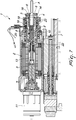
Figure 1 is a cross-sectional side view, taken along a longitudinal plane, of a device according to the invention in a first operating configuration, which is driven by a motor/pulley assembly; -
Figure 2 is a cross-sectional side view, taken along a longitudinal plane, of the device inFigure 1 in a second operating configuration; -
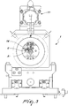
Figure 3 is a front elevation view of the device inFigure 1 ; -
Figure 4 is a schematic front elevation view of a first arrangement of the tool with respect to the bar in the device inFigure 1 ; -
Figure 5 is a schematic front elevation view of a second arrangement of the tool with respect to the bar in the device inFigure 1 ; -
Figure 6 is a schematic front elevation view of a third arrangement of the tool with respect to the bar in the device inFigure 1 ; -
Figure 7 is a cross-sectional side view, taken along a longitudinal plane, of a device according to the invention in a first operating configuration, which is driven by a linear actuator. - With particular reference to the figures, the
reference numeral 1 generally designates a turning device with static bar A. - The
device 1 comprises amotor 2 of which the drivingshaft 3 supports a sleeve 4, which defines aseat 5 for temporarily accommodating at least one portion of the bar A being machined. - A
machining tool 6 is coupled on the sleeve 4 (directly or indirectly, i.e. with the interposition of other components). - A secondary shaft 7 is interposed between the
driving shaft 3 of themotor 2 and the sleeve 4 and is coupled to thescrew 8 of afirst assembly 9 which is constituted by a first recirculating-ball screw 8 and a respectivefirst lead screw 10. - The
lead screw 10 is integral with the sleeve 4. - It should be noted that the
motor 2, thedriving shaft 3, the secondary shaft 7, the first screw/lead screw assembly 9 and the sleeve 4 are hollow in thedevice 1 according to the invention; as will be seen below, this particular shape structure brings undoubted advantages in terms of cooling and lubrication (by allowing the passage of specific fluids). - Since these are axially-symmetrical components, it should be noted that they will have a substantially tubular shape structure; since all the cited components are mutually coaxial, the respective internal cavities will also be mutually coaxial.
- The sleeve 4 and the
first assembly 9 are conveniently coaxial. - The axis of the
driving shaft 3 on the other hand is parallel to and separate from the common axle of the sleeve 4 and of thefirst group 9, thus defining an eccentricity thereof with respect to such components. - It should furthermore be noted that the
device 1 according to the invention comprises anadjustment element 11, which is coupled to anadjustment shaft 12 which can be situated, in a specific application described by way of non-limiting example, in a position arranged opposite from the sleeve 4. - The
adjustment shaft 12 is in turn coupled (directly or indirectly, i.e. with the interposition of further components) to apusher shaft 13. - The
pusher shaft 13, through the secondary shaft 7, can generate the translation of thescrew 8 and the rotation of the lead screw 10 (as a direct consequence) of theassembly 9. - Such rotation of the
lead screw 10 implies a corresponding rotation of the sleeve 4 (which is integral with it) and a movement in a radial direction of thetool 6, i.e. in approach to/distancing from the axis of themotor 2. - In a specific embodiment which is described by way of non-limiting example, the terminal end of the
pusher shaft 13 is in turn coupled (in this case too it will generally be an indirect coupling, i.e. with the interposition of other components) to anend flange 14 that can rotate eccentrically on the sleeve 4. - The
tool 6, in this case, will be integral withsuch flange 14. - Again with reference to the embodiment cited by way of non-limiting example above, it should be noted that the rotations of the flange 14 (which as a result of the eccentricity will cause movements in a radial direction of the
tool 6, with consequent variation of the depth of the incision made by it on the bar A to be machined) will occur by virtue of the action of thepusher shaft 13, which by pushing on the first recirculating-ball screw 8 of the first screw/lead screw assembly 9 will determine a translation of thescrew 8, with consequent rotation of the lead screw 10 (which is integral with theflange 14, which will rotate eccentrically with respect to the sleeve 4). - According to a particular embodiment of undoubted practical and applicative interest, a
second assembly 15 can be interposed between theadjustment shaft 12 and thepusher shaft 13 and comprises a second recirculating-ball screw 16 with a correspondingsecond lead screw 17. - The
second screw 16 and thesecond lead screw 17 are, in such case, accommodated at least partially in the inner cavity of thedriving shaft 3 and thesecond lead screw 17 will be integral with thepusher shaft 13 which translates inside thedriving shaft 3. - The terminal end of the
pusher shaft 13, coupled to the first recirculating-ball screw 8, will ensure the corresponding translation, with consequent rotation of theflange 14 and displacement of thetool 6 toward or away from the common axle of the sleeve 4 and of the bar A to be machined. - With particular reference to an alternative embodiment to the one described previously, which is also extremely advantageous from an applicative point of view, the
adjustment element 11 can conveniently be a numerically-controlled linear actuator (of the type of a numerically-controlled electric cylinder, although the possibility of using different actuators powered by electricity, pneumatics, hydraulics and the like, is not excluded) which is provided with anadjustment shaft 12 which is coaxial to and integral with thepusher shaft 13. - It should be noted that in the
device 1 according to the invention thetool 6 is arranged radially with respect to the central hole of theflange 14, with the cutting edge protruding from the inner edge of such hole. - An eccentric rotation of the
flange 14, by virtue of the action of theadjustment element 11, generates a translation of the cutting edge in a direction which is radial with respect to the axis of the bar A to be machined and which coincides with the axis of the sleeve 4. - In order to permit a correct cooling and lubrication of the cutting edge of the
tool 6, as well as of the bar A that is subjected to turning, it should be noted that theadjustment shaft 12, the second assembly 15 (which comprises thesecond screw 16 and the second lead screw 17) and thepusher shaft 13 are axially hollow: thanks to the presence of such cavities (and of the axial cavities that are present in thefirst assembly 9, and the presence of a channel inside the flange 14) acontinuous duct 18 is therefore defined which leads to a dispensing nozzle which faces and is proximate to the cutting edge of thetool 6. -
Such passage 18 will be connected, upstream, to an apparatus for supplying refrigerant fluid (for example a pump that can ensure the necessary pressure is applied to the fluid conveyed in the passage 18), for the corresponding flow through thepassage 18 and the distribution onto the cutting edge of thetool 6 and onto the bar A during turning. - It should be noted that the dispensing nozzle can positively be of the type of an atomizer, a sprayer and the like; the possibility is not ruled out however of adopting a continuous flow of refrigeration and/or lubrication fluid dispensed by way of one or more nozzles or other dispensing devices.
- According to a particular embodiment of undoubted practical and applicative interest, the
adjustment element 11 comprises a servomotor which is coupled rigidly to theadjustment shaft 12. - The servomotor in such case can advantageously be arranged preferably in a configuration selected from coaxial with the
adjustment shaft 12, with direct coupling of the shaft of the servomotor to the adjustment shaft, and offset with respect to theadjustment shaft 12, with the interposition of transmission means preferably of the toothed type (for example the coupling can be implemented using gearwheels or by way of a toothed belt or a chain). In a preferred embodiment, the axis of the servomotor is parallel to the axis of the adjustment shaft 12 (embodiment shown by way of example in the accompanying figures). - It further needs to be specified that the
motor 2 is, preferably, an electrospindle with a hollow rotor. Hollow rotor electric motors used as electric spindles are traditional electric motors in which the rotor has an axial cavity inside which other components can be inserted (arranged), either integral with the rotor, such as thedriving shaft 3, or separate from it, such as thepusher shaft 13. - The driving
shaft 3 is supported bybearings motor 2. - Radial-
action bearings 21 are interposed between the drivingshaft 3 and the second recirculating-ball screw 16, accommodated at least partially inside the drivingshaft 3. - It should furthermore be noted that respective radial-
action bearings 22 are interposed between the secondary shaft 7 and thepusher shaft 13, arranged inside it, for supporting thepusher shaft 13 and its free axial translational movement according to a preset stroke (in order to allow the necessary thrust to be exerted on the first screw/lead screw assembly 9 intended to adjust the angular position of theflange 14 and therefore the interference of the tool 6 (more precisely of its cutting edge) with the bar to be machined A. - It should be noted on the other hand that the sleeve 4 is supported by
bearings 23 for radial and axial support, preferably of a type selected from conical roller bearings, inclined ball bearings and the like. - In practice the
device 1 according to the invention, during execution of the turning of a bar A, allows an adjustment of the interference of the cutting edge of thetool 6, which is carried out by way of the thrust exerted by thepusher shaft 13 on the first screw/lead screw assembly 9, which converts the translation imposed by thepusher shaft 13 on the first recirculating-ball screw 8 to a rotation of thelead screw 10, which is integral with thebracket 14 to which thetool 6 is coupled. Since thebracket 14 can rotate eccentrically with respect to the axis of the bar A, a rotation of it implies an approach (or distancing) of the cutting edge of thetool 6 toward (or away from) the axis of the bar A (displacement in a radial direction of the tool 6) and therefore a variation of the depth of incision of the cutting edge on the bar A. - Advantageously the present invention solves the above mentioned problems, by providing a
turning device 1 with static bar A that ensures a high level of precision: in fact thetool 6 is rigidly coupled to thebracket 14 and is not in a cantilevered arrangement, thus minimizing the risk of inaccuracies owing to play or bending. - Conveniently the
device 1 according to the invention has a substantially low mass, which in any case does not exceed that of conventional devices. - Conveniently the
device 1 according to the invention is easily balanced, since most of the components are axially symmetrical and therefore, when rotated, do not cause vibrations owing to the presence of masses that are eccentric to that rotation. - Conveniently the
device 1 according to the invention is substantially free from play in particular, thanks to the presence of preloaded components, and is free from play at points of reversal of motion. - Advantageously in the
device 1 according to the invention the movement of thetool 6 is precise and efficient and can be executed even during the turning operations. - Profitably the
device 1 according to the invention requires minimal maintenance: in fact thebearings entire device 1 does not require frequent and periodic maintenance interventions, with considerable advantages in terms of cost and productivity with respect to conventional devices. - Effectively the
device 1 according to the invention does not require lubrication of the moving parts. - Positively the present invention makes it possible to provide a
turning device 1 with static bar A that is easily and practically implemented and substantially of low cost: such characteristics make thedevice 1 according to the invention an innovation that is safe in use.
Claims (8)
- A turning device for a static bar (A) of the type comprising a motor (2), a driving shaft (3) and a sleeve (4), which defines a seat (5) for temporarily accommodating at least one portion of the bar (A) being machined, a machining tool (6) being coupled directly or indirectly on said sleeve (4), wherein
a secondary shaft (7) is interposed between said driving shaft (3) of said motor (2) and said sleeve (4) and is coupled to a screw (8) of a first assembly (9) which is constituted by a first recirculating-ball screw (8) and a respective first lead screw (10), said lead screw (10) being integral with said sleeve (4),
said sleeve (4) and said first assembly (9) being coaxial and the axis of the driving shaft (3) being parallel to and separate from a common axis of the sleeve (4) and of the first assembly (9);
the device further comprises an adjustment element (11) which is coupled to a pusher shaft (13) which is associated with said secondary shaft (7),
said pusher shaft (13), through said secondary shaft (7), causing a translation of the screw (8) and a rotation of said lead screw (10) of the assembly (9), with consequent rotation of said sleeve (4) and a movement in a radial direction of said tool (6). - The device according to claim 1, characterized in that a second assembly (15) is interposed between an adjustment shaft (12) and said pusher shaft (13) of said adjustment element and comprises a second recirculating-ball screw (16) with a corresponding second lead screw (17), said second screw (16) and said second lead screw (17) being accommodated at least partially in the inner cavity of said driving shaft (3) and said second lead screw (17) being integral with said pusher shaft (13) which translates inside said driving shaft (3), the terminal end of said pusher shaft (13) being coupled to said first recirculating-ball screw (8) for the corresponding translation, said tool (6) being integral with a flange (14) which can rotate eccentrically with respect to the terminal edge of said sleeve (4) by virtue of the action of said first lead screw (10).
- The device according to claim 1, characterized in that said adjustment element (11) is a numerically-controlled linear actuator which is provided with an adjustment shaft which is coaxial and integral with said pusher shaft (13).
- The device according to claim 1, characterized in that said motor (2), said driving shaft (3), said secondary shaft (7), said first screw/lead screw assembly (9) and said sleeve (4) are hollow, said cavity being adapted for the conveyance of a flow of fluid of the type selected preferably from a refrigerant fluid, a lubricant fluid and the like.
- The device according to claim 2, characterized in that said adjustment shaft (12), said second assembly (15) which comprises said second screw (16) and said second lead screw (17), and said pusher shaft (13) are axially hollow, a continuous duct (18) being defined in the cavity of said adjustment shaft (12), said second screw/lead screw assembly (15), said pusher shaft (13), said first screw/lead screw assembly (9) and a channel inside said flange (14), said duct (18) leading to a dispensing nozzle which faces and is proximate to the cutting edge of said tool (6), said duct (18) being connected upstream to an apparatus for supplying refrigerant fluid, for the flow thereof through the duct (18) and distribution onto the cutting edge of the tool (6) and onto the bar (A) during turning.
- The device according to claim 2, characterized in that said adjustment element (11) comprises a servomotor which is coupled rigidly to said adjustment shaft (12), said servomotor being arranged preferably in a configuration selected from coaxial to said adjustment shaft (12), with direct coupling of the shaft of the servomotor to the adjustment shaft (12), and offset with respect to said adjustment shaft (12), with the interposition of transmission means preferably of the toothed type.
- The device according to claim 1, characterized in that said motor (2) is an electrospindle with a hollow rotor.
- The device according to claim 2, characterized in that said machining tool (6) is arranged radially with respect to the central hole of said flange (14), with the cutting edge protruding with respect to the inner edge of said hole, an eccentric rotation of said flange (14), by virtue of the action of said adjustment element (11), generating a translation of said cutting edge in a direction which is radial with respect to the axis of the bar to be machined (A) and which coincides with the axis of said sleeve (4).
Applications Claiming Priority (1)
| Application Number | Priority Date | Filing Date | Title |
|---|---|---|---|
| IT102018000006221A IT201800006221A1 (en) | 2018-06-12 | 2018-06-12 | STATIC BAR TURNING DEVICE |
Publications (2)
| Publication Number | Publication Date |
|---|---|
| EP3581301A1 EP3581301A1 (en) | 2019-12-18 |
| EP3581301B1 true EP3581301B1 (en) | 2021-02-17 |
Family
ID=63762621
Family Applications (1)
| Application Number | Title | Priority Date | Filing Date |
|---|---|---|---|
| EP19178651.6A Active EP3581301B1 (en) | 2018-06-12 | 2019-06-06 | Turning device with static bar |
Country Status (3)
| Country | Link |
|---|---|
| US (1) | US20190375023A1 (en) |
| EP (1) | EP3581301B1 (en) |
| IT (1) | IT201800006221A1 (en) |
Families Citing this family (1)
| Publication number | Priority date | Publication date | Assignee | Title |
|---|---|---|---|---|
| KR101999330B1 (en) * | 2018-02-01 | 2019-07-11 | 칸워크홀딩 주식회사 | Electrical Driving System of Built-in Type for Machine Tools, And Method for Operating the Same |
Family Cites Families (4)
| Publication number | Priority date | Publication date | Assignee | Title |
|---|---|---|---|---|
| DE3034210C2 (en) * | 1980-09-11 | 1982-09-09 | Coromant Engineering GmbH Gesellschaft zur Projektierung von Industrieanlagen, 6941 Laudenbach | Adjustment drive for a tool cutting edge |
| SE515255C2 (en) * | 1998-07-10 | 2001-07-02 | Lidkoeping Machine Tools Ab | Lathe and a procedure for machining a workpiece in the lathe |
| DE502008001376D1 (en) * | 2007-10-23 | 2010-11-04 | Imoberdorf Holding Ag | Transfer machine with a facing unit |
| ES2432478B1 (en) * | 2011-12-22 | 2015-03-24 | Emag Holding Gmbh | THE TRANSMISSION OF ADDITIONAL MOVEMENTS TO ROTARY ELEMENTS OF MACHINES-TOOL. |
-
2018
- 2018-06-12 IT IT102018000006221A patent/IT201800006221A1/en unknown
-
2019
- 2019-06-06 EP EP19178651.6A patent/EP3581301B1/en active Active
- 2019-06-12 US US16/438,547 patent/US20190375023A1/en not_active Abandoned
Non-Patent Citations (1)
| Title |
|---|
| None * |
Also Published As
| Publication number | Publication date |
|---|---|
| IT201800006221A1 (en) | 2019-12-12 |
| US20190375023A1 (en) | 2019-12-12 |
| EP3581301A1 (en) | 2019-12-18 |
Similar Documents
| Publication | Publication Date | Title |
|---|---|---|
| US20100183395A1 (en) | Orbital drilling tool unit | |
| KR20090048402A (en) | Bar or Tube Workpiece Cutting Machine | |
| EP1635975B1 (en) | Orbital machining apparatus with drive element with drive pins | |
| EP3581301A1 (en) | Turning device with static bar | |
| KR101932193B1 (en) | Finishing machine for hole | |
| EP3571000B1 (en) | Composable machine tool comprising a kit for cylindrical and conical turning machining operations | |
| KR101450361B1 (en) | Working machine | |
| US3011368A (en) | Rough and finish boring machines | |
| US6772659B2 (en) | Tool head for use in machine tools | |
| JP2026508971A (en) | Apparatus and method for threading female threads | |
| KR100434182B1 (en) | groove processing method and apparatus of inner or outer side of a cylinder using end-mill | |
| KR20180039353A (en) | Equipped with a cup-shaped wire brush structure ofthe automatic deburring | |
| JP6781753B2 (en) | Lathe including guide bush | |
| RU2686426C1 (en) | Composite for cutting of long-length workpiece | |
| US5539966A (en) | Machining head for machining boards | |
| US4347770A (en) | Apparatus and method for radially cutting cylindrical material | |
| KR920010567B1 (en) | Turning machine assembly | |
| NL8006181A (en) | TOOL COMPENSATION MECHANISM. | |
| JP2019508278A (en) | Tool spindle | |
| KR20140143871A (en) | Computer numerical control machine tool | |
| RU2680487C2 (en) | Machine tool with onboard motor | |
| EP2332677B1 (en) | Lathe | |
| JP2633773B2 (en) | Rotation transmission mechanism of grinding device | |
| CN121424164A (en) | A CNC internal and external cylindrical composite grinding machine | |
| EP2604382A1 (en) | Spindle mounting head of a machine tool |
Legal Events
| Date | Code | Title | Description |
|---|---|---|---|
| PUAI | Public reference made under article 153(3) epc to a published international application that has entered the european phase |
Free format text: ORIGINAL CODE: 0009012 |
|
| STAA | Information on the status of an ep patent application or granted ep patent |
Free format text: STATUS: THE APPLICATION HAS BEEN PUBLISHED |
|
| AK | Designated contracting states |
Kind code of ref document: A1 Designated state(s): AL AT BE BG CH CY CZ DE DK EE ES FI FR GB GR HR HU IE IS IT LI LT LU LV MC MK MT NL NO PL PT RO RS SE SI SK SM TR |
|
| AX | Request for extension of the european patent |
Extension state: BA ME |
|
| STAA | Information on the status of an ep patent application or granted ep patent |
Free format text: STATUS: REQUEST FOR EXAMINATION WAS MADE |
|
| RBV | Designated contracting states (corrected) |
Designated state(s): AL AT BE BG CH CY CZ DE DK EE ES FI FR GB GR HR HU IE IS IT LI LT LU LV MC MK MT NL NO PL PT RO RS SE SI SK SM TR |
|
| 17P | Request for examination filed |
Effective date: 20200316 |
|
| RIC1 | Information provided on ipc code assigned before grant |
Ipc: B23B 3/26 20060101AFI20200728BHEP Ipc: B23B 29/034 20060101ALI20200728BHEP |
|
| GRAP | Despatch of communication of intention to grant a patent |
Free format text: ORIGINAL CODE: EPIDOSNIGR1 |
|
| STAA | Information on the status of an ep patent application or granted ep patent |
Free format text: STATUS: GRANT OF PATENT IS INTENDED |
|
| INTG | Intention to grant announced |
Effective date: 20200907 |
|
| GRAS | Grant fee paid |
Free format text: ORIGINAL CODE: EPIDOSNIGR3 |
|
| GRAA | (expected) grant |
Free format text: ORIGINAL CODE: 0009210 |
|
| STAA | Information on the status of an ep patent application or granted ep patent |
Free format text: STATUS: THE PATENT HAS BEEN GRANTED |
|
| AK | Designated contracting states |
Kind code of ref document: B1 Designated state(s): AL AT BE BG CH CY CZ DE DK EE ES FI FR GB GR HR HU IE IS IT LI LT LU LV MC MK MT NL NO PL PT RO RS SE SI SK SM TR |
|
| REG | Reference to a national code |
Ref country code: GB Ref legal event code: FG4D |
|
| REG | Reference to a national code |
Ref country code: CH Ref legal event code: EP |
|
| REG | Reference to a national code |
Ref country code: DE Ref legal event code: R096 Ref document number: 602019002544 Country of ref document: DE |
|
| REG | Reference to a national code |
Ref country code: AT Ref legal event code: REF Ref document number: 1360835 Country of ref document: AT Kind code of ref document: T Effective date: 20210315 |
|
| REG | Reference to a national code |
Ref country code: IE Ref legal event code: FG4D |
|
| REG | Reference to a national code |
Ref country code: LT Ref legal event code: MG9D |
|
| REG | Reference to a national code |
Ref country code: NL Ref legal event code: MP Effective date: 20210217 |
|
| PG25 | Lapsed in a contracting state [announced via postgrant information from national office to epo] |
Ref country code: NO Free format text: LAPSE BECAUSE OF FAILURE TO SUBMIT A TRANSLATION OF THE DESCRIPTION OR TO PAY THE FEE WITHIN THE PRESCRIBED TIME-LIMIT Effective date: 20210517 Ref country code: PT Free format text: LAPSE BECAUSE OF FAILURE TO SUBMIT A TRANSLATION OF THE DESCRIPTION OR TO PAY THE FEE WITHIN THE PRESCRIBED TIME-LIMIT Effective date: 20210617 Ref country code: LT Free format text: LAPSE BECAUSE OF FAILURE TO SUBMIT A TRANSLATION OF THE DESCRIPTION OR TO PAY THE FEE WITHIN THE PRESCRIBED TIME-LIMIT Effective date: 20210217 Ref country code: GR Free format text: LAPSE BECAUSE OF FAILURE TO SUBMIT A TRANSLATION OF THE DESCRIPTION OR TO PAY THE FEE WITHIN THE PRESCRIBED TIME-LIMIT Effective date: 20210518 Ref country code: FI Free format text: LAPSE BECAUSE OF FAILURE TO SUBMIT A TRANSLATION OF THE DESCRIPTION OR TO PAY THE FEE WITHIN THE PRESCRIBED TIME-LIMIT Effective date: 20210217 Ref country code: BG Free format text: LAPSE BECAUSE OF FAILURE TO SUBMIT A TRANSLATION OF THE DESCRIPTION OR TO PAY THE FEE WITHIN THE PRESCRIBED TIME-LIMIT Effective date: 20210517 Ref country code: HR Free format text: LAPSE BECAUSE OF FAILURE TO SUBMIT A TRANSLATION OF THE DESCRIPTION OR TO PAY THE FEE WITHIN THE PRESCRIBED TIME-LIMIT Effective date: 20210217 |
|
| REG | Reference to a national code |
Ref country code: AT Ref legal event code: MK05 Ref document number: 1360835 Country of ref document: AT Kind code of ref document: T Effective date: 20210217 |
|
| PG25 | Lapsed in a contracting state [announced via postgrant information from national office to epo] |
Ref country code: RS Free format text: LAPSE BECAUSE OF FAILURE TO SUBMIT A TRANSLATION OF THE DESCRIPTION OR TO PAY THE FEE WITHIN THE PRESCRIBED TIME-LIMIT Effective date: 20210217 Ref country code: SE Free format text: LAPSE BECAUSE OF FAILURE TO SUBMIT A TRANSLATION OF THE DESCRIPTION OR TO PAY THE FEE WITHIN THE PRESCRIBED TIME-LIMIT Effective date: 20210217 Ref country code: PL Free format text: LAPSE BECAUSE OF FAILURE TO SUBMIT A TRANSLATION OF THE DESCRIPTION OR TO PAY THE FEE WITHIN THE PRESCRIBED TIME-LIMIT Effective date: 20210217 Ref country code: NL Free format text: LAPSE BECAUSE OF FAILURE TO SUBMIT A TRANSLATION OF THE DESCRIPTION OR TO PAY THE FEE WITHIN THE PRESCRIBED TIME-LIMIT Effective date: 20210217 Ref country code: LV Free format text: LAPSE BECAUSE OF FAILURE TO SUBMIT A TRANSLATION OF THE DESCRIPTION OR TO PAY THE FEE WITHIN THE PRESCRIBED TIME-LIMIT Effective date: 20210217 |
|
| PG25 | Lapsed in a contracting state [announced via postgrant information from national office to epo] |
Ref country code: IS Free format text: LAPSE BECAUSE OF FAILURE TO SUBMIT A TRANSLATION OF THE DESCRIPTION OR TO PAY THE FEE WITHIN THE PRESCRIBED TIME-LIMIT Effective date: 20210617 |
|
| PG25 | Lapsed in a contracting state [announced via postgrant information from national office to epo] |
Ref country code: CZ Free format text: LAPSE BECAUSE OF FAILURE TO SUBMIT A TRANSLATION OF THE DESCRIPTION OR TO PAY THE FEE WITHIN THE PRESCRIBED TIME-LIMIT Effective date: 20210217 Ref country code: EE Free format text: LAPSE BECAUSE OF FAILURE TO SUBMIT A TRANSLATION OF THE DESCRIPTION OR TO PAY THE FEE WITHIN THE PRESCRIBED TIME-LIMIT Effective date: 20210217 Ref country code: SM Free format text: LAPSE BECAUSE OF FAILURE TO SUBMIT A TRANSLATION OF THE DESCRIPTION OR TO PAY THE FEE WITHIN THE PRESCRIBED TIME-LIMIT Effective date: 20210217 Ref country code: AT Free format text: LAPSE BECAUSE OF FAILURE TO SUBMIT A TRANSLATION OF THE DESCRIPTION OR TO PAY THE FEE WITHIN THE PRESCRIBED TIME-LIMIT Effective date: 20210217 |
|
| REG | Reference to a national code |
Ref country code: DE Ref legal event code: R097 Ref document number: 602019002544 Country of ref document: DE |
|
| PG25 | Lapsed in a contracting state [announced via postgrant information from national office to epo] |
Ref country code: RO Free format text: LAPSE BECAUSE OF FAILURE TO SUBMIT A TRANSLATION OF THE DESCRIPTION OR TO PAY THE FEE WITHIN THE PRESCRIBED TIME-LIMIT Effective date: 20210217 Ref country code: SK Free format text: LAPSE BECAUSE OF FAILURE TO SUBMIT A TRANSLATION OF THE DESCRIPTION OR TO PAY THE FEE WITHIN THE PRESCRIBED TIME-LIMIT Effective date: 20210217 Ref country code: DK Free format text: LAPSE BECAUSE OF FAILURE TO SUBMIT A TRANSLATION OF THE DESCRIPTION OR TO PAY THE FEE WITHIN THE PRESCRIBED TIME-LIMIT Effective date: 20210217 |
|
| PLBE | No opposition filed within time limit |
Free format text: ORIGINAL CODE: 0009261 |
|
| STAA | Information on the status of an ep patent application or granted ep patent |
Free format text: STATUS: NO OPPOSITION FILED WITHIN TIME LIMIT |
|
| 26N | No opposition filed |
Effective date: 20211118 |
|
| PG25 | Lapsed in a contracting state [announced via postgrant information from national office to epo] |
Ref country code: MC Free format text: LAPSE BECAUSE OF FAILURE TO SUBMIT A TRANSLATION OF THE DESCRIPTION OR TO PAY THE FEE WITHIN THE PRESCRIBED TIME-LIMIT Effective date: 20210217 Ref country code: AL Free format text: LAPSE BECAUSE OF FAILURE TO SUBMIT A TRANSLATION OF THE DESCRIPTION OR TO PAY THE FEE WITHIN THE PRESCRIBED TIME-LIMIT Effective date: 20210217 Ref country code: ES Free format text: LAPSE BECAUSE OF FAILURE TO SUBMIT A TRANSLATION OF THE DESCRIPTION OR TO PAY THE FEE WITHIN THE PRESCRIBED TIME-LIMIT Effective date: 20210217 |
|
| PG25 | Lapsed in a contracting state [announced via postgrant information from national office to epo] |
Ref country code: SI Free format text: LAPSE BECAUSE OF FAILURE TO SUBMIT A TRANSLATION OF THE DESCRIPTION OR TO PAY THE FEE WITHIN THE PRESCRIBED TIME-LIMIT Effective date: 20210217 |
|
| REG | Reference to a national code |
Ref country code: BE Ref legal event code: MM Effective date: 20210630 |
|
| PG25 | Lapsed in a contracting state [announced via postgrant information from national office to epo] |
Ref country code: LU Free format text: LAPSE BECAUSE OF NON-PAYMENT OF DUE FEES Effective date: 20210606 |
|
| PG25 | Lapsed in a contracting state [announced via postgrant information from national office to epo] |
Ref country code: IE Free format text: LAPSE BECAUSE OF NON-PAYMENT OF DUE FEES Effective date: 20210606 |
|
| PG25 | Lapsed in a contracting state [announced via postgrant information from national office to epo] |
Ref country code: IS Free format text: LAPSE BECAUSE OF FAILURE TO SUBMIT A TRANSLATION OF THE DESCRIPTION OR TO PAY THE FEE WITHIN THE PRESCRIBED TIME-LIMIT Effective date: 20210617 Ref country code: FR Free format text: LAPSE BECAUSE OF NON-PAYMENT OF DUE FEES Effective date: 20210630 |
|
| PG25 | Lapsed in a contracting state [announced via postgrant information from national office to epo] |
Ref country code: BE Free format text: LAPSE BECAUSE OF NON-PAYMENT OF DUE FEES Effective date: 20210630 |
|
| REG | Reference to a national code |
Ref country code: CH Ref legal event code: PL |
|
| PG25 | Lapsed in a contracting state [announced via postgrant information from national office to epo] |
Ref country code: LI Free format text: LAPSE BECAUSE OF NON-PAYMENT OF DUE FEES Effective date: 20220630 Ref country code: CH Free format text: LAPSE BECAUSE OF NON-PAYMENT OF DUE FEES Effective date: 20220630 |
|
| PG25 | Lapsed in a contracting state [announced via postgrant information from national office to epo] |
Ref country code: CY Free format text: LAPSE BECAUSE OF FAILURE TO SUBMIT A TRANSLATION OF THE DESCRIPTION OR TO PAY THE FEE WITHIN THE PRESCRIBED TIME-LIMIT Effective date: 20210217 |
|
| P01 | Opt-out of the competence of the unified patent court (upc) registered |
Effective date: 20230528 |
|
| PG25 | Lapsed in a contracting state [announced via postgrant information from national office to epo] |
Ref country code: HU Free format text: LAPSE BECAUSE OF FAILURE TO SUBMIT A TRANSLATION OF THE DESCRIPTION OR TO PAY THE FEE WITHIN THE PRESCRIBED TIME-LIMIT; INVALID AB INITIO Effective date: 20190606 |
|
| GBPC | Gb: european patent ceased through non-payment of renewal fee |
Effective date: 20230606 |
|
| PG25 | Lapsed in a contracting state [announced via postgrant information from national office to epo] |
Ref country code: MK Free format text: LAPSE BECAUSE OF FAILURE TO SUBMIT A TRANSLATION OF THE DESCRIPTION OR TO PAY THE FEE WITHIN THE PRESCRIBED TIME-LIMIT Effective date: 20210217 Ref country code: GB Free format text: LAPSE BECAUSE OF NON-PAYMENT OF DUE FEES Effective date: 20230606 |
|
| PG25 | Lapsed in a contracting state [announced via postgrant information from national office to epo] |
Ref country code: MT Free format text: LAPSE BECAUSE OF FAILURE TO SUBMIT A TRANSLATION OF THE DESCRIPTION OR TO PAY THE FEE WITHIN THE PRESCRIBED TIME-LIMIT Effective date: 20210217 |
|
| PGFP | Annual fee paid to national office [announced via postgrant information from national office to epo] |
Ref country code: DE Payment date: 20250613 Year of fee payment: 7 |
|
| PGFP | Annual fee paid to national office [announced via postgrant information from national office to epo] |
Ref country code: IT Payment date: 20250520 Year of fee payment: 7 |
|
| PG25 | Lapsed in a contracting state [announced via postgrant information from national office to epo] |
Ref country code: TR Free format text: LAPSE BECAUSE OF FAILURE TO SUBMIT A TRANSLATION OF THE DESCRIPTION OR TO PAY THE FEE WITHIN THE PRESCRIBED TIME-LIMIT Effective date: 20210217 |