EP3581262A1 - Agitator arrangement - Google Patents
Agitator arrangement Download PDFInfo
- Publication number
- EP3581262A1 EP3581262A1 EP18177890.3A EP18177890A EP3581262A1 EP 3581262 A1 EP3581262 A1 EP 3581262A1 EP 18177890 A EP18177890 A EP 18177890A EP 3581262 A1 EP3581262 A1 EP 3581262A1
- Authority
- EP
- European Patent Office
- Prior art keywords
- impeller
- openings
- agitator arrangement
- cleaning
- shaft
- Prior art date
- Legal status (The legal status is an assumption and is not a legal conclusion. Google has not performed a legal analysis and makes no representation as to the accuracy of the status listed.)
- Granted
Links
Images




Classifications
-
- B—PERFORMING OPERATIONS; TRANSPORTING
- B08—CLEANING
- B08B—CLEANING IN GENERAL; PREVENTION OF FOULING IN GENERAL
- B08B3/00—Cleaning by methods involving the use or presence of liquid or steam
- B08B3/02—Cleaning by the force of jets or sprays
-
- B—PERFORMING OPERATIONS; TRANSPORTING
- B01—PHYSICAL OR CHEMICAL PROCESSES OR APPARATUS IN GENERAL
- B01F—MIXING, e.g. DISSOLVING, EMULSIFYING OR DISPERSING
- B01F27/00—Mixers with rotary stirring devices in fixed receptacles; Kneaders
- B01F27/05—Stirrers
- B01F27/11—Stirrers characterised by the configuration of the stirrers
- B01F27/19—Stirrers with two or more mixing elements mounted in sequence on the same axis
- B01F27/191—Stirrers with two or more mixing elements mounted in sequence on the same axis with similar elements
-
- B—PERFORMING OPERATIONS; TRANSPORTING
- B01—PHYSICAL OR CHEMICAL PROCESSES OR APPARATUS IN GENERAL
- B01F—MIXING, e.g. DISSOLVING, EMULSIFYING OR DISPERSING
- B01F27/00—Mixers with rotary stirring devices in fixed receptacles; Kneaders
- B01F27/21—Mixers with rotary stirring devices in fixed receptacles; Kneaders characterised by their rotating shafts
- B01F27/2121—Mixers with rotary stirring devices in fixed receptacles; Kneaders characterised by their rotating shafts composed of interconnected parts
-
- B—PERFORMING OPERATIONS; TRANSPORTING
- B01—PHYSICAL OR CHEMICAL PROCESSES OR APPARATUS IN GENERAL
- B01F—MIXING, e.g. DISSOLVING, EMULSIFYING OR DISPERSING
- B01F27/00—Mixers with rotary stirring devices in fixed receptacles; Kneaders
- B01F27/21—Mixers with rotary stirring devices in fixed receptacles; Kneaders characterised by their rotating shafts
- B01F27/2122—Hollow shafts
-
- B—PERFORMING OPERATIONS; TRANSPORTING
- B01—PHYSICAL OR CHEMICAL PROCESSES OR APPARATUS IN GENERAL
- B01F—MIXING, e.g. DISSOLVING, EMULSIFYING OR DISPERSING
- B01F27/00—Mixers with rotary stirring devices in fixed receptacles; Kneaders
- B01F27/80—Mixers with rotary stirring devices in fixed receptacles; Kneaders with stirrers rotating about a substantially vertical axis
- B01F27/91—Mixers with rotary stirring devices in fixed receptacles; Kneaders with stirrers rotating about a substantially vertical axis with propellers
-
- B—PERFORMING OPERATIONS; TRANSPORTING
- B01—PHYSICAL OR CHEMICAL PROCESSES OR APPARATUS IN GENERAL
- B01F—MIXING, e.g. DISSOLVING, EMULSIFYING OR DISPERSING
- B01F35/00—Accessories for mixers; Auxiliary operations or auxiliary devices; Parts or details of general application
- B01F35/10—Maintenance of mixers
- B01F35/145—Washing or cleaning mixers not provided for in other groups in this subclass; Inhibiting build-up of material on machine parts using other means
- B01F35/1452—Washing or cleaning mixers not provided for in other groups in this subclass; Inhibiting build-up of material on machine parts using other means using fluids
- B01F35/1453—Washing or cleaning mixers not provided for in other groups in this subclass; Inhibiting build-up of material on machine parts using other means using fluids by means of jets of fluid, e.g. air
-
- B—PERFORMING OPERATIONS; TRANSPORTING
- B08—CLEANING
- B08B—CLEANING IN GENERAL; PREVENTION OF FOULING IN GENERAL
- B08B9/00—Cleaning hollow articles by methods or apparatus specially adapted thereto
- B08B9/08—Cleaning containers, e.g. tanks
- B08B9/093—Cleaning containers, e.g. tanks by the force of jets or sprays
- B08B9/0936—Cleaning containers, e.g. tanks by the force of jets or sprays using rotating jets
Definitions
- the second impeller comprises at least 4, specifically at least 6, more specifically at least 8 and even more specifically at least 16 openings configured for spraying a cleaning liquid on the first impeller.
- at least 4 openings configured for spraying the cleaning liquid on the first impeller are required.
- the openings are preferably more or less equally distributed around the circumference of the hub of the second impeller.
- the agitator arrangement 2 comprises a rotatable hollow shaft 4 extending in an axial direction 5, which is perpendicular to a transverse direction 6.
- the axial direction 5 may for example be parallel with a vertical direction
- the transverse direction 6 may for example be parallel with a horizontal direction.
- the second impeller 8 comprises opening configured for spraying a cleaning liquid on the first impeller 7 during cleaning of the agitator arrangement.
- the first and second shaft sections 22, 23, 24 may be threadingly attached to first and/or second impeller 7, 8.
- the second shaft section 24 may be threadingly attached to the first axial end 27 of the second impeller 8.
- Design aspects of the plurality of openings that have an effect of the spraying of a cleaning liquid on the first impeller for cleaning the first impeller are selected according to the specific circumstances of each implementation, taking into account factors like type of liquid food product to be cleaned away, the pressure, temperature and detergent of the cleaning liquid, the axial distance between the first and second impellers 7, 8, the radial length of the impeller blades 31, or the like.
- a centre of an outlet of the plurality of openings 9, respectively, is located a distance 33 of about 10 - 50 mm from an exterior surface 32 of the rotatable hollow shaft, as seen in a transverse direction 6, which is perpendicular to the axial direction 5 of the rotatable hollow shaft 4.
- the second impeller may for example comprise at least 4, specifically at least 6, more specifically at least 8 and even more specifically at least 16 openings 9 configured for spraying a cleaning liquid on the first impeller 7.
- the second impeller comprises 16 openings 9.
- the second impeller 8 of the example embodiment of figure 4 further comprises a total of three impeller blades 31, equally distributed around the circumference of the second impeller 8. However, the number of impeller blades can be varied.
- the second impeller 8 further includes an impeller hub 34 having the impeller blades 31 secured thereto.
- the impeller hub 34 enables a more modular design of the agitator arrangement by assembling the rotatable shaft 4 out of a suitable combination of first and second shaft sections 22-24 and impeller hubs 34.
- the first and second shaft sections 22-24 may for example be threadingly attached to the impeller hubs 34, either directly or by means of an individual attachment collar 35 as shown in the example embodiment of figure 3 .
- the plurality of openings 9 configured for spraying cleaning liquid on the first impeller 7 may for example be located in the impeller hub. Thereby the impeller blades 31 and the shaft sections 22-24 of the tubular shaft 4 may have a less complicated design and thus being more cost-efficient.
- Figure 5 shows a cross-sectional view along an axial plane of the impeller hub 34.
- the impeller hub may comprise a first part 40 and a second part 41, wherein the first and second parts 40, 41 are attached to each other.
- the first part 40 is configured for being attached to the tubular shaft 4
- the second part 41 is configured to be free from connections to the mixing tank 1 for enabling simplified cleaning of the mixing tank 1 and agitator arrangement 2.
- the second part 41 of the impeller hub 34, or any other part of the agitator arrangement 2 may have connection arrangement for rotatable connecting the rotatable hollow haft 4 of the agitator arrangement 2 to a bearing support for rotatably attaching the second part 41 to the mixing tank 1.
- Such additional fastening of the agitator arrangement 2 may be necessary for avoiding too large bending motion of the rotatable hollow shaft 4 during rotation of the first and second impellers 7, 8.
- the agitator arrangement may comprise at least one opening 50 in a second part 41 of the hub 34 for spraying cleaning liquid on a bottom bearing support of the agitator arrangement 2 and/or bottom of the mixing tank 1.
- the second impeller 34 further has a more modular design wherein a single type of first part 40 may be connected with various different types of second parts 41, for example for enabling attachment to various types and sizes of impeller blades to the impeller hub 34.
- the modular design of the hub 34 enables drilling from the inside of the hub 34 before the first and second parts 40, 41 of the hub have been secured to each other.
- the second part 41 of the impeller hub 43 may have a substantially cylindrical shape, and one axial side of the second part 41 may be fastened to the radially outer edge of the flange section 58 of the first part 40 of the hub 34.
Landscapes
- Chemical & Material Sciences (AREA)
- Chemical Kinetics & Catalysis (AREA)
- Engineering & Computer Science (AREA)
- Mechanical Engineering (AREA)
- Mixers Of The Rotary Stirring Type (AREA)
- Accessories For Mixers (AREA)
Abstract
Description
- The disclosure relates to an agitator arrangement for mixing a liquid in a mixing tank and for cleaning the mixing tank. The disclosure also relates to a mixing tank comprising such an agitator arrangement.
- The disclosure can be arranged for example in the liquid food industry of dairy, beverage, brewing, processed foods, pharmaceutical and cosmetics, or the like.
- In the food and beverage industry mixing tanks and agitators should preferably be designed for providing highly efficient mixing, improved cost-efficiency, zero in-tank maintenance and eliminating contamination risks.
- Consequently, there is a continuous demand for improved agitation of the liquid within the tank and to use larger tanks with maintained agitation capacity, while also enabling efficient deaeration of the liquid within the tank and adequate cleaning of the agitator arrangement and tank interior.
- However, despite the activities in the field, currently known solutions are not entirely satisfactory. There is therefore still a demand for an improved agitator arrangement, which is capable of meeting the above-mentioned requirements.
- This section provides a general summary of the disclosure, and is not a comprehensive disclosure of its full scope or all of its features.
- An object of the present disclosure is to provide an agitator arrangement and mixing tank including such an agitator arrangement, where the previously mentioned problems are avoided. This object is at least partly achieved by the features of the independent claims. The dependent claims contain further developments of the agitator arrangement.
- According to a first aspect of the present disclosure, there is provided an agitator arrangement for mixing a liquid in a mixing tank and for cleaning the mixing tank. The agitator arrangement comprises a rotatable hollow shaft extending in an axial direction, a first impeller secured to the shaft at a first axial position and a second impeller secured to the shaft at a second axial position. The second impeller comprises a plurality of openings configured for spraying a cleaning liquid on the first impeller for cleaning the first impeller.
- Having two impellers located different axial positions along the shaft enables significantly improved agitation of the liquid within the tank compared with a single impeller. Moreover, the two axially displaced impellers alternatively enables use of a larger mixing tank with maintained agitation capacity.
- Finally, for ensuring efficient and satisfactory cleaning of the agitator arrangement having at least two impellers, the second impeller comprises a plurality of openings configured for spraying a cleaning liquid on the first impeller for cleaning the first impeller.
- Further advantages are achieved by implementing one or several of the features of the dependent claims.
- In one example embodiment, the second impeller includes an impeller hub and impeller blades secured to the impeller hub, and wherein the plurality of openings are located in the impeller hub. Having the plurality of openings located in the impeller hub enables simplified manufacturing and more cost-effective design of the agitator arrangement because thereby no additional cleaning units have to be manufactured and installed along the rotatable hollow shaft. Instead, the impeller hub has dual functionality in terms of securing the impeller blades and acting as spray unit for the cleaning liquid.
- According to a further example embodiment, the second impeller comprises at least 4, specifically at least 6, more specifically at least 8 and even more specifically at least 16 openings configured for spraying a cleaning liquid on the first impeller. For ensuring adequate cleaning of the first impeller at least 4 openings configured for spraying the cleaning liquid on the first impeller are required. The openings are preferably more or less equally distributed around the circumference of the hub of the second impeller.
- According to still a further example embodiment, the agitator arrangement comprises a flow path from a first end region of the rotatable hollow shaft to the plurality of openings, such that pressurized cleaning liquid supplied at the first end region of the rotatable hollow shaft may be sprayed out at the plurality of openings. The rotatable shaft thus has dual functionality in terms of transmitting rotational motion to the impellers and conveying pressurized cleaning liquid from a source outside of the mixing tank to the openings of the second impeller, thereby providing a cost-effective design of the agitator arrangement.
- According to a further example embodiment, the plurality of openings have a substantially cylindrical shape with a diameter of 1 - 4 mm, and specifically of 1.5 - 3 mm. The substantially cylindrical shape enables the openings to be cost-efficiently drilled. Moreover, the specific diameter of the openings has during experimental testing shown to provide a strong cleaning spray with adequate flow and coverage for enabling efficient cleaning of the first impeller.
- According to a further example embodiment, an axial orientation of the plurality of openings, respectively, define an inclination angle of 1-45 degrees, specifically 1-10 degrees, and more specifically 2-5 degrees, with respect to the axial direction of the rotatable hollow shaft. A suitable inclination angle of the axial orientation of the plurality of openings depends on parameters such as the distance between the first and second impeller and the diameter of the first impeller. The defined ranges generally provide a satisfactory cleaning result of the first impeller.
- According to a further example embodiment, a centre of an outlet of the plurality of openings, respectively, is located 10 - 50 mm from an exterior surface of the rotatable hollow shaft, as seen in a direction perpendicular to the axial direction of the rotatable hollow shaft. This range of distance the centre of an outlet of the plurality of openings, respectively and an exterior surface of the rotatable hollow shaft enables location of the openings in the hub of the second impeller or another relatively small unit attached to the rotatable shaft for simplified and cost-effective design. The flow path from the hollow rotatable shaft to the openings, in a direction perpendicular to the axial direction, may also be held short, thereby also resulting in simplified and cost-effective design.
- According to a further example embodiment, an axial orientation of the plurality of openings, respectively, define an angle of about 90 degrees with respect to a plane of an interior surface of the impeller hub at a location of each corresponding opening. This enables simplified manufacturing of the impeller hub because the openings may be more easily formed, for example by drilling, when the openings extend perpendicular to the surface of the impeller hub at a location of each corresponding opening. Forming an opening, for example by drilling, at an angle α, wherein 0 < α < 90 degrees, is increasingly difficult upon departing from the perpendicular (90 degrees) orientation to a surface.
- According to a further example embodiment, the impeller hub comprises a first part and a second part, wherein the first and second parts are attached to each other, and wherein the plurality of opening are located in the first part and the impeller blades are attached to the second part. Having the impeller hub formed of at least two parts enables simplified and more cost-effective manufacturing of the hub, because the first part may be specifically designed for enabling appropriate location, orientation and manufacturing of the openings, while the second part may be specifically designed for enabling appropriate location, fixation and manufacturing of the impeller blades. The first and second part may thereafter be joined, for example by welding, threading connection, etc.
- According to a further example embodiment, a distance between the first axial position and the second axial position is 400 - 4000 mm, specifically 500 - 3000 mm, in the axial direction of the rotatable hollow shaft. These ranges enable improved agitation of the liquid within the tank, as well as use of larger tanks with maintained agitation capacity.
- According to a further example embodiment, the rotatable hollow shaft comprises one or more first shaft sections extending from the first end region of the rotatable shaft to a first axial end of the first impeller, and a second shaft section extending from a second axial end of the first impeller to a first axial end of the second impeller. Having the rotatable designed in a modular form with at least a first and a second shaft section enables simplified installation, manufacturing and servicing of the agitator arrangement.
- According to a further example embodiment, the first impeller is free from openings configured for spraying a cleaning liquid. It is known that deaeration of a liquid food product within the tank results in reduced oxygen content in liquid food products leads to extended shelf life and improved taste stability. Stripping gas for deaeration of the liquid food product is preferably introduced, for example via openings in the agitator arrangement, at a low position within the tank for enabling a maximal reaction time with the liquid food product before the stripping gas bubbles reach the surface of the liquid food product and are vented. Consequently, for providing efficient deaeration of the liquid within the tank, it is preferred avoiding introduction of a stripping gas in the region of the uppermost-located impeller of the first and second impellers, because this would enable a large part of the stripping gas to enter the liquid food product in the region of the uppermost-located impeller. However, since the openings in the agitator arrangement for ejecting stripping gas into the liquid food product often also are used for injecting cleaning liquid into the mixing tank for cleaning the interior of the tank and the agitator arrangement in-between batches of liquid food product, it is preferred avoiding having openings in the first impeller configured for spraying a cleaning liquid.
- This design further underlines the need for providing the second impeller with a plurality of openings configured for spraying a cleaning liquid on the first impeller for cleaning the first impeller, because the lack of openings in the first impeller configured for spraying a cleaning liquid makes cleaning of the first impeller more difficult.
- According to a further example embodiment, the second impeller further comprises at least one additional opening for each blade of the second impeller and configured for spraying a cleaning liquid on the blades of the second impeller. Thereby, cleaning liquid may be sprayed onto the blades of the second impeller for providing adequate cleaning of the second impeller.
- According to a further example embodiment, the agitator arrangement may further comprise a third impeller secured to the shaft at a third axial position. The third impeller may for example include a plurality of openings configured for spraying a cleaning liquid on the first and/or second impeller for cleaning the first and/or second impeller. A third impeller may further enable improved agitation of the liquid within the tank, as well as use of larger tanks with maintained agitation capacity.
- Alternatively, the third impeller may be free from openings configured for spraying a cleaning liquid. For example, if the third impeller is located above the first and second impeller, the third impeller may be free from openings configured for spraying a cleaning liquid for enabling improved deaeration of the liquid food product, as discussed above.
- According to a further example embodiment, a first end region of the rotatable shaft is configured to be attached to an upper side of the mixing tank, and the first impeller is located between the first end region and the second impeller.
- According to a further example embodiment, the disclosure relates to a mixing tank including an agitator arrangement as described above. The first impeller may be located above the second impeller in the mixing tank.
- According to a further example embodiment, a first end region of the rotatable shaft is attached to an upper side of the mixing tank, and a second end region of the rotatable shaft is free from attachment to the mixing tank. This simplifies the installation of the agitator arrangement within the mixing tank and eliminates the need to clean a bottom bearing attachment of the agitator arrangement to the mixing tank.
- According to a further example embodiment, a first end region of the rotatable shaft is attached to an upper side of the mixing tank and a second end region of the rotatable shaft is attached to a lower side of the mixing tank, wherein the agitator arrangement comprises openings in lower cleaning hub for spraying cleaning liquid on a bottom bearing support of the agitator arrangement and/or bottom of the mixing tank.
- Further features of, and advantages with, the present disclosure will become apparent when studying the appended claims and the following description. The skilled person realize that different features of the present disclosure may be combined to create embodiments other than those described in the following, without departing from the scope of the present disclosure.
- The various example embodiments of the disclosure, including its particular features and example advantages, will be readily understood from the following illustrative and non-limiting detailed description and the accompanying drawings, in which:
-
Fig. 1 is a sectional view through a mixing tank and further including an agitator arrangement; -
Fig. 2 is a cross-sectional view of theagitator arrangement 2 offigure 1 ; -
Fig. 3 is a cross-sectional view of the second impeller; -
Fig. 4 is a top-view of the second impeller; -
Fig. 5 shows a two-part hub of the second impeller; -
Fig. 6 shows a side view of the second impeller including three additional openings for spraying cleaning liquid on the blades of the second impeller; and -
Figure 7 shows a cross-sectional view of the second impeller further illustrating the additional openings. - The present disclosure will now be described more fully hereinafter with reference to the accompanying drawings, in which exemplary embodiments of the disclosure are shown. The disclosure may, however, be embodied in many different forms and should not be construed as limited to the embodiments set forth herein; rather, these embodiments are provided for thoroughness and completeness. Like reference characters refer to like elements throughout the description. The drawings are not necessarily to scale and certain features may be exaggerated in order to better illustrate and explain the exemplary embodiments of the present disclosure.
- Referring now to
figure 1 , there is depicted a partly sectional view of amixing tank 1 and an outside view of anagitator arrangement 2 located within themixing tank 1.Figure 2 shows a cross-sectional view of thesame agitator arrangement 2 according to the disclosure. - The
mixing tank 1 andagitator arrangement 2 are configured for being employed in the food and beverage industry, but also pharmaceutical and cosmetics industry, and should thus preferably be designed for providing highly efficient mixing, improved cost-efficiency, zero in-tank maintenance and very low contamination risk. - Low contamination risk is partly realised by manufacturing the
mixing tank 1 and theagitator arrangement 2 primarily from stainless steel, and to provide a Clean-in-place (CIP) technology for enabling automatic cleaning theinterior surface 3 of themixing tank 1 and internal and external surfaces of theagitator arrangement 2 without disassembly and without need for manual cleaning. - CIP cleaning may for example include providing high-energy spray of a cleaning solution to the interior of the
mixing tank 1 and theagitator arrangement 2. This is typically performed by supplying high pressure cleaning solution to an interior pipe of theagitator arrangement 2 and further to spray openings at one or more locations along the length of theagitator arrangement 2. CIP cleaning further often involves providing highly turbulent flow of the cleaning solution within themixing tank 1 by means of theagitator arrangement 2. The cleaning process is generally performed using high temperature cleaning solution with added chemical detergents for improved cleaning effectiveness. - The
agitator arrangement 2 is suitable for mixing a liquid in themixing tank 2 and for cleaning themixing tank 2. The agitator arrangement thus at least has a dual functionality. - In the example embodiment of
figure 1 and2 theagitator arrangement 2 is configured for being attached to atop portion 20 of the mixing tank and to protrude into the mixing tank from saidtop portion 20. The attachment of the agitator arrangement to the tank may for example be realised by means a flange of the agitator arrangement and threaded fasteners. - The
agitator arrangement 2 comprises a rotatablehollow shaft 4 extending in anaxial direction 5, which is perpendicular to atransverse direction 6. Theaxial direction 5 may for example be parallel with a vertical direction, and thetransverse direction 6 may for example be parallel with a horizontal direction. - A
first impeller 7 is secured to theshaft 4 at a first axial position, and asecond impeller 8 is secured to theshaft 4 at a second axial position. Furthermore, thesecond impeller 8 comprises a plurality ofopenings 9 configured for spraying a cleaningliquid 10 on thefirst impeller 7 for cleaning thefirst impeller 7. - The
first end region 14 of therotatable shaft 4 is configured to be attached to the upper side of themixing tank 1, and thefirst impeller 7 is located between thefirst end region 14 and thesecond impeller 8. Moreover, the first impeller is located above the second impeller in themixing tank 1 shown infigure 1 . - In a mixing mode of the agitator arrangement a
power source 11, such as an electrical motor, drivingly connected to the hollow shaft, for example via atransmission unit 12, causes the hollow shaft and associated first andsecond impellers tank 2. - In a cleaning mode, pressurized cleaning liquid from an external source is supplied to a first external inlet 13 (shown in
figure 2 ) of theagitator arrangement 2, which firstexternal inlet 13 is located outside of themixing tank 1. Moreover, the firstexternal inlet 13 is in fluid communication with aninternal flow path 19 of the rotatablehollow shaft 4, which flow path extends from thefirst end region 14 of the rotatablehollow shaft 4 to the plurality ofopenings 9. Thereby, pressurized cleaning liquid supplied at the firstexternal inlet 13 of theagitator arrangement 2 may flow through the rotatable hollow shaft, from thefirst end region 14 to the plurality ofopenings 9. - Pressurized cleaning liquid supplied at the first
external inlet 13 and further conveyed through the rotatablehollow shaft 4 may be sprayed out also at other openings (not shown) of theagitator arrangement 2 for cleaning the agitator arrangement and/or theinterior surface 3 of themixing tank 1, such as for example openings at thefirst impeller 7 and/or at the rotatablehollow shaft 4 configured for spraying a cleaning liquid on the interior surface of the tank or parts of the agitator arrangement, such as thesecond impeller 8. - Moreover, the
second impeller 8 may comprise further openings configured for spraying the interior surface of the mixing tank and/or a bearing support of the agitator arrangement at a lower part of the agitator arrangement, if such a bearing support is provided. - According to the example embodiment of the
agitator arrangement 2 shown infigure 1 and2 , pressurized cleaning liquid may also be supplied at a secondexternal inlet 17 in the cleaning mode, and further conveyed through an outer flow path of a doublewalled section 18 of theshaft 4 to openings located in aspray ball 15 included in theagitator arrangement 2. However, the basic concept of the disclosure is equally applicable to anagitator arrangement 2 without a double walled section of theshaft 4 and without aspray ball 15. - Cleaning liquid may be drained from the mixing tank via an outlet (not shown) of the
mixing tank 1 and re-circulated to theexternal inlet 13 of theagitator arrangement 2. - The two axially spaced apart first and
second impellers - A
distance 21 between the first axial position and the second axial position may for example be about 400 - 4000 mm, specifically about 500 - 3000 mm, in theaxial direction 5 of the rotatablehollow shaft 4. - In addition, having the
second impeller 8 designed to spray cleaning liquid on thefirst impeller 7 during cleaning of the agitator arrangement improved cleaning and reduced risk of contamination is accomplished. Cleaning of the impellers may generally be complicated due to their often complex shapes, and even if the impellers may have openings configured for spraying a cleaning liquid on the same impeller this may sometimes be insufficient. - Moreover, the design wherein the
second impeller 8 comprises openings configured for spraying a cleaning liquid on thefirst impeller 7 during cleaning of the agitator arrangement may be particularly relevant in situations wherein thefirst impeller 7 for any reason is free from openings configured for spraying a cleaning liquid. - In other words, when the
first impeller 7 for any reason does not have any openings configured for spraying a cleaning liquid on thefirst impeller 7, cleaning of the first impeller may be problematic. In such situations, it may be advantageous that thesecond impeller 8 comprises opening configured for spraying a cleaning liquid on thefirst impeller 7 during cleaning of the agitator arrangement. - One situation in which the
first impeller 7 may be designed to be free from openings configured for spraying a cleaning liquid is when theagitator arrangement 2 further is configured for performing a deaeration process of the liquid within the tank, wherein theopenings 9 for spraying a cleaning liquid in a cleaning mode of theagitator arrangement 2 also are used for injecting a deaeration gas into the liquid of thetank 1 in a deaeration mode of theagitator arrangement 2. - In a deaeration process a deaeration gas, e.g. N2 or CO2, is supplied to the liquid within the tank via the
agitator arrangement 2. - In detail, a deaeration gas, also referred to as stripping gas, is supplied from an external source to the agitator arrangement, which subsequently guides the stripping gas to the plurality of
openings 9 of thesecond impeller 8, such that small bubbles of stripping gas are created and allowed to whirl upwards towards the surface of the liquid, thereby stripping oxygen out of the liquid. Minimizing the oxygen content in liquid food products like soft drinks, beer and edible oil leads to extended shelf life and improved taste stability. - However, considering that the stripping is lighter than the liquid and the stripping gas bubbles therefore rise towards the surface, and that is it desirable to have a long reaction time of the gas bubbles with the liquid before the gas bubbles reach the surface of the liquid within the
tank 1, it is often advantageous to supply the stripping gas at a low position in the mixing tank. Consequently, when thefirst impeller 7 is located above thesecond impeller 8, as seen in a vertical direction of an assembled agitator arrangement within themixing tank 1, it may be advantageous to have thefirst impeller 7 free from openings configured for spraying a cleaning liquid, because otherwise a significant portion of the stripping gas would be entering the liquid via openings in thefirst impeller 7. - To conclude, having the
second impeller 8 comprising openings configured for spraying a cleaning liquid on thefirst impeller 7 during cleaning of the agitator arrangement enables implementation of an efficient deaeration process of the liquid within the tank while maintaining an adequate cleaning of the agitator arrangement and tank interior. - As best shown in
figure 2 , the rotatablehollow shaft 4 comprises a plurality offirst shaft sections axial end 25 of thefirst impeller 7, and asecond shaft section 24 extending from a secondaxial end 26 of thefirst impeller 7 to a firstaxial end 27 of thesecond impeller 8. Thereby, a more modular design of the rotatablehollow shaft 4 is accomplished for simplified manufacturing, installation and servicing. - The first and
second shaft sections second impeller second shaft section 24 may be threadingly attached to the firstaxial end 27 of thesecond impeller 8. -
Figure 3 shows a cross-sectional view of an example embodiment of asecond impeller 8 in a close-up view. In particular,figure 3 shows two of the plurality ofopenings 9 located in thesecond impeller 8 and configured for spraying a cleaning liquid on the first impeller for cleaning thefirst impeller 7. - The
openings 9 provide a fluid passage between theinternal flow path 19 of the rotatablehollow shaft 4 and the exterior of theagitator arrangement 2. - Design aspects of the plurality of openings that have an effect of the spraying of a cleaning liquid on the first impeller for cleaning the first impeller, such as for example number of openings, position of openings, size of the openings, orientation of the openings and the like are selected according to the specific circumstances of each implementation, taking into account factors like type of liquid food product to be cleaned away, the pressure, temperature and detergent of the cleaning liquid, the axial distance between the first and
second impellers impeller blades 31, or the like. - For example, the plurality of
openings 9 may have a substantially cylindrical shape. This enables the openings to be cost-efficiently manufactured by drilling. - Furthermore, the plurality of
openings 9 may have a diameter of 1 - 4 mm and specifically of 1.5 - 3 mm. This diameter generally results in improved cleaning effect of thefirst impeller 7. - In addition, a centre of an outlet of the plurality of
openings 9, respectively, is located adistance 33 of about 10 - 50 mm from anexterior surface 32 of the rotatable hollow shaft, as seen in atransverse direction 6, which is perpendicular to theaxial direction 5 of the rotatablehollow shaft 4. - Moreover, the second impeller may for example comprise at least 4, specifically at least 6, more specifically at least 8 and even more specifically at least 16
openings 9 configured for spraying a cleaning liquid on thefirst impeller 7. In the example embodiment offigure 4 , which corresponds to a sectional view of thesecond impeller 8 along cut A-A infigure 3 , the second impeller comprises 16openings 9. - The
second impeller 8 of the example embodiment offigure 4 further comprises a total of threeimpeller blades 31, equally distributed around the circumference of thesecond impeller 8. However, the number of impeller blades can be varied. - As shown in
figure 3 , thesecond impeller 8 further includes animpeller hub 34 having theimpeller blades 31 secured thereto. Theimpeller hub 34 enables a more modular design of the agitator arrangement by assembling therotatable shaft 4 out of a suitable combination of first and second shaft sections 22-24 andimpeller hubs 34. The first and second shaft sections 22-24 may for example be threadingly attached to theimpeller hubs 34, either directly or by means of anindividual attachment collar 35 as shown in the example embodiment offigure 3 . - The plurality of
openings 9 configured for spraying cleaning liquid on thefirst impeller 7 may for example be located in the impeller hub. Thereby theimpeller blades 31 and the shaft sections 22-24 of thetubular shaft 4 may have a less complicated design and thus being more cost-efficient. -
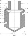
Figure 5 shows a cross-sectional view along an axial plane of theimpeller hub 34.Figure 5 clearly shows that the impeller hub may comprise afirst part 40 and asecond part 41, wherein the first andsecond parts figure 5 thefirst part 40 is configured for being attached to thetubular shaft 4, and thesecond part 41 is configured to be free from connections to themixing tank 1 for enabling simplified cleaning of themixing tank 1 andagitator arrangement 2. - However, in alternative embodiments (not shown) of the
agitator arrangement 2, thesecond part 41 of theimpeller hub 34, or any other part of theagitator arrangement 2, may have connection arrangement for rotatable connecting the rotatablehollow haft 4 of theagitator arrangement 2 to a bearing support for rotatably attaching thesecond part 41 to themixing tank 1. Such additional fastening of theagitator arrangement 2 may be necessary for avoiding too large bending motion of the rotatablehollow shaft 4 during rotation of the first andsecond impellers - If a
first end region 14 of therotatable shaft 4 is attached to an upper side of themixing tank 1 and a second end region of therotatable shaft 4 is attached to a lower side of themixing tank 1, the agitator arrangement may comprise at least oneopening 50 in asecond part 41 of thehub 34 for spraying cleaning liquid on a bottom bearing support of theagitator arrangement 2 and/or bottom of themixing tank 1. - In the example embodiment of
figure 5 the first andsecond parts weld seam 42. Manufacturing of the second impeller in twoparts openings 9. - Moreover, the
second impeller 34 further has a more modular design wherein a single type offirst part 40 may be connected with various different types ofsecond parts 41, for example for enabling attachment to various types and sizes of impeller blades to theimpeller hub 34. - In the example embodiment of
figure 5 , the plurality ofopenings 9 are located in thefirst part 40 and the impeller blades are configured to be attached inslits 56 made in the sidewall of thesecond part 41. - In detail, the
first part 40 of theimpeller hub 34 may for example, on a first axial side, have asleeve section 57 facing thesecond section 24 of thetubular shaft 4, and being configured be being attached to saidsecond section 24. Thefirst part 40 of theimpeller hub 43 may further, on a second axial side located opposite to the first axial side, have aflange section 58 that extends radially outwards from thesleeve section 57. - The
openings 9 for spraying cleaning liquid on thefirst impeller 8 may be located in theflange section 58 of thefirst part 40 of thesecond impeller 7. - In addition, an
axial orientation 60 of the plurality of openings, respectively, defines aninclination angle 43 of 1- 45 degrees, specifically 1-10 degrees, and more specifically 2-5 degrees, with respect to theaxial direction 5 of the rotatablehollow shaft 4. These ranges of theinclination angle 43 has shown to provide good results in terms of cleaning effect of the first impeller. - For enabling simplified manufacturing of the
openings 9, anaxial orientation 60 of the plurality ofopenings 9, respectively, define anangle 44 of about 90 degrees with respect to a plane of aninterior surface 45 of theimpeller hub 34 at a location of eachcorresponding opening 9. In other words, upon forming theopenings 9, for example by drilling the openings from the inner side of thehub 34, it is advantageous if thesurface 45 at the area of theopening 9 is substantially perpendicular to the axial orientation of eachopening 9, because thereby the risk that the top edge of the drill drifts away from a desired drilling location. Drilling an opening at an inclined angle with respect to a surface is significantly more difficult than drilling an opening at a straight angle to the surface. - Moreover, the modular design of the
hub 34 enables drilling from the inside of thehub 34 before the first andsecond parts - The
second part 41 of theimpeller hub 43 may have a substantially cylindrical shape, and one axial side of thesecond part 41 may be fastened to the radially outer edge of theflange section 58 of thefirst part 40 of thehub 34. -
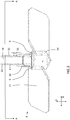
Figure 6 shows a side view of thesecond impeller 8. As briefly mentioned above, thesecond impeller 8 may compriseadditional openings 70 for eachimpeller blade 31 of thesecond impeller 8 and configured for spraying a cleaning liquid on theimpeller blades 31 of thesecond impeller 8. - The
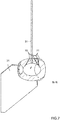
flow passages 71 of threeadditional openings 70 are clearly shown infigure 7 , which shows a sectional view along section N-N offigure 7 . - Although the
agitator arrangement 2 according to the disclosure has been mainly described with reference to a first and asecond impeller agitator arrangement 2 may equally be equipped with a third impeller secured to the rotatablehollow shaft 4 at a third axial position. The third impeller may for example comprise a plurality of openings configured for spraying a cleaning liquid on the first and/or second impeller for cleaning the first and/or second impeller. Alternatively, the third impeller may be free from openings configured for spraying a cleaning liquid. Also yet further impellers are possible. - Although the disclosure has been described in relation to specific combinations of components, it should be readily appreciated that the components may be combined in other configurations as well which is clear for the skilled person when studying the present application. Thus, the above description of the example embodiments of the present disclosure and the accompanying drawings are to be regarded as a non-limiting example of the disclosure and the scope of protection is defined by the appended claims. Any reference sign in the claims should not be construed as limiting the scope.
- The use of the word "a" or "an" in the specification may mean "one," but it is also consistent with the meaning of "one or more" or "at least one." The term "about" means, in general, the stated value plus or minus 10%, or more specifically plus or minus 5%. The use of the term "or" in the claims is used to mean "and/or" unless explicitly indicated to refer to alternatives only.
- The terms "comprise", "comprises" "comprising", "have", "has", "having", "include", "includes", "including" are open-ended linking verbs. As a result, a method or device that "comprises", "has" or "includes" for example one or more steps or elements, possesses those one or more steps or elements, but is not limited to possessing only those one or more elements.
Claims (15)
- Agitator arrangement (2) for mixing a liquid in a mixing tank (1) and for cleaning the mixing tank (1), the agitator arrangement (2) comprising:a rotatable hollow shaft (4) extending in an axial direction (5),a first impeller (7) secured to the shaft (4) at a first axial position,a second impeller (8) secured to the shaft (4) at a second axial position,wherein the second impeller (8) comprises a plurality of openings (9) configured for spraying a cleaning liquid on the first impeller (7) for cleaning the first impeller (7).
- Agitator arrangement according to claim 1, wherein the second impeller (8) includes an impeller hub (34) and impeller blades (31) secured to the impeller hub (34), and wherein the plurality of openings (9) are located in the impeller hub (34).
- Agitator arrangement according to any one of the preceding claims, wherein the second impeller (8) comprises at least 4, specifically at least 6, more specifically at least 8 and even more specifically at least 16 openings (9) configured for spraying a cleaning liquid on the first impeller (7).
- Agitator arrangement according to any one of the preceding claims, wherein the agitator arrangement (2) comprises a flow path (19) from a first end region (14) of the rotatable hollow shaft (4) to the plurality of openings (9), such that pressurized cleaning liquid supplied at the first end region (14) of the rotatable hollow shaft (4) may be sprayed out at the plurality of openings (9).
- Agitator arrangement according to any one of the preceding claims, wherein the plurality of openings (9) have a substantially cylindrical shape with a diameter of 1 - 4 mm, and specifically of 1.5 - 3 mm.
- Agitator arrangement according to any one of the preceding claims, wherein an axial orientation (60) of the plurality of openings (9), respectively, define an inclination angle (43) of 1- 45 degrees, specifically 1-10 degrees, and more specifically 2-5 degrees, with respect to the axial direction (5) of the rotatable hollow shaft (4).
- Agitator arrangement according to any one of the preceding claims, wherein a centre of an outlet of the plurality of openings (9), respectively, is located a distance (33) of 10 - 50 mm from an exterior surface (32) of the rotatable hollow shaft (4), as seen in a direction (6) perpendicular to the axial direction (5) of the rotatable hollow shaft (4).
- Agitator arrangement according to any one of the preceding claims 2 - 7, wherein an axial orientation (60) of the plurality of openings (9), respectively, define an angle (44) of about 90 degrees with respect to a plane of an interior surface (45) of the impeller hub (34) at a location of each corresponding opening (9).
- Agitator arrangement according to any one of the preceding claims 2 - 8, wherein the impeller hub (34) comprises a first part (40) and a second part (41), wherein the first and second parts (40, 41) are attached to each other, and wherein the plurality of openings (9) are located in the first part (40) and the impeller blades (31) are attached to the second part (41).
- Agitator arrangement according to any one of the preceding claims, wherein a distance (21) between the first axial position and the second axial position is 400 - 4000 mm, specifically 500 - 3000 mm, in the axial direction (5) of the rotatable hollow shaft (4).
- Agitator arrangement according to any one of the preceding claims, wherein the rotatable hollow shaft (4) comprises one or more first shaft sections (22, 23) extending from the first end region (14) of the rotatable shaft (4) to a first axial end (25) of the first impeller (7), and a second shaft section (24) extending from a second axial end (26) of the first impeller (7) to a first axial end (27) of the second impeller (8).
- Agitator arrangement according to any one of the preceding claims, wherein the first impeller (7) is free from openings configured for spraying a cleaning liquid.
- Agitator arrangement according to any one of the preceding claims, wherein the second impeller (8) further comprises at least one additional opening (70) for each blade (31) of the second impeller (8) and configured for spraying a cleaning liquid on the blades (31) of the second impeller (8).
- Agitator arrangement according to any one of the preceding claims, further comprising a third impeller secured to the shaft (4) at a third axial position, wherein- the third impeller comprises a plurality of openings configured for spraying a cleaning liquid on the first and/or second impeller (7, 8) for cleaning the first and/or second impeller (7, 8), or- the third impeller is free from openings configured for spraying a cleaning liquid.
- Mixing tank including an agitator arrangement according to any one of the preceding claims, wherein the first impeller (7) is located above the second impeller (8).
Priority Applications (2)
| Application Number | Priority Date | Filing Date | Title |
|---|---|---|---|
| EP18177890.3A EP3581262B1 (en) | 2018-06-15 | 2018-06-15 | Agitator arrangement |
| PCT/EP2019/062780 WO2019238356A1 (en) | 2018-06-15 | 2019-05-17 | Agitator arrangement |
Applications Claiming Priority (1)
| Application Number | Priority Date | Filing Date | Title |
|---|---|---|---|
| EP18177890.3A EP3581262B1 (en) | 2018-06-15 | 2018-06-15 | Agitator arrangement |
Publications (2)
| Publication Number | Publication Date |
|---|---|
| EP3581262A1 true EP3581262A1 (en) | 2019-12-18 |
| EP3581262B1 EP3581262B1 (en) | 2021-11-17 |
Family
ID=62684646
Family Applications (1)
| Application Number | Title | Priority Date | Filing Date |
|---|---|---|---|
| EP18177890.3A Active EP3581262B1 (en) | 2018-06-15 | 2018-06-15 | Agitator arrangement |
Country Status (2)
| Country | Link |
|---|---|
| EP (1) | EP3581262B1 (en) |
| WO (1) | WO2019238356A1 (en) |
Cited By (2)
| Publication number | Priority date | Publication date | Assignee | Title |
|---|---|---|---|---|
| CN111821888A (en) * | 2020-07-30 | 2020-10-27 | 陶伟 | Automatic fertilizer and water mixing device with good cleaning capacity |
| CN112007554A (en) * | 2020-08-14 | 2020-12-01 | 佛山职业技术学院 | Water injection agitating unit for food processing |
Families Citing this family (3)
| Publication number | Priority date | Publication date | Assignee | Title |
|---|---|---|---|---|
| CN112372871B (en) * | 2020-10-22 | 2022-07-01 | 安徽美高美高分子材料有限公司 | Inferior gram force board raw materials mixing stirring device |
| CN113865330B (en) * | 2021-10-09 | 2022-10-11 | 重庆医药高等专科学校 | A sterilizing and drying machine |
| CN116919201A (en) * | 2022-03-30 | 2023-10-24 | 广东美的生活电器制造有限公司 | Food processor and control method thereof |
Citations (4)
| Publication number | Priority date | Publication date | Assignee | Title |
|---|---|---|---|---|
| JPH09117654A (en) * | 1995-10-24 | 1997-05-06 | Ishikawajima Harima Heavy Ind Co Ltd | Stirring tank cleaning device |
| JP2015096250A (en) * | 2013-11-15 | 2015-05-21 | 株式会社神鋼環境ソリューション | Method of removing residue from stirrer of methane fermentation tank and methane fermentation tank allowing easy removal of residue from stirrer |
| CN206980591U (en) * | 2017-07-27 | 2018-02-09 | 浙江长江搅拌设备有限公司 | A kind of self-cleaning mixer |
| CN207169685U (en) * | 2017-05-06 | 2018-04-03 | 浙江百辰食品科技有限公司 | A kind of chemical industry reactor |
-
2018
- 2018-06-15 EP EP18177890.3A patent/EP3581262B1/en active Active
-
2019
- 2019-05-17 WO PCT/EP2019/062780 patent/WO2019238356A1/en not_active Ceased
Patent Citations (4)
| Publication number | Priority date | Publication date | Assignee | Title |
|---|---|---|---|---|
| JPH09117654A (en) * | 1995-10-24 | 1997-05-06 | Ishikawajima Harima Heavy Ind Co Ltd | Stirring tank cleaning device |
| JP2015096250A (en) * | 2013-11-15 | 2015-05-21 | 株式会社神鋼環境ソリューション | Method of removing residue from stirrer of methane fermentation tank and methane fermentation tank allowing easy removal of residue from stirrer |
| CN207169685U (en) * | 2017-05-06 | 2018-04-03 | 浙江百辰食品科技有限公司 | A kind of chemical industry reactor |
| CN206980591U (en) * | 2017-07-27 | 2018-02-09 | 浙江长江搅拌设备有限公司 | A kind of self-cleaning mixer |
Cited By (2)
| Publication number | Priority date | Publication date | Assignee | Title |
|---|---|---|---|---|
| CN111821888A (en) * | 2020-07-30 | 2020-10-27 | 陶伟 | Automatic fertilizer and water mixing device with good cleaning capacity |
| CN112007554A (en) * | 2020-08-14 | 2020-12-01 | 佛山职业技术学院 | Water injection agitating unit for food processing |
Also Published As
| Publication number | Publication date |
|---|---|
| WO2019238356A1 (en) | 2019-12-19 |
| EP3581262B1 (en) | 2021-11-17 |
Similar Documents
| Publication | Publication Date | Title |
|---|---|---|
| EP3581262B1 (en) | Agitator arrangement | |
| EP3216527B1 (en) | Liquid ejection apparatus | |
| US10960415B1 (en) | Spray nozzle and method | |
| US9987668B2 (en) | Liquid ejection system with nozzle having two outlets | |
| CN108472655B (en) | Sanitary rotary pot type cleaning device | |
| AU2007207929B2 (en) | Device for absorption of gas or vapour in a liquid and method for reintroducing vapour or gas in the liquid from which the vapour or gas originates | |
| US20020176322A1 (en) | Sanitary mixing assembly for vessels and tanks | |
| US5620250A (en) | Jet mixer having a self-centering liquid bearing hub arrangement | |
| JP2017104777A (en) | Rotary spray nozzle | |
| US6997601B2 (en) | Agitator with removable blades for sanitary tank | |
| JP6754783B2 (en) | Swirling device with sterile air flow | |
| EP2378168B1 (en) | Clean-in-place seal assembly | |
| CN108201329A (en) | Water inlet component, material cleaning device, anti-overflow component and cooking apparatus | |
| US7329065B2 (en) | Coupling assembly and method for connecting and disconnecting a shaft assembly | |
| EP3581263B1 (en) | Agitator arrangement | |
| KR20220027890A (en) | Pump unit with temperature controllable casing part | |
| KR101896159B1 (en) | Air bubble generator of fermentation tank | |
| US4720195A (en) | Agitator | |
| JP3745240B2 (en) | Shaft seal | |
| US5810559A (en) | Reactor coolant pump safety shroud | |
| US20220410227A1 (en) | Cleaning device for sanitary processing equipment and a method of manufacturing the cleaning device | |
| KR101376974B1 (en) | Bubble feeding tube and bubble cutting tube of ballast water treatment apparatus | |
| US1232128A (en) | Pasteurizer and ripener. | |
| US507392A (en) | Aerating apparatus | |
| JP5419870B6 (en) | Injection tube with injection tube and this type of injection tube |
Legal Events
| Date | Code | Title | Description |
|---|---|---|---|
| PUAI | Public reference made under article 153(3) epc to a published international application that has entered the european phase |
Free format text: ORIGINAL CODE: 0009012 |
|
| STAA | Information on the status of an ep patent application or granted ep patent |
Free format text: STATUS: REQUEST FOR EXAMINATION WAS MADE |
|
| 17P | Request for examination filed |
Effective date: 20180615 |
|
| AK | Designated contracting states |
Kind code of ref document: A1 Designated state(s): AL AT BE BG CH CY CZ DE DK EE ES FI FR GB GR HR HU IE IS IT LI LT LU LV MC MK MT NL NO PL PT RO RS SE SI SK SM TR |
|
| AX | Request for extension of the european patent |
Extension state: BA ME |
|
| STAA | Information on the status of an ep patent application or granted ep patent |
Free format text: STATUS: EXAMINATION IS IN PROGRESS |
|
| 17Q | First examination report despatched |
Effective date: 20201028 |
|
| GRAP | Despatch of communication of intention to grant a patent |
Free format text: ORIGINAL CODE: EPIDOSNIGR1 |
|
| STAA | Information on the status of an ep patent application or granted ep patent |
Free format text: STATUS: GRANT OF PATENT IS INTENDED |
|
| INTG | Intention to grant announced |
Effective date: 20210713 |
|
| GRAS | Grant fee paid |
Free format text: ORIGINAL CODE: EPIDOSNIGR3 |
|
| GRAA | (expected) grant |
Free format text: ORIGINAL CODE: 0009210 |
|
| STAA | Information on the status of an ep patent application or granted ep patent |
Free format text: STATUS: THE PATENT HAS BEEN GRANTED |
|
| AK | Designated contracting states |
Kind code of ref document: B1 Designated state(s): AL AT BE BG CH CY CZ DE DK EE ES FI FR GB GR HR HU IE IS IT LI LT LU LV MC MK MT NL NO PL PT RO RS SE SI SK SM TR |
|
| REG | Reference to a national code |
Ref country code: GB Ref legal event code: FG4D |
|
| REG | Reference to a national code |
Ref country code: DE Ref legal event code: R079 Ref document number: 602018026717 Country of ref document: DE Free format text: PREVIOUS MAIN CLASS: B01F0007000000 Ipc: B01F0027000000 |
|
| REG | Reference to a national code |
Ref country code: IE Ref legal event code: FG4D |
|
| REG | Reference to a national code |
Ref country code: DE Ref legal event code: R096 Ref document number: 602018026717 Country of ref document: DE |
|
| REG | Reference to a national code |
Ref country code: AT Ref legal event code: REF Ref document number: 1447592 Country of ref document: AT Kind code of ref document: T Effective date: 20211215 |
|
| REG | Reference to a national code |
Ref country code: LT Ref legal event code: MG9D |
|
| REG | Reference to a national code |
Ref country code: NL Ref legal event code: MP Effective date: 20211117 |
|
| REG | Reference to a national code |
Ref country code: AT Ref legal event code: MK05 Ref document number: 1447592 Country of ref document: AT Kind code of ref document: T Effective date: 20211117 |
|
| PG25 | Lapsed in a contracting state [announced via postgrant information from national office to epo] |
Ref country code: RS Free format text: LAPSE BECAUSE OF FAILURE TO SUBMIT A TRANSLATION OF THE DESCRIPTION OR TO PAY THE FEE WITHIN THE PRESCRIBED TIME-LIMIT Effective date: 20211117 Ref country code: LT Free format text: LAPSE BECAUSE OF FAILURE TO SUBMIT A TRANSLATION OF THE DESCRIPTION OR TO PAY THE FEE WITHIN THE PRESCRIBED TIME-LIMIT Effective date: 20211117 Ref country code: FI Free format text: LAPSE BECAUSE OF FAILURE TO SUBMIT A TRANSLATION OF THE DESCRIPTION OR TO PAY THE FEE WITHIN THE PRESCRIBED TIME-LIMIT Effective date: 20211117 Ref country code: BG Free format text: LAPSE BECAUSE OF FAILURE TO SUBMIT A TRANSLATION OF THE DESCRIPTION OR TO PAY THE FEE WITHIN THE PRESCRIBED TIME-LIMIT Effective date: 20220217 Ref country code: AT Free format text: LAPSE BECAUSE OF FAILURE TO SUBMIT A TRANSLATION OF THE DESCRIPTION OR TO PAY THE FEE WITHIN THE PRESCRIBED TIME-LIMIT Effective date: 20211117 |
|
| PG25 | Lapsed in a contracting state [announced via postgrant information from national office to epo] |
Ref country code: IS Free format text: LAPSE BECAUSE OF FAILURE TO SUBMIT A TRANSLATION OF THE DESCRIPTION OR TO PAY THE FEE WITHIN THE PRESCRIBED TIME-LIMIT Effective date: 20220317 Ref country code: SE Free format text: LAPSE BECAUSE OF FAILURE TO SUBMIT A TRANSLATION OF THE DESCRIPTION OR TO PAY THE FEE WITHIN THE PRESCRIBED TIME-LIMIT Effective date: 20211117 Ref country code: PT Free format text: LAPSE BECAUSE OF FAILURE TO SUBMIT A TRANSLATION OF THE DESCRIPTION OR TO PAY THE FEE WITHIN THE PRESCRIBED TIME-LIMIT Effective date: 20220317 Ref country code: PL Free format text: LAPSE BECAUSE OF FAILURE TO SUBMIT A TRANSLATION OF THE DESCRIPTION OR TO PAY THE FEE WITHIN THE PRESCRIBED TIME-LIMIT Effective date: 20211117 Ref country code: NO Free format text: LAPSE BECAUSE OF FAILURE TO SUBMIT A TRANSLATION OF THE DESCRIPTION OR TO PAY THE FEE WITHIN THE PRESCRIBED TIME-LIMIT Effective date: 20220217 Ref country code: NL Free format text: LAPSE BECAUSE OF FAILURE TO SUBMIT A TRANSLATION OF THE DESCRIPTION OR TO PAY THE FEE WITHIN THE PRESCRIBED TIME-LIMIT Effective date: 20211117 Ref country code: LV Free format text: LAPSE BECAUSE OF FAILURE TO SUBMIT A TRANSLATION OF THE DESCRIPTION OR TO PAY THE FEE WITHIN THE PRESCRIBED TIME-LIMIT Effective date: 20211117 Ref country code: HR Free format text: LAPSE BECAUSE OF FAILURE TO SUBMIT A TRANSLATION OF THE DESCRIPTION OR TO PAY THE FEE WITHIN THE PRESCRIBED TIME-LIMIT Effective date: 20211117 Ref country code: GR Free format text: LAPSE BECAUSE OF FAILURE TO SUBMIT A TRANSLATION OF THE DESCRIPTION OR TO PAY THE FEE WITHIN THE PRESCRIBED TIME-LIMIT Effective date: 20220218 Ref country code: ES Free format text: LAPSE BECAUSE OF FAILURE TO SUBMIT A TRANSLATION OF THE DESCRIPTION OR TO PAY THE FEE WITHIN THE PRESCRIBED TIME-LIMIT Effective date: 20211117 |
|
| PG25 | Lapsed in a contracting state [announced via postgrant information from national office to epo] |
Ref country code: SM Free format text: LAPSE BECAUSE OF FAILURE TO SUBMIT A TRANSLATION OF THE DESCRIPTION OR TO PAY THE FEE WITHIN THE PRESCRIBED TIME-LIMIT Effective date: 20211117 Ref country code: SK Free format text: LAPSE BECAUSE OF FAILURE TO SUBMIT A TRANSLATION OF THE DESCRIPTION OR TO PAY THE FEE WITHIN THE PRESCRIBED TIME-LIMIT Effective date: 20211117 Ref country code: RO Free format text: LAPSE BECAUSE OF FAILURE TO SUBMIT A TRANSLATION OF THE DESCRIPTION OR TO PAY THE FEE WITHIN THE PRESCRIBED TIME-LIMIT Effective date: 20211117 Ref country code: EE Free format text: LAPSE BECAUSE OF FAILURE TO SUBMIT A TRANSLATION OF THE DESCRIPTION OR TO PAY THE FEE WITHIN THE PRESCRIBED TIME-LIMIT Effective date: 20211117 Ref country code: DK Free format text: LAPSE BECAUSE OF FAILURE TO SUBMIT A TRANSLATION OF THE DESCRIPTION OR TO PAY THE FEE WITHIN THE PRESCRIBED TIME-LIMIT Effective date: 20211117 Ref country code: CZ Free format text: LAPSE BECAUSE OF FAILURE TO SUBMIT A TRANSLATION OF THE DESCRIPTION OR TO PAY THE FEE WITHIN THE PRESCRIBED TIME-LIMIT Effective date: 20211117 |
|
| REG | Reference to a national code |
Ref country code: DE Ref legal event code: R097 Ref document number: 602018026717 Country of ref document: DE |
|
| PLBE | No opposition filed within time limit |
Free format text: ORIGINAL CODE: 0009261 |
|
| STAA | Information on the status of an ep patent application or granted ep patent |
Free format text: STATUS: NO OPPOSITION FILED WITHIN TIME LIMIT |
|
| 26N | No opposition filed |
Effective date: 20220818 |
|
| PG25 | Lapsed in a contracting state [announced via postgrant information from national office to epo] |
Ref country code: AL Free format text: LAPSE BECAUSE OF FAILURE TO SUBMIT A TRANSLATION OF THE DESCRIPTION OR TO PAY THE FEE WITHIN THE PRESCRIBED TIME-LIMIT Effective date: 20211117 |
|
| PG25 | Lapsed in a contracting state [announced via postgrant information from national office to epo] |
Ref country code: SI Free format text: LAPSE BECAUSE OF FAILURE TO SUBMIT A TRANSLATION OF THE DESCRIPTION OR TO PAY THE FEE WITHIN THE PRESCRIBED TIME-LIMIT Effective date: 20211117 |
|
| PG25 | Lapsed in a contracting state [announced via postgrant information from national office to epo] |
Ref country code: MC Free format text: LAPSE BECAUSE OF FAILURE TO SUBMIT A TRANSLATION OF THE DESCRIPTION OR TO PAY THE FEE WITHIN THE PRESCRIBED TIME-LIMIT Effective date: 20211117 |
|
| REG | Reference to a national code |
Ref country code: CH Ref legal event code: PL |
|
| PG25 | Lapsed in a contracting state [announced via postgrant information from national office to epo] |
Ref country code: LU Free format text: LAPSE BECAUSE OF NON-PAYMENT OF DUE FEES Effective date: 20220615 Ref country code: LI Free format text: LAPSE BECAUSE OF NON-PAYMENT OF DUE FEES Effective date: 20220630 Ref country code: IE Free format text: LAPSE BECAUSE OF NON-PAYMENT OF DUE FEES Effective date: 20220615 Ref country code: FR Free format text: LAPSE BECAUSE OF NON-PAYMENT OF DUE FEES Effective date: 20220630 Ref country code: CH Free format text: LAPSE BECAUSE OF NON-PAYMENT OF DUE FEES Effective date: 20220630 |
|
| PG25 | Lapsed in a contracting state [announced via postgrant information from national office to epo] |
Ref country code: IT Free format text: LAPSE BECAUSE OF FAILURE TO SUBMIT A TRANSLATION OF THE DESCRIPTION OR TO PAY THE FEE WITHIN THE PRESCRIBED TIME-LIMIT Effective date: 20211117 |
|
| P01 | Opt-out of the competence of the unified patent court (upc) registered |
Effective date: 20230421 |
|
| PG25 | Lapsed in a contracting state [announced via postgrant information from national office to epo] |
Ref country code: MK Free format text: LAPSE BECAUSE OF FAILURE TO SUBMIT A TRANSLATION OF THE DESCRIPTION OR TO PAY THE FEE WITHIN THE PRESCRIBED TIME-LIMIT Effective date: 20211117 Ref country code: CY Free format text: LAPSE BECAUSE OF FAILURE TO SUBMIT A TRANSLATION OF THE DESCRIPTION OR TO PAY THE FEE WITHIN THE PRESCRIBED TIME-LIMIT Effective date: 20211117 |
|
| PG25 | Lapsed in a contracting state [announced via postgrant information from national office to epo] |
Ref country code: HU Free format text: LAPSE BECAUSE OF FAILURE TO SUBMIT A TRANSLATION OF THE DESCRIPTION OR TO PAY THE FEE WITHIN THE PRESCRIBED TIME-LIMIT; INVALID AB INITIO Effective date: 20180615 |
|
| PG25 | Lapsed in a contracting state [announced via postgrant information from national office to epo] |
Ref country code: TR Free format text: LAPSE BECAUSE OF FAILURE TO SUBMIT A TRANSLATION OF THE DESCRIPTION OR TO PAY THE FEE WITHIN THE PRESCRIBED TIME-LIMIT Effective date: 20211117 |
|
| PG25 | Lapsed in a contracting state [announced via postgrant information from national office to epo] |
Ref country code: MT Free format text: LAPSE BECAUSE OF FAILURE TO SUBMIT A TRANSLATION OF THE DESCRIPTION OR TO PAY THE FEE WITHIN THE PRESCRIBED TIME-LIMIT Effective date: 20211117 |
|
| PGFP | Annual fee paid to national office [announced via postgrant information from national office to epo] |
Ref country code: DE Payment date: 20250402 Year of fee payment: 8 |
|
| PGFP | Annual fee paid to national office [announced via postgrant information from national office to epo] |
Ref country code: GB Payment date: 20250401 Year of fee payment: 8 |
|
| PGFP | Annual fee paid to national office [announced via postgrant information from national office to epo] |
Ref country code: BE Payment date: 20250410 Year of fee payment: 8 |