EP3581085A1 - Endoscope cleaning tool - Google Patents
Endoscope cleaning tool Download PDFInfo
- Publication number
- EP3581085A1 EP3581085A1 EP18751628.1A EP18751628A EP3581085A1 EP 3581085 A1 EP3581085 A1 EP 3581085A1 EP 18751628 A EP18751628 A EP 18751628A EP 3581085 A1 EP3581085 A1 EP 3581085A1
- Authority
- EP
- European Patent Office
- Prior art keywords
- endoscope
- dirt
- cleaning device
- tube
- pseudo
- Prior art date
- Legal status (The legal status is an assumption and is not a legal conclusion. Google has not performed a legal analysis and makes no representation as to the accuracy of the status listed.)
- Granted
Links
Images

Classifications
-
- A—HUMAN NECESSITIES
- A46—BRUSHWARE
- A46B—BRUSHES
- A46B5/00—Brush bodies; Handles integral with brushware
- A46B5/06—Brush bodies; Handles integral with brushware in the form of tapes, chains, flexible shafts, springs, mats or the like
-
- A—HUMAN NECESSITIES
- A61—MEDICAL OR VETERINARY SCIENCE; HYGIENE
- A61B—DIAGNOSIS; SURGERY; IDENTIFICATION
- A61B1/00—Instruments for performing medical examinations of the interior of cavities or tubes of the body by visual or photographical inspection, e.g. endoscopes; Illuminating arrangements therefor
- A61B1/12—Instruments for performing medical examinations of the interior of cavities or tubes of the body by visual or photographical inspection, e.g. endoscopes; Illuminating arrangements therefor with cooling or rinsing arrangements
-
- A—HUMAN NECESSITIES
- A61—MEDICAL OR VETERINARY SCIENCE; HYGIENE
- A61B—DIAGNOSIS; SURGERY; IDENTIFICATION
- A61B1/00—Instruments for performing medical examinations of the interior of cavities or tubes of the body by visual or photographical inspection, e.g. endoscopes; Illuminating arrangements therefor
- A61B1/12—Instruments for performing medical examinations of the interior of cavities or tubes of the body by visual or photographical inspection, e.g. endoscopes; Illuminating arrangements therefor with cooling or rinsing arrangements
- A61B1/121—Instruments for performing medical examinations of the interior of cavities or tubes of the body by visual or photographical inspection, e.g. endoscopes; Illuminating arrangements therefor with cooling or rinsing arrangements provided with means for cleaning post-use
- A61B1/122—Instruments for performing medical examinations of the interior of cavities or tubes of the body by visual or photographical inspection, e.g. endoscopes; Illuminating arrangements therefor with cooling or rinsing arrangements provided with means for cleaning post-use using cleaning tools, e.g. brushes
-
- A—HUMAN NECESSITIES
- A46—BRUSHWARE
- A46B—BRUSHES
- A46B9/00—Arrangements of the bristles in the brush body
- A46B9/005—Arrangements of the bristles in the brush body where the brushing material is not made of bristles, e.g. sponge, rubber or paper
-
- A—HUMAN NECESSITIES
- A46—BRUSHWARE
- A46B—BRUSHES
- A46B9/00—Arrangements of the bristles in the brush body
- A46B9/06—Arrangement of mixed bristles or tufts of bristles, e.g. wire, fibre, rubber
-
- A—HUMAN NECESSITIES
- A61—MEDICAL OR VETERINARY SCIENCE; HYGIENE
- A61L—METHODS OR APPARATUS FOR STERILISING MATERIALS OR OBJECTS IN GENERAL; DISINFECTION, STERILISATION OR DEODORISATION OF AIR; CHEMICAL ASPECTS OF BANDAGES, DRESSINGS, ABSORBENT PADS OR SURGICAL ARTICLES; MATERIALS FOR BANDAGES, DRESSINGS, ABSORBENT PADS OR SURGICAL ARTICLES
- A61L2/00—Disinfection or sterilisation of materials or objects, in general; Accessories therefor
- A61L2/16—Disinfection or sterilisation of materials or objects, in general; Accessories therefor using chemical substances
-
- A—HUMAN NECESSITIES
- A46—BRUSHWARE
- A46B—BRUSHES
- A46B2200/00—Brushes characterized by their functions, uses or applications
- A46B2200/30—Brushes for cleaning or polishing
- A46B2200/3013—Brushes for cleaning the inside or the outside of tubes
-
- A—HUMAN NECESSITIES
- A61—MEDICAL OR VETERINARY SCIENCE; HYGIENE
- A61B—DIAGNOSIS; SURGERY; IDENTIFICATION
- A61B90/00—Instruments, implements or accessories specially adapted for surgery or diagnosis and not covered by any of the groups A61B1/00 - A61B50/00, e.g. for luxation treatment or for protecting wound edges
- A61B90/70—Cleaning devices specially adapted for surgical instruments
- A61B2090/701—Cleaning devices specially adapted for surgical instruments for flexible tubular instruments, e.g. endoscopes
-
- A—HUMAN NECESSITIES
- A61—MEDICAL OR VETERINARY SCIENCE; HYGIENE
- A61L—METHODS OR APPARATUS FOR STERILISING MATERIALS OR OBJECTS IN GENERAL; DISINFECTION, STERILISATION OR DEODORISATION OF AIR; CHEMICAL ASPECTS OF BANDAGES, DRESSINGS, ABSORBENT PADS OR SURGICAL ARTICLES; MATERIALS FOR BANDAGES, DRESSINGS, ABSORBENT PADS OR SURGICAL ARTICLES
- A61L2103/00—Materials or objects being the target of disinfection or sterilisation
- A61L2103/15—Laboratory, medical or dentistry appliances, e.g. catheters or sharps
Definitions
- the present invention relates to a cleaning device for use with medical devices, and more specifically to a cleaning device for cleaning endoscopes.
- an endoscope typically becomes soiled with biological and other materials from a patient body (e.g., biliary fluids, saliva, feces, blood, pieces of tissue, etc.) and potentially from other devices or materials used in conjunction with the endoscope. Because endoscopes are used multiple times, it is important that they are completely cleaned between uses to avoid cross-contamination between devices used with them, and between different patients.
- a patient body e.g., biliary fluids, saliva, feces, blood, pieces of tissue, etc.
- a typical cleaning regimen for cleansing of an endoscope includes wiping it down with a detergent (such as an enzymatic detergent), then soaking it in and flushing it with a same or different detergent, water, and air, and then finally drying it for sterilization.
- a detergent such as an enzymatic detergent
- the detergent provides for chemical cleaning and the flushing provides for mechanical cleaning.
- Patent Literature 1 by Kritzler discloses a sponge device for spreading luminal contamination of an endoscope into a substantially uniform film on the luminal surface so that enzymatic cleaners can more efficiently and uniformly digest the contaminating material.
- the sponge device disclosed in the literature is not configured to provide the mechanical force needed to actually remove adhering luminal contaminants, but rather spreads them uniformly.
- Patent Literature 2 proposes a cleaning device for automatic cleaning by brushing.
- the cleaning device disclosed in the literature has a plurality of brushes that are movably connected to each other via a flexible yarn, such as a fiber yarn.
- the cleaning device is inserted into the lumen of an endoscope and pushed forward by the pressure of cleaning water for brush cleaning of the inner surface of the lumen of the endoscope.
- the tips of the bristles lightly and irregularly rub the inner surface of the lumen.
- Relatively easily removable dirt adhering to the inner surface of the lumen such as secretion (e.g., mucus), blood, tissue fragments, is removed by the cleaning, but microorganisms, such as viruses, bacteria and others, are difficult to remove.
- the plurality of connected brushes may not contact the entire surface of the inner wall of the lumen, in particular, the inner surface with a scratch and/or the inner wall of the bending section or of the connecting section of different parts.
- Patent Literature 3 proposes a porous body for cleaning an endoscopic lumen for insertion of an endoscopic accessory.
- the porous body is an approximately spherical porous body formed of a large number of ultrafine fibers.
- the porous body is capable of swelling in the presence of an aqueous cleaning liquid so that the outer diameter of the porous body is larger than the inner diameter of the lumen to be cleaned by the porous body that has swelled.
- the porous body is also capable of being deformed for insertion into the lumen, and is movable while maintaining contact with the inner wall of the lumen with an aid of an aqueous cleaning liquid flowing through the lumen.
- the porous body disclosed in the literature requires an aqueous cleaning liquid.
- the main components of the dirt adhering to an endoscope are proteins and lipids, the porous body can only remove proteins, but not lipids.
- the present invention was made to solve the above problems, and an object of the present invention is to provide an endoscope-cleaning device that ensures effective cleaning of an endoscope.
- the inventors conducted extensive research to solve the above problems, and found that the problems are solved by the following means.
- the endoscope-cleaning device of the present invention comprises a twisted tubular body into which a long flexible core member is inserted and which comprises a weft yarn comprising microfibers, which effectively remove proteins and lipids adhering to the inner surface of an endoscope.
- the core member can be made of a flexible material.
- the core member is, for example, made of a nylon.
- nylons are available, and any type of known nylons can be employed, including Nylon 6, Nylon 11, Nylon 12, Nylon 66, etc.
- the core member preferably has an outer diameter of 1 mm to 2 mm and a length of 200 cm to 250 cm for ease of handling.
- the tubular body for accommodating the inserted core member may be a woven fabric or a knitted fabric, but is preferably a woven fabric.
- the weave for producing the woven fabric includes, for example, plain weave in which "each weft thread passes alternately over and under a warp thread and each warp thread passes alternately over and under a weft thread", twill weave in which "each weft thread does not pass alternately over and under a warp thread or vice versa, but each weft thread passes over one warp thread and then passes under two warp threads (1 ⁇ 2 twill), or each weft thread passes over one warp thread and then passes under three warp threads (1 ⁇ 3 twill) ", satin weave in which "there are a small number of floats of weft threads and only warp threads appear to lie on the surface and therefore the fabric has a glossy surface", solidly covered weave that "uses colored threads to weave a background design on another type of weave, such as a plain or satin
- the tubular body can be produced by weaving a fabric layer on one side and another fabric layer on the reverse side with the so-called hollow weave, which can produce a hollow woven fabric in which fabric layers are joined at the selvage ends.
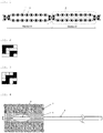
- Fig. 1 is a sectional view showing an example of a double-layer woven fabric as an embodiment of the tubular body.
- Fig. 2 is a weave diagram of the section A of the fabric of Fig. 1.
- Fig. 3 is a weave diagram of the section B of the fabric of Fig. 1.
- Fig. 1 contains a warp yarn 1, a weft yarn 2, a face fabric 3 on one side of the tubular body, and a back fabric 4 on the reverse side of the tubular body.
- the long flexible core member can be inserted between the face fabric 3 on one side of the tubular body and the back fabric 4 on the reverse side of the tubular body as shown in Fig. 1 .
- the weft yarn preferably contains a microfiber yarn.
- the microfiber yarn used in the present invention is preferably an ultrafine fiber of about 2 to 8 ⁇ m in diameter.
- an oil film has a thickness of about 1 to 2 ⁇ m, and is impossible to wipe off with ordinary fibers, whose thickness is typically about 15 ⁇ m.
- the microfiber yarn of about 2 to 8 ⁇ m in diameter used in the present invention is capable of wiping off such an oil film.
- the weft yarn may contain a different yarn other than the microfiber yarn, and the diameter of said different yarn is preferably 10 to 20 ⁇ m but is not limited thereto.
- the microfiber may be produced by direct spinning process, sea-island spinning process, split or peeling spinning process, or ply spinning process.
- the sea-island spinning process has various advantages over the other three processes.
- the sea-island spinning process can relatively easily produce any cross-sectional shape; the produced fibers are easily handled like ordinary fibers in high-order processing; and spacing between ultrafine fibers obtained after removal of the sea component is easily maintained in the woven fabric.
- the microfiber can be generated from, for example, an ultrafine fiber-generating fiber produced by melt spinning of polymers of an island component and a sea component containing a polyalkylene glycol.
- the polymer that constitutes the microfiber is, for example, polyester, polyamide, polyolefin, polyphenylene sulfide, or the like.
- polyester include polyethylene terephthalate, polybutylene terephthalate, polytrimethylene terephthalate, etc.
- polyamide include Nylon 6, Nylon 66, Nylon 12, etc.
- the sea component of the sea-island type composite fiber may be polyethylene; polypropylene; polystyrene; a polyester copolymerized with sodium sulfoisophthalate, polyethylene glycol, or the like; polylactic acid; or the like.
- a copolymerized polyester is preferred due to good spinnability, dissolvability, etc.
- the copolymerized polyester is preferably a polyester copolymerized with 5 to 10 mol% of sodium 5-sulfoisophthalate, and preferably further contains a polyalkylene glycol.
- the polyalkylene glycol may be polyethylene glycol, polypropylene glycol, polybutylene glycol, or the like.
- Polybutylene glycol is preferred because it is easy to handle, requires a reduced amount of an alkaline aqueous solution etc., and has other advantages.
- the microfiber used in the present invention may be generated from an ultrafine fiber-generating fiber as a precursor.
- the ultrafine fiber-generating fiber is, for example, a sea-island type composite fiber consisting of a sea component polymer and an island component polymer.
- the ultrafine fiber-generating fiber preferably contains a polyalkylene glycol in the sea component polymer serving as an easily dissolvable component.
- the polyalkylene glycol component preferably extends in the longitudinal direction and forms a stripe pattern.
- the mass ratio of the poorly dissolvable component (the island component polymer) relative to that of the polyester-based easily dissolvable component (the sea component polymer) is preferably 0.2 to 0.8, and is more preferably 0.3 to 0.7.
- the poorly dissolvable component is contained at a mass ratio of 0.2 or more, the amount of the polyester-based easily dissolvable component required to be removed is small, and consequently the productivity improves.
- the poorly dissolvable component is contained at a mass ratio of 0.8 or less, the splittability of the poorly dissolvable component fibers improves, and also fusion of the poorly dissolvable component fibers is prevented.
- the poorly dissolvable component is, for example, a polymer such as polyester, polyamide, polyolefin and polyphenylene sulfide.
- a polymer such as polyester, polyamide, polyolefin and polyphenylene sulfide.
- polyester include polyethylene terephthalate, polybutylene terephthalate, polytrimethylene terephthalate, etc.
- polyamide include Nylon 6, Nylon 66, Nylon 12, etc.
- the polyester-based easily dissolvable component refers to a component having 100-fold or higher solubility, preferably 200-fold or higher solubility, in a solvent such as an organic solvent or an aqueous solution such as an alkali solution, as compared with the poorly dissolvable component. Due to the 100-fold or higher difference in solubility, the poorly dissolvable component is protected from damage during the dissolving procedure, and the poorly dissolvable component is well dispersed.
- the microfiber used in the present invention can be generated from, for example, an ultrafine fiber-generating fiber.
- the ultrafine fiber-generating fiber may be a sea-island type composite fiber containing two types of thermoplastic resins having different solubilities in a solvent etc.
- the two types of thermoplastic resins serve as an island component polymer and a sea component polymer, respectively.
- the sea component polymer is removed by dissolving in a solvent etc. in post-processing, thereby converting the island component polymer into ultrafine fibers.
- the ultrafine fiber-generating fiber may be a peeling type composite fiber containing two types of thermoplastic resins that are alternately arranged in radial segments or in multilayer segments in the cross section of the fiber. The alternately arranged segments are then peeled or separated from each other so that the composite fiber is split into ultrafine fibers.
- the sea-island type composite fiber may be a sea-island type composite fiber produced by spinning alternately arranged two types of components, i.e., the sea and island components, using a die for producing sea-island type composite fibers.
- the sea-island type composite fiber may be a blended spun fiber produced by spinning mixed two types of polymers, i.e., the sea and island component polymers.
- the sea-island type composite fiber is particularly preferred because ultrafine fibers of a uniform fineness and a sufficient length are obtained.
- the tubular body is preferably twisted at 5 twists/5 cm to 15 twists/5 cm.
- the tubular body twisted at less than 5 twists/5 cm will have poor cleaning effect, whereas the tubular body twisted at more than 15 twists/5 cm will have high resistance and tends to make cleaning difficult.
- the weft yarn used was prepared as follows: a high shrinkage polyester yarn of 33 dtex and 6 filaments, serving as a core, was covered with two textured synthetic ultrafine microfiber yarns (sea-island composite type dissolution-splitting ultra-superfine polyester yarns) each of 66 dtex and 9 filaments, serving as a sheath, and then the yarn was twisted together with two polyester yarns each of 55 dtex and 24 filaments at 130 T/m.
- the warp yarns used were two textured nylon yarns each of 56 dtex and 17 filaments.
- the weft yarn and the warp yarns were used to produce a tubular double-layer woven fabric of which the center portion was woven with plain weave.
- a Nylon 6 monofilament of 1.3 mm in diameter was inserted into the tubular double-layer woven fabric. In this manner, an example of an endoscope-cleaning device of the present invention as shown in Fig. 4 was obtained.
- the tubular body made of the double-layer woven fabric is indicated by the numeral 5
- the long flexible core member, made of the Nylon 6 monofilament, inserted into the tubular body is indicated by the numeral 6
- the microfiber yarns contained in the weft yarn of the tubular body are indicated by the numeral 7.
- the long flexible core member 6 made of the Nylon 6 monofilament was bonded with the tubular body 5 by ultrasonic fusion bonding.
- one twist pitch length is indicated by P.
- the tubular body 5 is preferably provided with twisting of 5 pitches to 15 pitches per 5 cm, most preferably 8 pitches per 5 cm.
- a brush having nylon bristles of 100 ⁇ m in diameter and 5 mm in length was attached to an end of a long, round stainless steel rod of about 1.5 mm in diameter, and was used as an endoscope-cleaning device of Comparative Example.
- a polytetrafluoroethylene tube of 3 mm in inner diameter and 2 m in length was used as a tube for evaluation test.
- bovine serum albumin for preparation of pseudo-dirt, bovine serum albumin, pig mucin and pure lard were mixed at a protein: lipid ratio of about 1:1 part by weight.
- the pseudo-dirt was injected into the tube for evaluation test using a micropipette, and the tube was swung right and left 20 times to allow the pseudo-dirt to adhere to the inner surface of the tube so that the thickness of the pseudo-dirt was approximately uniform.
- the initial amount of the protein in the pseudo-dirt was determined as follows. Prior to the injection of the alkaline detergent in the above procedure, 0.5 mL (milliliters) of the pseudo-dirt adhering to the inner surface of the above tube for evaluation test was collected. The protein was quantified by the Lowry method, which is a commonly used analysis method for quantifying proteins, in which copper sulfate was added to a protein solution under alkaline conditions, then Folin-Ciocalteu reagent was added to react, and the absorbance at 750 nm was measured. The results are shown in Table 1 below as the initial amount of the protein.
- the initial amount of the lipid in the pseudo-dirt was determined as follows. Prior to the injection of the alkaline detergent in the above procedure, 5 mL of the pseudo-dirt adhering to the inner surface of the above tube for evaluation test was collected. The dirt component was extracted with a mixed solvent containing chloroform and methanol at a volumetric ratio of 2:1, and dehydration was performed to remove the solvent. The lipid was quantified by the gravimetric method. The results are shown in Table 2 below as the initial amount of the lipid.
- ATP is an essential energy substance for every organism. ATP is contained in dirt derived from microorganisms or organisms, and therefore the measurement of the amounts of ATP and AMP (adenosine monophosphate), which is a decomposition product of ATP, contained in a microbe-removing wiping cloth objectively confirms the contamination by organisms.
- the measurement is performed using, for example, a luminescent reagent containing firefly luciferase, luciferin, and pyruvate orthophosphate dikinase (PPDK). Firefly luciferase produces luminescence in the presence of ATP and luciferin. This reaction also produces AMP.
- the AMP is converted into ATP by PPDK and again subjected to the reaction with the luminescent reagent. In this manner, the luminescence corresponding to the total amount of ATP is obtained. The intensity of the luminescence is then measured with a particular measuring device to determine the degree of dirt.
- a polytetrafluoroethylene tube of 3 mm in inner diameter and 2 m in length was used as a tube for evaluation test.
- Pseudo-dirt was prepared as follows. A sewing machine oil (mineral oil) produced by Sumico Lubricant Co., Ltd. was mixed with an ATP (adenosine triphosphate) reagent produced by Wako Pure Chemical Industries, Ltd. so that the concentration of ATP was 0.001% by weight. The mixture was placed in an appropriate container, and uniformly agitated by ultrasonic vibration for 5 minutes to allow the ATP to uniformly disperse in the oil. The thus prepared mixture was used as pseudo-dirt.
- ATP adenosine triphosphate
- the endoscope-cleaning device of the present invention was inserted into the tube and then withdrawn to wipe the pseudo-dirt.
- the pseudo-dirt was allowed to adhere to the tube in the same manner as above, and the adhering pseudo-dirt was wiped with the endoscope-cleaning device of Comparative Example.
- the initial ATP value in the pseudo-dirt was determined as follows. Prior to the insertion of the endoscope-cleaning device into the tube for evaluation test to which the pseudo-dirt was adhered, the tube was split into two pieces, and the pseudo-dirt was wiped with a sampling swab (trade name: "LuciPac Pen”) moistened with 0.05 g of sterile purified water under a wiping load of about 100 g.
- a sampling swab trade name: "LuciPac Pen”
- the endoscope-cleaning device was inserted into another tube for evaluation test to which the pseudo-dirt was adhered in the same manner as above, and then the endoscope-cleaning device was withdrawn.
- the tube for evaluation test was split into two pieces, and the pseudo-dirt was wiped with a sampling swab (trade name: "LuciPac Pen") moistened with 0.05 g of sterile purified water under a wiping load of about 100 g.
- the tube for determining the initial ATP value in the pseudo-dirt was separately prepared by adhering the pseudo-dirt to the tube for evaluation test in the same manner as above.
- the sampling swab used to wipe the pseudo-dirt was immersed in an extraction reagent (a surfactant (benzalkonium chloride)) to extract ATP.
- the extracted ATP was reacted with a luminescent reagent containing firefly luciferase, luciferin and pyruvate orthophosphate dikinase to produce luminescence.
- the intensity of the luminescence was measured with a luminescence meter (for example, "Lumitester PD-20" (trade name) produced by Kikkoman Biochemifa Company).
- the value of the ATP level in the dirt substance as measured with the luminescence meter was expressed as relative luminescence units (RLU). A lower RLU value indicates a smaller amount of ATP.
- the endoscope-cleaning device of the present invention exhibited far superior ATP removing capacity as compared with that of Comparative Example.
- dirt removing capacity can be determined by measuring the ability to wipe ADP, in addition to ATP and AMP.
- a polytetrafluoroethylene tube of 3 mm in inner diameter and 2 m in length was used as a tube for evaluation test.
- An ADP (adenosine diphosphate) reagent produced by Wako Pure Chemical Industries, Ltd. was prepared to a concentration of 0.00001% (0.1 ppm) in ultrapure water.
- the endoscope-cleaning device of the present invention was inserted into the tube and then withdrawn to wipe the aqueous ADP solution.
- the initial ADP value in the aqueous ADP solution was determined as follows. Prior to the insertion of the endoscope-cleaning device into the tube for evaluation test to which the aqueous ADP solution was adhered, the tube was split into two pieces, and the aqueous ADP solution was wiped with a sampling swab (trade name: "LuciPac A3 Surface") moistened with 0.05 g of sterile purified water under a wiping load of about 100 g.
- a sampling swab trade name: "LuciPac A3 Surface
- the endoscope-cleaning device was inserted into another tube for evaluation test to which the aqueous ADP solution was adhered in the same manner as above, and then the endoscope-cleaning device was withdrawn.
- the tube for evaluation test was split into two pieces, and the aqueous ADP solution was wiped with a sampling swab (trade name: "LuciPac A3 Surface") moistened with 0.05 g of sterile purified water under a wiping load of about 100 g.
- the tube for determining the initial ADP value in the aqueous ADP solution was separately prepared by adhering the aqueous ADP solution to the tube for evaluation test in the same manner as above.
- the endoscope-cleaning device of the present invention exhibited far superior ADP removing capacity as compared with that of Comparative Example.
- the present invention is useful as an endoscope-cleaning device.
Landscapes
- Health & Medical Sciences (AREA)
- Life Sciences & Earth Sciences (AREA)
- Surgery (AREA)
- General Health & Medical Sciences (AREA)
- Veterinary Medicine (AREA)
- Public Health (AREA)
- Animal Behavior & Ethology (AREA)
- Nuclear Medicine, Radiotherapy & Molecular Imaging (AREA)
- Biomedical Technology (AREA)
- Molecular Biology (AREA)
- Physics & Mathematics (AREA)
- Biophysics (AREA)
- Medical Informatics (AREA)
- Optics & Photonics (AREA)
- Pathology (AREA)
- Radiology & Medical Imaging (AREA)
- Heart & Thoracic Surgery (AREA)
- Engineering & Computer Science (AREA)
- Chemical & Material Sciences (AREA)
- Chemical Kinetics & Catalysis (AREA)
- Epidemiology (AREA)
- General Chemical & Material Sciences (AREA)
- Endoscopes (AREA)
- Instruments For Viewing The Inside Of Hollow Bodies (AREA)
- Cleaning In General (AREA)
- Cleaning Implements For Floors, Carpets, Furniture, Walls, And The Like (AREA)
Abstract
Description
- The present invention relates to a cleaning device for use with medical devices, and more specifically to a cleaning device for cleaning endoscopes.
- During use in endoscopic examinations or surgical procedures, an endoscope typically becomes soiled with biological and other materials from a patient body (e.g., biliary fluids, saliva, feces, blood, pieces of tissue, etc.) and potentially from other devices or materials used in conjunction with the endoscope. Because endoscopes are used multiple times, it is important that they are completely cleaned between uses to avoid cross-contamination between devices used with them, and between different patients.
- A typical cleaning regimen for cleansing of an endoscope includes wiping it down with a detergent (such as an enzymatic detergent), then soaking it in and flushing it with a same or different detergent, water, and air, and then finally drying it for sterilization. The detergent provides for chemical cleaning and the flushing provides for mechanical cleaning.
- Some mechanical aids are known for use in cleaning the inner channels of an endoscope. For example, linear and tapered brushes that have bristles projecting from a central shaft are known, but they disadvantageously provide abrasion to the luminal surfaces in an endoscope. As another example,
Patent Literature 1 by Kritzler discloses a sponge device for spreading luminal contamination of an endoscope into a substantially uniform film on the luminal surface so that enzymatic cleaners can more efficiently and uniformly digest the contaminating material. However, the sponge device disclosed in the literature is not configured to provide the mechanical force needed to actually remove adhering luminal contaminants, but rather spreads them uniformly. -
Patent Literature 2 proposes a cleaning device for automatic cleaning by brushing. The cleaning device disclosed in the literature has a plurality of brushes that are movably connected to each other via a flexible yarn, such as a fiber yarn. The cleaning device is inserted into the lumen of an endoscope and pushed forward by the pressure of cleaning water for brush cleaning of the inner surface of the lumen of the endoscope. However, during the brush cleaning, the tips of the bristles lightly and irregularly rub the inner surface of the lumen. Relatively easily removable dirt adhering to the inner surface of the lumen, such as secretion (e.g., mucus), blood, tissue fragments, is removed by the cleaning, but microorganisms, such as viruses, bacteria and others, are difficult to remove. The plurality of connected brushes may not contact the entire surface of the inner wall of the lumen, in particular, the inner surface with a scratch and/or the inner wall of the bending section or of the connecting section of different parts. - Patent Literature 3 proposes a porous body for cleaning an endoscopic lumen for insertion of an endoscopic accessory. The porous body is an approximately spherical porous body formed of a large number of ultrafine fibers. The porous body is capable of swelling in the presence of an aqueous cleaning liquid so that the outer diameter of the porous body is larger than the inner diameter of the lumen to be cleaned by the porous body that has swelled. The porous body is also capable of being deformed for insertion into the lumen, and is movable while maintaining contact with the inner wall of the lumen with an aid of an aqueous cleaning liquid flowing through the lumen. However, the porous body disclosed in the literature requires an aqueous cleaning liquid. In addition, although the main components of the dirt adhering to an endoscope are proteins and lipids, the porous body can only remove proteins, but not lipids.
-
- Patent Literature 1:
U.S. Patent No. 6,699,331 - Patent Literature 2:
JP H11-197092 A - Patent Literature 3:
JP 2004-24842 A - The present invention was made to solve the above problems, and an object of the present invention is to provide an endoscope-cleaning device that ensures effective cleaning of an endoscope.
- The inventors conducted extensive research to solve the above problems, and found that the problems are solved by the following means.
- (1) An endoscope-cleaning device comprising a long flexible core member inserted into a twisted tubular body comprising a weft yarn comprising a microfiber yarn.
- (2) The microfiber yarn is preferably made of polyester.
- (3) The tubular body is preferably twisted at 5 twists/5 cm to 15 twists/5 cm.
- (4) The microfiber yarn preferably has a diameter of 2 µm to 8 µm.
- The endoscope-cleaning device of the present invention comprises a twisted tubular body into which a long flexible core member is inserted and which comprises a weft yarn comprising microfibers, which effectively remove proteins and lipids adhering to the inner surface of an endoscope.
-
-
Fig. 1 is a sectional view showing an example of a double-layer woven fabric. -
Fig. 2 is a weave diagram of the section A of the fabric ofFig. 1 . -
Fig. 3 is a weave diagram of the section B of the fabric ofFig. 1 . -
Fig. 4 is a partially broken plan view showing an example of an endoscope-cleaning device of the present invention. -
Fig. 5 is an enlarged view showing the twisting of the tubular body of an endoscope-cleaning device of the present invention. - The core member can be made of a flexible material. The core member is, for example, made of a nylon. Various types of nylons are available, and any type of known nylons can be employed, including Nylon 6, Nylon 11, Nylon 12, Nylon 66, etc. When the endoscope-cleaning device of the present invention is used for an endoscope with an inner diameter of 3.2 mm, the core member preferably has an outer diameter of 1 mm to 2 mm and a length of 200 cm to 250 cm for ease of handling.
- The tubular body for accommodating the inserted core member may be a woven fabric or a knitted fabric, but is preferably a woven fabric. The weave for producing the woven fabric includes, for example, plain weave in which "each weft thread passes alternately over and under a warp thread and each warp thread passes alternately over and under a weft thread", twill weave in which "each weft thread does not pass alternately over and under a warp thread or vice versa, but each weft thread passes over one warp thread and then passes under two warp threads (1 × 2 twill), or each weft thread passes over one warp thread and then passes under three warp threads (1 × 3 twill) ", satin weave in which "there are a small number of floats of weft threads and only warp threads appear to lie on the surface and therefore the fabric has a glossy surface", solidly covered weave that "uses colored threads to weave a background design on another type of weave, such as a plain or satin weave", high density weave that "is the most suitable for and capable of reproducing fine detail that ordinary weave cannot produce, such as an intricate artwork or small texts, due to use of a special type of yarn or a high yarn density", shrink resistant weave that "resists shrinkage and distortion", and crepe weave that "produces a rough, dull surface like the skin of a pear", etc. Of these, preferred is plain weave, which has more interlaced threads as compared with other types of weave and is therefore strong although thin as a fabric. The tubular body can be produced by weaving a fabric layer on one side and another fabric layer on the reverse side with the so-called hollow weave, which can produce a hollow woven fabric in which fabric layers are joined at the selvage ends.
-
Fig. 1 is a sectional view showing an example of a double-layer woven fabric as an embodiment of the tubular body. -
Fig. 2 is a weave diagram of the section A of the fabric ofFig. 1. Fig. 3 is a weave diagram of the section B of the fabric ofFig. 1. Fig. 1 contains awarp yarn 1, aweft yarn 2, a face fabric 3 on one side of the tubular body, and aback fabric 4 on the reverse side of the tubular body. The long flexible core member can be inserted between the face fabric 3 on one side of the tubular body and theback fabric 4 on the reverse side of the tubular body as shown inFig. 1 . - The weft yarn preferably contains a microfiber yarn. The microfiber yarn used in the present invention is preferably an ultrafine fiber of about 2 to 8 µm in diameter. Typically, an oil film has a thickness of about 1 to 2 µm, and is impossible to wipe off with ordinary fibers, whose thickness is typically about 15 µm. However, the microfiber yarn of about 2 to 8 µm in diameter used in the present invention is capable of wiping off such an oil film. The weft yarn may contain a different yarn other than the microfiber yarn, and the diameter of said different yarn is preferably 10 to 20 µm but is not limited thereto.
- The microfiber may be produced by direct spinning process, sea-island spinning process, split or peeling spinning process, or ply spinning process. The sea-island spinning process has various advantages over the other three processes. For example, the sea-island spinning process can relatively easily produce any cross-sectional shape; the produced fibers are easily handled like ordinary fibers in high-order processing; and spacing between ultrafine fibers obtained after removal of the sea component is easily maintained in the woven fabric. The microfiber can be generated from, for example, an ultrafine fiber-generating fiber produced by melt spinning of polymers of an island component and a sea component containing a polyalkylene glycol.
- The polymer that constitutes the microfiber is, for example, polyester, polyamide, polyolefin, polyphenylene sulfide, or the like. Specific examples of polyester include polyethylene terephthalate, polybutylene terephthalate, polytrimethylene terephthalate, etc. Specific examples of polyamide include
Nylon 6, Nylon 66, Nylon 12, etc. The sea component of the sea-island type composite fiber may be polyethylene; polypropylene; polystyrene; a polyester copolymerized with sodium sulfoisophthalate, polyethylene glycol, or the like; polylactic acid; or the like. A copolymerized polyester is preferred due to good spinnability, dissolvability, etc. The copolymerized polyester is preferably a polyester copolymerized with 5 to 10 mol% of sodium 5-sulfoisophthalate, and preferably further contains a polyalkylene glycol. - The polyalkylene glycol may be polyethylene glycol, polypropylene glycol, polybutylene glycol, or the like. Polybutylene glycol is preferred because it is easy to handle, requires a reduced amount of an alkaline aqueous solution etc., and has other advantages.
- The microfiber used in the present invention may be generated from an ultrafine fiber-generating fiber as a precursor. The ultrafine fiber-generating fiber is, for example, a sea-island type composite fiber consisting of a sea component polymer and an island component polymer. The ultrafine fiber-generating fiber preferably contains a polyalkylene glycol in the sea component polymer serving as an easily dissolvable component. In the longitudinal section of the composite fiber, the polyalkylene glycol component preferably extends in the longitudinal direction and forms a stripe pattern.
- The mass ratio of the poorly dissolvable component (the island component polymer) relative to that of the polyester-based easily dissolvable component (the sea component polymer) is preferably 0.2 to 0.8, and is more preferably 0.3 to 0.7. When the poorly dissolvable component is contained at a mass ratio of 0.2 or more, the amount of the polyester-based easily dissolvable component required to be removed is small, and consequently the productivity improves. When the poorly dissolvable component is contained at a mass ratio of 0.8 or less, the splittability of the poorly dissolvable component fibers improves, and also fusion of the poorly dissolvable component fibers is prevented.
- The poorly dissolvable component (the island component polymer) is, for example, a polymer such as polyester, polyamide, polyolefin and polyphenylene sulfide. Specific examples of polyester include polyethylene terephthalate, polybutylene terephthalate, polytrimethylene terephthalate, etc. Specific examples of polyamide include
Nylon 6, Nylon 66, Nylon 12, etc. - The polyester-based easily dissolvable component refers to a component having 100-fold or higher solubility, preferably 200-fold or higher solubility, in a solvent such as an organic solvent or an aqueous solution such as an alkali solution, as compared with the poorly dissolvable component. Due to the 100-fold or higher difference in solubility, the poorly dissolvable component is protected from damage during the dissolving procedure, and the poorly dissolvable component is well dispersed.
- The production process for the microfiber used in the present invention will be described below. The microfiber used in the present invention can be generated from, for example, an ultrafine fiber-generating fiber. The ultrafine fiber-generating fiber may be a sea-island type composite fiber containing two types of thermoplastic resins having different solubilities in a solvent etc. The two types of thermoplastic resins serve as an island component polymer and a sea component polymer, respectively. The sea component polymer is removed by dissolving in a solvent etc. in post-processing, thereby converting the island component polymer into ultrafine fibers. Alternatively, the ultrafine fiber-generating fiber may be a peeling type composite fiber containing two types of thermoplastic resins that are alternately arranged in radial segments or in multilayer segments in the cross section of the fiber. The alternately arranged segments are then peeled or separated from each other so that the composite fiber is split into ultrafine fibers.
- The sea-island type composite fiber may be a sea-island type composite fiber produced by spinning alternately arranged two types of components, i.e., the sea and island components, using a die for producing sea-island type composite fibers. Alternatively, the sea-island type composite fiber may be a blended spun fiber produced by spinning mixed two types of polymers, i.e., the sea and island component polymers. The sea-island type composite fiber is particularly preferred because ultrafine fibers of a uniform fineness and a sufficient length are obtained.
- The tubular body is preferably twisted at 5 twists/5 cm to 15 twists/5 cm. The tubular body twisted at less than 5 twists/5 cm will have poor cleaning effect, whereas the tubular body twisted at more than 15 twists/5 cm will have high resistance and tends to make cleaning difficult.
- The present invention will be described in more detail with reference to Examples, but is not limited thereto. Various modifications and alterations are possible without departing from the technical scope of the present invention.
- The weft yarn used was prepared as follows: a high shrinkage polyester yarn of 33 dtex and 6 filaments, serving as a core, was covered with two textured synthetic ultrafine microfiber yarns (sea-island composite type dissolution-splitting ultra-superfine polyester yarns) each of 66 dtex and 9 filaments, serving as a sheath, and then the yarn was twisted together with two polyester yarns each of 55 dtex and 24 filaments at 130 T/m. The warp yarns used were two textured nylon yarns each of 56 dtex and 17 filaments. The weft yarn and the warp yarns were used to produce a tubular double-layer woven fabric of which the center portion was woven with plain weave. A
Nylon 6 monofilament of 1.3 mm in diameter was inserted into the tubular double-layer woven fabric. In this manner, an example of an endoscope-cleaning device of the present invention as shown inFig. 4 was obtained. - In
Fig. 4 , the tubular body made of the double-layer woven fabric is indicated by thenumeral 5, the long flexible core member, made of theNylon 6 monofilament, inserted into the tubular body is indicated by thenumeral 6, and the microfiber yarns contained in the weft yarn of the tubular body are indicated by thenumeral 7. The longflexible core member 6 made of theNylon 6 monofilament was bonded with thetubular body 5 by ultrasonic fusion bonding. InFig. 5 , one twist pitch length is indicated by P. Thetubular body 5 is preferably provided with twisting of 5 pitches to 15 pitches per 5 cm, most preferably 8 pitches per 5 cm. - A brush having nylon bristles of 100 µm in diameter and 5 mm in length was attached to an end of a long, round stainless steel rod of about 1.5 mm in diameter, and was used as an endoscope-cleaning device of Comparative Example.
- A polytetrafluoroethylene tube of 3 mm in inner diameter and 2 m in length was used as a tube for evaluation test.
- For preparation of pseudo-dirt, bovine serum albumin, pig mucin and pure lard were mixed at a protein: lipid ratio of about 1:1 part by weight.
- The pseudo-dirt was injected into the tube for evaluation test using a micropipette, and the tube was swung right and left 20 times to allow the pseudo-dirt to adhere to the inner surface of the tube so that the thickness of the pseudo-dirt was approximately uniform.
- Into the tube for evaluation test to which the pseudo-dirt was adhered, 200 mL of an alkaline detergent heated to 40°C was injected using a 30 mL syringe. While the alkaline detergent was retained in the tube, the endoscope-cleaning device of the present invention was inserted into the tube and then withdrawn to wipe the pseudo-dirt. Then, 200 mL of tap water heated to 40°C was injected into the tube using a different 30 mL syringe, and then the tap water was removed. Air was then injected into the tube three times using a different 30 mL syringe.
- Using a tube for evaluation test and pseudo-dirt that were prepared in the same manner as above, the pseudo-dirt was allowed to adhere to the tube then the tube was cleaned in the same manner as above, and the adhering pseudo-dirt was wiped with the endoscope-cleaning device of Comparative Example.
- The initial amount of the protein in the pseudo-dirt was determined as follows. Prior to the injection of the alkaline detergent in the above procedure, 0.5 mL (milliliters) of the pseudo-dirt adhering to the inner surface of the above tube for evaluation test was collected. The protein was quantified by the Lowry method, which is a commonly used analysis method for quantifying proteins, in which copper sulfate was added to a protein solution under alkaline conditions, then Folin-Ciocalteu reagent was added to react, and the absorbance at 750 nm was measured. The results are shown in Table 1 below as the initial amount of the protein.
- Then, 0.5 mL of the pseudo-dirt adhering to the inner surface of the tube for evaluation test after the air injection procedure was collected, and the protein was quantified by the Lowry method. The results are shown in Table 1 below. The amount of the protein shown in Table 1 is expressed in µg/mL.
- The initial amount of the lipid in the pseudo-dirt was determined as follows. Prior to the injection of the alkaline detergent in the above procedure, 5 mL of the pseudo-dirt adhering to the inner surface of the above tube for evaluation test was collected. The dirt component was extracted with a mixed solvent containing chloroform and methanol at a volumetric ratio of 2:1, and dehydration was performed to remove the solvent. The lipid was quantified by the gravimetric method. The results are shown in Table 2 below as the initial amount of the lipid.
- Then, 5 mL of the pseudo-dirt adhering to the inner surface of the tube for evaluation test after the air injection procedure was collected. The dirt component was extracted with a mixed solvent containing chloroform and methanol at a volumetric ratio of 2:1, and dehydration was performed to remove the solvent. The lipid was quantified by the gravimetric method. The results are shown in Table 2 below. The amount of the lipid shown in Table 2 is expressed in mg/mL.
Table 1 Initial amount of protein Endoscope-cleaning device of present invention Endoscope-cleaning device of Comparative Example No. 1 690 <4 <4 No. 2 400 <4 <4 No. 3 720 <4 <4 No. 4 550 <4 <4 No. 5 720 <4 <4 Mean value 616 <4 < 4 Table 2 Initial amount of lipid Endoscope-cleaning device of present invention Endoscope-cleaning device of Comparative Example No. 1 5.5 < 0.1 1 No. 2 5.9 < 0.1 1.2 No. 3 4.7 < 0.1 1.3 No. 4 5.7 < 0.1 0.7 No. 5 5.2 < 0.1 1 Mean value 5.4 < 0.1 1.04 - As shown in Tables 1 and 2, both the endoscope-cleaning devices of the present invention and of Comparative Example exhibited comparable protein removing capacity, but the endoscope-cleaning device of the present invention exhibited superior lipid removing capacity as compared with that of Comparative Example.
- (1) ATP is an essential energy substance for every organism. ATP is contained in dirt derived from microorganisms or organisms, and therefore the measurement of the amounts of ATP and AMP (adenosine monophosphate), which is a decomposition product of ATP, contained in a microbe-removing wiping cloth objectively confirms the contamination by organisms. The measurement is performed using, for example, a luminescent reagent containing firefly luciferase, luciferin, and pyruvate orthophosphate dikinase (PPDK). Firefly luciferase produces luminescence in the presence of ATP and luciferin. This reaction also produces AMP. The AMP is converted into ATP by PPDK and again subjected to the reaction with the luminescent reagent. In this manner, the luminescence corresponding to the total amount of ATP is obtained. The intensity of the luminescence is then measured with a particular measuring device to determine the degree of dirt.
- A polytetrafluoroethylene tube of 3 mm in inner diameter and 2 m in length was used as a tube for evaluation test.
- Pseudo-dirt was prepared as follows. A sewing machine oil (mineral oil) produced by Sumico Lubricant Co., Ltd. was mixed with an ATP (adenosine triphosphate) reagent produced by Wako Pure Chemical Industries, Ltd. so that the concentration of ATP was 0.001% by weight. The mixture was placed in an appropriate container, and uniformly agitated by ultrasonic vibration for 5 minutes to allow the ATP to uniformly disperse in the oil. The thus prepared mixture was used as pseudo-dirt.
- An amount of 20 µL of the pseudo-dirt was injected into the tube for evaluation test using a micropipette so that the thickness of the pseudo-dirt was approximately uniform.
- While the pseudo-dirt was retained in the tube for evaluation test, the endoscope-cleaning device of the present invention was inserted into the tube and then withdrawn to wipe the pseudo-dirt.
- Using a tube for evaluation test and pseudo-dirt that were prepared in the same manner as above, the pseudo-dirt was allowed to adhere to the tube in the same manner as above, and the adhering pseudo-dirt was wiped with the endoscope-cleaning device of Comparative Example.
- The initial ATP value in the pseudo-dirt was determined as follows. Prior to the insertion of the endoscope-cleaning device into the tube for evaluation test to which the pseudo-dirt was adhered, the tube was split into two pieces, and the pseudo-dirt was wiped with a sampling swab (trade name: "LuciPac Pen") moistened with 0.05 g of sterile purified water under a wiping load of about 100 g.
- The endoscope-cleaning device was inserted into another tube for evaluation test to which the pseudo-dirt was adhered in the same manner as above, and then the endoscope-cleaning device was withdrawn. The tube for evaluation test was split into two pieces, and the pseudo-dirt was wiped with a sampling swab (trade name: "LuciPac Pen") moistened with 0.05 g of sterile purified water under a wiping load of about 100 g.
- Note that, in the evaluation test of ATP removing capacity, the tube for determining the initial ATP value in the pseudo-dirt was separately prepared by adhering the pseudo-dirt to the tube for evaluation test in the same manner as above.
- The sampling swab used to wipe the pseudo-dirt was immersed in an extraction reagent (a surfactant (benzalkonium chloride)) to extract ATP. The extracted ATP was reacted with a luminescent reagent containing firefly luciferase, luciferin and pyruvate orthophosphate dikinase to produce luminescence. The intensity of the luminescence was measured with a luminescence meter (for example, "Lumitester PD-20" (trade name) produced by Kikkoman Biochemifa Company). The value of the ATP level in the dirt substance as measured with the luminescence meter was expressed as relative luminescence units (RLU). A lower RLU value indicates a smaller amount of ATP. The measurement results are shown in Table 3 below.
Table 3 Initial ATP value Endoscope-cleaning device of present invention Endoscope-cleaning device of Comparative Example No. 1 32015 50 29628 No. 2 29320 57 31057 No. 3 31748 68 33629 No.4 33817 49 28104 No.5 28721 71 30472 Mean value 31124 59 30578 - As shown in Table 3, the endoscope-cleaning device of the present invention exhibited far superior ATP removing capacity as compared with that of Comparative Example.
- (1) Based on the fact that raw meat contains a lot of ADP, dirt removing capacity can be determined by measuring the ability to wipe ADP, in addition to ATP and AMP.
- A polytetrafluoroethylene tube of 3 mm in inner diameter and 2 m in length was used as a tube for evaluation test.
- An ADP (adenosine diphosphate) reagent produced by Wako Pure Chemical Industries, Ltd. was prepared to a concentration of 0.00001% (0.1 ppm) in ultrapure water.
- An amount of 20 µL of the aqueous ADP solution was injected into the tube for evaluation test using a micropipette.
- While the aqueous ADP solution was retained in the tube for evaluation test, the endoscope-cleaning device of the present invention was inserted into the tube and then withdrawn to wipe the aqueous ADP solution.
- Using a tube for evaluation test and an aqueous ADP solution that were prepared in the same manner as above, the aqueous ADP solution was allowed to adhere to the tube in the same manner as above, and the adhering aqueous ADP solution was wiped with the endoscope-cleaning device of Comparative Example.
- The initial ADP value in the aqueous ADP solution was determined as follows. Prior to the insertion of the endoscope-cleaning device into the tube for evaluation test to which the aqueous ADP solution was adhered, the tube was split into two pieces, and the aqueous ADP solution was wiped with a sampling swab (trade name: "LuciPac A3 Surface") moistened with 0.05 g of sterile purified water under a wiping load of about 100 g.
- The endoscope-cleaning device was inserted into another tube for evaluation test to which the aqueous ADP solution was adhered in the same manner as above, and then the endoscope-cleaning device was withdrawn. The tube for evaluation test was split into two pieces, and the aqueous ADP solution was wiped with a sampling swab (trade name: "LuciPac A3 Surface") moistened with 0.05 g of sterile purified water under a wiping load of about 100 g.
- Note that, in the evaluation test of aqueous ADP solution removing capacity, the tube for determining the initial ADP value in the aqueous ADP solution was separately prepared by adhering the aqueous ADP solution to the tube for evaluation test in the same manner as above.
- In the same manner as above (paragraph [0050] in
WO 2018/147415 ), the luminescence corresponding to the amount of ADP was measured with a luminescence meter (for example, "Lumitester PD-20" (trade name) produced by Kikkoman Biochemifa Company), and expressed as relative luminescence units (RLU). A lower RLU value indicates a smaller amount of ADP. The measurement results are shown in Table 4 below.Table 4 Initial ADP value Endoscope-cleaning device of present invention Endoscope-cleaning device of Comparative Example No. 1 12822 101 11618 No. 2 11933 68 10411 No. 3 13399 57 12872 No. 4 12451 72 11369 No. 5 13706 84 10706 Mean value 12862 76 11395 - As shown in Table 4, the endoscope-cleaning device of the present invention exhibited far superior ADP removing capacity as compared with that of Comparative Example.
- The present invention is useful as an endoscope-cleaning device.
-
- 1
- Warp yarn
- 2
- Weft yarn
- 3
- Face fabric
- 4
- Back fabric
- 5
- Tubular body
- 6
- Core member
- 7
- Microfiber yarn
Claims (4)
- An endoscope-cleaning device comprising a long flexible core member inserted into a twisted tubular body comprising a weft yarn comprising a microfiber yarn.
- The endoscope-cleaning device according to claim 1, wherein the microfiber yarn is made of polyester.
- The endoscope-cleaning device according to claim 1 or 2, wherein the tubular body is twisted at 5 twists/5 cm to 15 twists/5 cm.
- The endoscope-cleaning device according to any one of claims 1 to 3, wherein the microfiber yarn has a diameter of 2 µm to 8 µm.
Applications Claiming Priority (2)
| Application Number | Priority Date | Filing Date | Title |
|---|---|---|---|
| JP2017024165 | 2017-02-13 | ||
| PCT/JP2018/004612 WO2018147415A1 (en) | 2017-02-13 | 2018-02-09 | Endoscope cleaning tool |
Publications (3)
| Publication Number | Publication Date |
|---|---|
| EP3581085A1 true EP3581085A1 (en) | 2019-12-18 |
| EP3581085A4 EP3581085A4 (en) | 2020-12-30 |
| EP3581085B1 EP3581085B1 (en) | 2024-01-17 |
Family
ID=63107581
Family Applications (1)
| Application Number | Title | Priority Date | Filing Date |
|---|---|---|---|
| EP18751628.1A Active EP3581085B1 (en) | 2017-02-13 | 2018-02-09 | Endoscope cleaning tool |
Country Status (6)
| Country | Link |
|---|---|
| US (1) | US11529045B2 (en) |
| EP (1) | EP3581085B1 (en) |
| JP (1) | JP7006624B2 (en) |
| KR (1) | KR20190112718A (en) |
| CN (1) | CN110267582A (en) |
| WO (1) | WO2018147415A1 (en) |
Family Cites Families (22)
| Publication number | Priority date | Publication date | Assignee | Title |
|---|---|---|---|---|
| US5555716A (en) * | 1994-11-02 | 1996-09-17 | Basf Corporation | Yarn having microfiber sheath surrounding non-microfiber core |
| JPH11197092A (en) | 1998-01-09 | 1999-07-27 | Asahi Optical Co Ltd | Endoscope conduit cleaning tool and cleaning method |
| AUPP537098A0 (en) | 1998-08-20 | 1998-09-10 | Novapharm Research (Australia) Pty Ltd | Endoscope cleaning device |
| JP4386659B2 (en) | 2002-03-28 | 2009-12-16 | 株式会社ワンステップ | Endoscopic treatment tool insertion lumen cleaning porous body and endoscope treatment tool insertion lumen cleaning tool |
| TWI258356B (en) | 2002-03-28 | 2006-07-21 | Onestep Co Ltd | Cleaning member for medical tubes, porous member for cleaning treatment appliance insertion lumen of endoscope, and cleaning apparatus for cleaning treatment appliance insertion lumen of endoscope |
| US20040187892A1 (en) * | 2003-03-31 | 2004-09-30 | Maguire Walter L. | Scrubbing element with leader |
| AU2003901917A0 (en) * | 2003-04-22 | 2003-05-08 | Novapharm Research (Australia) Pty Ltd | Endoscope cleaning pad |
| WO2007013196A1 (en) * | 2005-07-27 | 2007-02-01 | Cosmo Instruments Co., Ltd. | Tool for cleaning inside tube |
| US20080028554A1 (en) * | 2006-05-24 | 2008-02-07 | International Truck Intellectual Property Company, Llc | Cleaning kit for the interior of a motor vehicle |
| EP2089170A2 (en) | 2006-10-17 | 2009-08-19 | Wilson-Cook Medical Inc. | Endoscope-cleaning device |
| AU2010207899B2 (en) * | 2009-01-28 | 2014-10-02 | Rau-Be Beteiligungen Gmbh | Wound cleansing assembly |
| WO2011030679A1 (en) * | 2009-09-14 | 2011-03-17 | オリンパスメディカルシステムズ株式会社 | Endoscope cleaning tool and endoscope cleaning apparatus |
| US10172446B2 (en) * | 2012-10-04 | 2019-01-08 | Kenji Nakamura | Bristle for antibacterial cosmetic brush, and antibacterial cosmetic brush obtained using said bristle and process for producing same |
| US10052045B2 (en) * | 2012-12-21 | 2018-08-21 | Colgate-Palmolive Company | Method for testing oral malodor |
| US9296024B2 (en) | 2013-02-22 | 2016-03-29 | Cygnus Medical, Llc | Microfiber medical cleaning device |
| US9339349B2 (en) | 2013-03-06 | 2016-05-17 | Foamtec International Co., Ltd. | Cleaning device with kite tail swab |
| JP2015024105A (en) | 2013-07-24 | 2015-02-05 | 株式会社まめいた | Sliding washer |
| US20150059804A1 (en) * | 2013-08-28 | 2015-03-05 | Renee BERGEZ | Cleaning implement |
| JP2015077210A (en) | 2013-10-16 | 2015-04-23 | Mipox株式会社 | Surface treatment sheet for wiping surface of workpiece |
| WO2015123020A1 (en) * | 2014-02-13 | 2015-08-20 | Yoee Baby Llc | Parent-infant-interactive, sensory-stimulation toy and methods of use |
| KR101610760B1 (en) | 2015-10-15 | 2016-04-08 | 주식회사 이노코아 | cleaner for endoscope tube |
| IT201600074568A1 (en) * | 2016-07-15 | 2018-01-15 | Pennelli Faro S R L | BRUSH FOR THE APPLICATION OF COSMETIC PRODUCTS |
-
2018
- 2018-02-09 WO PCT/JP2018/004612 patent/WO2018147415A1/en not_active Ceased
- 2018-02-09 CN CN201880010693.9A patent/CN110267582A/en active Pending
- 2018-02-09 US US16/484,521 patent/US11529045B2/en active Active
- 2018-02-09 KR KR1020197019718A patent/KR20190112718A/en not_active Ceased
- 2018-02-09 EP EP18751628.1A patent/EP3581085B1/en active Active
- 2018-02-09 JP JP2018567511A patent/JP7006624B2/en active Active
Also Published As
| Publication number | Publication date |
|---|---|
| US20200029797A1 (en) | 2020-01-30 |
| WO2018147415A1 (en) | 2018-08-16 |
| KR20190112718A (en) | 2019-10-07 |
| EP3581085B1 (en) | 2024-01-17 |
| CN110267582A (en) | 2019-09-20 |
| JPWO2018147415A1 (en) | 2019-11-21 |
| EP3581085A4 (en) | 2020-12-30 |
| US11529045B2 (en) | 2022-12-20 |
| JP7006624B2 (en) | 2022-01-24 |
Similar Documents
| Publication | Publication Date | Title |
|---|---|---|
| US8566995B2 (en) | Endoscopic duct cleaning tool | |
| EP2263549B1 (en) | Collection device and material | |
| US20030213501A1 (en) | Apparatus and method for cleaning an endoscope | |
| US8065772B2 (en) | Scrubbing element with welded wire leader | |
| WO2016111373A1 (en) | Endoscope lens cleaning device, and endoscope provided with said cleaning device | |
| JP2002523131A (en) | Endoscope cleaning device | |
| EP3581085B1 (en) | Endoscope cleaning tool | |
| DE4437103C2 (en) | Process for quality assurance of mechanical instrument cleaning in an automatic washer | |
| EP2964745B1 (en) | Devices and methods for testing the cleanliness of medical instruments | |
| JP4258881B2 (en) | Wiping fabric and method for producing the same | |
| JP6866556B2 (en) | Cleaning equipment for endoscopes | |
| EP3616597A1 (en) | Tool for measuring cleanliness inside endoscope channel | |
| CN210076902U (en) | Bowl type piston endoscope cleaning brush | |
| JP3861662B2 (en) | Wiping fabric and method for producing the same | |
| JP6600614B2 (en) | Cotton swab | |
| JP2010284297A (en) | Method and kit for measuring internal washing degree of pipeline | |
| CN213431919U (en) | Novel ultrasonic inspection probe cleaning and disinfecting device | |
| Zhou et al. | Application of portable luminal light-guiding device in cleaning quality assessment of luminal instruments | |
| CN205758003U (en) | A kind of dialysis catheter cleaning brush | |
| JP2020062288A (en) | Oral cavity cleaning tool | |
| JPH11302937A (en) | Wiping cloth and its production | |
| HK1152216B (en) | Collection device and material |
Legal Events
| Date | Code | Title | Description |
|---|---|---|---|
| STAA | Information on the status of an ep patent application or granted ep patent |
Free format text: STATUS: THE INTERNATIONAL PUBLICATION HAS BEEN MADE |
|
| PUAI | Public reference made under article 153(3) epc to a published international application that has entered the european phase |
Free format text: ORIGINAL CODE: 0009012 |
|
| STAA | Information on the status of an ep patent application or granted ep patent |
Free format text: STATUS: REQUEST FOR EXAMINATION WAS MADE |
|
| 17P | Request for examination filed |
Effective date: 20190726 |
|
| AK | Designated contracting states |
Kind code of ref document: A1 Designated state(s): AL AT BE BG CH CY CZ DE DK EE ES FI FR GB GR HR HU IE IS IT LI LT LU LV MC MK MT NL NO PL PT RO RS SE SI SK SM TR |
|
| AX | Request for extension of the european patent |
Extension state: BA ME |
|
| DAV | Request for validation of the european patent (deleted) | ||
| DAX | Request for extension of the european patent (deleted) | ||
| A4 | Supplementary search report drawn up and despatched |
Effective date: 20201127 |
|
| RIC1 | Information provided on ipc code assigned before grant |
Ipc: A46B 9/00 20060101ALI20201123BHEP Ipc: A61B 1/12 20060101AFI20201123BHEP Ipc: A46B 5/06 20060101ALI20201123BHEP |
|
| GRAP | Despatch of communication of intention to grant a patent |
Free format text: ORIGINAL CODE: EPIDOSNIGR1 |
|
| STAA | Information on the status of an ep patent application or granted ep patent |
Free format text: STATUS: GRANT OF PATENT IS INTENDED |
|
| INTG | Intention to grant announced |
Effective date: 20230531 |
|
| GRAJ | Information related to disapproval of communication of intention to grant by the applicant or resumption of examination proceedings by the epo deleted |
Free format text: ORIGINAL CODE: EPIDOSDIGR1 |
|
| STAA | Information on the status of an ep patent application or granted ep patent |
Free format text: STATUS: REQUEST FOR EXAMINATION WAS MADE |
|
| INTC | Intention to grant announced (deleted) | ||
| GRAP | Despatch of communication of intention to grant a patent |
Free format text: ORIGINAL CODE: EPIDOSNIGR1 |
|
| STAA | Information on the status of an ep patent application or granted ep patent |
Free format text: STATUS: GRANT OF PATENT IS INTENDED |
|
| INTG | Intention to grant announced |
Effective date: 20230818 |
|
| P01 | Opt-out of the competence of the unified patent court (upc) registered |
Effective date: 20231019 |
|
| GRAS | Grant fee paid |
Free format text: ORIGINAL CODE: EPIDOSNIGR3 |
|
| GRAA | (expected) grant |
Free format text: ORIGINAL CODE: 0009210 |
|
| STAA | Information on the status of an ep patent application or granted ep patent |
Free format text: STATUS: THE PATENT HAS BEEN GRANTED |
|
| AK | Designated contracting states |
Kind code of ref document: B1 Designated state(s): AL AT BE BG CH CY CZ DE DK EE ES FI FR GB GR HR HU IE IS IT LI LT LU LV MC MK MT NL NO PL PT RO RS SE SI SK SM TR |
|
| REG | Reference to a national code |
Ref country code: GB Ref legal event code: FG4D |
|
| REG | Reference to a national code |
Ref country code: DE Ref legal event code: R096 Ref document number: 602018064237 Country of ref document: DE |
|
| REG | Reference to a national code |
Ref country code: CH Ref legal event code: EP |
|
| REG | Reference to a national code |
Ref country code: IE Ref legal event code: FG4D |
|
| REG | Reference to a national code |
Ref country code: LT Ref legal event code: MG9D |
|
| REG | Reference to a national code |
Ref country code: NL Ref legal event code: MP Effective date: 20240117 |
|
| REG | Reference to a national code |
Ref country code: AT Ref legal event code: MK05 Ref document number: 1649995 Country of ref document: AT Kind code of ref document: T Effective date: 20240117 |
|
| PG25 | Lapsed in a contracting state [announced via postgrant information from national office to epo] |
Ref country code: NL Free format text: LAPSE BECAUSE OF FAILURE TO SUBMIT A TRANSLATION OF THE DESCRIPTION OR TO PAY THE FEE WITHIN THE PRESCRIBED TIME-LIMIT Effective date: 20240117 |
|
| PG25 | Lapsed in a contracting state [announced via postgrant information from national office to epo] |
Ref country code: NL Free format text: LAPSE BECAUSE OF FAILURE TO SUBMIT A TRANSLATION OF THE DESCRIPTION OR TO PAY THE FEE WITHIN THE PRESCRIBED TIME-LIMIT Effective date: 20240117 |
|
| PG25 | Lapsed in a contracting state [announced via postgrant information from national office to epo] |
Ref country code: IS Free format text: LAPSE BECAUSE OF FAILURE TO SUBMIT A TRANSLATION OF THE DESCRIPTION OR TO PAY THE FEE WITHIN THE PRESCRIBED TIME-LIMIT Effective date: 20240517 |
|
| PG25 | Lapsed in a contracting state [announced via postgrant information from national office to epo] |
Ref country code: LT Free format text: LAPSE BECAUSE OF FAILURE TO SUBMIT A TRANSLATION OF THE DESCRIPTION OR TO PAY THE FEE WITHIN THE PRESCRIBED TIME-LIMIT Effective date: 20240117 |
|
| PG25 | Lapsed in a contracting state [announced via postgrant information from national office to epo] |
Ref country code: GR Free format text: LAPSE BECAUSE OF FAILURE TO SUBMIT A TRANSLATION OF THE DESCRIPTION OR TO PAY THE FEE WITHIN THE PRESCRIBED TIME-LIMIT Effective date: 20240418 |
|
| PG25 | Lapsed in a contracting state [announced via postgrant information from national office to epo] |
Ref country code: HR Free format text: LAPSE BECAUSE OF FAILURE TO SUBMIT A TRANSLATION OF THE DESCRIPTION OR TO PAY THE FEE WITHIN THE PRESCRIBED TIME-LIMIT Effective date: 20240117 Ref country code: RS Free format text: LAPSE BECAUSE OF FAILURE TO SUBMIT A TRANSLATION OF THE DESCRIPTION OR TO PAY THE FEE WITHIN THE PRESCRIBED TIME-LIMIT Effective date: 20240417 |
|
| PG25 | Lapsed in a contracting state [announced via postgrant information from national office to epo] |
Ref country code: ES Free format text: LAPSE BECAUSE OF FAILURE TO SUBMIT A TRANSLATION OF THE DESCRIPTION OR TO PAY THE FEE WITHIN THE PRESCRIBED TIME-LIMIT Effective date: 20240117 |
|
| PG25 | Lapsed in a contracting state [announced via postgrant information from national office to epo] |
Ref country code: AT Free format text: LAPSE BECAUSE OF FAILURE TO SUBMIT A TRANSLATION OF THE DESCRIPTION OR TO PAY THE FEE WITHIN THE PRESCRIBED TIME-LIMIT Effective date: 20240117 |
|
| PG25 | Lapsed in a contracting state [announced via postgrant information from national office to epo] |
Ref country code: RS Free format text: LAPSE BECAUSE OF FAILURE TO SUBMIT A TRANSLATION OF THE DESCRIPTION OR TO PAY THE FEE WITHIN THE PRESCRIBED TIME-LIMIT Effective date: 20240417 Ref country code: NO Free format text: LAPSE BECAUSE OF FAILURE TO SUBMIT A TRANSLATION OF THE DESCRIPTION OR TO PAY THE FEE WITHIN THE PRESCRIBED TIME-LIMIT Effective date: 20240417 Ref country code: LT Free format text: LAPSE BECAUSE OF FAILURE TO SUBMIT A TRANSLATION OF THE DESCRIPTION OR TO PAY THE FEE WITHIN THE PRESCRIBED TIME-LIMIT Effective date: 20240117 Ref country code: IS Free format text: LAPSE BECAUSE OF FAILURE TO SUBMIT A TRANSLATION OF THE DESCRIPTION OR TO PAY THE FEE WITHIN THE PRESCRIBED TIME-LIMIT Effective date: 20240517 Ref country code: HR Free format text: LAPSE BECAUSE OF FAILURE TO SUBMIT A TRANSLATION OF THE DESCRIPTION OR TO PAY THE FEE WITHIN THE PRESCRIBED TIME-LIMIT Effective date: 20240117 Ref country code: GR Free format text: LAPSE BECAUSE OF FAILURE TO SUBMIT A TRANSLATION OF THE DESCRIPTION OR TO PAY THE FEE WITHIN THE PRESCRIBED TIME-LIMIT Effective date: 20240418 Ref country code: FI Free format text: LAPSE BECAUSE OF FAILURE TO SUBMIT A TRANSLATION OF THE DESCRIPTION OR TO PAY THE FEE WITHIN THE PRESCRIBED TIME-LIMIT Effective date: 20240117 Ref country code: ES Free format text: LAPSE BECAUSE OF FAILURE TO SUBMIT A TRANSLATION OF THE DESCRIPTION OR TO PAY THE FEE WITHIN THE PRESCRIBED TIME-LIMIT Effective date: 20240117 Ref country code: BG Free format text: LAPSE BECAUSE OF FAILURE TO SUBMIT A TRANSLATION OF THE DESCRIPTION OR TO PAY THE FEE WITHIN THE PRESCRIBED TIME-LIMIT Effective date: 20240117 Ref country code: AT Free format text: LAPSE BECAUSE OF FAILURE TO SUBMIT A TRANSLATION OF THE DESCRIPTION OR TO PAY THE FEE WITHIN THE PRESCRIBED TIME-LIMIT Effective date: 20240117 |
|
| PG25 | Lapsed in a contracting state [announced via postgrant information from national office to epo] |
Ref country code: PL Free format text: LAPSE BECAUSE OF FAILURE TO SUBMIT A TRANSLATION OF THE DESCRIPTION OR TO PAY THE FEE WITHIN THE PRESCRIBED TIME-LIMIT Effective date: 20240117 Ref country code: PT Free format text: LAPSE BECAUSE OF FAILURE TO SUBMIT A TRANSLATION OF THE DESCRIPTION OR TO PAY THE FEE WITHIN THE PRESCRIBED TIME-LIMIT Effective date: 20240517 |
|
| PG25 | Lapsed in a contracting state [announced via postgrant information from national office to epo] |
Ref country code: SE Free format text: LAPSE BECAUSE OF FAILURE TO SUBMIT A TRANSLATION OF THE DESCRIPTION OR TO PAY THE FEE WITHIN THE PRESCRIBED TIME-LIMIT Effective date: 20240117 Ref country code: PT Free format text: LAPSE BECAUSE OF FAILURE TO SUBMIT A TRANSLATION OF THE DESCRIPTION OR TO PAY THE FEE WITHIN THE PRESCRIBED TIME-LIMIT Effective date: 20240517 Ref country code: PL Free format text: LAPSE BECAUSE OF FAILURE TO SUBMIT A TRANSLATION OF THE DESCRIPTION OR TO PAY THE FEE WITHIN THE PRESCRIBED TIME-LIMIT Effective date: 20240117 Ref country code: LV Free format text: LAPSE BECAUSE OF FAILURE TO SUBMIT A TRANSLATION OF THE DESCRIPTION OR TO PAY THE FEE WITHIN THE PRESCRIBED TIME-LIMIT Effective date: 20240117 |
|
| REG | Reference to a national code |
Ref country code: CH Ref legal event code: PL |
|
| PG25 | Lapsed in a contracting state [announced via postgrant information from national office to epo] |
Ref country code: DK Free format text: LAPSE BECAUSE OF FAILURE TO SUBMIT A TRANSLATION OF THE DESCRIPTION OR TO PAY THE FEE WITHIN THE PRESCRIBED TIME-LIMIT Effective date: 20240117 |
|
| PG25 | Lapsed in a contracting state [announced via postgrant information from national office to epo] |
Ref country code: SM Free format text: LAPSE BECAUSE OF FAILURE TO SUBMIT A TRANSLATION OF THE DESCRIPTION OR TO PAY THE FEE WITHIN THE PRESCRIBED TIME-LIMIT Effective date: 20240117 |
|
| PG25 | Lapsed in a contracting state [announced via postgrant information from national office to epo] |
Ref country code: LU Free format text: LAPSE BECAUSE OF NON-PAYMENT OF DUE FEES Effective date: 20240209 |
|
| REG | Reference to a national code |
Ref country code: DE Ref legal event code: R097 Ref document number: 602018064237 Country of ref document: DE |
|
| PG25 | Lapsed in a contracting state [announced via postgrant information from national office to epo] |
Ref country code: CH Free format text: LAPSE BECAUSE OF NON-PAYMENT OF DUE FEES Effective date: 20240229 |
|
| PG25 | Lapsed in a contracting state [announced via postgrant information from national office to epo] |
Ref country code: EE Free format text: LAPSE BECAUSE OF FAILURE TO SUBMIT A TRANSLATION OF THE DESCRIPTION OR TO PAY THE FEE WITHIN THE PRESCRIBED TIME-LIMIT Effective date: 20240117 Ref country code: CZ Free format text: LAPSE BECAUSE OF FAILURE TO SUBMIT A TRANSLATION OF THE DESCRIPTION OR TO PAY THE FEE WITHIN THE PRESCRIBED TIME-LIMIT Effective date: 20240117 |
|
| PG25 | Lapsed in a contracting state [announced via postgrant information from national office to epo] |
Ref country code: SK Free format text: LAPSE BECAUSE OF FAILURE TO SUBMIT A TRANSLATION OF THE DESCRIPTION OR TO PAY THE FEE WITHIN THE PRESCRIBED TIME-LIMIT Effective date: 20240117 |
|
| PG25 | Lapsed in a contracting state [announced via postgrant information from national office to epo] |
Ref country code: SM Free format text: LAPSE BECAUSE OF FAILURE TO SUBMIT A TRANSLATION OF THE DESCRIPTION OR TO PAY THE FEE WITHIN THE PRESCRIBED TIME-LIMIT Effective date: 20240117 Ref country code: SK Free format text: LAPSE BECAUSE OF FAILURE TO SUBMIT A TRANSLATION OF THE DESCRIPTION OR TO PAY THE FEE WITHIN THE PRESCRIBED TIME-LIMIT Effective date: 20240117 Ref country code: RO Free format text: LAPSE BECAUSE OF FAILURE TO SUBMIT A TRANSLATION OF THE DESCRIPTION OR TO PAY THE FEE WITHIN THE PRESCRIBED TIME-LIMIT Effective date: 20240117 Ref country code: LU Free format text: LAPSE BECAUSE OF NON-PAYMENT OF DUE FEES Effective date: 20240209 Ref country code: EE Free format text: LAPSE BECAUSE OF FAILURE TO SUBMIT A TRANSLATION OF THE DESCRIPTION OR TO PAY THE FEE WITHIN THE PRESCRIBED TIME-LIMIT Effective date: 20240117 Ref country code: DK Free format text: LAPSE BECAUSE OF FAILURE TO SUBMIT A TRANSLATION OF THE DESCRIPTION OR TO PAY THE FEE WITHIN THE PRESCRIBED TIME-LIMIT Effective date: 20240117 Ref country code: CZ Free format text: LAPSE BECAUSE OF FAILURE TO SUBMIT A TRANSLATION OF THE DESCRIPTION OR TO PAY THE FEE WITHIN THE PRESCRIBED TIME-LIMIT Effective date: 20240117 Ref country code: CH Free format text: LAPSE BECAUSE OF NON-PAYMENT OF DUE FEES Effective date: 20240229 |
|
| PG25 | Lapsed in a contracting state [announced via postgrant information from national office to epo] |
Ref country code: MC Free format text: LAPSE BECAUSE OF FAILURE TO SUBMIT A TRANSLATION OF THE DESCRIPTION OR TO PAY THE FEE WITHIN THE PRESCRIBED TIME-LIMIT Effective date: 20240117 |
|
| PLBE | No opposition filed within time limit |
Free format text: ORIGINAL CODE: 0009261 |
|
| STAA | Information on the status of an ep patent application or granted ep patent |
Free format text: STATUS: NO OPPOSITION FILED WITHIN TIME LIMIT |
|
| PG25 | Lapsed in a contracting state [announced via postgrant information from national office to epo] |
Ref country code: MC Free format text: LAPSE BECAUSE OF FAILURE TO SUBMIT A TRANSLATION OF THE DESCRIPTION OR TO PAY THE FEE WITHIN THE PRESCRIBED TIME-LIMIT Effective date: 20240117 |
|
| REG | Reference to a national code |
Ref country code: BE Ref legal event code: MM Effective date: 20240229 |
|
| 26N | No opposition filed |
Effective date: 20241018 |
|
| PG25 | Lapsed in a contracting state [announced via postgrant information from national office to epo] |
Ref country code: BE Free format text: LAPSE BECAUSE OF NON-PAYMENT OF DUE FEES Effective date: 20240229 |
|
| PG25 | Lapsed in a contracting state [announced via postgrant information from national office to epo] |
Ref country code: IE Free format text: LAPSE BECAUSE OF NON-PAYMENT OF DUE FEES Effective date: 20240209 |
|
| PG25 | Lapsed in a contracting state [announced via postgrant information from national office to epo] |
Ref country code: IE Free format text: LAPSE BECAUSE OF NON-PAYMENT OF DUE FEES Effective date: 20240209 Ref country code: BE Free format text: LAPSE BECAUSE OF NON-PAYMENT OF DUE FEES Effective date: 20240229 |
|
| PG25 | Lapsed in a contracting state [announced via postgrant information from national office to epo] |
Ref country code: SI Free format text: LAPSE BECAUSE OF FAILURE TO SUBMIT A TRANSLATION OF THE DESCRIPTION OR TO PAY THE FEE WITHIN THE PRESCRIBED TIME-LIMIT Effective date: 20240117 |
|
| PG25 | Lapsed in a contracting state [announced via postgrant information from national office to epo] |
Ref country code: CY Free format text: LAPSE BECAUSE OF FAILURE TO SUBMIT A TRANSLATION OF THE DESCRIPTION OR TO PAY THE FEE WITHIN THE PRESCRIBED TIME-LIMIT; INVALID AB INITIO Effective date: 20180209 |
|
| PG25 | Lapsed in a contracting state [announced via postgrant information from national office to epo] |
Ref country code: HU Free format text: LAPSE BECAUSE OF FAILURE TO SUBMIT A TRANSLATION OF THE DESCRIPTION OR TO PAY THE FEE WITHIN THE PRESCRIBED TIME-LIMIT; INVALID AB INITIO Effective date: 20180209 |
|
| PG25 | Lapsed in a contracting state [announced via postgrant information from national office to epo] |
Ref country code: TR Free format text: LAPSE BECAUSE OF FAILURE TO SUBMIT A TRANSLATION OF THE DESCRIPTION OR TO PAY THE FEE WITHIN THE PRESCRIBED TIME-LIMIT Effective date: 20240117 |
|
| PGFP | Annual fee paid to national office [announced via postgrant information from national office to epo] |
Ref country code: FR Payment date: 20251231 Year of fee payment: 9 |
|
| PGFP | Annual fee paid to national office [announced via postgrant information from national office to epo] |
Ref country code: GB Payment date: 20260106 Year of fee payment: 9 |
|
| PGFP | Annual fee paid to national office [announced via postgrant information from national office to epo] |
Ref country code: DE Payment date: 20251230 Year of fee payment: 9 |
|
| PGFP | Annual fee paid to national office [announced via postgrant information from national office to epo] |
Ref country code: IT Payment date: 20260122 Year of fee payment: 9 |