EP3581081A1 - Compression spring retainer and method of use thereof - Google Patents
Compression spring retainer and method of use thereof Download PDFInfo
- Publication number
- EP3581081A1 EP3581081A1 EP18382415.0A EP18382415A EP3581081A1 EP 3581081 A1 EP3581081 A1 EP 3581081A1 EP 18382415 A EP18382415 A EP 18382415A EP 3581081 A1 EP3581081 A1 EP 3581081A1
- Authority
- EP
- European Patent Office
- Prior art keywords
- compression spring
- spring retainer
- resilient
- nut
- leg
- Prior art date
- Legal status (The legal status is an assumption and is not a legal conclusion. Google has not performed a legal analysis and makes no representation as to the accuracy of the status listed.)
- Granted
Links
Images


Classifications
-
- A—HUMAN NECESSITIES
- A47—FURNITURE; DOMESTIC ARTICLES OR APPLIANCES; COFFEE MILLS; SPICE MILLS; SUCTION CLEANERS IN GENERAL
- A47J—KITCHEN EQUIPMENT; COFFEE MILLS; SPICE MILLS; APPARATUS FOR MAKING BEVERAGES
- A47J45/00—Devices for fastening or gripping kitchen utensils or crockery
- A47J45/06—Handles for hollow-ware articles
- A47J45/07—Handles for hollow-ware articles of detachable type
- A47J45/071—Saucepan, frying-pan handles
-
- F—MECHANICAL ENGINEERING; LIGHTING; HEATING; WEAPONS; BLASTING
- F16—ENGINEERING ELEMENTS AND UNITS; GENERAL MEASURES FOR PRODUCING AND MAINTAINING EFFECTIVE FUNCTIONING OF MACHINES OR INSTALLATIONS; THERMAL INSULATION IN GENERAL
- F16B—DEVICES FOR FASTENING OR SECURING CONSTRUCTIONAL ELEMENTS OR MACHINE PARTS TOGETHER, e.g. NAILS, BOLTS, CIRCLIPS, CLAMPS, CLIPS OR WEDGES; JOINTS OR JOINTING
- F16B37/00—Nuts or like thread-engaging members
- F16B37/04—Devices for fastening nuts to surfaces, e.g. sheets, plates
- F16B37/044—Nut cages
Definitions
- the present disclosure generally relates to a fastener and, more specifically, to compression spring retainer and methods of securing an element to a surface using the same.
- Fasteners are used in various industries to secure elements to surfaces.
- a conventional fastener may be used to secure a handle to an item of cookware or hollowware.
- Such conventional fasteners suffer from myriad drawbacks, such as developing slop/play over time, e.g. due to the loosening of a bolt used in combination with the fastener over time.
- many fasteners lack sufficient means to reduce rotational gap during and subsequent to installation, which can introduce difficulties in properly aligning a handle during installation, and lead to slop/play between the handle and the surface.
- Conventional fasteners also lack effective means to prevent deformation of the surface during installation (e.g. securement) of the handle and, exacerbating the drawbacks above, during tightening the handle in response to the development of slop/play during use of the item.
- the compression spring retainer includes a body that is adapted to be disposed about a nut.
- the body includes a base portion extending between first and second ends, a first side portion extending upwardly from the base portion between the first and second ends, and a second side portion extending upwardly from the base portion between the first and second ends opposite the first side portion.
- the compression spring retainer also includes a resilient compression leg, which extends outwardly from the first end of the body and is configured to provide a biasing force in a lengthwise direction of the body.
- the compression spring retainer further includes a resilient anti-deformation leg, which extends outwardly from the second end of the body and includes a portion that extends below a plane defined by the base portion of the body.
- the compression spring retainer is adapted for securing an element to a surface.
- the resilient compression leg and the resilient anti-deformation leg cooperate during installation (i.e., securement) of the element to the surface with the compression spring retainer and a bolt to create torque during the tightening of the bolt and also to protect the surface from deformation during installation.
- a method of securing an element to a surface with the compression spring retainer includes disposing the compression spring retainer about a nut secured to the surface. The method also includes disposing the compression spring retainer and the nut into an aperture defined by the element, thereby contacting opposing lateral side surfaces and a back surface of the aperture with the compression spring retainer. The method further includes disposing a bolt through an opening defined in the element, wherein the opening passes through the back surface of the aperture and is in alignment with a threaded interior of the nut. Finally, the method includes threadably engaging the bolt with the threaded interior of the nut, thereby securing the element to the surface.
- the compression spring retainer includes structure for increasing tightening torque via spring force during the tightening of a bolt during the securement (i.e., installation) of an element to a surface of a body, structure for reducing rotational gap during such installation of the element, and structure for protecting the body from deformation during securement of the element to the surface thereof.
- the compression spring retainer 10 includes a body 12, a resilient compression leg 14, and a resilient anti-deformation leg 16.
- the body 12 is adapted to be disposed about (i.e., at least partially fit over) a nut 18, which is typically secured (or securable) to a surface 20.
- the shape of the nut 18 is not limited, and can include a variety of cross sectional and/or perimeter shapes, such as square, hexagonal, circular, and polygonal shapes.
- the nut 18 typically defines an interior adapted (e.g. threaded) to receive a fastener 58 (e.g. a bolt 58), as discussed in further detail below.
- the surface 20 is an exterior (e.g. outward-facing side) of an item of hollowware or cookware, such as a frying pan.
- the surface 20 not limited, and may be a surface not associated with cookware.
- the body 12 includes a first end 22, a second end 26, and a base portion 24 extending lengthwise therebetween.
- the body 12 also includes a first side portion 28 and a second side portion 30. More specifically, the first side portion 28 extends upwardly from the base portion 24 at a first edge 32, which extends between the first end 22 and the second end 26.
- the second side portion 30 extends upwardly from the base portion 24 at a second edge 34, which extends between the first end 22 and the second end 26 opposite the first edge 32.
- the first and second side portions 28, 30 are independently configured, and may extend orthogonally to a plane generally defined by the base portion 24, or may extend at an acute or obtuse angle thereto.
- the first side portion 28 includes a first top edge 36
- the second side portion 30 includes a second top edge 38.
- the body 12 also includes a first horizontal member 40, which extends inwardly from the first top edge 36 of the first side portion 28 toward the second top edge 38 of the second side portion 30.
- the body 12 further includes a second horizontal member 42, which extends inwardly from the second top edge 38 of the second side portion 30 toward the first top edge 36 of the first side portion 28.
- the first horizontal member 40 and the second horizontal member 42 each independently define a planar surface opposing and generally parallel to (i.e. overlapping with) the base portion 24.
- the first horizontal member 40 and the second horizontal member 42 may also overlap one another (not shown).
- the first horizontal member 40 and the second horizontal member 42 may not overlap one another, but instead cooperatively define a gap 44 therebetween.
- the gap 44 may be any shape, and may extend linearly or non-linearly between the first and second ends 22, 26 (i.e., lengthwise across) of the body 12.
- the gap 44 may zig-zag along the length of the body 12, may extend along a curvilinear path, or may conform to a line that is parallel to the first top edge 36 and/or the second top edge 38, or angled with respect to one of the first and second top edges 36, 38.
- the resilient compression leg 14 is joined to the first end 22 of the body 12. More specifically, the resilient compression leg 14 extends outwardly from the first end 22, and typically includes at least a portion that extends above the plane generally defined by the base portion 24 of the body 12. The resilient compression leg 14 may be joined to and extend outwardly and upwardly from the base portion 24 at the first end 22 of the body 12. The angle at which the resilient compression leg 14 extends upwardly from the base portion 24 is not limited, and includes angles, as measured with respect to the plane generally defined by the base portion 24, falling within the range of from 10 to 80 degrees, such as from 10 to 70, from 20 to 70 degrees, from 20 to 60, from and from 30 to 60 degrees.
- the resilient compression leg 12 can be integrally joined to the body 12 (e.g. to the base portion 24 thereof).
- the compression spring retainer 10 includes two resilient compression legs 14, i.e., a first resilient compression leg 14 and a second resilient compression leg 14, which are each as generally described with respect to the compression leg 14 above.
- the resilient anti-deformation leg 16 is joined to the second end 26 of the body 12. More specifically, the resilient anti-deformation leg 16 extends outwardly from the second end 26, and is configured to be shaped such that at least a portion of the resilient anti-deformation leg 16 extends below the plane generally defined by the base portion 24 of the body 12. The resilient anti-deformation leg 16 may be joined to and extend outwardly and downwardly from the base portion 24 at the second end 26 of the body 12. The resilient anti-deformation leg 16 can be integrally joined to the body 12 (e.g. to the base portion 24 thereof).
- the resilient anti-deformation leg 16 when viewed from a side defines a shape having no sharp edges or corners pointing generally away from the body 12 in a direction parallel to an axis of the base portion 24 running from the first end 22 toward the second end 26. Such sharp edges or corners might otherwise contact the surface 20 to which the nut 18 is secured when the compression spring retainer 10 is installed, as described below, which reduces deformation forces applied to the surface 20, e.g. from the compression spring retainer 10.
- the resilient anti-deformation leg 16 includes a curved portion that when viewed from a side optionally generally conforms in part to the contour of a half-circle or, further optionally, to the contour of a "U" (i.e., the resilient anti-deformation leg 16 may have a generally or substantially U-shaped side-profile).
- the resilient anti-deformation leg 16 includes a free terminal end that, when the compression spring retainer 10 is in an installed configuration as described below, has an edge that is biased in a direction pointing away from the surface 20 to which the nut 18 is secured.
- the shape of the free terminal end of the anti-deformation leg 16 when viewed from a side can optionally define a shape generally discontinuous with the shape of a non-terminal portion of the resilient anti-deformation leg 16 viewed from a corresponding side, e.g. such that the free terminal end of the resilient anti-deformation leg 16 may generally bend upward or downward, or have a curved shape not fully conforming to the general shape to which a non-terminal portion of the resilient anti-deformation leg 16 conforms when viewed from a side.
- the compression spring retainer 10 may include a bur 46 that extends from at least one of the first side portion 28, the second side portion 30, the first horizontal member 40, the second horizontal member 42, and the base portion 24.
- the bur 46 is a generally pointed projection that extends from a surface of the compression spring retainer 10, e.g. located on the first side portion 28, the second side portion 30, the first horizontal member 40, the second horizontal member 42, or the base portion 24. It is to be understood that the functionality, as described below, of the bur 46 can be alternatively achieved by a protrusion or a plurality of protrusions of various independently selected shapes and configurations, which may each extend from the compression spring retainer 10 as described above.
- the compression spring retainer 10 may include a retention member 48.
- the retention member 48 typically extends outwardly from the first or second side portions 28, 30. In some implementations, the retention member 48 extends outwardly and toward the second end 26 of the body 12. However, the retention member 48 may extend in any direction with respect to the body 12.
- the retention member 48 is resilient, and adapted to provide outward compressive force, as described in further detail below.
- the retention member 48 may be integrally joined with the body 12, e.g. at the first or second side portions 28, 30 thereof.
- the compression spring retainer 10 includes two retention members 48, i.e., a first retention member 48 and a second retention member 48, which are each as generally described above with respect to the retention member 48.
- the compression spring retainer 10 may include additional retention members 48 as well.
- each retention member 48 typically extends outwardly from a different portion of the body 12, such as from any one of the first side portion 28, the second side portion 30, the first horizontal member 40, and the second horizontal member 42.
- the method includes disposing the compression spring retainer 10 about the nut 18 secured to the surface 20.
- the surface 20 is not limited, and may be the surface of any article. In some instances, the surface 20 is a side of an item of cookware, such as a base of a pot or pan (e.g. a frying pan).
- the compression spring retainer 10 may be disposed about the nut 18 in any fashion. Typically, disposing the compression spring retainer 10 about the nut 18 includes generally placing (e.g. inserting) the nut 18 at least partially within an internal volume delimited by the body 12, and contacting the surface 20 with the resilient anti-deformation leg 16 of the compression spring retainer 10.
- Disposing the compression spring retainer 10 about the nut 18 typically also includes contacting at least three sides of the nut 18 (or less if the nut 18 is not polygonal in outer shape) with the compression spring retainer 10 (e.g. with the base portion 24, the first and/or second side portions 28, 30, and/or the first and/or second horizontal members 40, 42).
- the compression spring retainer 10 so disposed about the nut 18 may be referred to as an installed configuration.
- the at least one bur 46 will bite into a surface of the nut 18 in the installed configuration, and thereby impose a force resisting removal of the compression spring retainer 10 from the nut 18 (e.g. prevent removing the compression spring retainer 10 from the installed configuration).
- the method also includes disposing the compression spring retainer 10 and the nut 18 (i.e., in the installed configuration) into an aperture 50 defined by the element 52.
- the element 52 may include a decorative element 54 (e.g. ferrule 54, or other such embellishment) corresponding to an end of the element 52 intended to be most proximal to the surface 20 when the element 52 is secured thereto.
- the decorative element 54 can optionally cooperate with the element 52 to establish proper securement of the element 52 to the surface 20, e.g. via cooperation with the compression spring retainer 10.
- disposing the compression spring retainer 10 and the nut 18 into the aperture 50 includes contacting opposing lateral side surfaces of the aperture 50 with the compression spring retainer 10.
- the retention members 48 are typically compressed against the opposing lateral side surfaces of the aperture 50, and cooperatively function as a spring imposing a force on the lateral sides, and further biting into the lateral sides, in such a manner as to effectively resist withdrawal of the compression spring retainer 10, and thus the nut 18, from the aperture 50 of the element 52.
- Disposing the compression spring retainer 10 and the nut 18 into the aperture 50 also typically includes contacting a back surface 56 of the aperture 50 with the resilient compression leg 14 of the compression spring retainer 10. So positioned, an opening 60 defined in the element 52, which extends through the back surface 56 thereof, is aligned with the interior of the nut 18.
- the method also includes disposing a fastener 58 through the opening 60 and securably engaging the fastener 58 with the nut 18.
- the fastener 58 is a bolt 58 (e.g. an M4 screw) and the interior of the nut 18 is threaded, such that securably engaging the fastener 58 is further defined as threadably engaging the bolt 58 with the threaded interior of the nut 18.
- the fastener 58 and nut 18 may not be threadably engageable, but may instead be a push-type (or snap-type) fastener pairing without departing from the scope of this disclosure.
- securably engaging the fastener 58 with the nut 18 causes a biasing force to be formed between the resilient anti-deformation leg 16 and the resilient compression leg 14 in a lengthwise direction of the body 12.
- This biasing force functions to increase torque during and subsequent to engaging the fastener 58 with the nut 18 so as to reduce any tendency of the fastener 58 to loosen from engagement with the nut 18.
- the biasing force further functions to prevent slop/play between the element 52 and the surface 20.
- securably engaging the fastener 58 with the nut 18 causes the retention member(s) 48 function to reduce the rotational gap between the compression spring retainer 10 and the aperture 50, thereby properly aligning the element 52 during securement thereof to the surface 20.
- the retention member(s) 48 By reducing the rotational gap, the retention member(s) 48 also function to resist rotation or slop/play of the element 52 subsequent to the fastener 58 being securably engaged with the nut 18.
- the resilient anti-deformation leg 16 functions during to prevent deformation of the surface 20 securement of the element 52 thereto, by cooperating with the resilient compression leg 14 to act as a spring force between the surface 20 and the element 52 and thereby preventing over-tightening of the fastener 58.
- the compression spring retainer 10 contacts and imposes forces upon the surface 20 during and subsequent to securement of the element 52 thereto, and the resilient anti-deformation leg 16 functions to ensure that such forces do not cause undesirable deformations of the surface 20.
- a second embodiment of the compression spring retainer is illustrated and generally designated at 62. Certain features of the compression spring retainer 62 are functional, but can be implemented in different aesthetic configurations.
- the compression spring retainer 62 is identical to the compression spring retainer 10 according to the first embodiment, with the exception that the compression spring retainer 62 does not include either of the first and second horizontal members 40, 42, but instead includes a barb 64.
- the compression spring retainer 62 includes the barb 64, which extends inwardly from at least one of the first and second side portions 28, 30.
- the compression spring retainer 62 includes multiple barbs 64 extending from both of the first and second side portions 28, 30, as shown in Figures 6-8 .
- Such barbs 64 are independently configured and shaped, and each function to bite into a surface of the nut 18 in the installed configuration, and thereby impose a force resisting removal of the compression spring retainer 62 from the nut 18 (e.g. prevent removing the compression spring retainer 62 from the installed configuration).
- the compression spring container 62 may include an additional or alternative protrusion, bur, or other alternative element, or a combination thereof, to achieve the same function as that described herein for the barb 64, including variations on the bur 46.
- the method of securing the element 52 to the surface 20 described above with regard to the compression spring retainer 10 according to the first embodiment may equally be performed using the compression spring retainer 62 according to the second embodiment.
- the compression spring retainer 62 does not include the first and second horizontal members 40, 42, the body 12 does not overlie a top surface of the nut 18 subsequent to being positioned thereon (as does the body 12 of the compression spring retainer 10). Therefore, as best shown in Figure 8 , disposing the compression spring retainer 62 about the nut 18 typically includes pressing the compression spring retainer 62 laterally about the nut 18 (e.g. from a side position thereto).
- disposing the compression spring retainer 62 about the nut 18 may include moving the compression spring retainer 62 in an upward direction 66 from beneath the nut 18 to place the nut 18 at least partially within the internal volume delimited by the body 12 (e.g. between the first horizontal member 40, the second horizontal member 42, and the base portion 24), while contacting the surface 20 with the resilient anti-deformation leg 16.
- disposing the compression spring retainer 62 about the nut 18 also includes contacting a surface of the nut 18 with the barb(s) 64, which as described above, serves to prevent subsequent removal of the compression spring retainer 62 from the nut 18.
- the various elements of the components of the embodiments of the compression spring retainer 10, 62 described above, e.g. the body 12, the resilient compression leg 14, the retention member 48, the resilient anti-deformation leg 16, the bur 46, and the barb 64, may be manufactured of the same or different material(s), such as any one or more of the materials described below.
- the compression spring retainer 10, 62 is monolithic in construction and homogeneous in composition.
- the compression spring retainer 10, 62 may comprise multiple components joined together.
- each component may itself comprise a combination of different materials, and thus may not comprise a homogeneous composition throughout.
- materials suitable for use in or as the compression spring retainer 10, 62, or a component thereof e.g.
- the body 12, the resilient compression leg 14, the retention member 48, the resilient anti-deformation leg 16, the bur 46, and/or the barb 64 include metals (e.g. steels, aluminums, alloys, etc.), resins (e.g. thermoset and/or thermoplastic resins), and combinations thereof.
- metals e.g. steels, aluminums, alloys, etc.
- resins e.g. thermoset and/or thermoplastic resins
- myriad materials may be used to manufacture the elements of the compression spring retainer 10, 62, each typically selected as a function of availability, cost, performance/end use applications, etc.
- metals, metal alloys, resins are not exhaustive of suitable materials that may be used.
- the compression spring retainer 10, 62 comprises a resin.
- suitable resins typically comprise the reaction product of a monomer and a curing agent, although resins formed of self-polymerizing monomers (i.e., those acting as both a monomer and a curing agent) may also be utilized. It is to be appreciated that such resins are conventionally named/identified according to a particular functional group present in the reaction product.
- polyurethane resin represents a polymeric compound comprising a reaction product of an isocyanate (i.e., a monomer) and a polyol (i.e., a chain extender/ curing agent).
- urethane functional groups which were not present in either of the unreacted monomer or curing agent.
- resins are named according to a particular functional group present in the monomer (i.e., a cure site).
- epoxy resin represents a polymeric compound comprising a cross-linked reaction product of a monomer having one or more epoxide groups (i.e., an epoxide) and a curing agent.
- the epoxy resin is no longer an epoxy, or no longer includes epoxide groups, but for any unreacted or residual epoxide groups (i.e., cure sites), which may remain after curing, as understood in the art.
- resins may be named according to a functional group present in both the monomer and the reaction product (i.e., an unreacted functional group).
- the resin is selected from thermoset resins and thermoplastic resins.
- suitable thermoset and/or thermoplastic resins typically include polyamides (PA), such as Nylons; polyesters such as polyethylene terephthalates (PET), polybutylene terephthalates (PET), polytrimethylene terephthalates (PTT), polyethylene naphthalates (PEN), liquid crystalline polyesters, and the like; polyolefins such as polyethylenes (PE), polypropylenes (PP), polybutylenes, and the like; styrenic resins; polyoxymethylenes (POM); polycarbonates (PC); polymethylenemethacrylates (PMMA); polyvinyl chlorides (PVC); polyphenylene sulfides (PPS); polyphenylene ethers (PPE); polyimides (PI); polyamideimides (PAI); polyetherimides (PEI); polysulfones (PSU); polyethersulfones; polyketones (PK); polyamides (PA
- melamine-type phenoxy resins
- fluorinated resins such as polytetrafluoroethylenes
- thermoplastic elastomers such as polystyrene types, polyolefin types, polyurethane types, polyester types, polyamide types, polybutadiene types, polyisoprene types, fluoro types, and the like; and copolymers, modifications, and combinations thereof.
- the resilient elements of the compression spring retainer 10, 62 may not be able to spring back into the original position, but are instead intended to act against the intervening element by applying force thereto, as will be understood by those of skill in the art.
Landscapes
- Engineering & Computer Science (AREA)
- Food Science & Technology (AREA)
- Connection Of Plates (AREA)
- Springs (AREA)
Abstract
Description
- The present disclosure generally relates to a fastener and, more specifically, to compression spring retainer and methods of securing an element to a surface using the same.
- Fasteners are used in various industries to secure elements to surfaces. For example, a conventional fastener may be used to secure a handle to an item of cookware or hollowware. Such conventional fasteners suffer from myriad drawbacks, such as developing slop/play over time, e.g. due to the loosening of a bolt used in combination with the fastener over time. For instance, many fasteners lack sufficient means to reduce rotational gap during and subsequent to installation, which can introduce difficulties in properly aligning a handle during installation, and lead to slop/play between the handle and the surface. Conventional fasteners also lack effective means to prevent deformation of the surface during installation (e.g. securement) of the handle and, exacerbating the drawbacks above, during tightening the handle in response to the development of slop/play during use of the item.
- An improved compression spring retainer is provided. The compression spring retainer includes a body that is adapted to be disposed about a nut. The body includes a base portion extending between first and second ends, a first side portion extending upwardly from the base portion between the first and second ends, and a second side portion extending upwardly from the base portion between the first and second ends opposite the first side portion. The compression spring retainer also includes a resilient compression leg, which extends outwardly from the first end of the body and is configured to provide a biasing force in a lengthwise direction of the body. The compression spring retainer further includes a resilient anti-deformation leg, which extends outwardly from the second end of the body and includes a portion that extends below a plane defined by the base portion of the body. The compression spring retainer is adapted for securing an element to a surface. In particular, the resilient compression leg and the resilient anti-deformation leg cooperate during installation (i.e., securement) of the element to the surface with the compression spring retainer and a bolt to create torque during the tightening of the bolt and also to protect the surface from deformation during installation.
- A method of securing an element to a surface with the compression spring retainer is also provided. The method includes disposing the compression spring retainer about a nut secured to the surface. The method also includes disposing the compression spring retainer and the nut into an aperture defined by the element, thereby contacting opposing lateral side surfaces and a back surface of the aperture with the compression spring retainer. The method further includes disposing a bolt through an opening defined in the element, wherein the opening passes through the back surface of the aperture and is in alignment with a threaded interior of the nut. Finally, the method includes threadably engaging the bolt with the threaded interior of the nut, thereby securing the element to the surface.
- These and other features and advantages of the present disclosure will become apparent from the following description of particular embodiments, when viewed in accordance with the accompanying drawings and appended claims.
-
-
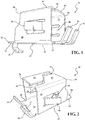
Figure 1 is a side perspective view of a compression spring retainer in accordance with a first embodiment; -
Figure 2 is a top perspective view of another compression spring retainer in accordance with the first embodiment; -
Figure 3 is an environmental side perspective view of a further compression spring retainer in accordance with the first embodiment, shown prior to a handle being disposed thereabout; -
Figure 4 is an environmental end view of another compression spring retainer in accordance with the first embodiment, shown disposed within an aperture defined by a handle; -
Figure 5 is an environmental side cut-away view of a compression spring retainer in accordance with the first embodiment, shown in an assembled configuration with a handle lacking a ferrule; -
Figure 6 is a top perspective view of a compression spring retainer in accordance with a second embodiment; -
Figure 7 is another top perspective view of the compression spring retainer shown inFigure 6 ; and -
Figure 8 is a perspective view of another compression spring retainer, shown prior to being disposed about a nut secured to a surface. - A compression spring retainer, and methods of securing an element to a surface with the same, is provided. As described in additional detail below, the compression spring retainer includes structure for increasing tightening torque via spring force during the tightening of a bolt during the securement (i.e., installation) of an element to a surface of a body, structure for reducing rotational gap during such installation of the element, and structure for protecting the body from deformation during securement of the element to the surface thereof. These structures, and thus the compression spring retainer and related methods, provide increased ease of securement of elements to surfaces and decreased potential and magnitude of slop/play between an element and a surface due to a connecting bolt loosening over time.
- Referring to
Figures 1-5 , wherein like numerals indicate corresponding parts throughout the several views, a first embodiment of a compression spring retainer is illustrated and generally designated at 10. Certain features of thecompression spring retainer 10 are functional, but can be implemented in different aesthetic configurations. Thecompression spring retainer 10 includes abody 12, aresilient compression leg 14, and a resilientanti-deformation leg 16. - In general, the
body 12 is adapted to be disposed about (i.e., at least partially fit over) anut 18, which is typically secured (or securable) to asurface 20. The shape of thenut 18 is not limited, and can include a variety of cross sectional and/or perimeter shapes, such as square, hexagonal, circular, and polygonal shapes. Thenut 18 typically defines an interior adapted (e.g. threaded) to receive a fastener 58 (e.g. a bolt 58), as discussed in further detail below. In some instances, thesurface 20 is an exterior (e.g. outward-facing side) of an item of hollowware or cookware, such as a frying pan. However, thesurface 20 not limited, and may be a surface not associated with cookware. - The
body 12 includes afirst end 22, asecond end 26, and abase portion 24 extending lengthwise therebetween. Thebody 12 also includes afirst side portion 28 and asecond side portion 30. More specifically, thefirst side portion 28 extends upwardly from thebase portion 24 at afirst edge 32, which extends between thefirst end 22 and thesecond end 26. Similarly, thesecond side portion 30 extends upwardly from thebase portion 24 at asecond edge 34, which extends between thefirst end 22 and thesecond end 26 opposite thefirst edge 32. The first andsecond side portions base portion 24, or may extend at an acute or obtuse angle thereto. Thefirst side portion 28 includes a firsttop edge 36, and thesecond side portion 30 includes a secondtop edge 38. - The
body 12 also includes a firsthorizontal member 40, which extends inwardly from the firsttop edge 36 of thefirst side portion 28 toward the secondtop edge 38 of thesecond side portion 30. Thebody 12 further includes a secondhorizontal member 42, which extends inwardly from the secondtop edge 38 of thesecond side portion 30 toward the firsttop edge 36 of thefirst side portion 28. Typically, the firsthorizontal member 40 and the secondhorizontal member 42 each independently define a planar surface opposing and generally parallel to (i.e. overlapping with) thebase portion 24. The firsthorizontal member 40 and the secondhorizontal member 42 may also overlap one another (not shown). Alternatively, the firsthorizontal member 40 and the secondhorizontal member 42 may not overlap one another, but instead cooperatively define agap 44 therebetween. Thegap 44 may be any shape, and may extend linearly or non-linearly between the first andsecond ends 22, 26 (i.e., lengthwise across) of thebody 12. For example, thegap 44 may zig-zag along the length of thebody 12, may extend along a curvilinear path, or may conform to a line that is parallel to the firsttop edge 36 and/or the secondtop edge 38, or angled with respect to one of the first and secondtop edges - The
resilient compression leg 14 is joined to thefirst end 22 of thebody 12. More specifically, theresilient compression leg 14 extends outwardly from thefirst end 22, and typically includes at least a portion that extends above the plane generally defined by thebase portion 24 of thebody 12. Theresilient compression leg 14 may be joined to and extend outwardly and upwardly from thebase portion 24 at thefirst end 22 of thebody 12. The angle at which theresilient compression leg 14 extends upwardly from thebase portion 24 is not limited, and includes angles, as measured with respect to the plane generally defined by thebase portion 24, falling within the range of from 10 to 80 degrees, such as from 10 to 70, from 20 to 70 degrees, from 20 to 60, from and from 30 to 60 degrees. Theresilient compression leg 12 can be integrally joined to the body 12 (e.g. to thebase portion 24 thereof). Optionally, thecompression spring retainer 10 includes tworesilient compression legs 14, i.e., a firstresilient compression leg 14 and a secondresilient compression leg 14, which are each as generally described with respect to thecompression leg 14 above. - The resilient
anti-deformation leg 16 is joined to thesecond end 26 of thebody 12. More specifically, the resilientanti-deformation leg 16 extends outwardly from thesecond end 26, and is configured to be shaped such that at least a portion of the resilientanti-deformation leg 16 extends below the plane generally defined by thebase portion 24 of thebody 12. The resilientanti-deformation leg 16 may be joined to and extend outwardly and downwardly from thebase portion 24 at thesecond end 26 of thebody 12. The resilientanti-deformation leg 16 can be integrally joined to the body 12 (e.g. to thebase portion 24 thereof). Generally, the resilientanti-deformation leg 16 when viewed from a side defines a shape having no sharp edges or corners pointing generally away from thebody 12 in a direction parallel to an axis of thebase portion 24 running from thefirst end 22 toward thesecond end 26. Such sharp edges or corners might otherwise contact thesurface 20 to which thenut 18 is secured when thecompression spring retainer 10 is installed, as described below, which reduces deformation forces applied to thesurface 20, e.g. from thecompression spring retainer 10. Typically, the resilientanti-deformation leg 16 includes a curved portion that when viewed from a side optionally generally conforms in part to the contour of a half-circle or, further optionally, to the contour of a "U" (i.e., the resilientanti-deformation leg 16 may have a generally or substantially U-shaped side-profile). Optionally, the resilientanti-deformation leg 16 includes a free terminal end that, when thecompression spring retainer 10 is in an installed configuration as described below, has an edge that is biased in a direction pointing away from thesurface 20 to which thenut 18 is secured. The shape of the free terminal end of theanti-deformation leg 16 when viewed from a side can optionally define a shape generally discontinuous with the shape of a non-terminal portion of the resilientanti-deformation leg 16 viewed from a corresponding side, e.g. such that the free terminal end of the resilientanti-deformation leg 16 may generally bend upward or downward, or have a curved shape not fully conforming to the general shape to which a non-terminal portion of the resilientanti-deformation leg 16 conforms when viewed from a side. - As best shown in
Figure 5 , thecompression spring retainer 10 may include abur 46 that extends from at least one of thefirst side portion 28, thesecond side portion 30, the firsthorizontal member 40, the secondhorizontal member 42, and thebase portion 24. Thebur 46 is a generally pointed projection that extends from a surface of thecompression spring retainer 10, e.g. located on thefirst side portion 28, thesecond side portion 30, the firsthorizontal member 40, the secondhorizontal member 42, or thebase portion 24. It is to be understood that the functionality, as described below, of thebur 46 can be alternatively achieved by a protrusion or a plurality of protrusions of various independently selected shapes and configurations, which may each extend from thecompression spring retainer 10 as described above. - The
compression spring retainer 10 may include aretention member 48. Theretention member 48 typically extends outwardly from the first orsecond side portions retention member 48 extends outwardly and toward thesecond end 26 of thebody 12. However, theretention member 48 may extend in any direction with respect to the body 12.Theretention member 48 is resilient, and adapted to provide outward compressive force, as described in further detail below. Theretention member 48 may be integrally joined with thebody 12, e.g. at the first orsecond side portions compression spring retainer 10 includes tworetention members 48, i.e., afirst retention member 48 and asecond retention member 48, which are each as generally described above with respect to theretention member 48. Thecompression spring retainer 10 may includeadditional retention members 48 as well. In such instances where thecompression spring retainer 10 includes more than oneretention member 48, eachretention member 48 typically extends outwardly from a different portion of thebody 12, such as from any one of thefirst side portion 28, thesecond side portion 30, the firsthorizontal member 40, and the secondhorizontal member 42. - With particular reference to
Figures 3-5 , the features and elements of thecompression spring retainer 10 described herein cooperatively engage various portions of thenut 18 and anelement 52 during the securement of theelement 52 to thesurface 20 on which thenut 18 is secured. Accordingly, the method of securing theelement 52 to thesurface 20 with thecompression spring retainer 10 is described below. - The method includes disposing the
compression spring retainer 10 about thenut 18 secured to thesurface 20. As described above, thesurface 20 is not limited, and may be the surface of any article. In some instances, thesurface 20 is a side of an item of cookware, such as a base of a pot or pan (e.g. a frying pan). Thecompression spring retainer 10 may be disposed about thenut 18 in any fashion. Typically, disposing thecompression spring retainer 10 about thenut 18 includes generally placing (e.g. inserting) thenut 18 at least partially within an internal volume delimited by thebody 12, and contacting thesurface 20 with the resilientanti-deformation leg 16 of thecompression spring retainer 10. Disposing thecompression spring retainer 10 about thenut 18 typically also includes contacting at least three sides of the nut 18 (or less if thenut 18 is not polygonal in outer shape) with the compression spring retainer 10 (e.g. with thebase portion 24, the first and/orsecond side portions horizontal members 40, 42). Thecompression spring retainer 10 so disposed about thenut 18 may be referred to as an installed configuration. In certain implementations, the at least onebur 46 will bite into a surface of thenut 18 in the installed configuration, and thereby impose a force resisting removal of thecompression spring retainer 10 from the nut 18 (e.g. prevent removing thecompression spring retainer 10 from the installed configuration). - As best shown in
Figures 4 and5 , the method also includes disposing thecompression spring retainer 10 and the nut 18 (i.e., in the installed configuration) into anaperture 50 defined by theelement 52. Theelement 52 may include a decorative element 54 (e.g. ferrule 54, or other such embellishment) corresponding to an end of theelement 52 intended to be most proximal to thesurface 20 when theelement 52 is secured thereto. The decorative element 54can optionally cooperate with theelement 52 to establish proper securement of theelement 52 to thesurface 20, e.g. via cooperation with thecompression spring retainer 10. Typically, disposing thecompression spring retainer 10 and thenut 18 into theaperture 50 includes contacting opposing lateral side surfaces of theaperture 50 with thecompression spring retainer 10. More specifically, theretention members 48 are typically compressed against the opposing lateral side surfaces of theaperture 50, and cooperatively function as a spring imposing a force on the lateral sides, and further biting into the lateral sides, in such a manner as to effectively resist withdrawal of thecompression spring retainer 10, and thus thenut 18, from theaperture 50 of theelement 52. Disposing thecompression spring retainer 10 and thenut 18 into theaperture 50 also typically includes contacting aback surface 56 of theaperture 50 with theresilient compression leg 14 of thecompression spring retainer 10. So positioned, anopening 60 defined in theelement 52, which extends through theback surface 56 thereof, is aligned with the interior of thenut 18. Accordingly, the method also includes disposing afastener 58 through theopening 60 and securably engaging thefastener 58 with thenut 18. In specific instances, as described above, thefastener 58 is a bolt 58 (e.g. an M4 screw) and the interior of thenut 18 is threaded, such that securably engaging thefastener 58 is further defined as threadably engaging thebolt 58 with the threaded interior of thenut 18. However, thefastener 58 andnut 18 may not be threadably engageable, but may instead be a push-type (or snap-type) fastener pairing without departing from the scope of this disclosure. - In general, securably engaging the
fastener 58 with thenut 18 causes a biasing force to be formed between the resilientanti-deformation leg 16 and theresilient compression leg 14 in a lengthwise direction of thebody 12. This biasing force functions to increase torque during and subsequent to engaging thefastener 58 with thenut 18 so as to reduce any tendency of thefastener 58 to loosen from engagement with thenut 18. The biasing force further functions to prevent slop/play between theelement 52 and thesurface 20. Additionally, securably engaging thefastener 58 with thenut 18 causes the retention member(s) 48 function to reduce the rotational gap between thecompression spring retainer 10 and theaperture 50, thereby properly aligning theelement 52 during securement thereof to thesurface 20. By reducing the rotational gap, the retention member(s) 48 also function to resist rotation or slop/play of theelement 52 subsequent to thefastener 58 being securably engaged with thenut 18. The resilientanti-deformation leg 16 functions during to prevent deformation of thesurface 20 securement of theelement 52 thereto, by cooperating with theresilient compression leg 14 to act as a spring force between thesurface 20 and theelement 52 and thereby preventing over-tightening of thefastener 58. In other words, thecompression spring retainer 10 contacts and imposes forces upon thesurface 20 during and subsequent to securement of theelement 52 thereto, and the resilientanti-deformation leg 16 functions to ensure that such forces do not cause undesirable deformations of thesurface 20. - Referring to
Figures 6-8 , wherein like numerals indicate corresponding parts throughout the several views, a second embodiment of the compression spring retainer is illustrated and generally designated at 62. Certain features of thecompression spring retainer 62 are functional, but can be implemented in different aesthetic configurations. Thecompression spring retainer 62 is identical to thecompression spring retainer 10 according to the first embodiment, with the exception that thecompression spring retainer 62 does not include either of the first and secondhorizontal members barb 64. - More specifically, the
compression spring retainer 62 includes thebarb 64, which extends inwardly from at least one of the first andsecond side portions compression spring retainer 62 includesmultiple barbs 64 extending from both of the first andsecond side portions Figures 6-8 .Such barbs 64 are independently configured and shaped, and each function to bite into a surface of thenut 18 in the installed configuration, and thereby impose a force resisting removal of thecompression spring retainer 62 from the nut 18 (e.g. prevent removing thecompression spring retainer 62 from the installed configuration). Thecompression spring container 62 may include an additional or alternative protrusion, bur, or other alternative element, or a combination thereof, to achieve the same function as that described herein for thebarb 64, including variations on thebur 46. - The method of securing the
element 52 to thesurface 20 described above with regard to thecompression spring retainer 10 according to the first embodiment may equally be performed using thecompression spring retainer 62 according to the second embodiment. However, as thecompression spring retainer 62 does not include the first and secondhorizontal members body 12 does not overlie a top surface of thenut 18 subsequent to being positioned thereon (as does thebody 12 of the compression spring retainer 10). Therefore, as best shown inFigure 8 , disposing thecompression spring retainer 62 about thenut 18 typically includes pressing thecompression spring retainer 62 laterally about the nut 18 (e.g. from a side position thereto). For example, disposing thecompression spring retainer 62 about thenut 18 may include moving thecompression spring retainer 62 in an upward direction 66 from beneath thenut 18 to place thenut 18 at least partially within the internal volume delimited by the body 12 (e.g. between the firsthorizontal member 40, the secondhorizontal member 42, and the base portion 24), while contacting thesurface 20 with the resilientanti-deformation leg 16. In this fashion, disposing thecompression spring retainer 62 about thenut 18 also includes contacting a surface of thenut 18 with the barb(s) 64, which as described above, serves to prevent subsequent removal of thecompression spring retainer 62 from thenut 18. - The various elements of the components of the embodiments of the
compression spring retainer body 12, theresilient compression leg 14, theretention member 48, the resilientanti-deformation leg 16, thebur 46, and thebarb 64, may be manufactured of the same or different material(s), such as any one or more of the materials described below. Typically, thecompression spring retainer compression spring retainer compression spring retainer body 12, theresilient compression leg 14, theretention member 48, the resilientanti-deformation leg 16, thebur 46, and/or the barb 64), include metals (e.g. steels, aluminums, alloys, etc.), resins (e.g. thermoset and/or thermoplastic resins), and combinations thereof. However, myriad materials may be used to manufacture the elements of thecompression spring retainer - In some embodiments, the
compression spring retainer - In some embodiments, the resin is selected from thermoset resins and thermoplastic resins. Examples of suitable thermoset and/or thermoplastic resins typically include polyamides (PA), such as Nylons; polyesters such as polyethylene terephthalates (PET), polybutylene terephthalates (PET), polytrimethylene terephthalates (PTT), polyethylene naphthalates (PEN), liquid crystalline polyesters, and the like; polyolefins such as polyethylenes (PE), polypropylenes (PP), polybutylenes, and the like; styrenic resins; polyoxymethylenes (POM); polycarbonates (PC); polymethylenemethacrylates (PMMA); polyvinyl chlorides (PVC); polyphenylene sulfides (PPS); polyphenylene ethers (PPE); polyimides (PI); polyamideimides (PAI); polyetherimides (PEI); polysulfones (PSU); polyethersulfones; polyketones (PK); polyetherketones (PEK); polyetheretherketones (PEEK); polyetherketoneketones (PEKK); polyarylates (PAR); polyethernitriles (PEN); resol-type; urea (e.g. melamine-type); phenoxy resins; fluorinated resins, such as polytetrafluoroethylenes; thermoplastic elastomers, such as polystyrene types, polyolefin types, polyurethane types, polyester types, polyamide types, polybutadiene types, polyisoprene types, fluoro types, and the like; and copolymers, modifications, and combinations thereof.
- The above description relates to general and specific embodiments of the disclosure. However, various alterations and changes can be made without departing from the spirit and broader aspects of the disclosure as defined in the appended claims, which are to be interpreted in accordance with the principles of patent law including the doctrine of equivalents. As such, this disclosure is presented for illustrative purposes and should not be interpreted as an exhaustive description of all embodiments of the disclosure or to limit the scope of the claims to the specific elements illustrated or described in connection with these embodiments. Any reference to elements in the singular, for example, using the articles "a," "an," "the," or "said," is not to be construed as limiting the element to the singular. Further, terms such as "orthogonal", "horizontal," and "vertical" are not to be interpreted in an absolute sense subject to the rigorous demands of geometric precision but, rather, as general indicators of a configurational arrangement between two or more elements. For example, the word "orthogonal" as used herein is not exclusive of the possibility wherein two surfaces being "orthogonal" to one another form an angle having a value other than 90 degrees at a point of intersection. The term "resilient" as used herein is readily understood in the art, and is to be interpreted accordingly. In particular, the term resilient is used herein to refer to an ability to recoil or spring back to an original position in response to an applied force. However, when limited by an intervening element (e.g. the
aperture 50, thesurface 20, etc.), the resilient elements of thecompression spring retainer - Likewise, it is also to be understood that the appended claims are not limited to express and particular compounds, compositions, or methods described in the detailed description, which may vary between particular embodiments that fall within the scope of the appended claims. With respect to any Markush groups relied upon herein for describing particular features or aspects of various embodiments, different, special, and/or unexpected results may be obtained from each member of the respective Markush group independent from all other Markush members. Each member of a Markush group may be relied upon individually and or in combination and provides adequate support for specific embodiments within the scope of the appended claims.
Claims (15)
- A compression spring retainer comprising:a body adapted to be disposed about a nut and including a base portion extending between a first end and a second end of the body, a first side portion extending upwardly from the base portion between the first and second ends, and a second side portion extending upwardly from the base portion between the first and second ends opposite the first side portion;a resilient compression leg extending outwardly from the first end of the body, the resilient compression leg being configured to provide a biasing force in a lengthwise direction of the body; anda resilient anti-deformation leg extending outwardly from the second end of the body, where at least a portion of the resilient anti-deformation leg extends below a plane defined by the base portion of the body.
- The compression spring retainer of claim 1, wherein the resilient compression leg is further defined as a first resilient compression leg, and the compression spring retainer further comprises a second resilient compression leg joined to the first end of the body.
- The compression spring retainer of claim 2, wherein the first and second resilient compression legs extend upwardly from the base portion of the body.
- The compression spring retainer of any one of claims 1-3, wherein the resilient anti-deformation leg includes a curved portion.
- The compression spring retainer of any one of claims 1-4, wherein the first side portion and the second side portion are orthogonal to the base portion.
- The compression spring retainer of any one of claims 1-5, further comprising a barb extending from at least one of the first side portion and the second side portion.
- The compression spring retainer of any one of claims 1-6, further comprising:a first horizontal member extending inwardly from a top edge of the first side portion; anda second horizontal member extending inwardly from a top edge of the second side portion toward the first horizontal member;wherein each of the first and second horizontal members defines a planar surface opposing and generally parallel to the base portion.
- The compression spring retainer of claim 7, wherein the first and second horizontal members do not overlap one another.
- The compression spring retainer of claim 7 or 8, wherein the first horizontal member and the second horizontal member cooperatively define a non-linear gap therebetween.
- The compression spring retainer of any one of claims 7-9, further comprising a burr extending from at least one of the first side portion, the second side portion, the first horizontal member, the second horizontal member, and the base portion.
- The compression spring retainer of any one of claims 1-10, further comprising a first retention member extending outwardly from the first side portion of the body and a second retention member extending outwardly from the second side portion of the body.
- The compression spring retainer of any one of claims 1-11, wherein the resilient compression leg and the resilient anti-deformation leg are each integrally joined to the body.
- A method of securing an element to a surface, comprising:disposing a compression spring retainer about a nut secured to the surface, thereby contacting at least three sides of the nut with the compression spring retainer;disposing the compression spring retainer and the nut into an aperture defined by the element, thereby contacting opposing lateral side surfaces and a back surface of the aperture with the compression spring retainer;disposing a bolt through an opening defined in the element, wherein the opening passes through the back surface of the aperture and is in alignment with a threaded interior of the nut; andthreadably engaging the bolt with the threaded interior of the nut, thereby securing the element to the surface;wherein the compression spring retainer is the compression spring retainer of any one of claims 1-12.
- The method of claim 13, wherein disposing the compression spring retainer about the nut further includes contacting the surface with the resilient anti-deformation leg of the compression spring retainer, and wherein disposing the compression spring retainer and the nut into the aperture further includes contacting the back surface of the aperture with the resilient compression leg of the compression spring retainer.
- The method of claim 13 or 14, wherein the element is a handle and the surface is a side of an item of cookware.
Priority Applications (1)
| Application Number | Priority Date | Filing Date | Title |
|---|---|---|---|
| EP18382415.0A EP3581081B1 (en) | 2018-06-12 | 2018-06-12 | Compression spring retainer and method of use thereof |
Applications Claiming Priority (1)
| Application Number | Priority Date | Filing Date | Title |
|---|---|---|---|
| EP18382415.0A EP3581081B1 (en) | 2018-06-12 | 2018-06-12 | Compression spring retainer and method of use thereof |
Publications (2)
| Publication Number | Publication Date |
|---|---|
| EP3581081A1 true EP3581081A1 (en) | 2019-12-18 |
| EP3581081B1 EP3581081B1 (en) | 2021-07-28 |
Family
ID=62716019
Family Applications (1)
| Application Number | Title | Priority Date | Filing Date |
|---|---|---|---|
| EP18382415.0A Active EP3581081B1 (en) | 2018-06-12 | 2018-06-12 | Compression spring retainer and method of use thereof |
Country Status (1)
| Country | Link |
|---|---|
| EP (1) | EP3581081B1 (en) |
Citations (4)
| Publication number | Priority date | Publication date | Assignee | Title |
|---|---|---|---|---|
| DE6811101U (en) * | 1968-12-12 | 1969-05-14 | Dingerkus Geb | COOKING AND / OR FRYING POT WITH AT LEAST ONE DETACHABLE HANDLE |
| US4032032A (en) * | 1976-05-04 | 1977-06-28 | William Michael Carroll | Flame guard anti-rotation device |
| US20050117993A1 (en) * | 2000-11-20 | 2005-06-02 | Eustathios Vassiliou | Combination fastener |
| EP2837315A1 (en) * | 2013-08-15 | 2015-02-18 | AMT Alumetall Gießtechnik GmbH | Cooking dishes |
-
2018
- 2018-06-12 EP EP18382415.0A patent/EP3581081B1/en active Active
Patent Citations (4)
| Publication number | Priority date | Publication date | Assignee | Title |
|---|---|---|---|---|
| DE6811101U (en) * | 1968-12-12 | 1969-05-14 | Dingerkus Geb | COOKING AND / OR FRYING POT WITH AT LEAST ONE DETACHABLE HANDLE |
| US4032032A (en) * | 1976-05-04 | 1977-06-28 | William Michael Carroll | Flame guard anti-rotation device |
| US20050117993A1 (en) * | 2000-11-20 | 2005-06-02 | Eustathios Vassiliou | Combination fastener |
| EP2837315A1 (en) * | 2013-08-15 | 2015-02-18 | AMT Alumetall Gießtechnik GmbH | Cooking dishes |
Also Published As
| Publication number | Publication date |
|---|---|
| EP3581081B1 (en) | 2021-07-28 |
Similar Documents
| Publication | Publication Date | Title |
|---|---|---|
| CN101855462B (en) | Panel fastener | |
| US11746811B2 (en) | Connector pin | |
| JP7427424B2 (en) | Fastener feedback mechanism | |
| US7896601B2 (en) | Two-piece Fastener | |
| KR102719273B1 (en) | Compliant hanger assembly | |
| US10808745B1 (en) | Releasable slot fastener | |
| EP2241766A1 (en) | Band clamp | |
| US5280866A (en) | Fastener for elongated bodies | |
| US11781585B2 (en) | Channel fastener having tapering support body | |
| US11577666B2 (en) | Arrowhead fastener clip with barbs | |
| EP2175148A2 (en) | Nut retainer | |
| EP3730808B1 (en) | Fastener clip with push nut | |
| WO2018061005A1 (en) | Fastener systems with overtightening and loosening prevention | |
| KR20100122856A (en) | Fastener | |
| JP5377196B2 (en) | securing bracket | |
| CN111987657B (en) | Releasable cable tie fastener | |
| JP5234908B2 (en) | Floor panel support structure | |
| EP3581081B1 (en) | Compression spring retainer and method of use thereof | |
| US20170082133A1 (en) | Detachable sleeve and fastener assembly including the detachable sleeve | |
| KR20170084247A (en) | Stay tight threaded fasteners | |
| US11767872B2 (en) | Panel fastener assembly | |
| US20130064623A1 (en) | Fastening unit | |
| US20190323537A1 (en) | Bayonet fastener assembly | |
| US8177467B2 (en) | Fastening device having fastening element | |
| CN112696419A (en) | Sheet metal nut that unilateral reached |
Legal Events
| Date | Code | Title | Description |
|---|---|---|---|
| PUAI | Public reference made under article 153(3) epc to a published international application that has entered the european phase |
Free format text: ORIGINAL CODE: 0009012 |
|
| STAA | Information on the status of an ep patent application or granted ep patent |
Free format text: STATUS: THE APPLICATION HAS BEEN PUBLISHED |
|
| AK | Designated contracting states |
Kind code of ref document: A1 Designated state(s): AL AT BE BG CH CY CZ DE DK EE ES FI FR GB GR HR HU IE IS IT LI LT LU LV MC MK MT NL NO PL PT RO RS SE SI SK SM TR |
|
| AX | Request for extension of the european patent |
Extension state: BA ME |
|
| STAA | Information on the status of an ep patent application or granted ep patent |
Free format text: STATUS: REQUEST FOR EXAMINATION WAS MADE |
|
| 17P | Request for examination filed |
Effective date: 20200618 |
|
| RBV | Designated contracting states (corrected) |
Designated state(s): AL AT BE BG CH CY CZ DE DK EE ES FI FR GB GR HR HU IE IS IT LI LT LU LV MC MK MT NL NO PL PT RO RS SE SI SK SM TR |
|
| STAA | Information on the status of an ep patent application or granted ep patent |
Free format text: STATUS: EXAMINATION IS IN PROGRESS |
|
| 17Q | First examination report despatched |
Effective date: 20201009 |
|
| GRAP | Despatch of communication of intention to grant a patent |
Free format text: ORIGINAL CODE: EPIDOSNIGR1 |
|
| STAA | Information on the status of an ep patent application or granted ep patent |
Free format text: STATUS: GRANT OF PATENT IS INTENDED |
|
| INTG | Intention to grant announced |
Effective date: 20210209 |
|
| GRAS | Grant fee paid |
Free format text: ORIGINAL CODE: EPIDOSNIGR3 |
|
| GRAA | (expected) grant |
Free format text: ORIGINAL CODE: 0009210 |
|
| STAA | Information on the status of an ep patent application or granted ep patent |
Free format text: STATUS: THE PATENT HAS BEEN GRANTED |
|
| AK | Designated contracting states |
Kind code of ref document: B1 Designated state(s): AL AT BE BG CH CY CZ DE DK EE ES FI FR GB GR HR HU IE IS IT LI LT LU LV MC MK MT NL NO PL PT RO RS SE SI SK SM TR |
|
| REG | Reference to a national code |
Ref country code: GB Ref legal event code: FG4D |
|
| REG | Reference to a national code |
Ref country code: CH Ref legal event code: EP |
|
| REG | Reference to a national code |
Ref country code: DE Ref legal event code: R096 Ref document number: 602018020760 Country of ref document: DE |
|
| REG | Reference to a national code |
Ref country code: AT Ref legal event code: REF Ref document number: 1413936 Country of ref document: AT Kind code of ref document: T Effective date: 20210815 |
|
| REG | Reference to a national code |
Ref country code: IE Ref legal event code: FG4D |
|
| REG | Reference to a national code |
Ref country code: LT Ref legal event code: MG9D |
|
| REG | Reference to a national code |
Ref country code: NL Ref legal event code: MP Effective date: 20210728 |
|
| REG | Reference to a national code |
Ref country code: AT Ref legal event code: MK05 Ref document number: 1413936 Country of ref document: AT Kind code of ref document: T Effective date: 20210728 |
|
| PG25 | Lapsed in a contracting state [announced via postgrant information from national office to epo] |
Ref country code: SE Free format text: LAPSE BECAUSE OF FAILURE TO SUBMIT A TRANSLATION OF THE DESCRIPTION OR TO PAY THE FEE WITHIN THE PRESCRIBED TIME-LIMIT Effective date: 20210728 Ref country code: RS Free format text: LAPSE BECAUSE OF FAILURE TO SUBMIT A TRANSLATION OF THE DESCRIPTION OR TO PAY THE FEE WITHIN THE PRESCRIBED TIME-LIMIT Effective date: 20210728 Ref country code: HR Free format text: LAPSE BECAUSE OF FAILURE TO SUBMIT A TRANSLATION OF THE DESCRIPTION OR TO PAY THE FEE WITHIN THE PRESCRIBED TIME-LIMIT Effective date: 20210728 Ref country code: ES Free format text: LAPSE BECAUSE OF FAILURE TO SUBMIT A TRANSLATION OF THE DESCRIPTION OR TO PAY THE FEE WITHIN THE PRESCRIBED TIME-LIMIT Effective date: 20210728 Ref country code: FI Free format text: LAPSE BECAUSE OF FAILURE TO SUBMIT A TRANSLATION OF THE DESCRIPTION OR TO PAY THE FEE WITHIN THE PRESCRIBED TIME-LIMIT Effective date: 20210728 Ref country code: NO Free format text: LAPSE BECAUSE OF FAILURE TO SUBMIT A TRANSLATION OF THE DESCRIPTION OR TO PAY THE FEE WITHIN THE PRESCRIBED TIME-LIMIT Effective date: 20211028 Ref country code: PT Free format text: LAPSE BECAUSE OF FAILURE TO SUBMIT A TRANSLATION OF THE DESCRIPTION OR TO PAY THE FEE WITHIN THE PRESCRIBED TIME-LIMIT Effective date: 20211129 Ref country code: NL Free format text: LAPSE BECAUSE OF FAILURE TO SUBMIT A TRANSLATION OF THE DESCRIPTION OR TO PAY THE FEE WITHIN THE PRESCRIBED TIME-LIMIT Effective date: 20210728 Ref country code: BG Free format text: LAPSE BECAUSE OF FAILURE TO SUBMIT A TRANSLATION OF THE DESCRIPTION OR TO PAY THE FEE WITHIN THE PRESCRIBED TIME-LIMIT Effective date: 20211028 Ref country code: AT Free format text: LAPSE BECAUSE OF FAILURE TO SUBMIT A TRANSLATION OF THE DESCRIPTION OR TO PAY THE FEE WITHIN THE PRESCRIBED TIME-LIMIT Effective date: 20210728 Ref country code: LT Free format text: LAPSE BECAUSE OF FAILURE TO SUBMIT A TRANSLATION OF THE DESCRIPTION OR TO PAY THE FEE WITHIN THE PRESCRIBED TIME-LIMIT Effective date: 20210728 |
|
| PG25 | Lapsed in a contracting state [announced via postgrant information from national office to epo] |
Ref country code: PL Free format text: LAPSE BECAUSE OF FAILURE TO SUBMIT A TRANSLATION OF THE DESCRIPTION OR TO PAY THE FEE WITHIN THE PRESCRIBED TIME-LIMIT Effective date: 20210728 Ref country code: LV Free format text: LAPSE BECAUSE OF FAILURE TO SUBMIT A TRANSLATION OF THE DESCRIPTION OR TO PAY THE FEE WITHIN THE PRESCRIBED TIME-LIMIT Effective date: 20210728 Ref country code: GR Free format text: LAPSE BECAUSE OF FAILURE TO SUBMIT A TRANSLATION OF THE DESCRIPTION OR TO PAY THE FEE WITHIN THE PRESCRIBED TIME-LIMIT Effective date: 20211029 |
|
| PG25 | Lapsed in a contracting state [announced via postgrant information from national office to epo] |
Ref country code: DK Free format text: LAPSE BECAUSE OF FAILURE TO SUBMIT A TRANSLATION OF THE DESCRIPTION OR TO PAY THE FEE WITHIN THE PRESCRIBED TIME-LIMIT Effective date: 20210728 |
|
| REG | Reference to a national code |
Ref country code: DE Ref legal event code: R097 Ref document number: 602018020760 Country of ref document: DE |
|
| PG25 | Lapsed in a contracting state [announced via postgrant information from national office to epo] |
Ref country code: SM Free format text: LAPSE BECAUSE OF FAILURE TO SUBMIT A TRANSLATION OF THE DESCRIPTION OR TO PAY THE FEE WITHIN THE PRESCRIBED TIME-LIMIT Effective date: 20210728 Ref country code: SK Free format text: LAPSE BECAUSE OF FAILURE TO SUBMIT A TRANSLATION OF THE DESCRIPTION OR TO PAY THE FEE WITHIN THE PRESCRIBED TIME-LIMIT Effective date: 20210728 Ref country code: RO Free format text: LAPSE BECAUSE OF FAILURE TO SUBMIT A TRANSLATION OF THE DESCRIPTION OR TO PAY THE FEE WITHIN THE PRESCRIBED TIME-LIMIT Effective date: 20210728 Ref country code: EE Free format text: LAPSE BECAUSE OF FAILURE TO SUBMIT A TRANSLATION OF THE DESCRIPTION OR TO PAY THE FEE WITHIN THE PRESCRIBED TIME-LIMIT Effective date: 20210728 Ref country code: CZ Free format text: LAPSE BECAUSE OF FAILURE TO SUBMIT A TRANSLATION OF THE DESCRIPTION OR TO PAY THE FEE WITHIN THE PRESCRIBED TIME-LIMIT Effective date: 20210728 Ref country code: AL Free format text: LAPSE BECAUSE OF FAILURE TO SUBMIT A TRANSLATION OF THE DESCRIPTION OR TO PAY THE FEE WITHIN THE PRESCRIBED TIME-LIMIT Effective date: 20210728 |
|
| PLBE | No opposition filed within time limit |
Free format text: ORIGINAL CODE: 0009261 |
|
| STAA | Information on the status of an ep patent application or granted ep patent |
Free format text: STATUS: NO OPPOSITION FILED WITHIN TIME LIMIT |
|
| 26N | No opposition filed |
Effective date: 20220429 |
|
| PG25 | Lapsed in a contracting state [announced via postgrant information from national office to epo] |
Ref country code: IT Free format text: LAPSE BECAUSE OF FAILURE TO SUBMIT A TRANSLATION OF THE DESCRIPTION OR TO PAY THE FEE WITHIN THE PRESCRIBED TIME-LIMIT Effective date: 20210728 |
|
| REG | Reference to a national code |
Ref country code: DE Ref legal event code: R119 Ref document number: 602018020760 Country of ref document: DE |
|
| PG25 | Lapsed in a contracting state [announced via postgrant information from national office to epo] |
Ref country code: MC Free format text: LAPSE BECAUSE OF FAILURE TO SUBMIT A TRANSLATION OF THE DESCRIPTION OR TO PAY THE FEE WITHIN THE PRESCRIBED TIME-LIMIT Effective date: 20210728 |
|
| REG | Reference to a national code |
Ref country code: CH Ref legal event code: PL |
|
| REG | Reference to a national code |
Ref country code: BE Ref legal event code: MM Effective date: 20220630 |
|
| GBPC | Gb: european patent ceased through non-payment of renewal fee |
Effective date: 20220612 |
|
| PG25 | Lapsed in a contracting state [announced via postgrant information from national office to epo] |
Ref country code: LU Free format text: LAPSE BECAUSE OF NON-PAYMENT OF DUE FEES Effective date: 20220612 Ref country code: LI Free format text: LAPSE BECAUSE OF NON-PAYMENT OF DUE FEES Effective date: 20220630 Ref country code: IE Free format text: LAPSE BECAUSE OF NON-PAYMENT OF DUE FEES Effective date: 20220612 Ref country code: CH Free format text: LAPSE BECAUSE OF NON-PAYMENT OF DUE FEES Effective date: 20220630 |
|
| PG25 | Lapsed in a contracting state [announced via postgrant information from national office to epo] |
Ref country code: GB Free format text: LAPSE BECAUSE OF NON-PAYMENT OF DUE FEES Effective date: 20220612 Ref country code: DE Free format text: LAPSE BECAUSE OF NON-PAYMENT OF DUE FEES Effective date: 20230103 Ref country code: BE Free format text: LAPSE BECAUSE OF NON-PAYMENT OF DUE FEES Effective date: 20220630 |
|
| P01 | Opt-out of the competence of the unified patent court (upc) registered |
Effective date: 20230526 |
|
| PG25 | Lapsed in a contracting state [announced via postgrant information from national office to epo] |
Ref country code: MK Free format text: LAPSE BECAUSE OF FAILURE TO SUBMIT A TRANSLATION OF THE DESCRIPTION OR TO PAY THE FEE WITHIN THE PRESCRIBED TIME-LIMIT Effective date: 20210728 Ref country code: CY Free format text: LAPSE BECAUSE OF FAILURE TO SUBMIT A TRANSLATION OF THE DESCRIPTION OR TO PAY THE FEE WITHIN THE PRESCRIBED TIME-LIMIT Effective date: 20210728 |
|
| PG25 | Lapsed in a contracting state [announced via postgrant information from national office to epo] |
Ref country code: HU Free format text: LAPSE BECAUSE OF FAILURE TO SUBMIT A TRANSLATION OF THE DESCRIPTION OR TO PAY THE FEE WITHIN THE PRESCRIBED TIME-LIMIT; INVALID AB INITIO Effective date: 20180612 |
|
| PG25 | Lapsed in a contracting state [announced via postgrant information from national office to epo] |
Ref country code: MT Free format text: LAPSE BECAUSE OF FAILURE TO SUBMIT A TRANSLATION OF THE DESCRIPTION OR TO PAY THE FEE WITHIN THE PRESCRIBED TIME-LIMIT Effective date: 20210728 |
|
| PGFP | Annual fee paid to national office [announced via postgrant information from national office to epo] |
Ref country code: FR Payment date: 20250625 Year of fee payment: 8 |
|
| PG25 | Lapsed in a contracting state [announced via postgrant information from national office to epo] |
Ref country code: TR Free format text: LAPSE BECAUSE OF FAILURE TO SUBMIT A TRANSLATION OF THE DESCRIPTION OR TO PAY THE FEE WITHIN THE PRESCRIBED TIME-LIMIT Effective date: 20210728 |