EP3581049B1 - Glove structure - Google Patents
Glove structure Download PDFInfo
- Publication number
- EP3581049B1 EP3581049B1 EP18739261.8A EP18739261A EP3581049B1 EP 3581049 B1 EP3581049 B1 EP 3581049B1 EP 18739261 A EP18739261 A EP 18739261A EP 3581049 B1 EP3581049 B1 EP 3581049B1
- Authority
- EP
- European Patent Office
- Prior art keywords
- piece
- glove
- finger
- palm
- injection molding
- Prior art date
- Legal status (The legal status is an assumption and is not a legal conclusion. Google has not performed a legal analysis and makes no representation as to the accuracy of the status listed.)
- Active
Links
Images



Classifications
-
- A—HUMAN NECESSITIES
- A41—WEARING APPAREL
- A41D—OUTERWEAR; PROTECTIVE GARMENTS; ACCESSORIES
- A41D19/00—Gloves
- A41D19/0055—Plastic or rubber gloves
- A41D19/0082—Details
-
- A—HUMAN NECESSITIES
- A41—WEARING APPAREL
- A41D—OUTERWEAR; PROTECTIVE GARMENTS; ACCESSORIES
- A41D19/00—Gloves
- A41D19/0006—Gloves made of several layers of material
-
- A—HUMAN NECESSITIES
- A41—WEARING APPAREL
- A41D—OUTERWEAR; PROTECTIVE GARMENTS; ACCESSORIES
- A41D19/00—Gloves
- A41D19/02—Arrangements for cutting-out, or shapes of, glove blanks
-
- A—HUMAN NECESSITIES
- A41—WEARING APPAREL
- A41D—OUTERWEAR; PROTECTIVE GARMENTS; ACCESSORIES
- A41D19/00—Gloves
- A41D19/0055—Plastic or rubber gloves
- A41D19/0058—Three-dimensional gloves
-
- A—HUMAN NECESSITIES
- A41—WEARING APPAREL
- A41D—OUTERWEAR; PROTECTIVE GARMENTS; ACCESSORIES
- A41D19/00—Gloves
- A41D19/0055—Plastic or rubber gloves
- A41D19/0058—Three-dimensional gloves
- A41D19/0065—Three-dimensional gloves with a textile layer underneath
-
- A—HUMAN NECESSITIES
- A41—WEARING APPAREL
- A41D—OUTERWEAR; PROTECTIVE GARMENTS; ACCESSORIES
- A41D19/00—Gloves
- A41D19/0055—Plastic or rubber gloves
- A41D19/0082—Details
- A41D19/0089—Joints between glove and cuff or garment
-
- A—HUMAN NECESSITIES
- A41—WEARING APPAREL
- A41D—OUTERWEAR; PROTECTIVE GARMENTS; ACCESSORIES
- A41D19/00—Gloves
- A41D19/015—Protective gloves
- A41D19/01576—Protective gloves made of a patchwork of different materials
-
- B—PERFORMING OPERATIONS; TRANSPORTING
- B29—WORKING OF PLASTICS; WORKING OF SUBSTANCES IN A PLASTIC STATE IN GENERAL
- B29D—PRODUCING PARTICULAR ARTICLES FROM PLASTICS OR FROM SUBSTANCES IN A PLASTIC STATE
- B29D99/00—Subject matter not provided for in other groups of this subclass
- B29D99/0064—Producing wearing apparel
- B29D99/0067—Gloves
Definitions
- the present disclosure relates to functional construction of a glove structure, and mainly to a glove structure which can maintain its required function in long term.
- glove cores of the general glove structures mostly have characteristics of flexibility, and the material is changed to plant from animal skin, then to modern synthetic leather and chemical fiber. Even, the glove cores are disposed with a plurality of different functional construction, and thus when the humans work for some potentially harmful activities, the glove structures can increase safety protection levels, or can achieve objectives of decoration or alarming.
- the implementation of the functional construction of the glove structure in usual is to dispose a piece with at least one function on the glove core.
- the material of the piece can be identical to or different from that of the glove core.
- the piece is bound to the glove core via a stitching manner or an adhesive manner.
- the glove core can have a palm portion and finger portions, the palm portion can have a palm piece, a palm side piece and a palm back piece, and each of the finger portions can have a finger piece, a finger side piece and a finger back piece.
- CN patent numbered CN 103415223B discloses a glove.
- paragraph [0036] of the CN patent discloses the non-injection molding assembly is adhered to the lining via an injection molding assembly to form a three-layer structure.
- this causes the injection molding assembly to need an area similar to that of the non-injection molding assembly for adhesion, and a weight and a thickness of the glove are thus increased due to the design of the three-layer structure. Further, such design further causes the overall hand operation to be not dexterous after wearing the glove.
- the region covered by the non-injection molding assembly is airtight, and this causes the user to feel that his/her hands are uncomfortable and muggy.
- the breathability of the non-injection molding assembly will be deceased or even lost if the design of the three-layer structure in the above CN patent is adopted for manufacturing the glove, i.e. the design of the three-layer structure in the above CN patent makes non-injection molding assembly lose its original function.
- an edge of the piece and the glove core form a section gap which is touched by an external force or object easily.
- a leak that easily leads to the large-area peeling of the piece is easily formed, and the design above three-layer structure causes the section gap to become larger.
- the larger section gap is touched by an external force or object more easily to make the piece separated from the glove core, the glove structure thus cannot maintain the required function in long term, and the usage lifetime of the glove structure is seriously affected.
- Patent application publication US 2014/0059739 A1 discloses a utility glove according to the preamble of claim 1. From patent application US 2009/0070916 A1 a personal protective garment is known that comprises a liner, an overlayer and at least one covering layer.
- the present disclosure provides a glove structure which can maintain its required function in long term, and further provides a glove using the glove structure.
- the glove structure of the present invention has the features of claim 1. Further embodiments are subject-matter of the dependent claims.
- the glove structure according to the invention at least comprises a glove core a piece, wherein a bottom surface of the piece covers an outer surface of the glove core, and the glove structure is characterized in, the outer surface is configured to have an injection molding assembly and the injection molding assembly fills a section of the piece.
- the glove structure of the present disclosure can have a shielding effect due to a section gap formed between the injection molding assembly and the piece and the glove core, and at the same time, it produces the fixing effect for bonding the piece, therefore providing positive and reliable means for preventing the edge of the piece from being separated from the glove core, making the glove structure maintain its required function in long term and increasing the quality of the glove structure. Further, by filling the section of the piece with the injection molding assembly, the original function of the piece will not be affected, i.e. the injection molding assembly of the glove structure in the present disclosure will not make the piece lose its original function.
- the injection molding assembly extends to a top surface of the piece to form an injection mold overlapping section, and the injection mold overlapping section fills at least one portion of the top surface.
- the bottom surface of the piece is configured to have a bonding layer.
- the injection molding assembly extends underneath the bottom surface to form an injection mold clamping section.
- the injection mold clamping section is adhered to the bottom surface.
- the injection mold overlapping section merely fills a top surface edge of the top surface.
- a fastener structure is formed for bonding the piece, and the top surface edge is located in a region which the top surface is far away from the section within 10 milli meters.
- the outer surface and the section forms an angle on the injection molding assembly, and the angle is a right angle.
- the outer surface and the section forms an angle on the injection molding assembly, and the angle is an obtuse angle.
- the section has a beveled shape, and a contacting area between the section and the injection molding assembly is larger than that when the angle is the right angle.
- the outer surface and the section forms an angle on the injection molding assembly, and the angle is a sharp angle.
- the section has a beveled shape, and a contacting area between the section and the injection molding assembly is larger than that when the angle is the right angle. Further, an injection mold holding section is formed, and by using the injection mold holding section, the injection molding assembly and the injection mold overlapping section, a clamping effect for the piece is obtained.
- the bonding layer is merely disposed on a bottom surface edge of the bottom surface, and the bottom surface edge is located in a region which bottom surface is far away from the section within 10 milli meters.
- the injection mold clamping section is adhered to a bonding bottom surface of the bonding layer.
- the injection mold clamping section, the injection molding assembly and the injection mold overlapping section are formed for clamping and bonding the piece.
- the piece and the injection molding assembly cover more than 50% of a perimeter of a glove core section of the glove core, such that a strain force of the piece and the injection molding assembly is converted to a bonding force for enhance the adhesions of "the glove core and the piece” and "the glove core and the injection molding assembly".
- the piece covers more than 50% of the perimeter of the glove core section.
- the injection molding assembly extends to another side of the piece to form an injection mold function section, such that functions of the injection molding assembly and the piece are complementary to each other.
- the injection molding assembly has a curved surface shape to cover any one portion of the glove core.
- the glove core has a palm piece, a palm side piece and a palm back piece, and the curved surface shape covers the palm side piece.
- the glove core has a finger piece, a finger side piece and a finger back piece, and the curved surface shape covers the finger side piece.
- the curved surface shape covers "the palm side piece and the palm piece” or “the palm side piece and the palm back piece”.
- the curved surface shape covers "the finger side piece and the finger piece” or “the finger side piece and the finger back piece”.
- the curved surface shape covers the palm back piece, the palm side piece and the palm piece.
- the curved surface shape covers the finger back piece, the finger side piece and the finger piece.
- the present disclosure utilizes the injection molding assembly to mask the section gap between the piece and the glove core, and at the same time, the piece is thus bound to the glove core. Therefore, the present disclosure provides positive and reliable means for preventing the edge of the piece from being separated from the glove core, making the glove structure maintain its required function in long term and increasing the quality of the glove structure. Especially, the injection molding assembly, the piece and the glove core of the glove structure with different functions can be stably bound to each other, the function characteristic of the glove structure is enhanced, and the lifetime of the glove structure is dramatically increased.
- the present disclosure mainly provides a glove structure.
- a glove core 11 of a glove structure 10 is covered by at least a piece 21, and via the piece 21, the glove structure 10 has a predetermined functional characteristic, such as non-slip, scratch-resistant, waterproof, thermal insulated or electricity insulated characteristic.
- the glove core 11 of the glove structure 10 can be made of cotton yarn, leather, plush, fiber, natural fiber, rayon, non-woven fabric, plastic or rubber, the glove core 11 can be a knitted glove, a sewing glove or a woven glove, and the material of the piece 21 can be the same as that of the glove core 11. Or alternatively, the material of the piece 21 can be different from that of the glove core 11.
- the glove core 11 can comprise a palm portion and a finger portion, and the palm portion can comprise a palm piece, a palm side piece and a palm back piece while the finger portion can comprise a finger piece, a finger side piece and a finger back piece.
- the glove core 11 can merely have the palm portion, and the finger portion is not an essential component of the glove core 11; or the glove core 11 can merely have the finger portion, and the palm portion is not an essential component of the glove core 11.
- the palm portion, the finger portion, the palm piece, the palm side piece, the palm back piece, the finger piece, the finger side piece and the finger back piece are well known by the person with the ordinary skill in the art, and thus omitting the reference numbers of them.
- a bottom surface S2 of the piece 21 is configured to cover an outer surface S1 of the glove core 11, and the glove structure is characterized in: the outer surface S1 has an injection molding assembly 22 which fills a section S3 of the piece 21.
- the piece 21 is pre-cut to have a specific outline, a molding tool is next used to make the piece 21 cover and located on a preset position of the glove core 11, and melted injection molding material fills the outer surface S1 of the glove core 11 and the section S3 of the piece 21 via the molding tool. After the melted injection molding material is cooled down and shaped, the injection molding assembly 22 which fills a section gap D between the glove core 11 and the piece 21 is formed.
- the injection molding assembly 22 can mask section gap D between the glove core 11 and the piece 21, and at the same time, the melted injection molding material is liquid to permeate into the outer surface S1 and the section S3 via the high pressure of the molding tool.
- the melted injection molding material thus flows to inner pores of the outer surface S1 and the section S3 for generating high adhesion of molecule winding of physical phenomenon or even a high bonding force of chemical bonding.
- the piece 21 i.e. the bottom surface S2 of the piece 21 have a little adhesive force or no boding force
- the piece 21 i.e. the bottom surface S2
- the piece 21 can be bound to the glove core 11 (i.e. the outer surface S1) since the injection molding assembly 22 of the outer surface S1 fills the section S3.
- the injection molding material is usually elastic material, and thus when an external force is applied on the injection molding assembly 22 with the intend to separate the glove core 11 and the piece 21 from the section gap D, the buffering characteristic of the elastic material resists again most of the external force, the probability of separating the glove core 11 and the piece 21 from the section gap D is dramatically decreased, and the lifetime of the glove structure 10 is increased.
- the present disclosure merely uses little injection molding assembly 22 of the outer surface S1 to fill the section S3 of the piece 21 to achieve the objective of bonding the piece 21 (i.e. the bottom surface S2) to the glove core 11 (i.e.
- the present disclosure porvides postive and reliable means for preventing the piece 21 from being separated from the glove core 11 via the section gap D, making the glove structure maintain its required function in long term, and increasing the quality and the lifetime of the glove structure.
- the injection molding assembly 22 extends along the direction of the disposed piece 21 to form an injection mold overlapping section 222, the injection mold overlapping section 222 of the injection molding assembly 22 fills at least one portion of a top surface S4 of the piece 21, and by utilizing the injection mold overlapping section 222, a contacting area between the injection molding assembly 22 and the piece 21 is increased as well as the bonding or adhesive force of the injection molding assembly 22 and the piece 21, thus making the piece 21 is more tightly bound to the glove core 11.
- the injection mold overlapping section 222 and the injection molding assembly 22 on the side of the section S3 form a fastener structure with a right angle for bonding the piece 21, and thus, not only the bonding of the piece 21 and the injection molding assembly 22 is enhanced, but also the intend of the external force for separating the piece 21 away from the injection molding assembly 22 can be prevented.
- the injection mold overlapping section 222 and the injection molding assembly 22 on the side of the section S3 form a better fastener structure with a right angle for bonding the piece 21, and preferably, the effect for resisting the external force which is intended to separate the piece 21 away from the injection molding assembly 22 is better when the injection mold overlapping section 222 and the injection molding assembly 22 are integrally formed.
- the injection mold overlapping section 222 of the injection molding assembly 22 can merely fills a top surface edge E1 of the top surface S4 of the piece 21. Such configuration can make the injection mold overlapping section 222 increases the contacting area between the injection molding assembly 22 and the piece 21 to form the fastener structure with a right angle for bonding the piece 21, and maintain the original breathability of the piece 21 without being affected by the injection molding assembly 22.
- the outer surface S1 and the section S3 form an angle A on the injection molding assembly 22.
- the angle A is the right angle, i.e. the angle A is 90 degrees;
- the section S3 has a beveled shape to make the contacting area between the section S3 and the injection molding assembly 22 is larger than that when the angle A is the right angle; in FIG. 4 , when the angle A is a sharp angle, i.e.
- the section S3 has a beveled shape
- the contacting area between the section S3 and the injection molding assembly 22 is larger than that when the angle A is the right angle
- an injection mold holding section 221 is formed, and by using the injection mold holding section 221, the injection molding assembly 22 and the injection mold overlapping section 222, a clamping effect for the piece 21 is obtained. Therefore, in the embodiment of FIG. 4 , the boding of the injection molding assembly 22 and the piece 21 is enhanced.
- the molding tool is utilized to make the piece 21 cover and be located on the preset position of the glove core 11, the bottom surface S2 of the piece 21 in the embodiment is configured to have a bonding layer 23.
- the bonding layer 23 is made of adhesive material to make the bottom surface S2 of the piece 21 adhered to the outer surface S1 of the glove core 11.
- the bonding layer 23 can merely be disposed on a bottom surface edge E2 of the bottom surface S2 without coating the adhesive material on the whole bottom surface S2, so as to reduce the effect on the original function of the piece 21, such as the breathability.
- the bonding layer 23 on the bottom surface S2 can be coated in an discontinuous manner, for example, specific regions of the bottom surface S2 are coated with the adhesive material while other regions of the bottom surface S2 are not coated with the adhesive material, so as to reduce the effect on the original function of the piece 21.
- the molding tool can be utilized to make the melted injection molding material fill the outer surface S1 of the glove core 11 and the section S3 of the piece 21, depending on material characteristics of different material of the glove core 11, the injection molding material of the injection molding assembly 22 permeates into the disposed glove core 11 with a predetermined depth, and the interface boding effect (i.e. anchorage) of the injection molding assembly 22 and the glove core 11 can be achieved, thus increasing the structure strength of the functional construction.
- the injection molding assembly 22 can permeate into the disposed glove core 11, and then extend underneath the bottom surface S2 of the piece 21 to form an injection mold clamping section 223 which is bound to bottom surface S2 or a bonding bottom surface S5 of the bonding layer 23.
- the injection mold clamping section 223, the injection molding assembly 22 and the injection mold overlapping section 222 are formed for clamping and bonding the piece 21, so as to enhance the bonding of the injection molding assembly 22 and the piece 21. It is noted that, an unexpected finding shows that since the injection molding material of the injection molding assembly 22 permeates into the disposed glove core 11 with the predetermined depth, after the melted injection molding material is cooled down and shaped, the stiffness of the glove core 11 is unexpectedly increased.
- the resistance of deformation of the glove core 11 is unexpectedly increased, and at the same time, it is also found that within the applicable range of Hooke's law, the region which the glove core 11 disposed on the injection molding assembly 22 is not slackened after wearing for a long term, maintains its original state as it is not used, and increases the durability and comfort of the whole glove structure.
- the injection molding assembly 22 can generate function characteristic different from those of the glove core 11 and the piece 11 depending on the material characteristic of the injection molding assembly 22.
- the function characteristic of the injection molding assembly 22 can be the non-slip, scratch-resistant, waterproof, heat-insulating or insulating function, for example.
- the injection molding assembly 22 extends to another side of the disposed piece 21 to form an injection mold function section 224, and the injection mold function section 224 can have the non-slip, scratch-resistant, waterproof, heat-insulating or insulating function.
- functions of the injection molding assembly 22 and the piece 21 are complementary to each other, for example, the good breathability of the piece 21 can be used to enhance the poor breathability of the injection molding assembly 22, and good wear resistance of the injection molding assembly 22 can be used to enhance the poor wear resistance of the piece 21.
- the functions of the injection molding assembly 22 and the piece 21 can be multiplication functions, for example, the injection molding assembly 22 is used to fill the section gap between the glove core 11 and the piece 21, thus the probability of separating the glove core 11 and piece 21 from the section gap is decreased, the thickness of the whole glove structure maintains about the thickness summation of the thickness of the glove core 11 and the thickness of the piece 21, and the function of the injection molding assembly 22 is replaced by that of the piece 21. Therefore, the usage amount of the injection molding assembly 22 can be reduced, and the glove structure will not have the thick, poor breathability and heavy disadvantages due to the three-layer structure as mentioned in the prior art.
- the glove structure of the present disclosure can be widely applied in gloves to produce different functions, for example, anti-slip, scratch-resistant, waterproof, heat-insulating, insulating and even reflective, warning and other functions.
- the injection molding assembly 22 which covers the piece 21 of the glove core 11 and fills the glove core 11 covers more than 50% of a perimeter of a glove core section S6 of the glove core 11, or the piece 21 independently covers more than 50% of the perimeter of the glove core section S6.
- the toughness of the glove core 11 is increased, and the protection safety of wearing the glove structure 10 is also increased.
- a pressure force toward outside is induced to spread the glove core 11 toward outside, as blowing the balloon to make it inflated.
- the piece 21 adhered to the glove core 11 and the injection molding assembly 22 generate a strain force and a pressure force toward inside, wherein the pressure force toward inside has the direction being opposite to the pressure forces toward outside, and has the force amount same as that of the pressure forces toward outside, so as to resist the pressure forces toward outside to form a balance state.
- the above design which more than 50% of the perimeter of the glove core section S6 is covered can form a curved surface when the glove structure 10 is worn.
- an equivalent force of strain forces of portions on the curved surface of the balloon directs to the inside of the curved surface of the balloon, and the direction of the equivalent force directing to the inside of the curved surface of the present disclosure is the same as the adhesive directions of "the glove core 11 and piece 21" and “the glove core 11 and the injection molding assembly 22", i.e. the directions direct to the inner central direction of the glove core section S6.
- the strain forces of the piece 21 and the injection molding assembly 22 can be used be converted to the forces for enhancing the bonding of "the glove core 11 and piece 21" and “the glove core 11 and the injection molding assembly 22" via the curved surface of wearing the glove structure.
- the glove structure 10 can obtain the better function characteristic, but also the mechanic structure strength of the whole glove structure 10 is getting better.
- the piece 21 on the glove core section S6 can have the two section S3, wherein any one of sections S3 is disposed on the palm piece, a interconnection of the palm piece and the palm side piece, the palm side piece, a interconnection of the palm side piece and the palm back piece, the palm back piece, the finger piece, a interconnection of the finger piece and the finger side piece, the finger side piece, a interconnection of the finger side piece and the finger back piece, or the finger back piece of the glove core 11; and another one section S3 extended along the piece 21 is disposed on the palm piece, a interconnection of the palm piece and the palm side piece, the palm side piece, a interconnection of the palm side piece and the palm back piece, the palm back piece, the finger piece, a interconnection of the finger piece and the finger side piece, the finger side piece, a interconnection of the finger side piece and the finger back piece, or the finger back piece of the glove core 11.
- the palm portion, the finger portion, the palm piece, the palm side piece, the palm back piece, the finger piece, the finger side piece and the finger back piece are well known by the person with the ordinary skill in the art, and thus omitting the reference numbers of them.
- the shaping of the injection molding assembly 22 is to melt the injection molding material to the liquid, make the liquid flow into the space between an inner and outer three-dimensional hand shape molding tools which simulates the human hand shape, and make the liquid permeate into the outer surface S1 and the section S3 by using the high pressure in the molding tools.
- the injection molding assembly 22 is formed with a curved surface shape. Since the melted injection molding material is cooled down to be shaped, the stiffness of the glove core 11 is unexpectedly increased. According to theory of Young's modulus, the resistance of deformation of the glove core 11 is unexpectedly increased.
- the curved surface shape restores to its original shape.
- the formation and maintenance of the curved surface shape unexpectedly makes the glove structure 10 have a three-dimensional structure.
- the curved surface shape covers any one portion of the glove core to present the three-dimensional structure.
- the curved surface shape covers the palm side piece or the finger side piece of the glove core 11, the three-dimensional structure is presented.
- the curved surface shape covers “the palm side piece and the palm piece”, “the palm side piece and the palm back piece”, “the finger side piece and the finger piece” or “the finger side piece and the finger back piece” of the glove core 11, the three-dimensional structure is presented.
- the curved surface shape of the injection molding assembly 22 unexpectedly makes the top surface edge El of the piece 21 bound to the injection molding assembly 22 also be a curved surface shape, and this further makes the glove structure 10 more present the three-dimensional structure.
- the present disclosure utilizes the injection molding assembly to mask the section gap between the piece and the glove core, and to achieve the objective of bonding the piece, thus providing postive and reliable means for preventing the piece from being separated from the glove core, making the glove structure maintain its required function in long term, increasing the quality of the glove structure.
- the injection molding assembly, the piece and the glove core of the glove structure with different functions can be stably bound to each other, the function characteristic of the glove structure is enhanced, the lifetime of the glove structure is dramatically increased, and the glove structure has a curved surface shape to present its three-dimensional shape.
Landscapes
- Engineering & Computer Science (AREA)
- Textile Engineering (AREA)
- Physics & Mathematics (AREA)
- Geometry (AREA)
- Mechanical Engineering (AREA)
- Chemical & Material Sciences (AREA)
- Materials Engineering (AREA)
- Gloves (AREA)
- Injection Moulding Of Plastics Or The Like (AREA)
- Mobile Radio Communication Systems (AREA)
Description
- The present disclosure relates to functional construction of a glove structure, and mainly to a glove structure which can maintain its required function in long term.
- Humans rely on glove structures as well as clothing, pants, shoes, socks and caps, since the glove structures not only relates to reasons of sociality, but also have meanings of cultures, religions and societies associated with specific colors and styles. Of course, the humans further already understand they can wear the glove structures on specific body portions to prevent bad weathers or environments from damaging the weak human bodies.
- To reserve original motion abilities of the human body portions, glove cores of the general glove structures mostly have characteristics of flexibility, and the material is changed to plant from animal skin, then to modern synthetic leather and chemical fiber. Even, the glove cores are disposed with a plurality of different functional construction, and thus when the humans work for some potentially harmful activities, the glove structures can increase safety protection levels, or can achieve objectives of decoration or alarming.
- The implementation of the functional construction of the glove structure in usual is to dispose a piece with at least one function on the glove core. Depending on different requirements, the material of the piece can be identical to or different from that of the glove core. Depending on the characteristic of piece, the piece is bound to the glove core via a stitching manner or an adhesive manner. The glove core can have a palm portion and finger portions, the palm portion can have a palm piece, a palm side piece and a palm back piece, and each of the finger portions can have a finger piece, a finger side piece and a finger back piece.
- For example, CN patent numbered
CN 103415223B discloses a glove. To make a non-injection molding assembly (i.e. piece) bound to a lining (i.e. glove core), paragraph [0036] of the CN patent discloses the non-injection molding assembly is adhered to the lining via an injection molding assembly to form a three-layer structure. However, this causes the injection molding assembly to need an area similar to that of the non-injection molding assembly for adhesion, and a weight and a thickness of the glove are thus increased due to the design of the three-layer structure. Further, such design further causes the overall hand operation to be not dexterous after wearing the glove. Moreover, the region covered by the non-injection molding assembly is airtight, and this causes the user to feel that his/her hands are uncomfortable and muggy. For example, when the non-injection molding assembly is needed to have high breathability and high wear resistance, the breathability of the non-injection molding assembly will be deceased or even lost if the design of the three-layer structure in the above CN patent is adopted for manufacturing the glove, i.e. the design of the three-layer structure in the above CN patent makes non-injection molding assembly lose its original function. - However, regardless the stitching or adhesive manner for making the piece bound to the surface of the glove core, an edge of the piece and the glove core form a section gap which is touched by an external force or object easily. Once the edge of the piece is separated from the glove core, a leak that easily leads to the large-area peeling of the piece is easily formed, and the design above three-layer structure causes the section gap to become larger. The larger section gap is touched by an external force or object more easily to make the piece separated from the glove core, the glove structure thus cannot maintain the required function in long term, and the usage lifetime of the glove structure is seriously affected.
- Patent application publication
US 2014/0059739 A1 discloses a utility glove according to the preamble ofclaim 1. From patent applicationUS 2009/0070916 A1 a personal protective garment is known that comprises a liner, an overlayer and at least one covering layer. - According to one of objectives of the present disclosure, the present disclosure provides a glove structure which can maintain its required function in long term, and further provides a glove using the glove structure.
- The glove structure of the present invention has the features of
claim 1. Further embodiments are subject-matter of the dependent claims. The glove structure according to the invention at least comprises a glove core a piece, wherein a bottom surface of the piece covers an outer surface of the glove core, and the glove structure is characterized in, the outer surface is configured to have an injection molding assembly and the injection molding assembly fills a section of the piece. - By using the above structure characteristic, the glove structure of the present disclosure can have a shielding effect due to a section gap formed between the injection molding assembly and the piece and the glove core, and at the same time, it produces the fixing effect for bonding the piece, therefore providing positive and reliable means for preventing the edge of the piece from being separated from the glove core, making the glove structure maintain its required function in long term and increasing the quality of the glove structure. Further, by filling the section of the piece with the injection molding assembly, the original function of the piece will not be affected, i.e. the injection molding assembly of the glove structure in the present disclosure will not make the piece lose its original function.
- The injection molding assembly extends to a top surface of the piece to form an injection mold overlapping section, and the injection mold overlapping section fills at least one portion of the top surface.
- The bottom surface of the piece is configured to have a bonding layer.
- The injection molding assembly extends underneath the bottom surface to form an injection mold clamping section.
- The injection mold clamping section is adhered to the bottom surface.
- In one embodiment, the injection mold overlapping section merely fills a top surface edge of the top surface. By using injection mold overlapping section and the injection molding assembly on the side of the section, a fastener structure is formed for bonding the piece, and the top surface edge is located in a region which the top surface is far away from the section within 10 milli meters.
- In one embodiment, the outer surface and the section forms an angle on the injection molding assembly, and the angle is a right angle.
- In one embodiment, the outer surface and the section forms an angle on the injection molding assembly, and the angle is an obtuse angle. The section has a beveled shape, and a contacting area between the section and the injection molding assembly is larger than that when the angle is the right angle.
- In one embodiment, the outer surface and the section forms an angle on the injection molding assembly, and the angle is a sharp angle. The section has a beveled shape, and a contacting area between the section and the injection molding assembly is larger than that when the angle is the right angle. Further, an injection mold holding section is formed, and by using the injection mold holding section, the injection molding assembly and the injection mold overlapping section, a clamping effect for the piece is obtained.
- In one embodiment, the bonding layer is merely disposed on a bottom surface edge of the bottom surface, and the bottom surface edge is located in a region which bottom surface is far away from the section within 10 milli meters.
- In one embodiment, the injection mold clamping section is adhered to a bonding bottom surface of the bonding layer.
- In one embodiment, the injection mold clamping section, the injection molding assembly and the injection mold overlapping section are formed for clamping and bonding the piece.
- In one embodiment, the piece and the injection molding assembly cover more than 50% of a perimeter of a glove core section of the glove core, such that a strain force of the piece and the injection molding assembly is converted to a bonding force for enhance the adhesions of "the glove core and the piece" and "the glove core and the injection molding assembly".
- In one embodiment, the piece covers more than 50% of the perimeter of the glove core section.
- In one embodiment, the injection molding assembly extends to another side of the piece to form an injection mold function section, such that functions of the injection molding assembly and the piece are complementary to each other.
- In one embodiment, the injection molding assembly has a curved surface shape to cover any one portion of the glove core.
- In one embodiment, the glove core has a palm piece, a palm side piece and a palm back piece, and the curved surface shape covers the palm side piece.
- In one embodiment, the glove core has a finger piece, a finger side piece and a finger back piece, and the curved surface shape covers the finger side piece.
- In one embodiment, the curved surface shape covers "the palm side piece and the palm piece" or "the palm side piece and the palm back piece".
- In one embodiment, the curved surface shape covers "the finger side piece and the finger piece" or "the finger side piece and the finger back piece".
- In one embodiment, the curved surface shape covers the palm back piece, the palm side piece and the palm piece.
- In one embodiment, the curved surface shape covers the finger back piece, the finger side piece and the finger piece.
- The present disclosure utilizes the injection molding assembly to mask the section gap between the piece and the glove core, and at the same time, the piece is thus bound to the glove core. Therefore, the present disclosure provides positive and reliable means for preventing the edge of the piece from being separated from the glove core, making the glove structure maintain its required function in long term and increasing the quality of the glove structure. Especially, the injection molding assembly, the piece and the glove core of the glove structure with different functions can be stably bound to each other, the function characteristic of the glove structure is enhanced, and the lifetime of the glove structure is dramatically increased.
-
-
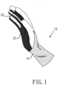
FIG. 1 is a schematic diagram showing a usage configuration of a glove structure. -
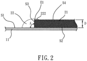
FIG. 2 is a section view of a partial structure of a glove structure. -
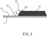
FIG. 3 is a section view of an obtuse angle structure of a glove structure. -
FIG. 4 is a section view of a sharp angle structure of the glove structure. -
FIG. 5 is a section view of a partial structure of the glove structure. -
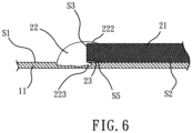
FIG. 6 is a section view of a partial structure of the glove structure according to the invention. -
FIG. 7 is a section view of a partial structure of the glove structure according to the invention. -
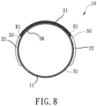
FIG. 8 is a section view of a glove structure. - The present disclosure mainly provides a glove structure. As shown in
FIG. 1 andFIG. 2 , aglove core 11 of aglove structure 10 is covered by at least apiece 21, and via thepiece 21, theglove structure 10 has a predetermined functional characteristic, such as non-slip, scratch-resistant, waterproof, thermal insulated or electricity insulated characteristic. - In the embodiment of the present disclosure, the
glove core 11 of theglove structure 10 can be made of cotton yarn, leather, plush, fiber, natural fiber, rayon, non-woven fabric, plastic or rubber, theglove core 11 can be a knitted glove, a sewing glove or a woven glove, and the material of thepiece 21 can be the same as that of theglove core 11. Or alternatively, the material of thepiece 21 can be different from that of theglove core 11. Theglove core 11 can comprise a palm portion and a finger portion, and the palm portion can comprise a palm piece, a palm side piece and a palm back piece while the finger portion can comprise a finger piece, a finger side piece and a finger back piece. Or alternatively, theglove core 11 can merely have the palm portion, and the finger portion is not an essential component of theglove core 11; or theglove core 11 can merely have the finger portion, and the palm portion is not an essential component of theglove core 11. It is noted that the palm portion, the finger portion, the palm piece, the palm side piece, the palm back piece, the finger piece, the finger side piece and the finger back piece are well known by the person with the ordinary skill in the art, and thus omitting the reference numbers of them. - Regarding the glove structure of the present disclosure, a bottom surface S2 of the
piece 21 is configured to cover an outer surface S1 of theglove core 11, and the glove structure is characterized in: the outer surface S1 has aninjection molding assembly 22 which fills a section S3 of thepiece 21. - Generally speaking, the
piece 21 is pre-cut to have a specific outline, a molding tool is next used to make thepiece 21 cover and located on a preset position of theglove core 11, and melted injection molding material fills the outer surface S1 of theglove core 11 and the section S3 of thepiece 21 via the molding tool. After the melted injection molding material is cooled down and shaped, theinjection molding assembly 22 which fills a section gap D between theglove core 11 and thepiece 21 is formed. - Accordingly, regarding the glove structure of the present disclosure, the
injection molding assembly 22 can mask section gap D between theglove core 11 and thepiece 21, and at the same time, the melted injection molding material is liquid to permeate into the outer surface S1 and the section S3 via the high pressure of the molding tool. The melted injection molding material thus flows to inner pores of the outer surface S1 and the section S3 for generating high adhesion of molecule winding of physical phenomenon or even a high bonding force of chemical bonding. Thus, even under the condition that the outer surface S1 of theglove core 11 and bottom surface S2 of thepiece 21 have a little adhesive force or no boding force, the piece 21 (i.e. the bottom surface S2) can be bound to the glove core 11 (i.e. the outer surface S1) since theinjection molding assembly 22 of the outer surface S1 fills the section S3. - Furthermore, the injection molding material is usually elastic material, and thus when an external force is applied on the
injection molding assembly 22 with the intend to separate theglove core 11 and thepiece 21 from the section gap D, the buffering characteristic of the elastic material resists again most of the external force, the probability of separating theglove core 11 and thepiece 21 from the section gap D is dramatically decreased, and the lifetime of theglove structure 10 is increased. The present disclosure merely uses littleinjection molding assembly 22 of the outer surface S1 to fill the section S3 of thepiece 21 to achieve the objective of bonding the piece 21 (i.e. the bottom surface S2) to the glove core 11 (i.e. the outer surface S1), and the thickness of thewhole glove structure 10 is maintained to a thickness summation of the thickness ofglove core 11 and the thickness of thepiece 21, without the heavy and thick disadvantages due to three-layer structure mentioned in the prior art. Since theinjection molding assembly 22 is little and small, it occupies less area of thepiece 21, and the original breathability if thepiece 21 is not affected by theinjection molding assembly 22. At the same time, by using the buffering characteristic of theinjection molding assembly 22, the damage of the external force can be eliminated, and thus the lifetime of theglove structure 10 is increased. To sum up, the present disclosure porvides postive and reliable means for preventing thepiece 21 from being separated from theglove core 11 via the section gap D, making the glove structure maintain its required function in long term, and increasing the quality and the lifetime of the glove structure. - Moreover, the
injection molding assembly 22 extends along the direction of the disposedpiece 21 to form an injectionmold overlapping section 222, the injectionmold overlapping section 222 of theinjection molding assembly 22 fills at least one portion of a top surface S4 of thepiece 21, and by utilizing the injectionmold overlapping section 222, a contacting area between theinjection molding assembly 22 and thepiece 21 is increased as well as the bonding or adhesive force of theinjection molding assembly 22 and thepiece 21, thus making thepiece 21 is more tightly bound to theglove core 11. The injectionmold overlapping section 222 and theinjection molding assembly 22 on the side of the section S3 form a fastener structure with a right angle for bonding thepiece 21, and thus, not only the bonding of thepiece 21 and theinjection molding assembly 22 is enhanced, but also the intend of the external force for separating thepiece 21 away from theinjection molding assembly 22 can be prevented. Especially, when the external force is the force being vertical to the direction of the outer surface S1 for separating thepiece 21 away from theinjection molding assembly 22, the injectionmold overlapping section 222 and theinjection molding assembly 22 on the side of the section S3 form a better fastener structure with a right angle for bonding thepiece 21, and preferably, the effect for resisting the external force which is intended to separate thepiece 21 away from theinjection molding assembly 22 is better when the injectionmold overlapping section 222 and theinjection molding assembly 22 are integrally formed. - The injection
mold overlapping section 222 of theinjection molding assembly 22 can merely fills a top surface edge E1 of the top surface S4 of thepiece 21. Such configuration can make the injectionmold overlapping section 222 increases the contacting area between theinjection molding assembly 22 and thepiece 21 to form the fastener structure with a right angle for bonding thepiece 21, and maintain the original breathability of thepiece 21 without being affected by theinjection molding assembly 22. - The outer surface S1 and the section S3 form an angle A on the
injection molding assembly 22. InFIG. 2 , the angle A is the right angle, i.e. the angle A is 90 degrees; inFIG. 3 , when the angle A is an obtuse angle, i.e. the angle A is larger than 90 degrees and less than 180 degrees, the section S3 has a beveled shape to make the contacting area between the section S3 and theinjection molding assembly 22 is larger than that when the angle A is the right angle; inFIG. 4 , when the angle A is a sharp angle, i.e. the angle A is larger than 0 degrees and less than 90 degrees, the section S3 has a beveled shape, the contacting area between the section S3 and theinjection molding assembly 22 is larger than that when the angle A is the right angle, an injectionmold holding section 221 is formed, and by using the injectionmold holding section 221, theinjection molding assembly 22 and the injectionmold overlapping section 222, a clamping effect for thepiece 21 is obtained. Therefore, in the embodiment ofFIG. 4 , the boding of theinjection molding assembly 22 and thepiece 21 is enhanced. - Referring to
FIG. 5 , as mentioned above, the molding tool is utilized to make thepiece 21 cover and be located on the preset position of theglove core 11, the bottom surface S2 of thepiece 21 in the embodiment is configured to have abonding layer 23. Thebonding layer 23 is made of adhesive material to make the bottom surface S2 of thepiece 21 adhered to the outer surface S1 of theglove core 11. Thebonding layer 23 can merely be disposed on a bottom surface edge E2 of the bottom surface S2 without coating the adhesive material on the whole bottom surface S2, so as to reduce the effect on the original function of thepiece 21, such as the breathability. Or alternatively, thebonding layer 23 on the bottom surface S2 can be coated in an discontinuous manner, for example, specific regions of the bottom surface S2 are coated with the adhesive material while other regions of the bottom surface S2 are not coated with the adhesive material, so as to reduce the effect on the original function of thepiece 21. - Referring to
FIG. 6 , as mentioned above, the molding tool can be utilized to make the melted injection molding material fill the outer surface S1 of theglove core 11 and the section S3 of thepiece 21, depending on material characteristics of different material of theglove core 11, the injection molding material of theinjection molding assembly 22 permeates into the disposedglove core 11 with a predetermined depth, and the interface boding effect (i.e. anchorage) of theinjection molding assembly 22 and theglove core 11 can be achieved, thus increasing the structure strength of the functional construction. Theinjection molding assembly 22 can permeate into the disposedglove core 11, and then extend underneath the bottom surface S2 of thepiece 21 to form an injectionmold clamping section 223 which is bound to bottom surface S2 or a bonding bottom surface S5 of thebonding layer 23. The injectionmold clamping section 223, theinjection molding assembly 22 and the injectionmold overlapping section 222 are formed for clamping and bonding thepiece 21, so as to enhance the bonding of theinjection molding assembly 22 and thepiece 21. It is noted that, an unexpected finding shows that since the injection molding material of theinjection molding assembly 22 permeates into the disposedglove core 11 with the predetermined depth, after the melted injection molding material is cooled down and shaped, the stiffness of theglove core 11 is unexpectedly increased. According to theory of Young's modulus, the resistance of deformation of theglove core 11 is unexpectedly increased, and at the same time, it is also found that within the applicable range of Hooke's law, the region which theglove core 11 disposed on theinjection molding assembly 22 is not slackened after wearing for a long term, maintains its original state as it is not used, and increases the durability and comfort of the whole glove structure. - Similarly, as shown in
FIG. 7 , theinjection molding assembly 22 can generate function characteristic different from those of theglove core 11 and thepiece 11 depending on the material characteristic of theinjection molding assembly 22. The function characteristic of theinjection molding assembly 22 can be the non-slip, scratch-resistant, waterproof, heat-insulating or insulating function, for example. Thus, theinjection molding assembly 22 extends to another side of the disposedpiece 21 to form an injectionmold function section 224, and the injectionmold function section 224 can have the non-slip, scratch-resistant, waterproof, heat-insulating or insulating function. In the embodiment, functions of theinjection molding assembly 22 and thepiece 21 are complementary to each other, for example, the good breathability of thepiece 21 can be used to enhance the poor breathability of theinjection molding assembly 22, and good wear resistance of theinjection molding assembly 22 can be used to enhance the poor wear resistance of thepiece 21. Or alternatively, the functions of theinjection molding assembly 22 and thepiece 21 can be multiplication functions, for example, theinjection molding assembly 22 is used to fill the section gap between theglove core 11 and thepiece 21, thus the probability of separating theglove core 11 andpiece 21 from the section gap is decreased, the thickness of the whole glove structure maintains about the thickness summation of the thickness of theglove core 11 and the thickness of thepiece 21, and the function of theinjection molding assembly 22 is replaced by that of thepiece 21. Therefore, the usage amount of theinjection molding assembly 22 can be reduced, and the glove structure will not have the thick, poor breathability and heavy disadvantages due to the three-layer structure as mentioned in the prior art. - Specifically, the glove structure of the present disclosure can be widely applied in gloves to produce different functions, for example, anti-slip, scratch-resistant, waterproof, heat-insulating, insulating and even reflective, warning and other functions.
- Referring to
FIG. 8 , in theglove structure 10 of the present disclosure, theinjection molding assembly 22 which covers thepiece 21 of theglove core 11 and fills theglove core 11 covers more than 50% of a perimeter of a glove core section S6 of theglove core 11, or thepiece 21 independently covers more than 50% of the perimeter of the glove core section S6. By using thepiece 21 and theinjection molding assembly 22, the toughness of theglove core 11 is increased, and the protection safety of wearing theglove structure 10 is also increased. When the user wears theglove structure 10 of the present disclosure, a pressure force toward outside is induced to spread theglove core 11 toward outside, as blowing the balloon to make it inflated. Thepiece 21 adhered to theglove core 11 and theinjection molding assembly 22 generate a strain force and a pressure force toward inside, wherein the pressure force toward inside has the direction being opposite to the pressure forces toward outside, and has the force amount same as that of the pressure forces toward outside, so as to resist the pressure forces toward outside to form a balance state. The above design which more than 50% of the perimeter of the glove core section S6 is covered can form a curved surface when theglove structure 10 is worn. As the inflated balloon, an equivalent force of strain forces of portions on the curved surface of the balloon directs to the inside of the curved surface of the balloon, and the direction of the equivalent force directing to the inside of the curved surface of the present disclosure is the same as the adhesive directions of "theglove core 11 andpiece 21" and "theglove core 11 and theinjection molding assembly 22", i.e. the directions direct to the inner central direction of the glove core section S6. The strain forces of thepiece 21 and theinjection molding assembly 22 can be used be converted to the forces for enhancing the bonding of "theglove core 11 andpiece 21" and "theglove core 11 and theinjection molding assembly 22" via the curved surface of wearing the glove structure. Thus, not only theglove structure 10 can obtain the better function characteristic, but also the mechanic structure strength of thewhole glove structure 10 is getting better. - As shown in
FIG. 8 , thepiece 21 on the glove core section S6 can have the two section S3, wherein any one of sections S3 is disposed on the palm piece, a interconnection of the palm piece and the palm side piece, the palm side piece, a interconnection of the palm side piece and the palm back piece, the palm back piece, the finger piece, a interconnection of the finger piece and the finger side piece, the finger side piece, a interconnection of the finger side piece and the finger back piece, or the finger back piece of theglove core 11; and another one section S3 extended along thepiece 21 is disposed on the palm piece, a interconnection of the palm piece and the palm side piece, the palm side piece, a interconnection of the palm side piece and the palm back piece, the palm back piece, the finger piece, a interconnection of the finger piece and the finger side piece, the finger side piece, a interconnection of the finger side piece and the finger back piece, or the finger back piece of theglove core 11. It is noted that the palm portion, the finger portion, the palm piece, the palm side piece, the palm back piece, the finger piece, the finger side piece and the finger back piece are well known by the person with the ordinary skill in the art, and thus omitting the reference numbers of them. - It is also noted that, another unexpected finding shows that the shaping of the
injection molding assembly 22 is to melt the injection molding material to the liquid, make the liquid flow into the space between an inner and outer three-dimensional hand shape molding tools which simulates the human hand shape, and make the liquid permeate into the outer surface S1 and the section S3 by using the high pressure in the molding tools. After the melted injection molding material is cooled down and shaped, as shown inFIG. 8 , theinjection molding assembly 22 is formed with a curved surface shape. Since the melted injection molding material is cooled down to be shaped, the stiffness of theglove core 11 is unexpectedly increased. According to theory of Young's modulus, the resistance of deformation of theglove core 11 is unexpectedly increased. Thus, even the external force is applied to the curved surface shape, for example, the pressure force generated by stacking the glove structures, when the curved surface shape is under the pressure force or the pressure force is released, within the applicable range of Hooke's law, the curved surface shape restore to its original shape. The formation and maintenance of the curved surface shape unexpectedly makes theglove structure 10 have a three-dimensional structure. The curved surface shape covers any one portion of the glove core to present the three-dimensional structure. Preferably, when the curved surface shape covers the palm side piece or the finger side piece of theglove core 11, the three-dimensional structure is presented. More preferably, when the curved surface shape covers "the palm side piece and the palm piece", "the palm side piece and the palm back piece", "the finger side piece and the finger piece" or "the finger side piece and the finger back piece" of theglove core 11, the three-dimensional structure is presented. Most preferably, when the curved surface shape covers "the palm back piece, the palm side piece and the palm piece" or "the finger back piece, the finger side piece and the finger piece" of theglove core 11, the three-dimensional structure is presented. The curved surface shape of theinjection molding assembly 22 unexpectedly makes the top surface edge El of thepiece 21 bound to theinjection molding assembly 22 also be a curved surface shape, and this further makes theglove structure 10 more present the three-dimensional structure. - Compared to the prior art, the present disclosure utilizes the injection molding assembly to mask the section gap between the piece and the glove core, and to achieve the objective of bonding the piece, thus providing postive and reliable means for preventing the piece from being separated from the glove core, making the glove structure maintain its required function in long term, increasing the quality of the glove structure. Especially, the injection molding assembly, the piece and the glove core of the glove structure with different functions can be stably bound to each other, the function characteristic of the glove structure is enhanced, the lifetime of the glove structure is dramatically increased, and the glove structure has a curved surface shape to present its three-dimensional shape.
Claims (11)
- A glove structure (10), at least comprising: a glove core (11) and a piece (21),wherein a bottom surface (S2) of the piece (21) covers an outer surface (S1) of the glove core (11), the outer surface (S1) is configured to have an injection molding assembly (22), the injection molding assembly (22) fills a section (S3) of the piece (21)wherein the injection molding assembly (22) extends to a top surface (S4) of the piece (21) to form an injection mold overlapping section (222), and the injection mold overlapping section (222) merely fills a top surface edge (E1) of the top surface (S4), wherein the bottom surface (S2) of the piece (21) is configured to have a bonding layer (23), characterized in that the injection molding assembly (22) extends underneath the bottom surface (S2) to form an injection mold clamping section (223), the injection mold clamping section (223) is adhered to a bonding bottom surface (S5) of the bonding layer (23).
- The glove structure (10) according to claim 1, wherein the bonding layer (23) is merely disposed on a bottom surface edge (E2) of the bottom surface (S2).
- The glove structure (10) according to claim 1, wherein the piece (21) and the injection molding assembly (22) cover more than 50% of a perimeter of a glove core section (S6) of the glove core (11).
- The glove structure (10) according to claim 3, wherein the piece (21) covers more than 50% of the perimeter of the glove core section (S6) of the glove core (11).
- The glove structure (10) according to claim 1, wherein the glove core (11) has a palm piece, a palm side piece, a palm back piece, a finger piece, a finger side piece and a finger back piece; the piece (21) disposed on a glove core section (S6) of the glove core (11) has the two sections (S3), wherein any one of sections (S3) is disposed on the palm piece, a interconnection of the palm piece and the palm side piece, the palm side piece, a interconnection of the palm side piece and the palm back piece, the palm back piece, the finger piece, a interconnection of the finger piece and the finger side piece, the finger side piece, a interconnection of the finger side piece and the finger back piece, or the finger back piece of the glove core (11); and another one section (S3) extending along the piece (21) is disposed on the palm piece, a interconnection of the palm piece and the palm side piece, the palm side piece, a interconnection of the palm side piece and the palm back piece, the palm back piece, the finger piece, a interconnection of the finger piece and the finger side piece, the finger side piece, a interconnection of the finger side piece and the finger back piece, or the finger back piece of the glove core (11).
- The glove structure (10) according to claim 1, wherein the injection molding assembly (22) has a curved surface shape to cover any one portion of the glove core (11).
- The glove structure (10) according to claim 6, wherein the glove core (11) has a palm side piece, and the curved surface shape covers the palm side piece, or the glove core (11) has a finger side piece, and the curved surface shape covers the finger side piece.
- The glove structure (10) according to claim 6, wherein the glove core (11) has a palm piece, a palm side piece and a palm back piece, and the curved surface shape covers "the palm side piece and the palm piece" or "the palm side piece and the palm back piece".
- The glove structure (10) according to claim 6, wherien the glove core (11) has a finger piece, a finger side piece and a finger back piece, and the curved surface shape covers "the finger side piece and the finger piece" or "the finger side piece and the finger back piece".
- The glove structure (10) according to claim 6, wherein the glove core (11) has a palm piece, a palm side piece and a palm back piece, and the curved surface shape covers the palm back piece, the palm side piece and the palm piece.
- The glove structure (10) according to claim 6, wherein the glove core (11) has a finger piece, a finger side piece and a finger back piece, and the curved surface shape covers the finger back piece, the finger side piece and the finger piece.
Priority Applications (2)
| Application Number | Priority Date | Filing Date | Title |
|---|---|---|---|
| RS20231267A RS65432B1 (en) | 2017-01-12 | 2018-01-09 | Glove structure |
| HRP20231647TT HRP20231647T1 (en) | 2017-01-12 | 2018-01-09 | Glove structure |
Applications Claiming Priority (2)
| Application Number | Priority Date | Filing Date | Title |
|---|---|---|---|
| CN201710020727.XA CN108294382B (en) | 2017-01-12 | 2017-01-12 | glove construction |
| PCT/CN2018/071895 WO2018130138A1 (en) | 2017-01-12 | 2018-01-09 | Glove structure |
Publications (4)
| Publication Number | Publication Date |
|---|---|
| EP3581049A1 EP3581049A1 (en) | 2019-12-18 |
| EP3581049A4 EP3581049A4 (en) | 2020-10-28 |
| EP3581049C0 EP3581049C0 (en) | 2023-09-27 |
| EP3581049B1 true EP3581049B1 (en) | 2023-09-27 |
Family
ID=62839824
Family Applications (1)
| Application Number | Title | Priority Date | Filing Date |
|---|---|---|---|
| EP18739261.8A Active EP3581049B1 (en) | 2017-01-12 | 2018-01-09 | Glove structure |
Country Status (17)
| Country | Link |
|---|---|
| US (1) | US11399582B2 (en) |
| EP (1) | EP3581049B1 (en) |
| JP (1) | JP7169277B2 (en) |
| KR (1) | KR102536193B1 (en) |
| CN (1) | CN108294382B (en) |
| AU (1) | AU2018207710B2 (en) |
| CA (1) | CA3049315C (en) |
| CL (1) | CL2019001941A1 (en) |
| ES (1) | ES2966298T3 (en) |
| HR (1) | HRP20231647T1 (en) |
| HU (1) | HUE065314T2 (en) |
| MX (1) | MX2019008360A (en) |
| PL (1) | PL3581049T3 (en) |
| RS (1) | RS65432B1 (en) |
| RU (1) | RU2750982C2 (en) |
| WO (1) | WO2018130138A1 (en) |
| ZA (1) | ZA201904806B (en) |
Families Citing this family (8)
| Publication number | Priority date | Publication date | Assignee | Title |
|---|---|---|---|---|
| US12156552B2 (en) | 2013-07-22 | 2024-12-03 | Summit Glove Inc. | Protective device for use with a glove |
| US11925222B2 (en) | 2015-06-19 | 2024-03-12 | Summit Glove Inc. | Safety glove with fingertip protective member |
| US12616259B2 (en) | 2015-04-24 | 2026-05-05 | Summit Glove Inc. | Glove with longitudinal finger stays and textured finger and thumb crotches |
| US12446639B2 (en) | 2015-04-24 | 2025-10-21 | Summit Glove Inc. | Drug resistant glove |
| USD893129S1 (en) * | 2016-05-25 | 2020-08-18 | Summit Glove Inc. | Patterned glove with a flared cuff |
| US11399583B2 (en) * | 2019-07-03 | 2022-08-02 | Niphan Tangpirounthum | Glove and a method for producing the same |
| JP7745198B2 (en) * | 2021-09-02 | 2025-09-29 | 株式会社サンパック | Gloves and their manufacturing method |
| US12178268B2 (en) * | 2022-07-27 | 2024-12-31 | Summit Glove Inc. | Protective device for use with a glove |
Family Cites Families (12)
| Publication number | Priority date | Publication date | Assignee | Title |
|---|---|---|---|---|
| US7469427B2 (en) * | 2005-06-30 | 2008-12-30 | Kimberly-Clark Worldwide, Inc. | Stretchable and permeable non-woven protective gloves |
| US9555567B2 (en) * | 2007-07-16 | 2017-01-31 | Madgrip Holdings, Llc | Utility glove |
| US20090070916A1 (en) * | 2007-09-13 | 2009-03-19 | Mikhail Kassam | Personal protective garment |
| CN101406331A (en) * | 2008-11-24 | 2009-04-15 | 杭州福星工贸有限公司 | Clothing seamless splicing structure and splicing method thereof |
| US20120227158A1 (en) | 2011-03-11 | 2012-09-13 | Ansell Limited | Glove having injection molded components |
| EP2641493B1 (en) * | 2012-03-20 | 2014-09-10 | W.L. Gore & Associates GmbH | Breathable dip glove |
| CN103535940A (en) * | 2013-11-12 | 2014-01-29 | 上海金枫裕手套有限公司 | Manufacturing method for molding gloves in injection mode with knitted or sewed glove cores |
| CN104621803B (en) * | 2013-11-12 | 2017-05-24 | 广西喜诺盛手套有限公司 | glove structure |
| CN204930473U (en) * | 2015-08-04 | 2016-01-06 | 广西北海喜诺盛手套科技有限公司 | Gloves |
| CN204930476U (en) * | 2015-08-04 | 2016-01-06 | 广西北海利博盛安全用品有限公司 | Glove structure |
| US20180035733A1 (en) * | 2016-08-02 | 2018-02-08 | Charles Waxter | Electrically Insulated Glove Assembly |
| CN206443266U (en) * | 2017-01-12 | 2017-08-29 | 上海金枫裕手套有限公司 | Glove structure |
-
2017
- 2017-01-12 CN CN201710020727.XA patent/CN108294382B/en active Active
-
2018
- 2018-01-09 AU AU2018207710A patent/AU2018207710B2/en active Active
- 2018-01-09 HR HRP20231647TT patent/HRP20231647T1/en unknown
- 2018-01-09 HU HUE18739261A patent/HUE065314T2/en unknown
- 2018-01-09 RS RS20231267A patent/RS65432B1/en unknown
- 2018-01-09 PL PL18739261.8T patent/PL3581049T3/en unknown
- 2018-01-09 MX MX2019008360A patent/MX2019008360A/en unknown
- 2018-01-09 RU RU2019125194A patent/RU2750982C2/en active
- 2018-01-09 EP EP18739261.8A patent/EP3581049B1/en active Active
- 2018-01-09 ES ES18739261T patent/ES2966298T3/en active Active
- 2018-01-09 WO PCT/CN2018/071895 patent/WO2018130138A1/en not_active Ceased
- 2018-01-09 CA CA3049315A patent/CA3049315C/en active Active
- 2018-01-09 JP JP2019537349A patent/JP7169277B2/en active Active
- 2018-01-09 US US16/476,178 patent/US11399582B2/en active Active
- 2018-01-09 KR KR1020197023672A patent/KR102536193B1/en active Active
-
2019
- 2019-07-11 CL CL2019001941A patent/CL2019001941A1/en unknown
- 2019-07-22 ZA ZA2019/04806A patent/ZA201904806B/en unknown
Also Published As
| Publication number | Publication date |
|---|---|
| EP3581049A4 (en) | 2020-10-28 |
| US11399582B2 (en) | 2022-08-02 |
| MX2019008360A (en) | 2019-09-16 |
| KR20200007767A (en) | 2020-01-22 |
| PL3581049T3 (en) | 2024-04-08 |
| RU2750982C2 (en) | 2021-07-07 |
| RU2019125194A (en) | 2021-02-12 |
| BR112019014504A2 (en) | 2020-02-18 |
| CN108294382B (en) | 2023-05-09 |
| CA3049315A1 (en) | 2018-07-19 |
| HUE065314T2 (en) | 2024-05-28 |
| HRP20231647T1 (en) | 2024-03-15 |
| CL2019001941A1 (en) | 2020-02-28 |
| CN108294382A (en) | 2018-07-20 |
| AU2018207710A1 (en) | 2019-07-25 |
| EP3581049A1 (en) | 2019-12-18 |
| RU2019125194A3 (en) | 2021-05-26 |
| JP2020504249A (en) | 2020-02-06 |
| RS65432B1 (en) | 2024-05-31 |
| AU2018207710B2 (en) | 2022-06-23 |
| JP7169277B2 (en) | 2022-11-10 |
| US20190343200A1 (en) | 2019-11-14 |
| ZA201904806B (en) | 2021-02-24 |
| CA3049315C (en) | 2023-01-24 |
| ES2966298T3 (en) | 2024-04-19 |
| EP3581049C0 (en) | 2023-09-27 |
| KR102536193B1 (en) | 2023-05-24 |
| WO2018130138A1 (en) | 2018-07-19 |
Similar Documents
| Publication | Publication Date | Title |
|---|---|---|
| AU2018207710B2 (en) | Glove structure | |
| US8881313B2 (en) | Molded articles of clothing with non-molded components | |
| EA028487B1 (en) | Cushioning pad | |
| US9399164B2 (en) | Cycling suit with a seat pad | |
| WO2014159827A1 (en) | Integrated protective garment ensemble | |
| WO2017128569A1 (en) | Protective work glove and manufacturing process therefor | |
| US7721348B2 (en) | Protective element | |
| US12588720B2 (en) | Impact protector | |
| US12310436B2 (en) | Glove structure and its manufacturing method | |
| CN206443266U (en) | Glove structure | |
| CN206968140U (en) | A kind of cut resistant protective gloves | |
| WO2022243859A1 (en) | Protective garment | |
| CN114947300B (en) | Composite footwear and glove articles | |
| EP4049548B1 (en) | Composite items of footwear and handwear | |
| JP4702709B2 (en) | Every time underground | |
| IT202000015772A1 (en) | ITEM OF PROTECTIVE CLOTHING | |
| BR112019014504B1 (en) | GLOVE STRUCTURE | |
| JP3139589U (en) | High-strength work gloves | |
| EP3539398A1 (en) | Protective equipment for wasp nest removal | |
| KR20130093863A (en) | Adhesion pad for supporting a shoulder | |
| JPH08196307A (en) | Rubber-soled sock | |
| PL70310Y1 (en) | Protective jacket | |
| CN109452701A (en) | A kind of disposition clothes |
Legal Events
| Date | Code | Title | Description |
|---|---|---|---|
| STAA | Information on the status of an ep patent application or granted ep patent |
Free format text: STATUS: THE INTERNATIONAL PUBLICATION HAS BEEN MADE |
|
| PUAI | Public reference made under article 153(3) epc to a published international application that has entered the european phase |
Free format text: ORIGINAL CODE: 0009012 |
|
| STAA | Information on the status of an ep patent application or granted ep patent |
Free format text: STATUS: REQUEST FOR EXAMINATION WAS MADE |
|
| PUAB | Information related to the publication of an a document modified or deleted |
Free format text: ORIGINAL CODE: 0009199EPPU |
|
| PUAI | Public reference made under article 153(3) epc to a published international application that has entered the european phase |
Free format text: ORIGINAL CODE: 0009012 |
|
| 17P | Request for examination filed |
Effective date: 20190801 |
|
| AK | Designated contracting states |
Kind code of ref document: A1 Designated state(s): AL AT BE BG CH CY CZ DE DK EE ES FI FR GB GR HR HU IE IS IT LI LT LU LV MC MK MT NL NO PL PT RO RS SE SI SK SM TR |
|
| AX | Request for extension of the european patent |
Extension state: BA ME |
|
| DAV | Request for validation of the european patent (deleted) | ||
| DAX | Request for extension of the european patent (deleted) | ||
| A4 | Supplementary search report drawn up and despatched |
Effective date: 20200929 |
|
| RIC1 | Information provided on ipc code assigned before grant |
Ipc: A41D 19/00 20060101ALI20200923BHEP Ipc: A41D 19/02 20060101AFI20200923BHEP |
|
| STAA | Information on the status of an ep patent application or granted ep patent |
Free format text: STATUS: EXAMINATION IS IN PROGRESS |
|
| 17Q | First examination report despatched |
Effective date: 20210910 |
|
| REG | Reference to a national code |
Ref country code: DE Free format text: PREVIOUS MAIN CLASS: A41D0019020000 Ref country code: DE Ref legal event code: R079 Ref document number: 602018058278 Country of ref document: DE Free format text: PREVIOUS MAIN CLASS: A41D0019020000 Ipc: A41D0019000000 |
|
| RIC1 | Information provided on ipc code assigned before grant |
Ipc: B29D 99/00 20100101ALI20230109BHEP Ipc: A41D 19/02 19680901ALI20230109BHEP Ipc: A41D 19/015 20000101ALI20230109BHEP Ipc: A41D 19/00 19680901AFI20230109BHEP |
|
| GRAP | Despatch of communication of intention to grant a patent |
Free format text: ORIGINAL CODE: EPIDOSNIGR1 |
|
| STAA | Information on the status of an ep patent application or granted ep patent |
Free format text: STATUS: GRANT OF PATENT IS INTENDED |
|
| INTG | Intention to grant announced |
Effective date: 20230412 |
|
| GRAS | Grant fee paid |
Free format text: ORIGINAL CODE: EPIDOSNIGR3 |
|
| GRAA | (expected) grant |
Free format text: ORIGINAL CODE: 0009210 |
|
| STAA | Information on the status of an ep patent application or granted ep patent |
Free format text: STATUS: THE PATENT HAS BEEN GRANTED |
|
| AK | Designated contracting states |
Kind code of ref document: B1 Designated state(s): AL AT BE BG CH CY CZ DE DK EE ES FI FR GB GR HR HU IE IS IT LI LT LU LV MC MK MT NL NO PL PT RO RS SE SI SK SM TR |
|
| RAP3 | Party data changed (applicant data changed or rights of an application transferred) |
Owner name: JOHN ENGINE SPORTS PRODUCTS INC |
|
| REG | Reference to a national code |
Ref country code: GB Ref legal event code: FG4D |
|
| REG | Reference to a national code |
Ref country code: CH Ref legal event code: EP |
|
| REG | Reference to a national code |
Ref country code: DE Ref legal event code: R096 Ref document number: 602018058278 Country of ref document: DE |
|
| REG | Reference to a national code |
Ref country code: IE Ref legal event code: FG4D |
|
| U01 | Request for unitary effect filed |
Effective date: 20231023 |
|
| U07 | Unitary effect registered |
Designated state(s): AT BE BG DE DK EE FI FR IT LT LU LV MT NL PT SE SI Effective date: 20231027 |
|
| REG | Reference to a national code |
Ref country code: NO Ref legal event code: T2 Effective date: 20230927 |
|
| REG | Reference to a national code |
Ref country code: GR Ref legal event code: EP Ref document number: 20230402579 Country of ref document: GR Effective date: 20240209 Ref country code: SK Ref legal event code: T3 Ref document number: E 43131 Country of ref document: SK |
|
| U20 | Renewal fee for the european patent with unitary effect paid |
Year of fee payment: 7 Effective date: 20240124 |
|
| PG25 | Lapsed in a contracting state [announced via postgrant information from national office to epo] |
Ref country code: IS Free format text: LAPSE BECAUSE OF FAILURE TO SUBMIT A TRANSLATION OF THE DESCRIPTION OR TO PAY THE FEE WITHIN THE PRESCRIBED TIME-LIMIT Effective date: 20240127 |
|
| REG | Reference to a national code |
Ref country code: ES Ref legal event code: FG2A Ref document number: 2966298 Country of ref document: ES Kind code of ref document: T3 Effective date: 20240419 |
|
| PG25 | Lapsed in a contracting state [announced via postgrant information from national office to epo] |
Ref country code: SM Free format text: LAPSE BECAUSE OF FAILURE TO SUBMIT A TRANSLATION OF THE DESCRIPTION OR TO PAY THE FEE WITHIN THE PRESCRIBED TIME-LIMIT Effective date: 20230927 Ref country code: IS Free format text: LAPSE BECAUSE OF FAILURE TO SUBMIT A TRANSLATION OF THE DESCRIPTION OR TO PAY THE FEE WITHIN THE PRESCRIBED TIME-LIMIT Effective date: 20240127 |
|
| REG | Reference to a national code |
Ref country code: HU Ref legal event code: AG4A Ref document number: E065314 Country of ref document: HU |
|
| REG | Reference to a national code |
Ref country code: DE Ref legal event code: R097 Ref document number: 602018058278 Country of ref document: DE |
|
| PLBE | No opposition filed within time limit |
Free format text: ORIGINAL CODE: 0009261 |
|
| STAA | Information on the status of an ep patent application or granted ep patent |
Free format text: STATUS: NO OPPOSITION FILED WITHIN TIME LIMIT |
|
| PG25 | Lapsed in a contracting state [announced via postgrant information from national office to epo] |
Ref country code: MC Free format text: LAPSE BECAUSE OF FAILURE TO SUBMIT A TRANSLATION OF THE DESCRIPTION OR TO PAY THE FEE WITHIN THE PRESCRIBED TIME-LIMIT Effective date: 20230927 |
|
| PG25 | Lapsed in a contracting state [announced via postgrant information from national office to epo] |
Ref country code: MC Free format text: LAPSE BECAUSE OF FAILURE TO SUBMIT A TRANSLATION OF THE DESCRIPTION OR TO PAY THE FEE WITHIN THE PRESCRIBED TIME-LIMIT Effective date: 20230927 |
|
| 26N | No opposition filed |
Effective date: 20240628 |
|
| U20 | Renewal fee for the european patent with unitary effect paid |
Year of fee payment: 8 Effective date: 20250128 |
|
| PG25 | Lapsed in a contracting state [announced via postgrant information from national office to epo] |
Ref country code: CY Free format text: LAPSE BECAUSE OF FAILURE TO SUBMIT A TRANSLATION OF THE DESCRIPTION OR TO PAY THE FEE WITHIN THE PRESCRIBED TIME-LIMIT; INVALID AB INITIO Effective date: 20180109 |
|
| PGFP | Annual fee paid to national office [announced via postgrant information from national office to epo] |
Ref country code: GB Payment date: 20251218 Year of fee payment: 9 |
|
| PGFP | Annual fee paid to national office [announced via postgrant information from national office to epo] |
Ref country code: NO Payment date: 20251222 Year of fee payment: 9 |
|
| PGFP | Annual fee paid to national office [announced via postgrant information from national office to epo] |
Ref country code: GR Payment date: 20251219 Year of fee payment: 9 |
|
| PGFP | Annual fee paid to national office [announced via postgrant information from national office to epo] |
Ref country code: IE Payment date: 20251218 Year of fee payment: 9 |
|
| U20 | Renewal fee for the european patent with unitary effect paid |
Year of fee payment: 9 Effective date: 20251218 |
|
| PGFP | Annual fee paid to national office [announced via postgrant information from national office to epo] |
Ref country code: PL Payment date: 20251222 Year of fee payment: 9 |
|
| PGFP | Annual fee paid to national office [announced via postgrant information from national office to epo] |
Ref country code: SK Payment date: 20251223 Year of fee payment: 9 |
|
| PGFP | Annual fee paid to national office [announced via postgrant information from national office to epo] |
Ref country code: RS Payment date: 20251224 Year of fee payment: 9 |
|
| REG | Reference to a national code |
Ref country code: CH Ref legal event code: U11 Free format text: ST27 STATUS EVENT CODE: U-0-0-U10-U11 (AS PROVIDED BY THE NATIONAL OFFICE) Effective date: 20260201 |
|
| PGFP | Annual fee paid to national office [announced via postgrant information from national office to epo] |
Ref country code: HU Payment date: 20251218 Year of fee payment: 9 |
|
| PGFP | Annual fee paid to national office [announced via postgrant information from national office to epo] |
Ref country code: ES Payment date: 20260226 Year of fee payment: 9 |
|
| PGFP | Annual fee paid to national office [announced via postgrant information from national office to epo] |
Ref country code: HR Payment date: 20260123 Year of fee payment: 9 |
|
| PGFP | Annual fee paid to national office [announced via postgrant information from national office to epo] |
Ref country code: RO Payment date: 20260105 Year of fee payment: 9 |
|
| PGFP | Annual fee paid to national office [announced via postgrant information from national office to epo] |
Ref country code: TR Payment date: 20260108 Year of fee payment: 9 |
|
| PGFP | Annual fee paid to national office [announced via postgrant information from national office to epo] |
Ref country code: CH Payment date: 20260201 Year of fee payment: 9 Ref country code: CZ Payment date: 20260105 Year of fee payment: 9 |