EP3581015A1 - Unitary component crop ramp and belt support - Google Patents
Unitary component crop ramp and belt support Download PDFInfo
- Publication number
- EP3581015A1 EP3581015A1 EP19179043.5A EP19179043A EP3581015A1 EP 3581015 A1 EP3581015 A1 EP 3581015A1 EP 19179043 A EP19179043 A EP 19179043A EP 3581015 A1 EP3581015 A1 EP 3581015A1
- Authority
- EP
- European Patent Office
- Prior art keywords
- belt
- belt support
- crop ramp
- component
- generally planar
- Prior art date
- Legal status (The legal status is an assumption and is not a legal conclusion. Google has not performed a legal analysis and makes no representation as to the accuracy of the status listed.)
- Granted
Links
Images



Classifications
-
- A—HUMAN NECESSITIES
- A01—AGRICULTURE; FORESTRY; ANIMAL HUSBANDRY; HUNTING; TRAPPING; FISHING
- A01D—HARVESTING; MOWING
- A01D57/00—Delivering mechanisms for harvesters or mowers
- A01D57/20—Delivering mechanisms for harvesters or mowers with conveyor belts
-
- A—HUMAN NECESSITIES
- A01—AGRICULTURE; FORESTRY; ANIMAL HUSBANDRY; HUNTING; TRAPPING; FISHING
- A01D—HARVESTING; MOWING
- A01D47/00—Headers for topping of plants, e.g. stalks with ears
-
- A—HUMAN NECESSITIES
- A01—AGRICULTURE; FORESTRY; ANIMAL HUSBANDRY; HUNTING; TRAPPING; FISHING
- A01D—HARVESTING; MOWING
- A01D34/00—Mowers; Mowing apparatus of harvesters
- A01D34/01—Mowers; Mowing apparatus of harvesters characterised by features relating to the type of cutting apparatus
- A01D34/02—Mowers; Mowing apparatus of harvesters characterised by features relating to the type of cutting apparatus having reciprocating cutters
- A01D34/40—Other details
-
- A—HUMAN NECESSITIES
- A01—AGRICULTURE; FORESTRY; ANIMAL HUSBANDRY; HUNTING; TRAPPING; FISHING
- A01D—HARVESTING; MOWING
- A01D41/00—Combines, i.e. harvesters or mowers combined with threshing devices
- A01D41/12—Details of combines
- A01D41/14—Mowing tables
-
- A—HUMAN NECESSITIES
- A01—AGRICULTURE; FORESTRY; ANIMAL HUSBANDRY; HUNTING; TRAPPING; FISHING
- A01D—HARVESTING; MOWING
- A01D61/00—Elevators or conveyors for binders or combines
- A01D61/002—Elevators or conveyors for binders or combines transversal conveying devices
-
- A—HUMAN NECESSITIES
- A01—AGRICULTURE; FORESTRY; ANIMAL HUSBANDRY; HUNTING; TRAPPING; FISHING
- A01D—HARVESTING; MOWING
- A01D34/00—Mowers; Mowing apparatus of harvesters
- A01D34/01—Mowers; Mowing apparatus of harvesters characterised by features relating to the type of cutting apparatus
- A01D34/02—Mowers; Mowing apparatus of harvesters characterised by features relating to the type of cutting apparatus having reciprocating cutters
- A01D34/03—Mowers; Mowing apparatus of harvesters characterised by features relating to the type of cutting apparatus having reciprocating cutters mounted on a vehicle, e.g. a tractor, or drawn by an animal or a vehicle
- A01D34/04—Mowers; Mowing apparatus of harvesters characterised by features relating to the type of cutting apparatus having reciprocating cutters mounted on a vehicle, e.g. a tractor, or drawn by an animal or a vehicle with cutters at the front
- A01D34/046—Mowers; Mowing apparatus of harvesters characterised by features relating to the type of cutting apparatus having reciprocating cutters mounted on a vehicle, e.g. a tractor, or drawn by an animal or a vehicle with cutters at the front drawn by an animal or a vehicle
Definitions
- the present disclosure relates generally to agricultural harvesting equipment. More particularly, it relates to agricultural harvesting heads having reciprocating knives and conveyor belts, and a unitary crop ramp and belt support component for conveying crop from the reciprocating knives to the conveyor belts.
- Grain harvesting operations for crops such as wheat, soybeans, and rice are often completed by agricultural machines that include multiple reciprocating knives at the leading edge of the machine.
- the reciprocating knives sever the crop plants at their roots, permitting the harvested crops to fall onto one or more conveyor belts.
- a crop ramp is provided that ensures that harvested crop material is effectively conveyed to an exterior surface of a conveyor belt.
- a crop ramp component design that supports and protects the conveyor belt, prevents the ingress of foreign objects into the agricultural harvesting head, and helps seal against crop losses would therefore be useful.
- a crop ramp and belt support component for an agricultural harvesting head.
- the crop ramp and belt support component includes a forward portion, a rear portion, and a belt support portion that are generally planar.
- the forward portion is inclined relative to the rear portion, and the rear portion extends from the forward portion.
- the belt support portion is substantially parallel to the rear portion and is configured to extend at least partially below an interior surface of a belt conveyor.
- the forward portion, the rear portion, and the belt support portion are fabricated as a unitary component.
- the unitary component may be fabricated from ultra-high-molecular-weight polyethylene.
- the unitary component may be fabricated using an extrusion process.
- the unitary component may have a substantially constant extruded wall thickness.
- the extruded wall thickness may range from 3 mm to 10 mm.
- the crop ramp and belt support component may include a belt overhang portion that is generally planar and configured to extend at least partially above an exterior surface of the belt conveyor.
- the belt overhang portion may be substantially parallel to the belt support portion.
- the region that the belt overhang portion overlaps the exterior surface of the belt conveyor may range from 10 mm to 12 mm.
- the crop ramp and belt support component may include a bevel portion that is generally planar and inclined relative to the belt support portion. The angle of inclination between the belt support portion and the bevel portion may be approximately 30 degrees.
- an agricultural harvesting head in accordance with another aspect of the invention, includes a frame that extends laterally, a reciprocating knife that is supported on the frame, a belt conveyor that is supported on the frame and driven in a lateral direction, and a crop ramp and belt support component.
- the crop ramp and belt support component includes a forward portion, a rear portion, and a belt support portion that are generally planar.
- the forward portion is inclined relative to the rear portion, and the rear portion extends from the forward portion.
- the belt support portion is substantially parallel to the rear portion and is configured to extend at least partially below an interior surface of a belt conveyor.
- the forward portion, the rear portion, and the belt support portion are fabricated as a unitary component.
- the crop ramp and belt support component may include a belt overhang portion that is generally planar and configured to extend at least partially above an exterior surface of the belt conveyor.
- the belt overhang portion may be substantially parallel to the belt support portion.
- the region that the belt overhang portion overlaps the exterior surface of the belt conveyor may range from 10 mm to 12 mm.
- the crop ramp and belt support component may include a bevel portion that is generally planar and inclined relative to the belt support portion. The angle of inclination between the belt support portion and the bevel portion may be approximately 30 degrees.
- a method of fabricating a crop ramp and belt support component for an agricultural harvesting head includes providing a forward portion that is generally planar, providing a rear portion that is generally planar and that extends from the forward portion, the forward portion inclined relative to the rear portion, and providing a belt support portion that is generally planar and substantially parallel to the rear portion.
- the belt support portion is configured to extend at least partially below an interior surface of a belt conveyor and the forward portion, the rear portion, and the belt support portion form a unitary component.
- the method may include providing a belt overhang portion that is generally planar and configured to extend at least partially above an exterior surface of the belt conveyor.
- the belt overhang portion may be substantially parallel to the belt support portion.
- the method may include providing a bevel portion that is generally planar and inclined relative to the belt support portion. The angle of inclination between the belt support portion and the bevel portion may be approximately 30 degrees.
- a unitary crop ramp and belt support component is depicted, according to various embodiments.
- One or more conveyor belts are often utilized to transfer harvested crops from a cutting implement to a collecting device (e.g., an agricultural combine).
- a crop ramp is situated between the cutting implement and the conveyor belts to provide a smooth path of travel for the crops.
- the unitary design of the crop ramp and belt support of the present disclosure helps seal against crop losses, prevents ingress of foreign objects into critical moving parts, and protects the belt against excessive wear.
- the agricultural harvesting head 100 includes a frame 102 that extends laterally across substantially the entire width of the head 100.
- the frame 102 is configured to support a left side belt conveyor 104, a right side belt conveyor 106, a center belt conveyor 108, a reciprocating knife portion 110, multiple crop ramp segments 112, and a feed drum 114.
- the reciprocating knives 110 are configured to sever crop plants at their roots, thereby freeing them from the soil. Once severed, the crop ramp segments 112 direct the crops upward and rearward until they alternatively fall onto the left side belt conveyor 104, the right side belt conveyor 106, or the center belt conveyor 108.
- Each of the left side belt conveyor 104, the right side belt conveyor 106, and the center belt conveyor 108 is driven by motors (not shown) and supported on rollers (not shown).
- the left side belt conveyor 104 and the right side belt conveyor 106 are similarly configured to carry harvested crops laterally on an upper surface of the belt conveyors 104, 106 in a direction perpendicular to the direction of travel "V" and to deposit the crops on the center belt conveyor 108.
- the center belt conveyor 108 is configured to carry harvested crops deposited on an upper surface of the belt conveyor 108 rearward and underneath the feed drum 114.
- the agricultural harvesting head 100 is supported on a feederhouse (not shown) on the front of an agricultural combine.
- the feederhouse is configured to receive harvested crop material that passes underneath the feed drum 114 and to transmit the harvested crop material into the agricultural combine for further processing and storage.
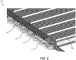
- FIG. 2 a detail view of the agricultural harvesting head 100 is depicted, according to some embodiments.
- FIG. 2 specifically depicts the portion of the harvesting head 100 containing the left side belt conveyor 104, it should be understood that the left side belt conveyor 104 and the right side belt conveyor 106 are symmetrical, and all description included below with reference to interaction of other components with the left side belt conveyor 104 is equally applicable to the right side belt conveyor 106.
- the agricultural harvesting head 100 includes multiple crop ramp segments 112. Each crop ramp segment 112 may be configured to engage with two adjacent crop ramp segments 112 such that a continuous upper crop ramp surface is provided that extends across substantially the entire width of the agricultural harvesting head 100.
- the agricultural harvesting head 100 includes a single crop ramp segment 112 that extends across substantially the entire width of the head 100.
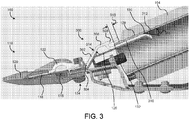
- FIG. 3 a sectional view of the agricultural harvesting head 100 is depicted, according to some embodiments.
- the agricultural harvesting head 100 includes a closed top crop ramp and belt support component 300.
- closed top component 300 is identical or substantially similar to crop ramp segment 112, described above with reference to FIGS. 1-2 .
- the reciprocating knife portion 110 of the agricultural harvesting head includes, among other components, a knife head 116, a knife back 118, a knife guard 120, and a hold down 122.
- the knife head 116 pivots relative to the knife back 118.
- the knife guard 120 protects and maintains a flat cutting surface for the knife head 116, while the hold down 122 exerts a downward force on the knife head 116 to hold the knife head 116 against the knife guard 120 and ensure a clean cutting action.
- the knife guard 120 is fastened to structural components of the harvesting head 100 at knife guard mounting point 124.
- the closed top crop ramp and belt support component 300 is shown to include a forward portion 302 that is generally planar and upwardly inclined (in a front-to-rear direction) in order to guide harvested crops for deposit onto the belt conveyor 104.
- the forward portion 302 includes a leading edge 304 that is fixed near the knife guard mounting point 124. Opposite the leading edge 304, a rear portion 306 extends from the forward portion 302.
- the rear portion 306 is generally planar and parallel to an exterior surface 128 and an interior surface 130 of the belt conveyor 104. Thus, as the forward portion 302 is inclined relative to surfaces 128 and 130, so too is the forward portion 302 inclined relative to the rear portion 306.
- the closed top component is further shown to include a belt overhang portion 308 that extends at least partially above the exterior surface 128 of the belt conveyor 104.
- Belt overhang portion 308 may act as a barrier that prevents crop losses and protects the leading edge 132 of the belt conveyor 104 from wear and impedance due to foreign object entry.
- the belt overhang portion 308 lightly contacts the exterior surface 128, although in other embodiments, a gap is maintained between the belt overhang portion 308 and the exterior surface 128.
- the region 316 that the belt overhang portion 308 extends over the exterior surface of the belt conveyor 104 ranges from 10-12 mm, although the length of region 316 may be adjusted based on the properties of the crop to be harvested.
- An additional advantage of the belt overhang portion 308 of the closed component 300 may include constraint of the belt conveyor 104.
- discontinuities in the soil e.g., rocks, foreign objects
- Movement of the reciprocating knife portion 110 may result in corresponding movement of the belt conveyor 104. This movement may be constrained as the belt conveyor 104 contacts the belt overhang portion 308 to prevent misalignment of the belt conveyor 104.
- the closed top component 300 is shown to include a belt support portion 310 that extends at least partially below the interior surface 130 of the belt conveyor 104.
- the unitary design of the closed top component 300 i.e., the lack of any gaps or joinder of parts between the forward portion 302, rear portion 306, and belt support portion 310) prevents the ingress of crop debris and other foreign materials into sensitive moving components of the agricultural head 100.
- the closed top component 300 is coupled to a structural element 126 (e.g., a weldment) that provides additional support for the belt conveyor 104.
- the belt support portion 310 terminates in a bevel portion 312 that is generally planar and inclined relative to the belt support portion 310.
- the bevel portion 312 may ease the assembly of the agricultural harvesting head 100, particularly in locating the belt support portion 310 below the interior surface 130 of the belt conveyor 104.
- the angle of inclination 318 between the belt support portion 310 and the bevel portion 312 is approximately 30 degrees.
- the closed top component 300 includes a forward portion 302 with leading edge 304, a rear portion 306, a belt overhang portion 308, a belt support portion 310, and a bevel portion 312.
- the closed top component 300 is further shown to include multiple crop ramp mounting features 320 and 322 disposed on the forward portion 302 and the belt support portion 310, respectively.
- Crop ramp mounting features 320 and 322 may be any size or shape required to accommodate the fasteners (e.g., rivets) required to attach the closed top component 300 to the structural components (e.g., weldment 126) of the agricultural harvesting head 100.
- fasteners e.g., rivets
- the agricultural harvesting head 100 includes multiple closed top components 300 that are fastened to structural components and/or each other, such that a continuous crop ramp surface is formed across the span of the agricultural harvesting head 100.
- a single closed top component 300 that extends across substantially the entire width of the head 100 may be utilized.
- FIG. 5 a sectional view of an open top crop ramp and belt support component 500 that may be utilized in the agricultural harvesting head 100 is depicted, according to some embodiments. Similar to the closed top component 300 described above with reference to FIGS. 3-4 , the open top component 500 is shown to include a generally planar forward portion 502 with a leading edge 504 that is fixed near the knife guard mounting point 124. Opposite the leading edge 504, a generally planar rear portion 506 extends from the forward portion 502, and a generally planar belt support portion 510 extends at least partially under the interior surface 130 of the belt conveyor 104. The belt support portion 510 terminates in a bevel portion 512.
- the unitary design of the open top component 500 i.e., the lack of any gaps or joinder of parts between the forward portion 502, rear portion 506, and belt support portion 510) prevents the ingress of crop debris and other foreign materials into sensitive moving components of the agricultural head 100.
- the open top component 500 does not contain a belt overhang portion to constrain the exterior surface 128 of the belt conveyor 104.
- the open top component 500 may be utilized when wear of the exterior surface 128 of the belt conveyor 104 is of particular concern.
- the unitary crop ramp and belt support component (e.g., closed top component 300, open top component 500) is fabricated from ultra-high-molecular-weight (UHMW) polyethylene using an extrusion process (e.g., ram extrusion).
- UHMW ultra-high-molecular-weight
- the wall thickness of the extrusion (e.g., wall thickness 314) is constant across the unitary component and ranges from 3-10 mm.
- the belt conveyor e.g., belt conveyor 104) may be fabricated from rubber-impregnated fabric.
- the use of UHMW for the unitary crop ramp and belt support component may be advantageous due to the material properties of UHMW, which include excellent impact strength and abrasion resistance.
- UHMW has a low coefficient of friction, which ensures smooth travel of the belt conveyor as it passes over the belt support portion (e.g., belt support portion 310, belt support portion 510) of the unitary component.
- the unitary crop ramp and belt support component may be fabricated from any suitable material (e.g., glass-filled nylon), using any suitable fabrication process (e.g., compression molding, injection molding, sintering).
Landscapes
- Life Sciences & Earth Sciences (AREA)
- Environmental Sciences (AREA)
- Harvester Elements (AREA)
- Harvesting Machines For Specific Crops (AREA)
Abstract
Description
- The present disclosure relates generally to agricultural harvesting equipment. More particularly, it relates to agricultural harvesting heads having reciprocating knives and conveyor belts, and a unitary crop ramp and belt support component for conveying crop from the reciprocating knives to the conveyor belts.
- Grain harvesting operations for crops such as wheat, soybeans, and rice are often completed by agricultural machines that include multiple reciprocating knives at the leading edge of the machine. The reciprocating knives sever the crop plants at their roots, permitting the harvested crops to fall onto one or more conveyor belts. Typically, a crop ramp is provided that ensures that harvested crop material is effectively conveyed to an exterior surface of a conveyor belt.
- Harvesting operations generally create a significant amount of crop residue that must be controlled lest it become lodged in critical areas and interfere with the movement of a conveyor belt. In severe cases, buildup may premature wear or stall of a conveyor belt. A crop ramp component design that supports and protects the conveyor belt, prevents the ingress of foreign objects into the agricultural harvesting head, and helps seal against crop losses would therefore be useful.
- In accordance with one aspect of the invention, a crop ramp and belt support component for an agricultural harvesting head is provided. The crop ramp and belt support component includes a forward portion, a rear portion, and a belt support portion that are generally planar. The forward portion is inclined relative to the rear portion, and the rear portion extends from the forward portion. The belt support portion is substantially parallel to the rear portion and is configured to extend at least partially below an interior surface of a belt conveyor. The forward portion, the rear portion, and the belt support portion are fabricated as a unitary component.
- The unitary component may be fabricated from ultra-high-molecular-weight polyethylene. The unitary component may be fabricated using an extrusion process. The unitary component may have a substantially constant extruded wall thickness. The extruded wall thickness may range from 3 mm to 10 mm.
- The crop ramp and belt support component may include a belt overhang portion that is generally planar and configured to extend at least partially above an exterior surface of the belt conveyor. The belt overhang portion may be substantially parallel to the belt support portion. The region that the belt overhang portion overlaps the exterior surface of the belt conveyor may range from 10 mm to 12 mm. The crop ramp and belt support component may include a bevel portion that is generally planar and inclined relative to the belt support portion. The angle of inclination between the belt support portion and the bevel portion may be approximately 30 degrees.
- In accordance with another aspect of the invention, an agricultural harvesting head is provided. The agricultural harvesting head includes a frame that extends laterally, a reciprocating knife that is supported on the frame, a belt conveyor that is supported on the frame and driven in a lateral direction, and a crop ramp and belt support component. The crop ramp and belt support component includes a forward portion, a rear portion, and a belt support portion that are generally planar. The forward portion is inclined relative to the rear portion, and the rear portion extends from the forward portion. The belt support portion is substantially parallel to the rear portion and is configured to extend at least partially below an interior surface of a belt conveyor. The forward portion, the rear portion, and the belt support portion are fabricated as a unitary component.
- The crop ramp and belt support component may include a belt overhang portion that is generally planar and configured to extend at least partially above an exterior surface of the belt conveyor. The belt overhang portion may be substantially parallel to the belt support portion. The region that the belt overhang portion overlaps the exterior surface of the belt conveyor may range from 10 mm to 12 mm. The crop ramp and belt support component may include a bevel portion that is generally planar and inclined relative to the belt support portion. The angle of inclination between the belt support portion and the bevel portion may be approximately 30 degrees.
- In accordance with yet another aspect of the invention, a method of fabricating a crop ramp and belt support component for an agricultural harvesting head is provided. The method includes providing a forward portion that is generally planar, providing a rear portion that is generally planar and that extends from the forward portion, the forward portion inclined relative to the rear portion, and providing a belt support portion that is generally planar and substantially parallel to the rear portion. The belt support portion is configured to extend at least partially below an interior surface of a belt conveyor and the forward portion, the rear portion, and the belt support portion form a unitary component.
- The method may include providing a belt overhang portion that is generally planar and configured to extend at least partially above an exterior surface of the belt conveyor. The belt overhang portion may be substantially parallel to the belt support portion. The method may include providing a bevel portion that is generally planar and inclined relative to the belt support portion. The angle of inclination between the belt support portion and the bevel portion may be approximately 30 degrees.
-
-
FIG. 1 is a perspective view of an agricultural harvesting head, according to some embodiments. -
FIG. 2 is a detail view of the agricultural harvesting head ofFIG. 1 , according to some embodiments. -
FIG. 3 is a sectional view of the agricultural harvesting head ofFIG. 1 depicting a closed top crop ramp and belt support component, according to some embodiments. -
FIG. 4 is a perspective view of the closed top crop ramp and belt support component ofFIG. 3 , according to some embodiments. -
FIG. 5 is a sectional view of the agricultural harvesting head ofFIG. 1 depicting an open top crop ramp and belt support component, according to some embodiments. - Referring generally to the FIGURES, a unitary crop ramp and belt support component is depicted, according to various embodiments. One or more conveyor belts are often utilized to transfer harvested crops from a cutting implement to a collecting device (e.g., an agricultural combine). A crop ramp is situated between the cutting implement and the conveyor belts to provide a smooth path of travel for the crops. The unitary design of the crop ramp and belt support of the present disclosure helps seal against crop losses, prevents ingress of foreign objects into critical moving parts, and protects the belt against excessive wear.
- Referring now to
FIG. 1 , anagricultural harvesting head 100 is depicted, according to some embodiments. Theagricultural harvesting head 100 includes aframe 102 that extends laterally across substantially the entire width of thehead 100. Theframe 102 is configured to support a leftside belt conveyor 104, a rightside belt conveyor 106, acenter belt conveyor 108, a reciprocatingknife portion 110, multiplecrop ramp segments 112, and afeed drum 114. - As the
agricultural harvesting head 100 travels in the direction indicated by the arrow labeled "V", the reciprocatingknives 110 are configured to sever crop plants at their roots, thereby freeing them from the soil. Once severed, thecrop ramp segments 112 direct the crops upward and rearward until they alternatively fall onto the leftside belt conveyor 104, the rightside belt conveyor 106, or thecenter belt conveyor 108. - Each of the left
side belt conveyor 104, the rightside belt conveyor 106, and thecenter belt conveyor 108 is driven by motors (not shown) and supported on rollers (not shown). The leftside belt conveyor 104 and the rightside belt conveyor 106 are similarly configured to carry harvested crops laterally on an upper surface of thebelt conveyors center belt conveyor 108. - The
center belt conveyor 108 is configured to carry harvested crops deposited on an upper surface of thebelt conveyor 108 rearward and underneath thefeed drum 114. In some embodiments, theagricultural harvesting head 100 is supported on a feederhouse (not shown) on the front of an agricultural combine. The feederhouse is configured to receive harvested crop material that passes underneath thefeed drum 114 and to transmit the harvested crop material into the agricultural combine for further processing and storage. - Referring now to
FIG. 2 , a detail view of theagricultural harvesting head 100 is depicted, according to some embodiments. AlthoughFIG. 2 specifically depicts the portion of theharvesting head 100 containing the leftside belt conveyor 104, it should be understood that the leftside belt conveyor 104 and the rightside belt conveyor 106 are symmetrical, and all description included below with reference to interaction of other components with the leftside belt conveyor 104 is equally applicable to the rightside belt conveyor 106. As shown, in some embodiments, theagricultural harvesting head 100 includes multiplecrop ramp segments 112. Eachcrop ramp segment 112 may be configured to engage with two adjacentcrop ramp segments 112 such that a continuous upper crop ramp surface is provided that extends across substantially the entire width of theagricultural harvesting head 100. In other embodiments, theagricultural harvesting head 100 includes a singlecrop ramp segment 112 that extends across substantially the entire width of thehead 100. - Turning now to
FIG. 3 , a sectional view of theagricultural harvesting head 100 is depicted, according to some embodiments. As shown, in addition to the components described above (i.e., reciprocatingknife portion 110, belt conveyor 104), theagricultural harvesting head 100 includes a closed top crop ramp andbelt support component 300. In some embodiments, closedtop component 300 is identical or substantially similar tocrop ramp segment 112, described above with reference toFIGS. 1-2 . - The
reciprocating knife portion 110 of the agricultural harvesting head includes, among other components, aknife head 116, a knife back 118, aknife guard 120, and a hold down 122. In operation, theknife head 116 pivots relative to the knife back 118. Theknife guard 120 protects and maintains a flat cutting surface for theknife head 116, while the hold down 122 exerts a downward force on theknife head 116 to hold theknife head 116 against theknife guard 120 and ensure a clean cutting action. Theknife guard 120 is fastened to structural components of theharvesting head 100 at knifeguard mounting point 124. - The closed top crop ramp and
belt support component 300 is shown to include aforward portion 302 that is generally planar and upwardly inclined (in a front-to-rear direction) in order to guide harvested crops for deposit onto thebelt conveyor 104. Theforward portion 302 includes aleading edge 304 that is fixed near the knifeguard mounting point 124. Opposite theleading edge 304, arear portion 306 extends from theforward portion 302. Therear portion 306 is generally planar and parallel to anexterior surface 128 and aninterior surface 130 of thebelt conveyor 104. Thus, as theforward portion 302 is inclined relative tosurfaces forward portion 302 inclined relative to therear portion 306. - The closed top component is further shown to include a
belt overhang portion 308 that extends at least partially above theexterior surface 128 of thebelt conveyor 104.Belt overhang portion 308 may act as a barrier that prevents crop losses and protects theleading edge 132 of thebelt conveyor 104 from wear and impedance due to foreign object entry. In some embodiments, thebelt overhang portion 308 lightly contacts theexterior surface 128, although in other embodiments, a gap is maintained between thebelt overhang portion 308 and theexterior surface 128. In some embodiments, theregion 316 that thebelt overhang portion 308 extends over the exterior surface of thebelt conveyor 104 ranges from 10-12 mm, although the length ofregion 316 may be adjusted based on the properties of the crop to be harvested. - An additional advantage of the
belt overhang portion 308 of theclosed component 300 may include constraint of thebelt conveyor 104. As theagricultural harvesting head 100 is configured to travel as near to the ground in order to harvest as much usable crop as possible, discontinuities in the soil (e.g., rocks, foreign objects) may cause thereciprocating knife portion 110 to flex in a vertical direction. Movement of thereciprocating knife portion 110 may result in corresponding movement of thebelt conveyor 104. This movement may be constrained as thebelt conveyor 104 contacts thebelt overhang portion 308 to prevent misalignment of thebelt conveyor 104. - Still referring to
FIG. 3 , the closedtop component 300 is shown to include abelt support portion 310 that extends at least partially below theinterior surface 130 of thebelt conveyor 104. The unitary design of the closed top component 300 (i.e., the lack of any gaps or joinder of parts between theforward portion 302,rear portion 306, and belt support portion 310) prevents the ingress of crop debris and other foreign materials into sensitive moving components of theagricultural head 100. In some embodiments, the closedtop component 300 is coupled to a structural element 126 (e.g., a weldment) that provides additional support for thebelt conveyor 104. Thebelt support portion 310 terminates in abevel portion 312 that is generally planar and inclined relative to thebelt support portion 310. Thebevel portion 312 may ease the assembly of theagricultural harvesting head 100, particularly in locating thebelt support portion 310 below theinterior surface 130 of thebelt conveyor 104. In some embodiments, the angle of inclination 318 between thebelt support portion 310 and thebevel portion 312 is approximately 30 degrees. - Referring now to
FIG. 4 , a perspective view of an isolated closed top crop ramp andbelt support component 300 is shown, according to some embodiments. As described above with reference toFIG. 3 , the closedtop component 300 includes aforward portion 302 withleading edge 304, arear portion 306, abelt overhang portion 308, abelt support portion 310, and abevel portion 312. The closedtop component 300 is further shown to include multiple cropramp mounting features forward portion 302 and thebelt support portion 310, respectively. Crop ramp mounting features 320 and 322 may be any size or shape required to accommodate the fasteners (e.g., rivets) required to attach the closedtop component 300 to the structural components (e.g., weldment 126) of theagricultural harvesting head 100. - In some embodiments, the
agricultural harvesting head 100 includes multiple closedtop components 300 that are fastened to structural components and/or each other, such that a continuous crop ramp surface is formed across the span of theagricultural harvesting head 100. In other embodiments, a single closedtop component 300 that extends across substantially the entire width of thehead 100 may be utilized. - Referring now to
FIG. 5 , a sectional view of an open top crop ramp andbelt support component 500 that may be utilized in theagricultural harvesting head 100 is depicted, according to some embodiments. Similar to the closedtop component 300 described above with reference toFIGS. 3-4 , the opentop component 500 is shown to include a generally planarforward portion 502 with aleading edge 504 that is fixed near the knifeguard mounting point 124. Opposite theleading edge 504, a generally planarrear portion 506 extends from theforward portion 502, and a generally planarbelt support portion 510 extends at least partially under theinterior surface 130 of thebelt conveyor 104. Thebelt support portion 510 terminates in abevel portion 512. The unitary design of the open top component 500 (i.e., the lack of any gaps or joinder of parts between theforward portion 502,rear portion 506, and belt support portion 510) prevents the ingress of crop debris and other foreign materials into sensitive moving components of theagricultural head 100. However, in contrast to the closedtop component 300, the opentop component 500 does not contain a belt overhang portion to constrain theexterior surface 128 of thebelt conveyor 104. The opentop component 500 may be utilized when wear of theexterior surface 128 of thebelt conveyor 104 is of particular concern. - In some embodiments, the unitary crop ramp and belt support component (e.g., closed
top component 300, open top component 500) is fabricated from ultra-high-molecular-weight (UHMW) polyethylene using an extrusion process (e.g., ram extrusion). In various embodiments, the wall thickness of the extrusion (e.g., wall thickness 314) is constant across the unitary component and ranges from 3-10 mm. The belt conveyor (e.g., belt conveyor 104) may be fabricated from rubber-impregnated fabric. The use of UHMW for the unitary crop ramp and belt support component may be advantageous due to the material properties of UHMW, which include excellent impact strength and abrasion resistance. In addition, UHMW has a low coefficient of friction, which ensures smooth travel of the belt conveyor as it passes over the belt support portion (e.g.,belt support portion 310, belt support portion 510) of the unitary component. However, in other embodiments, the unitary crop ramp and belt support component may be fabricated from any suitable material (e.g., glass-filled nylon), using any suitable fabrication process (e.g., compression molding, injection molding, sintering). - It should be understood that the particular embodiments shown and discussed herein are not the only ways in which the invention can exist. They are the currently preferred embodiments of the invention. One skilled in the art of agricultural harvester and agricultural harvesting head design and manufacture can readily see other variations that would also fall within the scope of the appended claims.
Claims (15)
- A crop ramp and belt support component for an agricultural harvesting head, the crop ramp and belt support component comprising:a forward portion that is generally planar;a rear portion that is generally planar and that extends from the forward portion, the forward portion inclined relative to the rear portion; anda belt support portion that is generally planar and substantially parallel to the rear portion, the belt support portion configured to extend at least partially below an interior surface of a belt conveyor;wherein the forward portion, the rear portion, and the belt support portion are fabricated as a unitary component.
- The crop ramp and belt support component of claim 1, wherein the unitary component is fabricated from ultra-high-molecular-weight polyethylene.
- The crop ramp and belt support component of claim 1, wherein the unitary component is fabricated using an extrusion process.
- The crop ramp and belt support component of claim 3, wherein the unitary component has a substantially constant extruded wall thickness.
- The crop ramp and belt support component of claim 4, wherein the extruded wall thickness ranges from 3 mm to 10 mm.
- The crop ramp and belt support component of claim 1, further comprising a belt overhang portion that is generally planar and configured to extend at least partially above an exterior surface of the belt conveyor.
- The crop ramp and belt support component of claim 6, wherein the belt overhang portion is substantially parallel to the belt support portion.
- The crop ramp and belt support component of claim 6, wherein a region that the belt overhang portion overlaps the exterior surface of the belt conveyor ranges from 10 mm to 12 mm.
- The crop ramp and belt support component of claim 1, further comprising a bevel portion that is generally planar and inclined relative to the belt support portion.
- The crop ramp and belt support component of claim 9, wherein an angle of inclination between the belt support portion and the bevel portion is approximately 30 degrees.
- An agricultural harvesting head comprising:a frame that extends laterally;a reciprocating knife that is supported on the frame;a belt conveyor that is supported on the frame and driven in a lateral direction; anda crop ramp and belt support component comprising:a forward portion that is generally planar;a rear portion that is generally planar and that extends from the forward portion, the forward portion inclined relative to the rear portion; anda belt support portion that is generally planar and substantially parallel to the rear portion, the belt support portion configured to extend at least partially below an interior surface of the belt conveyor;wherein the forward portion, the rear portion, and the belt support portion are fabricated as a unitary component.
- The agricultural harvesting head of claim 11, wherein the crop ramp and belt support component further comprises a belt overhang portion that is generally planar and configured to extend at least partially above an exterior surface of the belt conveyor.
- The agricultural harvesting head of claim 12, wherein the belt overhang portion is substantially parallel to the belt support portion.
- The agricultural harvesting head of claim 13, wherein a region that the belt overhang portion overlaps the exterior surface of the belt conveyor ranges from 10 mm to 12 mm.
- The agricultural harvesting head of claim 11, wherein the crop ramp and belt support component further comprises a bevel portion that is generally planar and inclined at an angle relative to the belt support portion of approximately 30 degrees.
Applications Claiming Priority (1)
| Application Number | Priority Date | Filing Date | Title |
|---|---|---|---|
| US16/005,475 US10813290B2 (en) | 2018-06-11 | 2018-06-11 | Component and method for crop ramp and belt support |
Publications (2)
| Publication Number | Publication Date |
|---|---|
| EP3581015A1 true EP3581015A1 (en) | 2019-12-18 |
| EP3581015B1 EP3581015B1 (en) | 2022-08-10 |
Family
ID=66793856
Family Applications (1)
| Application Number | Title | Priority Date | Filing Date |
|---|---|---|---|
| EP19179043.5A Active EP3581015B1 (en) | 2018-06-11 | 2019-06-07 | Unitary component crop ramp and belt support |
Country Status (4)
| Country | Link |
|---|---|
| US (1) | US10813290B2 (en) |
| EP (1) | EP3581015B1 (en) |
| BR (1) | BR102019008073B1 (en) |
| CA (1) | CA3039415A1 (en) |
Cited By (1)
| Publication number | Priority date | Publication date | Assignee | Title |
|---|---|---|---|---|
| WO2021097196A1 (en) * | 2019-11-13 | 2021-05-20 | Cnh Industrial America Llc | Draper belt assembly for an agricultural harvester and header comprising the same |
Families Citing this family (8)
| Publication number | Priority date | Publication date | Assignee | Title |
|---|---|---|---|---|
| US11589512B2 (en) * | 2017-07-25 | 2023-02-28 | Cnh Industrial America Llc | Draper support for a draper belt assembly of an agricultural harvester |
| BR102018073067B1 (en) * | 2018-11-09 | 2024-02-27 | Agrisoltec - Soluções Tecnológicas Para Agricultura Ltda | FLEXIBLE FRONT RAMP FOR RIGID AND FLEXIBLE CUTTING DECK |
| WO2020101993A1 (en) * | 2018-11-16 | 2020-05-22 | Cnh Industrial America Llc | Harvester header with lateral belt roller mount |
| EP3659425B1 (en) * | 2018-11-27 | 2024-05-01 | CNH Industrial Belgium N.V. | Header for an agricultural harvester having a draper conveyor seal |
| US11617305B2 (en) * | 2020-05-21 | 2023-04-04 | Cnh Industrial America Llc | Crop ramps for combine headers |
| AR123561A1 (en) * | 2020-09-28 | 2022-12-14 | Cnh Ind America Llc | HEAD FOR AN AGRICULTURAL COMBINE HAVING AN INTEGRATED SEED SAVER |
| US12550823B2 (en) | 2022-06-15 | 2026-02-17 | Cnh Industrial America Llc | Agricultural header with a draper belt including a seed saver disposed behind one or more crop ramps |
| EP4656033A1 (en) | 2024-05-27 | 2025-12-03 | Dominoni S.r.L | Conveying device |
Citations (4)
| Publication number | Priority date | Publication date | Assignee | Title |
|---|---|---|---|---|
| EP1867228A1 (en) * | 2006-06-14 | 2007-12-19 | Deere & Company | Reel height control for a flexible cutting platform in an agricultural harvesting machine |
| US7958711B1 (en) * | 2010-06-16 | 2011-06-14 | Agco Corporation | Crop deflector for ends of draper belt of flexible draper header |
| WO2014032178A1 (en) * | 2012-08-31 | 2014-03-06 | Macdon Industries Ltd. | Draper support of a crop harvesting header |
| US20160316620A1 (en) * | 2015-04-28 | 2016-11-03 | Jose Luis Allochis | Belt sealing crop deflector for a flexible draper platform |
Family Cites Families (22)
| Publication number | Priority date | Publication date | Assignee | Title |
|---|---|---|---|---|
| US1917604A (en) * | 1931-04-30 | 1933-07-11 | Avery Power Machinery Co | Sickle guard and shield |
| US5161355A (en) | 1991-03-06 | 1992-11-10 | Ford New Holland Inc. | Filler ramp for forage harvester row crop attachments |
| US5459986A (en) * | 1994-12-27 | 1995-10-24 | Macdon Industries Ltd. | Draper header with canvas to cutter bar seal |
| US6351931B1 (en) | 2000-06-09 | 2002-03-05 | Macdon Industries Ltd. | Crop header with draper canvas |
| US7549280B2 (en) * | 2006-03-02 | 2009-06-23 | Deere & Company | Sectionalized belt guide for draper belt in an agricultural harvesting machine |
| US7412816B2 (en) * | 2006-03-02 | 2008-08-19 | Deere & Company | Sectionalized belt guide for draper belt in an agricultural harvesting machine |
| US7600364B2 (en) * | 2006-03-02 | 2009-10-13 | Deere & Company | Sectionalized belt guide for draper belt in an agricultural harvesting machine |
| CA2564777C (en) * | 2006-10-20 | 2010-08-03 | Macdon Industries Ltd. | Crop header with draper canvas and a seal with an element of the cutter bar |
| US20090266044A1 (en) * | 2008-04-25 | 2009-10-29 | Coers Bruce A | Integrated draper belt support and skid shoe in an agricultural harvesting machine |
| US8205421B2 (en) * | 2010-06-16 | 2012-06-26 | Agco Corporation | Belt guard crop dam for flexible draper header |
| US7908836B1 (en) * | 2010-07-20 | 2011-03-22 | Cnh America Llc | Draper header with multiple sided cut crop barrier interface between the cutter bar and draper canvas |
| US8322520B2 (en) * | 2010-08-17 | 2012-12-04 | Deere & Company | Tongue-in-groove belt hold down for a draper platform |
| CA2734475C (en) * | 2011-03-16 | 2012-10-09 | Macdon Industries Ltd. | Drive roller for the draper canvas of a crop header |
| US8291686B1 (en) * | 2011-06-17 | 2012-10-23 | Macdon Industries Ltd | Draper canvas with a shaped edge |
| US8479483B1 (en) * | 2011-12-27 | 2013-07-09 | Agco Corporation | Flexible draper head providing reduced crop residue accumulation |
| EP2797403B1 (en) * | 2011-12-28 | 2016-11-30 | Agco Corporation | Skid plate for crop header having flexible cutterbar |
| US8511050B1 (en) * | 2012-08-31 | 2013-08-20 | Macdon Industries Ltd. | Draper support of a crop harvesting header |
| US8484939B1 (en) * | 2012-08-31 | 2013-07-16 | Macdon Industries Ltd. | Draper seal for crop harvesting header |
| CA2799093A1 (en) * | 2012-12-18 | 2014-06-18 | Honey Bee Manufacturing Ltd. | Draper seal for crop header |
| DE102013100322A1 (en) * | 2013-01-14 | 2014-07-17 | Claas Selbstfahrende Erntemaschinen Gmbh | cutting |
| US9338941B2 (en) * | 2013-07-02 | 2016-05-17 | Deere & Company | Self clearing crop ramp |
| US10462968B2 (en) * | 2016-11-24 | 2019-11-05 | Macdon Industries Ltd. | Header with flexible crop cutting knife |
-
2018
- 2018-06-11 US US16/005,475 patent/US10813290B2/en active Active
-
2019
- 2019-04-08 CA CA3039415A patent/CA3039415A1/en active Pending
- 2019-04-18 BR BR102019008073-6A patent/BR102019008073B1/en active IP Right Grant
- 2019-06-07 EP EP19179043.5A patent/EP3581015B1/en active Active
Patent Citations (4)
| Publication number | Priority date | Publication date | Assignee | Title |
|---|---|---|---|---|
| EP1867228A1 (en) * | 2006-06-14 | 2007-12-19 | Deere & Company | Reel height control for a flexible cutting platform in an agricultural harvesting machine |
| US7958711B1 (en) * | 2010-06-16 | 2011-06-14 | Agco Corporation | Crop deflector for ends of draper belt of flexible draper header |
| WO2014032178A1 (en) * | 2012-08-31 | 2014-03-06 | Macdon Industries Ltd. | Draper support of a crop harvesting header |
| US20160316620A1 (en) * | 2015-04-28 | 2016-11-03 | Jose Luis Allochis | Belt sealing crop deflector for a flexible draper platform |
Cited By (2)
| Publication number | Priority date | Publication date | Assignee | Title |
|---|---|---|---|---|
| WO2021097196A1 (en) * | 2019-11-13 | 2021-05-20 | Cnh Industrial America Llc | Draper belt assembly for an agricultural harvester and header comprising the same |
| US11297770B2 (en) | 2019-11-13 | 2022-04-12 | Cnh Industrial America Llc | Draper belt assembly for an agricultural harvester |
Also Published As
| Publication number | Publication date |
|---|---|
| BR102019008073B1 (en) | 2024-03-12 |
| CA3039415A1 (en) | 2019-12-11 |
| US10813290B2 (en) | 2020-10-27 |
| EP3581015B1 (en) | 2022-08-10 |
| US20190373815A1 (en) | 2019-12-12 |
| BR102019008073A2 (en) | 2019-12-24 |
Similar Documents
| Publication | Publication Date | Title |
|---|---|---|
| EP3581015B1 (en) | Unitary component crop ramp and belt support | |
| USRE50592E1 (en) | Draper seal for crop header | |
| US7908836B1 (en) | Draper header with multiple sided cut crop barrier interface between the cutter bar and draper canvas | |
| US9144197B2 (en) | Dual conveyor infeed for a header of an agricultural harvester | |
| US6658832B2 (en) | Crop deflector for machine for mowing stalk-like crops | |
| US9338941B2 (en) | Self clearing crop ramp | |
| US9220198B2 (en) | Header with drivable crop conveying elements | |
| EP3659425B1 (en) | Header for an agricultural harvester having a draper conveyor seal | |
| EP3476200B1 (en) | Draper belt roller support and harvester header comprising roller support | |
| US20140237978A1 (en) | Frusto-conical conveyor with retracting fingers | |
| US9179601B2 (en) | Corn head assembly with catch plate | |
| US11399458B2 (en) | Agricultural header with debris removal system | |
| US9538707B2 (en) | Harvester header with belt length adapting mechanism | |
| CN113068508B (en) | Grain loss prevention system using blower | |
| US20220007583A1 (en) | Flexible front ramp for rigid and flexible cutting platform | |
| US4324092A (en) | Cutterbar wear strip | |
| JP4104118B2 (en) | Combine pre-processing unit structure | |
| JPH09163857A (en) | Glen tank | |
| JP2020065473A (en) | Combine | |
| CN112823583A (en) | Loss capture and recirculation system for a belted header | |
| JPH06153662A (en) | Combine harvester culm carrier | |
| JPH11332343A (en) | Root vegetable harvester | |
| UA46811C2 (en) | ROOT TUBER HARVESTER |
Legal Events
| Date | Code | Title | Description |
|---|---|---|---|
| PUAI | Public reference made under article 153(3) epc to a published international application that has entered the european phase |
Free format text: ORIGINAL CODE: 0009012 |
|
| STAA | Information on the status of an ep patent application or granted ep patent |
Free format text: STATUS: THE APPLICATION HAS BEEN PUBLISHED |
|
| AK | Designated contracting states |
Kind code of ref document: A1 Designated state(s): AL AT BE BG CH CY CZ DE DK EE ES FI FR GB GR HR HU IE IS IT LI LT LU LV MC MK MT NL NO PL PT RO RS SE SI SK SM TR |
|
| AX | Request for extension of the european patent |
Extension state: BA ME |
|
| STAA | Information on the status of an ep patent application or granted ep patent |
Free format text: STATUS: REQUEST FOR EXAMINATION WAS MADE |
|
| 17P | Request for examination filed |
Effective date: 20200618 |
|
| RBV | Designated contracting states (corrected) |
Designated state(s): AL AT BE BG CH CY CZ DE DK EE ES FI FR GB GR HR HU IE IS IT LI LT LU LV MC MK MT NL NO PL PT RO RS SE SI SK SM TR |
|
| GRAP | Despatch of communication of intention to grant a patent |
Free format text: ORIGINAL CODE: EPIDOSNIGR1 |
|
| STAA | Information on the status of an ep patent application or granted ep patent |
Free format text: STATUS: GRANT OF PATENT IS INTENDED |
|
| INTG | Intention to grant announced |
Effective date: 20220322 |
|
| GRAS | Grant fee paid |
Free format text: ORIGINAL CODE: EPIDOSNIGR3 |
|
| GRAA | (expected) grant |
Free format text: ORIGINAL CODE: 0009210 |
|
| STAA | Information on the status of an ep patent application or granted ep patent |
Free format text: STATUS: THE PATENT HAS BEEN GRANTED |
|
| AK | Designated contracting states |
Kind code of ref document: B1 Designated state(s): AL AT BE BG CH CY CZ DE DK EE ES FI FR GB GR HR HU IE IS IT LI LT LU LV MC MK MT NL NO PL PT RO RS SE SI SK SM TR |
|
| REG | Reference to a national code |
Ref country code: AT Ref legal event code: REF Ref document number: 1509826 Country of ref document: AT Kind code of ref document: T Effective date: 20220815 Ref country code: CH Ref legal event code: EP |
|
| REG | Reference to a national code |
Ref country code: IE Ref legal event code: FG4D |
|
| REG | Reference to a national code |
Ref country code: DE Ref legal event code: R096 Ref document number: 602019017982 Country of ref document: DE |
|
| REG | Reference to a national code |
Ref country code: NL Ref legal event code: MP Effective date: 20220810 |
|
| REG | Reference to a national code |
Ref country code: LT Ref legal event code: MG9D |
|
| PG25 | Lapsed in a contracting state [announced via postgrant information from national office to epo] |
Ref country code: SE Free format text: LAPSE BECAUSE OF FAILURE TO SUBMIT A TRANSLATION OF THE DESCRIPTION OR TO PAY THE FEE WITHIN THE PRESCRIBED TIME-LIMIT Effective date: 20220810 Ref country code: RS Free format text: LAPSE BECAUSE OF FAILURE TO SUBMIT A TRANSLATION OF THE DESCRIPTION OR TO PAY THE FEE WITHIN THE PRESCRIBED TIME-LIMIT Effective date: 20220810 Ref country code: PT Free format text: LAPSE BECAUSE OF FAILURE TO SUBMIT A TRANSLATION OF THE DESCRIPTION OR TO PAY THE FEE WITHIN THE PRESCRIBED TIME-LIMIT Effective date: 20221212 Ref country code: NO Free format text: LAPSE BECAUSE OF FAILURE TO SUBMIT A TRANSLATION OF THE DESCRIPTION OR TO PAY THE FEE WITHIN THE PRESCRIBED TIME-LIMIT Effective date: 20221110 Ref country code: NL Free format text: LAPSE BECAUSE OF FAILURE TO SUBMIT A TRANSLATION OF THE DESCRIPTION OR TO PAY THE FEE WITHIN THE PRESCRIBED TIME-LIMIT Effective date: 20220810 Ref country code: LV Free format text: LAPSE BECAUSE OF FAILURE TO SUBMIT A TRANSLATION OF THE DESCRIPTION OR TO PAY THE FEE WITHIN THE PRESCRIBED TIME-LIMIT Effective date: 20220810 Ref country code: LT Free format text: LAPSE BECAUSE OF FAILURE TO SUBMIT A TRANSLATION OF THE DESCRIPTION OR TO PAY THE FEE WITHIN THE PRESCRIBED TIME-LIMIT Effective date: 20220810 Ref country code: FI Free format text: LAPSE BECAUSE OF FAILURE TO SUBMIT A TRANSLATION OF THE DESCRIPTION OR TO PAY THE FEE WITHIN THE PRESCRIBED TIME-LIMIT Effective date: 20220810 |
|
| REG | Reference to a national code |
Ref country code: AT Ref legal event code: MK05 Ref document number: 1509826 Country of ref document: AT Kind code of ref document: T Effective date: 20220810 |
|
| PG25 | Lapsed in a contracting state [announced via postgrant information from national office to epo] |
Ref country code: PL Free format text: LAPSE BECAUSE OF FAILURE TO SUBMIT A TRANSLATION OF THE DESCRIPTION OR TO PAY THE FEE WITHIN THE PRESCRIBED TIME-LIMIT Effective date: 20220810 Ref country code: IS Free format text: LAPSE BECAUSE OF FAILURE TO SUBMIT A TRANSLATION OF THE DESCRIPTION OR TO PAY THE FEE WITHIN THE PRESCRIBED TIME-LIMIT Effective date: 20221210 Ref country code: HR Free format text: LAPSE BECAUSE OF FAILURE TO SUBMIT A TRANSLATION OF THE DESCRIPTION OR TO PAY THE FEE WITHIN THE PRESCRIBED TIME-LIMIT Effective date: 20220810 Ref country code: GR Free format text: LAPSE BECAUSE OF FAILURE TO SUBMIT A TRANSLATION OF THE DESCRIPTION OR TO PAY THE FEE WITHIN THE PRESCRIBED TIME-LIMIT Effective date: 20221111 |
|
| PG25 | Lapsed in a contracting state [announced via postgrant information from national office to epo] |
Ref country code: SM Free format text: LAPSE BECAUSE OF FAILURE TO SUBMIT A TRANSLATION OF THE DESCRIPTION OR TO PAY THE FEE WITHIN THE PRESCRIBED TIME-LIMIT Effective date: 20220810 Ref country code: RO Free format text: LAPSE BECAUSE OF FAILURE TO SUBMIT A TRANSLATION OF THE DESCRIPTION OR TO PAY THE FEE WITHIN THE PRESCRIBED TIME-LIMIT Effective date: 20220810 Ref country code: ES Free format text: LAPSE BECAUSE OF FAILURE TO SUBMIT A TRANSLATION OF THE DESCRIPTION OR TO PAY THE FEE WITHIN THE PRESCRIBED TIME-LIMIT Effective date: 20220810 Ref country code: DK Free format text: LAPSE BECAUSE OF FAILURE TO SUBMIT A TRANSLATION OF THE DESCRIPTION OR TO PAY THE FEE WITHIN THE PRESCRIBED TIME-LIMIT Effective date: 20220810 Ref country code: CZ Free format text: LAPSE BECAUSE OF FAILURE TO SUBMIT A TRANSLATION OF THE DESCRIPTION OR TO PAY THE FEE WITHIN THE PRESCRIBED TIME-LIMIT Effective date: 20220810 Ref country code: AT Free format text: LAPSE BECAUSE OF FAILURE TO SUBMIT A TRANSLATION OF THE DESCRIPTION OR TO PAY THE FEE WITHIN THE PRESCRIBED TIME-LIMIT Effective date: 20220810 |
|
| REG | Reference to a national code |
Ref country code: DE Ref legal event code: R097 Ref document number: 602019017982 Country of ref document: DE |
|
| PG25 | Lapsed in a contracting state [announced via postgrant information from national office to epo] |
Ref country code: SK Free format text: LAPSE BECAUSE OF FAILURE TO SUBMIT A TRANSLATION OF THE DESCRIPTION OR TO PAY THE FEE WITHIN THE PRESCRIBED TIME-LIMIT Effective date: 20220810 Ref country code: EE Free format text: LAPSE BECAUSE OF FAILURE TO SUBMIT A TRANSLATION OF THE DESCRIPTION OR TO PAY THE FEE WITHIN THE PRESCRIBED TIME-LIMIT Effective date: 20220810 |
|
| PLBE | No opposition filed within time limit |
Free format text: ORIGINAL CODE: 0009261 |
|
| STAA | Information on the status of an ep patent application or granted ep patent |
Free format text: STATUS: NO OPPOSITION FILED WITHIN TIME LIMIT |
|
| PG25 | Lapsed in a contracting state [announced via postgrant information from national office to epo] |
Ref country code: AL Free format text: LAPSE BECAUSE OF FAILURE TO SUBMIT A TRANSLATION OF THE DESCRIPTION OR TO PAY THE FEE WITHIN THE PRESCRIBED TIME-LIMIT Effective date: 20220810 |
|
| 26N | No opposition filed |
Effective date: 20230511 |
|
| PG25 | Lapsed in a contracting state [announced via postgrant information from national office to epo] |
Ref country code: SI Free format text: LAPSE BECAUSE OF FAILURE TO SUBMIT A TRANSLATION OF THE DESCRIPTION OR TO PAY THE FEE WITHIN THE PRESCRIBED TIME-LIMIT Effective date: 20220810 |
|
| PG25 | Lapsed in a contracting state [announced via postgrant information from national office to epo] |
Ref country code: MC Free format text: LAPSE BECAUSE OF FAILURE TO SUBMIT A TRANSLATION OF THE DESCRIPTION OR TO PAY THE FEE WITHIN THE PRESCRIBED TIME-LIMIT Effective date: 20220810 |
|
| PG25 | Lapsed in a contracting state [announced via postgrant information from national office to epo] |
Ref country code: MC Free format text: LAPSE BECAUSE OF FAILURE TO SUBMIT A TRANSLATION OF THE DESCRIPTION OR TO PAY THE FEE WITHIN THE PRESCRIBED TIME-LIMIT Effective date: 20220810 |
|
| REG | Reference to a national code |
Ref country code: CH Ref legal event code: PL |
|
| REG | Reference to a national code |
Ref country code: BE Ref legal event code: MM Effective date: 20230630 |
|
| GBPC | Gb: european patent ceased through non-payment of renewal fee |
Effective date: 20230607 |
|
| PG25 | Lapsed in a contracting state [announced via postgrant information from national office to epo] |
Ref country code: LU Free format text: LAPSE BECAUSE OF NON-PAYMENT OF DUE FEES Effective date: 20230607 |
|
| REG | Reference to a national code |
Ref country code: IE Ref legal event code: MM4A |
|
| PG25 | Lapsed in a contracting state [announced via postgrant information from national office to epo] |
Ref country code: LU Free format text: LAPSE BECAUSE OF NON-PAYMENT OF DUE FEES Effective date: 20230607 |
|
| PG25 | Lapsed in a contracting state [announced via postgrant information from national office to epo] |
Ref country code: IE Free format text: LAPSE BECAUSE OF NON-PAYMENT OF DUE FEES Effective date: 20230607 |
|
| PG25 | Lapsed in a contracting state [announced via postgrant information from national office to epo] |
Ref country code: IE Free format text: LAPSE BECAUSE OF NON-PAYMENT OF DUE FEES Effective date: 20230607 Ref country code: GB Free format text: LAPSE BECAUSE OF NON-PAYMENT OF DUE FEES Effective date: 20230607 Ref country code: CH Free format text: LAPSE BECAUSE OF NON-PAYMENT OF DUE FEES Effective date: 20230630 |
|
| PG25 | Lapsed in a contracting state [announced via postgrant information from national office to epo] |
Ref country code: IT Free format text: LAPSE BECAUSE OF FAILURE TO SUBMIT A TRANSLATION OF THE DESCRIPTION OR TO PAY THE FEE WITHIN THE PRESCRIBED TIME-LIMIT Effective date: 20220810 Ref country code: FR Free format text: LAPSE BECAUSE OF NON-PAYMENT OF DUE FEES Effective date: 20230630 Ref country code: BE Free format text: LAPSE BECAUSE OF NON-PAYMENT OF DUE FEES Effective date: 20230630 |
|
| PG25 | Lapsed in a contracting state [announced via postgrant information from national office to epo] |
Ref country code: BG Free format text: LAPSE BECAUSE OF FAILURE TO SUBMIT A TRANSLATION OF THE DESCRIPTION OR TO PAY THE FEE WITHIN THE PRESCRIBED TIME-LIMIT Effective date: 20220810 |
|
| PG25 | Lapsed in a contracting state [announced via postgrant information from national office to epo] |
Ref country code: BG Free format text: LAPSE BECAUSE OF FAILURE TO SUBMIT A TRANSLATION OF THE DESCRIPTION OR TO PAY THE FEE WITHIN THE PRESCRIBED TIME-LIMIT Effective date: 20220810 |
|
| PGFP | Annual fee paid to national office [announced via postgrant information from national office to epo] |
Ref country code: DE Payment date: 20250521 Year of fee payment: 7 |
|
| PG25 | Lapsed in a contracting state [announced via postgrant information from national office to epo] |
Ref country code: CY Free format text: LAPSE BECAUSE OF FAILURE TO SUBMIT A TRANSLATION OF THE DESCRIPTION OR TO PAY THE FEE WITHIN THE PRESCRIBED TIME-LIMIT; INVALID AB INITIO Effective date: 20190607 |
|
| PG25 | Lapsed in a contracting state [announced via postgrant information from national office to epo] |
Ref country code: HU Free format text: LAPSE BECAUSE OF FAILURE TO SUBMIT A TRANSLATION OF THE DESCRIPTION OR TO PAY THE FEE WITHIN THE PRESCRIBED TIME-LIMIT; INVALID AB INITIO Effective date: 20190607 |
|
| PG25 | Lapsed in a contracting state [announced via postgrant information from national office to epo] |
Ref country code: TR Free format text: LAPSE BECAUSE OF FAILURE TO SUBMIT A TRANSLATION OF THE DESCRIPTION OR TO PAY THE FEE WITHIN THE PRESCRIBED TIME-LIMIT Effective date: 20220810 |