EP3580655B1 - Verfahren zum einsetzen und ausführen eines maschinenlernmodells auf einer feldvorrichtung - Google Patents
Verfahren zum einsetzen und ausführen eines maschinenlernmodells auf einer feldvorrichtung Download PDFInfo
- Publication number
- EP3580655B1 EP3580655B1 EP18710379.1A EP18710379A EP3580655B1 EP 3580655 B1 EP3580655 B1 EP 3580655B1 EP 18710379 A EP18710379 A EP 18710379A EP 3580655 B1 EP3580655 B1 EP 3580655B1
- Authority
- EP
- European Patent Office
- Prior art keywords
- machine learning
- field device
- model
- learning model
- target field
- Prior art date
- Legal status (The legal status is an assumption and is not a legal conclusion. Google has not performed a legal analysis and makes no representation as to the accuracy of the status listed.)
- Active
Links
Images


Classifications
-
- G—PHYSICS
- G06—COMPUTING OR CALCULATING; COUNTING
- G06F—ELECTRIC DIGITAL DATA PROCESSING
- G06F9/00—Arrangements for program control, e.g. control units
- G06F9/06—Arrangements for program control, e.g. control units using stored programs, i.e. using an internal store of processing equipment to receive or retain programs
- G06F9/44—Arrangements for executing specific programs
- G06F9/445—Program loading or initiating
-
- G—PHYSICS
- G06—COMPUTING OR CALCULATING; COUNTING
- G06F—ELECTRIC DIGITAL DATA PROCESSING
- G06F8/00—Arrangements for software engineering
- G06F8/30—Creation or generation of source code
- G06F8/34—Graphical or visual programming
-
- G—PHYSICS
- G06—COMPUTING OR CALCULATING; COUNTING
- G06F—ELECTRIC DIGITAL DATA PROCESSING
- G06F8/00—Arrangements for software engineering
- G06F8/30—Creation or generation of source code
- G06F8/35—Creation or generation of source code model driven
-
- G—PHYSICS
- G06—COMPUTING OR CALCULATING; COUNTING
- G06F—ELECTRIC DIGITAL DATA PROCESSING
- G06F8/00—Arrangements for software engineering
- G06F8/60—Software deployment
-
- G—PHYSICS
- G06—COMPUTING OR CALCULATING; COUNTING
- G06N—COMPUTING ARRANGEMENTS BASED ON SPECIFIC COMPUTATIONAL MODELS
- G06N20/00—Machine learning
Definitions
- the invention relates to a method for deployment and execution of a machine learning model on a field device, in particular on a memory restricted industrial field device such as a programmable logic controller PLC.
- Electronic industrial field devices e.g. digital protection relays or programmable logic controllers PLC are built for reliability and typically make use of high-end, components, in particular high end memory components like non-volatile RAM or other types of battery-backed RAM or dedicated retentive memories able to prevent data loss for example in case of power failures.
- Programs running on such industrial field devices tend not to require large amounts of main memory, but must offer real-time guarantees. Therefore, field Devices hosting these programs must often operate in real-time, i.e. they must perform actions within strict time budgets.
- an electronic field device may trigger a protection mechanism within an electrical power supply grid or may control certain manufacturing steps in a manufacturing process within a predetermined time. Accordingly, there are strict deadlines to complete execution of the program running on a processing unit of the field device. Field devices also take part in safety critical applications and must therefore operate in real-time with strict time budgets.
- Field devices comprise only limited available physical resources for deployment and execution of programs.
- the memory space of the main memory available in these field devices is typically very small (e.g. 1 to 20 MB) compared to devices used in non-industrial non-real-time computing environments.
- the program and software run on such field devices have to meet strict quality requirements.
- programs run on field devices are normally developed in low-level programming languages such as C/C++ and are then manually optimized and verified by trained software and firmware developers.
- machine learning presents a different paradigm whereby computers are able to learn and develop programs without being explicitly programmed.
- developers equipped with various software tools are able to automatically produce machine learning models from sets of training data.
- a developer may want to provide a machine learning model to estimate the distance of a failure on an electrical power supply grid based on a raw electrical current and voltage data from previous power supply failures.
- the developer may in this case design a machine learning model.
- This machine learning model can comprise typically a computation graph defining a sequence of operations to be performed on the received raw data, for example coming from sensors or measurement devices on field devices.
- the machine learning model can contain a certain number of parameters that have to be learned from the received data.
- the machine learning model Once the machine learning model has been trained with training data, it can be brought into operation. This means, the same sequence of operations together with automatically learned parameters can be applied to the received new raw data in order to classify them.
- the raw data can comprise data coming from subsequent electrical faults in a power supply grid and the machine learning model can be used to estimate the location of the faults within the electrical power supply grid.
- machine learning models After machine learning models are developed, they are brought into operation. This is conventionally achieved by first generating a full description of the algorithm (including all operations and parameters) in a serialized format (for example using XML or json format, or a similar binary or text-based representation), and deploying said serialized model to the device of interest (e.g. a field device).
- a serialized format for example using XML or json format, or a similar binary or text-based representation
- an interpreter program is able to interpret the serialize representation, and perform the operations described on local data. This is inefficient and unsuitable for embedded systems and industrial field devices for different reasons.
- a disadvantage of this conventional approach is the need for a model interpreter module itself. These modules typically use system resources in amounts which are unsuitable for field-devices as described above.
- interpreters are able to parse a potentially wide range of machine learning models.
- machine learning models running on field devices at any given time only require a subset of the functionality provided by a model interpreter, therefore leading to an inefficient use of system resources.
- model interpreters used in the conventional approach are developed in many cases in high-level programming languages, like Python, or language producing programs running on a virtual machine or interpreter, like Java. This facilitates the development of flexible interpreters able to understand a wide variable of machine learning models, but presents many disadvantages such as non-efficient use of resources or non-deterministic execution time which can be required for real-time systems.
- a further conventional approach involves the manual coding and optimization of a machine learning program implementing a trained model.
- this is very cumbersome and causes high efforts in development and testing of the system, especially when the machine learning model has to be updated frequently.
- a further alternative approach involves the extraction of raw data from the field device to which the machine learning model has to be applied and to send the extracted raw data to another device where a model interpreter module can be executed without restrictions.
- the device with the model interpreter module can be connected via many different kinds of interfaces to the field device operating in real-time.
- the main disadvantage of this conventional approach is that it provides an additional latency incurred to extract the data from a field device, and to feed the results produced by the machine learning model back to the field device.
- the machine learning model is parsed by a model parser to generate automatically at least one source code file and to extract parameters of the machine learning model.
- the machine learning model is represented by a serialized model comprising a text or binary string which encodes a graph topology including nodes, operation of nodes, interconnection of nodes and parameter of nodes.
- the extracted parameters of the machine learning model are included into a source code of at least one generated source code file as constants and/or static variables.
- the extracted parameters of the machine learning model are included into a separate parameter binary which is deployed along with the model binary in a memory of the target field device.
- the extracted parameters of the machine learning model are included into a separate parameter file which is transformed into a parameter binary using the tool chain specific to the target field device, wherein the parameter binary is combined with the model binary for deployment in a memory of the target field device.
- the model binary and/or parameter binary are deployed locally by copying them from the tool chain into a memory of the target field device or remotely by copying them via a network and a network interface of the target field device into a memory of the target field device.
- the machine learning model used for generating the source code files comprises a machine learning model trained with training data and/or tested with test data.
- the machine learning model is parsed by a model parser having access to a database comprising a set of libraries and device compatible operation modules of the target field device.
- the model binary and parameter binary are stored in a non-volatile memory of the target field device and loaded into a main memory of the target field device for execution by at least one processing unit of the target field device.
- the invention further provides according to a second aspect a deployment system for deployment of a machine learning model on a target field device, wherein said deployment system comprises
- the model parser has access to a database comprising a set of libraries and device-compatible operation modules of the target field device.
- the model parser is configured to extract parameters of the machine learning model and to include them into a source code of at least one generated source code file as constants and/or static variables.
- the model parser is configured to extract parameters of the machine learning model and to include them into a separate parameter binary which is deployed along with the model binary in a memory of the target field device.
- the model parser is configured to extract parameters of the machine learning model and to include them into a separate parameter file which is transformed into a parameter binary using the tool chain specific to the target field device, wherein the parameter binary is deployed along with the model binary in a memory of the target field device.
- the invention further provides according to a third aspect a method for executing a machine learning model on a field device comprising executing basic operations of the machine learning model divided into operation groups of basic operations according to a schedule, wherein basic operations of an operation group are executed while model parameters of a subsequent operation group are loaded.
- the basic operations are executed depending on a precalculated set of execution configurations.
- the execution configuration comprises one or more of the following:
- the set of execution configurations are precalculated on the basis of a graph topology of the machine learning model including dependencies between operation nodes of the machine learning, ML, model, an available program memory of the field device, and/or an admissible execution latency, and/or a load time for loading model parameters from a memory unit of the field device into a processing unit of the field device and/or on the basis of an execution time of basic operations for each operation node of the machine learning model on the field device.
- the model parameters of a subsequent operation group are loaded into a main memory of the field device in response to load requests issued by a machine learning program implementing the machine learning model executed by a processing unit of the field device.
- the method is performed by at least one processing unit of the field device in real time.
- the machine learning model comprises
- the processing unit is programmed to execute the basic operations depending on a precalculated set of execution configurations.
- the set of execution configuration comprises at least one of the following:
- the field device comprises a memory controller programmed to load model parameters of a subsequent operation group from the memory unit of the field device into a main memory of the field device in response to received load requests issued by a machine learning program implementing the machine learning model and executed by a processing unit of the field device.
- the memory unit storing model parameters of the machine learning model is a non-volatile memory.
- the field device comprises a programmable logical controller.
- the field device comprises a digital protection relay.
- the invention further provides a program comprising instructions for performing a method for executing a machine learning model on a field device according to the third aspect of the present invention.
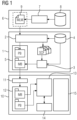
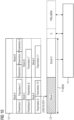
- Fig. 1 shows a schematic block diagram for illustrating a possible exemplary embodiment of a system for deployment and execution of a machine learning model MLM on a target field device.
- the deployment system 1 illustrated in Fig. 1 comprises a model parser 2 and a tool chain 3 specific to a target field device.
- the model parser 2 is configured to parse a machine learning model MLM to generate automatically at least one source code file SCF.
- the model parser 2 is configured to parse a trained machine learning model to generate automatically a set of source code files SCF.
- the source code file SCF is adapted to execute the machine learning model MLM using available resources of a target field device 10.
- the tool chain 3 of the system 1 is specific for the target field device and is adapted to transform the at least one source code file SCF into a model binary MB for deployment in a memory of the target field device.
- the tool chain 3 can comprise in a possible embodiment a compiler, a linker, a debugger and an archiver.
- the model parser 2 has access to a database 4.
- the database 4 can comprise in a possible implementation a set of libraries and device-compatible operation modules of the respective target field device. The operation modules are compatible to the target field device 10 but can still be generic in the sense that they are suitable for different field devices.
- the model parser 2 is configured to extract parameters P of the machine learning model MLM and to include the extracted parameters into the source code of at least one generated source code file SCF as constants or static variables.
- the model parser 2 is configured to extract parameters of the machine learning model MLM and to include them into a separate parameter binary PB which is deployed along with the model binary MB in a memory of the target field device 10. The variant reduces the amount of required memory but has a performance penalty.
- the model parser 2 is configured to extract parameters of the machine learning model MLM and to include them into a separate parameter file PF which is transformed into the parameter binary PB using the tool chain 3 specific to the target field device.
- the parameter binary PB is then deployed along with the model binary MB in the memory of the target field device 10.
- the model binary MB and the parameter binary PB can be stored temporarily in a memory 5 of the parsing and deployment system 1 as illustrated in Fig. 1 .
- the machine learning model MLM is a trained machine learning model MLM trained within a training system 6.
- the training system 6 comprises a machine learning model training module 7 receiving training and/or testing data from a data source 8.
- the machine learning model MLM is trained by the module 7 with the received training data and then tested with test data.
- the trained machine learning model MLM can be stored temporarily in a memory 9 of the training system 6 as illustrated in Fig. 1 .
- the training of the machine learning model MLM can be performed independently from the target field device.
- the machine learning model MLM can be trained in a model training environment and can then be applied to the parsing and deployment system 1 as shown in Fig. 1 .
- the machine learning model MLM is represented by a serialized model comprising a text or binary string which encodes a graph topology including nodes, operation of nodes, interconnection of nodes and/or parameter of nodes.
- An exemplary machine learning model MLM is illustrated in Fig. 4 .
- the parsing and the deployment system 1 is adapted to take a serialized representation of the machine learning model MLM which can be provided by a conventional model training tool and to transform it into a source code automatically. Accordingly, a user or developer does not need to produce a source code. Only a serialized machine learning model MLM has to be provided with possibly additional parameters such as names and sizes of input and/or output nodes of the machine learning model MLM.
- the machine learning model MLM can be represented by a computation graph such as illustrated in Fig. 4 .
- different nodes N represented by circles can perform operations on input data from queues Q represented by boxes and place the calculated result in output queues for the following nodes to continue processing. The operations themselves depend on a series of parameters P which are typically being automatically learned from received data.
- the machine learning model MLM provided by the training system 6 can be exported by the training system 6 as a serialized binary or text (XML, JSON) object containing the structure and operations of the computation graph as well as the learned parameters and may comprise optionally model metadata such as version numbers, units or signatures.
- the model parameters illustrated in the exemplary diagram of Fig. 4 can for instance comprise weight coefficients.
- the machine learning model MLM is parsed by the model parser 2 of the parsing and deployment system 1 to generate automatically a set of source code files SCF comprising at least one source code file and to extract parameters of the machine learning model MLM.
- the machine learning model MLM is a serialized model that comprises a text and/or binary string which encodes a description graph topology, nodes, operations and parameters, etc. that represent the machine learning model MLM.
- the extracted parameters of the machine learning model MLM are included into a source code of the at least one generated source code file SCF as constants and/or static variables.
- the extracted parameters of the machine learning model MLM are included into a separate parameter binary PB which is deployed along with a model binary MB into a memory of the target field device.
- the extracted parameters of the machine learning model MLM are included into a separate parameter file PF which is transformed into a corresponding parameter binary PB using the tool chain 3 specific to the target field device.
- the parameter binary PB is then combined with the model binary MB for deployment in a memory of the target field device.
- the model binary MB and/or parameter binary PB are deployed locally by copying them from the parsing and deployment system 1 into a memory of the target field device.
- the tool chain 3 comprises programs that receive a source code and generate automatically a software program.
- the last processing step of the tool chain 3 places the resulting binary into a memory 5 of the parsing and development system.
- the memory 5 is typically a disc of a machine where the tool chain 3 is implemented.
- the model binary MB and/or parameter binary PB can also be copied from the parsing and deployment system 1 via a network and a network interface of the target field device 10 into a local memory of the target field device 10. In general, it does not necessarily need to be transferred directly from the parsing and deployment system to the target field devices. It can be placed in some intermediate repository or system in charge of performing updates on the field device.
- the model binary MB and parameter binary PB can be stored in a possible embodiment in a non-volatile memory 12 of the target field device 10 and then loaded into a main memory 13 of the target field device 10 for execution by at least one processing unit 14 of the target field device 10.
- Fig. 1 illustrates a possible exemplary embodiment of a target field device 10 according to an aspect of the present invention.
- the target field device 10 comprises an interface 11, a processing unit 14 such as a CPU.
- the target field device 10 can comprise input and/or output interfaces 15.
- the non-volatile memory 12 can be connected to the central processing unit 14 via a memory controller.
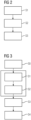
- Fig. 2 shows a possible exemplary embodiment of a method for deployment of a machine learning model MLM on a target field device 10 according to the first aspect of the present invention.
- a set of source code files SCF is generated automatically on the basis of the machine learning model MLM provided by the training system 6.
- the set of source code files SCF is adapted to execute the machine learning model MLM according to predetermined capabilities of the target field device 10.
- the generated source code files SCF are transformed into a model binary MB using the tool chain 3 specific to the target field device 10.
- the model binary MB is deployed in step S3 in a memory 12 of the target field device 10.
- This memory 12 is in a preferred embodiment a non-volatile memory.
- step S1 an automatic transformation of the machine learning model MLM into a source code is performed.
- the model parser 2 of the parsing and deployment system 1 goes through the serialized model object and replicates the computation graph topology into a syntax suitable to be compiled in a low-level language for the target field device 10, e.g. C/C++.
- the resulting source code files SCF effectively implement a standalone module where instructions and operations are instantiated in a sequence such that they result in the same computation graph as the exported machine learning model MLM.
- the generated program is optimized to execute the individual machine learning model MLM from which it is generated.
- the method as illustrated in the flowchart of Fig. 2 can be performed in the development environment of the target field device 10. It is different from the execution environment of the device 10 itself and can also be different to the environment used to train the machine learning model MLM.
- the model parser 2 of the system 1 as illustrated in Fig. 1 can make use of information about a set of libraries and modules available for the respective target field device 10, e.g. operations performed and interfaces.
- the model parser 2 has knowledge about device-specific modules for operations such as matrix multiplications, convolutions, non-linear functions, etc. which are typical building blocks of machine learning models MLM.
- These libraries can be preimplemented once in an optimized way for the deployment system 1 according to the above-mentioned qualities and requirements, and can be re-used for every new machine learning model MLM that has to be deployed.
- a computer program is automatically built, i.e. compiled and linked, from the auto-generated source code files SCF and the device-specific libraries and modules, using the tool chain 3 suitable for the target device 10.
- the result is a standalone binary program MB which can be executed on the field device 10.
- the generated model binary MB is deployed in step S3 in the memory of the target field device 10.
- the machine learning module is integrated into the firmware of the target device 10.
- the auto-generated source code is not given directly to a toolchain. Instead, the generated code is integrated with other source code implementing other functions of the field device 10. This integration can take place for example in a configuration management tool.
- all the source code auto-generated ML code and unrelated, general device source code
- Model parameters of the machine learning model MLM can be parsed in different ways.
- One alternative is to include them directly in this generated source code of the source code file SCF. For example, they are added to the source code files as initialized static variables and constants. In this way, they form part of the resulting model binary MB after the building step.
- the extracted parameters can be placed during the parsing in separate objects such as binary files.
- the machine learning model MLM is transformed automatically into a suitable form for deployment on resource-constrained target field devices 10 running real-time applications.
- the target field device 10 as illustrated in Fig. 1 receiving a model to be deployed from the parsing and deployment system 1 can be for instance a programmable logical controller PLC or an electrical grid digital protection relay.
- the generated model binary MB deployed in the memory of the target field device 10 has the advantage that it uses only the required system resources of the target field device 10 to implement the machine learning model MLM of interest. Further, the deployed model binary MB complies with run-time policies imposed by the target system or target device 10. For example, no additional memory requests to the operating system after program start are necessary and there is no exception throwing. Further, no extensive manual code development is required.
- Fig. 3 shows a block diagram of a further possible embodiment for deployment and execution of a machine learning model MLM on a target field device 10.
- a training step S0 is performed previous to the generation of the source code files SCF in step S1.
- the model binary MB is loaded in step S4 into a main memory 3 of the target field device 10 for execution.
- the deployment can take place locally by copying a file from a storage medium physically attached to the device or remotely e.g. via a network interface.
- the model can be deployed in various forms, such as integrated with a full firmware update, as a standalone library or as an executable binary. In the latter case, the functionality implemented by the model can be offered to customers as a standalone application which can be updated as improved models become available.
- the deployment can take place to a non-volatile memory of the target field device 10 or a similar permanent storage facility such as a disk drive. After this point, execution of the model in a standalone mode (without the need for a generic model interpreter capable of scoring/executing multiple different models) can take place.
- the model binary MB is initially placed into the main memory 13 by a loader. If the model parameters are contained within the model binary MB, no further transfer of information to the main memory 13 is required from the non-volatile memory 12 of the target field device 10.
- the machine learning model MLM can be executed on the target field device 10 by a processing unit with a lower and predictable amount of required system resources.
- Model training and testing can take place with standard tools independent of the restrictions and required software imposed by the target device 10. Further, the resulting program is guaranteed to run on the target device 10, i.e. it is possible to guarantee that all its dependencies are satisfied and that it complies with the requirements of the target device 10. Moreover, the resulting program is sufficient in the use of system resources and can be deployed in a standalone manner. It can contain exclusively the instructions and data required for evaluation of a single model. Hence, it does not require a generic model interpreter running on the target device 10. Further, the resulting program can be made suitable for real-time applications because it uses a fixed amount of resources and has a predictable execution time. An update of the machine learning models can be streamlined requiring in most cases no manual code development for a development and update of new machine learning models MLM.
- the invention provides according to a further aspect a method for executing a machine learning model MLM on a field device such as a field device 10 as illustrated in Fig. 1 . Further exemplary embodiments of the field device 10 are shown in Figs. 5, 6 .
- the method for executing a machine learning model MLM on a field device 10 comprises executing basic operations of the machine learning model MLM divided into operation groups of basic operations according to a schedule. The basic operations of an operation group are executed while model parameters of a subsequent operation group are loaded.
- the basic operations are executed depending on a precalculated set of execution configurations.
- the basic operations of an operation group can be executed by at least one processing unit such as the processing unit 14 illustrated in Fig. 1 of the field device 10 while model parameters of a subsequent operation group are loaded simultaneously from a non-volatile memory unit of the field device 10, such as the non-volatile memory 12, into a main memory of the field device 10, such as the main memory 13 illustrated in Fig. 1 .
- the precalculated set of execution configurations can comprise one or more of the following: a placement of operation nodes of the machine learning model MLM into operation groups of basic operations, a sequence of execution of operation nodes and/or operation groups, a selection of an amount of input and/or output batching to be performed between operation nodes of the machine learning model MLM and/or a location on a non-volatile memory 12 of the field device 10 for model parameters corresponding to operation nodes of each operation group.
- the set of execution configurations is precalculated on the basis of a graph topology of the machine learning model MLM including dependencies between operation nodes N of the machine learning model MLM, an available program memory of the field device 10 and/or an admissible execution latency and/or a load time for loading model parameters P from a memory unit of the field device 10 into a processing unit 14 of the field device 10 and/or an execution time of basic operations for each operation node of the machine learning model MLM of the field device 10.
- the model parameters P of a subsequent operation group are loaded into the main memory 13 of the field device 10 in response to load requests issued by a machine learning program implementing the machine learning model MLM and executed by a processing unit 14 of the field device 10.
- a load request is issued by the machine learning program running on the CPU 14 of the target field device 10.
- There can be a module in charge of implementing the schedule i.e. coordinate the execution of operation groups and the loading of operation parameters P according to the schedule.
- the target field device 10 comprises a single processing unit 14.
- the target field device 10 can also comprise multiple processing units, for example a multicore system or a system with additional processing units such as Graphics Processing Units (GPU) or Field Programmable Gate Arrays (FPGA).
- graphics processing Units GPU
- FPGA Field Programmable Gate Arrays
- the used machine learning model MLM can comprise different kinds of machine learning models MLM, in particular an artificial neural network, a convolutional neural network CNN, a recurrent neural network RNN, multilayer perceptrons, a decision tree model and/or a random forest model.
- the machine learning model MLM can itself be a combination, i.e. ensemble of multiple different models.
- the machine learning model MLM is typically represented by a computation graph as illustrated in Fig. 4 .
- the nodes N of the machine learning model MLM represented by circles are adapted to perform operations of input data received from input queues Q and place the results of the operation in output queues for the next layer of nodes to continue processing. Operations performed by the nodes N can be depend on a series of parameters, for instance weighting coefficients. The parameters can typically be learned automatically from data.
- the parameters P associated to the operation nodes N require memory resources on the target field device 10 which executes the model. The same applies to the queues Q between the operation nodes N which can be designed to provide capacity for multiple input output values. Additionally, the instructions to be performed by the operation nodes N as well as their internal variables also require system memory.
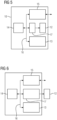
- the field device 10 which is used to run the model can comprise a main memory 13 and a non-volatile memory 12 as depicted in the embodiments of Figs. 5, 6 .
- the main memory 13 is typically fast but also costly and provides limited memory space.
- the main memory 13 can be based on technologies such as SRAM or DRAM including non-volatile or battery-packed versions.
- the main memory 13 can communicate with the processing unit 14 of the target field device 10 which executes programs, for example via a system bus 16 as illustrated in Figs. 5, 6 .
- the non-volatile memory 12 can be internal to the target device 10 as illustrated in Fig. 5 or can be external as illustrated in the embodiment of Fig. 6 .
- the non-volatile memory 12 can be implemented by a memory card such as SD cards or CFAST cards.
- the target device 10 can also comprise both types of memory cards.
- the non-volatile memory 12 is typically less costly than the main memory 13. It can be based on different technologies, for instance NAND or NOR flash memory. In general, it presents certain disadvantages compared to the main memory 13 including slow read times, slow write times and a limited lifespan due to erase and write cycles.
- the non-volatile memory 12 can be connected to the processing unit 14 of the target field device 10 via a memory controller 17 as shown in Figs. 5, 6 .
- the memory controller 17 receives requests or commands from the processing unit 14, for example via the same system bus 16.
- the memory controller 17 can be requested to provided certain pages or blocks from the non-volatile memory 12 to the processing unit 14 or to copy them directly to a certain area of the main memory 13 without CPU involvement, e.g. by using a DMA mechanism.
- the memory controller 17 is adapted to interpret requests and manages the memory accordingly in order to perform the requests. This communication can take place using several serial or parallel interfaces specific to the memory type such as SPI or SD interfaces.
- NAND flash memory typically used in memory cards
- operations must be performed in pages or blocks of certain size, wherein the size in turn depends on the nature of the operations themselves (read, write, erase).
- Placement of model parameters in the memory and access during model execution can affect performance. For instance, random access across many different pages would be substantially slower than sequential access of parameters tightly packaged in fewer pages.
- the field device 10 comprises a memory controller 17 adapted to load model parameters of a subsequent operation group from the memory unit 12 of the field device 10 into the main memory 13 of the field device 10 in response to received load requests issued by a machine learning program implementing the machine learning model MLM and executed by the processing unit 14 of the field device 10.
- the memory unit storing model parameters P of the machine learning model MLM is in a preferred embodiment a non-volatile memory 12.
- the main memory 13 for which the program running on the processing unit 14 reads data forms part of the target field device 10.
- the main memory 13 can be formed by a random access memory RAM, for example SRAM or DRAM.
- the main memory 13 can also be formed by a non-volatile RAM (nvRAM) or by a flash memory e.g. NOR flash memory.
- nvRAM non-volatile RAM
- NOR flash memory flash memory e.g. NOR flash memory.
- the non-volatile memory 12 can be typically a NAND flash memory. It can be also formed by other types of flash memories, e.g. NOR flash memory.
- the non-volatile memory 12 can be located in the target field device 10 as illustrated in Fig. 5 or located externally and connected to the target field device 10 as illustrated in Fig. 6 . It can be formed by memory card such as an SD card, MMC card, CFAST card or a USB drive or it can be formed by a hard drive.
- memory card such as an SD card, MMC card, CFAST card or a USB drive or it can be formed by a hard drive.
- a set of execution configurations EC is calculated prior to deployment.
- This set of execution configuration can comprise a placement of operation nodes of the machine learning model MLM into operation groups of basic operations, a schedule or a sequence of execution of the operation nodes and/or operation groups, a selection of the amount of input and/or output batching to be performed between operation nodes and/or a location on the device's non-volatile memory for the parameters corresponding to operation nodes on each operation group.
- the calculation of execution configuration can be performed taking into account the topology of the graph (dependencies between operation nodes), a limit of total program memory available and the execution latency.
- the calculation can further take into account a load time from the non-volatile memory 12 (for different block sizes) on the target field device 10 and/or the execution time for each operation node on the target field device 10.
- the calculation can be designed to provide execution configurations that guarantee the following: the amount of memory required at any given times does not exceed the memory limit set. In practice, this requires that the amount of memory required for the parameters of any two consecutive groups does not exceed a certain allocated amount of parameter memory. Further, the execution configurations guarantee that the latency requirements are met.
- the execution configurations are selected that maximize performance. Accordingly, the amount of CPU idle time (or wait time while parameters are loaded from the non-volatile memory 12) is minimized.
- the parameter placement in memory and schedule are consistent to increase performance (e.g. ensure sequential access to blocks if this improves the read throughput).
- the program is deployed on the target field device 10 typically in a preferred embodiment to a non-volatile memory 12. It is deployed together with the model parameters, placed on specific locations. Additionally, the program contains information about other execution configurations such as schedule and/or batching. The deployment can be done via a network interface or an external memory card can be connected to the device for copying the program and parameters.
- the program is loaded into the main memory 13 and performs a series of operations as required by the operation nodes according to the schedule provided and issues a series of requests to load coefficients from the non-volatile memory 12, also according to the schedule.
- These requests can be handled by the non-volatile memory controller in parallel to the program execution by the processing unit 14. That is, while the processing unit 14 is performing operations using a given set of parameters, a transfer of the next set of parameters from the non-volatile memory 12 to the main memory 13 can be performed in parallel.
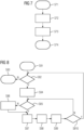
- FIG. 7 illustrates an initialization sequence while Fig. 8 illustrates the model execution on the CPU 14 of the target field device 10.
- the initialization sequence comprises four steps S71, S72, S73, S74.
- an indicator n is initialized to be 0.
- n is indicating the current operation group in the schedule.
- a request to load parameters of operation group 0 is issued.
- the initialization sequence ends in step S74.
- the model execution can be performed by the processing unit 14 of the target field device 10 as illustrated in the flow diagram of Fig. 8 .
- the model execution starts in step S81.
- step S82 it is checked whether input data is available to the machine learning model MLM or not. If there is no input data the model execution stops in step S83. If input data is available the input data is fetched in step S84. In step S85, it is checked whether the parameters P of the operation group n have been loaded. If not, the process waits in step S86 for the parameters P to be loaded and optionally other tasks are processed by the CPU 14. If in step S86 the parameters P of group n have been loaded, in step S87 it is requested to load parameters P of the next operation group (n+1) according to the schedule. Then, in step S88, a node group n is processed.
- step S810 it is checked whether n is 0 or not. If n is not 0, the process returns to step S85. If n becomes 0, the process returns to step S82 as illustrated in Fig. 8 .
- the flow diagram of Fig. 8 describes the behaviour of the program on each cycle (for example on each PLC scan cycle). The flow comprises two loops, i.e. an outer loop through the available inputs of the machine learning model MLM and an inner loop through all node groups, performing loading and execution steps in parallel.
- the exemplary simplified machine learning model MLM as illustrated in Fig. 4 has specific memory requirements or model parameters and requirements for an execution time on a particular target device 10 as given in Table 1.
- Node Param. Exec. Time 1 10 kB 12 us 2 20 kB 13 us 3 10 kB 5 us 4 10 kB 10 us 5 10 kB 8 us 6 10 kB 10 us 7 25 kB 25 us 8 22 kB 14 us 9 15 kB 10 us 10 15 kB 15 us 11 28 kB 24 us Total 175 kB 146 us
- the best scenario for execution time of the model for a given input is 146 us. That would be the case if all parameters of the model are in memory occupying a memory space of 175 kB and no loading of parameters P is required. It is, however, possible to optimize the execution so that much less memory is utilized, with a minimal penalty on the execution time.
- the target device 10 comprises an NAND flash non-volatile memory 12 where the page size is 16 kB and a page can be loaded to the main memory 13 of the target device 10 within 50 ⁇ s. It is possible to place the operation nodes of the model into groups, for example as indicated in Table 2. Group Nodes Mem. Position Schedule Batch Group 1 1, 2 Block A Step 1 4 Group 2 3, 4, 5 Block B Step 2 4 Group 3 6, 8 Block C Step 3 4 Group 4 7 Block D Step 4 4 Group 5 9, 10 Block E Step 5 4 Group 6 11 Block F Step 6 4
- the grouping is such that the parameters in an operation group fit in two pages (32 kB). Loading from the non-volatile memory 12 the parameters for an operation group takes approximately 100 ⁇ s, and processing the group takes 25 us in a worst case. For these values, an execution strategy would be to use just 64 kB of the main memory 13 (the equivalent of four pages) where at any given time two of them are being used by the running program processing a given group of nodes, and another two are being loaded with the parameters for the next or subsequent operation group.
- the wait time while operation parameters are being loaded is minimized.
- the minimum can be achieved when the execution time of the current group is the same as the loading time of the next group.
- This can be tuned, for example, via batching of many inputs. Assuming that the overhead for storing an additional set of intermediate elements is small compared to the amount of parameters of the operation nodes and that a latency of up to 1 ms is acceptable for a model input to be processed it is possible to batch four inputs together to have a worst case execution time for a group of 100 ⁇ s, comparable with the time to load parameters of each group.
- Fig. 10 shows the state of memory in the given example during execution of nodes in group 4, while loading of parameters of nodes in group 5.
- the system processes four different inputs applied to the model in approximately 600 ⁇ s, that is, on average 150 us, adding a very small overhead compared to the best case where all parameters are in the memory at once (146 ⁇ s).
- the scheduling does not exceed the latency requirement and uses a reduced amount of memory, e.g. 64 kB for parameters and a small overhead for queues.
- Fig. 9 illustrates the interaction between the processing unit 14 and the memory controller 17 of a target device 10.
- the load requests are issued by a machine learning program running on the processing unit 14.
- a component of the program can be in charge of implementing the schedule, i.e. coordinate the execution of operation groups and the loading of operation parameters according to the schedule.
- the basic operations of an operation group are executed by performing processing of data with the loaded parameters by the CPU 14 while in parallel normal parameters of a subsequent operation group are loaded by the memory controller 17.
- the non-volatile memory 12 of the target device 10 stores the parameters P of the machine learning model MLM illustrated in Fig. 4 .
- the machine learning model MLM of Fig. 4 comprises eleven operation nodes N with associated operation parameters P.
- the parameters P such as weighting coefficients or the different operation nodes N of the machine learning model MLM are stored in memory blocks A to F of the non-volatile memory 12 as illustrated in Fig. 10 .
- the grouping is such that the parameters P in a group fit in two pages (32 kB). For instance, the operation nodes 1, 2 of the machine learning model MLM of Fig. 4 require 10 kB plus 20 kB, i.e.
- the main memory 13 comprises a parameter memory space for two blocks, block E and block D in the give example. Further, the main memory 13 has additional memory space for the queues Q of the machine learning model MLM and can comprise a fixed program memory including instructions and data.
- the central processing unit CPU 14 of the target device 10 has direct access to the main memory 13 as illustrated in Fig. 10 .
- the parameters of block E i.e. group 5 comprising nodes 9, 10 are loaded while parameters P of block D are processed by the processing unit 14. Accordingly, the basic operations of the operation group related to operation node 7 of the machine learning model (loaded from block D of non-volatile memory 12) are executed while at the same time parameters P of a subsequent operation group 5 comprising operation nodes 9, 10 of the machine learning model MLM are loaded from block E of the non-volatile memory 12.
- the method according to the present invention is adapted to process, store and evaluate machine learning models MLM on target field devices 10 in such a way that the amount of main memory 13 required is reduced. This makes it possible to evaluate large machine learning models MLM or making execution of small machine learning models MLM more efficient. Further, the method for executing a machine learning model on a field device 10 according to the third aspect of the present invention does minimize the idle time waiting for parameters P to be loaded, that is it reduces the overhead added when compared to an ideal scenario (having always all parameters stored in the main memory 13).
- the operations in a machine learning model MLM can be grouped and the corresponding parameters P of each group can be stored in the non-volatile memory 12 in specific locations.
- a predetermined schedule is followed such that the execution of a group of operations and the loading of the parameters P of the next group into the main memory 13 can be performed in parallel.
- the method enables the deployment and execution of arbitrarily large machine learning models MLMs and/or artificial intelligence algorithms and models into industrial field devices such as PLCs which comprise a restricted amount of memory resources.
Landscapes
- Engineering & Computer Science (AREA)
- Software Systems (AREA)
- Theoretical Computer Science (AREA)
- General Engineering & Computer Science (AREA)
- Physics & Mathematics (AREA)
- General Physics & Mathematics (AREA)
- Artificial Intelligence (AREA)
- Computer Vision & Pattern Recognition (AREA)
- Data Mining & Analysis (AREA)
- Evolutionary Computation (AREA)
- Medical Informatics (AREA)
- Computing Systems (AREA)
- Mathematical Physics (AREA)
- Stored Programmes (AREA)
- Devices For Executing Special Programs (AREA)
Claims (8)
- Verfahren zum Einsetzen eines Maschinenlernmodells (MLM) auf einer Zielfeldvorrichtung (10), umfassend die folgenden Schritte:(a) automatisches Erzeugen (S1) eines Satzes von Quellcodedateien (SCF) basierend auf einem trainierten Maschinenlernmodell, wobei das Maschinenlernmodell durch einen computergestützten Graphen dargestellt wird, der Knoten (N) umfasst, die Operationen auf Eingabedaten aus Warteschlangen (Q) durchführen und das berechnete Ergebnis in Ausgabewarteschlangen für die nachfolgenden Knoten ablegen, um die Verarbeitung fortzusetzen, wobei die Operationen von einer Reihe von Parametern (P) abhängen, die erlernt werden,wobei der Satz von Quellcodedateien (SCF) dazu eingerichtet ist, das Maschinenlernmodell unter Verwendung der verfügbaren Ressourcen der Zielfeldvorrichtung (10) auszuführen,wobei das Maschinenlernmodell (MLM) durch ein serialisiertes Modell dargestellt wird, das einen Text oder eine binäre Zeichenkette umfasst, die eine Graph-Topologie einschließlich Knoten, Betrieb von Knoten, Verbindung von Knoten und Parameter von Knoten codiert;wobei das Maschinenlernmodell durch einen Modellparser (2) geparst wird, um automatisch mindestens eine Quellcodedatei (SCF) zu erzeugen und um Parameter des Maschinenlernmodells zu extrahieren,wobei der Modellparser (2) das serialisierte Modellobjekt durchläuft und die Topologie des computergestützten Graphen in eine Syntax repliziert, die geeignet ist, um in einer Low-Level-Sprache für die Zielfeldvorrichtung (10) kompiliert zu werden, undwobei der Modellparser (2) Informationen über Bibliotheken und Module verwendet, die für die Zielfeldvorrichtung (10) verfügbar sind;(b) Umwandeln (S2) der erzeugten Quellcodedateien (SCF) in eine Modellbinärdatei (MB) unter Verwendung einer für die Zielfeldvorrichtung (10) spezifischen Werkzeugkette (3), wobei die Werkzeugkette (3) einen Compiler, einen Linker, einen Debugger, einen Archivierer und Programme umfasst, die einen Quellcode empfangen und automatisch ein Softwareprogramm erzeugen; und(c) Bereitstellen (S3) des binären Modells (MB) in einem Speicher (12) der Zielfeldvorrichtung (10); und(d) die extrahierten Parameter des Maschinenlernmodells (MLM) sind in einer separaten Parameterdatei (PF) enthalten, die unter Verwendung der Werkzeugkette (3) speziell für die Zielfeldvorrichtung (10) in eine Parameterbinärdatei (PB) umgewandelt wird, wobei die Parameterbinärdatei (PB) mit der Modellbinärdatei (MB) zur Bereitstellung in einem Speicher der Zielfeldvorrichtung (10) kombiniert wird,wobei das binäre Modell (MB) in einen Hauptspeicher (3, 13) der Feldvorrichtung (10) geladen wird;wobei die extrahierten Parameter des Maschinenlernmodells (MLM) Gewichtskoeffizienten sind und in einer separaten Parameterbinärdatei (PB) enthalten sind, die in einem nichtflüchtigen Speicher (12) der Zielfeldvorrichtung (10) bereitgestellt wird, wobei die Feldvorrichtung (10) eine Speichersteuervorrichtung (17) umfasst, die dazu ausgelegt ist, gleichzeitig mit der Ausführung einer aktuellen Betriebsgruppe als Reaktion auf eine Empfangsladeanforderung, die durch das Maschinenlernmodellprogramm, das das Maschinenlernmodell implementiert, ausgegeben und durch eine Verarbeitungseinheit (14) der Feldvorrichtung (10) ausgeführt wird, Modellparameter aus einer nachfolgenden Betriebsgruppe aus dem nicht flüchtigen Speicher (12) in den Hauptspeicher (13) zu laden.
- Verfahren gemäß Anspruch 1, wobei die extrahierten Parameter des Maschinenlernmodells (MLM) in einem Quellcode mindestens einer erzeugten Quellcodedatei (SCF) als Konstanten und/oder statische Variablen enthalten sind.
- Verfahren gemäß einem der vorhergehenden Ansprüche, wobei das Maschinenlernmodell (MLM), das zum Erzeugen der Quellcodedateien (SCF) verwendet wird, ein Maschinenlernmodell umfasst, das mit Trainingsdaten trainiert und/oder mit Testdaten getestet wurde.
- Verfahren gemäß einem der vorhergehenden Ansprüche 1 bis 3, wobei das Maschinenlernmodell (MLM) durch einen Modellparser (2) geparst wird, der Zugang zu einer Datenquelle (4) aufweist, die einen Satz von Bibliotheken und mit der Vorrichtung kompatiblen Betriebsmodulen der Zielfeldvorrichtung (10) umfasst.
- Verfahren gemäß Anspruch 1, wobei vor dem Erzeugen einer Modellbinärdatei (MB) der erzeugte Quellcode mit anderem Quellcode der Vorrichtung integriert wird.
- Einsatzsystem für den Einsatz eines Maschinenlernmodells (MLM) auf einer Zielfeldvorrichtung (10),
wobei das Einsatzsystem (1) Folgendes umfasst:- einen Modellparser (2), der dazu ausgelegt ist, das Maschinenlernmodell (MLM) zu parsen, um mindestens eine Quellcodedatei (SCF) zu erzeugen, die dazu eingerichtet ist, das Maschinenlernmodell unter Verwendung verfügbarer Ressourcen der Zielfeldvorrichtung (10) auszuführen, wobei das Maschinenlernmodell durch einen computergestützten Graphen dargestellt wird, der Knoten (N) umfasst, die Operationen an Eingabedaten aus Warteschlangen (Q) durchführen und das berechnete Ergebnis in Ausgabewarteschlangen für die nachfolgenden Knoten ablegen, um die Verarbeitung fortzusetzen, wobei die Operationen von einer Reihe von Parametern (P) abhängen, die erlernt werden,wobei der Modellparser (2) ferner dazu ausgelegt ist, das serialisierte Modellobjekt zu durchlaufen und die Topologie des computergestützten Graphen in eine Syntax zu replizieren, die geeignet ist, um in einer Low-Level-Sprache für die Zielfeldvorrichtung (10) kompiliert zu werden, undwobei der Modellparser (2) ferner dazu ausgelegt ist, Informationen über Bibliotheken und Module zu verwenden, die für die Zielfeldvorrichtung (10) verfügbar sind; und- eine für die Zielfeldvorrichtung (10) spezifische Werkzeugkette (3), die dazu eingerichtet ist, die mindestens eine Quellcodedatei (SCF) in eine Modellbinärdatei (MB) zur Bereitstellung in einem Speicher (12) der Zielfeldvorrichtung (10) umzuwandeln, wobei die Werkzeugkette (3) einen Compiler, einen Linker, einen Debugger, einen Archivierer und Programme umfasst, die einen Quellcode empfangen und automatisch ein Softwareprogramm erzeugen; und- wobei der Modellparser (2) dazu ausgelegt ist, Parameter des Maschinenlernmodells (MLM) zu extrahieren und in eine separate Parameterdatei (PF) einzubinden, die unter Verwendung der für die Zielfeldvorrichtung (10) spezifischen Werkzeugkette (3) in eine Parameterbinärdatei (PB) umgewandelt wird, wobei die Parameterbinärdatei (PB) zusammen mit der Modellbinärdatei (MB) in einem Speicher (12) der Zielfeldvorrichtung (10) bereitgestellt wird,- eine Feldvorrichtung (10), umfassend:einen Hauptspeicher (3, 13), in den das binäre Modell (MB) geladen wird,einen nichtflüchtigen Speicher (12), in den eine separate Parameterbinärdatei (PB) geladen wird, wobei die extrahierten Parameter des Maschinenlernmodells (MLM), die Gewichtskoeffizienten sind, in der separaten Parameterbinärdatei (PB) enthalten sind,eine Speichersteuervorrichtung (17), die dazu ausgelegt ist, gleichzeitig mit der Ausführung einer aktuellen Betriebsgruppe als Reaktion auf eine Empfangsladeanforderung, die durch das Maschinenlernmodellprogramm, das das Maschinenlernmodell implementiert, ausgegeben und durch eine Verarbeitungseinheit (14) der Feldvorrichtung (10) ausgeführt wird, Modellparameter aus einer nachfolgenden Betriebsgruppe aus dem nichtflüchtigen Speicher (12) in den Hauptspeicher (13) zu laden. - Einsatzsystem gemäß Anspruch 6, wobei der Modellparser (2) Zugriff auf eine Datenbank (4) aufweist, die einen Satz von Bibliotheken und mit der Vorrichtung kompatiblen Betriebsmodulen der Zielfeldvorrichtung (10) umfasst.
- Einsatzsystem gemäß einem der vorhergehenden Ansprüche 6 oder 7, wobei der Modellparser (2) dazu ausgelegt ist, Parameter des Maschinenlernmodells (MLM) zu extrahieren und in einen Quellcode mindestens einer erzeugten Quellcodedatei (SCF) als Konstanten und/oder statische Variablen einzubinden.
Applications Claiming Priority (2)
| Application Number | Priority Date | Filing Date | Title |
|---|---|---|---|
| EP17161110.6A EP3376373A1 (de) | 2017-03-15 | 2017-03-15 | Verfahren zum einsetzen und ausführen eines maschinenlernmodells auf einer feldvorrichtung |
| PCT/EP2018/055008 WO2018166801A1 (en) | 2017-03-15 | 2018-03-01 | A method for deployment and execution of a machine learning model on a field device |
Publications (3)
| Publication Number | Publication Date |
|---|---|
| EP3580655A1 EP3580655A1 (de) | 2019-12-18 |
| EP3580655C0 EP3580655C0 (de) | 2024-02-21 |
| EP3580655B1 true EP3580655B1 (de) | 2024-02-21 |
Family
ID=58578810
Family Applications (2)
| Application Number | Title | Priority Date | Filing Date |
|---|---|---|---|
| EP17161110.6A Withdrawn EP3376373A1 (de) | 2017-03-15 | 2017-03-15 | Verfahren zum einsetzen und ausführen eines maschinenlernmodells auf einer feldvorrichtung |
| EP18710379.1A Active EP3580655B1 (de) | 2017-03-15 | 2018-03-01 | Verfahren zum einsetzen und ausführen eines maschinenlernmodells auf einer feldvorrichtung |
Family Applications Before (1)
| Application Number | Title | Priority Date | Filing Date |
|---|---|---|---|
| EP17161110.6A Withdrawn EP3376373A1 (de) | 2017-03-15 | 2017-03-15 | Verfahren zum einsetzen und ausführen eines maschinenlernmodells auf einer feldvorrichtung |
Country Status (4)
| Country | Link |
|---|---|
| US (1) | US10942754B2 (de) |
| EP (2) | EP3376373A1 (de) |
| CN (1) | CN110637286B (de) |
| WO (1) | WO2018166801A1 (de) |
Families Citing this family (25)
| Publication number | Priority date | Publication date | Assignee | Title |
|---|---|---|---|---|
| CN108764487B (zh) * | 2018-05-29 | 2022-07-08 | 北京百度网讯科技有限公司 | 用于生成模型的方法和装置、用于识别信息的方法和装置 |
| WO2019232471A1 (en) | 2018-06-01 | 2019-12-05 | Nami Ml Inc. | Machine learning at edge devices based on distributed feedback |
| DE102018123792A1 (de) | 2018-09-26 | 2020-03-26 | Thyssenkrupp Ag | Verfahren zur Regelung eines chemischen Prozesses in einer großtechnischen chemischen Anlage |
| CN111507476A (zh) * | 2019-01-31 | 2020-08-07 | 伊姆西Ip控股有限责任公司 | 部署机器学习模型的方法、设备和计算机程序产品 |
| CN110308910B (zh) * | 2019-05-30 | 2023-10-31 | 苏宁金融服务(上海)有限公司 | 算法模型部署以及风险监控的方法、装置和计算机设备 |
| WO2020246920A1 (en) * | 2019-06-04 | 2020-12-10 | Telefonaktiebolaget Lm Ericsson (Publ) | Executing machine-learning models |
| US11551118B2 (en) * | 2019-06-05 | 2023-01-10 | Koninklijke Philips N.V. | Tuning implementation of machine learning model for resource-constrained device |
| PL3757583T3 (pl) * | 2019-06-25 | 2023-05-08 | Reactive Technologies Limited | System do wyznaczania parametrów elektrycznych sieci elektroenergetycznej |
| EP3997530B1 (de) * | 2019-08-16 | 2023-11-08 | Siemens Aktiengesellschaft | Künstliche intelligenz für engineering in der automatisierungstechnik |
| CN112529206B (zh) * | 2019-09-18 | 2024-05-17 | 华为技术有限公司 | 一种模型运行方法和系统 |
| EP3809214B1 (de) * | 2019-10-14 | 2025-07-30 | Siemens Aktiengesellschaft | Verfahren zum konfigurieren einer schnittstellenvorrichtung und schnittstellenvorrichtung damit |
| CN113298843B (zh) | 2020-02-24 | 2024-05-14 | 中科寒武纪科技股份有限公司 | 数据量化处理方法、装置、电子设备和存储介质 |
| WO2021248443A1 (en) * | 2020-06-12 | 2021-12-16 | Qualcomm Incorporated | Generate source code to build secure machine learning engine for edge devices and existing toolchains |
| US11861469B2 (en) * | 2020-07-02 | 2024-01-02 | International Business Machines Corporation | Code generation for Auto-AI |
| EP3958423A1 (de) * | 2020-08-19 | 2022-02-23 | Hitachi Energy Switzerland AG | Verfahren und rechnersystem zur erzeugung einer entscheidungslogik für einen regler |
| CN111966382A (zh) * | 2020-08-28 | 2020-11-20 | 上海寻梦信息技术有限公司 | 机器学习模型的在线部署方法、装置及相关设备 |
| CN112947960A (zh) * | 2021-02-05 | 2021-06-11 | 中国建设银行股份有限公司 | 一种基于机器学习的风险模型部署方法及系统 |
| US20220318656A1 (en) * | 2021-03-30 | 2022-10-06 | EMC IP Holding Company LLC | Model parameter sharing between inference application instances in processing unit of information processing system |
| CN114268903B (zh) * | 2021-12-28 | 2022-09-30 | 北京航空航天大学 | 一种地理信息辅助的无人机中继位置部署以及功率分配方法 |
| US11922772B2 (en) | 2022-04-08 | 2024-03-05 | Konami Gaming, Inc. | Gaming machine and method of operating a gaming machine including primary and secondary memory storage devices |
| CN115018048B (zh) * | 2022-05-26 | 2025-09-02 | 杭州电子科技大学 | 一种可编程控制器中机器学习功能块执行机制及方法 |
| US20240037150A1 (en) * | 2022-08-01 | 2024-02-01 | Qualcomm Incorporated | Scheduling optimization in sequence space |
| CN115357309B (zh) * | 2022-10-24 | 2023-07-14 | 深信服科技股份有限公司 | 一种数据处理方法、装置、系统和计算机可读存储介质 |
| CN115981634B (zh) * | 2022-12-22 | 2026-02-17 | 北京四方继保自动化股份有限公司 | 一种基于数据建模的电力保护方法及装置 |
| US12547379B2 (en) * | 2024-01-26 | 2026-02-10 | Alex Schiffman | Generating target language code from source language code |
Family Cites Families (10)
| Publication number | Priority date | Publication date | Assignee | Title |
|---|---|---|---|---|
| FR2865047B1 (fr) * | 2004-01-14 | 2006-04-07 | Commissariat Energie Atomique | Systeme de generation automatique de codes optimises |
| US8015543B1 (en) * | 2007-01-10 | 2011-09-06 | The Mathworks, Inc. | Hardware specific code generation |
| US20130125093A1 (en) * | 2011-11-11 | 2013-05-16 | General Electric Company | Generating object-oriented programming language code from a multi-domain dynamic simulation model |
| US8849747B2 (en) * | 2012-04-24 | 2014-09-30 | Sap Ag | Business process management |
| US10318882B2 (en) * | 2014-09-11 | 2019-06-11 | Amazon Technologies, Inc. | Optimized training of linear machine learning models |
| US10452992B2 (en) * | 2014-06-30 | 2019-10-22 | Amazon Technologies, Inc. | Interactive interfaces for machine learning model evaluations |
| US9672474B2 (en) * | 2014-06-30 | 2017-06-06 | Amazon Technologies, Inc. | Concurrent binning of machine learning data |
| EP4224309B1 (de) * | 2015-08-05 | 2025-05-21 | Equifax, Inc. | Modellintegrationswerkzeug |
| US10438132B2 (en) * | 2015-12-16 | 2019-10-08 | Accenture Global Solutions Limited | Machine for development and deployment of analytical models |
| US11080435B2 (en) * | 2016-04-29 | 2021-08-03 | Accenture Global Solutions Limited | System architecture with visual modeling tool for designing and deploying complex models to distributed computing clusters |
-
2017
- 2017-03-15 EP EP17161110.6A patent/EP3376373A1/de not_active Withdrawn
-
2018
- 2018-03-01 US US16/492,302 patent/US10942754B2/en active Active
- 2018-03-01 WO PCT/EP2018/055008 patent/WO2018166801A1/en not_active Ceased
- 2018-03-01 CN CN201880032293.8A patent/CN110637286B/zh active Active
- 2018-03-01 EP EP18710379.1A patent/EP3580655B1/de active Active
Non-Patent Citations (12)
| Title |
|---|
| ANONYMOUS: "How to save model trained by keras? . Issue #1069 . keras-team/keras . GitHub", 11 August 2016 (2016-08-11), XP093052801, Retrieved from the Internet <URL:https://github.com/keras-team/keras/issues/1069> [retrieved on 20230608] * |
| ANONYMOUS: "python - How to load a model from an HDF5 file in Keras? - Stack Overflow", 29 January 2016 (2016-01-29), XP093052752, Retrieved from the Internet <URL:https://stackoverflow.com/questions/35074549/how-to-load-a-model-from-an-hdf5-file-in-keras> [retrieved on 20230608] * |
| ANONYMOUS: "S7-GRAPH V5.3 for S7-300/400 Programming Sequential Control Systems", 1 February 2004 (2004-02-01), XP093001565, Retrieved from the Internet <URL:https://cache.industry.siemens.com/dl/files/630/1137630/att_28560/v1/Graph7_e.pdf> [retrieved on 20221124] * |
| ANONYMOUS: "SIMATIC Programming with STEP 7 - pages 401-702", 1 May 2010 (2010-05-01), XP093001579, Retrieved from the Internet <URL:https://cache.industry.siemens.com/dl/files/107/45531107/att_91661/v1/S7pr___b.pdf> [retrieved on 20221124] * |
| ANONYMOUS: "SIMATIC Programming with STEP 7", 1 May 2010 (2010-05-01), XP093000655, Retrieved from the Internet <URL:https://cache.industry.siemens.com/dl/files/107/45531107/att_91661/v1/S7pr___b.pdf> [retrieved on 20221122] * |
| ANONYMOUS: "Toolchain - Wikipedia", 31 January 2017 (2017-01-31), XP093001966, Retrieved from the Internet <URL:https://en.wikipedia.org/w/index.php?title=Toolchain&oldid=762881540> [retrieved on 20221125] * |
| ANONYMOUS: "Tutorial Siemens PLC Simatic S7-300 STEP7 WinCC Flexible", 9 May 2013 (2013-05-09), XP093000641, Retrieved from the Internet <URL:https://plc.opdenbrouw.nl/TutorialSiemensPLC.pdf> [retrieved on 20221122] * |
| JEAN-MARIE FARINES ET AL: "A model-driven engineering approach to formal verification of PLC programs", EMERGING TECHNOLOGIES&FACTORY AUTOMATION (ETFA), 2011 IEEE 16TH CONFERENCE ON, IEEE, 5 September 2011 (2011-09-05), pages 1 - 8, XP031961302, ISBN: 978-1-4577-0017-0, DOI: 10.1109/ETFA.2011.6058983 * |
| RAGHUVANSHI ARUSHI ET AL: "Facial Expression Recognition with Convolutional Neural Networks", 1 January 2016 (2016-01-01), XP093052745, Retrieved from the Internet <URL:http://cs231n.stanford.edu/reports/2016/pdfs/023_Report.pdf> [retrieved on 20230608] * |
| SIMIC DE TORRES: "ANALYSIS OF SATELLITE IMAGES TO TRACK DEFORESTATION", 1 June 2016 (2016-06-01), XP093052751, Retrieved from the Internet <URL:https://upcommons.upc.edu/bitstream/handle/2117/98551/Analysis_of_satellite_images_to_track_deforestation.pdf> [retrieved on 20230608] * |
| SIMROS MARKUS ET AL: "PROGRAMMING EMBEDDED DEVICES IN IEC 61131-LANGUAGES WITH INDUSTRIAL PLC TOOLS USING PLCOPEN XML", 18 July 2012 (2012-07-18), XP093001060, Retrieved from the Internet <URL:https://www.researchgate.net/profile/S_Theurich/publication/272773580_Programming_embedded_devices_in_IEC_61131-languages_with_industrial_PLC_tools_using_PLCopen_XML/links/54eda6900cf24a16e6070c76.pdf> [retrieved on 20221123] * |
| WAN JIANG ET AL: "Model-based design of time-triggered real-time embedded systems for digital manufacturing", MULTIMEDIA, ACM, 2 PENN PLAZA, SUITE 701 NEW YORK NY 10121-0701 USA, 14 April 2015 (2015-04-14), pages 295 - 296, XP058509772, ISBN: 978-1-4503-3459-4, DOI: 10.1145/2728606.2728651 * |
Also Published As
| Publication number | Publication date |
|---|---|
| EP3376373A1 (de) | 2018-09-19 |
| US20200012500A1 (en) | 2020-01-09 |
| EP3580655C0 (de) | 2024-02-21 |
| CN110637286B (zh) | 2023-12-05 |
| WO2018166801A1 (en) | 2018-09-20 |
| US10942754B2 (en) | 2021-03-09 |
| EP3580655A1 (de) | 2019-12-18 |
| CN110637286A (zh) | 2019-12-31 |
Similar Documents
| Publication | Publication Date | Title |
|---|---|---|
| EP3580655B1 (de) | Verfahren zum einsetzen und ausführen eines maschinenlernmodells auf einer feldvorrichtung | |
| EP3376441B1 (de) | Verfahren zur ausführung eines maschinenlernmodells auf einer speicherbeschränkten industriellen vorrichtung | |
| CN115525287A (zh) | 多阶段编译器架构 | |
| US11733983B2 (en) | Method and apparatus for generating metadata by a compiler | |
| US11022950B2 (en) | Resilient failover of industrial programmable logic controllers | |
| CN111066039A (zh) | 包括企业模型的微处理器 | |
| CN115344275A (zh) | 操作系统的镜像文件生成方法、装置和计算机设备 | |
| CN103718159A (zh) | 图像处理软件开发方法、图像处理软件开发装置和图像处理软件开发程序 | |
| JP4965995B2 (ja) | プログラム処理方法、処理プログラム及び情報処理装置 | |
| Garanina et al. | Model checking programs in process-oriented IEC 61131-3 structured text | |
| CN112130723B (zh) | 用于针对数据执行特征处理的方法及系统 | |
| US12073200B2 (en) | Compiler device, instruction generation method, program, compiling method, and compiler program | |
| US12190086B1 (en) | Method and apparatus for ML graphs by a compiler | |
| CN118276884A (zh) | 容器封装方法、装置、设备及存储介质 | |
| CN113704687B (zh) | 一种张量计算运行方法、装置及运算系统 | |
| Subero | Embedded systems overview | |
| CN114064225A (zh) | 一种自适应调度方法、装置、计算机存储介质及系统 | |
| Lecomte et al. | A safety flasher developed with the CLEARSY safety platform | |
| Nazar Shahsavani et al. | Efficient compilation and mapping of fixed function combinational logic onto digital signal processors targeting neural network inference and utilizing high-level synthesis | |
| US20210141725A1 (en) | Computing system operating a reflective memory network | |
| CN119002928B (zh) | 一种面向dots的结构体优化方法、系统、设备及介质 | |
| Garanina et al. | Autotuning Parallel Programs by Model Checking | |
| KR20230023762A (ko) | 하드웨어 오토로더 | |
| Mishra et al. | FROM APPOSITE PREFERENCE TO SPECIFIC APPLICATION: AN OVERVIEW OF MICROCONTROLLER UNIT | |
| Audsley | Towards the Codesign of Large Complex Hard Real-Time Embedded Systems |
Legal Events
| Date | Code | Title | Description |
|---|---|---|---|
| STAA | Information on the status of an ep patent application or granted ep patent |
Free format text: STATUS: UNKNOWN |
|
| STAA | Information on the status of an ep patent application or granted ep patent |
Free format text: STATUS: THE INTERNATIONAL PUBLICATION HAS BEEN MADE |
|
| PUAI | Public reference made under article 153(3) epc to a published international application that has entered the european phase |
Free format text: ORIGINAL CODE: 0009012 |
|
| STAA | Information on the status of an ep patent application or granted ep patent |
Free format text: STATUS: REQUEST FOR EXAMINATION WAS MADE |
|
| 17P | Request for examination filed |
Effective date: 20190913 |
|
| AK | Designated contracting states |
Kind code of ref document: A1 Designated state(s): AL AT BE BG CH CY CZ DE DK EE ES FI FR GB GR HR HU IE IS IT LI LT LU LV MC MK MT NL NO PL PT RO RS SE SI SK SM TR |
|
| AX | Request for extension of the european patent |
Extension state: BA ME |
|
| DAV | Request for validation of the european patent (deleted) | ||
| DAX | Request for extension of the european patent (deleted) | ||
| STAA | Information on the status of an ep patent application or granted ep patent |
Free format text: STATUS: EXAMINATION IS IN PROGRESS |
|
| 17Q | First examination report despatched |
Effective date: 20211125 |
|
| GRAP | Despatch of communication of intention to grant a patent |
Free format text: ORIGINAL CODE: EPIDOSNIGR1 |
|
| STAA | Information on the status of an ep patent application or granted ep patent |
Free format text: STATUS: GRANT OF PATENT IS INTENDED |
|
| INTG | Intention to grant announced |
Effective date: 20231019 |
|
| GRAS | Grant fee paid |
Free format text: ORIGINAL CODE: EPIDOSNIGR3 |
|
| GRAA | (expected) grant |
Free format text: ORIGINAL CODE: 0009210 |
|
| STAA | Information on the status of an ep patent application or granted ep patent |
Free format text: STATUS: THE PATENT HAS BEEN GRANTED |
|
| AK | Designated contracting states |
Kind code of ref document: B1 Designated state(s): AL AT BE BG CH CY CZ DE DK EE ES FI FR GB GR HR HU IE IS IT LI LT LU LV MC MK MT NL NO PL PT RO RS SE SI SK SM TR |
|
| REG | Reference to a national code |
Ref country code: GB Ref legal event code: FG4D |
|
| REG | Reference to a national code |
Ref country code: CH Ref legal event code: EP |
|
| REG | Reference to a national code |
Ref country code: IE Ref legal event code: FG4D |
|
| REG | Reference to a national code |
Ref country code: DE Ref legal event code: R096 Ref document number: 602018065493 Country of ref document: DE |
|
| U01 | Request for unitary effect filed |
Effective date: 20240226 |
|
| U07 | Unitary effect registered |
Designated state(s): AT BE BG DE DK EE FI FR IT LT LU LV MT NL PT SE SI Effective date: 20240304 |
|
| U20 | Renewal fee for the european patent with unitary effect paid |
Year of fee payment: 7 Effective date: 20240318 |
|
| REG | Reference to a national code |
Ref country code: LT Ref legal event code: MG9D |
|
| PG25 | Lapsed in a contracting state [announced via postgrant information from national office to epo] |
Ref country code: IS Free format text: LAPSE BECAUSE OF FAILURE TO SUBMIT A TRANSLATION OF THE DESCRIPTION OR TO PAY THE FEE WITHIN THE PRESCRIBED TIME-LIMIT Effective date: 20240621 |
|
| PG25 | Lapsed in a contracting state [announced via postgrant information from national office to epo] |
Ref country code: GR Free format text: LAPSE BECAUSE OF FAILURE TO SUBMIT A TRANSLATION OF THE DESCRIPTION OR TO PAY THE FEE WITHIN THE PRESCRIBED TIME-LIMIT Effective date: 20240522 |
|
| PG25 | Lapsed in a contracting state [announced via postgrant information from national office to epo] |
Ref country code: RS Free format text: LAPSE BECAUSE OF FAILURE TO SUBMIT A TRANSLATION OF THE DESCRIPTION OR TO PAY THE FEE WITHIN THE PRESCRIBED TIME-LIMIT Effective date: 20240521 Ref country code: HR Free format text: LAPSE BECAUSE OF FAILURE TO SUBMIT A TRANSLATION OF THE DESCRIPTION OR TO PAY THE FEE WITHIN THE PRESCRIBED TIME-LIMIT Effective date: 20240221 |
|
| PG25 | Lapsed in a contracting state [announced via postgrant information from national office to epo] |
Ref country code: ES Free format text: LAPSE BECAUSE OF FAILURE TO SUBMIT A TRANSLATION OF THE DESCRIPTION OR TO PAY THE FEE WITHIN THE PRESCRIBED TIME-LIMIT Effective date: 20240221 |
|
| PG25 | Lapsed in a contracting state [announced via postgrant information from national office to epo] |
Ref country code: RS Free format text: LAPSE BECAUSE OF FAILURE TO SUBMIT A TRANSLATION OF THE DESCRIPTION OR TO PAY THE FEE WITHIN THE PRESCRIBED TIME-LIMIT Effective date: 20240521 Ref country code: NO Free format text: LAPSE BECAUSE OF FAILURE TO SUBMIT A TRANSLATION OF THE DESCRIPTION OR TO PAY THE FEE WITHIN THE PRESCRIBED TIME-LIMIT Effective date: 20240521 Ref country code: IS Free format text: LAPSE BECAUSE OF FAILURE TO SUBMIT A TRANSLATION OF THE DESCRIPTION OR TO PAY THE FEE WITHIN THE PRESCRIBED TIME-LIMIT Effective date: 20240621 Ref country code: HR Free format text: LAPSE BECAUSE OF FAILURE TO SUBMIT A TRANSLATION OF THE DESCRIPTION OR TO PAY THE FEE WITHIN THE PRESCRIBED TIME-LIMIT Effective date: 20240221 Ref country code: GR Free format text: LAPSE BECAUSE OF FAILURE TO SUBMIT A TRANSLATION OF THE DESCRIPTION OR TO PAY THE FEE WITHIN THE PRESCRIBED TIME-LIMIT Effective date: 20240522 Ref country code: ES Free format text: LAPSE BECAUSE OF FAILURE TO SUBMIT A TRANSLATION OF THE DESCRIPTION OR TO PAY THE FEE WITHIN THE PRESCRIBED TIME-LIMIT Effective date: 20240221 |
|
| PG25 | Lapsed in a contracting state [announced via postgrant information from national office to epo] |
Ref country code: PL Free format text: LAPSE BECAUSE OF FAILURE TO SUBMIT A TRANSLATION OF THE DESCRIPTION OR TO PAY THE FEE WITHIN THE PRESCRIBED TIME-LIMIT Effective date: 20240221 |
|
| PG25 | Lapsed in a contracting state [announced via postgrant information from national office to epo] |
Ref country code: PL Free format text: LAPSE BECAUSE OF FAILURE TO SUBMIT A TRANSLATION OF THE DESCRIPTION OR TO PAY THE FEE WITHIN THE PRESCRIBED TIME-LIMIT Effective date: 20240221 |
|
| PG25 | Lapsed in a contracting state [announced via postgrant information from national office to epo] |
Ref country code: SM Free format text: LAPSE BECAUSE OF FAILURE TO SUBMIT A TRANSLATION OF THE DESCRIPTION OR TO PAY THE FEE WITHIN THE PRESCRIBED TIME-LIMIT Effective date: 20240221 |
|
| PG25 | Lapsed in a contracting state [announced via postgrant information from national office to epo] |
Ref country code: CZ Free format text: LAPSE BECAUSE OF FAILURE TO SUBMIT A TRANSLATION OF THE DESCRIPTION OR TO PAY THE FEE WITHIN THE PRESCRIBED TIME-LIMIT Effective date: 20240221 |
|
| PG25 | Lapsed in a contracting state [announced via postgrant information from national office to epo] |
Ref country code: SK Free format text: LAPSE BECAUSE OF FAILURE TO SUBMIT A TRANSLATION OF THE DESCRIPTION OR TO PAY THE FEE WITHIN THE PRESCRIBED TIME-LIMIT Effective date: 20240221 |
|
| PG25 | Lapsed in a contracting state [announced via postgrant information from national office to epo] |
Ref country code: SM Free format text: LAPSE BECAUSE OF FAILURE TO SUBMIT A TRANSLATION OF THE DESCRIPTION OR TO PAY THE FEE WITHIN THE PRESCRIBED TIME-LIMIT Effective date: 20240221 Ref country code: SK Free format text: LAPSE BECAUSE OF FAILURE TO SUBMIT A TRANSLATION OF THE DESCRIPTION OR TO PAY THE FEE WITHIN THE PRESCRIBED TIME-LIMIT Effective date: 20240221 Ref country code: RO Free format text: LAPSE BECAUSE OF FAILURE TO SUBMIT A TRANSLATION OF THE DESCRIPTION OR TO PAY THE FEE WITHIN THE PRESCRIBED TIME-LIMIT Effective date: 20240221 Ref country code: CZ Free format text: LAPSE BECAUSE OF FAILURE TO SUBMIT A TRANSLATION OF THE DESCRIPTION OR TO PAY THE FEE WITHIN THE PRESCRIBED TIME-LIMIT Effective date: 20240221 |
|
| REG | Reference to a national code |
Ref country code: CH Ref legal event code: PL |
|
| PG25 | Lapsed in a contracting state [announced via postgrant information from national office to epo] |
Ref country code: MC Free format text: LAPSE BECAUSE OF FAILURE TO SUBMIT A TRANSLATION OF THE DESCRIPTION OR TO PAY THE FEE WITHIN THE PRESCRIBED TIME-LIMIT Effective date: 20240221 |
|
| REG | Reference to a national code |
Ref country code: DE Ref legal event code: R097 Ref document number: 602018065493 Country of ref document: DE |
|
| PG25 | Lapsed in a contracting state [announced via postgrant information from national office to epo] |
Ref country code: MC Free format text: LAPSE BECAUSE OF FAILURE TO SUBMIT A TRANSLATION OF THE DESCRIPTION OR TO PAY THE FEE WITHIN THE PRESCRIBED TIME-LIMIT Effective date: 20240221 |
|
| PLBE | No opposition filed within time limit |
Free format text: ORIGINAL CODE: 0009261 |
|
| STAA | Information on the status of an ep patent application or granted ep patent |
Free format text: STATUS: NO OPPOSITION FILED WITHIN TIME LIMIT |
|
| PG25 | Lapsed in a contracting state [announced via postgrant information from national office to epo] |
Ref country code: IE Free format text: LAPSE BECAUSE OF NON-PAYMENT OF DUE FEES Effective date: 20240301 |
|
| 26N | No opposition filed |
Effective date: 20241122 |
|
| PG25 | Lapsed in a contracting state [announced via postgrant information from national office to epo] |
Ref country code: IE Free format text: LAPSE BECAUSE OF NON-PAYMENT OF DUE FEES Effective date: 20240301 Ref country code: CH Free format text: LAPSE BECAUSE OF NON-PAYMENT OF DUE FEES Effective date: 20240331 |
|
| U20 | Renewal fee for the european patent with unitary effect paid |
Year of fee payment: 8 Effective date: 20250320 |
|
| PGFP | Annual fee paid to national office [announced via postgrant information from national office to epo] |
Ref country code: GB Payment date: 20250403 Year of fee payment: 8 |
|
| PG25 | Lapsed in a contracting state [announced via postgrant information from national office to epo] |
Ref country code: CY Free format text: LAPSE BECAUSE OF FAILURE TO SUBMIT A TRANSLATION OF THE DESCRIPTION OR TO PAY THE FEE WITHIN THE PRESCRIBED TIME-LIMIT; INVALID AB INITIO Effective date: 20180301 |
|
| PG25 | Lapsed in a contracting state [announced via postgrant information from national office to epo] |
Ref country code: HU Free format text: LAPSE BECAUSE OF FAILURE TO SUBMIT A TRANSLATION OF THE DESCRIPTION OR TO PAY THE FEE WITHIN THE PRESCRIBED TIME-LIMIT; INVALID AB INITIO Effective date: 20180301 |
|
| PG25 | Lapsed in a contracting state [announced via postgrant information from national office to epo] |
Ref country code: TR Free format text: LAPSE BECAUSE OF FAILURE TO SUBMIT A TRANSLATION OF THE DESCRIPTION OR TO PAY THE FEE WITHIN THE PRESCRIBED TIME-LIMIT Effective date: 20240221 |