EP3580452B1 - Réduction de vibration d'un mouvement de nacelle basée sur la position - Google Patents
Réduction de vibration d'un mouvement de nacelle basée sur la position Download PDFInfo
- Publication number
- EP3580452B1 EP3580452B1 EP18702913.7A EP18702913A EP3580452B1 EP 3580452 B1 EP3580452 B1 EP 3580452B1 EP 18702913 A EP18702913 A EP 18702913A EP 3580452 B1 EP3580452 B1 EP 3580452B1
- Authority
- EP
- European Patent Office
- Prior art keywords
- signal
- pitch
- nacelle
- velocity
- wind turbine
- Prior art date
- Legal status (The legal status is an assumption and is not a legal conclusion. Google has not performed a legal analysis and makes no representation as to the accuracy of the status listed.)
- Active
Links
Images


Classifications
-
- F—MECHANICAL ENGINEERING; LIGHTING; HEATING; WEAPONS; BLASTING
- F03—MACHINES OR ENGINES FOR LIQUIDS; WIND, SPRING, OR WEIGHT MOTORS; PRODUCING MECHANICAL POWER OR A REACTIVE PROPULSIVE THRUST, NOT OTHERWISE PROVIDED FOR
- F03D—WIND MOTORS
- F03D7/00—Controlling wind motors
- F03D7/02—Controlling wind motors the wind motors having rotation axis substantially parallel to the air flow entering the rotor
- F03D7/0296—Controlling wind motors the wind motors having rotation axis substantially parallel to the air flow entering the rotor to prevent, counteract or reduce noise emissions
-
- F—MECHANICAL ENGINEERING; LIGHTING; HEATING; WEAPONS; BLASTING
- F03—MACHINES OR ENGINES FOR LIQUIDS; WIND, SPRING, OR WEIGHT MOTORS; PRODUCING MECHANICAL POWER OR A REACTIVE PROPULSIVE THRUST, NOT OTHERWISE PROVIDED FOR
- F03D—WIND MOTORS
- F03D7/00—Controlling wind motors
- F03D7/02—Controlling wind motors the wind motors having rotation axis substantially parallel to the air flow entering the rotor
- F03D7/022—Adjusting aerodynamic properties of the blades
- F03D7/0224—Adjusting blade pitch
-
- F—MECHANICAL ENGINEERING; LIGHTING; HEATING; WEAPONS; BLASTING
- F03—MACHINES OR ENGINES FOR LIQUIDS; WIND, SPRING, OR WEIGHT MOTORS; PRODUCING MECHANICAL POWER OR A REACTIVE PROPULSIVE THRUST, NOT OTHERWISE PROVIDED FOR
- F03D—WIND MOTORS
- F03D7/00—Controlling wind motors
- F03D7/02—Controlling wind motors the wind motors having rotation axis substantially parallel to the air flow entering the rotor
- F03D7/04—Automatic control; Regulation
- F03D7/042—Automatic control; Regulation by means of an electrical or electronic controller
-
- F—MECHANICAL ENGINEERING; LIGHTING; HEATING; WEAPONS; BLASTING
- F05—INDEXING SCHEMES RELATING TO ENGINES OR PUMPS IN VARIOUS SUBCLASSES OF CLASSES F01-F04
- F05B—INDEXING SCHEME RELATING TO WIND, SPRING, WEIGHT, INERTIA OR LIKE MOTORS, TO MACHINES OR ENGINES FOR LIQUIDS COVERED BY SUBCLASSES F03B, F03D AND F03G
- F05B2260/00—Function
- F05B2260/96—Preventing, counteracting or reducing vibration or noise
-
- F—MECHANICAL ENGINEERING; LIGHTING; HEATING; WEAPONS; BLASTING
- F05—INDEXING SCHEMES RELATING TO ENGINES OR PUMPS IN VARIOUS SUBCLASSES OF CLASSES F01-F04
- F05B—INDEXING SCHEME RELATING TO WIND, SPRING, WEIGHT, INERTIA OR LIKE MOTORS, TO MACHINES OR ENGINES FOR LIQUIDS COVERED BY SUBCLASSES F03B, F03D AND F03G
- F05B2270/00—Control
- F05B2270/30—Control parameters, e.g. input parameters
- F05B2270/309—Rate of change of parameters
-
- F—MECHANICAL ENGINEERING; LIGHTING; HEATING; WEAPONS; BLASTING
- F05—INDEXING SCHEMES RELATING TO ENGINES OR PUMPS IN VARIOUS SUBCLASSES OF CLASSES F01-F04
- F05B—INDEXING SCHEME RELATING TO WIND, SPRING, WEIGHT, INERTIA OR LIKE MOTORS, TO MACHINES OR ENGINES FOR LIQUIDS COVERED BY SUBCLASSES F03B, F03D AND F03G
- F05B2270/00—Control
- F05B2270/30—Control parameters, e.g. input parameters
- F05B2270/327—Rotor or generator speeds
-
- F—MECHANICAL ENGINEERING; LIGHTING; HEATING; WEAPONS; BLASTING
- F05—INDEXING SCHEMES RELATING TO ENGINES OR PUMPS IN VARIOUS SUBCLASSES OF CLASSES F01-F04
- F05B—INDEXING SCHEME RELATING TO WIND, SPRING, WEIGHT, INERTIA OR LIKE MOTORS, TO MACHINES OR ENGINES FOR LIQUIDS COVERED BY SUBCLASSES F03B, F03D AND F03G
- F05B2270/00—Control
- F05B2270/30—Control parameters, e.g. input parameters
- F05B2270/334—Vibration measurements
-
- F—MECHANICAL ENGINEERING; LIGHTING; HEATING; WEAPONS; BLASTING
- F05—INDEXING SCHEMES RELATING TO ENGINES OR PUMPS IN VARIOUS SUBCLASSES OF CLASSES F01-F04
- F05B—INDEXING SCHEME RELATING TO WIND, SPRING, WEIGHT, INERTIA OR LIKE MOTORS, TO MACHINES OR ENGINES FOR LIQUIDS COVERED BY SUBCLASSES F03B, F03D AND F03G
- F05B2270/00—Control
- F05B2270/80—Devices generating input signals, e.g. transducers, sensors, cameras or strain gauges
- F05B2270/807—Accelerometers
-
- Y—GENERAL TAGGING OF NEW TECHNOLOGICAL DEVELOPMENTS; GENERAL TAGGING OF CROSS-SECTIONAL TECHNOLOGIES SPANNING OVER SEVERAL SECTIONS OF THE IPC; TECHNICAL SUBJECTS COVERED BY FORMER USPC CROSS-REFERENCE ART COLLECTIONS [XRACs] AND DIGESTS
- Y02—TECHNOLOGIES OR APPLICATIONS FOR MITIGATION OR ADAPTATION AGAINST CLIMATE CHANGE
- Y02E—REDUCTION OF GREENHOUSE GAS [GHG] EMISSIONS, RELATED TO ENERGY GENERATION, TRANSMISSION OR DISTRIBUTION
- Y02E10/00—Energy generation through renewable energy sources
- Y02E10/70—Wind energy
- Y02E10/72—Wind turbines with rotation axis in wind direction
Definitions
- the present invention relates to control of a wind turbine where nacelle vibration is reduced by use of blade pitching.
- Wind turbines as known in the art comprises a wind turbine tower supporting a nacelle and a rotor with a number of pitch-adjustable rotor blades.
- An exemplary wind turbine is a horizontal axis wind turbine with a nacelle positioned at the tower top, but also multi-rotor structures are known, such as a multi-rotor turbine with nacelles positioned at a tower structure in the form of one or more support arms extending from a central tower structure.
- a wind turbine is prone vibrations since it comprises a large mass placed at the end of a slender tower or tower structure. These vibrations include nacelle movement in the lateral direction as well as in the fore-aft direction. It is known in the art that the vibrations can be damped by actively pitching of the blades to generate counter forces to reduce the nacelle movement.
- a collective adjustment of the blade pitch can be used to counteract oscillations in the fore-aft direction. This is accomplished by modifying the thrust force.
- an individual blade pitch adjustment may be used to counteract a lateral oscillation of the tower. The individual blade pitch adjustment provides individual pitch angle settings for each rotor blade to generate a resulting lateral force.
- EP2679810 discloses systems and methods to reduce tower oscillations in a wind turbine where a first pitch angle is based on a modified rotor velocity to reduce the tower oscillations. Also EP2963283 deals with tower oscillations, in particular it discloses a nonlinear tower damping model to generate tower damping commands to control tower damping of the wind turbine system.
- the control law may be based on an emulation of the wind turbine system as a viscous damper (spring-mass system) where the displacement of the nacelle in the form of an object with a given mass is governed by a second order differential motion equation including a damping coefficient and a stiffness coefficient (spring constant).
- a damping force which is opposite to the velocity of the mass (i.e. the nacelle and rotor). This may be done by imposing a collective pitch adjustment which is based on the determined velocity of the nacelle movement in the fore-aft direction.
- the collective pitch setting is determined based on the rotor speed controller which seeks to control the rotor speed dynamics around a given operating point by determining a collective pitch setting in view of rotor speed changes.
- the local wind speed experienced by the rotor will oscillate with the tower movement.
- the collective pitch angle is varied to regulate the rotor speed
- the tower is affected at the same time.
- the rotor dynamics is affected via the local wind speed influence, which again will influence the regulation of the rotor speed via the collective pitch adjustment. This may lead to undesired self-induced resonances between the speed controller of the wind turbine control system and the tower.
- a method according to claim 1 of controlling a wind turbine comprising a tower structure supporting a nacelle and a rotor with a number of pitch-adjustable rotor blades, the method comprises:
- the advantage may be most pronounced for tall and/or soft towers or tower structures.
- a soft tower/tower structure can understood as a tower structure with a first structural mode frequency of the tower structure is in the frequency range between 0.025 Hz and 0.3 Hz. This frequency range may advantageously be in the range of 0.1 Hz to 0.2 Hz. Additional also tower stiffness and rotor controller bandwidth may be taken into account in order to characterize a tower as a soft tower. Characteristics of "soft towers" are often found for tall towers, such as for towers with hub heights above 100 m.
- a computer program product comprising software code adapted to control a wind turbine in accordance with the first aspect when executed on a data processing system.
- control system for a wind turbine with proper hardware equipment, including input and output modules for handling control signals and processing modules for implementing the method of the first aspect.
- a wind turbine is provided which comprises the control system.
- the computer program product may be provided on a computer readable storage medium or being downloadable from a communication network.
- the computer program product comprise instructions to cause a data processing system, e.g. in the form of a controller, to carry out the instruction when loaded onto the data processing system.
- a controller may be a unit or collection of functional units which comprises one or more processors, input/output interface(s) and a memory capable of storing instructions that can be executed by a processor.
- FIG. 1A illustrates, in a schematic perspective view, an example of a wind turbine 1.
- the wind turbine 1 includes a tower 2, a nacelle 3 disposed at the apex of the tower, and a rotor 4 operatively coupled to a generator housed inside the nacelle 3.
- the nacelle houses miscellaneous components required for converting wind energy into electrical energy and various components needed to operate, control, and optimize the performance of the wind turbine 1.
- the rotor 4 of wind turbine includes a central hub 5 and a plurality of blades 6 that project outwardly from the central hub 5. In the illustrated embodiment, the rotor 4 includes three blades 6, but the number may vary.
- the wind turbine comprises a control system.
- the control system may be placed inside the nacelle or distributed at a number of locations inside (or externally to) the turbine and communicatively connected.
- the rotor blades are pitch-adjustable.
- the rotor blades may at least be adjustable in accordance with a collective pitch setting, where each of the blades are set to the same pitch value.
- the rotor blades may also be adjustable in accordance with individual pitch settings, where each blade may be provided with an individual pitch setting.
- the turbine may vibrate in the fore-aft direction 7, that is the direction perpendicular to the rotor plane. Aspects of such vibration is schematically illustrated in Fig. 1B .
- the turbine is schematically illustrated by a tower structure fixed in one end and provided with a mass at the free end, referred to by reference numeral 10.
- the position, y characteristic of the nacelle position, varies between two maxima defined by the maximum tower deflection during the vibration.
- the position, y may be a position representative of the nacelle position in a direction defined by the fore-aft movement.
- the position may, e.g., be a centre-of-mass position of the nacelle, the position of the relevant sensor, or position of other fix-points which represent the movement of the nacelle in the fore-aft direction.
- vibrational movement is reduced in the fore-aft direction 7 by the following general steps: Obtain a position signal indicative of a position of the nacelle, i.e. determine y. Based on the position signal determining a pitch signal for damping the nacelle movement in the fore-aft direction. Finally applying the pitch signal to the pitch-adjustable rotor blades.
- a feedback speed controller is generally used in so-called full load mode, where there is sufficient energy in the wind, i.e. the wind speed is sufficiently high, in order for the wind turbine to operate at its rated power output.
- a full load speed controller minimizes a speed error ( ⁇ - ⁇ ref ) between the actual generator speed, ⁇ , and a reference speed, ⁇ ref , in order to output a requested power. This may be obtained by determining the collective pitch reference, based on a rotor speed, to be applied by the pitch-adjustable rotor blades of the wind turbine (WT).
- the feedback speed controller may be implemented by a PI, PID or similar control schemes, where a collective pitch reference is output in view of a speed error.
- a collective pitch reference is output in view of a speed error.
- the wind turbine In full load mode the wind turbine is operated to output a constant power output independent upon the wind speed by adjusting the collective pitch angle, that is controlled to keep the rotor speed constant at the rated speed by adjusting the collective pitch angle.
- the resulting pitch reference ⁇ r is based on the position of the nacelle. This is implemented in the embodiment of Fig. 2 by determining the resulting pitch reference ⁇ r as a combination of a collective pitch reference ⁇ col as determined by the speed controller, and a pitch offset ⁇ d , determined by a fore-aft vibration reduction unit (FAVR), to provide a reduction of the vibration, or damping of the nacelle movement, in the fore-aft direction.
- FAVR fore-aft vibration reduction unit
- the collective pitch reference is determined by the speed controller in view of the rotor speed and possibly also further sensor values, referred to in Fig. 2 as a measurement set, ms.
- the pitch offset is determined based on the position of the nacelle, e.g. by gain factor multiplied to a position value of the nacelle.
- the position of the nacelle may be determined in any suitable way.
- the position is determined based on a measured acceleration signal indicative of the nacelle movement, e.g. obtained from an accelerometer position at the tower top as shown schematically by reference numeral 8 on Fig. 1 .
- the position signal may be obtained by other suitable means are arranged to output a signal indicative of the nacelle position, including but not limited to: a GPS signal, an inclinometer, an inertial measuring unit (IMU), a Kalman filter.
- the fore-aft vibration reduction unit FAVR is implemented to, in addition to the position, also taking into account a velocity signal indicative of a velocity of a movement of the nacelle in the fore-aft direction, and to determine a second pitch signal based on the velocity signal and apply the second pitch signal to the pitch-adjustable rotor blades.
- the position signal may be seen to be used for determining a first pitch signal.
- the first pitch signal is determined to reduce nacelle vibration based on a position signal and the second pitch signal is determined to reduce nacelle vibration based on a velocity signal.
- the pitch systems is actuated by either the first, the second or both pitch signals so that a thrust force is generated which results in a reduction of the position signal and/or the velocity signal.
- the determination of the first pitch signal to reduce nacelle vibration, and the determination of the second pitch signal to reduce nacelle vibration may be to determine a pitch signal based on a functional relationship between the position signal and/or the velocity signal and a pitch actuation which has a vibration reducing effect on the fore-aft movement.
- the resulting pitch signal ⁇ r to the pitch-adjustable rotor blades may, in an embodiment where also the velocity is taken into account, be a combined signal of the collective pitch reference and the first pitch signal, or a combined signal of the collective pitch reference and the first pitch signal and the second pitch signal.
- the velocity signal may be obtained by any suitable means arranged to output a signal indicative of the nacelle velocity, including but not limited to a signal based on a GPS signal, an inclinometer signal, an inertial measuring unit (IMU) signal, a Kalman filter.
- the velocity, v may be a velocity representative of the nacelle velocity in a direction defined by the fore-aft movement.
- the velocity may, e.g., be a centre-of-mass velocity of the nacelle, the velocity of the relevant sensor, or velocity of other fix-points which represent the movement of the nacelle in the fore-aft direction.
- Figure 3 illustrates an embodiment of the FAVR unit of Fig. 2 , where a measured accelerometer signal, a, is obtained by an accelerometer positioned so that the acceleration of the movement in the fore-aft direction of the nacelle is measured, cf. ref. 8 on Fig. 1 .
- the acceleration signal may in general be used as a raw signal, however typically the signal is pre-processed PP to a certain extend.
- Such pre-processing may be the application of an anti-aliasing filter to remove any high frequency content which is not needed for the further use.
- Other filters, including other band-pass filter may be applied during the pre-processing.
- the acceleration signal (or pre-processed version of it) is further processed by applying a series of filters to the signal.
- an estimated position signal, y indicative of a position of the tower top is obtained by applying in series a first integration (F1) of the acceleration signal to obtain an estimated velocity signal, v, and a second integration (F2) of the velocity signal to obtain the position signal, y.
- F1 first integration
- F2 second integration
- any suitable filters which integrate the input signal can be applied.
- the first and second integrations may be implemented as leaky integrators.
- the leaky integrators can be implemented as 1st order low pass filters tuned with a break frequency below the 1st fore-aft mode frequency, the frequency being the system frequency comprising the tower, rotor, nacelle, and optionally also foundation.
- the first pitch signal to the pitch-adjustable rotor blades which in the illustrated embodiment is pitch offset ⁇ d may be determined as the estimated position, y, multiplied with a first gain G1.
- the speed signal indicative of a speed of a movement of the tower top may be obtained as the estimated velocity signal v, which results after the first integration F1.
- the second pitch signal to the pitch-adjustable rotor blades may be determined as the estimated velocity, v, multiplied with a second gain G2.
- the gains (G1, G2) may be determined based on standard methods to tune control loops.
- the pitch signal to be added to the collective pitch signal i.e. the pitch offset ⁇ d
- the pitch offset ⁇ d is sum of the first (position) and second (velocity) pitch signals.
- the invention may in an embodiment be implemented by basing the pitch offset only on the position signal. In such an embodiment, this may be obtained by setting the gain G2 to zero.
- the position signal is high-pass filtered (HP) prior to determining the first pitch signal.
- HP high-pass filtered
- a general advantage of the embodiment described in connection with Figs. 2 and 3 is that position and velocity measurements or estimates do not have to have correct absolute values, as long as the signals correlate with the real values in the frequency area of interest.
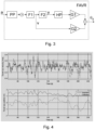
- Figure 4 illustrates time traces of a velocity estimate (top) and a position estimate (bottom) obtained by the method as defined in Fig. 3 .
- the estimated signals follow the measured signal.
- the estimated position is due to the high pass filter (HP) centred around zero.
- Figure 5 illustrates a time series of resulting pitch angle and tower top position by applying a pitch offset to the collective pitch as determined by embodiments of the present invention.
- the pitch angle is shown with a pitch offset added to the collective pitch (dotted line) and without the pitch offset added (full line). As can be seen, only a slight pitch variation is superimposed.
- a simulated tower top position is shown in a situation where tower vibrations are reduced by application of the pitch offset (dotted line) as compared to a situation where tower vibration reduction is not performed (full line).
- the bottom figure also shows a fast Fourier transform (FFT) of the tower top position.
- FFT fast Fourier transform
- the tower top position is generally reduced by application of the damping method. This is reflected in the frequency plot as the resonance at 0.1 Hz is reduced.
- FIG. 6 illustrates an example of multi-rotor turbine 61 with four nacelle modules (wind turbine module) 62 mounted to a common support structure 63.
- Each wind turbine module is a wind turbine generating entity, and may in principle be the generating part of a common single-rotor wind turbine including rotor, generator, converter, etc.
- the support structure 63 is one part of a tower structure 64 comprising parts of a tower structure in the form of support arm arrangements 65 for holding the wind turbine modules.
- the multi-rotor layout may be different from the one shown, comprising more or fewer nacelle modules, arranged in a different manner to the common support structure.
- Each nacelle module may vibrate in a fore-aft direction 60 (in and out in the paper plane).
- vibrations may be damped by application of the method described for the single rotor turbine.
- a pitch offset may be determined for each wind turbine module based on an acceleration measurement in the fore-aft direction of each wind turbine module, an accelerometer may be arranged for each wind turbine module to measure the acceleration of the associated nacelle.
- the method may be implemented for each of the wind turbine modules.
Landscapes
- Engineering & Computer Science (AREA)
- Chemical & Material Sciences (AREA)
- Life Sciences & Earth Sciences (AREA)
- Sustainable Development (AREA)
- Sustainable Energy (AREA)
- Combustion & Propulsion (AREA)
- Mechanical Engineering (AREA)
- General Engineering & Computer Science (AREA)
- Fluid Mechanics (AREA)
- Physics & Mathematics (AREA)
- Wind Motors (AREA)
- Devices For Conveying Motion By Means Of Endless Flexible Members (AREA)
- Vibration Prevention Devices (AREA)
Claims (9)
- Procédé de commande d'une éolienne, l'éolienne comprenant une structure de tour supportant une nacelle et un rotor avec un nombre de pales de rotor à calage ajustable, et un accéléromètre positionné pour mesurer un signal d'accélération de la nacelle, le procédé comprend :la détermination d'une référence de calage collectif pour les pales de rotor à calage ajustable, la référence de calage collectif étant déterminée sur la base d'une vitesse de rotor ;l'obtention du signal d'accélération dans la direction avant-arrière ;l'obtention d'un signal de position indiquant une position de la nacelle dans la direction avant-arrière comme un signal de position estimée par application en série d'une première intégration du signal d'accélération pour obtenir un signal de vitesse estimée et d'une seconde intégration du signal de vitesse pour obtenir le signal de position ;déterminer un premier signal de calage sur la base du signal de position comme la position estimée multipliée par un premier gain, le premier signal de calage étant déterminé pour réduire la vibration de nacelle ;obtenir un signal de vitesse indiquant une vitesse d'un mouvement de la nacelle comme le signal de vitesse estimé ;déterminer un second signal de calage sur la base du signal de vitesse comme la vitesse estimée multipliée par un second gain, le second signal de calage étant déterminé pour réduire la vibration de nacelle ;appliquer un signal de calage résultant aux pales de rotor à calage ajustable, le signal de calage résultant étant une somme du signal de la référence de calage collectif et du premier signal de calage et du second de calage.
- Procédé selon la revendication 1, dans lequel la référence de calage collectif est déterminée par la régulation à réaction sur la base de la minimisation d'une erreur de vitesse entre une vitesse de rotor réelle et une vitesse de rotor de référence.
- Procédé selon la revendication 1 ou 2, dans lequel le signal de calage résultant est appliqué à la pale de rotor à calage ajustable dans un mode de commande de pleine charge.
- Procédé selon l'une quelconque des revendications précédentes, dans lequel la position de la nacelle indique le positionnement de la nacelle dans la direction avant-arrière, et/ou dans lequel la vitesse du mouvement de la nacelle indique la vitesse du mouvement de la nacelle dans la direction avant-arrière.
- Procédé selon l'une quelconque des revendications précédentes, dans lequel le signal de position subit un filtrage passe-haut avant de déterminer le premier signal de calage.
- Procédé selon l'une quelconque des revendications précédentes, dans lequel une première fréquence de mode structurel de la structure de tour est dans la plage de fréquence entre 0,025 Hz et 0,3 Hz.
- Produit de programme informatique comprenant un code logiciel adapté pour commander une éolienne lorsqu'il est exécuté sur un système de traitement de données, le produit de programme informatique étant adapté pour réaliser le procédé selon l'une quelconque des revendications 1-6.
- Système de commande pour une éolienne comprenant une structure de tour supportant une nacelle et un rotor avec un nombre de pales de rotor à calage ajustable, le système de commande étant adapté pour réaliser le procédé selon l'une quelconque des revendications 1-6.
- Eolienne comprenant une structure de tour supportant une nacelle et un rotor avec un nombre de pales de rotor à calage ajustable, la structure d'éolienne comprend en outre un système de commande selon la revendication 8.
Applications Claiming Priority (2)
| Application Number | Priority Date | Filing Date | Title |
|---|---|---|---|
| DKPA201770088 | 2017-02-10 | ||
| PCT/DK2018/050018 WO2018145710A1 (fr) | 2017-02-10 | 2018-01-30 | Réduction de vibration basée sur la position d'un mouvement de nacelle |
Publications (3)
| Publication Number | Publication Date |
|---|---|
| EP3580452A1 EP3580452A1 (fr) | 2019-12-18 |
| EP3580452C0 EP3580452C0 (fr) | 2023-07-19 |
| EP3580452B1 true EP3580452B1 (fr) | 2023-07-19 |
Family
ID=61156957
Family Applications (1)
| Application Number | Title | Priority Date | Filing Date |
|---|---|---|---|
| EP18702913.7A Active EP3580452B1 (fr) | 2017-02-10 | 2018-01-30 | Réduction de vibration d'un mouvement de nacelle basée sur la position |
Country Status (5)
| Country | Link |
|---|---|
| US (1) | US11396862B2 (fr) |
| EP (1) | EP3580452B1 (fr) |
| CN (1) | CN110494648B (fr) |
| ES (1) | ES2951472T3 (fr) |
| WO (1) | WO2018145710A1 (fr) |
Families Citing this family (12)
| Publication number | Priority date | Publication date | Assignee | Title |
|---|---|---|---|---|
| ES2951472T3 (es) | 2017-02-10 | 2023-10-23 | Vestas Wind Sys As | Reducción de vibración de movimiento de góndola basada en posición |
| CN112012884B (zh) * | 2019-05-28 | 2022-08-16 | 北京金风科创风电设备有限公司 | 风力发电机组的控制方法及设备 |
| CN112696317B (zh) * | 2019-10-22 | 2025-04-15 | 通用电气可再生能源西班牙有限公司 | 用于基于集体俯仰偏移来控制风力涡轮的系统和方法 |
| GB2590388B (en) | 2019-12-13 | 2022-02-16 | Equinor Energy As | Blade pitch controller for a wind turbine |
| GB2591732C (en) * | 2019-12-20 | 2026-01-28 | Equinor Energy As | Wind turbine control |
| US11913431B2 (en) | 2020-01-06 | 2024-02-27 | Vestas Wind Systems A/S | Wind turbine oscillation detection |
| EP3919739A1 (fr) * | 2020-06-02 | 2021-12-08 | Siemens Gamesa Renewable Energy Innovation & Technology S.L. | Commande robuste d'éoliennes avec mât à très basse fréquence naturelle |
| EP4352358A1 (fr) | 2021-06-08 | 2024-04-17 | Vestas Wind Systems A/S | Détermination de l'accélération de la tête de tour d'une éolienne |
| CN113833606B (zh) * | 2021-09-29 | 2023-09-26 | 上海电气风电集团股份有限公司 | 阻尼控制方法、系统和可读存储介质 |
| WO2024083294A1 (fr) * | 2022-10-21 | 2024-04-25 | Vestas Wind Systems A/S | Commande de pas de pale de rotor d'éolienne pour une réduction de la fatigue de la tour |
| EP4677219A1 (fr) * | 2023-03-06 | 2026-01-14 | Vestas Wind Systems A/S | Estimation de vitesse dans une direction avant-arrière d'une partie supérieure d'une tour d'éolienne sur la base de charges de volet de pale |
| EP4632219A1 (fr) * | 2024-04-10 | 2025-10-15 | Nordex Energy SE & Co. KG | Procédé de fonctionnement d'une éolienne et éolienne |
Citations (9)
| Publication number | Priority date | Publication date | Assignee | Title |
|---|---|---|---|---|
| US4435647A (en) | 1982-04-02 | 1984-03-06 | United Technologies Corporation | Predicted motion wind turbine tower damping |
| US20080206051A1 (en) | 2004-02-27 | 2008-08-28 | Tsuyoshi Wakasa | Wind Turbine Generator, Active Damping Method Thereof, and Windmill Tower |
| WO2009010059A2 (fr) | 2007-07-14 | 2009-01-22 | Vestas Wind Systems A/S | Commande d'un rotor pendant un processus d'arrêt d'une éolienne |
| US20100111693A1 (en) | 2006-12-28 | 2010-05-06 | Kitchener Clark Wilson | Wind turbine damping of tower resonant motion and symmetric blade motion using estimation methods |
| WO2010060772A2 (fr) * | 2008-11-28 | 2010-06-03 | Vestas Wind Systems A/S | Stratégie de gestion pour éolienne |
| EP2784303A1 (fr) | 2013-03-27 | 2014-10-01 | Alstom Renovables España, S.L. | Procédé de fonctionnement d'une éolienne |
| WO2014191001A1 (fr) | 2013-05-30 | 2014-12-04 | Mhi Vestas Offshore Wind A/S | Limitation de l'humidité d'une éolienne flottante |
| CN104214045A (zh) | 2013-05-30 | 2014-12-17 | 成都阜特科技股份有限公司 | 双馈式变速变桨风力发电机组的独立变桨距控制方法 |
| US20160377057A1 (en) | 2013-12-09 | 2016-12-29 | Vestas Wind Systems A/S | Counteracting tower oscillations of an idling wind turbine |
Family Cites Families (11)
| Publication number | Priority date | Publication date | Assignee | Title |
|---|---|---|---|---|
| US7317260B2 (en) | 2004-05-11 | 2008-01-08 | Clipper Windpower Technology, Inc. | Wind flow estimation and tracking using tower dynamics |
| NO335851B1 (no) * | 2006-08-22 | 2015-03-09 | Hywind As | Fremgangsmåte ved vindturbininstallasjon for demping av tårnsvingninger |
| GB2466649B (en) * | 2008-12-30 | 2014-01-29 | Hywind As | Blade pitch control in a wind turbine installation |
| EP2438300A2 (fr) * | 2009-06-03 | 2012-04-11 | Vestas Wind Systems A/S | Système de commande et de contrôle de tour supporté par un moyeu pour des éoliennes |
| US8360723B2 (en) * | 2009-09-30 | 2013-01-29 | General Electric Company | Method for reducing vibrations in wind turbines and wind turbine implementing said method |
| DE102010044433A1 (de) * | 2010-09-06 | 2012-03-08 | Nordex Energy Gmbh | Verfahren zur Drehzahlregelung einer Windenergieanlage |
| US9644606B2 (en) | 2012-06-29 | 2017-05-09 | General Electric Company | Systems and methods to reduce tower oscillations in a wind turbine |
| CN103321854B (zh) * | 2013-05-29 | 2016-08-10 | 国家电网公司 | 一种风力发电机组塔架振动控制方法 |
| ES2694009T3 (es) | 2013-12-09 | 2018-12-17 | Vestas Wind Systems A/S | Método de operación de una turbina eólica |
| US9587629B2 (en) | 2014-06-30 | 2017-03-07 | General Electric Company | Methods and systems to operate a wind turbine system using a non-linear damping model |
| ES2951472T3 (es) | 2017-02-10 | 2023-10-23 | Vestas Wind Sys As | Reducción de vibración de movimiento de góndola basada en posición |
-
2018
- 2018-01-30 ES ES18702913T patent/ES2951472T3/es active Active
- 2018-01-30 US US16/484,745 patent/US11396862B2/en active Active
- 2018-01-30 EP EP18702913.7A patent/EP3580452B1/fr active Active
- 2018-01-30 WO PCT/DK2018/050018 patent/WO2018145710A1/fr not_active Ceased
- 2018-01-30 CN CN201880024194.5A patent/CN110494648B/zh active Active
Patent Citations (9)
| Publication number | Priority date | Publication date | Assignee | Title |
|---|---|---|---|---|
| US4435647A (en) | 1982-04-02 | 1984-03-06 | United Technologies Corporation | Predicted motion wind turbine tower damping |
| US20080206051A1 (en) | 2004-02-27 | 2008-08-28 | Tsuyoshi Wakasa | Wind Turbine Generator, Active Damping Method Thereof, and Windmill Tower |
| US20100111693A1 (en) | 2006-12-28 | 2010-05-06 | Kitchener Clark Wilson | Wind turbine damping of tower resonant motion and symmetric blade motion using estimation methods |
| WO2009010059A2 (fr) | 2007-07-14 | 2009-01-22 | Vestas Wind Systems A/S | Commande d'un rotor pendant un processus d'arrêt d'une éolienne |
| WO2010060772A2 (fr) * | 2008-11-28 | 2010-06-03 | Vestas Wind Systems A/S | Stratégie de gestion pour éolienne |
| EP2784303A1 (fr) | 2013-03-27 | 2014-10-01 | Alstom Renovables España, S.L. | Procédé de fonctionnement d'une éolienne |
| WO2014191001A1 (fr) | 2013-05-30 | 2014-12-04 | Mhi Vestas Offshore Wind A/S | Limitation de l'humidité d'une éolienne flottante |
| CN104214045A (zh) | 2013-05-30 | 2014-12-17 | 成都阜特科技股份有限公司 | 双馈式变速变桨风力发电机组的独立变桨距控制方法 |
| US20160377057A1 (en) | 2013-12-09 | 2016-12-29 | Vestas Wind Systems A/S | Counteracting tower oscillations of an idling wind turbine |
Non-Patent Citations (2)
| Title |
|---|
| BOSSANYI E, SAVINI B, LRIBAS M, HAU M, FISCHER B, SCHLIPF D, VAN ENGELEN T, ROSSETTI M, CARCANGIU C E: "Advanced controller research for multi-MW wind turbines in the UPWIND project", WIND ENERGY, vol. 15, 1 January 2012 (2012-01-01), pages 119 - 145, XP093247502, DOI: 10.1002/we.523 |
| COMAN S, BOLDISOR CR: "Adaptive PI controller design to control a mass-damper-spring-process", BULLETIN OF THE TRANSSILVANIA UNIVERSITY OF BRASOV, vol. 7, no. 2, 1 January 2014 (2014-01-01), pages 69 - 74, XP093247490 |
Also Published As
| Publication number | Publication date |
|---|---|
| EP3580452C0 (fr) | 2023-07-19 |
| CN110494648A (zh) | 2019-11-22 |
| WO2018145710A1 (fr) | 2018-08-16 |
| EP3580452A1 (fr) | 2019-12-18 |
| US20200011296A1 (en) | 2020-01-09 |
| CN110494648B (zh) | 2021-01-29 |
| ES2951472T3 (es) | 2023-10-23 |
| US11396862B2 (en) | 2022-07-26 |
Similar Documents
| Publication | Publication Date | Title |
|---|---|---|
| EP3580452B1 (fr) | Réduction de vibration d'un mouvement de nacelle basée sur la position | |
| CN110651120B (zh) | 基于位置的风力涡轮机的机舱运动的减振 | |
| EP3791061B1 (fr) | Système de commande de rotor pour réduire les vibrations structurelles d'une éolienne | |
| EP3976959B1 (fr) | Réduction de vibrations de chant à l'aide d'un signal de charge de pale | |
| CN112424470B (zh) | 用于控制风力涡轮机以减少机舱振动的方法和系统 | |
| EP3976960B1 (fr) | Réduction de vibrations dans le sens de la traînée à l'aide d'un signal de vibration de torsion | |
| EP3794230B1 (fr) | Procédé et système de commande d'une éolienne pour réduire la vibration de nacelle | |
| EP3167185B1 (fr) | Promotion active d'oscillations de tour d'éolienne | |
| WO2019042515A1 (fr) | Amortissement de vibration de torsion dans une éolienne à rotors multiples | |
| WO2020007431A1 (fr) | Amortissement d'oscillation d'éolienne à rotors multiples |
Legal Events
| Date | Code | Title | Description |
|---|---|---|---|
| STAA | Information on the status of an ep patent application or granted ep patent |
Free format text: STATUS: UNKNOWN |
|
| STAA | Information on the status of an ep patent application or granted ep patent |
Free format text: STATUS: THE INTERNATIONAL PUBLICATION HAS BEEN MADE |
|
| PUAI | Public reference made under article 153(3) epc to a published international application that has entered the european phase |
Free format text: ORIGINAL CODE: 0009012 |
|
| STAA | Information on the status of an ep patent application or granted ep patent |
Free format text: STATUS: REQUEST FOR EXAMINATION WAS MADE |
|
| 17P | Request for examination filed |
Effective date: 20190807 |
|
| AK | Designated contracting states |
Kind code of ref document: A1 Designated state(s): AL AT BE BG CH CY CZ DE DK EE ES FI FR GB GR HR HU IE IS IT LI LT LU LV MC MK MT NL NO PL PT RO RS SE SI SK SM TR |
|
| STAA | Information on the status of an ep patent application or granted ep patent |
Free format text: STATUS: EXAMINATION IS IN PROGRESS |
|
| 17Q | First examination report despatched |
Effective date: 20220207 |
|
| GRAP | Despatch of communication of intention to grant a patent |
Free format text: ORIGINAL CODE: EPIDOSNIGR1 |
|
| STAA | Information on the status of an ep patent application or granted ep patent |
Free format text: STATUS: GRANT OF PATENT IS INTENDED |
|
| INTG | Intention to grant announced |
Effective date: 20230420 |
|
| GRAS | Grant fee paid |
Free format text: ORIGINAL CODE: EPIDOSNIGR3 |
|
| GRAA | (expected) grant |
Free format text: ORIGINAL CODE: 0009210 |
|
| STAA | Information on the status of an ep patent application or granted ep patent |
Free format text: STATUS: THE PATENT HAS BEEN GRANTED |
|
| AK | Designated contracting states |
Kind code of ref document: B1 Designated state(s): AL AT BE BG CH CY CZ DE DK EE ES FI FR GB GR HR HU IE IS IT LI LT LU LV MC MK MT NL NO PL PT RO RS SE SI SK SM TR |
|
| REG | Reference to a national code |
Ref country code: GB Ref legal event code: FG4D |
|
| REG | Reference to a national code |
Ref country code: CH Ref legal event code: EP |
|
| REG | Reference to a national code |
Ref country code: DE Ref legal event code: R096 Ref document number: 602018053554 Country of ref document: DE |
|
| REG | Reference to a national code |
Ref country code: IE Ref legal event code: FG4D |
|
| U01 | Request for unitary effect filed |
Effective date: 20230814 |
|
| U07 | Unitary effect registered |
Designated state(s): AT BE BG DE DK EE FI FR IT LT LU LV MT NL PT SE SI Effective date: 20230821 |
|
| REG | Reference to a national code |
Ref country code: ES Ref legal event code: FG2A Ref document number: 2951472 Country of ref document: ES Kind code of ref document: T3 Effective date: 20231023 |
|
| REG | Reference to a national code |
Ref country code: LT Ref legal event code: MG9D |
|
| PG25 | Lapsed in a contracting state [announced via postgrant information from national office to epo] |
Ref country code: GR Free format text: LAPSE BECAUSE OF FAILURE TO SUBMIT A TRANSLATION OF THE DESCRIPTION OR TO PAY THE FEE WITHIN THE PRESCRIBED TIME-LIMIT Effective date: 20231020 |
|
| PG25 | Lapsed in a contracting state [announced via postgrant information from national office to epo] |
Ref country code: IS Free format text: LAPSE BECAUSE OF FAILURE TO SUBMIT A TRANSLATION OF THE DESCRIPTION OR TO PAY THE FEE WITHIN THE PRESCRIBED TIME-LIMIT Effective date: 20231119 |
|
| PG25 | Lapsed in a contracting state [announced via postgrant information from national office to epo] |
Ref country code: RS Free format text: LAPSE BECAUSE OF FAILURE TO SUBMIT A TRANSLATION OF THE DESCRIPTION OR TO PAY THE FEE WITHIN THE PRESCRIBED TIME-LIMIT Effective date: 20230719 Ref country code: NO Free format text: LAPSE BECAUSE OF FAILURE TO SUBMIT A TRANSLATION OF THE DESCRIPTION OR TO PAY THE FEE WITHIN THE PRESCRIBED TIME-LIMIT Effective date: 20231019 Ref country code: IS Free format text: LAPSE BECAUSE OF FAILURE TO SUBMIT A TRANSLATION OF THE DESCRIPTION OR TO PAY THE FEE WITHIN THE PRESCRIBED TIME-LIMIT Effective date: 20231119 Ref country code: HR Free format text: LAPSE BECAUSE OF FAILURE TO SUBMIT A TRANSLATION OF THE DESCRIPTION OR TO PAY THE FEE WITHIN THE PRESCRIBED TIME-LIMIT Effective date: 20230719 Ref country code: GR Free format text: LAPSE BECAUSE OF FAILURE TO SUBMIT A TRANSLATION OF THE DESCRIPTION OR TO PAY THE FEE WITHIN THE PRESCRIBED TIME-LIMIT Effective date: 20231020 |
|
| U20 | Renewal fee for the european patent with unitary effect paid |
Year of fee payment: 7 Effective date: 20240125 |
|
| PG25 | Lapsed in a contracting state [announced via postgrant information from national office to epo] |
Ref country code: PL Free format text: LAPSE BECAUSE OF FAILURE TO SUBMIT A TRANSLATION OF THE DESCRIPTION OR TO PAY THE FEE WITHIN THE PRESCRIBED TIME-LIMIT Effective date: 20230719 |
|
| REG | Reference to a national code |
Ref country code: DE Ref legal event code: R026 Ref document number: 602018053554 Country of ref document: DE |
|
| PLBI | Opposition filed |
Free format text: ORIGINAL CODE: 0009260 |
|
| PLAB | Opposition data, opponent's data or that of the opponent's representative modified |
Free format text: ORIGINAL CODE: 0009299OPPO |
|
| PG25 | Lapsed in a contracting state [announced via postgrant information from national office to epo] |
Ref country code: SM Free format text: LAPSE BECAUSE OF FAILURE TO SUBMIT A TRANSLATION OF THE DESCRIPTION OR TO PAY THE FEE WITHIN THE PRESCRIBED TIME-LIMIT Effective date: 20230719 Ref country code: RO Free format text: LAPSE BECAUSE OF FAILURE TO SUBMIT A TRANSLATION OF THE DESCRIPTION OR TO PAY THE FEE WITHIN THE PRESCRIBED TIME-LIMIT Effective date: 20230719 Ref country code: CZ Free format text: LAPSE BECAUSE OF FAILURE TO SUBMIT A TRANSLATION OF THE DESCRIPTION OR TO PAY THE FEE WITHIN THE PRESCRIBED TIME-LIMIT Effective date: 20230719 Ref country code: SK Free format text: LAPSE BECAUSE OF FAILURE TO SUBMIT A TRANSLATION OF THE DESCRIPTION OR TO PAY THE FEE WITHIN THE PRESCRIBED TIME-LIMIT Effective date: 20230719 |
|
| 26 | Opposition filed |
Opponent name: SIEMENS GAMESA RENEWABLE ENERGY GMBH & CO. KG Effective date: 20240418 |
|
| R26 | Opposition filed (corrected) |
Opponent name: SIEMENS GAMESA RENEWABLE ENERGY GMBH & CO. KG Effective date: 20240418 |
|
| PLAX | Notice of opposition and request to file observation + time limit sent |
Free format text: ORIGINAL CODE: EPIDOSNOBS2 |
|
| PG25 | Lapsed in a contracting state [announced via postgrant information from national office to epo] |
Ref country code: MC Free format text: LAPSE BECAUSE OF FAILURE TO SUBMIT A TRANSLATION OF THE DESCRIPTION OR TO PAY THE FEE WITHIN THE PRESCRIBED TIME-LIMIT Effective date: 20230719 |
|
| PG25 | Lapsed in a contracting state [announced via postgrant information from national office to epo] |
Ref country code: MC Free format text: LAPSE BECAUSE OF FAILURE TO SUBMIT A TRANSLATION OF THE DESCRIPTION OR TO PAY THE FEE WITHIN THE PRESCRIBED TIME-LIMIT Effective date: 20230719 |
|
| REG | Reference to a national code |
Ref country code: CH Ref legal event code: PL |
|
| PLBB | Reply of patent proprietor to notice(s) of opposition received |
Free format text: ORIGINAL CODE: EPIDOSNOBS3 |
|
| PG25 | Lapsed in a contracting state [announced via postgrant information from national office to epo] |
Ref country code: CH Free format text: LAPSE BECAUSE OF NON-PAYMENT OF DUE FEES Effective date: 20240131 |
|
| PG25 | Lapsed in a contracting state [announced via postgrant information from national office to epo] |
Ref country code: CH Free format text: LAPSE BECAUSE OF NON-PAYMENT OF DUE FEES Effective date: 20240131 |
|
| PG25 | Lapsed in a contracting state [announced via postgrant information from national office to epo] |
Ref country code: IE Free format text: LAPSE BECAUSE OF NON-PAYMENT OF DUE FEES Effective date: 20240130 |
|
| PG25 | Lapsed in a contracting state [announced via postgrant information from national office to epo] |
Ref country code: IE Free format text: LAPSE BECAUSE OF NON-PAYMENT OF DUE FEES Effective date: 20240130 |
|
| U20 | Renewal fee for the european patent with unitary effect paid |
Year of fee payment: 8 Effective date: 20250127 |
|
| PGFP | Annual fee paid to national office [announced via postgrant information from national office to epo] |
Ref country code: ES Payment date: 20250210 Year of fee payment: 8 |
|
| PGFP | Annual fee paid to national office [announced via postgrant information from national office to epo] |
Ref country code: GB Payment date: 20250121 Year of fee payment: 8 |
|
| PLAB | Opposition data, opponent's data or that of the opponent's representative modified |
Free format text: ORIGINAL CODE: 0009299OPPO |
|
| PG25 | Lapsed in a contracting state [announced via postgrant information from national office to epo] |
Ref country code: CY Free format text: LAPSE BECAUSE OF FAILURE TO SUBMIT A TRANSLATION OF THE DESCRIPTION OR TO PAY THE FEE WITHIN THE PRESCRIBED TIME-LIMIT; INVALID AB INITIO Effective date: 20180130 |
|
| R26 | Opposition filed (corrected) |
Opponent name: SIEMENS GAMESA RENEWABLE ENERGY DEUTSCHLAND GMBH Effective date: 20240418 |
|
| PG25 | Lapsed in a contracting state [announced via postgrant information from national office to epo] |
Ref country code: HU Free format text: LAPSE BECAUSE OF FAILURE TO SUBMIT A TRANSLATION OF THE DESCRIPTION OR TO PAY THE FEE WITHIN THE PRESCRIBED TIME-LIMIT; INVALID AB INITIO Effective date: 20180130 |
|
| PG25 | Lapsed in a contracting state [announced via postgrant information from national office to epo] |
Ref country code: TR Free format text: LAPSE BECAUSE OF FAILURE TO SUBMIT A TRANSLATION OF THE DESCRIPTION OR TO PAY THE FEE WITHIN THE PRESCRIBED TIME-LIMIT Effective date: 20230719 |
|
| PLCK | Communication despatched that opposition was rejected |
Free format text: ORIGINAL CODE: EPIDOSNREJ1 |
|
| U20 | Renewal fee for the european patent with unitary effect paid |
Year of fee payment: 9 Effective date: 20260126 |
|
| PLBN | Opposition rejected |
Free format text: ORIGINAL CODE: 0009273 |
|
| STAA | Information on the status of an ep patent application or granted ep patent |
Free format text: STATUS: OPPOSITION REJECTED |