EP3580410B1 - Cover lift system for a spa - Google Patents
Cover lift system for a spa Download PDFInfo
- Publication number
- EP3580410B1 EP3580410B1 EP18751582.0A EP18751582A EP3580410B1 EP 3580410 B1 EP3580410 B1 EP 3580410B1 EP 18751582 A EP18751582 A EP 18751582A EP 3580410 B1 EP3580410 B1 EP 3580410B1
- Authority
- EP
- European Patent Office
- Prior art keywords
- cover
- lift system
- spa
- coupling member
- cover lift
- Prior art date
- Legal status (The legal status is an assumption and is not a legal conclusion. Google has not performed a legal analysis and makes no representation as to the accuracy of the status listed.)
- Active
Links
Images






Classifications
-
- E—FIXED CONSTRUCTIONS
- E04—BUILDING
- E04H—BUILDINGS OR LIKE STRUCTURES FOR PARTICULAR PURPOSES; SWIMMING OR SPLASH BATHS OR POOLS; MASTS; FENCING; TENTS OR CANOPIES, IN GENERAL
- E04H4/00—Swimming or splash baths or pools
- E04H4/06—Safety devices; Coverings for baths
- E04H4/08—Coverings consisting of rigid elements, e.g. coverings composed of separate or connected elements
- E04H4/084—Coverings consisting of rigid elements, e.g. coverings composed of separate or connected elements with lifting mechanism
-
- F—MECHANICAL ENGINEERING; LIGHTING; HEATING; WEAPONS; BLASTING
- F16—ENGINEERING ELEMENTS AND UNITS; GENERAL MEASURES FOR PRODUCING AND MAINTAINING EFFECTIVE FUNCTIONING OF MACHINES OR INSTALLATIONS; THERMAL INSULATION IN GENERAL
- F16B—DEVICES FOR FASTENING OR SECURING CONSTRUCTIONAL ELEMENTS OR MACHINE PARTS TOGETHER, e.g. NAILS, BOLTS, CIRCLIPS, CLAMPS, CLIPS OR WEDGES; JOINTS OR JOINTING
- F16B7/00—Connections of rods or tubes, e.g. of non-circular section, mutually, including resilient connections
- F16B7/04—Clamping or clipping connections
-
- F—MECHANICAL ENGINEERING; LIGHTING; HEATING; WEAPONS; BLASTING
- F16—ENGINEERING ELEMENTS AND UNITS; GENERAL MEASURES FOR PRODUCING AND MAINTAINING EFFECTIVE FUNCTIONING OF MACHINES OR INSTALLATIONS; THERMAL INSULATION IN GENERAL
- F16B—DEVICES FOR FASTENING OR SECURING CONSTRUCTIONAL ELEMENTS OR MACHINE PARTS TOGETHER, e.g. NAILS, BOLTS, CIRCLIPS, CLAMPS, CLIPS OR WEDGES; JOINTS OR JOINTING
- F16B7/00—Connections of rods or tubes, e.g. of non-circular section, mutually, including resilient connections
- F16B7/18—Connections of rods or tubes, e.g. of non-circular section, mutually, including resilient connections using screw-thread elements
- F16B7/182—Connections of rods or tubes, e.g. of non-circular section, mutually, including resilient connections using screw-thread elements for coaxial connections of two rods or tubes
-
- F—MECHANICAL ENGINEERING; LIGHTING; HEATING; WEAPONS; BLASTING
- F16—ENGINEERING ELEMENTS AND UNITS; GENERAL MEASURES FOR PRODUCING AND MAINTAINING EFFECTIVE FUNCTIONING OF MACHINES OR INSTALLATIONS; THERMAL INSULATION IN GENERAL
- F16D—COUPLINGS FOR TRANSMITTING ROTATION; CLUTCHES; BRAKES
- F16D7/00—Slip couplings, e.g. slipping on overload, for absorbing shock
- F16D7/02—Slip couplings, e.g. slipping on overload, for absorbing shock of the friction type
- F16D7/024—Slip couplings, e.g. slipping on overload, for absorbing shock of the friction type with axially applied torque limiting friction surfaces
- F16D7/025—Slip couplings, e.g. slipping on overload, for absorbing shock of the friction type with axially applied torque limiting friction surfaces with flat clutching surfaces, e.g. discs
- F16D7/027—Slip couplings, e.g. slipping on overload, for absorbing shock of the friction type with axially applied torque limiting friction surfaces with flat clutching surfaces, e.g. discs with multiple lamellae
-
- F—MECHANICAL ENGINEERING; LIGHTING; HEATING; WEAPONS; BLASTING
- F16—ENGINEERING ELEMENTS AND UNITS; GENERAL MEASURES FOR PRODUCING AND MAINTAINING EFFECTIVE FUNCTIONING OF MACHINES OR INSTALLATIONS; THERMAL INSULATION IN GENERAL
- F16H—GEARING
- F16H21/00—Gearings comprising primarily only links or levers, with or without slides
- F16H21/10—Gearings comprising primarily only links or levers, with or without slides all movement being in, or parallel to, a single plane
- F16H21/44—Gearings comprising primarily only links or levers, with or without slides all movement being in, or parallel to, a single plane for conveying or interconverting oscillating or reciprocating motions
-
- F—MECHANICAL ENGINEERING; LIGHTING; HEATING; WEAPONS; BLASTING
- F16—ENGINEERING ELEMENTS AND UNITS; GENERAL MEASURES FOR PRODUCING AND MAINTAINING EFFECTIVE FUNCTIONING OF MACHINES OR INSTALLATIONS; THERMAL INSULATION IN GENERAL
- F16H—GEARING
- F16H25/00—Gearings comprising primarily only cams, cam-followers and screw-and-nut mechanisms
- F16H25/18—Gearings comprising primarily only cams, cam-followers and screw-and-nut mechanisms for conveying or interconverting oscillating or reciprocating motions
- F16H25/20—Screw mechanisms
-
- F—MECHANICAL ENGINEERING; LIGHTING; HEATING; WEAPONS; BLASTING
- F16—ENGINEERING ELEMENTS AND UNITS; GENERAL MEASURES FOR PRODUCING AND MAINTAINING EFFECTIVE FUNCTIONING OF MACHINES OR INSTALLATIONS; THERMAL INSULATION IN GENERAL
- F16B—DEVICES FOR FASTENING OR SECURING CONSTRUCTIONAL ELEMENTS OR MACHINE PARTS TOGETHER, e.g. NAILS, BOLTS, CIRCLIPS, CLAMPS, CLIPS OR WEDGES; JOINTS OR JOINTING
- F16B33/00—Features common to bolt and nut
- F16B33/002—Means for preventing rotation of screw-threaded elements
-
- F—MECHANICAL ENGINEERING; LIGHTING; HEATING; WEAPONS; BLASTING
- F16—ENGINEERING ELEMENTS AND UNITS; GENERAL MEASURES FOR PRODUCING AND MAINTAINING EFFECTIVE FUNCTIONING OF MACHINES OR INSTALLATIONS; THERMAL INSULATION IN GENERAL
- F16B—DEVICES FOR FASTENING OR SECURING CONSTRUCTIONAL ELEMENTS OR MACHINE PARTS TOGETHER, e.g. NAILS, BOLTS, CIRCLIPS, CLAMPS, CLIPS OR WEDGES; JOINTS OR JOINTING
- F16B7/00—Connections of rods or tubes, e.g. of non-circular section, mutually, including resilient connections
- F16B7/10—Telescoping systems
- F16B7/14—Telescoping systems locking in intermediate non-discrete positions
-
- F—MECHANICAL ENGINEERING; LIGHTING; HEATING; WEAPONS; BLASTING
- F16—ENGINEERING ELEMENTS AND UNITS; GENERAL MEASURES FOR PRODUCING AND MAINTAINING EFFECTIVE FUNCTIONING OF MACHINES OR INSTALLATIONS; THERMAL INSULATION IN GENERAL
- F16D—COUPLINGS FOR TRANSMITTING ROTATION; CLUTCHES; BRAKES
- F16D7/00—Slip couplings, e.g. slipping on overload, for absorbing shock
- F16D7/005—Slip couplings, e.g. slipping on overload, for absorbing shock the torque being transmitted and limited by rolling friction, e.g. ball bearings axially loaded
-
- F—MECHANICAL ENGINEERING; LIGHTING; HEATING; WEAPONS; BLASTING
- F16—ENGINEERING ELEMENTS AND UNITS; GENERAL MEASURES FOR PRODUCING AND MAINTAINING EFFECTIVE FUNCTIONING OF MACHINES OR INSTALLATIONS; THERMAL INSULATION IN GENERAL
- F16H—GEARING
- F16H19/00—Gearings comprising essentially only toothed gears or friction members and not capable of conveying indefinitely-continuing rotary motion
- F16H19/02—Gearings comprising essentially only toothed gears or friction members and not capable of conveying indefinitely-continuing rotary motion for interconverting rotary or oscillating motion and reciprocating motion
- F16H19/06—Gearings comprising essentially only toothed gears or friction members and not capable of conveying indefinitely-continuing rotary motion for interconverting rotary or oscillating motion and reciprocating motion comprising flexible members, e.g. an endless flexible member
- F16H19/0622—Gearings comprising essentially only toothed gears or friction members and not capable of conveying indefinitely-continuing rotary motion for interconverting rotary or oscillating motion and reciprocating motion comprising flexible members, e.g. an endless flexible member for converting reciprocating movement into oscillating movement and vice versa, the reciprocating movement is perpendicular to the axis of oscillation
-
- F—MECHANICAL ENGINEERING; LIGHTING; HEATING; WEAPONS; BLASTING
- F16—ENGINEERING ELEMENTS AND UNITS; GENERAL MEASURES FOR PRODUCING AND MAINTAINING EFFECTIVE FUNCTIONING OF MACHINES OR INSTALLATIONS; THERMAL INSULATION IN GENERAL
- F16H—GEARING
- F16H19/00—Gearings comprising essentially only toothed gears or friction members and not capable of conveying indefinitely-continuing rotary motion
- F16H19/02—Gearings comprising essentially only toothed gears or friction members and not capable of conveying indefinitely-continuing rotary motion for interconverting rotary or oscillating motion and reciprocating motion
- F16H19/06—Gearings comprising essentially only toothed gears or friction members and not capable of conveying indefinitely-continuing rotary motion for interconverting rotary or oscillating motion and reciprocating motion comprising flexible members, e.g. an endless flexible member
- F16H2019/0613—Gearings comprising essentially only toothed gears or friction members and not capable of conveying indefinitely-continuing rotary motion for interconverting rotary or oscillating motion and reciprocating motion comprising flexible members, e.g. an endless flexible member the flexible member being a toothed belt or chain engaging a rack
Definitions
- the present invention relates generally to spas and, more particularly, to manual and automated mechanisms for opening and closing a spa hard cover.
- US 2006/0053543 A1 discloses a water recreational apparatus having a water basin combination, a cover for covering the water basin combination and a cover removal combination wherein the cover removal combination includes a cover attachment arm which is rotatably attached to the exterior of the water basin combination.
- US 5,566,403 discloses a spa cover lifting apparatus which can be adjusted to accommodate spa covers of different sizes and which can be attached to the spa cover without damaging said spa cover or requiring special fastening means.
- Spas also commonly known as hot tubs, are popular fixtures that are used in many homes. They generally include a deep, vacuum formed tub having a smooth acrylic liner that is filled with heated water and which is used for soaking and relaxation. Spas typically include water jets for massage purposes.
- the acrylic liner is formed into shapes that provide a variety of seating arrangements within the tub.
- Each seat is usually equipped with hydrotherapy jets that allow a pressurized flow of water to be directed at various parts of a user's body.
- the water flow may be aerated for additional effect, and some or all of the jets may also automatically move or rotate, causing the changing pressure of the water on the body to provide a massage like effect.
- spas/hot tubs are located outdoors, they are often equipped with covers for enclosing the tub when not in use. These covers help prevent dirt, leaves and other debris from entering the water, and provide a safety function by preventing children and animals from falling into the water. Moreover, spa covers are often insulated so as to limit heat loss from the water when the spa is not in use, for purposes of energy efficiency and readiness of use.
- Typical hard covers generally consist of a hollow plastic shell that can be filled with an insulating foam. These covers typically include internal ribs or columns (also referred to as “kiss offs”) that extend between the top shell member and the bottom shell member of the cover to provide structural rigidity and support to the cover. These kiss-offs, while providing rigidity, can degrade the overall insulative benefits of the cover by providing a conductive means for heat to escape the spa to atmosphere.
- typical hard covers for spas may be formed using a variety of molding methods, such as through rotational molding and blow molding, as well as vacuum forming. These hard covers typically require some sort of lift mechanism to remove them from the spa. Soft covers can be manually slid off the spa and manually slid back on with significant effort. Hard covers require an assist mechanism to remove them due to the hard nature of the cover material and the increased weight over a soft cover.
- Existing cover lifter systems can suffer from water infiltration issues, difficulty in installation, much greater difficulty in servicing in the field do to mechanisms being installed from within the spa cabinet interior, and non-reproducibility of the lifter positioning system due to less than optimum fixturing.
- a cover lift system for a spa includes a lifter handle having an upper arm and a lower arm telescopically connected to the upper arm, the upper arm being configured for operative connection to a cover of a spa, and the lower arm being configured for pivotal connection to a base of the spa, and an adjuster mechanism associated with the lifter handle for selectively adjusting a length of the lifter handle to allow for use of the lifter handle with spas of varying sizes.
- the cover lift system further comprises a breakaway mechanism configured to limit an amount of torque seen by the lifter handle during a covering or uncovering operation.
- the inventive cover lift system as described in the claims is characterized by a breakaway mechanism configured to limit an amount of torque seen by a lifter handle during a covering or uncovering operation.
- Other embodiments described in the figures are only to be seen in an illustrative way.
- the cover lift system 10 includes a lifter handle 12 having a generally tubular first, upper arm 14 and a generally tubular, second lower arm 16 telescopically received by the upper arm 14.
- the upper arm 14 is generally L-shaped and includes a hollow connector member 18 that extends generally perpendicularly from an upper end of the upper arm 14, which is configured to facilitate the attachment of a crossbar 20 of the cover lift system 10 to the upper arm 14 in the manner discussed hereinafter.
- the lower arm 16 is generally L-shaped and has a hollow connector member 22 that extends generally perpendicularly from a lower end of the lower arm 16, which is configured to facilitate coupling of a lift-assist mechanism of the cover lift system 10 to the lower arm 16, in the manner discussed hereinafter.
- the lifter handle 12 includes an adjuster mechanism 24 for selectively adjusting a length of lifter handle 12 and, in particular, a distance, d, between the connector member 18 of the upper arm 14 and the connector member 22 of the lower arm 16.
- the adjuster mechanism 24 is selectively actuatable to either draw the connector members 18, 22 towards one another to shorten the distance, d, or to move the connector members 18, 22 away from one another to lengthen the distance, d.
- the adjuster mechanism 24 is a linear actuator such as, for example, a leadscrew.
- the adjuster mechanism 24 may include a leadscrew 26 mounted in fixed longitudinal position within the hollow upper arm 14 via fixing member 28.
- the leadscrew 26 has a drive head 30 configured for mating coupling with a hex socket (not shown) that enables the leadscrew 26 to be rotated within the upper arm 14 and fixing member 28.
- a nut 32 Within the upper end of the lower arm 16 is fixedly mounted a nut 32 having a threaded bore 34 for threadedly receiving a distal end 36 of the leadscrew 26.
- a socket (not shown) may be inserted into an open, upper end 38 of the upper arm 14 and engaged with the drive head 30 of the leadscrew 26 to rotate the leadscrew 26 while the nut 32 within the lower arm 16 remains stationary.
- the nut 32 is either drawn up the leadscrew towards the head 28, thereby drawing the lower arm 16 further into the upper arm 14 and decreasing the distance, d, or advanced towards the distal end 36 of the leadscrew 26, thereby extending the lower arm 16 from the upper arm 14 and increasing the distance, d.
- adjuster mechanism 24 is shown and described herein as taking the form of a leadscrew, other types of linear actuators known in the art may also be utilized without departing from the broader aspects of the invention.
- the adjuster mechanism 24 allows for the selective adjustment of the distance, d , between the connector member 18 of the upper arm 14 and the connector member 22 of the lower arm 16, enabling the cover lift system 10 to be utilized with a range of spa sizes.
- the hollow connector member 18 of the upper arm 14 contains a first mechanical coupling member 40 fixedly mounted therein, which is configured to matingly engage a corresponding second mechanical coupling member 42 fixedly mounted within the crossbar 20.
- FIGS. 6 and 7 illustrate the first coupling member mounted within the hollow connector member 18 of the upper arm 14.
- the respective coupling members 40, 42 may have a shape and size that corresponds to the shape and size of the interior of the hollow connector member 18 of the upper arm 14 and the crossbar 20, respectively.
- the coupling members 40, 42 may be substantially cylindrical in shape.
- One of the coupling members may include a key 44 configured to be received in a corresponding slot 46 of the coupling member 40 of the upper arm 14 to connect the crossbar 20 to the upper arm 14 of the lifter handle 12.
- Bores 48, 50 may extend through the coupling members 40, 42, one or both of which may be threaded. The engagement of the key 44 within the slot 46 prevents relative rotation of the crossbar 20 with respect to the hollow connector member 18 so that a rotational covering or uncovering force can be transmitted from the lifter handle 12 to the crossbar 20 (and ultimately to a cover member), as discussed hereinafter.
- the hollow connector member 22 of the lower arm 16 contains a third mechanical coupling member 52 fixedly mounted therein, which is configured to matingly engage a shaft insert 54 of a lifter mechanism (and shaft 55 thereof), as described in detail hereinafter.
- the coupling member 52 and shaft insert 54 may be substantially cylindrical in shape.
- one of the coupling member 52 and shaft insert 54 e.g., the shaft insert 54 in FIG. 10
- This stepped key 56 is configured to be received in a correspondingly shaped stepped slot 58 formed in an end of the other of the coupling member 52 and the shaft insert 54 (e.g. the coupling member 52 in FIG. 11 ). Bores 60, 62 may extend through the coupling member 52 and shaft insert 54, one or both of which may be threaded.
- the geometry of the interfaces namely, the stepped key 56 and corresponding keyway or slot 58
- FIG. 12 illustrates how a successful mating and interlocking between the coupling member 52 and shaft insert 54 can be achieved even with a substantial misalignment between the two parts.
- This feature not only makes it very easy to assemble these parts during manufacturing, but it allows for servicing in the field without the necessity of removing the sides of the spa.
- the lifter mechanism (not shown) is loaded with an air spring that causes it to rotate about 18 degrees out of alignment with the lifter handle 12 when the cover is lying flat atop the spa.
- This coupling design allows the non-aligned coupling member 52 and shaft insert 54 to be mated together and pulled into alignment simply by tightening a bolt that extends through both parts.
- the cover lift system 10 also includes a generally planar mounting bracket 64 having a plurality of apertures 66 through which fasteners may be inserted to couple the cover lift system 10 to a frame of a spa.
- the mounting bracket 64 may be mounted to an upright 68 or corner strut of a frame of a spa.
- the shaft insert 54 which is mated with the coupling 52 within the connector member 22 of the lower arm 16, extends through an aperture 70 in the mounting bracket 64 and through the frame upright 68.
- the end of the shaft insert 54 is configured for operative connection to the upper end of a lift assist mechanism (not shown), such as a gas spring, that provides an assisting force for a covering and/or uncovering operation.
- the cover lift system 10 further includes a pivot mechanism 72 operatively connected to a lower end of the mounting bracket 64 on the inside surface thereof and which extends though the frame upright 68 to receive a lower end of the lift assist mechanism (e.g., a gas spring).
- FIGS. 13-15 more clearly show the configuration of the pivot mechanism 72.
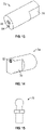
- the pivot mechanism 72 includes a ball stud holder 74 and a ball stud 76.
- the ball stud holder 74 is generally cylindrical in shape and has a pair of opposed wrenching flats 78 on one end thereof.
- the ball stud holder 74 also includes a threaded center bolt hole 80 that is configured to receive a bolt for attaching the ball stud holder 74 to the mounting bracket 64 using a bolt, and a threaded aperture 82 on the end with the wrenching flats 78 for threadedly receiving a correspondingly threaded portion of the ball stud 76. As illustrated in FIG. 14 , the threaded aperture 82 for mounting the ball stud 76 is offset from a central axis of the ball stud holder 74.
- the pivot mechanism 72 holds the lower end of the lift assist mechanism (e.g., the gas spring).
- the offset of the ball stud 76 from the central axis of the ball stud holder 74 allows the ball stud 76 to be rotated out of position around the center bolt (not shown) that is received through the center bolt hole 80.
- the lift assist mechanism can then be attached by hand to the ball stud 76 with little effort.
- a wrench can then be used to engage the wrenching flats 78 to rotate the ball stud into position, exerting a compression load on the gas spring of the lift assist mechanism.
- FIGS. 16 and 17 illustrate the cover lift system 10 installed within a spa 100.
- spa 100 incudes a pair of cover lift systems 10 for covering and uncovering first and second cover members 102, 104, respectively.
- each cover lift system 10 is attached to the outside surface of the frame uprights 68 of the frame of the spa 100.
- the crossbars extend though the cover member 102, 104 in order to transmit rotational movement of the lifter handle 12 to the cover members 102, 104, to remove the cover members 102, 104 from atop the spa during an uncovering operation, and to replace the cover members 102, 104 atop the spa during a covering operation.
- a gas spring mounted on the interior side of the bracket 64 provides a lift-assist force for both an uncovering and covering operation.
- the lift-assist mechanism exerts a generally upward force on the cover member.
- a user grasps the lifter handle 12 and, in particular, the upper arm 14 thereof, and rotates the lifter handle 12 about a horizontal axis that extends through the connector member 22 of the lower arm 16. This rotational force is transmitted through the lifter handle 12 and the crossbar 20 that extends through the cover member, causing the cover member to slide from atop the spa to an uncovered position.
- the cover lift system 10 is configured such that the brackets 64 and other components thereof are hidden under the spa cabinet side panels (which are removed in FIGS. 16 and 17 ) during use.
- the cover lift system 10 can be easily installed and serviced in the field simply by removing the side panels.
- a linear actuator assembly 200 that can be used to automatically open and close the spa cover members 102, 104 is shown (instead of manual operation).
- the linear actuator assembly 200 mounts internally to the spa frame and connects to the cover lifter system 10 described above.
- the electrically driven linear actuator drives a chain 202 that rotates the lifter handle 12.
- This automated lift assembly can be chain driven from a linear actuator 204, as shown, or can be linkage driven with or without the chain with simple linkages such as a crank rocker configuration to rotate the lifter handle 12 and open the spa cover.
- the linear actuator assembly 200 may include a friction plate type torque limiter 210 used for breakaway safety.
- an automated lifter mechanism 300 may alternatively use mechanical linkages 302, 304 connecting the linear actuator 304 with the disk 306 for rotatably driving the disk (and thus lifter handle 12). As shown in FIGS. 23 and 24 , this design may incorporate a ball/spring torque limiter 310 for use as a breakaway safety mechanism.
- the torque limiting breakaway mechanism functions to release the drive mechanism from the cover when resistance to opening or closing is encountered by people or objects.
- the toque limiting breakaway mechanism is configured to decouples the drive mechanism from the cover when a person lifts up on the cover with nominative and sufficient force to break it free in an emergency or out of power situation where the spa cover needs to be opened.
- the torque limiting breakaway mechanism will release the drive mechanism from the cover and will be fully restored to normal operating conditions when the cover is recycled through a normal opening and closing cycle.
Landscapes
- Engineering & Computer Science (AREA)
- General Engineering & Computer Science (AREA)
- Mechanical Engineering (AREA)
- Architecture (AREA)
- Civil Engineering (AREA)
- Structural Engineering (AREA)
- Invalid Beds And Related Equipment (AREA)
- Curtains And Furnishings For Windows Or Doors (AREA)
- Rehabilitation Tools (AREA)
- Devices For Medical Bathing And Washing (AREA)
Description
- The present invention relates generally to spas and, more particularly, to manual and automated mechanisms for opening and closing a spa hard cover.
-
US 2006/0053543 A1 discloses a water recreational apparatus having a water basin combination, a cover for covering the water basin combination and a cover removal combination wherein the cover removal combination includes a cover attachment arm which is rotatably attached to the exterior of the water basin combination. -
US 5,566,403 discloses a spa cover lifting apparatus which can be adjusted to accommodate spa covers of different sizes and which can be attached to the spa cover without damaging said spa cover or requiring special fastening means. - Spas, also commonly known as hot tubs, are popular fixtures that are used in many homes. They generally include a deep, vacuum formed tub having a smooth acrylic liner that is filled with heated water and which is used for soaking and relaxation. Spas typically include water jets for massage purposes.
- Typically, the acrylic liner is formed into shapes that provide a variety of seating arrangements within the tub. Each seat is usually equipped with hydrotherapy jets that allow a pressurized flow of water to be directed at various parts of a user's body. The water flow may be aerated for additional effect, and some or all of the jets may also automatically move or rotate, causing the changing pressure of the water on the body to provide a massage like effect.
- Because many spas/hot tubs are located outdoors, they are often equipped with covers for enclosing the tub when not in use. These covers help prevent dirt, leaves and other debris from entering the water, and provide a safety function by preventing children and animals from falling into the water. Moreover, spa covers are often insulated so as to limit heat loss from the water when the spa is not in use, for purposes of energy efficiency and readiness of use.
- Both soft and hard covers are known in the art. Typical hard covers generally consist of a hollow plastic shell that can be filled with an insulating foam. These covers typically include internal ribs or columns (also referred to as "kiss offs") that extend between the top shell member and the bottom shell member of the cover to provide structural rigidity and support to the cover. These kiss-offs, while providing rigidity, can degrade the overall insulative benefits of the cover by providing a conductive means for heat to escape the spa to atmosphere.
- In connection with the above, typical hard covers for spas may be formed using a variety of molding methods, such as through rotational molding and blow molding, as well as vacuum forming. These hard covers typically require some sort of lift mechanism to remove them from the spa. Soft covers can be manually slid off the spa and manually slid back on with significant effort. Hard covers require an assist mechanism to remove them due to the hard nature of the cover material and the increased weight over a soft cover. Existing cover lifter systems can suffer from water infiltration issues, difficulty in installation, much greater difficulty in servicing in the field do to mechanisms being installed from within the spa cabinet interior, and non-reproducibility of the lifter positioning system due to less than optimum fixturing.
- In view of the above, there remains a need for a cover lifter system that has improved performance properties, repeatability, structural integrity, ease of installation from the outside of the cabinet frame, improved adjustability, and a related ease of service and adjustment in the field.
- It is an object of the present invention to provide a manual cover lift system for a spa.
- It is another object of the present invention to provide an automated cover lift system for a spa.
- It is another object of the present invention to provide an automated cover lift system that incorporates a friction or otherwise torque limiting breakaway that will release the drive mechanism from the cover when resistance to opening or closing is encountered by people or objects, for a spa.
- It is another object of the present invention to provide an automated cover lift system that incorporates a friction or otherwise torque limiting breakaway that will release the drive mechanism from the cover when a person lifts up on the cover with nominative and sufficient force to break it free in an emergency or out of power situation where the spa cover needs to be opened, for a spa.
- It is another object of the present invention to provide an automated cover lift system that incorporates a friction or otherwise torque limiting breakaway that will release the drive mechanism from the cover and will be fully restored to normal operating conditions when the cover is recycled through a normal opening and closing cycle, for a spa.
- It is another object of the present invention to provide a cover lift system for a spa that has improved strength, rigidity and repeatability.
- It is another object of the present invention to provide a cover lift system for a spa that has an improved resistance to water infiltration.
- It is another object of the present invention to provide a cover lift system for a spa that is more easily installed during manufacturing of the spa.
- It is another object of the present invention to provide a cover lift system for a spa that is more easily adjusted during manufacturing of the spa.
- It is another object of the present invention to provide a cover lift system for a spa that can be easily removed after manufacturing of the spa and shipped in a separate box and not attached to the spa where damage can occur during transportation to the customer.
- It is another object of the present invention to provide a cover lift system for a spa that can be easily re-installed and re-adjusted in the field.
- These and other objects are achieved by the present invention, as described by the appended claims.
- According to the invention, a cover lift system for a spa includes a lifter handle having an upper arm and a lower arm telescopically connected to the upper arm, the upper arm being configured for operative connection to a cover of a spa, and the lower arm being configured for pivotal connection to a base of the spa, and an adjuster mechanism associated with the lifter handle for selectively adjusting a length of the lifter handle to allow for use of the lifter handle with spas of varying sizes. The cover lift system further comprises a breakaway mechanism configured to limit an amount of torque seen by the lifter handle during a covering or uncovering operation.
- The inventive cover lift system as described in the claims is characterized by a breakaway mechanism configured to limit an amount of torque seen by a lifter handle during a covering or uncovering operation. Other embodiments described in the figures are only to be seen in an illustrative way.
-
FIG. 1 is a perspective view of a cover lift system, viewed from exterior to a spa. -
FIG. 2 is another perspective view of the cover lift system ofFIG. 1 , viewed from interior to the spa. -
FIG. 3 is another perspective view of the cover lift system ofFIG. 1 . -
FIG. 4 is an exploded perspective view of the cover lift system ofFIG. 1 . -
FIG. 5 is a plan view of a lifter handle of the cover lift system ofFIG. 1 . -
FIG. 6 is a transparent, plan view of the lifter handle ofFIG. 5 . -
FIG. 7 is an enlarged, transparent plan view of a portion of the lifter handle ofFIG. 5 , shown an adjuster mechanism thereof. -
FIG. 8 is perspective view of a coupling member of a crossbar of the cover lift system ofFIG. 1 . -
FIG. 9 is a perspective view of a coupling member of an upper arm of the cover lift system ofFIG. 1 . -
FIG. 10 is a perspective view of a shaft insert of a lift mechanism. -
FIG. 11 is a perspective view of a coupling member of a lower arm of the cover lift system ofFIG. 1 . -
FIG. 12 is a perspective view of an interface between the coupling member of the lower arm and the shaft insert. -
FIG. 13 is a perspective view of a ball stud holder of the cover lift system ofFIG. 1 . -
FIG. 14 is another perspective view of the ball stud holder ofFIG. 13 . -
FIG. 15 is a plan view of a ball stud of the cover lift system ofFIG. 1 . -
FIG. 16 is a side plan view of a spa having the cover lift system installed therein, with a side panel removed. -
FIG. 17 is a perspective view of a spa having the cover lift system installed therein, with a side panel removed. -
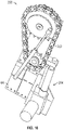
FIG. 18 is a perspective view of a linear actuator assembly for automatically opening and closing a spa cover. -
FIG. 19 is an elevational view of the linear actuator assembly ofFIG. 18 -
FIG. 20 is a perspective view of a friction plate torque limiter of the linear actuator assembly ofFIG. 19 . -
FIG. 21 is an exploded, perspective view of the torque limiter ofFIG. 20 . -
FIG. 22 is an elevational view of a linear actuator assembly. -
FIG. 23 is a perspective view of a ball/spring torque limiter of the linear actuator assembly ofFIG. 22 . -
FIG. 24 is an exploded, perspective view of the torque limiter ofFIG. 23 . - Referring to
FIGS. 1-4 , acover lift system 10 is illustrated. Thecover lift system 10 includes alifter handle 12 having a generally tubular first,upper arm 14 and a generally tubular, secondlower arm 16 telescopically received by theupper arm 14. Theupper arm 14 is generally L-shaped and includes ahollow connector member 18 that extends generally perpendicularly from an upper end of theupper arm 14, which is configured to facilitate the attachment of acrossbar 20 of thecover lift system 10 to theupper arm 14 in the manner discussed hereinafter. Similarly, thelower arm 16 is generally L-shaped and has ahollow connector member 22 that extends generally perpendicularly from a lower end of thelower arm 16, which is configured to facilitate coupling of a lift-assist mechanism of thecover lift system 10 to thelower arm 16, in the manner discussed hereinafter. - With specific reference to
FIGS. 5-7 , the lifter handle 12 includes anadjuster mechanism 24 for selectively adjusting a length of lifter handle 12 and, in particular, a distance, d, between theconnector member 18 of theupper arm 14 and theconnector member 22 of thelower arm 16. In particular, theadjuster mechanism 24 is selectively actuatable to either draw theconnector members connector members adjuster mechanism 24 is a linear actuator such as, for example, a leadscrew. In particular, as illustrated inFIG. 7 , theadjuster mechanism 24 may include aleadscrew 26 mounted in fixed longitudinal position within the hollowupper arm 14 via fixingmember 28. Theleadscrew 26 has adrive head 30 configured for mating coupling with a hex socket (not shown) that enables theleadscrew 26 to be rotated within theupper arm 14 and fixingmember 28. Within the upper end of thelower arm 16 is fixedly mounted anut 32 having a threadedbore 34 for threadedly receiving adistal end 36 of theleadscrew 26. - In operation, a socket (not shown) may be inserted into an open,
upper end 38 of theupper arm 14 and engaged with thedrive head 30 of theleadscrew 26 to rotate theleadscrew 26 while thenut 32 within thelower arm 16 remains stationary. Depending on the direction of rotation of theleadscrew 26, thenut 32 is either drawn up the leadscrew towards thehead 28, thereby drawing thelower arm 16 further into theupper arm 14 and decreasing the distance, d, or advanced towards thedistal end 36 of theleadscrew 26, thereby extending thelower arm 16 from theupper arm 14 and increasing the distance, d. While theadjuster mechanism 24 is shown and described herein as taking the form of a leadscrew, other types of linear actuators known in the art may also be utilized without departing from the broader aspects of the invention. Importantly, theadjuster mechanism 24 allows for the selective adjustment of the distance, d, between theconnector member 18 of theupper arm 14 and theconnector member 22 of thelower arm 16, enabling thecover lift system 10 to be utilized with a range of spa sizes. - Referring now to
FIGS. 6-9 , thehollow connector member 18 of theupper arm 14 contains a firstmechanical coupling member 40 fixedly mounted therein, which is configured to matingly engage a corresponding secondmechanical coupling member 42 fixedly mounted within thecrossbar 20.FIGS. 6 and7 illustrate the first coupling member mounted within thehollow connector member 18 of theupper arm 14. As illustrated inFIGS. 8 and 9 , therespective coupling members hollow connector member 18 of theupper arm 14 and thecrossbar 20, respectively. As best shown inFIGS. 8 and 9 , for example, thecoupling members coupling member 42 within thecrossbar 20, may include a key 44 configured to be received in acorresponding slot 46 of thecoupling member 40 of theupper arm 14 to connect thecrossbar 20 to theupper arm 14 of thelifter handle 12.Bores coupling members slot 46 prevents relative rotation of thecrossbar 20 with respect to thehollow connector member 18 so that a rotational covering or uncovering force can be transmitted from the lifter handle 12 to the crossbar 20 (and ultimately to a cover member), as discussed hereinafter. - Turning now to
FIGS. 10-12 , thehollow connector member 22 of thelower arm 16 contains a thirdmechanical coupling member 52 fixedly mounted therein, which is configured to matingly engage ashaft insert 54 of a lifter mechanism (andshaft 55 thereof), as described in detail hereinafter. As illustrated inFIGS. 10 and 11 , thecoupling member 52 andshaft insert 54 may be substantially cylindrical in shape. Importantly, one of thecoupling member 52 and shaft insert 54 (e.g., theshaft insert 54 inFIG. 10 ) may have a stepped geometry in the form of a key 56 at one end thereof that tapers to a narrow tip. This stepped key 56 is configured to be received in a correspondingly shaped steppedslot 58 formed in an end of the other of thecoupling member 52 and the shaft insert 54 (e.g. thecoupling member 52 inFIG. 11 ).Bores coupling member 52 andshaft insert 54, one or both of which may be threaded. Importantly, the geometry of the interfaces (namely, the stepped key 56 and corresponding keyway or slot 58) allow the lifter handle 12 to be inserted onto thelifter mechanism shaft 54 with up to about a 20 degree rotational misalignment and still be drawn together with a bolt (throughbores 60, 62) that will pull them to proper alignment.FIG. 12 illustrates how a successful mating and interlocking between the couplingmember 52 andshaft insert 54 can be achieved even with a substantial misalignment between the two parts. - This feature not only makes it very easy to assemble these parts during manufacturing, but it allows for servicing in the field without the necessity of removing the sides of the spa. Moreover, when the system is fully assembled, the lifter mechanism (not shown) is loaded with an air spring that causes it to rotate about 18 degrees out of alignment with the lifter handle 12 when the cover is lying flat atop the spa. This coupling design allows the
non-aligned coupling member 52 and shaft insert 54 to be mated together and pulled into alignment simply by tightening a bolt that extends through both parts. - Referring once again to
FIGS. 1-3 , thecover lift system 10 also includes a generally planar mountingbracket 64 having a plurality ofapertures 66 through which fasteners may be inserted to couple thecover lift system 10 to a frame of a spa. For example, in an embodiment, the mountingbracket 64 may be mounted to an upright 68 or corner strut of a frame of a spa. As best shown inFIG. 2 , theshaft insert 54, which is mated with thecoupling 52 within theconnector member 22 of thelower arm 16, extends through anaperture 70 in the mountingbracket 64 and through theframe upright 68. The end of theshaft insert 54 is configured for operative connection to the upper end of a lift assist mechanism (not shown), such as a gas spring, that provides an assisting force for a covering and/or uncovering operation. - As shown in
FIG. 2-4 , thecover lift system 10 further includes apivot mechanism 72 operatively connected to a lower end of the mountingbracket 64 on the inside surface thereof and which extends though theframe upright 68 to receive a lower end of the lift assist mechanism (e.g., a gas spring).FIGS. 13-15 more clearly show the configuration of thepivot mechanism 72. Thepivot mechanism 72 includes aball stud holder 74 and aball stud 76. Theball stud holder 74 is generally cylindrical in shape and has a pair of opposed wrenchingflats 78 on one end thereof. Theball stud holder 74 also includes a threadedcenter bolt hole 80 that is configured to receive a bolt for attaching theball stud holder 74 to the mountingbracket 64 using a bolt, and a threadedaperture 82 on the end with the wrenchingflats 78 for threadedly receiving a correspondingly threaded portion of theball stud 76. As illustrated inFIG. 14 , the threadedaperture 82 for mounting theball stud 76 is offset from a central axis of theball stud holder 74. - As indicated above, the
pivot mechanism 72 holds the lower end of the lift assist mechanism (e.g., the gas spring). The offset of theball stud 76 from the central axis of theball stud holder 74 allows theball stud 76 to be rotated out of position around the center bolt (not shown) that is received through thecenter bolt hole 80. The lift assist mechanism can then be attached by hand to theball stud 76 with little effort. A wrench can then be used to engage the wrenchingflats 78 to rotate the ball stud into position, exerting a compression load on the gas spring of the lift assist mechanism. This is accomplished by aligning a smaller threadedhole 84 on the other end of the ball stud holder 74 (that is likewise offset from the central axis) with ahole 86 in thebracket 64 and inserting a bolt to hold it in place. In this manner, the gas spring of the lift assist mechanism can be installed an compressed with very little effort in tightly enclosed space within the spa cabinet. -
FIGS. 16 and17 illustrate thecover lift system 10 installed within aspa 100. In particular,spa 100 incudes a pair ofcover lift systems 10 for covering and uncovering first andsecond cover members FIGS. 16 and17 , eachcover lift system 10 is attached to the outside surface of the frame uprights 68 of the frame of thespa 100. The crossbars extend though thecover member cover members cover members cover members - In particular, in use, a gas spring mounted on the interior side of the
bracket 64 provides a lift-assist force for both an uncovering and covering operation. In particular, when the cover is in a closed position, the lift-assist mechanism exerts a generally upward force on the cover member. To uncover the spa, a user grasps the lifter handle 12 and, in particular, theupper arm 14 thereof, and rotates the lifter handle 12 about a horizontal axis that extends through theconnector member 22 of thelower arm 16. This rotational force is transmitted through the lifter handle 12 and thecrossbar 20 that extends through the cover member, causing the cover member to slide from atop the spa to an uncovered position. - Importantly, the
cover lift system 10 is configured such that thebrackets 64 and other components thereof are hidden under the spa cabinet side panels (which are removed inFIGS. 16 and17 ) during use. Thecover lift system 10, however, can be easily installed and serviced in the field simply by removing the side panels. - Referring now to
FIGS. 18 and19 , alinear actuator assembly 200 that can be used to automatically open and close thespa cover members linear actuator assembly 200 mounts internally to the spa frame and connects to thecover lifter system 10 described above. The electrically driven linear actuator drives achain 202 that rotates thelifter handle 12. This automated lift assembly can be chain driven from alinear actuator 204, as shown, or can be linkage driven with or without the chain with simple linkages such as a crank rocker configuration to rotate the lifter handle 12 and open the spa cover. With reference toFIGS. 20 and 21 , thelinear actuator assembly 200 may include a friction platetype torque limiter 210 used for breakaway safety. - With reference to
FIGS. 22-24 , in an embodiment, anautomated lifter mechanism 300 may alternatively usemechanical linkages linear actuator 304 with thedisk 306 for rotatably driving the disk (and thus lifter handle 12). As shown inFIGS. 23 and 24 , this design may incorporate a ball/spring torque limiter 310 for use as a breakaway safety mechanism. - In either implementation, the torque limiting breakaway mechanism functions to release the drive mechanism from the cover when resistance to opening or closing is encountered by people or objects. In addition, the toque limiting breakaway mechanism is configured to decouples the drive mechanism from the cover when a person lifts up on the cover with nominative and sufficient force to break it free in an emergency or out of power situation where the spa cover needs to be opened. In an embodiment, the torque limiting breakaway mechanism will release the drive mechanism from the cover and will be fully restored to normal operating conditions when the cover is recycled through a normal opening and closing cycle.
- Although this invention has been shown and described with respect to the detailed embodiments thereof, it will be understood by those of skill in the art that various changes may be made and equivalents may be substituted for elements thereof without departing from the scope of the invention, all within the appended claims.
Claims (11)
- A cover lift system (10) for a spa (100), comprising:a lifter handle (12) having an upper arm (14) and a lower arm (16) telescopically connected to the upper arm (14), the upper arm (14) being configured for operative connection to a cover (102) of a spa (100), and the lower arm (16) being configured for pivotal connection to a base of the spa (100); andan adjuster mechanism (24) associated with the lifter handle (12) for selectively adjusting a length of the lifter handle (12) to allow for use of the lifter handle (12) with spas of varying sizes;characterized byfurther comprising a breakaway mechanism (210) configured to limit an amount of torque seen by the lifter handle (12) during a covering or uncovering operation.
- The cover lift system (10) of claim 1, wherein the adjuster mechanism (24) is a linear actuator housed within the upper arm (14) and the lower arm (16).
- The cover lift system (10) of claim 2, wherein:the linear actuator includes a leadscrew (26) in fixed longitudinal position within the upper arm (14) and a nut (32) in fixed position within the lower arm (16);wherein the leadscrew (26) is threadedly received by the nut (32).
- The cover lift system (10) of claim 3, wherein:the leadscrew (26) includes a drive head (30) accessible through an upper end of the upper arm (14);wherein the leadscrew (26) is rotatable via the drive head (30) to adjust the distance between the first point and the second point.
- The cover lift system (10) of claim 1, further comprising:
a first coupling member (40) associated with the upper arm (14), the first coupling member (40) being configured to matingly engage a second coupling member (42) associated with a crossbar (20) that extends through the cover (102) of the spa (100). - The cover lift system (10) of claim 5, further comprising:
a third coupling member (52) associated with the lower arm (16), the third coupling member (52) being configured to matingly engage a shaft insert (54) of a lift-assist mechanism. - The cover lift system (10) of claim 6, wherein:
the third coupling member (52) and the shaft insert (54) have geometries that allow for a degree of rotational misalignment between the third coupling member (52) and the shaft insert (54) when mating the third coupling member (52) to the shaft insert (54). - The cover lift system (10) of claim 7, wherein:
one of the third coupling member (52) and the shaft insert (54) has a stepped end that is receivable in a corresponding stepped slot in the other of the third coupling member (52) and the shaft insert (54). - The cover lift system (10) of claim 8, wherein:
the degree of rotational misalignment is about 20 degrees. - The cover lift system (10) of claim 1, further comprising:
a mounting bracket (64) operatively connected to the lower arm (16), the mounting bracket (64) being configured to attach the cover lift system (10) to an external side of a frame of the spa (100). - The cover lift system (10) of claim 10, further comprising:a pivot mechanism (72) mounted to the mounting bracket (64) below the point of connection of the lower arm (16) to the mounting bracket (64);the pivot mechanism (72) being configured to pivotally receive a lower end of a lift-assist mechanism.
Applications Claiming Priority (2)
| Application Number | Priority Date | Filing Date | Title |
|---|---|---|---|
| US201762458164P | 2017-02-13 | 2017-02-13 | |
| PCT/US2018/017921 WO2018148706A1 (en) | 2017-02-13 | 2018-02-13 | System, method and apparatus for opening a spa hard cover |
Publications (3)
| Publication Number | Publication Date |
|---|---|
| EP3580410A1 EP3580410A1 (en) | 2019-12-18 |
| EP3580410A4 EP3580410A4 (en) | 2021-04-14 |
| EP3580410B1 true EP3580410B1 (en) | 2023-01-04 |
Family
ID=63106219
Family Applications (1)
| Application Number | Title | Priority Date | Filing Date |
|---|---|---|---|
| EP18751582.0A Active EP3580410B1 (en) | 2017-02-13 | 2018-02-13 | Cover lift system for a spa |
Country Status (5)
| Country | Link |
|---|---|
| US (2) | US10519680B2 (en) |
| EP (1) | EP3580410B1 (en) |
| CN (1) | CN110234823B (en) |
| CA (1) | CA3049986C (en) |
| WO (1) | WO2018148706A1 (en) |
Families Citing this family (7)
| Publication number | Priority date | Publication date | Assignee | Title |
|---|---|---|---|---|
| US10370864B2 (en) * | 2016-03-31 | 2019-08-06 | Carl Gavin | Spa cover lifter system and method |
| CA3049986C (en) * | 2017-02-13 | 2022-07-12 | Strong Industries, Inc. | System, method and apparatus for opening a spa hard cover |
| DE102018130405A1 (en) * | 2018-11-29 | 2020-06-04 | Basi Gmbh | Bar handle for building doors |
| CA3126083A1 (en) * | 2019-01-28 | 2020-08-06 | Strong Industries, Inc. | Lift system for a spa cover |
| US11078679B2 (en) * | 2019-08-02 | 2021-08-03 | Hot Tub Products, Llc | Universal system to mechanize a cover lifter on a spa tub |
| CN110815876B (en) * | 2019-10-31 | 2021-10-15 | 深圳市佳鑫一帆科技有限公司 | Plastic housing processingequipment with adsorb smell multilayer purification structure |
| AU2021307471B2 (en) * | 2020-07-16 | 2022-12-15 | Vortex Leisure Pty Ltd | A spa pool cover lifter, and a spa pool including a spa pool cover lifter |
Family Cites Families (14)
| Publication number | Priority date | Publication date | Assignee | Title |
|---|---|---|---|---|
| US5566403A (en) | 1994-09-06 | 1996-10-22 | Black; Marc S. | Spa cover lift apparatus |
| FR2741898B1 (en) * | 1995-11-30 | 1998-01-23 | Toutenkamion | MOBILE COVERING DEVICE, PARTICULARLY FOR POOLS |
| US6634036B2 (en) | 2002-02-08 | 2003-10-21 | E. Jess Tudor | Foldable spa cover and lift unit |
| US7412931B2 (en) * | 2002-06-07 | 2008-08-19 | Krueger International, Inc. | Quick crank adjustable height table |
| US6795984B1 (en) * | 2003-01-08 | 2004-09-28 | James P. Brady | Spa cover lifting device |
| US20060053543A1 (en) * | 2003-01-27 | 2006-03-16 | Pedro Vargas | Water recreational apparatus with powered cover |
| US7600272B2 (en) * | 2005-01-21 | 2009-10-13 | Merlin Technologies, Inc. | Spa cover lifter and method |
| US7752685B2 (en) * | 2005-11-15 | 2010-07-13 | Tudor E Jess | Foldable spa cover device |
| US20090211011A1 (en) | 2008-02-21 | 2009-08-27 | Victor Lee Walker | Panel Systems for Spas |
| US8516625B2 (en) * | 2010-12-02 | 2013-08-27 | Hottubproducts.Com, Llc | Spa cover |
| CA2898993C (en) * | 2013-01-22 | 2017-12-19 | Strong Industries | Cover assembly for a spa |
| US20150345163A1 (en) * | 2014-06-02 | 2015-12-03 | John Cunerty | Adjustable Support Member for a Spa Cover Lifting Device |
| US10487523B2 (en) * | 2014-11-03 | 2019-11-26 | Strong Industries, Inc. | Lift assembly and spa including the same |
| CA3049986C (en) * | 2017-02-13 | 2022-07-12 | Strong Industries, Inc. | System, method and apparatus for opening a spa hard cover |
-
2018
- 2018-02-13 CA CA3049986A patent/CA3049986C/en active Active
- 2018-02-13 WO PCT/US2018/017921 patent/WO2018148706A1/en not_active Ceased
- 2018-02-13 CN CN201880009195.2A patent/CN110234823B/en active Active
- 2018-02-13 US US15/895,087 patent/US10519680B2/en active Active
- 2018-02-13 EP EP18751582.0A patent/EP3580410B1/en active Active
-
2019
- 2019-11-26 US US16/695,751 patent/US11384555B2/en active Active
Also Published As
| Publication number | Publication date |
|---|---|
| US11384555B2 (en) | 2022-07-12 |
| CA3049986A1 (en) | 2018-08-16 |
| US20180230705A1 (en) | 2018-08-16 |
| WO2018148706A1 (en) | 2018-08-16 |
| CN110234823A (en) | 2019-09-13 |
| US20200095790A1 (en) | 2020-03-26 |
| CA3049986C (en) | 2022-07-12 |
| EP3580410A1 (en) | 2019-12-18 |
| US10519680B2 (en) | 2019-12-31 |
| CN110234823B (en) | 2021-12-21 |
| EP3580410A4 (en) | 2021-04-14 |
Similar Documents
| Publication | Publication Date | Title |
|---|---|---|
| US11384555B2 (en) | System, method and apparatus for opening a spa hard cover | |
| US10526807B2 (en) | Lift assembly and spa including the same | |
| US12345066B2 (en) | Lift system for a spa cover | |
| US7971287B2 (en) | Method and apparatus for automatically lifting a cover | |
| US7461415B2 (en) | Method and apparatus for automatically lifting a cover | |
| CN201460560U (en) | Connecting bar with automatic movement mechanism | |
| EP3215694A1 (en) | Lift assembly and spa including the same | |
| US20240159070A1 (en) | Spa cover lift system |
Legal Events
| Date | Code | Title | Description |
|---|---|---|---|
| STAA | Information on the status of an ep patent application or granted ep patent |
Free format text: STATUS: THE INTERNATIONAL PUBLICATION HAS BEEN MADE |
|
| PUAI | Public reference made under article 153(3) epc to a published international application that has entered the european phase |
Free format text: ORIGINAL CODE: 0009012 |
|
| STAA | Information on the status of an ep patent application or granted ep patent |
Free format text: STATUS: REQUEST FOR EXAMINATION WAS MADE |
|
| 17P | Request for examination filed |
Effective date: 20190902 |
|
| AK | Designated contracting states |
Kind code of ref document: A1 Designated state(s): AL AT BE BG CH CY CZ DE DK EE ES FI FR GB GR HR HU IE IS IT LI LT LU LV MC MK MT NL NO PL PT RO RS SE SI SK SM TR |
|
| AX | Request for extension of the european patent |
Extension state: BA ME |
|
| DAV | Request for validation of the european patent (deleted) | ||
| DAX | Request for extension of the european patent (deleted) | ||
| RIC1 | Information provided on ipc code assigned before grant |
Ipc: E04H 4/08 20060101AFI20201119BHEP Ipc: F16B 7/18 20060101ALI20201119BHEP |
|
| RIC1 | Information provided on ipc code assigned before grant |
Ipc: E04H 4/08 20060101AFI20210222BHEP Ipc: F16B 7/18 20060101ALI20210222BHEP |
|
| RIC1 | Information provided on ipc code assigned before grant |
Ipc: F16B 7/18 20060101ALI20210304BHEP Ipc: E04H 4/08 20060101AFI20210304BHEP |
|
| A4 | Supplementary search report drawn up and despatched |
Effective date: 20210315 |
|
| RIC1 | Information provided on ipc code assigned before grant |
Ipc: E04H 4/08 20060101AFI20210309BHEP Ipc: F16B 7/18 20060101ALI20210309BHEP |
|
| GRAP | Despatch of communication of intention to grant a patent |
Free format text: ORIGINAL CODE: EPIDOSNIGR1 |
|
| STAA | Information on the status of an ep patent application or granted ep patent |
Free format text: STATUS: GRANT OF PATENT IS INTENDED |
|
| INTG | Intention to grant announced |
Effective date: 20220712 |
|
| GRAS | Grant fee paid |
Free format text: ORIGINAL CODE: EPIDOSNIGR3 |
|
| GRAA | (expected) grant |
Free format text: ORIGINAL CODE: 0009210 |
|
| STAA | Information on the status of an ep patent application or granted ep patent |
Free format text: STATUS: THE PATENT HAS BEEN GRANTED |
|
| AK | Designated contracting states |
Kind code of ref document: B1 Designated state(s): AL AT BE BG CH CY CZ DE DK EE ES FI FR GB GR HR HU IE IS IT LI LT LU LV MC MK MT NL NO PL PT RO RS SE SI SK SM TR |
|
| REG | Reference to a national code |
Ref country code: GB Ref legal event code: FG4D |
|
| REG | Reference to a national code |
Ref country code: CH Ref legal event code: EP |
|
| REG | Reference to a national code |
Ref country code: AT Ref legal event code: REF Ref document number: 1542021 Country of ref document: AT Kind code of ref document: T Effective date: 20230115 |
|
| REG | Reference to a national code |
Ref country code: DE Ref legal event code: R096 Ref document number: 602018045020 Country of ref document: DE |
|
| REG | Reference to a national code |
Ref country code: IE Ref legal event code: FG4D |
|
| REG | Reference to a national code |
Ref country code: LT Ref legal event code: MG9D |
|
| REG | Reference to a national code |
Ref country code: AT Ref legal event code: MK05 Ref document number: 1542021 Country of ref document: AT Kind code of ref document: T Effective date: 20230104 |
|
| PG25 | Lapsed in a contracting state [announced via postgrant information from national office to epo] |
Ref country code: NL Free format text: LAPSE BECAUSE OF FAILURE TO SUBMIT A TRANSLATION OF THE DESCRIPTION OR TO PAY THE FEE WITHIN THE PRESCRIBED TIME-LIMIT Effective date: 20230104 |
|
| PG25 | Lapsed in a contracting state [announced via postgrant information from national office to epo] |
Ref country code: RS Free format text: LAPSE BECAUSE OF FAILURE TO SUBMIT A TRANSLATION OF THE DESCRIPTION OR TO PAY THE FEE WITHIN THE PRESCRIBED TIME-LIMIT Effective date: 20230104 Ref country code: PT Free format text: LAPSE BECAUSE OF FAILURE TO SUBMIT A TRANSLATION OF THE DESCRIPTION OR TO PAY THE FEE WITHIN THE PRESCRIBED TIME-LIMIT Effective date: 20230504 Ref country code: NO Free format text: LAPSE BECAUSE OF FAILURE TO SUBMIT A TRANSLATION OF THE DESCRIPTION OR TO PAY THE FEE WITHIN THE PRESCRIBED TIME-LIMIT Effective date: 20230404 Ref country code: LV Free format text: LAPSE BECAUSE OF FAILURE TO SUBMIT A TRANSLATION OF THE DESCRIPTION OR TO PAY THE FEE WITHIN THE PRESCRIBED TIME-LIMIT Effective date: 20230104 Ref country code: LT Free format text: LAPSE BECAUSE OF FAILURE TO SUBMIT A TRANSLATION OF THE DESCRIPTION OR TO PAY THE FEE WITHIN THE PRESCRIBED TIME-LIMIT Effective date: 20230104 Ref country code: HR Free format text: LAPSE BECAUSE OF FAILURE TO SUBMIT A TRANSLATION OF THE DESCRIPTION OR TO PAY THE FEE WITHIN THE PRESCRIBED TIME-LIMIT Effective date: 20230104 Ref country code: ES Free format text: LAPSE BECAUSE OF FAILURE TO SUBMIT A TRANSLATION OF THE DESCRIPTION OR TO PAY THE FEE WITHIN THE PRESCRIBED TIME-LIMIT Effective date: 20230104 Ref country code: AT Free format text: LAPSE BECAUSE OF FAILURE TO SUBMIT A TRANSLATION OF THE DESCRIPTION OR TO PAY THE FEE WITHIN THE PRESCRIBED TIME-LIMIT Effective date: 20230104 |
|
| PG25 | Lapsed in a contracting state [announced via postgrant information from national office to epo] |
Ref country code: SE Free format text: LAPSE BECAUSE OF FAILURE TO SUBMIT A TRANSLATION OF THE DESCRIPTION OR TO PAY THE FEE WITHIN THE PRESCRIBED TIME-LIMIT Effective date: 20230104 Ref country code: PL Free format text: LAPSE BECAUSE OF FAILURE TO SUBMIT A TRANSLATION OF THE DESCRIPTION OR TO PAY THE FEE WITHIN THE PRESCRIBED TIME-LIMIT Effective date: 20230104 Ref country code: IS Free format text: LAPSE BECAUSE OF FAILURE TO SUBMIT A TRANSLATION OF THE DESCRIPTION OR TO PAY THE FEE WITHIN THE PRESCRIBED TIME-LIMIT Effective date: 20230504 Ref country code: GR Free format text: LAPSE BECAUSE OF FAILURE TO SUBMIT A TRANSLATION OF THE DESCRIPTION OR TO PAY THE FEE WITHIN THE PRESCRIBED TIME-LIMIT Effective date: 20230405 Ref country code: FI Free format text: LAPSE BECAUSE OF FAILURE TO SUBMIT A TRANSLATION OF THE DESCRIPTION OR TO PAY THE FEE WITHIN THE PRESCRIBED TIME-LIMIT Effective date: 20230104 |
|
| REG | Reference to a national code |
Ref country code: DE Ref legal event code: R119 Ref document number: 602018045020 Country of ref document: DE |
|
| REG | Reference to a national code |
Ref country code: CH Ref legal event code: PL |
|
| REG | Reference to a national code |
Ref country code: BE Ref legal event code: MM Effective date: 20230228 |
|
| PG25 | Lapsed in a contracting state [announced via postgrant information from national office to epo] |
Ref country code: SM Free format text: LAPSE BECAUSE OF FAILURE TO SUBMIT A TRANSLATION OF THE DESCRIPTION OR TO PAY THE FEE WITHIN THE PRESCRIBED TIME-LIMIT Effective date: 20230104 Ref country code: RO Free format text: LAPSE BECAUSE OF FAILURE TO SUBMIT A TRANSLATION OF THE DESCRIPTION OR TO PAY THE FEE WITHIN THE PRESCRIBED TIME-LIMIT Effective date: 20230104 Ref country code: MC Free format text: LAPSE BECAUSE OF FAILURE TO SUBMIT A TRANSLATION OF THE DESCRIPTION OR TO PAY THE FEE WITHIN THE PRESCRIBED TIME-LIMIT Effective date: 20230104 Ref country code: LU Free format text: LAPSE BECAUSE OF NON-PAYMENT OF DUE FEES Effective date: 20230213 Ref country code: LI Free format text: LAPSE BECAUSE OF NON-PAYMENT OF DUE FEES Effective date: 20230228 Ref country code: EE Free format text: LAPSE BECAUSE OF FAILURE TO SUBMIT A TRANSLATION OF THE DESCRIPTION OR TO PAY THE FEE WITHIN THE PRESCRIBED TIME-LIMIT Effective date: 20230104 Ref country code: DK Free format text: LAPSE BECAUSE OF FAILURE TO SUBMIT A TRANSLATION OF THE DESCRIPTION OR TO PAY THE FEE WITHIN THE PRESCRIBED TIME-LIMIT Effective date: 20230104 Ref country code: CZ Free format text: LAPSE BECAUSE OF FAILURE TO SUBMIT A TRANSLATION OF THE DESCRIPTION OR TO PAY THE FEE WITHIN THE PRESCRIBED TIME-LIMIT Effective date: 20230104 Ref country code: CH Free format text: LAPSE BECAUSE OF NON-PAYMENT OF DUE FEES Effective date: 20230228 |
|
| PLBE | No opposition filed within time limit |
Free format text: ORIGINAL CODE: 0009261 |
|
| STAA | Information on the status of an ep patent application or granted ep patent |
Free format text: STATUS: NO OPPOSITION FILED WITHIN TIME LIMIT |
|
| PG25 | Lapsed in a contracting state [announced via postgrant information from national office to epo] |
Ref country code: SK Free format text: LAPSE BECAUSE OF FAILURE TO SUBMIT A TRANSLATION OF THE DESCRIPTION OR TO PAY THE FEE WITHIN THE PRESCRIBED TIME-LIMIT Effective date: 20230104 |
|
| 26N | No opposition filed |
Effective date: 20231005 |
|
| REG | Reference to a national code |
Ref country code: IE Ref legal event code: MM4A |
|
| GBPC | Gb: european patent ceased through non-payment of renewal fee |
Effective date: 20230404 |
|
| PG25 | Lapsed in a contracting state [announced via postgrant information from national office to epo] |
Ref country code: GB Free format text: LAPSE BECAUSE OF NON-PAYMENT OF DUE FEES Effective date: 20230404 |
|
| PG25 | Lapsed in a contracting state [announced via postgrant information from national office to epo] |
Ref country code: SI Free format text: LAPSE BECAUSE OF FAILURE TO SUBMIT A TRANSLATION OF THE DESCRIPTION OR TO PAY THE FEE WITHIN THE PRESCRIBED TIME-LIMIT Effective date: 20230104 Ref country code: IE Free format text: LAPSE BECAUSE OF NON-PAYMENT OF DUE FEES Effective date: 20230213 Ref country code: GB Free format text: LAPSE BECAUSE OF NON-PAYMENT OF DUE FEES Effective date: 20230404 Ref country code: FR Free format text: LAPSE BECAUSE OF NON-PAYMENT OF DUE FEES Effective date: 20230304 Ref country code: DE Free format text: LAPSE BECAUSE OF NON-PAYMENT OF DUE FEES Effective date: 20230901 |
|
| PG25 | Lapsed in a contracting state [announced via postgrant information from national office to epo] |
Ref country code: BE Free format text: LAPSE BECAUSE OF NON-PAYMENT OF DUE FEES Effective date: 20230228 |
|
| PG25 | Lapsed in a contracting state [announced via postgrant information from national office to epo] |
Ref country code: IT Free format text: LAPSE BECAUSE OF FAILURE TO SUBMIT A TRANSLATION OF THE DESCRIPTION OR TO PAY THE FEE WITHIN THE PRESCRIBED TIME-LIMIT Effective date: 20230104 |
|
| PG25 | Lapsed in a contracting state [announced via postgrant information from national office to epo] |
Ref country code: BG Free format text: LAPSE BECAUSE OF FAILURE TO SUBMIT A TRANSLATION OF THE DESCRIPTION OR TO PAY THE FEE WITHIN THE PRESCRIBED TIME-LIMIT Effective date: 20230104 |
|
| PG25 | Lapsed in a contracting state [announced via postgrant information from national office to epo] |
Ref country code: BG Free format text: LAPSE BECAUSE OF FAILURE TO SUBMIT A TRANSLATION OF THE DESCRIPTION OR TO PAY THE FEE WITHIN THE PRESCRIBED TIME-LIMIT Effective date: 20230104 |
|
| PG25 | Lapsed in a contracting state [announced via postgrant information from national office to epo] |
Ref country code: CY Free format text: LAPSE BECAUSE OF FAILURE TO SUBMIT A TRANSLATION OF THE DESCRIPTION OR TO PAY THE FEE WITHIN THE PRESCRIBED TIME-LIMIT; INVALID AB INITIO Effective date: 20180213 |
|
| PG25 | Lapsed in a contracting state [announced via postgrant information from national office to epo] |
Ref country code: HU Free format text: LAPSE BECAUSE OF FAILURE TO SUBMIT A TRANSLATION OF THE DESCRIPTION OR TO PAY THE FEE WITHIN THE PRESCRIBED TIME-LIMIT; INVALID AB INITIO Effective date: 20180213 |
|
| PG25 | Lapsed in a contracting state [announced via postgrant information from national office to epo] |
Ref country code: TR Free format text: LAPSE BECAUSE OF FAILURE TO SUBMIT A TRANSLATION OF THE DESCRIPTION OR TO PAY THE FEE WITHIN THE PRESCRIBED TIME-LIMIT Effective date: 20230104 |